


Abstract
Thermal management limits the performance of densely integrated electronics. Heat-sink surfaces are conventionally passive elements dedicated to heat rejection. Here we show that one conformal single-walled carbon nanotube (SWCNT) coating renders such a surface dual-functional. The coating comprises p- and n-type SWCNT films whose porous, mesh-like network enlarges the effective surface area and raises the emissivity. It converts part of the rejected heat into electricity through the Seebeck effect. We applied the coating to an alumite-insulated aluminum screw, a compact model of an extended heat-sink surface. Under forced convection at 3.0 m/s, the coating lowered the hot-side temperature of the screw by up to 22 K, from 341.8 K to 319.4 K. Cooling was optimal at 75% axial coverage. Repeated runs and an independently fabricated device confirmed this optimum. The apparent heat-transfer coefficient, defined on the total heater input and on the metallic reference area, rose 1.6-fold, from 172 to 278 W/(m2·K). At full coverage, the same layer generated 0.72 mV and 1.0 nW per p–n pair. The cooling optimum and the power optimum occur at different coverages, which yields a practical design freedom. These results recast the surfaces of cooling components as multifunctional, thermally active layers.
1. Introduction
Heat sinks are indispensable in modern electronics. They dissipate excess thermal energy, prevent thermal runaway, and ensure reliable operation [1,2]. Rising power densities have made thermal management a critical bottleneck for device performance [3,4]. Extended surfaces such as fins, pins, and threads enlarge the air-contact area of a heat sink [5]. Chip-level schemes such as thermoelectric microcoolers and two-phase microgap coolers instead target the hot spot directly [6]. Improving these ubiquitous cooling surfaces without adding bulk or complexity remains a central engineering goal. The thin anodic aluminum oxide (alumite) layer used here is one example of a functional surface layer: it insulates the surface electrically and preserves the high thermal conductance of the aluminum core. High-emissivity coatings are an established route to enhanced radiative dissipation [7].
Carbon nanotube (CNT) coatings enhance heat dissipation from metallic surfaces. Layer-by-layer (LbL) coatings of multi-walled carbon nanotubes (MWCNTs) and polyethyleneimine (PEI) on aluminum heat sinks raise the heat-transfer coefficient by ≈19% and lower the thermal resistance by 16% [8]. Brush-coated CNT films lower the case temperature of an LED heat sink by ≈16% relative to an uncoated aluminum plate [9]. CNT coatings on fin-and-tube heat exchangers improve convective heat transfer under dry conditions [10]. Recent reviews of heat-sink coatings [11] and of carbon-based heat-sink materials [12] identify the parameters that govern such coatings. These are the surface emissivity, the surface roughness, and the thermal resistance of the coating. Both reviews rank carbon nanomaterials among the most effective coating materials. Single-walled carbon nanotubes (SWCNTs) deposited from dispersion interweave into a mesh-like, highly porous network. This network combines a large specific surface area with a high emissivity. Both properties favor convective and radiative heat exchange with the surrounding air. SWCNTs combine high intrinsic thermal conductivity with large thermoelectric power factors and solution processability [13,14]. Printed SWCNT films conform to non-planar surfaces [15], including the curved threaded geometries of real heat-transfer hardware.
Several bottlenecks nevertheless constrain the performance and deployment of CNT-based thermal and thermoelectric devices. The most fundamental is interfacial thermal resistance. An individual CNT has an extremely high axial thermal conductivity. In a macroscopic assembly, heat must repeatedly cross inter-tube, inter-bundle, and CNT–substrate junctions. Weak van der Waals coupling and phonon-spectrum mismatch produce large contact resistances at these junctions. The effective thermal conductivity of the network therefore falls orders of magnitude below that of the constituent tubes [16]. Batch-to-batch variability of dispersion- and coating-based fabrication compounds this bottleneck. In thermoelectric devices, contact resistances at the electrical interconnects add a further loss. These factors limit both the attainable heat-dissipation performance and the harvestable output power. Rational design of CNT-based dual-function devices therefore requires deliberate management of the same interfacial resistances, which the present work also turns to advantage. Recent surveys of CNT-based thermoelectrics identify two additional bottlenecks [17]. The first is the trade-off between the Seebeck coefficient and the electrical conductivity of doped CNT networks, which caps the attainable power factor. The second is the electrical contact resistance at metal/CNT interconnects, which frequently exceeds the intrinsic resistance of the thermoelectric legs. The second bottleneck has motivated seamless p–n patterning [18] and jointless junction architectures [19] that eliminate discrete metal joints. The device studied here inherits both constraints. Section 3.3 and Section 3.4 quantify their impact on the measured output.
SWCNT layers offer a further, largely unexploited opportunity. The same coating converts part of the dissipated heat into electricity through the Seebeck effect [20,21,22]. Heat dissipation and thermoelectric generation are usually treated as competing functions, because aggressive cooling flattens the temperature gradient that drives the Seebeck voltage [23,24]. SWCNT networks reconcile the two functions. Individual SWCNTs are thermally conductive [25], yet inter-tube and inter-bundle contact resistances strongly suppress the effective thermal conductivity of SWCNT films [26,27,28]. A useful temperature gradient, and hence a thermoelectric voltage, therefore persists across the coating even on an actively dissipating surface [29,30,31].
Previous studies have pursued cooling enhancement and thermoelectric harvesting as separate goals. CNT coatings served as passive thermal additives [8,9,10]. Thermoelectric harvesting relied on discrete modules bolted onto dedicated heat-transfer components [32,33]. Thermoelectric harvesters for Internet of Things (IoT) nodes follow the same module-based architecture, in which the generator and its heat sink remain separate parts [34]. This separation adds bulk, weight, interfacial thermal resistance, and assembly complexity. It also leaves the large surface area of the cooling element thermoelectrically inactive. One design does combine the two functions in a single component: mesh-structured SWCNT thermoelectric generators dissipate heat more effectively through their open geometry [35]. That work improves the cooling of the generator itself. The present work instead coats an existing heat-sink element, so that the cooling surface becomes the thermoelectric element. A coating that performs both functions on one and the same surface has not been demonstrated.
Here we enhance the heat dissipation of a metallic heat-sink element with a conformal SWCNT coating. The same coating provides a built-in thermoelectric energy-harvesting function. An aluminum-alloy screw serves as a practical model of a finned heat-sink element. Its helical threads provide a large air-contact area in a compact three-dimensional form factor [5]. They represent the extended surfaces found in industrial heat-transfer hardware. A bare metallic screw body would short-circuit the deposited p- and n-type SWCNT layers. We therefore used screws fully covered by an insulating alumite layer, which preserves the high thermal conductance of the aluminum core. The alumite-covered threads were coated conformally with p- and n-type SWCNT films and tested under forced convection at 3.0 m/s. The coating raises the heat-transfer coefficient, lowers the hot-side temperature, and delivers a measurable thermoelectric output from the same surface. This work thereby reinterprets the ubiquitous surfaces of cooling components as multifunctional, thermally active layers, with electronic cooling, distributed IoT sensors, and wearable devices [36,37,38] as the target applications.
2. Experimental Procedure
2.1. Preparation of SWCNT Dispersions
The p-type dispersion was prepared from 0.08 g of SWCNTs (ZEONANO SG101, Zeon Corp., Tokyo, Japan) and 0.2 g of sodium dodecyl sulfate (SDS; Tokyo Chemical Industry Co., Tokyo, Japan) in 40 mL of deionized water. SDS served as the anionic surfactant. The n-type dispersion was prepared from 0.08 g of SWCNTs and 0.4 g of dimethyldioctadecylammonium chloride (DODMAC; Fujifilm Wako Pure Chemical Corp., Tokyo, Japan) in 40 mL of acetone (Fujifilm Wako Pure Chemical). DODMAC served as the cationic surfactant. A second n-type dispersion was prepared from 0.08 g of SWCNTs and 0.4 g of DODMAC in 40 mL of ethanol (purity > 99.5%; Fujifilm Wako Pure Chemical). This dispersion was used for an independently fabricated replicate device (Section 2.4). All three mixtures were processed with a probe-type ultrasonic homogenizer (Sonifier 250, Branson, Brookfield, CT, USA) equipped with a 12.7 mm diameter horn tip. The homogenizer operated at 20 kHz with a maximum ultrasonic amplitude of 115 μm. Each mixture was sonicated at 70% amplitude, corresponding to a nominal power of 200 W, for 30 min. The sample containers were immersed in an ice bath during ultrasonication to prevent overheating.
2.2. Fabrication and Characterization of SWCNT Films
Free-standing films were prepared by vacuum filtration to evaluate the intrinsic properties of the two SWCNT materials. Both dispersions were filtered through a polytetrafluoroethylene (PTFE) membrane filter (90 mm diameter, 10 μm pore size; ADVANTEC, Tokyo, Japan). The p-type films were dried at 333 K for 60 min. The n-type films were dried in a vacuum desiccator (<0.08 MPa) for 120 min. They were then annealed in a 95% Ar–5% H2 atmosphere at 473 K for 1 h to enhance their n-type character. The in-plane electrical conductivity (σ) and Seebeck coefficient (S) were measured from 303 K to 423 K using the ZEM-3 system (Advance Riko, Yokohama, Japan) in a helium atmosphere, with an accuracy of ±5%. Both quantities are in-plane values, measured along the direction in which the Seebeck voltage is extracted from the coated thread. The power factor was calculated as PF = S2σ.
2.3. Fabrication of SWCNT-Coated Screws
Commercial M5 (ISO 7380) aluminum-alloy screws (20 mm in length, 5052 alloy, Saima Corp., Fujisawa, Japan) served as the base structures. Each screw carried a 5–10-μm-thick alumite coating. The dimensional drawing of the screw is given in the Supplementary Materials (Figure S1). The insulation integrity of every screw was verified with a digital multimeter prior to coating. The screws were cleaned ultrasonically in acetone (100 kHz for 10 min) and then dip-coated three times with the dispersions. The SWCNT coverage was varied at four levels, defined as the coated fraction of the threaded surface measured from the screw tip toward the head (Figure 1): 100% (fully coated), 75%, 50%, and 25%. Pristine screws (0% coverage) served as the control group. The n-type coated screws underwent the same vacuum drying and thermal annealing as the free-standing films (Section 2.2).
Figure 1.
Structural configuration and performance-measurement setup of the SWCNT-coated screw devices (schematic cross-section). The p-type and n-type SWCNT-coated screws are mounted head-down on a heated aluminum plate. The head serves as the hot-side contact and the air-cooled tip as the cold side. The two screws are connected electrically in series at their tips. A Peltier module heats the device from below while a 3.0 m/s airflow is applied by forced convection. The labels indicate the positions of the thermocouple sensing wires (p-tip and n-head) and the CNT-interface voltage-sensing wires. Component dimensions and instrument models are given in Section 2.4.
The film thickness on the M5 screw surface is an effective, mass-equivalent value. It follows from the deposited SWCNT mass, the geometric surface area of the threaded shank (353.4 mm2), and the apparent densities of the porous films, 0.34 g/cm3 for the p-type and 0.26 g/cm3 for the n-type film. These densities were determined from the mass and the geometric volume of free-standing films prepared from the same two dispersions, with the film thickness measured using a digital micrometer [22]. At 100% coverage, the effective thickness is ≈31 μm for the p-type layer and ≈95 μm for the n-type layer. Table S2 lists the deposited mass and the effective thickness for every coverage. They range from 20 to 73 μm for the p-type layer and from 89 to 148 μm for the n-type layer, because the deposited mass does not scale with the coated length.
The two thicknesses were made unequal deliberately. The p-type film has an electrical conductivity roughly four to eight times that of the n-type film (Section 3.1). A thicker n-type layer therefore gives the two legs comparable electrical resistance in the series-connected device. At 100% coverage, the conductance–thickness products σ·t, evaluated from the film properties in Figure 2, are ≈0.44–0.51 S for the p-type layer and ≈0.16–0.36 S for the n-type layer. The two products agree within a factor of ≈1.4–2.8 over the measurement range, which confirms that the thickness mismatch approximately equalizes the leg resistances.
Figure 2.
Temperature dependence of the thermoelectric properties of free-standing p- and n-type SWCNT films, measured from 303 K to 423 K: (a) Seebeck coefficient S, (b) electrical conductivity σ, and (c) power factor PF = S2σ. The p-type films were prepared from the SDS/water dispersion and the n-type films from the DODMAC/acetone dispersion.
The surface morphology of the SWCNT films on the screws was characterized by field-emission scanning electron microscopy (FE-SEM; S-4800, Hitachi, Tokyo, Japan). The thermal and electrical analyses below use the following material properties: the 5052 aluminum alloy of the screw body and mounting plate has a thermal conductivity of ≈138 W/(m·K) and a density of ≈2680 kg/m3, and the insulating alumite layer has a thermal conductivity of ≈0.5–1.6 W/(m·K) [39,40]. The SWCNT film properties are those determined in this work (Figure 2), and the thermal grease (SCV-22, Sunhayato, Tokyo, Japan) has a thermal conductivity of 0.92 W/(m·K) (manufacturer’s datasheet).
2.4. Performance Evaluation of SWCNT-Coated Screw Devices
Figure 1 shows the structural configuration and the performance-measurement setup of the SWCNT-coated screw devices. The p-type and n-type screws were mounted on a 5052 aluminum plate (40 mm × 40 mm, 3 mm thick; Namekawa Aluminum, Tokyo, Japan) with thermal grease (SCV-22, Sunhayato) to minimize contact thermal resistance. Each screw was mounted head-down against the plate. The head therefore acted as the hot-side contact, and the tip protruded into the cooler ambient airflow as the cold side. This orientation established a temperature gradient along the screw axis. The SWCNT layer was applied progressively from the tip toward the head. At 25% coverage, only the tip region of the thread was coated, and the coated region extended toward the head as coverage increased. At 100% coverage, the entire threaded surface was covered.
The device used for the main evaluation consisted of one p-type and one n-type screw placed side by side at the center of the plate, 30 mm apart. This pair constitutes a single thermoelectric couple. This device is referred to below as the main device; its n-type screw carries the acetone-based coating. An independently fabricated single-pair device of identical construction, whose n-type screw carries the ethanol-based coating (Section 2.1), serves as a replicate device. A double-pair configuration was also prepared, comprising two p-type and two n-type screws at the four corners of the plate with the same 30 mm spacing; one double-pair device was prepared for each n-type dispersion. The thermoelectric output of the acetone-based double-pair device is given in the Supplementary Materials (Figure S2). The tips of the p- and n-type screws were connected in series with thin copper wires (CU-111107, Nilaco, Tokyo, Japan; 0.05 mm diameter) bonded by silver paste (D-500, Fujikura Kasei, Tokyo, Japan). Separate copper wires were attached to the base region of the SWCNT coating on each screw for voltage measurement. The silver paste was dried in air for 24 h, after which the total device resistance was measured. The voltage-sensing wires and the thermocouple leads were connected to a data logger (LR8432, Hioki).
The device was heated by a Peltier module (FR-4S, Ferrotec) driven by a DC power supply (PDW32-3QG, Texio Technology, Yokohama, Japan) at 10.5 V and 1.75 A. All performance measurements were conducted under forced convection. Airflow was directed onto the right side of the device by a small circulator (PCF-HD15-W, Iris Ohyama, Sendai, Japan). The wind velocity at the device position was monitored with an anemometer (SP-82AT, Mother Tool, Ueda, Japan) and held at 3.0 m/s. For the double-pair configuration, the local air velocity was additionally measured under the same nominal condition with the screws mounted in place. The anemometer probe was positioned at the windward inlet of the array and at three positions spanning the leeward outlet face. These positions characterize the streamwise change in velocity across the array; the results are given in the Supplementary Materials (Figure S3). Under the constant 3.0 m/s condition, the applied Peltier power stabilized the top surface of the aluminum plate at 360 K, measured with a contact thermocouple in the pristine-reference runs. The ambient temperature Tamb of each run is the reading of the head thermocouple during the 30 s baseline under airflow before the Peltier module was energized. It ranged from 288 to 302 K over the measurement campaign, and the run-specific value enters Equation (1).
Temperatures were monitored with two ultrafine K-type thermocouples (0.1 mm wire diameter). One was attached to the head of the n-type screw, which is in contact with the heated plate, and one to the tip of the p-type screw, which protrudes into the airflow (Figure 1). These two points are the hottest and the coldest of the series-connected pair. The fine wires minimize heat leakage through the sensors. In each run, the 3.0 m/s airflow was applied before the Peltier module was energized, and baseline data were recorded for 30 s under flow only. The Peltier module was then energized for 60 min. The head temperature, the tip temperature, and the device output voltage (Voc) were recorded continuously by the data logger. The hot-side temperature reported below is the head temperature. Steady-state values of the head temperature, the tip temperature, and Voc are the averages of the recorded traces between 1000 and 3000 s after energization. A thermographic camera (OPTXI40LTF20CFKT090, Optris, Berlin, Germany) visualized the overall temperature profile across the device. The pristine reference was measured with five thermocouples under the same protocol: the head and the tip of each of the two screws, and the top surface of the aluminum plate midway between them. For the pristine reference, the hot-side temperature is the mean of the two head thermocouples and the tip temperature is the mean of the two tip thermocouples, because the two bare screws are equivalent; the two head readings agree to within 0.4 K (Section 3.4). All thermograms were recorded with a single emissivity setting of 1.00 applied to every surface. In the pristine-reference runs, the radiometric temperature of the alumite screw head 55 min after energization was 346–352 K, whereas the contact thermocouple at the same position read 341.5–342.9 K. The contact thermocouples therefore provide the absolute temperatures, and the thermograms provide the axial temperature distribution within one screw and comparisons between surfaces of the same type.
The principal measurement uncertainties are taken from the manufacturers’ specifications. The K-type thermocouples conform to IEC 60584 Class 1 (tolerance ±1.5 K). This tolerance sets the overall temperature-measurement uncertainty at ≈±1.5 K. The data logger (LR8432, Hioki) reads the thermocouple signals. The thermographic camera (OPTXI40LTF20CFKT090, OPTRIS) has a system accuracy of ±2 K or ±2% of the reading, whichever is greater. The anemometer (SP-82AT, Mother Tool) has an accuracy of ±3% of full scale over its 0.4–20.0 m/s range, corresponding to ≈±0.6 m/s, with a resolution of 0.1 m/s. The ZEM-3 system measures the free-standing-film properties with an accuracy of ±5%. The digital multimeter used for the resistance and insulation checks has a DC resistance accuracy of ±0.5% of the reading. The data logger records the output voltage with a DC voltage accuracy of ±0.1% of full scale, which is ±10 μV on the 10 mV range and corresponds to ≈±1.4% of Voc at 100% coverage and to a larger fraction at low coverage. The DC power supply sets the Peltier voltage and current with resolutions of 1 mV and 0.1 mA, respectively.
Propagating these instrument uncertainties through Equation (1) yields a relative uncertainty in happ of ≈±3% for the uncoated reference and ≈±5% at the best-cooled coverage. The ±1.5 K thermocouple tolerance dominates this value, acting on a driving temperature difference in Thead − Tamb ≈ 30 K at the best-cooled coverage and ≈46 K for the uncoated reference. The relative uncertainty in Pmax is ≈±3%, dominated by the open-circuit-voltage reading.
Each coverage level of the main device was measured in repeated runs. Three runs were performed at 25 and 50%, five at 75%, and four at 100%; the pristine reference (0%) was measured in two runs under the same protocol, with five thermocouples on the head and the tip of both screws and on the top surface of the aluminum plate. Between runs, the device was cooled to ambient temperature, and the airflow and the heating were re-established. The repeated runs therefore sample the run-to-run variation in airflow, mounting, and ambient conditions on the same coated screws. The hot-side temperature and happ are reported as the mean ± standard deviation of these runs. The replicate device and the two double-pair devices were measured in the same way, with two to five runs per coverage. These three configurations test whether the coverage dependence is reproduced across independently fabricated devices (Section 3.3).
Group differences among the four coated levels of the main device were tested by Welch’s analysis of variance (ANOVA). Pairwise Welch’s t-tests then compared the 75% level with each other level, using p < 0.05 as the threshold for significance. Welch’s procedures were chosen because Bartlett’s test indicated heterogeneous variances for happ. The 0% reference is the baseline for the reduction in hot-side temperature and for the fold change in happ, and it is not one of the coverage levels entering the variance-based tests. Only the three pre-specified comparisons were tested, so no family-wise correction was applied; the Bonferroni-corrected threshold of p < 0.017 leads to the same conclusions. Note S1 of the Supplementary Materials gives the full statistical treatment, including effect sizes and a power analysis. The open-circuit voltage was recorded in every run and is reported as the mean ± standard deviation of the same runs; at 100% coverage the voltage trace of one run contains isolated spikes and was excluded from the Voc mean (n = 3), while its temperatures were retained (Table S3). The per-run values of the hot-side temperature, the ambient temperature, the apparent heat-transfer coefficient, and the open-circuit voltage for every device configuration and coverage are listed in Table S3. The total internal resistance was measured once per device after assembly, and the maximum power follows from the mean open-circuit voltage by Equation (4).
3. Results and Discussion
3.1. Properties of SWCNT Films
The intrinsic thermoelectric properties of free-standing p- and n-type SWCNT films were evaluated before device assembly. The purpose was to confirm that both films exhibit the polarity and the performance level required for device operation. These films were fabricated by vacuum filtration from the dispersions used for screw coating.
Figure 2 shows the temperature dependence of (a) the Seebeck coefficient S, (b) the electrical conductivity σ, and (c) the power factor PF = S2σ, measured from 303 K to 423 K. The measurement range brackets the operating window of the SWCNT layers, whose upper bound is the 360 K steady-state top-surface temperature of the aluminum plate under the same forced-convection condition (Section 2.4).
The p-type film exhibits a positive Seebeck coefficient throughout (Figure 2a). The value increases from +35 μV/K at 303 K to +45 μV/K at 423 K. This behavior is characteristic of hole-dominated transport in SDS-dispersed SWCNT films, in which residual oxygen adsorbates and the anionic surfactant promote p-type doping [41]. The n-type film maintains a negative Seebeck coefficient over the entire range, with an absolute value of 47–55 μV/K. The Seebeck coefficient of the n-type film never crosses zero within the operating window of the present devices. This retention of n-type polarity originates in the strong electron-donating effect of the cationic DODMAC surfactant. Its long alkyl ammonium head groups adsorb onto the SWCNT sidewalls and donate electrons to the π-conjugated network. They simultaneously displace oxygen-related p-type dopants and screen the nanotubes from re-adsorption of atmospheric oxygen [21,22]. The subsequent annealing in 5% H2/Ar at 473 K removes residual oxygen and stabilizes the surfactant–SWCNT complex. It thereby suppresses the thermally activated dopant desorption that often converts doped CNT films from n-type to p-type [22]. The p–n polarity contrast required for series-connected operation is therefore preserved throughout device operation.
The electrical conductivity of both films increases monotonically with temperature (Figure 2b). The p-type film rises from 141 S/cm at 303 K to 165 S/cm at 423 K, and the n-type film from 17 S/cm to 38 S/cm. This weakly thermally activated behavior matches the variable-range hopping or fluctuation-induced tunneling transport reported for SWCNT networks. In such networks, inter-tube and inter-bundle junctions govern macroscopic charge transport rather than the intrinsic conductivity of individual nanotubes [42,43,44]. The lower conductivity of the n-type film reflects the trade-off inherent in surfactant doping. DODMAC donates electrons effectively and confers an air-stable n-type character. Its bulky insulating alkyl chains at inter-tube junctions also raise the contact resistance between bundles [45,46,47]. The n-type conductivity nevertheless remains within the same order of magnitude as the p-type value, which keeps the internal resistance of the series-connected pair at a practical level. The n-type film prepared from the ethanol-based dispersion, used in the replicate device, has a Seebeck coefficient of −49 μV/K at 303 K, within 2% of the acetone-based film, and an electrical conductivity of 45 S/cm, 2.7 times higher. The two n-type dispersions therefore give coatings of the same polarity and Seebeck coefficient but different network conductivity.
The power factors are shown in Figure 2c. Both films exhibit PF values that increase monotonically with temperature. The p-type film reaches ≈ 33 μW/(m·K2) at 423 K and the n-type film ≈ 8 μW/(m·K2). Both films retain their respective polarities across the entire 303–423 K range. These power factors are typical of surfactant-dispersed SWCNT networks formulated for coating continuity; the ≈400 μW/(m·K2) reported for polymer-free, chirality-enriched semiconducting SWCNT films [48] corresponds to dispersions formulated for carrier mobility.
3.2. Conformality and Microstructure of SWCNT-Coated Screws
The conformality and microstructure of the SWCNT layers on the threaded surfaces were examined by FE-SEM before the device evaluation. The aim was to confirm that dispersions optimized for free-standing films transfer onto the curved geometry of the alumite-covered screw without loss of coating continuity. Figure 3 shows representative FE-SEM images of (a) the bare alumite-coated screw surface, (b) the p-type SWCNT layer, and (c) the n-type SWCNT layer, all at the same magnification.
Figure 3.
FE-SEM images of (a) the bare alumite-coated screw surface, (b) the p-type SWCNT layer (SDS/water dispersion), and (c) the n-type SWCNT layer (DODMAC/acetone dispersion), deposited on the threaded screw surface by dip coating. All images were taken at the same magnification; scale bars: 1 μm.
The bare alumite surface exhibits the characteristic fine cellular texture of anodized aluminum oxide, with shallow micropores and longitudinal striations along the threading direction (Figure 3a). Three cycles of dip coating cover this morphology completely for both film types (Figure 3b,c), and the cellular alumite texture is no longer visible. Continuous coverage is essential to device operation. Any exposed alumite area would not contribute to the thermoelectric voltage, and any electrical pinhole through the alumite would short-circuit the p–n couple to the metallic core. The absence of visible alumite features, together with the multimeter-verified insulation of every screw (Section 2.3), confirms that both layers form continuous and well-isolated functional coatings.
The two films share essentially the same mesh-like, highly porous architecture. SWCNT bundles intertwine into a three-dimensional network with abundant open pores. The curvature, branching frequency, and inter-bundle connectivity are similar between the p- and n-type layers. This similarity reflects the identical ultrasonication conditions, SWCNT concentration, and dip-coating sequence used for both dispersions. The macroscopic network topology is therefore governed by the intrinsic entangling tendency of the SWCNT raw material rather than by the choice of surfactant.
The two films differ systematically in bundle diameter. Image analysis yields representative values of 30–50 nm for the p-type film and 200–250 nm for the n-type film, a 4–5-fold difference. This thickening originates in the different surfactants and solvents. Anionic sulfate and sulfonate surfactants such as SDS carry a compact anionic head group and provide strong electrostatic repulsion in the high-dielectric water medium, which exfoliates SWCNTs into thin bundles [49,50]. The cationic DODMAC carries two long C18 alkyl chains that form a bulkier hydrophobic shell. The lower polarity of acetone weakens the electrostatic exfoliation force and permits partial re-bundling upon solvent evaporation [45,51]. This bundle-thickness contrast is consistent with the lower electrical conductivity of the n-type film (Figure 2b). The bulky DODMAC shells at inter-bundle junctions act as insulating barriers, whereas the larger bundle cross-sections themselves do not impair intra-bundle transport.
Both films retain the porous network architecture required for dual-function operation despite this difference in bundle thickness. The architecture provides a large open surface area for convective heat exchange and percolated electrical pathways for voltage extraction, as discussed in Section 3.3 and Section 3.4. The microstructural observations in Figure 3 thus verify that dip coating transfers the film characteristics established in Section 3.1 onto the complex threaded geometry.
3.3. Heat Dissipation Performance of SWCNT-Coated Screw Devices
This section evaluates the heat-dissipation performance of the SWCNT-coated screw devices. All measurements were performed under forced convection at 3.0 m/s with an ambient temperature of ≈293 K, at four coverage levels (25, 50, 75, and 100%). Two cooling-enhancement routes have been explored previously for related systems. The first is the threaded pin-fin geometry. Saravanakumar and Senthil Kumar showed that thread-textured pins outperform plain cylindrical pins by ≈18% in heat transfer under forced convection [52]. Flow splitting along the thread groove, delayed boundary-layer separation, and a reduced wake region account for this gain. The second route is the porous CNT coating on planar fins. Lee et al. reported that LbL MWCNT–PEI coatings raise the surface roughness from ≈4 nm to ≈20 nm and the emissivity from ≈0.21 to ≈0.33, which yields a ≈19% higher heat-transfer coefficient under natural convection [8]. Their optimum occurred at 20 bilayers rather than at the thickest 30-bilayer coating. The present work combines the two routes by applying a porous SWCNT coating to a threaded screw under forced convection at 3.0 m/s.
Figure 4a shows the hot-side temperature as a function of SWCNT coverage. This quantity is measured directly with the K-type thermocouple attached to the n-type screw head, and it governs the operating condition of the component to be cooled. A low hot-side temperature indicates that heat supplied from the plate is carried along the screw and dissipated to the airflow effectively. The pristine screw yields the highest hot-side temperature, 341.8 K (341.8 and 341.9 K in the two runs), which reflects the limited dissipation from the smooth alumite surface. The SWCNT coating lowers the hot-side temperature at every coverage and reaches a minimum of 319.4 ± 0.4 K at 75%, a reduction of 22 K. The run-to-run standard deviation is 0.1–1.0 K at every coverage. Welch’s ANOVA confirms a significant effect of coverage among the four coated levels (F(3, 5.0) = 1422, p < 0.001). Pairwise Welch’s t-tests place the 75% value below the values at 25, 50, and 100% coverage (p < 0.001 for each comparison). The cooling optimum is therefore statistically significant within the main device, and Figure 4c shows that an independently fabricated replicate device reproduces it.
Figure 4.
Heat-dissipation performance of the SWCNT-coated screw devices as a function of SWCNT coverage along the screw axis, measured under forced convection at 3.0 m/s. (a) Hot-side temperature of the main single-pair device, defined as the temperature of the n-type screw head in contact with the heated aluminum plate (Figure 1). (b) Apparent heat-transfer coefficient happ of the main device. (c) happ of the four device configurations, each normalized to its own value at 25% coverage: the main single-pair device (acetone-based n-type coating), the independently fabricated replicate single-pair device (ethanol-based n-type coating), and the two double-pair devices. Normalization removes the difference in Asub between the single-pair (23.1 cm2) and double-pair (30.1 cm2) configurations, so that the coverage dependence can be compared across devices; the absolute values of every run are listed in Table S3. Points are offset horizontally for legibility, and the 25% point of each series is the normalization reference. happ is an apparent coefficient based on the total electrical power input to the Peltier module and on the metallic reference area Asub; it is not the true surface heat-transfer coefficient of the coating (Equation (1) and Note S2). Every data point was obtained with two screws (four for the double-pair devices) mounted on the aluminum plate. For the coated devices, these are one p-type and one n-type screw, and the 0% coverage point corresponds to pristine screws and serves as the reference. Asub comprises the 40 × 40 mm2 aluminum plate plus the geometric surface area of the screws, and excludes the additional area of the porous SWCNT coating. Each data point is the mean of two to five repeated runs on the same device, and error bars denote the standard deviation of these runs. The 0% reference is the mean of two runs. Error bars smaller than the symbol size are not visible.
The coverage dependence is not monotonic. At 50%, the hot-side temperature rises to ≈339 K and forms a local maximum, and beyond 75%, it rises again to ≈331 K at 100%. Three of the four device configurations reproduce both features (Figure 4c), so they are systematic properties of the coated screw rather than scatter. We return to their mechanism once the transport coefficient has been introduced.
To express the cooling enhancement as a transport coefficient, an apparent heat-transfer coefficient was extracted following Equation (1) [8]:
where is the heat dissipation rate, Thead is the hot-side temperature of Figure 4a, and Tamb is the ambient air temperature recorded in the same run. Two simplifications enter Equation (1), and both make happ an apparent, device-level coefficient rather than the true surface heat-transfer coefficient of the coating. First, is taken as the total electrical power VI = 18.4 W supplied to the Peltier module, whereas only part of it is conducted through the screws. An order-of-magnitude fin estimate places the screw-borne flux at ≈10–16% of VI (Note S2). Second, Asub is the bare metallic area exposed to the airflow, and it excludes the additional area of the porous coating. Both simplifications inflate the absolute value, so happ is an upper bound of the true coefficient and serves as a comparative performance index only. Both are identical for every coverage, so the coverage dependence of happ is unaffected. The corresponding thermal resistance R = 1/(Asub·happ) carries equivalent information and is given in Figure S4.
Figure 4b shows happ of the main device. The pristine screw gives 172 ± 5 W/(m2·K), and the coating raises this to a maximum of 278 ± 20 W/(m2·K) at 75%, a 1.6-fold gain. At 100%, the value falls to 224 ± 5 W/(m2·K). Because happ decreases monotonically with Thead − Tamb, its coverage dependence mirrors Figure 4a, including the 50% local minimum of 171 ± 6 W/(m2·K). This value coincides with the uncoated value within the run-to-run spread, although the hot-side temperature at 50% lies 3 K below that of the pristine screw. The ambient temperature of the 50% runs (291–293 K) is lower than that of the pristine-reference runs (294–296 K), and this difference enters the driving temperature difference in Equation (1). The relative scatter of happ at 75% (±7%) exceeds that of the hot-side temperature (±0.1%). The run-to-run variation in the ambient temperature accounts for this difference, because it enters the driving temperature difference of ≈30 K. Welch’s ANOVA indicates a significant effect of coverage among the coated levels (F(3, 4.9) = 60, p < 0.001), and the 75% value exceeds those at 25, 50, and 100% (p = 0.002, <0.001, and 0.003, respectively).
Because the morphology of CNT layers depends on the preparation conditions, as reported for CVD-grown CNT arrays [53], the coverage dependence was tested on independently fabricated devices, each series normalized to its own 25% value (Figure 4c). The replicate single-pair device with the ethanol-based n-type coating gives 166 ± 2, 151 ± 7, 228 ± 13, and 188 ± 3 W/(m2·K) at 25, 50, 75, and 100%, and it reproduces both the maximum at 75% and the local minimum at 50%. The double-pair device with the acetone-based coating reproduces both features as well (219 ± 10, 172 ± 4, 264 ± 10, and 210 ± 10 W/(m2·K)). The double-pair device with the ethanol-based coating does not: its dependence is flatter and increases up to 100% (159 ± 7, 158 ± 7, 173 ± 7, and 191 ± 6 W/(m2·K)). This configuration combines the ethanol-based coating with the reduced local air velocity inside the array (Figure S3). The optimum therefore appears in three of the four configurations, including one independently fabricated single-pair device. Relative to the uncoated single-pair reference, the gain at 75% is 1.6-fold for the main device and 1.3-fold for the replicate device, which share the same reference area.
This gain exceeds the gains reported for the two routes separately. Bare threaded pins under forced convection gain ≈18% [52], and LbL MWCNT–PEI coatings on planar heat sinks under natural convection gain ≈19% [8].
The radiative contribution was estimated to confirm that convection governs this enhancement:
where ε is the total hemispherical emissivity, σSB is the Stefan–Boltzmann constant, and Ts is the surface temperature, 342 K for the uncoated reference. Over the sensitivity range ε = 0.2–0.9, radiation accounts for 0.8–3.7% of the total heat flow for the uncoated reference. Over the same range, the radiative share of the coated screw at 75% coverage stays below 2.1% (Table S1). The enhancement is therefore dominated by convective transport.
Infrared thermography was performed on the operating devices to examine the axial temperature distribution. Figure 5a–d show side-view thermograms at coverages of 25, 50, 75, and 100%. In every device, the screw head appears brightest, and the tip exposed to the airflow is markedly cooler. The axial drop between head and tip is 11–16 K and is concentrated in the lower portion of the screw.
Figure 5.
Side-view infrared thermograms of the single-pair SWCNT-coated screw device in steady-state operation under forced convection at 3.0 m/s, at SWCNT coverages of (a) 25%, (b) 50%, (c) 75%, and (d) 100%. The two screws visible in each panel constitute the single p–n pair, not two independent devices. The boxed regions indicate the locations at which temperatures were measured along the screws and on the aluminum plate; values are given in K. The color scale runs from dark blue (lowest) through red and yellow to white (highest radiometric temperature). The values are radiometric surface temperatures obtained with the single emissivity setting of 1.00 applied to all surfaces; on the uncoated reference this setting gives radiometric temperatures 5–10 K above the contact temperatures at the screw head (Section 2.4). The thermograms are used for the axial temperature distribution, and the absolute hot-side temperatures are the contact temperatures of Figure 4a.
Three mechanisms are consistent with the enhanced heat dissipation. First, the dip-coated SWCNT layer creates a nanoporous, mesh-like network that increases the effective surface roughness. This increase parallels the roughness amplification from ≈4 nm to ≈20 nm reported for LbL MWCNT–PEI films [8]. The nanoscale roughness is superimposed on the macroscopic flow-splitting and wake-suppression effect of the helical thread itself [52]. Second, the carbon-rich SWCNT layer converts the low-emissivity alumite surface into a near-black surface. Vertically aligned SWCNT forests approach blackbody behavior across the infrared [54], and randomly oriented CNT coatings reach average emissivities as high as 0.97 [55]. Their absorptance and emittance scale with areal loading [56], and the analogous LbL MWCNT–PEI coatings raise the surface emissivity from ≈0.21 to ≈0.33 and the radiative contribution by ≈25% [8]. The sensitivity analysis above nevertheless bounds the radiative share below 4% under the present conditions, so a higher emissivity alone cannot produce the 1.6-fold gain. This mechanism supports rather than dominates the enhancement [7]. Third, the high intrinsic thermal conductivity of SWCNTs [25] preserves the conduction pathway from the heated plate to the SWCNT/air interface. The inter-bundle contact resistances [26,57] localize the temperature drop within the coating, which is the condition required for efficient cooling. The uncoated screw (0%) is the control that isolates the effect of the coating as a whole, and the two n-type dispersions of Figure 4c show that the enhancement does not depend on one particular coating chemistry.
The cooling performance is optimized at 75% coverage. The coating is applied from the tip toward the head (Section 2.3). The segment added between 75% and 100% therefore lies at the head side, the hottest part of the shank, and not at the cold tip. The decrease in happ at 100% cannot be attributed to coating a cold region.
Two measured quantities constrain the mechanism of the optimum. The first is the amount of SWCNT deposited on the pair, which does not order with happ. Table S2 lists the deposited mass at every coverage. The main device carries 12.00 mg at 75% coverage and 12.45 mg at 100%, equal to within 4%, yet happ is 24% higher at 75%. The replicate device carries 42% less material at 75% than at 100% (6.90 against 11.81 mg) and likewise cools 22% better at 75%. In both devices, two of the three coverage increments add material and lower happ. The effective thickness follows the same pattern: the acetone-based n-type layer is thickest at 75% (148 μm) and the ethanol-based layer at 100% (88 μm), yet both devices peak at 75% (Table S2). The axial position of the coated area, not the amount of material deposited on it, therefore sets the optimum. The second is the series thermal resistance, which Note S4 decomposes to first order. At the lowest plausible cross-plane conductivity of the film, the through-thickness resistance of the coating is nearly equal at 50% and 75% coverage (5.0 and 5.6 K/W) and smallest at 100% (2.7 K/W), whereas happ is lowest at 50% and highest at 75%. Against the ≈19–29 K/W surface resistance of the coated screw at 75% coverage, evaluated with the same driving temperature difference as Equation (1) (Note S4), the coating resistance is at most a secondary term.
The coverage dependence must therefore arise from where the coated area sits along the axial temperature and flow profile of the thread. Up to 75%, the coating extends into the region of steep axial gradient (Figure 5), so the added dissipating area acts on a large local driving temperature difference. Beyond 75%, it reaches the head fillet and the plate-side boundary layer. The 50% local minimum and the decrease between 75% and 100% are reproduced across devices. The SWCNT-coated screw therefore functions as an enhanced heat-sink element with a clearly identifiable optimum coverage for cooling. As shown in the following section, this cooling-optimal coverage does not coincide with the coverage that maximizes the thermoelectric output.
3.4. Thermoelectric Performance of SWCNT-Coated Screw Devices
Section 3.3 established the cooling function of the SWCNT coating. This section examines the second function of the same coating: thermoelectric energy harvesting. The axial temperature gradient between the plate-side head and the air-cooled tip drives the Seebeck voltage of the p–n couple. All measurements were performed under the same forced-convection condition described in Section 2.4. The analysis focuses on the single p–n pair device, evaluated at the same four coverage levels as in Section 3.3. Results for a double-pair device are given in the Supplementary Materials (Figure S2) and discussed below.
The thermoelectric output was first verified to be a steady-state response. Figure S5 shows representative time traces of the hot-side temperature, the cold-side temperature, and the open-circuit voltage of the fully coated device during 1 h of continuous heating. Both temperatures reached steady plateaus after an initial transient of ≈300 s and established a constant temperature difference. The open-circuit voltage stabilized over the same interval and remained constant for the rest of the heating period. Measurements at every coverage level showed the same behavior. The Voc values reported below therefore correspond to the steady-state response of each device.
Figure 6a shows Voc of the main single-pair device as a function of coverage. Voc increases monotonically with coverage, from 0.085 ± 0.001 mV at 25% to 0.720 ± 0.003 mV at 100% (mean ± standard deviation of three to five runs). The dependence is markedly nonlinear: the increase between 75% and 100% exceeds that between successive lower-coverage steps. The independently fabricated replicate single-pair device gives Voc of 0.088 ± 0.001, 0.179 ± 0.008, 0.201 ± 0.001, and 0.543 ± 0.003 mV at 25, 50, 75, and 100% (Figure S2), and it reproduces both the monotonic increase and the steep rise between 75% and 100%. The inset of Figure 6a shows the temperature difference ΔT estimated from the measured Voc and the Seebeck coefficients of the free-standing films (Figure 2a) as
The ΔT obtained from Equation (3) is an estimate, not a measured temperature difference. It is also not the temperature difference between the screw head and tip. It is the effective temperature difference developed across only the SWCNT-coated portion of the thread, which is the region that generates the Seebeck voltage. The estimated ΔT increases with coverage from ≈1.0 K at 25% to ≈8.1 K at 100%, mirroring the trend of Voc.
ΔT = Voc/(Sp + |Sn|).
Figure 6.
Thermoelectric performance of the main single-pair SWCNT-coated screw device as a function of SWCNT coverage, measured under forced convection at 3.0 m/s: (a) open-circuit voltage Voc and (b) maximum power Pmax. The inset of (a) shows the temperature difference ΔT estimated from the measured Voc and the Seebeck coefficients of the free-standing p- and n-type films (Figure 2a) by Equation (3). This estimated ΔT is the effective temperature difference developed across only the SWCNT-coated portion of the thread, not the difference between the screw head and tip. Each point is the mean of three to five repeated runs on the same device (Section 2.4), and error bars denote the standard deviation; they are smaller than the symbol size. Pmax is the matched-load power evaluated from the mean Voc and the measured internal resistance by Equation (4). The instrument uncertainties of Voc, Rtotal, and Pmax are given in Section 2.4.
The axial temperature distribution revealed by the thermograms explains this coverage dependence. The head-to-tip temperature drop is concentrated in the lower portion of the screw, near the heated plate (Figure 5). At 25–50% coverage, the SWCNT layer is confined to the tip region, where the screw temperature has already relaxed toward ambient. The p- and n-type segments therefore span only a small fraction of the overall axial gradient. As coverage extends toward the head, the layer reaches into the high-gradient region near the plate–screw interface. A substantially larger fraction of the available thermal gradient is then converted into electrical voltage. The pronounced increase in Voc between 75% and 100% thus reflects that the newly covered segment coincides with the steepest portion of the axial temperature profile. The estimated ΔT rises most steeply over the same interval.
The estimated ΔT can be compared with the thermographically observed head-to-tip drop of 11–16 K. At 25% coverage, the coated segment is confined to the cool tip region, so the estimated ΔT of ≈1 K corresponds to a small fraction of the overall drop. At full coverage, where the coating spans essentially the entire thread, ΔT reaches ≈8 K and approaches the head-to-tip drop. This value lies somewhat below the thermographic range for a geometric reason. The Seebeck voltage develops between the series junction at the screw tip and the voltage-sensing contacts at the base of the coating. Those contacts sit just above the screw head rather than at the extreme head and tip positions probed by the thermocouples. The progressive convergence of ΔT toward the head-to-tip drop therefore corroborates the picture that the SWCNT layer samples an increasing fraction of the axial gradient.
The free-standing-film Seebeck coefficients are transferred to the coated screw, because the Seebeck coefficient is an intensive property set by the doping chemistry rather than by the density, thickness, or geometry of the network. The free films and the screw coatings were prepared from identical dispersions, surfactants, and annealing conditions, and Figure 3 confirms the same porous morphology. The morphology-sensitive conductivities do not enter ΔT, and Rtotal was measured independently on each device.
The maximum power delivered to a matched load was evaluated as
where Rtotal is the total internal resistance of the device. It comprises the resistances of the p- and n-type SWCNT layers along the threaded screws, the silver-paste contacts at the screw tips and at the voltage-pickup points, and the copper interconnects between screws. Rtotal was measured for each device with a digital multimeter after assembly and lies between 129 and 138 Ω for the four coverages of the main device.
Pmax = Voc2/(4Rtotal)
Figure 6b shows Pmax of the main single-pair device as a function of coverage. The maximum power increases more steeply with coverage than the voltage itself, as expected from the quadratic dependence on Voc in Equation (4). Pmax grows from ≈0.013 nW at 25% coverage to ≈1.0 nW at 100%, a roughly 75-fold increase. Up to 75% coverage, Pmax remains below ≈0.15 nW and increases only gradually. The output in this regime is limited primarily by the small Seebeck voltage developed across the tip portion of the screw rather than by Rtotal, which varies by less than 7% between coverages. Once the coating extends down to the screw head, the increase in Voc combines with the nearly constant Rtotal to produce the steeper rise in Pmax.
A double-pair device was also measured for comparison (Figure S2). At 100% coverage, it delivers Voc ≈ 0.94 mV, only ≈1.3 times the single-pair value rather than the factor of two expected from an ideal series connection. Local air-velocity mapping shows that the flow decelerates from ≈3.0 m/s at the windward inlet to ≈2.5–2.7 m/s across the leeward outlet (Figure S3), so the leeward screws sustain a weaker axial gradient. Mutual aerodynamic shadowing among the closely spaced screws contributes further. The quantitative analysis above is based on the single-pair device, for which the airflow condition is well defined. All results of this work refer to one operating point: a free-stream velocity of 3.0 m/s, whose anemometer uncertainty is ≈±0.6 m/s, and a heater input of 18.4 W. The double-pair devices provide a second flow condition, a local velocity of 2.5–2.7 m/s at the leeward screws; under this reduced velocity the acetone-based device retains the 75% cooling optimum (Figure 4c). The validity of the reported optimum is restricted to this operating point.
The thermoelectric results show that the SWCNT coating recovers a measurable portion of the dissipated heat as electricity from the same surface that performs the cooling. A design principle emerges from the combined results of Section 3.3 and Section 3.4: the cooling-optimal coverage (75%) and the power-optimal coverage (100%) do not coincide. Extending the coating fully to the hot screw head maximizes the harvested power, because it places the thermoelectrically active region within the steepest part of the axial gradient. Heat dissipation, by contrast, is most effective at 75% coverage. This non-coincidence is a practical design freedom. The coating can be tuned toward cooling, toward energy recovery, or toward a balanced compromise according to the dominant requirement of the application.
The p- and n-type coatings of the two legs have intentionally different thicknesses (≈31 μm and ≈95 μm at 100% coverage) to balance their electrical resistances. The thermograms in Figure 5 show that this mismatch introduces only a minor thermal asymmetry: the hot-side temperatures of the two legs agree to within ≈1.5 K up to 75% coverage and ≈7 K at 100%. Contact temperatures were recorded at the head of the n-type screw and at the tip of the p-type screw (Section 2.4). In the pristine reference, where all five thermocouples were used, the head temperatures of the two screws agree to within 0.4 K, and the head-to-tip drop is 21 K; the bare pair is therefore thermally symmetric along the flow direction. Axial conduction is dominated by the aluminum core, which limits the influence of the coating thickness. The estimated ΔT is bounded above by the thermographic head-to-tip drop (Note S3).
At the film level, an n-type SWCNT film prepared from the same acetone-based dispersion and annealed identically retained its polarity during 130 days of storage in ambient air (Figure S6). Its Seebeck coefficient changed from −44 to −49 μV/K. Its electrical conductivity decreased from 19.9 to 14.4 S/cm within the first day and then remained between 12 and 15 S/cm. The parameter that determines the harvested voltage is therefore stable over this period. The n-type coating was annealed in a reducing 5% H2/Ar atmosphere, and DODMAC-doped n-type films identical in chemistry to the present coating retain their thermoelectric performance in air over extended periods [21,22]. The principal aging pathway of n-type CNT films is the adsorption of ambient O2 and moisture, which reverts the film toward p-type behavior. The long-chain cationic surfactant suppresses this pathway by encapsulating the SWCNT bundles and blocking O2 access [22]. The p-type SDS-based film is intrinsically air-stable, because oxygen adsorption reinforces rather than degrades its hole doping.
4. Conclusions
This work demonstrates that a conformal SWCNT coating substantially enhances the heat dissipation of a conventional heat-sink element while endowing it with a built-in thermoelectric energy-harvesting capability. An alumite-insulated aluminum-alloy screw coated with p- and n-type SWCNT films merges cooling enhancement and thermoelectric generation into a single dual-functional surface. These two functions conventionally require physically distinct components. The key findings are summarized below.
- •
- Under forced convection at 3.0 m/s, the SWCNT coating lowered the directly measured hot-side temperature of the screw by up to 22 K relative to the uncoated reference, with the cooling optimum at partial (75%) coverage. The optimum was reproduced by an independently fabricated device and is set by the axial position of the coating rather than by the amount of material deposited.
- •
- The corresponding apparent heat-transfer coefficient, defined on the total heater input and on the metallic reference area, rose 1.6-fold, from 172 to 278 W/(m2·K).
- •
- The same coating recovered part of the dissipated heat as electricity, delivering an open-circuit voltage of 0.72 mV and a calculated matched-load power of 1.0 nW for a single p–n pair, with the output maximized at full (100%) coverage.
- •
- The cooling-optimal and power-optimal coverages do not coincide, which provides a practical design freedom to tune the coating toward cooling, toward energy recovery, or toward a balanced compromise.
The maximum power scales as the square of the open-circuit voltage divided by the total internal resistance, and assembly-related interfacial resistances presently dominate that resistance. The measured internal resistance, Rtotal ≈ 130 Ω at 100% coverage, exceeds the intrinsic resistance of the two SWCNT legs by a factor of ≈10–20. The intrinsic value, of order 10 Ω, follows from the conductance–thickness products of Section 2.3 and the coated thread geometry. Replacing the manual silver-paste joints with soldered or directly deposited contacts could therefore raise Pmax from 1 nW to ≈10–20 nW per pair. Enlarging the effective temperature difference across the coated segment from the present ≈8 K toward the full head-to-tip drop of ≈16 K would double Voc and quadruple Pmax. Cold-side finning of the screw tip or a higher air velocity would achieve this enlargement. Combining both measures projects a single-pair output of order 102 nW, still below 1 μW. Low-power wireless sensor nodes consume an average of tens to hundreds of microwatts in duty-cycled operation [34,58]. A single pair therefore cannot power such a node, and an array of order 102 uniformly cooled pairs would be required to reach the lower end of that range.
These figures are projections from the measured parameters, and the linear scaling with the number of pairs assumes uniform airflow and identical contacts. The demonstrated nanowatt-level output lies four to five orders of magnitude below the requirement of practical sensor nodes, and contact engineering, cold-side design, and array-level flow management are the routes to closing this gap.
Supplementary Materials
The following supporting information can be downloaded at: https://www.mdpi.com/article/10.3390/pr14193053/s1, Figure S1: dimensional drawing of the alumite-insulated M5 aluminum-alloy screw (ISO 7380) used as the model heat-sink element, showing the top view (left) and the side cross-sectional view (center); Figure S2: comparison of the thermoelectric output of the main single-pair device (1 pair, acetone-based coating), the independently fabricated replicate single-pair device (1 pair, ethanol-based coating), and the double-pair device (2 pairs, acetone-based coating) as a function of SWCNT coverage, measured under forced convection at 3.0 m/s: (a) open-circuit voltage Voc of the three devices and (b) maximum power Pmax of the main single-pair and double-pair devices; Figure S3: top (plan) view of the double-pair array and the local air velocity measured under forced convection at a nominal free-stream velocity of 3.0 m/s; Figure S4: thermal resistance R = 1/(Asub·happ) of the main single-pair SWCNT-coated screw device as a function of SWCNT coverage, measured under forced convection at 3.0 m/s; Table S1: estimated radiative share of the total heat exchange, computed as = ε σSB Asub(Ts4 − Tamb4) relative to the convective heat = happ Asub(Ts − Tamb), where σSB is the Stefan–Boltzmann constant, for Ts equal to the measured hot-side temperature of each case (342 K for the uncoated reference and 319.4 K at 75 % coverage), Tamb = 293 K, and Asub = 23.1 cm2 (40 × 40 mm2 plate plus the geometric area of the two screws); Table S2: deposited SWCNT mass and the corresponding effective coating thickness at each coverage; Table S3: per-run values of the head temperature Thead (n-type screw), the tip temperature Ttip (p-type screw), the ambient temperature Tamb, the apparent heat-transfer coefficient happ, and the open-circuit voltage Voc for every device configuration and coverage, measured under forced convection at 3.0 m/s; Figure S5: time traces of (a) the temperature at the head of the n-type screw (labeled hot side) and at the tip of the p-type screw (labeled cold side), and (b) the open-circuit voltage Voc, for a representative fully coated (100% coverage) single-pair device during 1 h of continuous Peltier heating under forced convection at 3.0 m/s; Figure S6: air stability of the n-type SWCNT film over 130 days of storage in ambient laboratory air: (a) electrical conductivity, (b) Seebeck coefficient, and (c) power factor, each measured at 303 K; Note S1: full statistical treatment of the coverage dependence; Note S2: order-of-magnitude energy balance for the screw-borne heat flux; Note S3: bound on the free-standing-film Seebeck approximation; Note S4: first-order decomposition of the thermal resistances of the coated screw.
Author Contributions
Conceptualization, M.T.; methodology, M.T.; investigation, T.N., A.E., K.U., H.N. and S.O.; formal analysis, T.N., A.E., K.U., H.N. and S.O.; visualization, T.N.; writing—original draft preparation, T.N.; writing—review and editing, M.T.; supervision, M.T.; project administration, M.T. All authors have read and agreed to the published version of the manuscript.
Funding
This research received no external funding.
Data Availability Statement
The data presented in this study are available on request from the corresponding author.
Acknowledgments
The authors thank Zeon Corporation for providing the ZEONANO SG101 powder, and M. Morikawa and Y. Oda at Tokai University for their experimental support. We would like to note here that we used Claude (Anthropic; Opus 5, Pro plan; accessed on 10 August 2026) to create and refine the conceptual diagram shown in Figure 1, and to improve the English language and refine the structure of the manuscript. Figure 1 is a conceptual schematic; the tool was not used to generate, process, or analyze any experimental data or results. The authors have reviewed and edited the output and take full responsibility for the content of this publication.
Conflicts of Interest
The authors declare no conflicts of interest.
Abbreviations
The following symbols and abbreviations are used in this manuscript:
| Latin symbols | |
| Asub | Metallic surface area exposed to airflow [m2] |
| happ | Apparent heat-transfer coefficient [W/(m2·K)] |
| I | Applied current to the Peltier module [A] |
| PF | Power factor, PF = S2σ [μW/(m·K2)] |
| Pmax | Maximum output power delivered to a matched load [W] |
| Heat dissipation rate [W] | |
| Convective heat exchange rate [W] | |
| Radiative heat exchange rate [W] | |
| R | Thermal resistance, R = 1/(Asub·happ) [K/W] |
| Rtotal | Total internal electrical resistance of the device [Ω] |
| S | Seebeck coefficient [μV/K] |
| Sn | Seebeck coefficient of the n-type SWCNT film [μV/K] |
| Sp | Seebeck coefficient of the p-type SWCNT film [μV/K] |
| t | Thickness of the SWCNT film [m] |
| Tamb | Ambient temperature [K] |
| Thead | Hot-side temperature, measured at the screw head in contact with the heated plate [K] |
| Ts | Surface temperature used in the radiative estimate [K] |
| V | Applied voltage to the Peltier module [V] |
| Voc | Open-circuit voltage [V] |
| ΔT | Effective temperature difference across the SWCNT-coated portion of the thread [K] |
| Greek symbols | |
| ε | Total hemispherical emissivity [–] |
| σ | Electrical conductivity [S/cm] |
| σSB | Stefan–Boltzmann constant, 5.67 × 10⁻⁸ W/(m2·K4) |
| Abbreviations | |
| CNT | Carbon nanotube |
| DODMAC | Dimethyldioctadecylammonium chloride |
| FE-SEM | Field-emission scanning electron microscopy |
| IoT | Internet of Things |
| LbL | Layer-by-layer |
| MWCNT | Multi-walled carbon nanotube |
| PEI | Polyethyleneimine |
| PTFE | Polytetrafluoroethylene |
| SDS | Sodium dodecyl sulfate |
| SWCNT | Single-walled carbon nanotube |
References
- Yu, Z.Q.; Li, M.T.; Cao, B.Y. A comprehensive review on microchannel heat sinks for electronics cooling. Int. J. Extrem. Manuf. 2024, 6, 022005. [Google Scholar] [CrossRef] [Scilit]
- Li, J.; Yang, L. Recent development of heat sink and related design methods. Energies 2023, 16, 7133. [Google Scholar] [CrossRef] [Scilit]
- Moore, A.L.; Shi, L. Emerging challenges and materials for thermal management of electronics. Mater. Today 2014, 17, 163–174. [Google Scholar] [CrossRef] [Scilit]
- Garimella, S.V.; Fleischer, A.S.; Murthy, J.Y.; Keshavarzi, A.; Prasher, R.; Patel, C.; Bhavnani, S.H.; Venkatasubramanian, R.; Mahajan, R.; Joshi, Y.; et al. Thermal challenges in next-generation electronic systems. IEEE Trans. Compon. Packag. Technol. 2008, 31, 801–815. [Google Scholar] [CrossRef] [Scilit]
- Lee, S. Optimum design and selection of heat sinks. IEEE Trans. Compon. Packag. Manuf. Technol. Part A 1995, 18, 812–817. [Google Scholar] [CrossRef] [Scilit] [PubMed]
- Bar-Cohen, A.; Wang, P. Thermal management of on-chip hot spot. J. Heat Transf. 2012, 134, 051017. [Google Scholar] [CrossRef] [Scilit]
- Yan, S.; Liu, M.; Zhao, W.; Dou, S.; Zhao, W.; Ma, R.; Li, H. Broadband high-emissivity coatings based on spherical CeO2 nanoparticles for radiation heat dissipation of electronic devices. Ceram. Int. 2026, 52, 18268–18277. [Google Scholar] [CrossRef] [Scilit]
- Lee, J.; Kyeong, D.; Kim, J.; Choi, W. Layer-by-layer self-assembled functional coatings of carbon nanotube-polyethylenimine for enhanced heat transfer of heat sinks. Int. J. Heat Mass Transf. 2022, 184, 122344. [Google Scholar] [CrossRef] [Scilit]
- Ramesh, T.; Praveen, A.S.; Pillai, P.B. Experimental investigation of carbon nanotube coated heat sink for LED thermal management. Mater. Today Proc. 2022, 68, 2099–2103. [Google Scholar] [CrossRef] [Scilit]
- Seok, H.; Han, C.; Lee, D.; Kim, Y. Thermal-hydraulic performance enhancement of fin-and-tube heat exchangers using carbon nanotube coatings under dry and wet conditions. Appl. Therm. Eng. 2023, 231, 120938. [Google Scholar] [CrossRef] [Scilit]
- Afizal, N.I.M.; Baharuddin, A.N.A.P.; Rahim, P.N.A.A.; Zamri, M.F.M.A.; Bahru, R. Surface coatings for next-generation heat sinks toward sustainable electronics thermal management: A review. J. Mater. Sci. Mater. Electron. 2026, 37, 1257. [Google Scholar] [CrossRef] [Scilit]
- Baharuddin, A.N.A.P.; Afizal, N.I.M.; Dzulkefli, S.N.; Bahru, R. Review of carbon-based heat sink materials for efficient and sustainable thermal performance in electronic device applications. J. Ind. Eng. Chem. 2025, 151, 167–185. [Google Scholar] [CrossRef] [Scilit]
- Hone, J.; Llaguno, M.C.; Biercuk, M.J.; Johnson, A.T.; Batlogg, B.; Benes, Z.; Fischer, J.E. Thermal properties of carbon nanotubes and nanotube-based materials. Appl. Phys. A 2002, 74, 339–343. [Google Scholar] [CrossRef] [Scilit]
- MacLeod, B.A.; Stanton, N.J.; Gould, I.E.; Wesenberg, D.; Ihly, R.; Owczarczyk, Z.R.; Hurst, K.E.; Fewox, C.S.; Folmar, C.N.; Holman Hughes, K.; et al. Large n- and p-type thermoelectric power factors from doped semiconducting single-walled carbon nanotube thin films. Energy Environ. Sci. 2017, 10, 2168–2179. [Google Scholar] [CrossRef] [Scilit]
- Mytafides, C.K.; Tzounis, L.; Karalis, G.; Formanek, P.; Paipetis, A.S. Fully printed and flexible carbon nanotube-based thermoelectric generator capable for high-temperature applications. J. Power Sources 2021, 507, 230323. [Google Scholar] [CrossRef] [Scilit]
- Qiu, L.; Zhang, X.; Guo, Z.; Li, Q. Interfacial heat transport in nano-carbon assemblies. Carbon 2021, 178, 391–412. [Google Scholar] [CrossRef] [Scilit]
- Zhou, S.; Shi, X.-L.; Li, L.; Liu, Q.; Hu, B.; Chen, W.; Zhang, C.; Liu, Q.; Chen, Z.-G. Advances and outlooks for carbon nanotube-based thermoelectric materials and devices. Adv. Mater. 2025, 37, 2500947. [Google Scholar] [CrossRef] [Scilit] [PubMed]
- Suzuki, D.; Terasaki, N. Aerosol doping system for microscale seamless p–n patterning of carbon nanotube films. ACS Appl. Mater. Interfaces 2024, 16, 27596–27604. [Google Scholar] [CrossRef] [Scilit] [PubMed]
- Zhang, C.; Xiao, R.; Wu, M.; Wu, T.; Liu, X.; Gan, F.; Zhao, J.; Mo, J.; Chen, S.; Che, C.; et al. High-performance jointless all-organic Ohmic junction thermoelectric generators. Nano Energy 2025, 142, 111188. [Google Scholar] [CrossRef] [Scilit]
- LeBlanc, S. Thermoelectric generators: Linking material properties and systems engineering for waste heat recovery applications. Sustain. Mater. Technol. 2014, 1–2, 26–35. [Google Scholar] [CrossRef] [Scilit]
- Amma, Y.; Miura, K.; Nagata, S.; Nishi, T.; Miyake, S.; Miyazaki, K.; Takashiri, M. Ultra-long air-stability of n-type carbon nanotube films with low thermal conductivity and all-carbon thermoelectric generators. Sci. Rep. 2022, 12, 21603. [Google Scholar] [CrossRef] [Scilit] [PubMed]
- Yamamoto, H.; Amezawa, T.; Okano, Y.; Hoshino, K.; Ochiai, S.; Sunaga, K.; Miyake, S.; Takashiri, M. High thermal durability and thermoelectric performance with ultra-low thermal conductivity in n-type single-walled carbon nanotube films by controlling dopant concentration with cationic surfactant. Appl. Phys. Lett. 2025, 126, 063902. [Google Scholar] [CrossRef] [Scilit]
- Snyder, G.J.; Toberer, E.S. Complex thermoelectric materials. Nat. Mater. 2008, 7, 105–114. [Google Scholar] [CrossRef] [Scilit] [PubMed]
- Araiz, M.; Casi, A.; Catalán, L.; Martínez, A.; Astrain, D. Prospects of waste-heat recovery from a real industry using thermoelectric generators: Economic and power output analysis. Energy Convers. Manag. 2020, 205, 112376. [Google Scholar] [CrossRef] [Scilit]
- Berber, S.; Kwon, Y.K.; Tomanek, D. Unusually high thermal conductivity of carbon nanotubes. Phys. Rev. Lett. 2000, 84, 4613–4616. [Google Scholar] [CrossRef] [Scilit] [PubMed]
- Gonnet, P.; Liang, Z.; Choi, E.S.; Kadambala, R.S.; Zhang, C.; Brooks, J.S.; Wang, B.; Kramer, L. Thermal conductivity of magnetically aligned carbon nanotube buckypapers. Curr. Appl. Phys. 2006, 6, 119–122. [Google Scholar] [CrossRef] [Scilit]
- Chiba, T.; Amma, Y.; Takashiri, M. Heat source free water floating carbon nanotube thermoelectric generators. Sci. Rep. 2021, 11, 14707. [Google Scholar] [CrossRef] [Scilit] [PubMed]
- Han, Z.; Fina, A. Thermal conductivity of carbon nanotubes and their polymer nanocomposites: A review. Prog. Polym. Sci. 2011, 36, 914–944. [Google Scholar] [CrossRef] [Scilit]
- Tamai, R.; Nakayama, H.; Ochiai, S.; Takashiri, M. Substrate engineering of SWCNT p–n junctions for dual-mode power generation and heat-flux sensing. Adv. Sci. 2026, 13, e76889. [Google Scholar] [CrossRef] [Scilit] [PubMed]
- Okutsu, R.; Ochiai, S.; Itabashi, T.; Shinozaki, Y.; Nakayama, H.; Gemma, R.; Takashiri, M. Water-floating nanostructured g-C3N4/SWCNT nanocomposite films enabling simultaneous thermoelectric power generation and photocatalytic hydrogen production. Int. J. Hydrogen Energy 2026, 252, 156207. [Google Scholar] [CrossRef] [Scilit]
- Blackburn, J.L.; Ferguson, A.J.; Cho, C.; Grunlan, J.C. Carbon-nanotube-based thermoelectric materials and devices. Adv. Mater. 2018, 30, 1704386. [Google Scholar] [CrossRef] [Scilit] [PubMed]
- Zoui, M.A.; Bentouba, S.; Velauthapillai, D.; Zioui, N.; Bourouis, M. Design and characterization of a novel finned tubular thermoelectric generator for waste heat recovery. Energy 2022, 253, 124083. [Google Scholar] [CrossRef] [Scilit]
- Smriti, R.B.; Li, W.; Nozariasbmarz, A.; Ghosh, S.; Liu, N.; Rahn, C.D.; Sanghadasa, M.; Priya, S.; Poudel, B. Thermoelectric energy harvesting for exhaust waste heat recovery: A system design. ACS Appl. Mater. Interfaces 2025, 17, 4904–4912. [Google Scholar] [CrossRef] [Scilit] [PubMed]
- Kucova, T.; Prauzek, M.; Konecny, J.; Andriukaitis, D.; Zilys, M.; Martinek, R. Thermoelectric energy harvesting for internet of things devices using machine learning: A review. CAAI Trans. Intell. Technol. 2023, 8, 680–700. [Google Scholar] [CrossRef] [Scilit]
- Nakayama, H.; Amezawa, T.; Asano, Y.; Ochiai, S.; Uchida, K.; Nakazawa, Y.; Takashiri, M. Flexible mesh-structured single-walled carbon nanotube thermoelectric generators with enhanced heat dissipation for wearable applications. Micromachines 2026, 17, 139. [Google Scholar] [CrossRef] [Scilit] [PubMed]
- Sargolzaeiaval, Y.; Ramesh, V.P.; Neumann, T.V.; Misra, V.; Vashaee, D.; Dickey, M.D.; Öztürk, M.C. Flexible thermoelectric generators for body heat harvesting—Enhanced device performance using high thermal conductivity elastomer encapsulation on liquid metal interconnects. Appl. Energy 2020, 262, 114370. [Google Scholar] [CrossRef] [Scilit]
- Manojkumar, K.; Haritha, M.; Sundaramoorthy, A.; Ruan, X.; Ravi, S.K.; Vivekananthan, V. Flexible thermoelectrics for wearable electronics: Trends and benchmarks in solid-state and ionic materials, textile architectures, interface engineering, and device performance. Adv. Electron. Mater. 2026, 12, e00396. [Google Scholar] [CrossRef] [Scilit]
- Norimasa, O.; Tamai, R.; Nakayama, H.; Shinozaki, Y.; Takashiri, M. Self-generated temperature gradient under uniform heating in p–i–n junction carbon nanotube thermoelectric generators. Sci. Rep. 2025, 15, 15956. [Google Scholar] [CrossRef] [Scilit] [PubMed]
- ASM Handbook. Properties and Selection: Nonferrous Alloys and Special-Purpose Materials; ASM International: Materials Park, OH, USA, 1990; Volume 2, ISBN 978-0-87170-378-1. [Google Scholar]
- Lee, J.; Kim, Y.; Jung, U.; Chung, W. Thermal conductivity of anodized aluminum oxide layer: The effect of electrolyte and temperature. Mater. Chem. Phys. 2013, 141, 680–685. [Google Scholar] [CrossRef] [Scilit]
- Yonezawa, S.; Chiba, T.; Seki, Y.; Takashiri, M. Origin of n-type properties in single-walled carbon nanotube films with anionic surfactants investigated by experimental and theoretical analyses. Sci. Rep. 2021, 11, 5758. [Google Scholar] [CrossRef] [Scilit] [PubMed]
- Blackburn, J.L.; Kang, S.D.; Roos, M.J.; Norton-Baker, B.; Miller, E.M.; Ferguson, A.J. Intrinsic and extrinsically limited thermoelectric transport within semiconducting single-walled carbon nanotube networks. Adv. Electron. Mater. 2019, 5, 1800910. [Google Scholar] [CrossRef] [Scilit]
- Zorn, N.F.; Zaumseil, J. Charge transport in semiconducting carbon nanotube networks. Appl. Phys. Rev. 2021, 8, 041318. [Google Scholar] [CrossRef] [Scilit]
- Skákalová, V.; Kaiser, A.B.; Woo, Y.-S.; Roth, S. Electronic transport in carbon nanotubes: From individual nanotubes to thin and thick networks. Phys. Rev. B 2006, 74, 085403. [Google Scholar] [CrossRef] [Scilit]
- Cheng, X.; Wang, X.; Chen, G. A convenient and highly tunable way to n-type carbon nanotube thermoelectric composite film using common alkylammonium cationic surfactant. J. Mater. Chem. A 2018, 6, 19030–19037. [Google Scholar] [CrossRef] [Scilit]
- Saadi, Z.; King, S.G.; Anguita, J.V.; Stolojan, V.; Silva, S.R.P. Effect of surfactants on the thermoelectric performance of double-walled carbon nanotubes. Energy Environ. Mater. 2023, 6, e12281. [Google Scholar] [CrossRef] [Scilit]
- Chang, S.; Biswas, P.; Qin, Z.; Tian, Z. Unusual electrical conductivity enhancement in stable n-type carbon nanotube networks. Small Methods 2024, 8, 2400585. [Google Scholar] [CrossRef] [Scilit] [PubMed]
- Norton-Baker, B.; Ihly, R.; Gould, I.E.; Avery, A.D.; Owczarczyk, Z.R.; Ferguson, A.J.; Blackburn, J.L. Polymer-free carbon nanotube thermoelectrics with improved charge carrier transport and power factor. ACS Energy Lett. 2016, 1, 1212–1220. [Google Scholar] [CrossRef] [Scilit]
- Islam, M.F.; Rojas, E.; Bergey, D.M.; Johnson, A.T.; Yodh, A.G. High weight fraction surfactant solubilization of single-wall carbon nanotubes in water. Nano Lett. 2003, 3, 269–273. [Google Scholar] [CrossRef] [Scilit]
- Matarredona, O.; Rhoads, H.; Li, Z.; Harwell, J.H.; Balzano, L.; Resasco, D.E. Dispersion of single-walled carbon nanotubes in aqueous solutions of the anionic surfactant NaDDBS. J. Phys. Chem. B 2003, 107, 13357–13367. [Google Scholar] [CrossRef] [Scilit]
- Wang, Y.; Li, Q.; Wang, J.; Li, Z.; Li, K.; Dai, X.; Pan, J.; Wang, H. Understanding the solvent effects on polarity switching and thermoelectric properties changing of solution-processable n-type single-walled carbon nanotube films. Nano Energy 2022, 93, 106804. [Google Scholar] [CrossRef] [Scilit]
- Saravanakumar, T.; Senthil Kumar, D. Heat transfer study on different surface textured pin fin heat sink. Int. Commun. Heat Mass Transf. 2020, 119, 104902. [Google Scholar] [CrossRef] [Scilit]
- Pham, Q.N.; Larkin, L.S.; Lisboa, C.C.; Saltonstall, C.B.; Qiu, L.; Schuler, J.D.; Rupert, T.J.; Norris, P.M. Effect of growth temperature on the synthesis of carbon nanotube arrays and amorphous carbon for thermal applications. Phys. Status Solidi A 2017, 214, 1600852. [Google Scholar] [CrossRef] [Scilit]
- Mizuno, K.; Ishii, J.; Kishida, H.; Hayamizu, Y.; Yasuda, S.; Futaba, D.N.; Yumura, M.; Hata, K. A black body absorber from vertically aligned single-walled carbon nanotubes. Proc. Natl. Acad. Sci. USA 2009, 106, 6044–6047. [Google Scholar] [CrossRef] [Scilit] [PubMed]
- Sun, K.; Xie, Y.; Fang, X.; Li, H.; Lai, Q.; Tan, J. An experimental study of spectral radiative properties of multi-walled carbon nanotube coating for heat dissipation. Case Stud. Therm. Eng. 2023, 41, 102660. [Google Scholar] [CrossRef] [Scilit]
- Vinetsky, Y.; Jambu, J.; Mandler, D.; Magdassi, S. CNT-based solar thermal coatings: Absorptance vs. emittance. Coatings 2020, 10, 1101. [Google Scholar] [CrossRef] [Scilit]
- Kumanek, B.; Janas, D. Thermal conductivity of carbon nanotube networks: A review. J. Mater. Sci. 2019, 54, 7397–7427. [Google Scholar] [CrossRef] [Scilit]
- Leonov, V.; Torfs, T.; Fiorini, P.; Van Hoof, C. Thermoelectric converters of human warmth for self-powered wireless sensor nodes. IEEE Sens. J. 2007, 7, 650–656. [Google Scholar] [CrossRef] [Scilit]
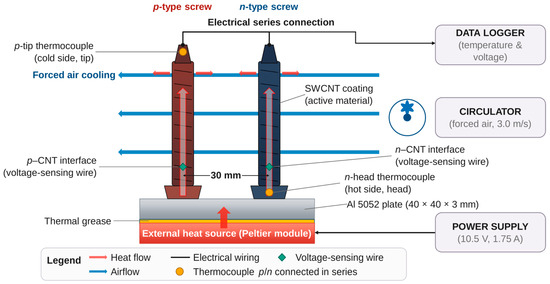
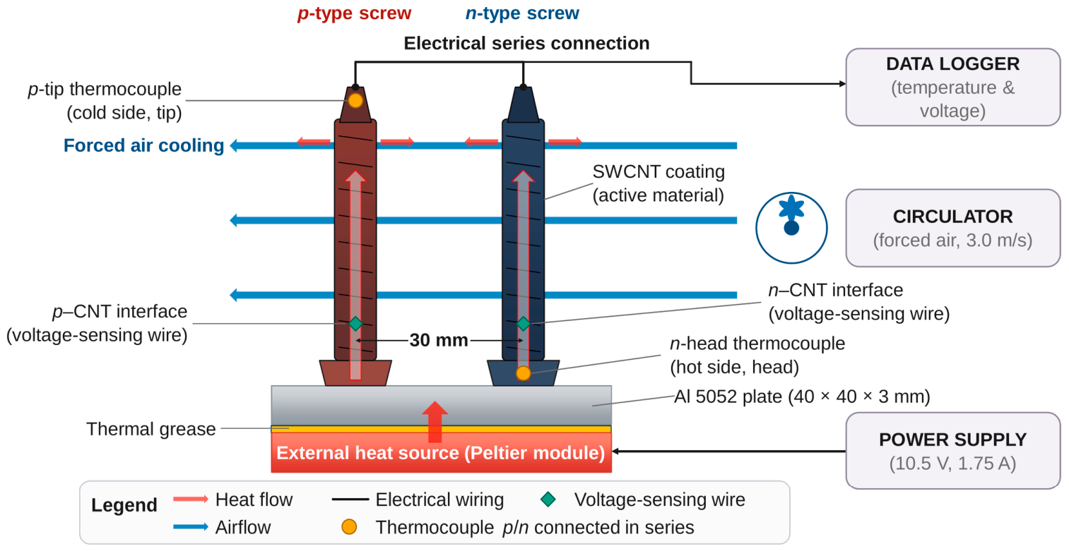
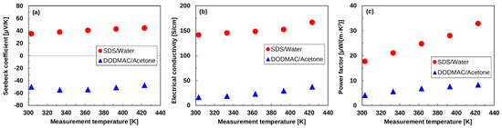
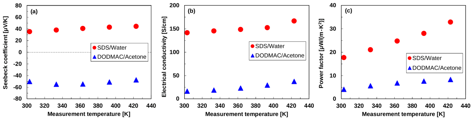
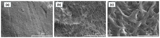
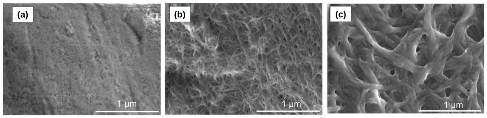
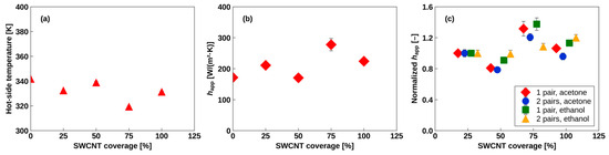
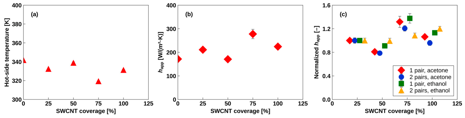
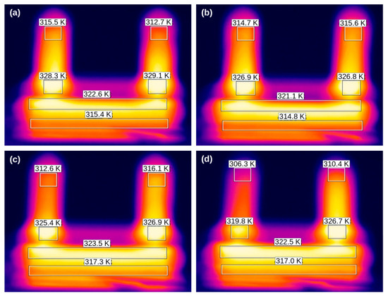
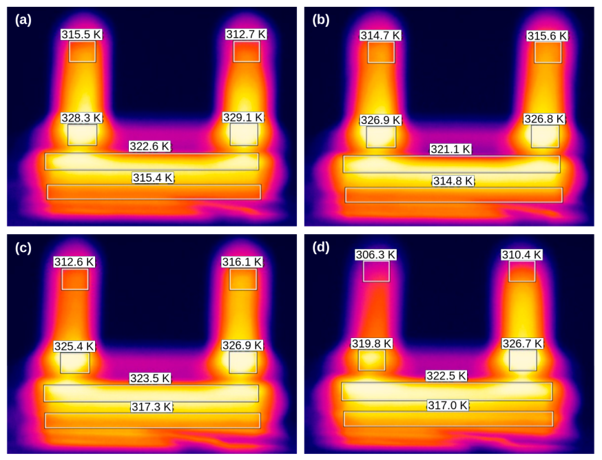
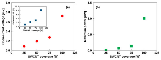
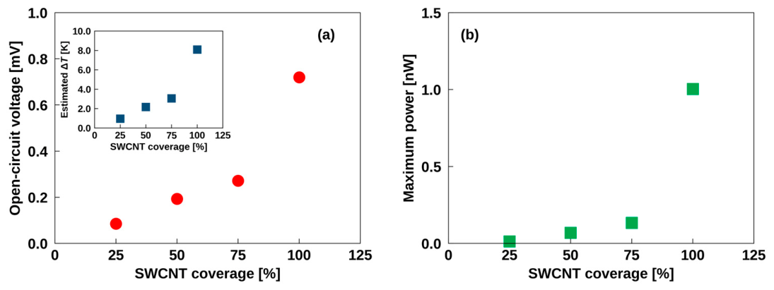
Disclaimer/Publisher’s Note: The statements, opinions and data contained in all publications are solely those of the individual author(s) and contributor(s) and not of MDPI and/or the editor(s). MDPI and/or the editor(s) disclaim responsibility for any injury to people or property resulting from any ideas, methods, instructions or products referred to in the content. |
© 2026 by the authors. Licensee MDPI, Basel, Switzerland. This article is an open access article distributed under the terms and conditions of the Creative Commons Attribution (CC BY) license.