


Abstract
Against the backdrop of increasingly power-electronics-dominated power systems, renewable energy resources are interfaced with the grid through power converters, which are generally categorized as grid-following (GFL) and grid-forming (GFM) converters according to their control principles. The parallel integration of GFL and GFM converters provides a promising solution for balancing system stability, economic performance, and grid-support capability. This paper investigates the transient synchronization instability of hybrid GFL–GFM systems subjected to grid faults. First, the dominant factors affecting the transient synchronization stability of individual GFL and GFM converters are identified, and corresponding stability-enhancement control strategies are developed. Then, considering the dynamic interactions between GFL and GFM converters in the hybrid system, a coordinated control strategy is proposed to enhance the overall transient synchronization stability of the hybrid system. Finally, the effectiveness of the proposed strategy is validated through simulations.
1. Introduction
In recent years, driven by sustainable development policies, renewable energy generation has experienced rapid growth. Renewable energy generation units are interfaced with the power grid through power electronic converters, whose grid-connected control schemes can generally be classified into grid-following (GFL) and grid-forming (GFM) control [1]. GFL control enables maximum power point tracking and fast power regulation and has therefore been widely adopted in practical applications. However, as the penetration of renewable energy continues to increase, the reduction in system inertia and grid strength has led to increasingly pronounced weak-grid conditions. Consequently, grid-connected converters dominated by GFL control face significant challenges in maintaining system stability [2]. In contrast, GFM converters can autonomously establish voltage magnitude and phase and actively support the power grid, thereby exhibiting greater adaptability under weak-grid conditions. Existing international studies have indicated that incorporating GFM converters into renewable energy plants is an effective approach to improving system stability [3]. Consequently, renewable energy plants integrating both GFL and GFM converters are becoming an increasingly prevalent system configuration [4]. By combining the complementary characteristics of the two control modes, such hybrid systems can address the challenges associated with low inertia and weak grids while achieving a desirable balance between system stability and economic performance.
Although hybrid grid-following/grid-forming systems have begun to see practical deployment, the risk of synchronization instability of grid-connected converters during transients, potentially resulting in large-scale disconnection of renewable generation, remains a major concern. Under large-signal disturbances, such as medium-voltage-side line faults and abrupt variations in photovoltaic output, complex dynamic interactions may arise among converter control loops and between converters and weak grids, potentially inducing wideband oscillations and even large-scale generation tripping [5]. In February 2025, an N−2 contingency involving a major transmission corridor in Chile triggered a frequency collapse. A large number of photovoltaic plants in the northern region were disconnected because of insufficient fault-ride-through capability, ultimately causing outages across 14 regions nationwide [6]. In April 2025, photovoltaic generation in Spain reportedly decreased by more than 10.25 GW within 5 min under a high-penetration operating condition, causing severe frequency oscillations and cascading disconnection of synchronous generation and ultimately resulting in a widespread blackout across the Iberian Peninsula [7]. These incidents demonstrate that severe disturbances can cause grid-connected converters to lose synchronization and subsequently disconnect from the grid. Therefore, the synchronization stability of renewable-energy-integrated power systems requires particular attention, and the effects of power-electronic control loops on synchronization stability must be systematically clarified.
At present, research on the transient stability of multi-converter systems remains at an early stage and has primarily focused on homogeneous control configurations. In [8], a stability criterion applicable to large-scale hybrid multi-converter systems was developed based on the small-gain phase theorem, thereby substantially reducing the complexity of system-level analysis. In [9], an impedance-based transfer-function method was proposed for stability assessment and instability-source identification in large-scale systems. In [10], a fourth-order synchronization model of a hybrid system was established, revealing the bidirectional saddle-equilibrium-point effect and the influence of control interactions on synchronization stability. Although these studies have advanced the small-signal stability analysis of hybrid systems, they do not address the interactions associated with transient energy exchange. Linearized methods can provide effective criteria for small-signal stability assessment; however, as demonstrated in [11], cascading collapse in hybrid systems highlights their inherent limitations in capturing large-disturbance dynamics and nonlinear system behavior.
For hybrid GFL–GFM systems, ref. [12] identified the output-current limit of grid-connected converters as a major bottleneck restricting further improvements in transient stability. To address the dimensionality challenge associated with multi-converter systems, ref. [13] proposed a fuzzy tensor-space approach that reduces the computational complexity from exponential to constant order. However, existing studies have generally failed to quantitatively characterize the transient influence of GFM converters on GFL converters. In transient stability analysis of hybrid systems, GFL converters are often simplified as constant current sources, with their dynamic behavior neglected. Under weak-grid conditions, however, GFL converters are more susceptible to loss of synchronism than their GFM counterparts [14]. In [15], a phase-plane method was employed to assess the fault-induced transient behavior of a hybrid system, but a complete analytical stability criterion was not established. Although [16] investigated the impact of GFL converters on GFM converters using an extended equal-area criterion, the reverse influence of GFM converters on GFL converters was neglected. Therefore, the transient synchronization stability of hybrid grid-connected systems and the underlying mechanisms of control interactions remain to be systematically investigated.
To enhance the synchronization stability of power systems with a high penetration of renewable energy, this paper investigates the nonlinear loss-of-synchronism mechanisms of grid-connected converters and the synchronization-control interactions among heterogeneous converters in hybrid GFL–GFM systems. The main contributions are summarized as follows.
- To address the transient instability of GFL converters caused by negative equivalent damping of the phase-locked loop (PLL) under large grid disturbances, a structure-adaptive PLL control strategy is proposed to improve transient damping and enhance the synchronization stability of GFL converters.
- A virtual-impedance control strategy is developed for GFM converters to coordinate the competing requirements of overcurrent suppression and voltage stability. The proposed strategy effectively suppresses transient oscillations and enhances the low-voltage ride-through capability of GFM converters.
- A phase-coordinated control strategy is proposed to mitigate the transient interactions induced by power-angle coupling, thereby enhancing the overall transient synchronization stability of the hybrid GFL–GFM system.
The three contributions form a progressive framework from individual-converter stability enhancement to system-level coordinated control. The first two contributions improve the transient synchronization stability of GFL and GFM converters, respectively. Building on these developments, the third contribution integrates the proposed control strategies into a hybrid GFL–GFM system and introduces phase-coordinated control to mitigate converter interactions and enhance overall transient synchronization stability.
The remainder of this paper is organized as follows. Section 2 introduces the hybrid grid-connected GFL–GFM system and establishes its mathematical model. Section 3 presents the synchronization stability enhancement strategy for the GFL converter. Section 4 presents the synchronization stability enhancement strategy for the GFM converter. Section 5 introduces the coordinated control strategy for the hybrid system. Section 6 validates the effectiveness of the proposed control strategies through simulations. Finally, Section 7 concludes the paper.
2. Description of the Hybrid Grid-Connected GFL–GFM System
2.1. Description of the Hybrid Grid-Connected System
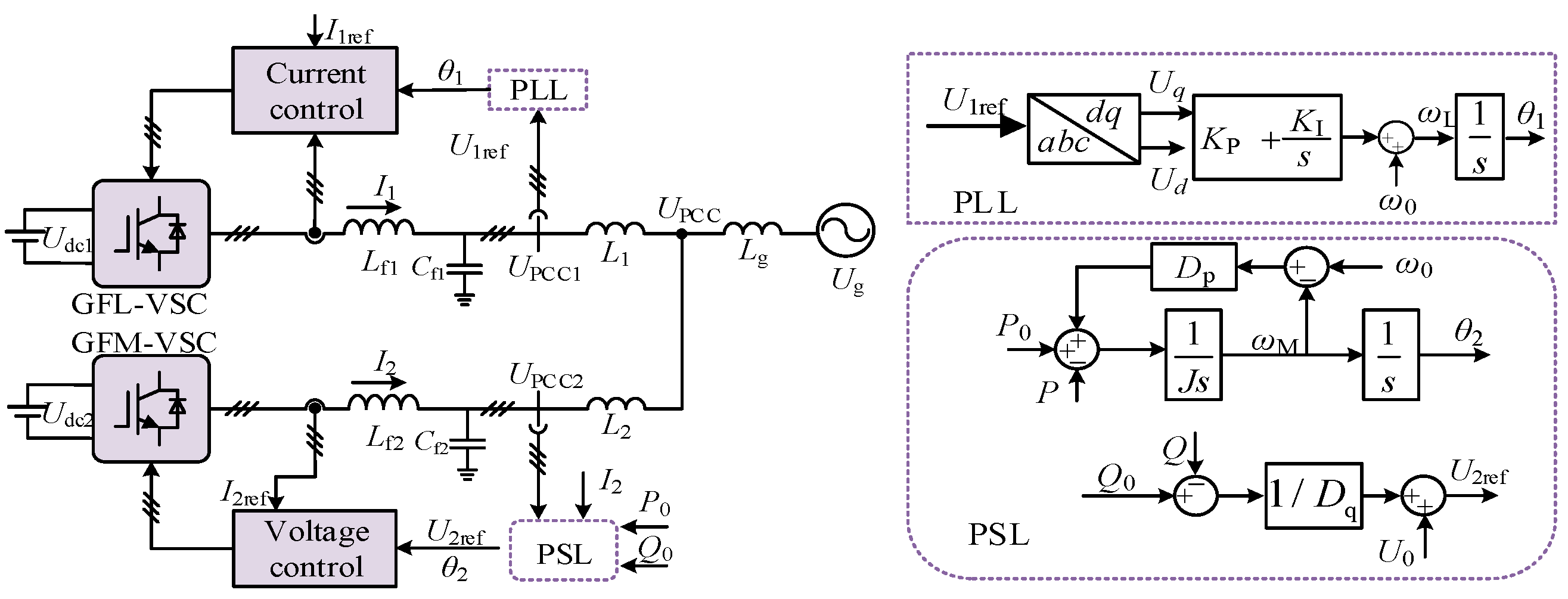
The hybrid grid-connected system composed of grid-forming and grid-following converters can provide strong grid adaptability while maintaining high power-generation efficiency, and thus offers broad application prospects for enhancing the stability, reliability, and flexibility of future power systems. Figure 1 shows a typical topology of a hybrid grid-connected system comprising grid-forming and grid-following converters. In this system, the grid-following converter acquires the reference frequency and phase angle from the PCC voltage UPCC1 through a phase-locked loop (PLL), whereas the grid-forming converter generates its reference phase angle through a power synchronization loop (PSL) based on the power at UPCC2. Here, Ug and θg denote the grid voltage and grid phase angle, respectively; Lg denotes the grid impedance; U1 and U2 denote the output voltages of the GFL and GFM, respectively; I1 and I2 denote their output currents; and θ1 and θ2 denote their respective output reference angles. The control block diagrams of the PLL and PSL are shown in Figure 1, where ω0 is the rated angular frequency of the system, i.e., the grid angular frequency; KP and KI are the proportional and integral gains of the PI controller in the PLL; P and Q are the active and reactive powers injected by the grid-forming converter into the system; P0 and Q0 are the corresponding reference values; U0 is the rated voltage; J is the virtual inertia; Dp is the damping coefficient; kq is the reactive-power droop coefficient; and the subscript “ref” denotes the reference value.
Figure 1.
Topology of the Hybrid Grid-Connected GFL–GFM Converter System.
In the hybrid system, the inherent mismatch between the grid-forming operation of the GFM converter and the tracking-based synchronization of the GFL converter leads to dynamic interactions between the PLL tracking behavior and the autonomous voltage-regulation objective of the GFM converter. Consequently, the transient stability of the system is jointly determined by the interactions between the GFL and GFM converters.
2.2. Modeling of the Hybrid Grid-Connected System
In a typical GFL converter, the time scales of the current control loop and the PLL are approximately 10 ms and 100 ms, respectively [12]. In a GFM converter, the time scale of the power control loop is approximately 2 s, which is much slower than that of the inner voltage control loop [17]. For an individual converter, a time-scale separation assumption is commonly adopted, under which the fast inner-loop dynamics are assumed to have reached steady state. The corresponding differential equations can therefore be replaced by algebraic constraints, thereby reducing the model complexity. Accordingly, the GFL and GFM converters can be represented as a controlled current source and a controlled voltage source, respectively.
The phase-angle differences of the GFL and GFM converter output voltages with respect to the grid voltage are defined as and, respectively, i.e.,
When the two converters are connected to the grid, the PCC voltage can be expressed as follows:
In Equation (2), the first term represents the dynamic component of the PCC voltage associated with the variation of the GFL phase angle, whereas the second term represents the static network-voltage component determined by the GFM output voltage and the grid voltage.
The GFL converter employs a PLL-based synchronous reference frame, in which the three-phase voltage UPCC1 is transformed into the dq0 frame, with the q-axis voltage serving as the input to the PI controller. Accordingly, δ1 can be expressed as follows:
UPCC1 can be expressed as follows:
where , , .
The q-axis component of UPCC1 is given by:
where denotes the phase angle of the injected current relative to the PLL angle.
The equation reveals the existence of coupling terms between the GFM and GFL converters. Since the PSL of the GFM converter responds more slowly than the PLL of the GFL converter, the transient behavior of the interconnected system is dominated by the GFM converter. Consequently, after a GFM converter is integrated into a renewable-energy power plant, the originally GFL-controlled system exhibits certain grid-forming characteristics.
The second-order differential equation of the GFL converter is given by:
Under the influence of the synchronization controls, the frequencies of the GFL and GFM converters may differ. The active and reactive powers, P and Q, delivered by the GFM converter at its point of connection are given by:
Based on the control structure of the GFM converter shown in Figure 1, the active-power dynamics can be derived as follows:
where b0 = P0/ω0, b1 = 1.5U2Ug/(L2 + Lg)ω0, b2 = 1.5U2I2Lg/(L2 + Lg)ω0.
Equations (6) and (8) together constitute the nonlinear mathematical model of the hybrid system shown in Figure 1.
The above analysis of the coupling terms indicates that, during a grid-voltage sag, the main challenges faced by the hybrid system include the individual synchronization stability of the grid-following and grid-forming converters, as well as the risk of power-angle instability caused by power imbalance between the two converters.
To address the above issues, an adaptive-impedance method is first incorporated into the grid-following control scheme to enhance individual synchronization stability. Second, an improved power-loop control strategy is proposed to achieve coordinated transient power regulation of the grid-forming converter. To address overcurrent and voltage-support requirements, the virtual-inductance method in the VSG control algorithm is further extended to a virtual-impedance method, thereby effectively suppressing transient current surges and providing reactive-power-based voltage support. Finally, a phase-coordination control strategy is introduced to mitigate the transient interactions caused by power-angle coupling terms and enhance the transient synchronization stability of the hybrid system.
3. Design and Analysis of the Adaptive PLL
The modeling analysis presented in the previous section indicates that ensuring the synchronization stability of the GFL converter is essential for achieving transient synchronization stability of the hybrid system. To enhance the transient stability of the GFL converter, an adaptive PLL control strategy is proposed based on qualitative analysis.
The dynamic equations governing the PLL can be expressed as follows
where the power angle is defined as δ = θL − θg, and θL denotes the reference angle generated by the GFL converter. Kp and KI are the proportional and integral gains of the PI controller within the PLL.
Based on (9), the nonlinear PLL model can be derived as follows:
By analogy with the rotor swing equation of a synchronous generator, the virtual power-angle swing equation can be expressed as follows:
where H denotes the equivalent inertia time constant, Pm represents the equivalent mechanical power, is the equivalent electromagnetic power, denotes the equivalent damping term, and is the angular frequency of the converter output voltage. It should be noted that (11) contains a nonlinear damping coefficient Deq, which may become negative. When , Deq becomes negative. The equivalent mechanical power, equivalent maximum electromagnetic power, equivalent inertia time constant, and equivalent damping coefficients are respectively given by:
When subjected to large disturbances, a grid-following converter equipped with a conventional phase-locked loop may enter an operating region in which the equivalent damping coefficient satisfies D < 0. This negative-damping effect causes the time derivative of the system energy function to become positive, i.e., dV/dt > 0, thereby adversely affecting stable system operation. Although the equivalent damping can theoretically be passively increased by tuning the proportional gain Kp, the integral gain KI, or grid parameters such as Lg, such parameter adjustments inevitably affect the dynamic responses of the AC- and DC-side power and cannot fundamentally eliminate the physical mechanism responsible for negative damping.
Based on the above analysis, if the integral action of the PLL is actively disabled, the system can maintain nonnegative equivalent damping as long as the power-angle deviation δ remains within ±π/2, thereby suppressing instability-induced divergence. However, when the grid frequency deviates from its nominal value, a purely first-order PLL cannot achieve zero-steady-state-error phase tracking, resulting in a persistent phase-tracking error. To simultaneously ensure transient stability and steady-state tracking accuracy, an adaptive PLL control architecture with a mode-switching mechanism is developed in this section, as illustrated in Figure 2. The switching logic is defined as follows. When the equivalent damping of the converter following a disturbance satisfies (D > 0), the system operates in the conventional second-order PLL mode with the integral path enabled. Under a severe disturbance, if the power angle exceeds the maximum allowable deviation δmax, causing the equivalent damping to become negative, i.e., (D < 0), the integral path is immediately disabled. The PLL is then switched to the first-order operating mode to enforce positive damping and prevent transient divergence.
Figure 2.
(a) Block Diagram of the Adaptive PLL Control. (b) Switching Logic of the Adaptive PLL.
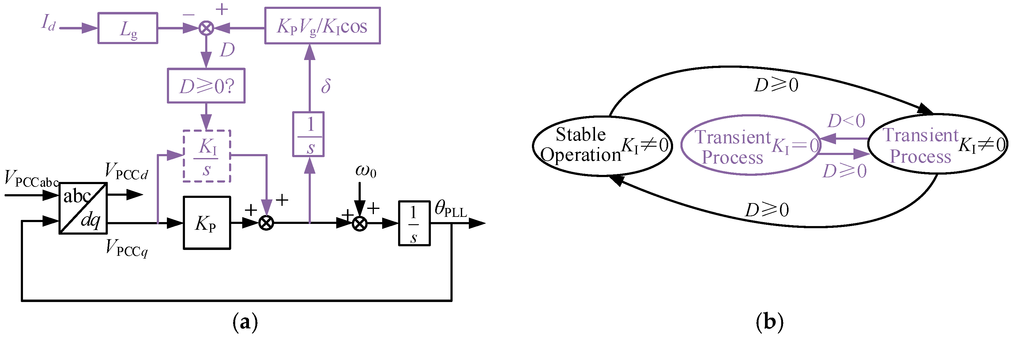
Once the system switches to the adaptive first-order PLL mode, both the internal control structure and the phase-angle dynamics undergo fundamental changes. Under the reconfigured control architecture, the kinetic- and potential-energy terms of the system are reformulated, based on which a new energy function is established. According to the adaptive PLL structure, the dynamic equation governing the PLL power angle δ can be derived as follows:
Accordingly, the second-order differential equation governing the PLL dynamics can be derived as follows:
where .
The kinetic energy Ek2 and potential energy Ep2 of the adaptive PLL can therefore be defined, respectively, as follows:
The energy function of the adaptive PLL can then be further derived as follows:
Based on (11) and (13), the time derivative of the energy function for the adaptive PLL can be derived as follows:
It follows from (17) that the time derivative of the energy function of the improved system is always nonpositive, thereby preventing unbounded energy growth and suppressing the associated divergence.
When D > 0, the system exhibits positive damping and , indicating that the transient energy is continuously dissipated and the oscillations decay. In contrast, a negative D corresponds to negative damping, which would cause the oscillation amplitude to increase if no corrective action were taken. Under the proposed adaptive PLL, however, the corresponding control action is activated when D < 0, resulting in and thereby preventing further energy accumulation. Therefore, the time derivative of the energy function of the improved system remains nonpositive, which suppresses the divergence associated with negative damping.
4. GFM Synchronization Stability Enhancement Strategy
4.1. Improved GFM Power-Loop Control Strategy
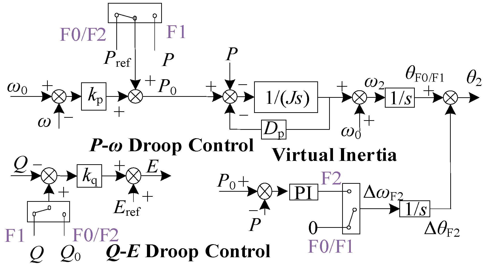
To coordinate the active- and reactive-power control of the grid-forming converter during grid-voltage sags and improve its transient support capability and recovery speed, the power-control loops are optimized in this section, and an improved power-loop control strategy with adaptive operating-mode switching is proposed.
Under conventional VSG control, if the inertial loop continues regulating the active power to track its reference during a voltage sag, the relatively slow dynamic response may prevent the active power from reaching its target throughout the transient period. This regulation process causes the power angle to vary continuously, thereby affecting the reactive-power output capability, potentially impeding grid-voltage recovery and even increasing the risk of overvoltage. In addition, the fixed-parameter reactive-power droop loop may restrict the reactive current that the VSG can inject into the grid during a voltage sag. Based on the above analysis, the core improvements of the proposed strategy are summarized as follows.
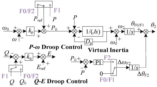
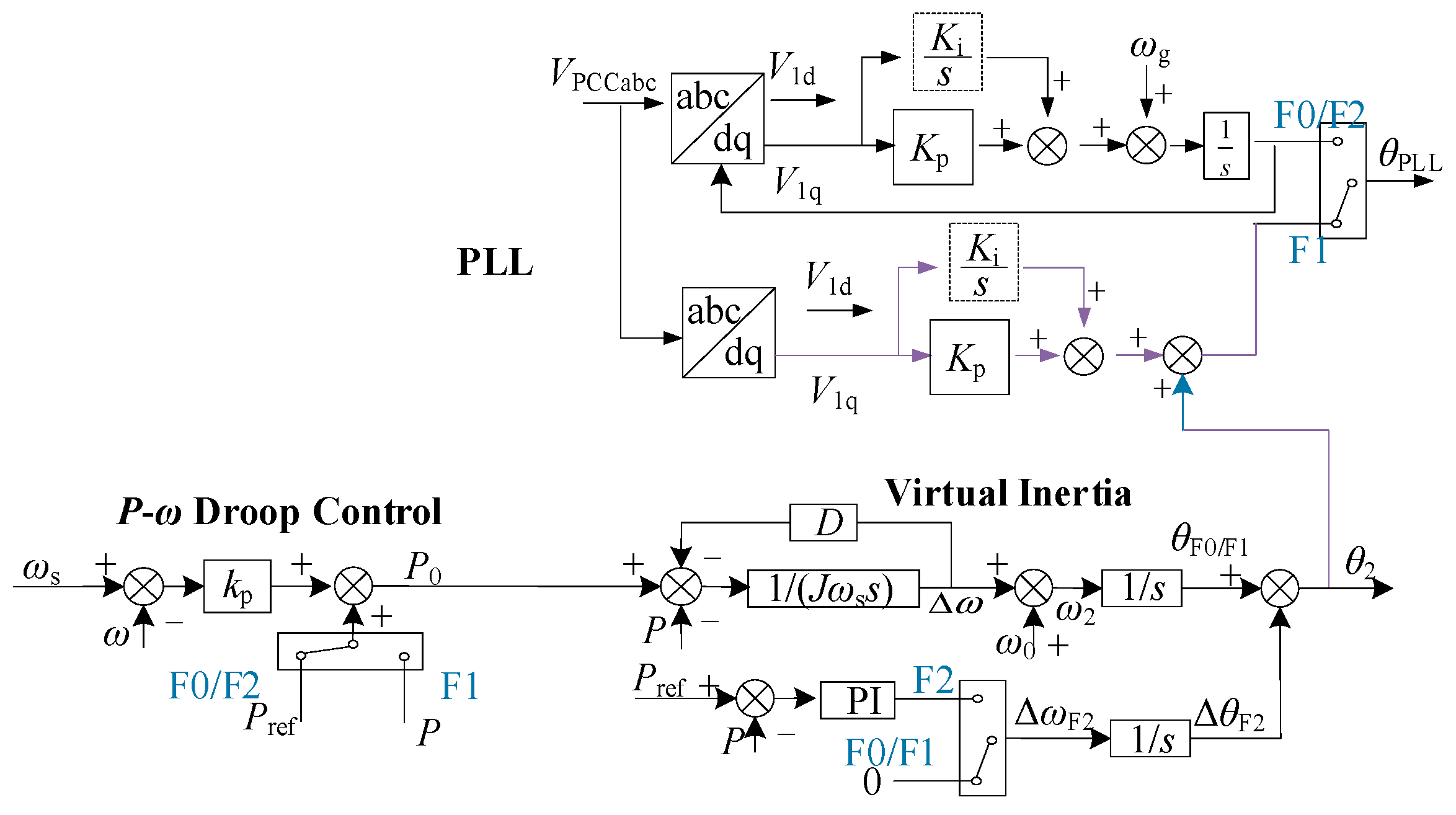
As shown in Figure 3, the operating process is divided into three stages according to the grid-fault condition: F0 represents the pre-fault stage, F1 represents the fault-on stage, and F2 represents the post-fault recovery stage.
Figure 3.
VSG Power-Loop Design.
First, the active-power reference is frozen. Once a grid-voltage sag is detected, the active-power reference is immediately frozen. The VSG then maintains operation based on the power angle immediately before the voltage sag, thereby avoiding the adverse effects caused by delayed active-power regulation.
Second, the reactive-power control mode is switched. During the voltage transient, the reactive-power control is switched from the conventional droop-control mode in F0 to a current-reference mode determined by the virtual impedance in F1. In this mode, the original reactive-power droop coefficient is set to zero, and an additional reactive-current reference is introduced to ensure that the VSG rapidly injects reactive current in compliance with grid-code requirements specified in the Chinese grid code for photovoltaic power stations, GB/T 19964-2024 [18], thereby effectively supporting the grid voltage.
Third, a coordinated recovery mechanism is introduced. Once the grid voltage is detected to have recovered to its normal range, the system exits the transient operating mode, and both the active- and reactive-power loops return to the conventional droop-control mode. If the grid frequency deviates during the voltage sag, a compensation angle , generated by applying PI regulation to the active-power error, is superimposed on the output phase angle of the virtual-inertia loop. This accelerates the coordinated recovery of the system power and frequency and shortens the transient recovery time. Meanwhile, to preserve the normal operating characteristics of the VSG, the auxiliary virtual-inertia loop is removed after the system returns to normal operation. Therefore, after the grid voltage recovers, the recovery mode F2 automatically switches to the normal operating mode F0.
4.2. GFM Fault-Current Control Strategy
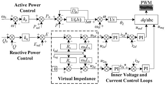
During severe grid-voltage sags, the grid-forming converter faces the dual challenges of excessive transient current and power-angle instability. Introducing virtual resistance rapidly limits the magnitude of the fault current, thereby protecting the converter. Meanwhile, by regulating the converter terminal voltage, the virtual resistance mitigates the abrupt reduction and imbalance in active power, suppresses virtual-rotor acceleration and power-angle divergence, and thus preserves transient power-angle stability while limiting the transient current surge [19].
Suppressing the transient current surge requires a sufficiently large virtual impedance. However, increasing the impedance lowers the power-angle characteristic, thereby increasing the risk of power-angle instability. Therefore, this paper derives the stable operating region of the output impedance to ensure that the transient current is limited to an acceptable range while the system remains stable throughout the power-angle swing.
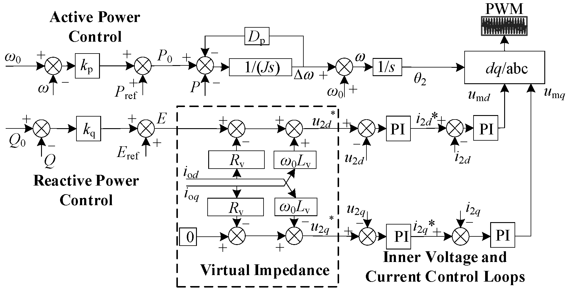
The block diagram of the virtual-impedance control strategy is shown in Figure 4.
Figure 4.
The block diagram of the virtual-impedance control strategy.
After the virtual impedance is introduced, the output impedance is no longer purely inductive, and the power-angle characteristic can be expressed as follows:
where Ug is the grid voltage, U2 is the VSG output voltage, δ2 is the power angle, Zv is the virtual impedance, and θv is the virtual-impedance angle.
Therefore, the power-angle swing equation can be expressed as follows:
According to (19), the power angle can be expressed as follows:
To ensure the existence of an equilibrium point, the power angle must first satisfy the following condition:
Combining this result with (21), the output-impedance constraints before and after the disturbance can be obtained, respectively, as follows:
where Ug0 is the initial grid voltage and Usag is the grid voltage during the fault.
Under virtual-impedance control, and neglecting the delay of the current-control loop, the output current can be expressed as follows:
where Zv, Rv, and Xv denote the virtual impedance, virtual resistance, and virtual reactance, respectively; θv is the virtual-impedance angle; and ud and uq are the d- and q-axis voltage components in the dq reference frame, respectively. Applying the inverse Park transformation, the α-axis current can be obtained as follows:
By setting , the instant at which the current reaches its maximum can be obtained as follows:
Assuming that the maximum current withstand capability of the converter is ksIref, where ks is the overcurrent coefficient, the peak current must satisfy the constraint iαmax < ksIref. Accordingly, the impedance constraint during the electromagnetic transient can be derived as follows:
In addition, power-angle stability must be maintained throughout the transient process. Based on the Lyapunov energy-function method, the energy function during the transient response is defined as follows:
where δsag is the power angle after the voltage sag. This energy function has a clear physical interpretation and provides a stability assessment that closely approximates the actual stability region.
Substituting the initial point and the critical maximum point into the energy function yields the initial energy V0 and the critical energy Vcr, respectively. According to Lyapunov’s theorem, the stability condition is Vcr − V0 > 0. Therefore, the impedance constraint required to ensure transient power-angle stability can be derived as follows:
According to (22), (25), and (28), the allowable range of the virtual impedance under large disturbances can be determined.
In addition, the reactive-current requirement must also be satisfied. By varying the reactive current IQ, the resistance-to-reactance ratio of the virtual impedance is adjusted to achieve a smooth transition of the virtual impedance. Therefore, following a grid-voltage sag, IQ is set to vary as follows:
where IQs is the reactive current required by the national grid code, τQ is the reactive-current decay coefficient, and tF denotes the instant at which the grid-voltage sag occurs, .
Following the voltage sag, the virtual impedance to be introduced, denoted by ZvF1, can be determined from (22), (25), (28), and (29). With this virtual impedance, the system remains stable throughout the large-disturbance transient. Once the terminal voltage is detected to have recovered to its normal range, the virtual impedance is gradually restored to its pre-disturbance steady-state value Zv using a ramp-control method, thereby recovering the optimal power-transfer capability and power-control performance. Therefore, by reshaping the virtual impedance of the grid-forming converter within the derived stable operating region, stable operation under large disturbances can be maintained while transient current surges are effectively suppressed.
In addition, to suppress the current surge caused by the electromagnetic transient during grid-voltage recovery, a virtual resistance RvC must be designed for the recovery stage. Denoting the total current during grid-voltage recovery by the vector IoR, its magnitude IoR can be expressed as follows:
where ioRd and ioRq comprise both transient- and steady-state current components. Since the three-phase currents can be regarded as the projections of the resultant current vector IoR onto the three-phase coordinate system, none of the phase currents will exceed its limit as long as the magnitude of IoR remains within the allowable range. Because the steady-state current IoRs is 1 p.u., the recovery strategy is designed to limit IoR to no more than 1 p.u., thereby ensuring a smooth transition to the steady state. Based on this objective, the virtual resistance introduced during the recovery process is designed accordingly.
After the virtual resistance RvF2 is introduced, the relationship between the voltage and current can be expressed as follows:
where uF2d and uF2q are the d- and q-axis components, respectively, of the voltage uF2 during grid-voltage recovery.
Based on the objective of maintaining IoR at 1 p.u., the expression of the virtual resistance RvF2 can be derived as follows:
The virtual resistance RvF2 is determined from the real-time measured GFM output voltage uF2. Accordingly, RvF2 can be adaptively adjusted according to the measured voltage to prevent excessive transient current surges. According to circuit theory, the transient current component essentially decays to zero after four time constants. Therefore, after RvF2 is maintained for four time constants τcon, i.e., Tcon = 4τcon, it can be gradually reduced to zero, where τcon is:
Once the transient current component has substantially decayed, the virtual resistance RvF2 must be gradually reduced to zero. Therefore, the virtual resistance RvC is defined as follows:
where tc denotes the instant of grid-voltage recovery, and τde is the time constant governing the decay of the virtual resistance RvC0.
To minimize the recovery time, the virtual resistance should decay to zero as rapidly as possible after suppressing the electromagnetic transient current, after which the active- and reactive-power control loops are restored to accelerate the completion of the electromechanical transient. Since the peak current during the electromagnetic transient generally occurs within half a fundamental-frequency cycle, it is sufficient for the virtual resistance RvC to decay to zero within 0.01 s. Therefore, τde is set to:
TCON denotes the duration for which the virtual resistance RvF2 is maintained and is constrained to 0 < TCON < 0.01s. This constraint ensures that the virtual resistance completes its holding and decay process within half of a fundamental-frequency cycle while maintaining τde > 0. Because the electromagnetic transient lasts only for a short period, the virtual resistance RvC rapidly decreases from its initial value RvF2 to zero.
5. Coordinated Control Strategy for the Hybrid System
5.1. Transient Power-Angle Coordinated Control
In the hybrid system, the power angle δ1 and output current I1 of the grid-following converter, together with the power angle δ2 and output voltage U2 of the grid-forming converter, are mutually coupled through the PCC. Consequently, it is difficult to regulate the power angles by independently adjusting the output of each converter. Therefore, coordinated control is introduced into the power-angle control of the two converters to mitigate their control interactions.
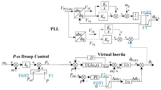
Specifically, the output phase angle θ2 of the grid-forming converter is transmitted to the PLL. A constant angular difference ϕ exists between U1 and the d-axis of the grid-forming converter. Therefore, an additional angle ϕ must be superimposed on θ2 to obtain the reference angle for the grid-following converter. This angle is generated by measuring the deviation of u1q and applying PI regulation, as follows:
Based on (36), an improved PLL control strategy referenced to the phase angle of the grid-forming converter can be obtained, namely, the transient power-angle coordination control strategy. Compared with the PLL-based synchronization of the GFL converter, the GFM converter can autonomously establish its frequency and therefore exhibits stronger adaptability under weak-grid conditions. By acquiring the phase-angle information generated by the power synchronization loop of the GFM converter, the GFL converter can exhibit certain grid-forming characteristics, thereby enhancing its synchronization stability. On the other hand, improving the transient synchronization of the GFL converter enhances its power output, mitigates adverse interactions, and prevents cascading instability caused by transient interactions.
With the grid-forming converter employing the power-loop control strategy with adaptive operating-mode switching, the grid-following converter first adopts adaptive PLL control and then incorporates transient power-angle coordination control. The resulting control block diagrams of the grid-forming and grid-following converters are shown in Figure 5. Under this control scheme, the synchronization stability of the grid-following converter can be ensured as long as the grid-forming converter remains synchronized and stable.
Figure 5.
Transient Power-Angle Coordination Control.
5.2. Coordinated Control Strategy for Transient Stability Enhancement
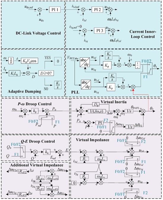
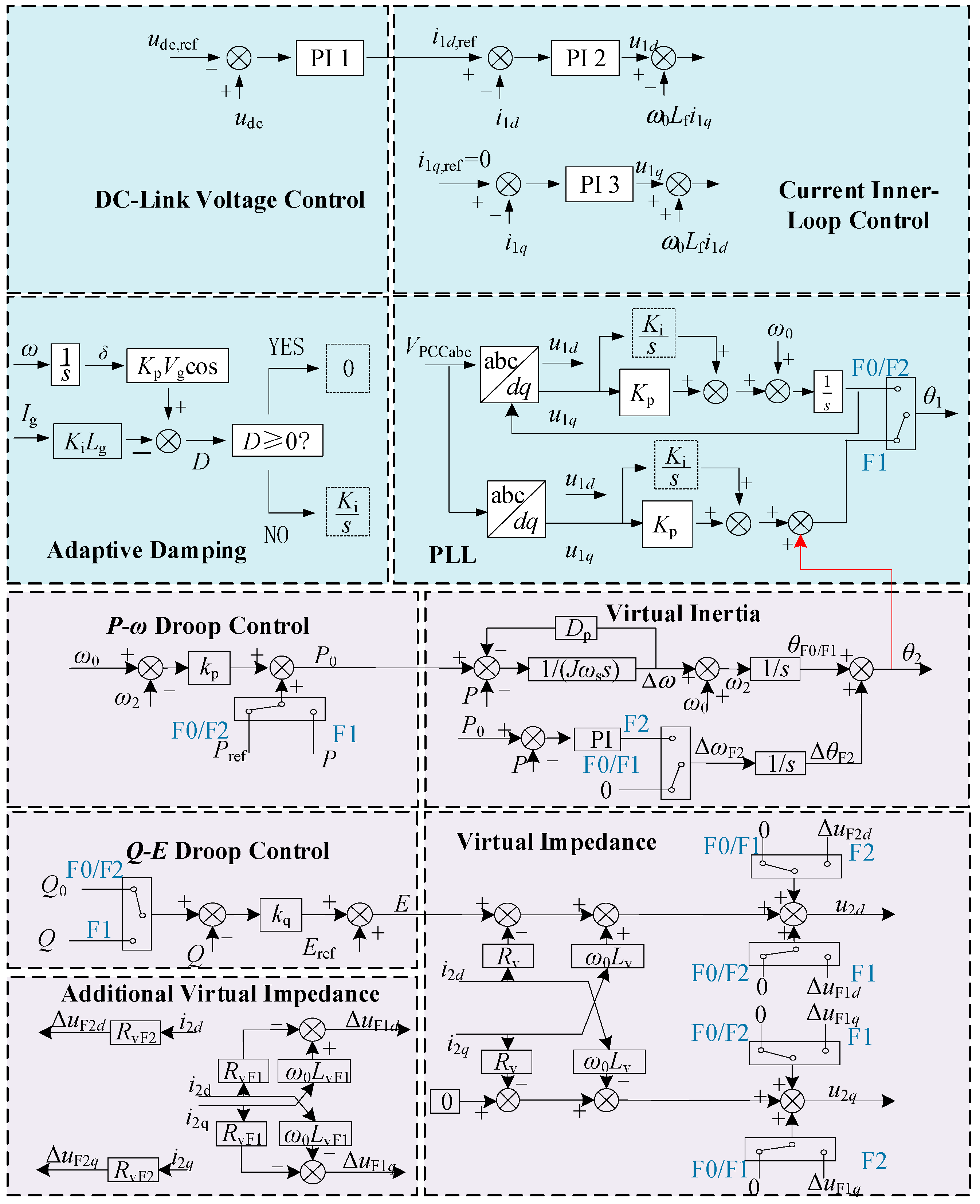
This section proposes a coordinated control strategy for enhancing the transient stability of a multi-converter system, and the overall control block diagram is shown in Figure 6. On the GFM side, a virtual-synchronous-generator-based multimode switching strategy is adopted, including the normal operating mode (F0), fault operating mode (F1), and recovery mode (F2). In the fault operating mode, virtual-impedance control is employed to regulate the fault current and maintain transient power-angle stability. On the GFL side, adaptive damping control is introduced to enhance synchronization stability under weak-grid conditions. In addition, dynamic phase coordination between the GFM and GFL converters is achieved through the transient power-angle control loop.
Figure 6.
Coordinated Control Strategy for the Hybrid System.
In the hybrid system, the synchronization stability of the GFL converter is significantly affected by the grid impedance and the depth of the voltage sag. The GFL converter adopts an adaptive damping control strategy based on real-time detection of the equivalent damping coefficient D. Under normal operation or mild disturbances, D ≥ 0, and the PLL operates in the conventional second-order mode with the integral term retained, thereby ensuring zero steady-state error in phase tracking. When a severe disturbance introduces a risk of instability such that D < 0, the system automatically switches to the adaptive mode, in which the integral term is set to zero and the PLL is transformed from a second-order system into a first-order system. This strategy eliminates the negative-damping effect and enlarges the transient stability region of the GFL converter.
To ensure reliable low-voltage ride-through (LVRT) of the GFM converter during grid faults, its control strategy must properly coordinate the conflicting requirements of transient voltage support and overcurrent suppression. Under normal grid conditions, the system operates in the conventional droop-control mode (F0). Once a grid voltage sag is detected, the controller switches from F0 to the transient support mode (F1). In this mode, the following key measures are adopted. First, the active- and reactive-power control loops are frozen, thereby suspending the regulation of the outer power loops. This measure prevents continuous power-angle deviation and potential instability caused by the relatively slow response of the power-control loops, while providing favorable conditions for accurate reactive-current regulation. It also avoids the adverse influence of the conventional reactive-power droop loop on the injection of inductive reactive current required by the grid code. Second, an additional transient virtual impedance ZvF is introduced. The increased equivalent output impedance suppresses overcurrent caused by the voltage difference across the point of connection. Meanwhile, by appropriately configuring the resistance-to-inductance ratio of the virtual impedance, the phase relationship between the output voltage and current can be adjusted to ensure that the injected reactive current satisfies the grid-code requirements.
When grid-voltage recovery is detected, the controller switches from the F1 mode to the recovery transition mode (F2). In this mode, the following operations are performed according to a predefined sequence. First, the damping resistance is activated with priority. Specifically, the virtual resistance RvC is introduced to suppress the inrush current that may occur immediately after voltage recovery through its damping effect. The virtual resistance is then smoothly withdrawn after the transient current component has decayed. Second, the power-control loops and the virtual-inertia loop are restored with a time delay. After the virtual resistance has been activated and the inrush current has been effectively suppressed, the active-power–frequency droop, reactive-power-voltage droop, and auxiliary virtual-inertia loops are re-enabled. This delayed-recovery strategy prevents adverse regulation of the power-control loops caused by the current surge during the initial recovery stage. The virtual-inertia loop compensates for the accumulated power-angle deviation resulting from the frequency deviation during the fault, thereby facilitating a rapid and smooth transition to steady-state operation. Once the transient process is fully completed, the system automatically switches from the F2 mode back to the F0 mode.
In addition, to achieve synchronous coordination among multiple converter units in the hybrid system, a transient power-angle control loop is introduced. Since the phase angle of the GFL converter terminal voltage is susceptible to fluctuations of the GFM converter under strong interactions, the output phase angle of the GFM converter is introduced into the reference input of the GFL PLL. The dynamic phase-angle deviation between the GFM and GFL reference frames is then calculated and processed by a PI controller to generate a phase-compensation signal for the GFL converter.
The single-GFM/single-GFL hybrid system considered in this study can be regarded as the basic coordination unit of the proposed strategy. For multi-converter renewable-energy plants, the proposed phase-coordination principle can be further extended; for example, each GFL converter may use the phase angle of an electrically associated GFM converter as its transient synchronization reference. The assignment of phase references and coordination among multiple GFM converters will be further investigated in future work.
6. Simulation Validation of Coordinated Control
In this section, MATLAB/SimulinkR2024b simulations are conducted to verify the effectiveness of the proposed coordinated fault-ride-through control strategy for the multi-converter system. The simulation parameters are listed in Table 1.
Table 1.
Simulation Parameters.
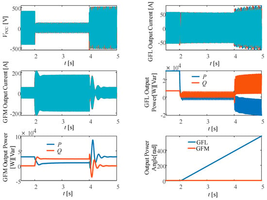
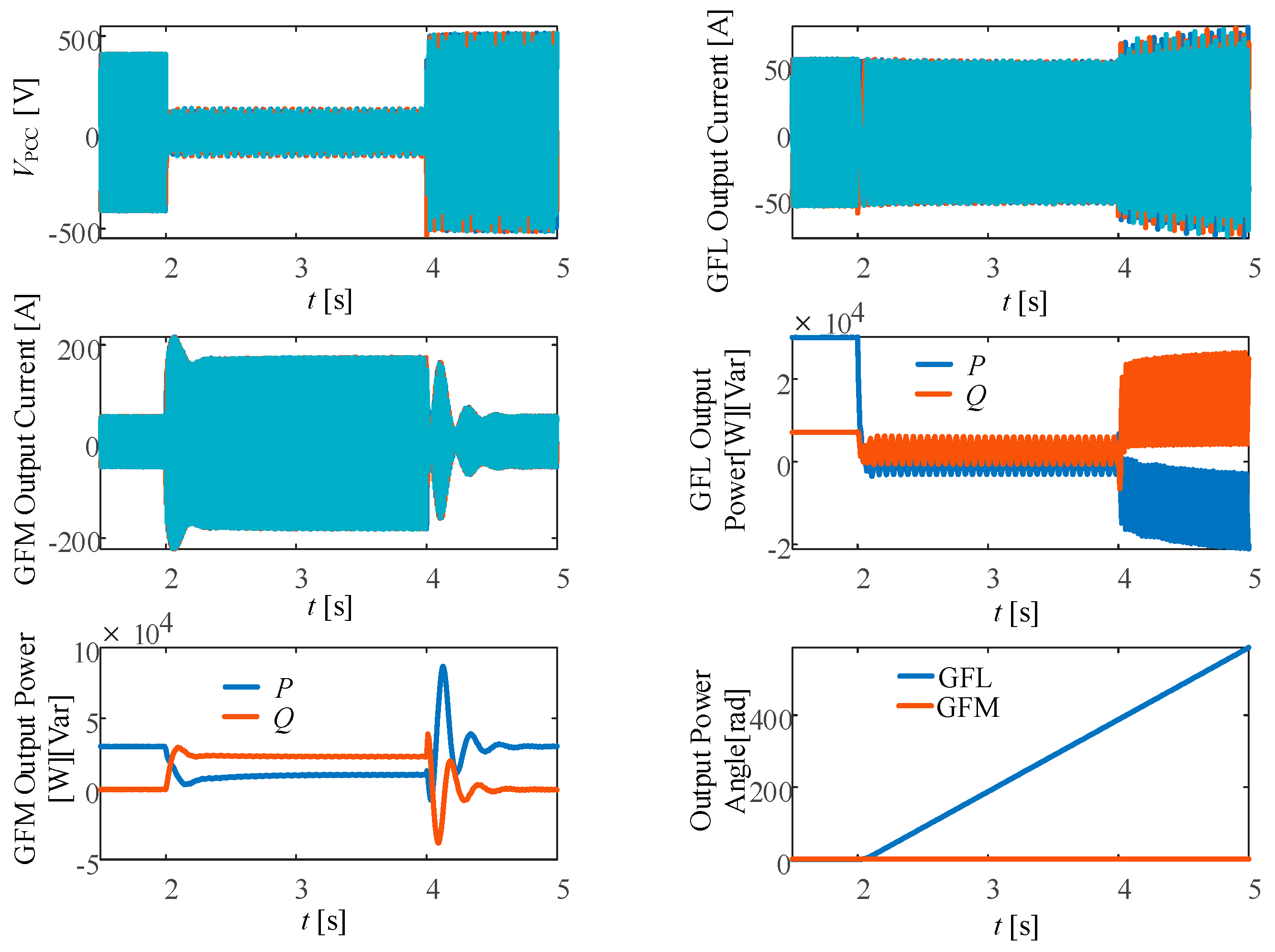
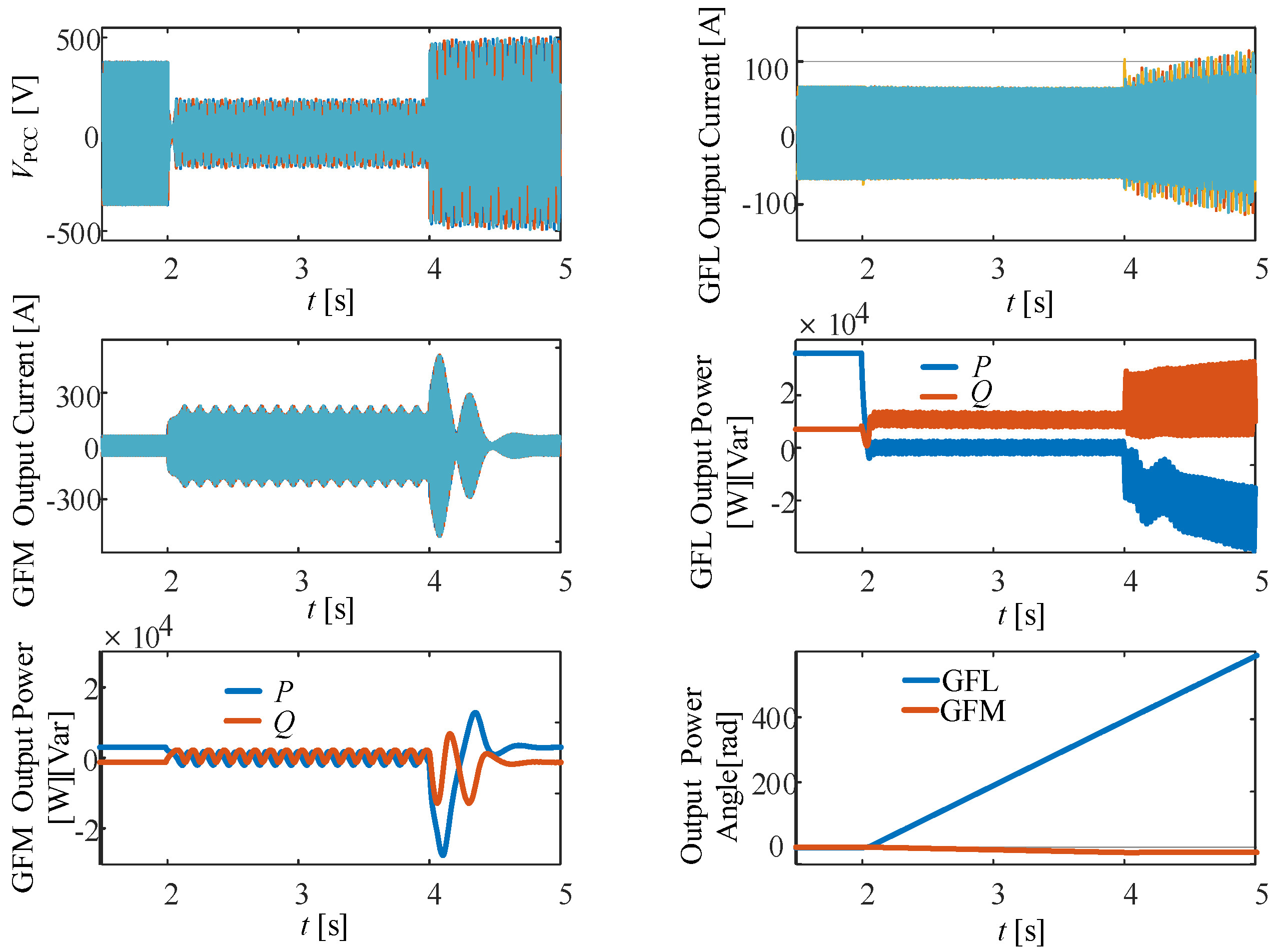
At t = 2 s, an 80% three-phase voltage sag is applied. Figure 7 and Figure 8 show the time-domain responses of the two converters before and after the proposed coordinated fault-ride-through strategy is adopted, including the voltage, current, power, and power-angle responses of the grid-following and grid-forming converters. Without the proposed coordinated control strategy, the system relies solely on the conventional local control of each converter. The simulation results show that the system rapidly loses stability after the fault occurs. The PCC voltage is not effectively supported during the fault, and large damped oscillations arise after fault clearance. The output power of the grid-following converter exhibits divergent oscillations, indicating that the system has lost its stable equilibrium point. Severe overcurrent and waveform distortion occur in the output currents, with peak values far exceeding the allowable limits. These results confirm that, in the absence of optimized individual-converter control and coordinated control, the transient synchronization among the converters cannot be effectively coordinated, ultimately leading to system instability.
Figure 7.
Operating Results Without the Proposed Control Strategy.
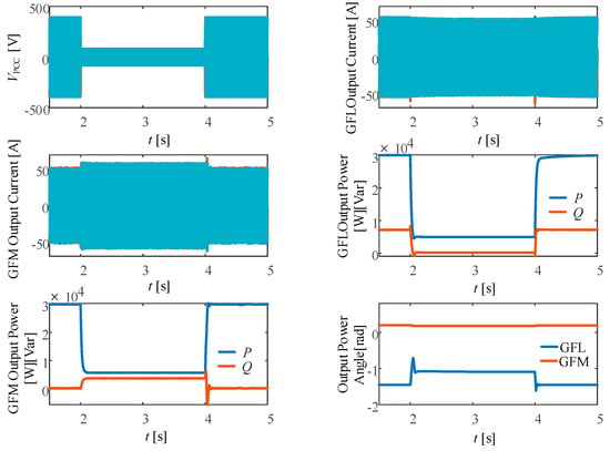
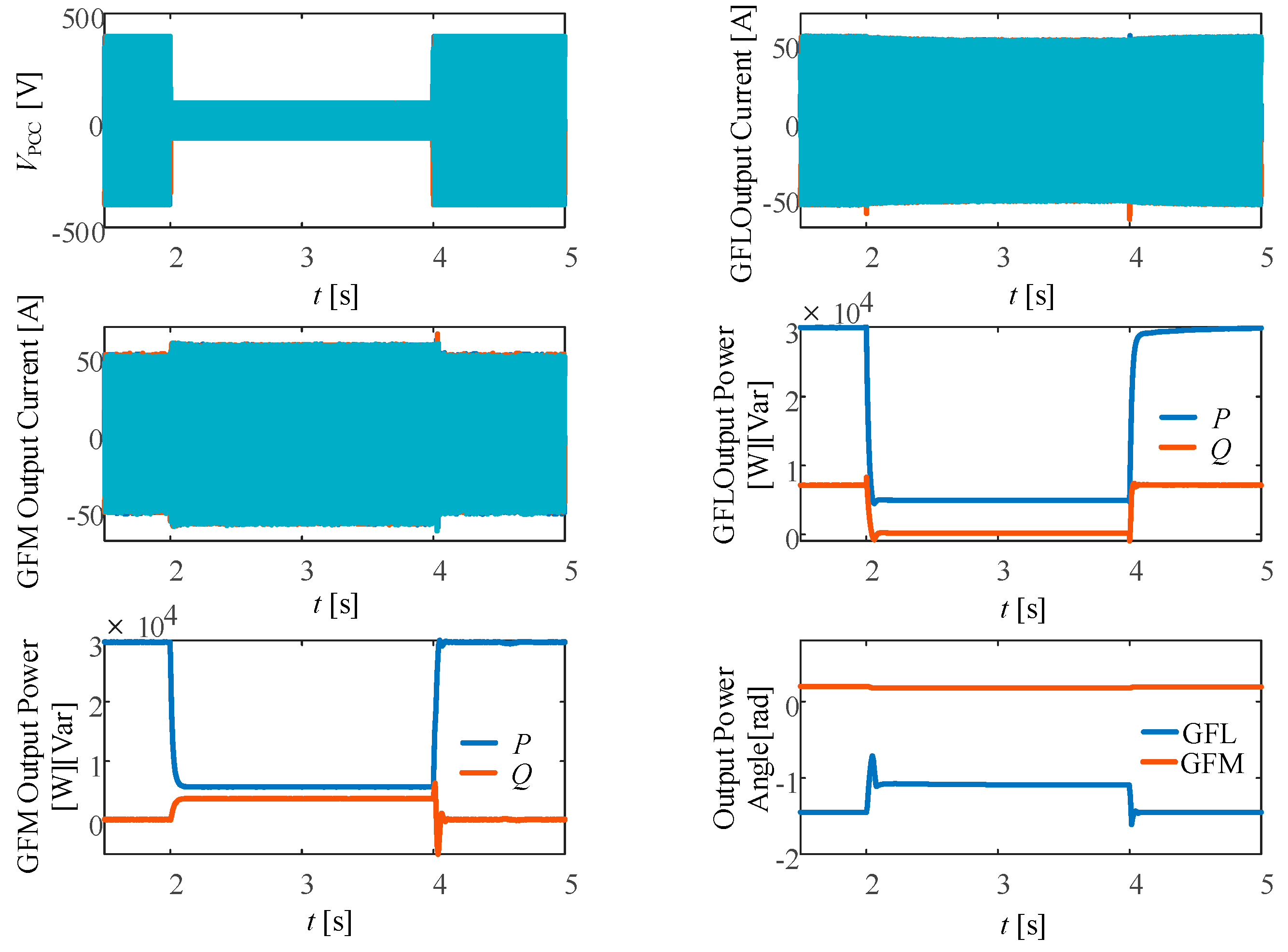
Figure 8.
Operating Results with Coordinated Fault-Ride-Through Control.
With the proposed multi-converter coordinated fault-ride-through control strategy, the system response is substantially improved under the same fault conditions. The simulation results show that the system converges to a stable equilibrium throughout the fault-ride-through process and after fault clearance, thereby maintaining transient stability. The PCC voltage is effectively supported during the fault and smoothly recovers to near its rated value after fault clearance. Although the active and reactive powers of the GFL and GFM converters fluctuate during the transient, they rapidly settle at new operating points, while the output currents of all converters remain strictly within safe limits. The proposed strategy therefore not only preserves transient stability during fault ride-through but also ensures a smooth transition between operating states, substantially reducing the impact of the fault on the system operating schedule and facilitating rapid post-fault power recovery and redispatch.
To further quantitatively evaluate the improvement in transient stability, the critical stable current reference of the GFL was compared under the same fault condition. Under conventional control, the critical value is 50 A, whereas it increases to 63 A with the proposed control, corresponding to an improvement of approximately 26%. Moreover, with the parameters listed in Table 1, the proposed control can maintain transient stability even when the grid voltage drops to 0.16 p.u., indicating that the hybrid system with the proposed control strategy has a relatively large transient stability margin.
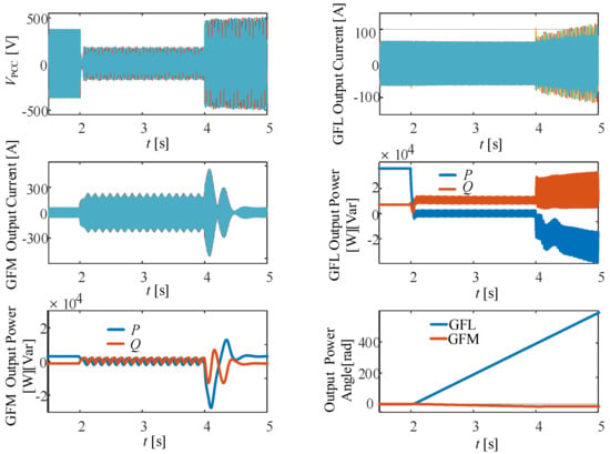
To further verify the effectiveness of the proposed control strategy, a comparison is conducted with the adaptive power reference control method proposed in [12] under the same operating parameters and fault conditions. The corresponding simulation results are shown in Figure 9.
Figure 9.
Simulation results using the control method in [12] under the same operating conditions.
As shown in Figure 9, under the same fault condition, the control method in [12] maintains the synchronization stability of the GFM, whereas the GFL power angle continuously drifts and eventually loses synchronization, resulting in the loss of overall transient synchronization stability of the hybrid system. In contrast, the proposed strategy maintains the synchronization stability of both the GFL and GFM, demonstrating superior transient stability performance.
7. Conclusions
This paper investigates nonlinear synchronization instability in grid-connected converters and synchronization–control interactions in heterogeneous grid-following/grid-forming converter systems. The synchronization mechanisms of GFL and GFM converters are analyzed, and corresponding strategies for enhancing synchronization stability are proposed.
To address the transient instability of GFL converters caused by negative equivalent damping under large disturbances, an adaptive phase-locked-loop control strategy is proposed. To mitigate the transient overcurrent challenge faced by GFM converters during grid faults, a virtual-inductance-based overcurrent suppression strategy is developed. By introducing virtual inductance to reshape the output impedance, the relative positions of the rotor output voltage and transient electromotive force, together with the associated voltage drop, are appropriately adjusted. Consequently, violations of the rotor-voltage and current limits can be rapidly constrained within the allowable converter capacity, thereby reconciling the conflict between grid-forming capability and overcurrent protection.
To address control-interaction coupling in the hybrid system, a coordinated control strategy integrating phase coordination and power optimization is further proposed. The strategy establishes a coordinated framework centered on power-loop control, transient power-angle control, and fault-current suppression. Phase coordination is achieved by introducing the stable phase angle of the GFM converter into the reference input of the GFL converter’s phase-locked loop, while virtual impedance is employed to suppress inrush current.
Simulation results demonstrate that the proposed strategy effectively suppresses power oscillations during both the fault and post-fault recovery periods and enables a smooth transition from fault ride-through to normal operation. The proposed control methods improve the overall transient synchronization stability of the system and provide technical support for the secure and stable operation of renewable-energy power plants.
Author Contributions
Methodology, S.S., M.H., and W.L.; Writing—original draft, Z.W.; Supervision, W.L.; Project administration, W.L. All authors have read and agreed to the published version of the manuscript.
Funding
National Key Research and Development Program of China (2022YFB2402700); Science and Technology Project of State Grid Corporation of China (52272222001J).
Data Availability Statement
The data presented in this study are available on request from the corresponding author.
Conflicts of Interest
The author Wenfei Liu was employed by State Grid Gansu Electric Power Co., Ltd. The funder was not involved in the study design, collection, analysis, interpretation of data, the writing of this article, or the decision to submit it for publication. The remaining authors declare that the research was conducted in the absence of any commercial or financial relationships that could be construed as a potential conflict of interest.
Abbreviations
The following abbreviations are used in this manuscript:
| GFL | Grid-Following Converter |
| GFM | Grid-Forming Converter |
| PLL | Phase-Locked Loop |
| PSL | Power Synchronization Loop |
| SEP | Stable Equilibrium Point |
| UEP | Unstable Equilibrium Point |
References
- Pishbahar, H.; Blaabjerg, F.; Saboori, H. Emerging grid-forming power converters for renewable energy and storage resources integration—A review. Sustain. Energy Technol. Assess. 2023, 60, 103538. [Google Scholar] [CrossRef] [Scilit]
- Yu, C.; Xu, H.; Chen, C.; Sun, M.; Fu, X.; Zhang, X. A Unified Approach to Modeling and Stability Equivalence Analysis for Grid-Forming and Grid-Following Converters. Electr. Power Syst. Res. 2024, 235, 110861. [Google Scholar] [CrossRef] [Scilit]
- Rathnayake, D.B.; Akrami, M.; Phurailatpam, C.; Me, S.P.; Hadavi, S.; Jayasinghe, G.; Zabihi, S.; Bahrani, B. Grid Forming Inverter Modeling, Control, and Applications. IEEE Access 2021, 9, 114781–114807. [Google Scholar] [CrossRef] [Scilit]
- Yang, C.; Huang, L.; Xin, H.; Ju, P. Placing Grid-Forming Converters to Enhance Small Signal Stability of PLL-Integrated Power Systems. IEEE Trans. Power Syst. 2021, 36, 3563–3573. [Google Scholar] [CrossRef] [Scilit]
- Xu, J.; Ling, Z.; Luo, Y.; Kan, J.; Diao, H.; Xie, S. Synchronization Stability Analysis and Parameter Design of Grid-Following Inverters Considering the Interactions of Current Control and Phase-Locked Loop. IEEE J. Emerg. Sel. Top. Power Electron. 2024, 12, 5013–5027. [Google Scholar] [CrossRef] [Scilit]
- Ma, Y. Analysis of the “2.25” Nationwide Blackout in Chile. In Proceedings of the 2025 International Conference on Smart Grid and Energy (ICSGE), Guangzhou, China, 12–14 December 2025; pp. 201–206. [Google Scholar]
- Ortiz, D.; Arrechea, E. Iberian Peninsula blackout: Analysis and performance of Nordex wind power plants. In Proceedings of the 24th Wind & Solar Integration Workshop (WISO 2025), Berlin, Germany, 7–10 October 2026; pp. 904–910. [Google Scholar]
- Huang, L.; Wang, D.; Wang, X.; Xin, H.; Ju, P.; Johansson, K.H.; Dörfler, F. Gain and Phase: Decentralized Stability Conditions for Power Electronics-Dominated Power Systems. IEEE Trans. Power Syst. 2024, 39, 7240–7256. [Google Scholar] [CrossRef] [Scilit]
- Gu, Y.; Li, Y.; Zhu, Y.; Green, T.C. Impedance-Based Whole-System Modeling for a Composite Grid via Embedding of Frame Dynamics. IEEE Trans. Power Syst. 2021, 36, 336–345. [Google Scholar] [CrossRef] [Scilit]
- Lu, D.; Yu, J.; Lu, X.; Yu, J. Synchronization Stability of Hybrid Power Systems Integrated with Grid-Forming Inverters and Grid-Following Inverters. CPSS Trans. Power Electron. Appl. 2024, 9, 405–415. [Google Scholar] [CrossRef] [Scilit]
- Hu, J.; Shan, Y.; Cheng, K.W.; Islam, S. Overview of Power Converter Control in Microgrids—Challenges, Advances, and Future Trends. IEEE Trans. Power Electron. 2022, 37, 9907–9922. [Google Scholar] [CrossRef] [Scilit]
- Me, S.P.; Ravanji, M.H.; Mansour, M.Z.; Zabihi, S.; Bahrani, B. Transient Stability of Paralleled Virtual Synchronous Generator and Grid-Following Inverter. IEEE Trans. Smart Grid 2023, 14, 4451–4466. [Google Scholar] [CrossRef] [Scilit]
- Duan, Z.; Meng, Y.; Zhao, P.; Yan, S.; Wang, X.; Wang, X. Interaction Large-Signal Stability Analysis of M3C and GFM/GFL Hybrid Control Strategies Converters Based on the Novel Fuzzy Tensor Space Method. IEEE Trans. Power Electron. 2025, 40, 9986–9999. [Google Scholar] [CrossRef] [Scilit]
- Aljarrah, R.; Fawaz, B.B.; Salem, Q.; Karimi, M.; Marzooghi, H.; Azizipanah-Abarghooee, R. Issues and Challenges of Grid-Following Converters Interfacing Renewable Energy Sources in Low Inertia Systems: A Review. IEEE Access 2024, 12, 5534–5561. [Google Scholar] [CrossRef] [Scilit]
- Li, M.; Quan, X.; Wu, Z.; Li, W.; Zhu, L.; Hu, Q. Modeling and Transient Stability Analysis of Mixed-GFM-GFL-Based Power System. In Proceedings of the 2021 IEEE Sustainable Power and Energy Conference (iSPEC), Nanjing, China, 22–25 December 2021; pp. 2755–2759. [Google Scholar]
- Shen, C.; Shuai, Z.; Shen, Y.; Peng, Y.; Liu, X.; Li, Z.; Shen, Z.J. Transient Stability and Current Injection Design of Paralleled Current-Controlled VSCs and Virtual Synchronous Generators. IEEE Trans. Smart Grid 2021, 12, 1118–1134. [Google Scholar] [CrossRef] [Scilit]
- Markovic, U.; Stanojev, O.; Aristidou, P.; Vrettos, E.; Callaway, D.; Hug, G. Understanding Small-Signal Stability of Low-Inertia Systems. IEEE Trans. Power Syst. 2021, 36, 3997–4017. [Google Scholar] [CrossRef] [Scilit]
- GB/T 19964-2024; Technical Requirements for Connecting Photovoltaic Power Station to Power System. Standardization Administration of the People’s Republic of China: Beijing, China, 2024.
- Li, M.; Shu, S.; Wang, Y.; Yu, P.; Liu, Y.; Zhang, Z.; Hu, W.; Blaabjerg, F. Analysis and improvement of large-disturbance stability for grid-connected VSG based on output impedance optimization. IEEE Trans. Power Electron. 2022, 37, 9807–9826. [Google Scholar] [CrossRef] [Scilit]

Disclaimer/Publisher’s Note: The statements, opinions and data contained in all publications are solely those of the individual author(s) and contributor(s) and not of MDPI and/or the editor(s). MDPI and/or the editor(s) disclaim responsibility for any injury to people or property resulting from any ideas, methods, instructions or products referred to in the content. |
© 2026 by the authors. Licensee MDPI, Basel, Switzerland. This article is an open access article distributed under the terms and conditions of the Creative Commons Attribution (CC BY) license.