


Abstract
Low-frequency alternating current (LFAC) transmission has attracted increasing attention for medium- and long-distance offshore wind power transmission, as this application scenario is typically characterized by long transmission distance and large installed capacity. Converting offshore low-frequency alternating current into onshore power-frequency alternating current requires a dedicated frequency conversion device. Compared with power–electronic converter-based schemes represented by the modular multilevel matrix converter (M3C), grid connection via a motor–generator pair (M-G) enables the renewable energy port to retain intrinsic synchronous-machine characteristics, including inertial support, voltage support, and fault isolation. This paper elaborates the operating principles and mathematical models of the two types of frequency conversion solution for LFAC transmission systems, and systematically analyzes the frequency support, voltage support, and fault-isolation capabilities of the M-G scheme. Simulation results demonstrate that under a sudden increase in onshore active power load, the M-G system can provide strong frequency support by releasing rotor kinetic energy, and a larger inertia time constant mitigates the frequency drop more effectively. Under a sudden increase in onshore reactive power load, the M-G scheme offers a greater reactive power margin benefiting from its strong short-term overcurrent capability. Moreover, increasing the excitation gain on the motor side and installing shunt reactors at both ends of the submarine cable can effectively improve the voltage profile along the cable.
1. Introduction
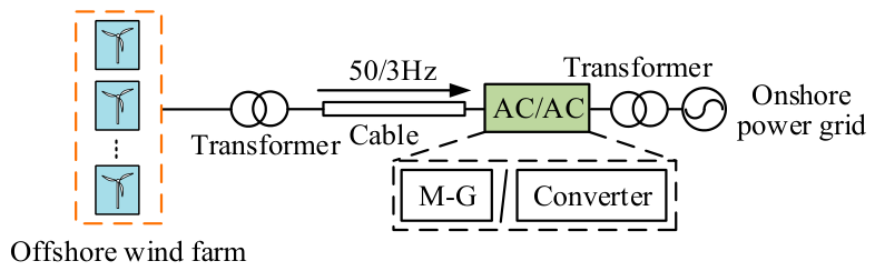
Wind power resources in coastal regions are an important component of clean energy systems [1,2,3]. To transmit offshore wind power to onshore power-frequency grid, three technical schemes are commonly adopted: voltage source converter-high voltage direct current (VSC-HVDC) transmission, low-frequency alternating current (LFAC) transmission, and power-frequency alternating current transmission [4]. Compared with VSC-HVDC transmission, LFAC transmission requires less complex and less costly offshore platform equipment [5]. Compared with power-frequency alternating current transmission, LFAC transmission enables longer transmission distances [6]. Therefore, LFAC transmission systems for offshore wind farms shown in Figure 1 have attracted increasing attention [7].
Figure 1.
Schematic diagram of LFAC transmission for offshore wind power.
To achieve the efficient conversion of offshore low-frequency voltage to onshore power-frequency voltage, the modular multilevel matrix converter (M3C) can be adopted for frequency conversion. The M3C enables flexible regulation of frequency and voltage, presenting promising application prospects in offshore wind power low-frequency transmission systems. References [8,9,10] investigate the topologies of offshore wind power LFAC transmission systems, verifying that the M3C can realize direct AC-AC conversion, bidirectional power flow, and operation at a controllable power factor. Refs. [11,12] review the applications of M3C in high-power AC-AC conversion scenarios, and point out that the M3C features modularity, flexible controllability, and excellent power quality performance. Nevertheless, the power output capability of the M3C is constrained by device ratings and modulation margin. Ref. [13] studies the arm power balance and critical frequency operation of the M3C across the full frequency range, indicating that both voltage stress and arm current stress constraints should be considered when the M3C operates at the critical frequency point. Ref. [14] reveals that existing M3C control strategies may induce instability under weak grid conditions, and accordingly proposes a grid-forming control strategy to enhance system stability. However, the M3C lacks inherent physical inertia. Ref. [15] explores the coordinated inertia response between the M3C and low-frequency offshore wind farms, pointing out that the inertia support provided solely by the capacitive energy storage of the M3C is limited, and designs a coordinated control strategy that leverages offshore wind farms to enhance inertia support. Ref. [16] further proposes an M3C virtual synchronous generator control strategy applicable to fractional-frequency offshore wind power systems. It is demonstrated that the converter can emulate inertia and damping characteristics through control design, and contribute to frequency regulation.
To address the limitations of converter-based grid connection, including the lack of physical inertia, limited overcurrent capability, and insufficient inherent electromagnetic isolation, motor–generator pair (M-G)-based grid-connection methods have been investigated as an alternative solution for renewable energy integration [17,18]. Existing studies have shown that M-G systems can retain certain synchronous-machine characteristics and provide physical inertia and damping for renewable-energy grid-connection systems [17,18]. The control methods of M-G systems have also been studied through simulation and experiment, showing that the M-G can track active-power references and transmit renewable power stably [19]. In addition, M-G systems have been investigated for improving small-signal stability, transient stability, inertial response, and frequency regulation capability in power systems with high renewable-energy penetration [20,21,22]. The fault isolation and fault ride-through performance of the M-G systems have also been analyzed under grid voltage disturbances [23]. However, most existing studies focus on general renewable-energy grid integration or local M-G test systems, where the converter or renewable-energy interface is typically arranged near the motor terminal through a local filter or short electrical interface [19,24]. Recent studies have also discussed M-G systems as a grid-forming technology for improving transient stability, but the investigated configurations are still different from offshore wind power LFAC transmission systems [25]. These studies do not consider the scenario in which the offshore wind-farm converter is electrically separated from the M-G motor terminal by a long submarine cable. In such a system, the offshore wind-farm converter, the LFAC submarine cable, the motor excitation system, and the onshore generator-side grid support are mutually coupled. Therefore, the grid-support mechanisms and control requirements of an M-G-based offshore wind power LFAC transmission system are different from those in existing studies. To fill this gap, this paper introduces the M-G into an offshore wind power LFAC grid-connection system as both a frequency-conversion device and a grid-support device, and further investigates its frequency support, voltage support, and fault isolation mechanisms.
This paper analyzes the applications of the M-G and M3C in LFAC transmission systems. Firstly, the control strategies for both frequency conversion devices in LFAC transmission systems are presented, followed by a comparative analysis of their frequency support, voltage support, and fault isolation capabilities. Based on this, simulation validation is conducted. The results indicate that the M-G can enhance the support abilities for grid frequency and voltage by leveraging their physical inertia and excitation regulation capability. Meanwhile, the coordination between the excitation system of the motor in the M-G and the high-voltage reactor (HVR) compensation of the submarine cable can improve the voltage profile along the low-frequency submarine cable.
2. LFAC Transmission System of Offshore Wind Power Based on M3C
2.1. Operation Principles of M3C
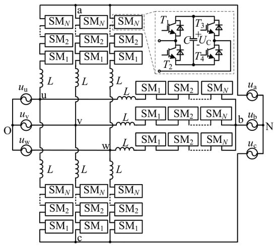
As illustrated in Figure 2, the M3C topology consists of nine arms, where each arm is composed of an inductor L series with N cascaded sub-modules (SM). The three-phase AC systems on both sides of M3C are interconnected by these nine arms. The sub-modules of the M3C generally adopt a full-bridge configuration, consisting of one capacitor and four switching devices. By controlling the on-off state of the switches, each sub-module can operate in three modes: positive insertion, negative insertion, and bypass. By combining the operating states of all SMs in each arm, the actual arm voltage can be regulated to closely track its reference value, thereby controlling the currents on both the low-frequency and power-frequency sides of the M3C.
Figure 2.
Topology of M3C.
2.2. Control Strategy of M3C
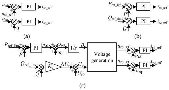
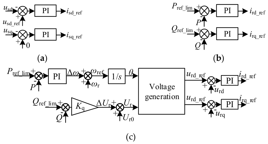
In LFAC systems, the low-frequency side of the M3C is responsible for establishing the voltage for the offshore wind farm, while the power-frequency side facilitates the power injection into the grid. Therefore, the low-frequency side of the M3C employs constant AC voltage control, while the power-frequency side can operate under either grid-following or grid-forming control strategies. The voltage outer loop for the low-frequency side, the grid-following power outer loop for the power-frequency side, and the grid-forming power outer loop for the power-frequency side are illustrated in Figure 3a, Figure 3b and Figure 3c, respectively. Here, usd and usq represent the voltages in the low-frequency side under synchronous rotating reference frame, and usd_ref denotes the reference value for the d-axis voltage on the low-frequency side.
Figure 3.
Outer loop control of M3C: (a) Voltage outer loop on low-frequency side; (b) Grid-following power outer loop on power-frequency side; (c) Grid-forming power outer loop on power-frequency side.
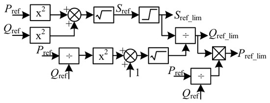
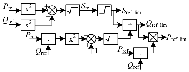
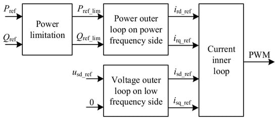
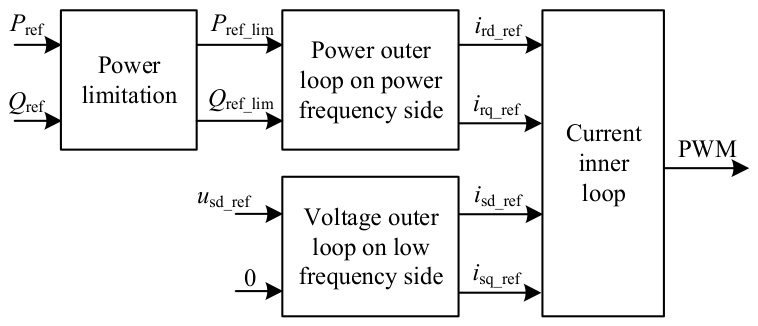
Due to the constraints of device stress on the power output capability of M3C, the power reference values must be limited; the resulting limited power references are denoted as Pref_lim and Qref_lim. When the apparent power reference Sref exceeds the limit Sref_lim, the power references are constrained based on the ratio of the current active and reactive power references, as illustrated in the power limiting strategy in Figure 4. Therefore, the overall control block diagram of the M3C is presented in Figure 5.
Figure 4.
Power limitation control of M3C.
Figure 5.
Overall control block diagram of M3C.
During grid frequency disturbance, the M3C under grid-following control fails to provide frequency support. Grid-forming control emulates the grid-connection operating mechanism of synchronous generators. It adjusts the active power according to the phase angle difference between the output voltage and grid voltage, and it can actively provide inertial support for the grid. However, the frequency support capability of the M3C is constrained by the energy storage capacity of its sub-module capacitors and the design of its control strategy, resulting in limited inertial support.
During grid voltage disturbance, the M3C under grid-following control can adjust its reactive power by regulating the current at the point of common coupling (PCC) so as to provide voltage support for the onshore power-frequency grid. Under grid-forming control, voltage support can be naturally realized through reactive power-voltage droop characteristics. However, regardless of the control, the voltage support capability of the M3C is constrained by its capacity and transient overcurrent capability, and it also relies on the rational design of the control strategy and its parameter configuration.
3. LFAC Transmission System of Offshore Wind Power Based on M-G
3.1. Operation Principles of M-G
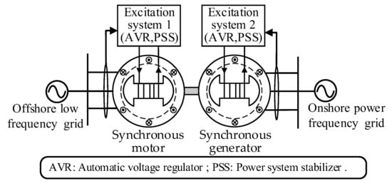
The structure of the M-G is illustrated in Figure 6. The rotors of the synchronous motor and synchronous generator are coaxially connected, with the stator terminals of the synchronous motor linked to the offshore low-frequency grid and those of the synchronous generator connected to the onshore power-frequency grid.
Figure 6.
Structure of M-G.
Unlike power electronic-based frequency conversion technology, the M-G achieves frequency transformation by presetting the ratio of pole-pair numbers between the motor and the generator. The relationship between the frequency and the number of pole pairs for the synchronous motor and the synchronous generator can be expressed as:
where fonshore, nG, and pG represent the onshore grid frequency, the mechanical speed, and the number of pole pairs of the synchronous generator, respectively; foffshore, nM, and pM denote the offshore grid frequency, the mechanical speed, and the number of pole pairs of the synchronous motor, respectively.
Since the rotors of the synchronous motor and the synchronous generator are coaxially connected, i.e., nM = nG, substituting this into Equation (1) yields:
Consequently, the LFAC power from the offshore wind farm is fed into the stator windings of the synchronous motor, where the stator generates a rotating magnetic field to drive the rotor at a corresponding speed, thereby converting electrical energy into mechanical energy. The mechanical torque generated by the motor is transmitted via the shaft system to the generator rotor, driving its rotation. Under the regulation of the excitation system, the synchronous generator induces power-frequency AC power compliant with grid standards at its stator terminals, effectively converting mechanical energy into electrical energy. This entire process leverages the physical coupling characteristics between the rotating machines to achieve electromagnetic isolation and frequency conversion from the low-frequency system to the power-frequency system through the electrical–mechanical–electrical energy conversion chain.
3.2. Mathematical Modeling of M-G
In the M-G, there is no electrical connection between the stator windings of the motor and the generator; consequently, their electromagnetic variables, such as flux linkages, voltages, and currents, are decoupled [23], which signifies inherent electromagnetic isolation. Meanwhile, the rotors of the motor and generator are linked via a common shaft, establishing a significant coupling relationship between their rotational speeds, which represents mechanical coupling.
The mathematical model of the M-G is described by flux linkage equations, voltage equations, and rotor motion equations [24]. Considering the inherent electromagnetic isolation and mechanical coupling characteristics of the M-G, this paper focuses on the analysis of the rotor motion equations.
The rotor motion equations for the motor and generator in the M-G can be expressed as:
where ωM and ωG are the mechanical angular speeds of the motor and the generator; HM and HG are the inertia time constants; TMe and TGe are the electromagnetic torques; TMm and TGm are the mechanical torques; DM and DG are the damping coefficients; ΔωM and ΔωG are the mechanical angular speed deviations of the motor and generator, respectively.
Assuming a rigid coupling between the motor and generator and neglecting the mechanical losses of the shaft system, i.e., ωM = ωG, TMm = TGm substituting these into Equation (3) yields the overall rotor motion equation for the M-G as:
where ωM-G is the mechanical angular speed of the M-G; HM-G is the inertia time constant, defined as HM-G = HM + HG; and DM-G is the damping coefficient, defined as DM-G = DM + DG.
3.3. Operating Characteristics of M-G
The operating characteristics of the M-G, referred to as power-angle characteristics, primarily comprise both active and reactive power-angle relations. Due to the mechanical shaft, which blocks reactive power exchange between the low-frequency and power-frequency grids, the reactive power-angle characteristics of the motor and the generator are relatively independent. Meanwhile, the mechanical shaft facilitates active power transmission from the low-frequency grid to the power-frequency grid, resulting in inherent coupling between the active power-angle characteristics of the motor and the generator. Consequently, this paper focuses on the analysis of the active power-angle characteristics of the M-G.
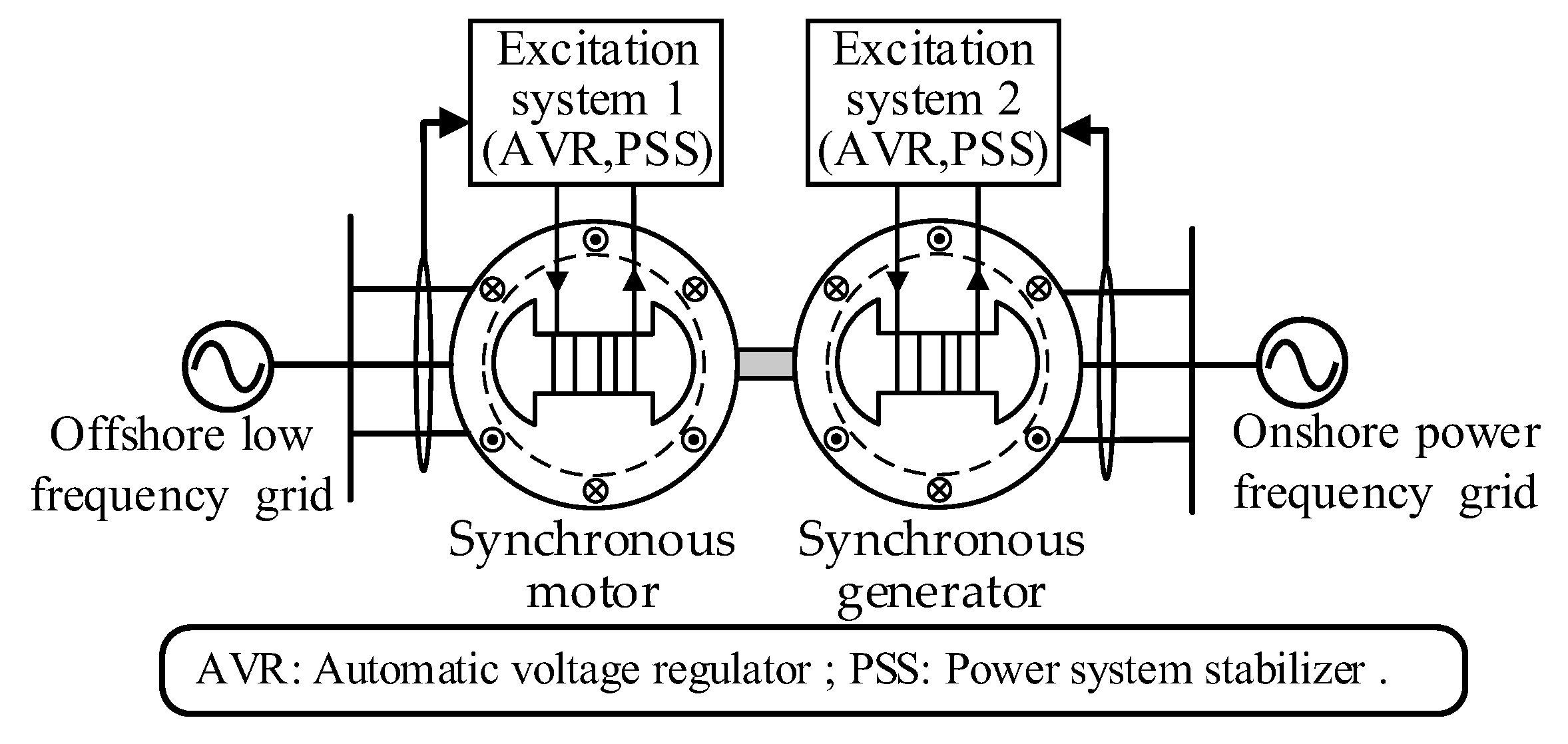
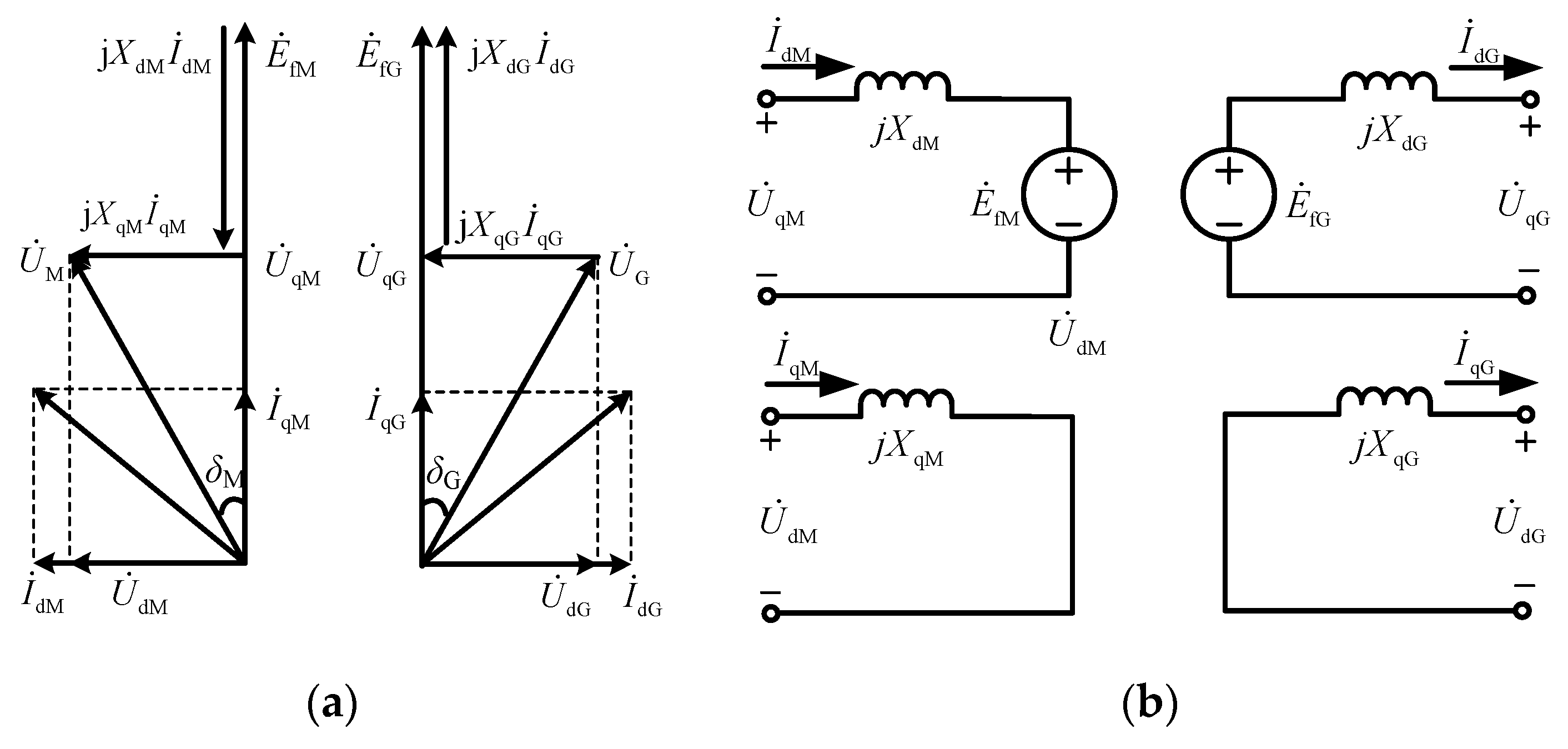
The phasor diagrams and equivalent circuits of the M-G are shown in Figure 7, and the corresponding active power-angle characteristic expression of the synchronous machines is given by:
where PM and PG are the electromagnetic power of the motor and the generator; EfM and UM are the excitation electromotive force (EMF) and terminal voltage of the motor, respectively; EfG and UG are the excitation EMF and terminal voltage of the generator, respectively; XdM and XdG are the d-axis reactance of the motor and generator; XqM and XqG are the q-axis reactance of the motor and generator; and δM and δG are the power angles of the motor and generator, respectively.
Figure 7.
Phasor diagrams and equivalent circuits: (a) Phasor diagrams; (b) Equivalent circuits.
Neglecting mechanical losses, i.e., |PM| = |PG|, and substituting this into Equation (5) yields:
As indicated by Equation (6), when EfM (EfG) and UM (UG) remain constant, the power angles of the motor δM and generator δG vary synchronously; the magnitudes of these power angles are determined by the active power transmitted from the offshore wind farm to the onshore grid.
4. Analysis and Assessment of Grid Support Capabilities Based on M-G
4.1. Analysis of the Frequency Support Capability of M-G
4.1.1. Analysis of the Frequency Support Mechanism
The frequency support provided by the M-G-based LFAC system consists of two parts: the inherent support from the M-G itself and the coordinated support from the offshore wind farm. In particular, the frequency support of M-G to the onshore power-frequency grid can be divided into two stages: the electromagnetic response stage and the inertial response stage.
During the electromagnetic response stage, the disturbance-induced active-power imbalance is distributed between the synchronous generator in the M-G and the onshore synchronous generator according to their respective synchronizing power coefficients. According to the definition of the synchronizing power coefficient [26], the synchronizing power coefficient of the M-G synchronous generator side KG, can be expressed as:
where P′G is the transient synchronizing power of the M-G synchronous generator; E′fG is the transient EMF; X′dG is the transient d-axis reactance.
During the inertial response stage, to compensate for the power imbalance caused by the sudden increase in electromagnetic power, the M-G, similar to onshore synchronous generators, spontaneously provides frequency support to the grid by decelerating its rotors and releasing stored kinetic energy.
As indicated by Equation (2), a decrease in rotor speed leads to a simultaneous decline in the frequency of the offshore low-frequency grid. In this case, if the offshore wind farm is equipped with virtual inertia control, the wind turbines can release their rotor kinetic energy to achieve a transient increase in active power output. The reference power for the wind turbines with supplementary virtual inertia control, PWT,ref is expressed as:
where PMPPT is the reference power under maximum power point tracking (MPPT) control; ΔPVI is the additional active-power reference provided by virtual inertia control; KVI is the virtual inertia coefficient; and fPLL is the frequency of the offshore grid measured by the phase-locked loop (PLL).
Consequently, the M-G-based LFAC system can not only provide frequency support to the onshore grid by leveraging the rotor inertial response of the M-G, but also further enhance the overall frequency support capability of the integrated system by designing frequency regulation control strategies for the offshore wind farm.
4.1.2. Quantitative Analysis of Frequency Support Capability
To quantify the inertial support capability of the M-G, an equivalent inertia characterization is required. Based on the definition of the inertia time constant in [27], it follows that:
where ΔEiner is the additional kinetic energy released by the M-G to provide inertial support following a frequency event; Δfpu is the per-unit (p.u.) value of the frequency deviation of the onshore synchronous generator; and SSG is the rated capacity of the onshore synchronous generator.
where JM-G is the physical inertia of the M-G; ωN is the rated mechanical angular speed of the M-G; ωiner is the mechanical angular speed of the M-G after inertia support.
When a frequency event occurs in the power grid, the M3C can also provide inertia support like the M-G. However, due to the absence of a mechanical shaft, all the energy for its inertia support is derived from its internal capacitor energy.
where Ceq is the equivalent capacitance of the M3C, UN is the rated capacitor voltage of the M3C, and Uiner is the capacitor voltage after inertia support.
4.2. Analysis of Voltage Support Capability of M-G
4.2.1. Analysis of Voltage Support Mechanisms
The voltage support provided by the M-G to the onshore grid encompasses an inherent fast response from the machine itself at the onset of a voltage sag [28], and followed by sustained voltage support facilitated by the excitation system through the modulation of the excitation EMF. Furthermore, owing to the electrical isolation between the synchronous motor and the synchronous generator within the M-G, their respective excitation systems independently perform voltage regulation for the offshore and onshore grids.
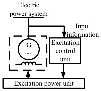
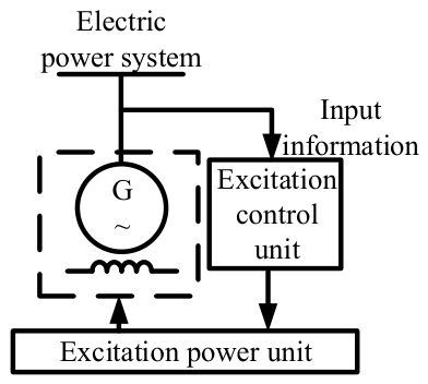
The excitation system comprises an excitation control unit and an excitation power unit, the overall architecture of which is illustrated in Figure 8. Specifically, the inputs to the excitation control unit include the terminal voltage reference UG,ref, the terminal voltage UG, the terminal current IG, and the output of the excitation power unit is the generator excitation EMF EfG.
Figure 8.
Excitation system of M-G.
During a sudden surge in reactive load on the onshore grid, and prior to the response of the excitation system, the system suffers from a deficit in reactive power sources, causing the grid to converge toward a reactive power balance at a reduced voltage level [29]. This leads to a decline in the bus voltages of the onshore grid. The relationship between the reactive power QG of the synchronous generator and the excitation EMF EfG within the M-G is formulated as:
As indicated by Equation (12), upon detecting a decrease in the terminal voltage UG, the excitation system of the synchronous generator within the M-G, augments the excitation EMF EfG to increase the reactive power of the generator. Consequently, the onshore grid can re-establish reactive power balance at a voltage level closer to the nominal voltage.
4.2.2. Quantitative Analysis of Voltage Support Capability
To quantify the reactive power support capability, assumptions are made based on the different overcurrent characteristics of the M-G and the M3C. The synchronous machines in the M-G are assumed to withstand up to 1.5 times the rated current for a short duration without damage, whereas the short-term current limit of the M3C is assumed to be 1.1 times the rated current.
Assuming a voltage of 1.0 p.u. at the PCC, the relationship between the per-unit maximum reactive power , maximum reactive current , maximum total current , and the current active current component is defined as follows:
When the M-G and M3C have the same rated capacity and both operate at 0.8 p.u. of rated active power, the short-term voltage support capability of the M3C is 0.754 p.u., while that of the M-G is 1.269 p.u., which is 68.3% higher than that of the M3C.
4.3. Analysis of the Fault-Isolation Capability of M-G
A previous study has demonstrated the fault-isolation function of the M-G in renewable energy generation systems through simulation and experimental results. Under grid voltage sag, overvoltage, and multiple voltage sag conditions, the M-G can isolate grid faults on the generator side, reduce the disturbance transmitted to the motor side, and provide voltage support to the grid during faults [23]. Due to the mature excitation control and transient regulation mechanism, the M-G can, to some extent, isolate the interactions between source-side and grid-side electrical faults through its mechanical shaft and electromagnetic isolation. This weakens the direct impact of power-frequency-side faults on the low-frequency-side grid and helps maintain the voltage and power stability of the offshore grid. Therefore, the M-G-based offshore wind power low-frequency grid-connection system generally exhibits stronger fault-isolation capability.
In contrast, when a fault occurs on the power-frequency side of the M3C, the low-frequency-side converter will continue to output power normally if no fault ride-through control strategy is configured. This may cause a power imbalance between the M3C and the offshore wind farm, leading to an overvoltage risk in the converter and threatening system safety.
In addition to the aforementioned key performances such as inertia support, short-term voltage support and fault isolation, there are also certain differences between the M3C and the M-G in terms of dynamic performance, service life and other aspects. The overall technical characteristics of the M3C and the M-G are compared in Table 1.
Table 1.
Comparison of technical characteristics between the M3C and M-G.
5. Simulation Verification of LFAC Transmission System Based on M-G
The simulation structure of the LFAC system is shown in Figure 9. The electric powerfrom the offshore wind farm passes through a step-up transformer, and is then transmitted to the frequency conversion device via submarine cable and a step-down transformer. The frequency conversion device, together with the synchronous generator representing the grid, provides power to the loads. The parameters of the LFAC system, M3C, and M-G are listed in Table 2, Table 3 and Table 4. The loads consist of a 25 MW fixed active load, a 2.5 MW switchable active load, a 3 MVar fixed reactive load, and a 10 MVar switchable reactive load. Taking the variation of active loads as an example, the frequency support capability of the M-G is analyzed.
Figure 9.
Schematic diagram of LFAC system in simulation.
Table 2.
Parameters of the LFAC transmission system.
Table 3.
Parameters of M3C.
Table 4.
Parameters of M-G.
5.1. Simulation Verification of Frequency Support Capability of M-G
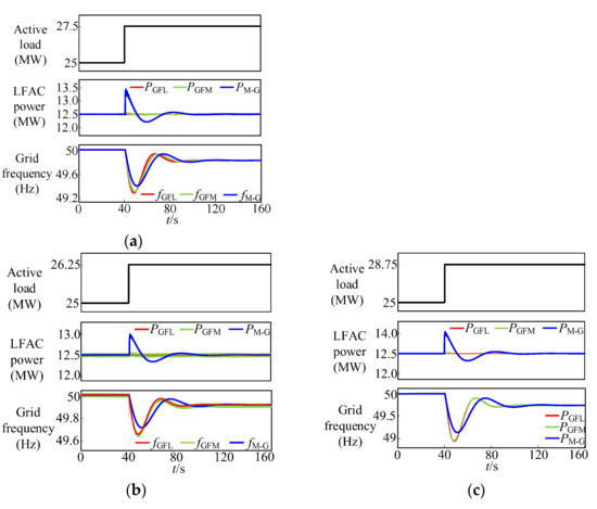
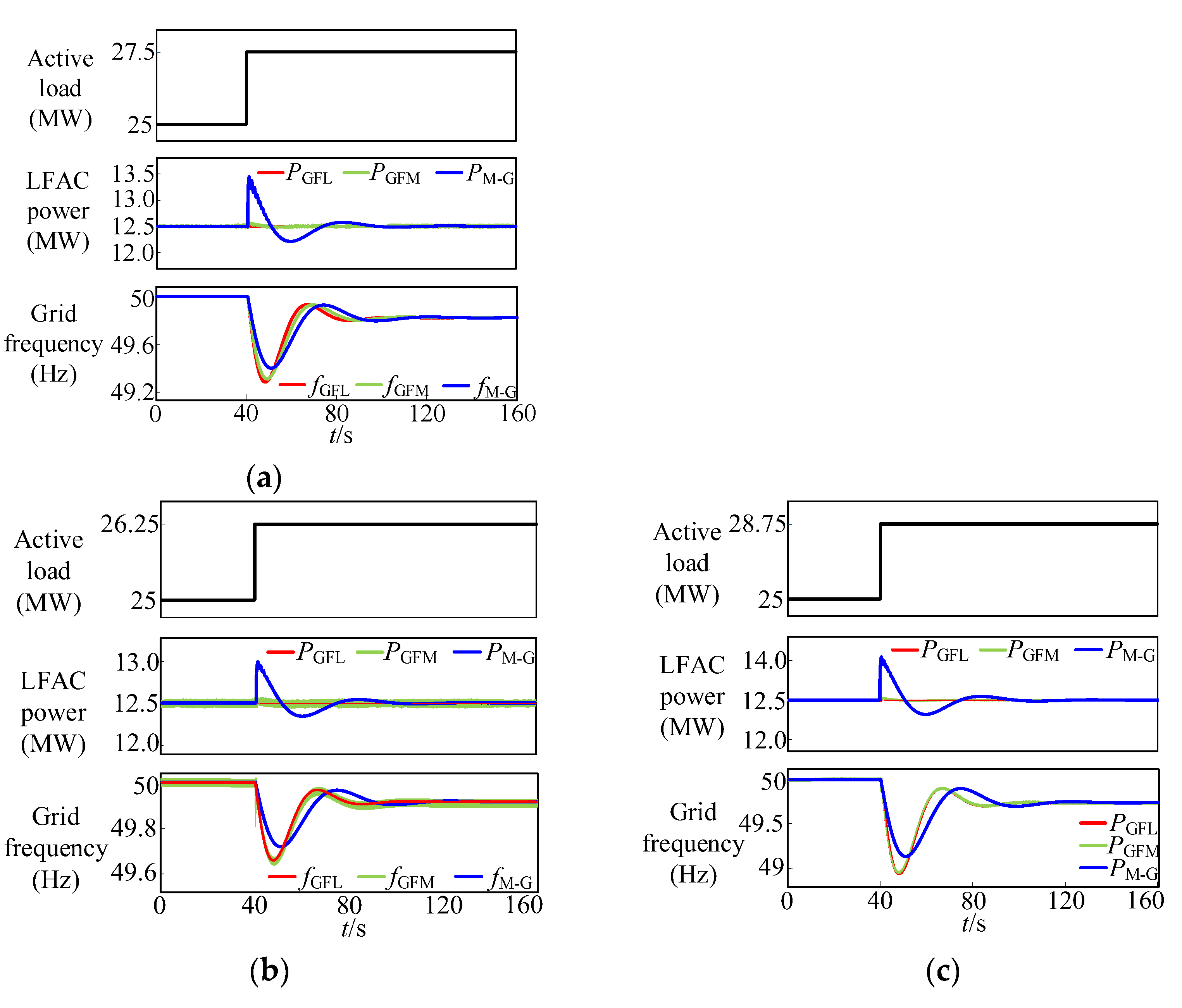
To study the frequency support capability of the M-G, the load was increased by 10% at 40 s; that is, the active load increased abruptly from 25 MW to 27.5 MW. Figure 10a shows the variation curves of the total active load, the active power from the LFAC system, and the grid frequency when the offshore wind farm operates in MPPT mode.
Figure 10.
Frequency support waveforms of M-G and M3C under different load variations with constant wind farm output power: (a) Load increase by 10%; (b) Load increase by 5%; (c) Load increase by 15%.
A comparative analysis was conducted between the M3C and the M-G under the grid-following and grid-forming control strategies, respectively. When the load changes abruptly, the M3C with the traditional grid-following control strategy will not change the output current reference value with the change of grid frequency, so there is no obvious change in the output active power PGFL. Both the M3C under grid-forming control and the M-G can provide inertia support, so they will naturally increase active power output when the load increases abruptly. However, since the M3C lacks real mechanical inertia support, its instantaneous increased power in PGFM is still smaller than that in PM-G. Since the active power from the offshore wind farm remains unchanged, the energy released during the inertia support process mainly comes from the energy stored in M3C capacitors or the M-G rotor kinetic energy. Limited by the inability of the capacitor energy storage and rotor kinetic energy to be continuously released, the system is difficult to provide long-term frequency support. Therefore, the output active power drops after a short-term increase and stabilizes at 12.5 MW after 100 s.
Since the droop coefficient of the onshore gird synchronous generator is consistent in the three groups of simulations, and the offshore wind farm does not participate in primary frequency regulation, the grid frequency in both groups of simulations returns to 49.81 Hz after dropping. However, during the frequency-drop process, according to the calculation method in Section 4.1.2, the inertia time constant of the M-G is 6.92 s, and the lowest frequency point is 49.40 Hz. In contrast, due to the limited capacitor energy storage of the M3C, its inertia time constant is 0.49 s, and the lowest frequency point drops to 49.31 Hz. The simulation results show that inertia support effectively alleviates the onshore grid frequency drop. The M-G has stronger support capability because it has natural physical inertia and can store more energy.
To verify whether the above conclusions remain valid under different load variations, the control strategy is kept unchanged, and the load is varied by 5% and 15%. The simulation results are presented in Figure 10b,c, which shows that the frequency drop becomes more severe as the load increment grows. Nevertheless, the M-G system still exhibits a stronger frequency support capability than the M3C converter.
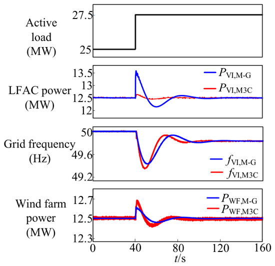
To further enhance the inertia support capability of the LFAC system, the offshore wind farm can adopt virtual inertia control, adjusting the active power output according to the frequency change rate of the low-frequency side. When the grid frequency changes, the mechanical rotating shaft of the M-G naturally has the ability to transmit the frequency change to the low-frequency side. In contrast, the M3C can proportionally map the grid frequency to the low-frequency side through control strategies, thereby obtaining a structure similar to the M-G virtual inertia control.
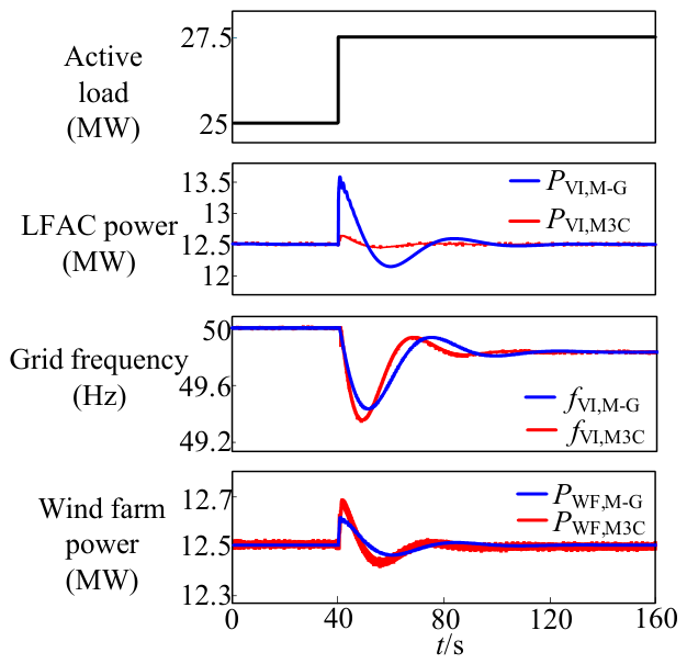
Figure 11 shows the waveforms of the active load, LFAC power, grid frequency, and wind farm power under virtual inertia control. It is found that compared with the case without virtual inertia control, the frequency response fVI,M-G of the M-G under virtual inertia control has the lowest frequency point raised from 49.40 Hz to 49.42 Hz. After the M3C adopts virtual inertia control, although the wind farm output power PWF,M3 is greater than PWF,M-G when the load increases abruptly, the frequency drop is still significantly larger than that of the M-G because the energy that can be released by the capacitor is much less than that of the real mechanical rotating shaft.
Figure 11.
Waveforms of frequency support of the M-G and M3C under virtual inertia control.
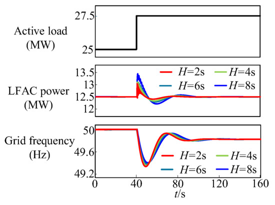
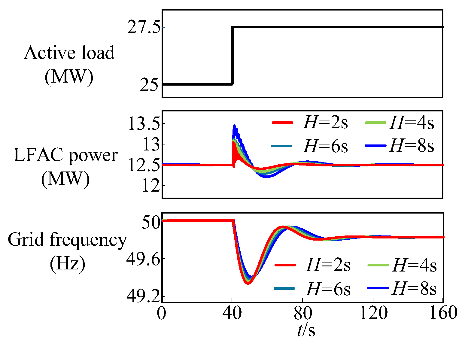
To compare the differences in the frequency support capability of the M-G under different inertia time constants, the wind farm operated in MPPT mode, other parameters were kept unchanged, the inertia time constant was adjusted from 2 s to 8 s, and the grid frequency drop was observed. The comparison of the frequency support of the M-G under different inertia time constants is shown in Figure 12. The simulation results show that with the increase of the inertia time constant, the active power increased by the M-G during the abrupt increase of grid load increases, thereby suppressing the grid-frequency drop.
Figure 12.
Waveforms of frequency support of the M-G under different inertia time constants.
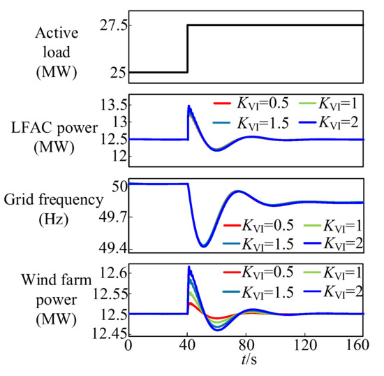
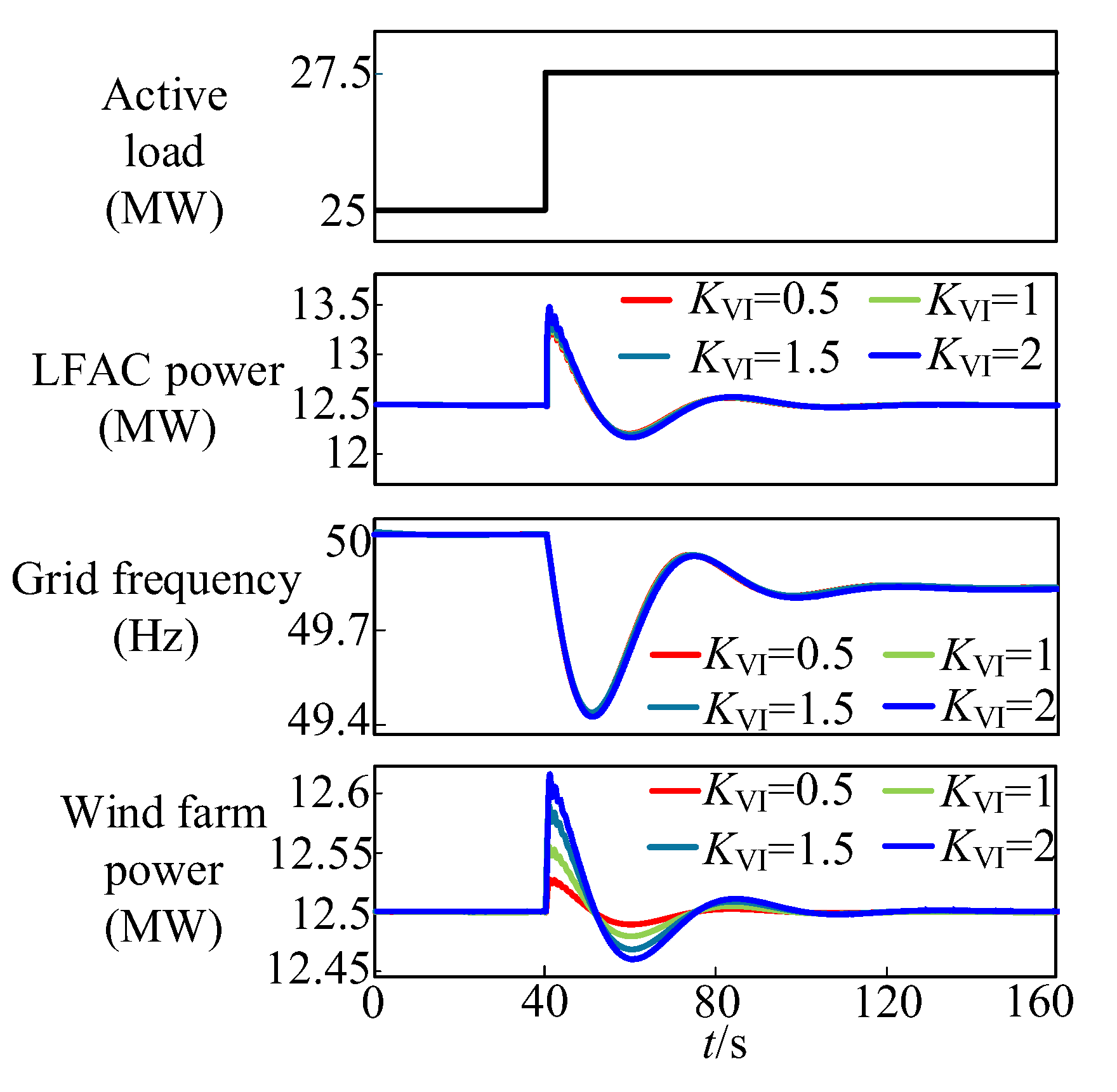
To compare the influence of wind farm-side virtual inertia control on the frequency support performance of the M-G, the virtual inertia coefficient is varied from 0.5 to 2, and the corresponding simulation curves are presented in Figure 13. The simulation results reveal that as the virtual inertia coefficient increases, the instantaneous additional active power output of the wind farm grows gradually under sudden load increase, while its suppression effect on grid frequency drop is relatively limited. This indicates that the system inertia support mainly relies on the inherent inertia response of the M-G.
Figure 13.
Waveforms of frequency support under different virtual inertia coefficients.
5.2. Simulation Verification of Voltage Support Capability of M-G
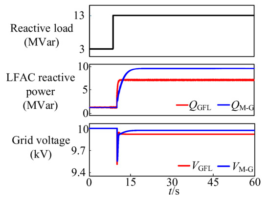
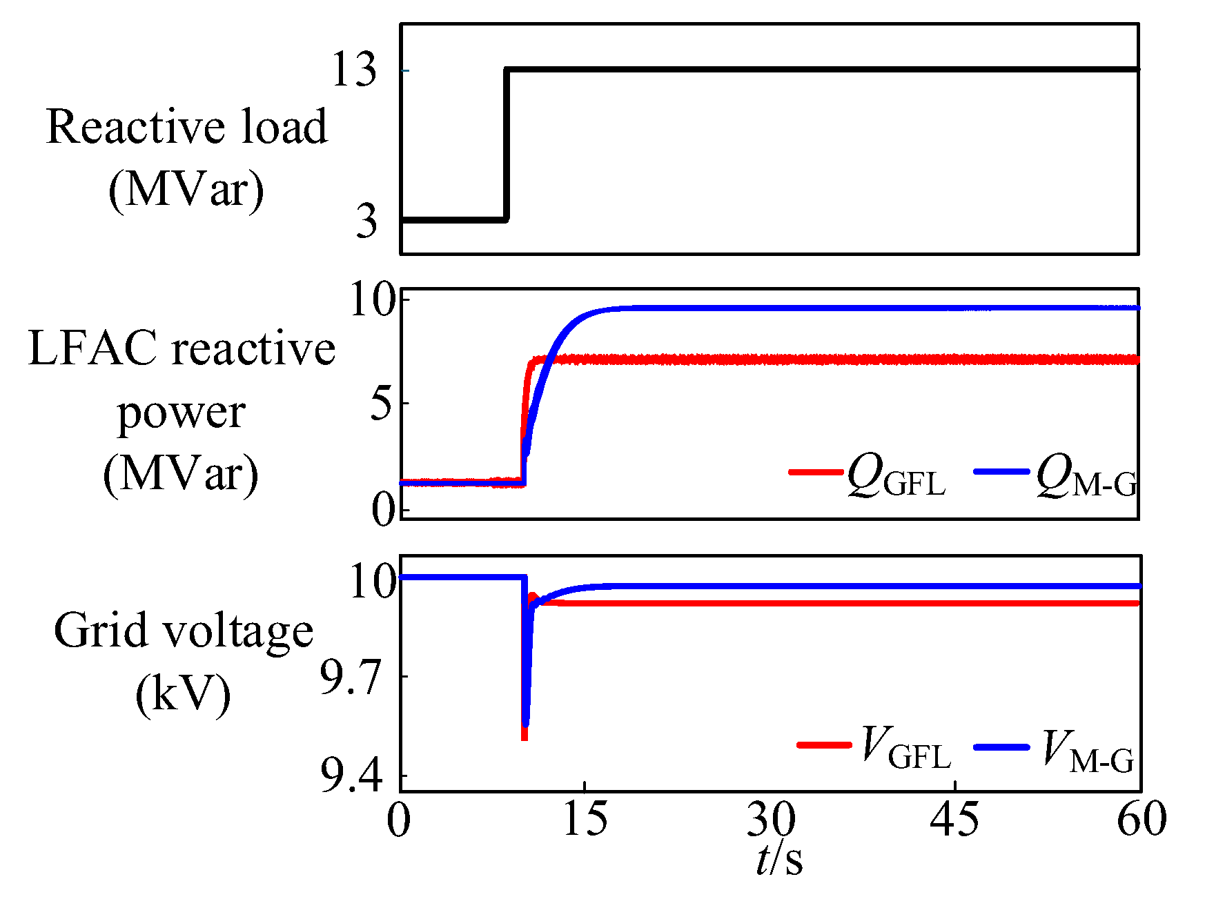
To compare the difference in voltage support capabilities between the two frequency-conversion devices, the reactive load was suddenly increased by 10 MVar at 10 s. The M-G increases its reactive power through its excitation system, while the M3C adjusts the reactive power reference value through a proportional link according to the degree of grid voltage drop. Figure 14 shows the variation curves of the total reactive load of the LFAC system, the reactive power by the frequency conversion device, and the grid voltage. It can be seen from the comparison that after the sudden increase in reactive load, the M3C has a faster reactive power increase rate and stabilizes at 6.95 MVar of reactive power output. However, its output capacity is limited by the rated current, and the maximum reactive power output cannot meet the system demand. In contrast, although the M-G has a slower reactive power increase rate, it has strong overcurrent capacity. After about 8 s of the load sudden change, the stable reactive power output can reach 9.6 MVar, which is significantly higher than that of the M3C. The difference in the short-term reactive power output of the two devices leads to different degrees of grid voltage drop. The effective value of the line voltage of the M3C drops to 9.92 kV, while the line voltage of the M-G only drops to 9.96 kV. The simulation results show that the M3C can provide faster voltage support, but its output capacity is limited; the M-G has slower response speed but stronger short-term voltage support capacity, which can better suppress the grid voltage drop and maintain the stability of the power system.
Figure 14.
Waveforms of voltage support of M3C and M-G.
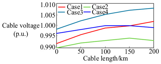
To analyze the impact of the amplification coefficient KA of the excitation system on the motor side of the M-G on the voltage distribution along the submarine cable, four simulation working conditions were designed, considering the differences in HVR configuration methods. Specifically, KA = 50 for Case 1 and Case 2, and KA = 100 for Case 3 and Case 4; a 54 MVar HVR was only configured on the shore-side of the submarine cable in Case 1 and Case 3, while a 27 MVar HVR was configured at both ends of the cable in Case 2 and Case 4. The voltage distribution along the submarine cable under these four conditions is shown in Figure 15. By comparing Case 1 and Case 3, it is found that increasing KA can lift the voltage on the motor side. Since the HVR is only installed on the shore side, the capacitive charging reactive power of the cable accumulates gradually with the increase of cable length, leading to an overall upward trend of the voltage along the line. In contrast, comparing Case 2 and Case 4, it is clear that configuring HVRs at both ends of the cable can effectively suppress the overall upward trend of the voltage along the submarine cable. Among all working conditions, the voltage along the cable in Case 4 is the closest to the rated value. This proves that in the M-G system, appropriately increasing KA of the excitation system on the motor side and reasonably arranging HVRs at both ends of the submarine cable can achieve coordinated cooperation between the excitation system and HVR reactive power compensation. This coordination can effectively improve the voltage distribution along the submarine cable and keep it around 1.0 p.u.
Figure 15.
Voltage distribution along the submarine cable under different excitation-system gains and shunt reactor configurations.
5.3. Simulation Verification of Fault-Isolation Capability of M-G
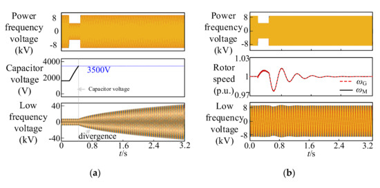
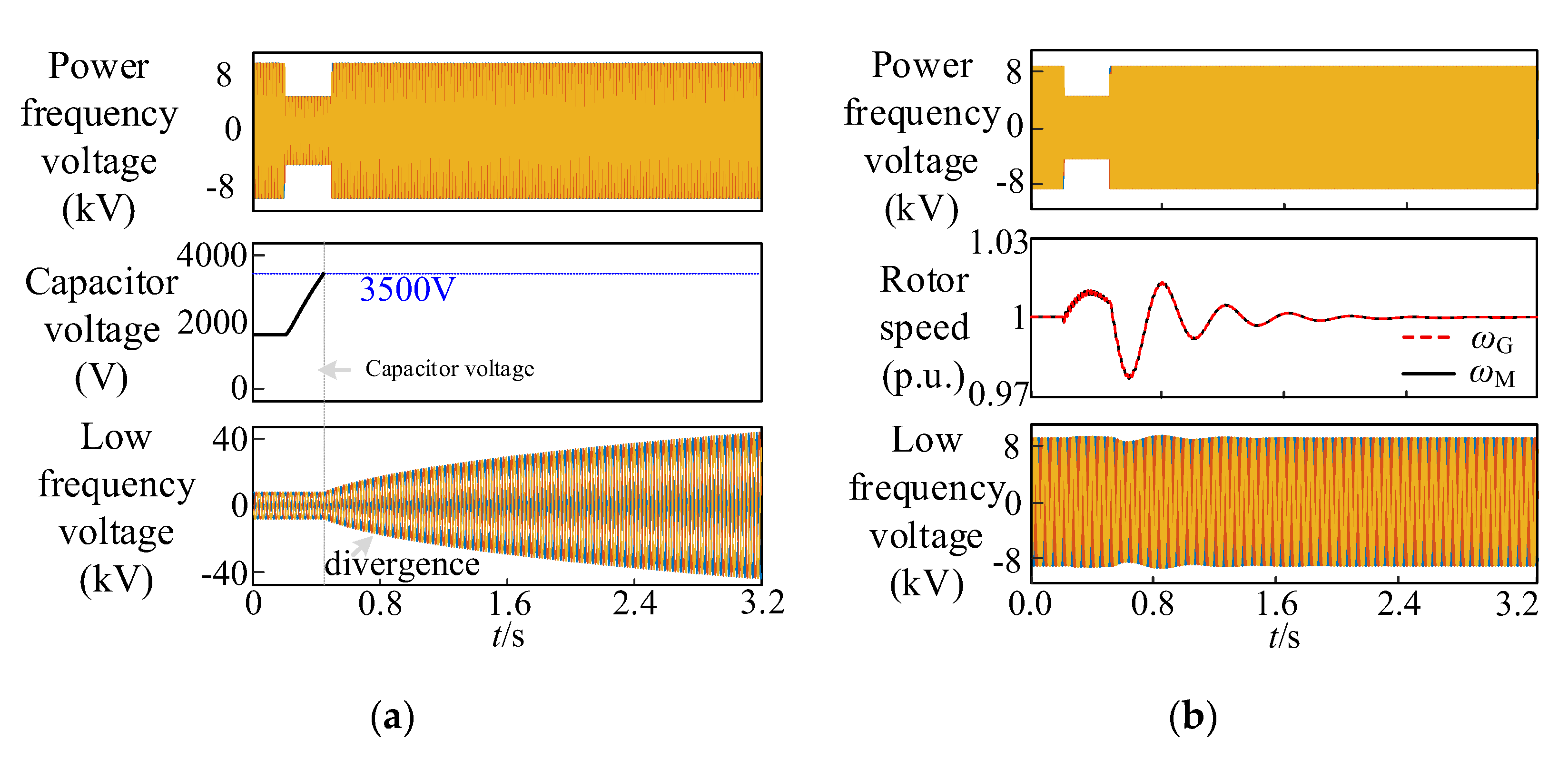
To compare the performance of M3C and M-G under fault conditions, a three-phase voltage sag fault is adopted as the test case. The grid voltage drops from 10 kV to 5 kV and recovers after a duration of 300 ms. The operating states of M3C and M-G are investigated accordingly. The relevant waveforms during the fault are presented in Figure 16.
Figure 16.
Waveforms of M-G and M3C under three-phase voltage sag: (a) Waveforms of M3C; (b) Waveforms of M-G.
It can be seen that when a fault occurs, the current limiting of the M3C restricts its ability to deliver active power to the grid. Meanwhile, the offshore wind farm operates under constant power control, causing the capacitor voltage to rise rapidly. Once the voltage reaches the limit, the submodules are blocked to protect the converter from damage, causing the M3C to lose its ability to establish the low-frequency-side voltage. The resulting instability of the offshore grid may disturb the normal operation of the offshore wind turbine converters and, in severe cases, threaten their safe operation or damage the converter hardware.
Furthermore, as shown in Figure 16b, during the power-frequency-side voltage sag, the voltage on the power-frequency side decreases significantly, whereas the low-frequency-side voltage only exhibits limited fluctuations. This indicates that the disturbance caused by the power-frequency-side fault is not directly transferred to the offshore low-frequency grid. As a result, the impact on the offshore grid voltage is effectively weakened, and the operating condition of the offshore wind farm is less affected. Therefore, the simulation results further verify that the M-G scheme can suppress the direct propagation of power-frequency-side faults to the low-frequency side and exhibits better fault-isolation capability.
5.4. Simulation Verification of Weak-Grid Operation Capability of M-G
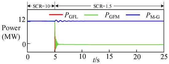
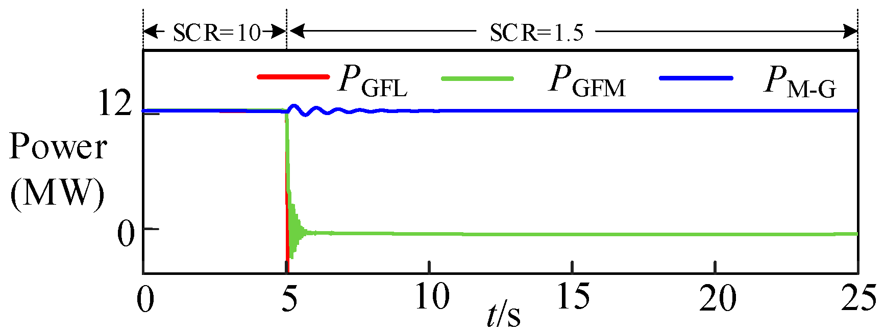
To compare the performance between the M3C and M-G under weak grid conditions, the short-circuit ratio (SCR) is stepped down from 10 to 1.5 at 5 s. The corresponding results are shown in Figure 17. It is demonstrated that both grid-following and grid-forming M3Cs are highly sensitive to control parameters and tend to become unstable when the grid short-circuit ratio is low. In contrast, the M-G adopts synchronous machines for grid connection and therefore exhibits much better stability.
Figure 17.
Active power waveforms of M3C and M-G when the short-circuit ratio changes from 10 to 1.5.
6. Conclusions
This paper focuses on the application of the M-G in LFAC system of offshore wind power. It presents the basic principle and mathematical model of the M-G, analyzes its capabilities in frequency support, voltage support, and fault isolation, and conducts simulation verification. The results show that:
In terms of frequency support, due to its real physical inertia, the M-G can provide strong frequency support when the active load of the onshore power grid suddenly increases. Increasing the inertia time constant of the M-G can further improve the lowest frequency point.
In terms of voltage support, the M-G has strong short-term overcurrent ability and large reactive power output margin, which can effectively suppress the voltage drop of the onshore power grid when the reactive load suddenly increases. In addition, the simulation results of the voltage along the submarine cable show that reasonably configuring the high-voltage reactor at both ends of the submarine cable and appropriately increasing the amplification factor of the excitation system on the motor side of the M-G can improve the voltage distribution along the submarine cable, keeping the cable voltage close to the rated value.
In summary, the M-G low-frequency grid-connected system has strong capabilities in frequency support, voltage support, and low-frequency side voltage regulation, which can effectively maintain the stable operation of the power system and meet the operation requirements of the offshore wind power transmission system.
Author Contributions
Conceptualization, X.Z. and Q.L.; methodology, X.Z. and Q.L.; software, X.Z., T.X. and H.Y.; validation, B.Y. and X.Z.; formal analysis, B.Y. and X.Z.; investigation, B.Y.; resources, B.Y.; data curation, T.X. and H.Y.; writing—original draft preparation, T.X. and H.Y.; writing—review and editing, L.G.; visualization, T.X. and H.Y.; supervision, X.Z.; project administration, L.G.; funding acquisition, Q.L., X.Z. and L.G. All authors have read and agreed to the published version of the manuscript.
Funding
This research was funded by the project of State Grid Jiangsu Electric Power Co., Ltd.: Research on Operation Mechanism and Active Support Technology of Low-Frequency Grid Connection System for Offshore Wind Power with High-Inertia Supporting Capability Based on Motor-Generator Pair, grant number J2025116.
Data Availability Statement
The original contributions presented in this study are included in the article. Further inquiries can be directed to the corresponding authors.
Conflicts of Interest
Authors Xiaoming Zou and Qiang Li were employed by State Grid Jiangsu Electric Power Co., Ltd. Research Institute. The remaining authors declare that the research was conducted in the absence of any commercial or financial relationships that could be construed as a potential conflict of interest.
Abbreviations
The following abbreviations are used in this manuscript:
| VSC-HVDC | Voltage Source Converter-High Voltage Direct Current |
| LFAC | Low-Frequency Alternating Current |
| M3C | Modular Multilevel Matrix Converter |
| M-G | Motor-Generator Pair |
| HVR | High Voltage Reactor |
| SM | Submodules |
| PCC | Point of Common Coupling |
| EMF | Electromotive Force |
| MPPT | Maximum Power Point Tracking |
| PLL | Phase-Locked Loop |
References
- Qazi, S.H.; Bozalokov, D.; Vandevelde, L. Sustainable Offshore Power: Integrating BESS for a Greener Future. In Proceedings of the 2025 IEEE Green Technologies Conference (GreenTech), Wichita, KS, USA, 26–28 March 2025; pp. 103–107. [Google Scholar]
- Ma, X.; Wang, D.; Zhao, Z.; Lu, C.; Wang, C.; Liu, B. Preliminary Exploration on the Integrated Development of Offshore Wind Power Industry. In Proceedings of the 2025 International Conference on Smart Grid and Sustainable Energy (SGSE), Zhangye, China, 25–27 July 2025; pp. 1–6. [Google Scholar]
- Chen, X.; Li, L.; Liu, X.; Guo, Y.; Zhang, B.; Yang, L. Wind Turbine Performance Analysis of An Offshore Wind Farm in China. In Proceedings of the 2021 International Conference on Big Data and Intelligent Decision Making (BDIDM), Guilin, China, 23–25 July 2021; pp. 150–159. [Google Scholar]
- Fu, Y.; Liu, Z.; Zhao, L.; Tian, X.; Yuan, Z.; Yang, B. Offshore Wind Power Development and Transmission Technology Research in Shandong. In Proceedings of the 2022 IEEE/IAS Industrial and Commercial Power System Asia (I&CPS Asia), Shanghai, China, 8–11 July 2022; pp. 195–199. [Google Scholar]
- Zhang, P.; Zhao, B.; Gan, R.; Li, J.; Wang, X.; Xu, E. Offshore-Onshore Grid Synergistic Planning for Offshore Wind Power Bases Considering HVAC, LFAC and HVDC Transmission. In Proceedings of the 2025 7th Asia Energy and Electrical Engineering Symposium (AEEES), Chengdu, China, 28–31 March 2025; pp. 394–399. [Google Scholar]
- An, B.-H.; Lee, S.-Y.; Oh, J.-S.; Im, S.-W.; Kim, M.-J.; Park, T.-S. A Study on Deriving the Economic Critical Distance of LFAC Systems for Offshore Wind Power System. In Proceedings of the 2025 15th International Conference on Power, Energy, and Electrical Engineering (CPEEE), Fukuoka, Japan, 15–17 February 2025; pp. 444–449. [Google Scholar]
- Xiang, X.; Fan, S.; Gu, Y.; Ming, W.; Wu, J. Comparison of Cost-Effective Distances for LFAC with HVAC and HVDC in Their Connections for Offshore and Remote Onshore Wind Energy. CSEE J. Power Energy Syst. 2021, 7, 954–975. [Google Scholar] [CrossRef] [Scilit]
- Lu, Y.; Chen, A.; Guo, L.; Zhao, X.; Wang, X.; Xiang, N.; Dai, J. Low Frequency AC transmission for Offshore Wind Power. In Proceedings of the 2024 27th International Conference on Electrical Machines and Systems (ICEMS), Fukuoka, Japan, 26–29 November 2024; pp. 3750–3756. [Google Scholar]
- Zhang, Z.; Jin, Y.; Xu, Z. Modeling and Control of Modular Multilevel Matrix Converter for Low-Frequency AC Transmission. Energies 2023, 16, 3474. [Google Scholar] [CrossRef] [Scilit]
- Yuan, C.; Zhou, R.; Tong, M. Topologies and Control of Low-Frequency Alternating Current for Offshore Wind Farms Based on Modular Multilevel Matrix Converter. J. Eng. 2019, 16, 2271–2277. [Google Scholar] [CrossRef] [Scilit]
- Diaz, M.; Cardenas, R.; Ibaceta, E.; Mora, A.; Urrutia, M.; Espinoza, M.; Rojas, F.; Wheeler, P. An Overview of Applications of the Modular Multilevel Matrix Converter. Energies 2020, 13, 5546. [Google Scholar] [CrossRef] [Scilit]
- Diaz, M.; Cardenas, R.; Ibaceta, E.; Mora, A.; Urrutia, M.; Espinoza, M.; Rojas, F.; Wheeler, P. An Overview of Modelling Techniques and Control Strategies for Modular Multilevel Matrix Converters. Energies 2020, 13, 4678. [Google Scholar] [CrossRef] [Scilit]
- Fan, B.; Wang, K.; Wheeler, P.; Gu, C.; Li, Y. An Optimal Full Frequency Control Strategy for the Modular Multilevel Matrix Converter Based on Predictive Control. IEEE Trans. Power Electron. 2018, 33, 6608–6621. [Google Scholar] [CrossRef] [Scilit]
- Ma, J.; Liu, J.; Li, R.; Wang, C.; Hua, W.; Sun, Q. Inertia Support Method for LFAC Enabled by Optimized Energy Utilization of Dual-Port Grid-Forming Modular Multilevel Matrix Converters. Electronics 2025, 14, 4173. [Google Scholar] [CrossRef] [Scilit]
- Li, Y.; Wu, Q.; Jiang, Y.; Chen, J.; Zhou, Q. Coordinated Inertial Response Control Strategy for Modular Multilevel Matrix Converter and Low Frequency Offshore Wind Farm. IEEE Trans. Ind. Appl. 2025, 61, 7967–7976. [Google Scholar] [CrossRef] [Scilit]
- Han, H.; Ning, L.; Li, C.; Ye, Z.; Yang, C. Virtual Synchronous Generator Control Strategy of M3C Converter in Fractional Frequency Offshore Wind Power System. Electr. Power Eng. Technol. 2024, 43, 78–87. [Google Scholar]
- Wei, S.; Zhou, Y.; Xu, G.; Huang, Y. Motor–Generator Pair: A Novel Solution to Provide Inertia and Damping for Power System with High Penetration of Renewable Energy. IET Gener. Transm. Distrib. 2017, 11, 1839–1847. [Google Scholar] [CrossRef] [Scilit]
- Wei, S.; Zhou, Y.; Li, S.; Huang, Y. A Possible Configuration with Motor–Generator Pair for Renewable Energy Integration. CSEE J. Power Energy Syst. 2017, 3, 93–100. [Google Scholar] [CrossRef] [Scilit]
- Zhou, Y.; Xu, G.; Wei, S.; Zhang, X.; Huang, Y. Experiment Study on the Control Method of Motor–Generator Pair System. IEEE Access 2018, 6, 925–936. [Google Scholar] [CrossRef] [Scilit]
- Wei, S.; Zhou, Y.; Huang, Y. Synchronous Motor–Generator Pair to Enhance Small Signal and Transient Stability of Power System with High Penetration of Renewable Energy. IEEE Access 2017, 5, 11505–11512. [Google Scholar] [CrossRef] [Scilit]
- Wu, Q.; Huang, Y.; Li, C.; Gu, Y.; Zhao, H.; Zhan, Y. Small Signal Stability of Synchronous Motor–Generator Pair for Power System with High Penetration of Renewable Energy. IEEE Access 2019, 7, 166964–166974. [Google Scholar] [CrossRef] [Scilit]
- Gu, Y.; Huang, Y.; Li, C.; Guan, F.; Fu, W.; Zhan, Y.; Zhao, H. Effects of Motor–Generator Pair System on Improving Inertial Response and Primary Frequency Regulation Capability of Renewable Energy. IET Renew. Power Gener. 2021, 15, 313–325. [Google Scholar] [CrossRef] [Scilit]
- Gu, Y.; Huang, Y.; Wu, Q.; Li, C.; Zhao, H.; Zhan, Y. Isolation and Protection of the Motor–Generator Pair System for Fault Ride-Through of Renewable Energy Generation Systems. IEEE Access 2020, 8, 13251–13258. [Google Scholar] [CrossRef] [Scilit]
- Zhou, Y.; Huang, Y.; Gu, Y.; Li, C. Control of Motor–Generator Pair for Photovoltaic Power Grid Integration. CSEE J. Power Energy Syst. 2024, 10, 2341–2349. [Google Scholar]
- Li, C.; Huang, Y.; Deng, H.; Zhang, X.; Zhao, H. A Novel Grid-Forming Technology for Transient Stability Enhancement of Power System with High Penetration of Renewable Energy. Int. J. Electr. Power Energy Syst. 2022, 143, 108402. [Google Scholar] [CrossRef] [Scilit]
- Kundur, P.; Balu, N.J.; Lauby, M.G. Power System Stability and Control; McGraw-Hill: New York, NY, USA, 1994. [Google Scholar]
- Kosmecki, M.; Rink, R.; Wakszyńska, A.; Ciavarella, R.; Di Somma, M.; Papadimitriou, C.N.; Efthymiou, V.; Graditi, G. A Methodology for Provision of Frequency Stability in Operation Planning of Low Inertia Power Systems. Energies 2021, 14, 737. [Google Scholar] [CrossRef] [Scilit]
- Collins, E.R.; Jiang, J. Voltage Sags and the Response of a Synchronous Distributed Generator: A Case Study. IEEE Trans. Power Deliv. 2008, 23, 442–448. [Google Scholar] [CrossRef] [Scilit]
- Taylor, C.W. Power System Voltage Stability; McGraw-Hill: New York, NY, USA, 1994. [Google Scholar]



Disclaimer/Publisher’s Note: The statements, opinions and data contained in all publications are solely those of the individual author(s) and contributor(s) and not of MDPI and/or the editor(s). MDPI and/or the editor(s) disclaim responsibility for any injury to people or property resulting from any ideas, methods, instructions or products referred to in the content. |
© 2026 by the authors. Licensee MDPI, Basel, Switzerland. This article is an open access article distributed under the terms and conditions of the Creative Commons Attribution (CC BY) license.