


Abstract
A spatial system of cantilever bars is considered; the bars are fixed at one end and have the other end in common. The bars are straight ones. A given system of forces and torques acts on the bar system. The displacement of the common end is determined in the form of three linear displacements and three angular displacements. The calculation is carried out in screw coordinates. Various cases where certain components of the common end displacement have minimal values are also discussed. A numerical example is studied for different possibilities of the bar parameters. A particular case is that of a planar bar system. An extension of the problem is the case where, instead of the common end of the bars, the existence of a rigid body to which all the bars are connected is considered.
Keywords:
spatial systems of cantilever bars; small deformations; optimization; numerical calculation MSC:
37M99
1. Introduction
Many works consider various bar systems. Such a bar system is presented in reference [1], in which the bars have spherical joints at the ends and share a common end. The situation leads only to the existence of axial forces and, implicitly, longitudinal deformations.
A first case is that of mechanisms with elastic elements. Such a situation is described in [2], where the considered mechanical system has flexible elements. The connections are decoupled and simpler systems of equations are obtained. The method is applied to a four-bar mechanism. Another work [3] uses Lagrange’s equations to determine the motion. It is shown that difficulties arise when the mechanical system contains closed-loop topologies. The closed loops are converted into open systems using three methods. The theory is applied to a slider–crank mechanism. The comparison of different models of elastic elements is carried out in [4]. A new matrix approach is proposed, with validation being performed experimentally. Chen et al. [5] consider suspended parallel mechanisms and propose an algorithm based on inverse kinematics. The validation is carried out for a robot with two ropes (two-rope robot) and the experimental results are compared with the theoretical ones.
One paper [6] proposes an approach based on screw theory for a 6-3-type Gough–Stewart platform. The author carries out the analysis of positions, velocities, accelerations, and jerks. The manipulator based on the same Gough–Stewart platform is addressed in reference [7]. The fixed and mobile platforms have particular shapes. Screw theory is used, and a third-degree polynomial is obtained that defines the geometric locus of singularities. A new method called singularity–equivalent–mechanism is described, through which the analysis of singularities of the parallel manipulator is reduced to a simple positional analysis of an equivalent planar mechanism. Another work dedicated to Gough–Stewart platforms is [8]. It addresses the problem of the stiffness matrix in Cartesian coordinates for the case of a rotation-symmetric Stewart platform. The vibration study of a Stewart platform (three translations and three vibrations) actuated by legs and having the same natural frequency is carried out in paper [9]. Negative torsional stiffnesses are obtained. An optimization of the platform with an absorber is performed. The method is validated through numerical simulation. The case of asymmetric payload for a Stewart platform is discussed in paper [10] using the Lagrange approach. The solution obtained through inverse dynamics is validated both analytically using the Lagrange approach and numerically (ADAMS). The case of the direct problem and the inverse problem of the dynamics of a Stewart platform with external forces applied to the sides (rod) is addressed in reference [11]. It is shown that improving the accuracy of the platform’s motion simulation can be done in two ways, the most effective being a significant increase in the feedback factor.
Modeling of joint constraints for flexible multi-body systems is described in [12]. Each joint is considered to be composed of three basic primitives. In this way, a library of kinematic joints is created. Validation is performed numerically for the crank mechanism and slider mechanism, both having rigid and flexible elements. Another approach to flexible manipulators is presented in [13]. The approach is based on the first-order approximation of elastic displacements. Validation is carried out using a serial manipulator and a parallel manipulator.
The use of reciprocal screw theory for the kinetostatic analysis of parallel mechanisms that present particular cases of static indeterminacy and collinear forces is presented in work [14]. The method is applied to a 4-DOF 4-R (CRR) parallel manipulator, working with the help of screw theory.
Isolation of vibrations by using particular mechanisms (zero-stiffness suspension mechanisms) is discussed in [15]. The results are compared with those in the linear case, highlighting the superiority of the method.
The adaptation of a Stewart platform to different excitations is the subject of reference [16]. The control strategy proposed in the paper leads to very good results in the case of power reduction, control decoupling, and resistance to various excitations, even random ones.
Various bionic mechanisms are also proposed [17], with the study being carried out using the finite element method. The dynamic equations are obtained, and structural optimization solutions are highlighted.
Modeling a Stewart platform as a flexible multi-body system is presented in [18], which leads to easier derivation of the transfer equations. Validation is done numerically.
Vibration isolation for space payloads is addressed in work [19]. A Stewart platform is used and Lagrange’s equations are applied. The stability of the control system is tested, with the results being validated both theoretically and experimentally.
New mechanisms with flexible elements [20] are also being designed, with better performance under certain conditions.
The above shows that the main directions of study are: (i) related to mechanisms with flexible elements; (ii) the study of Gough–Stewart platforms with particular constructions; (iii) multi-body systems with flexible elements; (iv) vibration isolation; and (v) combining different approaches.
The ways of addressing the problems are based on the approach of classical mechanics equations (much more rarely and only in certain particular situations), Lagrange’s equations, equations specific to multi-body systems, or screw theory.
In general, the authors present study methods adapted to the problems addressed. The obtained equations are very complicated and nonlinear, leading to the small radius of convergence of the numerical methods used.
There is no general theory for the case of cantilever bar systems. Various particular cases of cantilever bars are presented in the literature [21].
In the most general case the system of bars may have rigid and elastic bars. In our study each bar is an elastic one. The presence of rigid bars is not considered for system of cantilever bars.
The case of cantilever bars is more complicated. In this situation the general deformation of a bar consists of a spatial bending and a spatial rotation, that is, six unknowns (three linear and three rotations). The problem of planar system of cantilever bars is simpler, the number of unknowns reducing to three (two linear and one angular).
The general hypotheses of study are now as follows:
- -
- The linkages are rigid; consequently, the deformations are characteristic only for the bars.
- -
- The bars are straight ones.
- -
- The components of deformation for each bar are small; consequently the general hypotheses from the strength of materials are valid and can be used.
- -
- Only the force applied to the common point is taken into account.
The method presented in this paper is a general one and it can be applied to any system of cantilever bars. The fundament of the method is the use of screw coordinates.
The use of screw coordinates leads to simple matrix equations. The equations and the results are valid only for small deformations.
The contributions are as follows: the obtaining of global stiffness matrix and to present a set of examples for which the goal is to minimize the deformations.
2. Mathematical Model
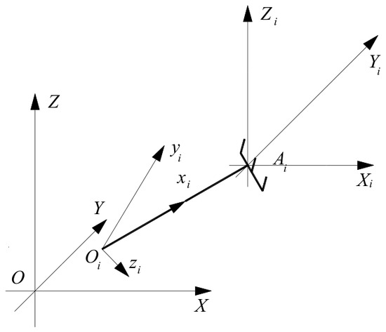
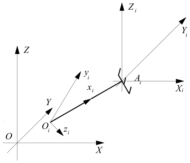
Let us consider an arbitrary generic bar, , the cantilever point being (Figure 1). The bar has the end embedded in a rigid solid (not represented in the figure). We assume that the bar is a straight one, has the length , is homogeneous and has a constant circular section, the diameter being . We also consider a reference system solidly linked to the rigid solid and another reference system having the axes parallel to those of the previous reference frame. Attached to the bar is considered another reference system with the axis along the bar orientated from the point to the point , the axes and being perpendicular to one another and perpendicular to the axis . The system contains bars.
Figure 1.
Mechanical model. Only one generic bar is represented.
We will denote the following:
- -
- —the rigidity matrix of the bar in the system [22],where is the longitudinal modulus of elasticity for the bar , and is the shear modulus of the bar . , and are the geometric moments of inertia of the bar , while is the area of the cross section of the same bar.
- -
- —the flexibility matrix, the inverse of the rigidity matrix of the bar (also calculated in the local reference frame ) [22],
- -
- —the matrix of rotation of the system with respect to the system ,where , , and are the cosines of the angles formed by axis with the axes , , and , respectively (or, equivalently, with the axes , , and , respectively), , , and are the cosines of the angles formed by axis with the axes , , and , respectively (or, equivalently, with the axes , , and , respectively), and , , and are the cosines of the angles formed by axis with the axes , , and , respectively (or, equivalently, with the axes , , and , respectively); in other words, , , are the direction cosines of the local -axis with respect to the global , , axes, respectively.
- -
- —the column matrix of the forces that act upon the system of bars,where , , and , , are the components of the resultant force and, respectively, the resultant moment calculated with respect to the point .
- -
- —the matrices of deformation of the system, with respect to the reference frame ,where , and are the rotations about the axes , and , respectively, while , and are the displacements along the axes , and , respectively.
- -
- —the screw matrix of translation defined bywhere , , are the coordinates of the point with respect to the reference system .
- -
- —the passing matrix,where is the square matrix with all elements equal to .
- -
- —the matrix of rigidity of the bar in the reference system ,
We may write the equation of equilibrium of the rigid solid as
denoting now
it results in the equation
where from
If the points coincide, then one may consider , for any , and the matrices and take the simpler forms (the following relation holds true when the translation vector from to is zero).
3. Optimizations
Many optimization criteria can be considered. For example, someone may consider as an optimization criterion a minimal displacement in a certain direction of the common point of the bars. For this reason, the calculation below is a generic one, assuming the extreme of a displacement, with one or more components of the displacement column matrix depending on a parameter that can be, for example, the position of a bar, etc.
We take into account the following relations:
where is an arbitrary parameter.
For instance, if one wants to obtain the maximum or minimum value of with respect to a parameter , let us say the length of the bar 1, then one must solve the equation
where is the matrix with one line and six columns given by
It results in the equation
The reader may easily see that the solution of Equation (18) is now very difficult to be obtained.
One may determine the deformations, that is, the values of , , (the rotations about the , , or axes) and , , (the displacements along the , , or axes).
Generally speaking, some optimizations must be considered:
- (i)
- The positions of the bars and the mechanical characteristics of them in order to minimize the values of , , (that is, the rotations about the , , or axes), , , (that is, the displacements along the , , or axes), or only a part of them. The problem can be solved only numerically in the general case.
- (ii)
- The extreme values for certain parameters in the case when a new bar is added to the system (that is, where the new bar must be added such that certain parameters take extreme values). It is a particular case of the optimization presented above, when only the position of one bar can be modified.
- (iii)
- The extreme values of certain parameters in the case when some characteristics of one or more bar can vary. It can also be considered a particular situation of the first case when only some characteristics can vary.
The solution/solutions may be obtained analytically in very few and particular cases or by numerical calculation in most cases. One of these cases is given in Section 4.
Even if the solution can be obtained analytically, it is possible that the solution does not satisfy some additional criteria (for instance, it is not in the permitted domain of existence for some parameters (e.g., the length of one bar is too small, etc.)).
4. Particular Case
Let us consider that the system consists of one horizontal cantilever bar . The reference frame is with the axis horizontal (along the bar) and the axis being vertical ascendant, while the axis results for a dextrorsum system. The geometric and mechanical characteristics of the bar are , , , , , , and . The bar is acted on only by a vertical descendant force at its free end .
Equation (13) takes the form
where from , , , , , and , which are the well-known results from the strength of materials.
A case with two cantilever bars is presented in [23].
5. Numerical Simulation
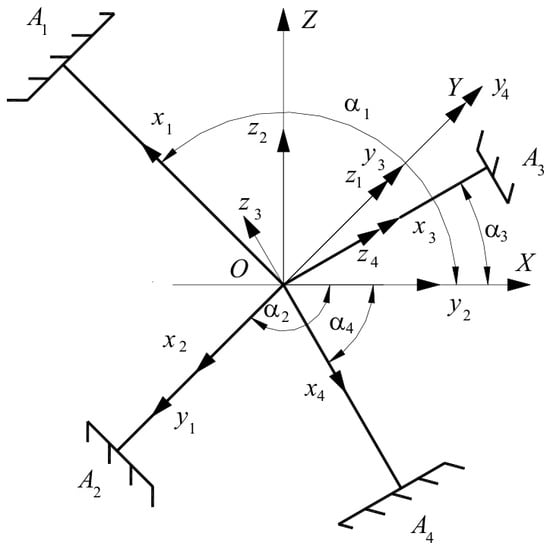
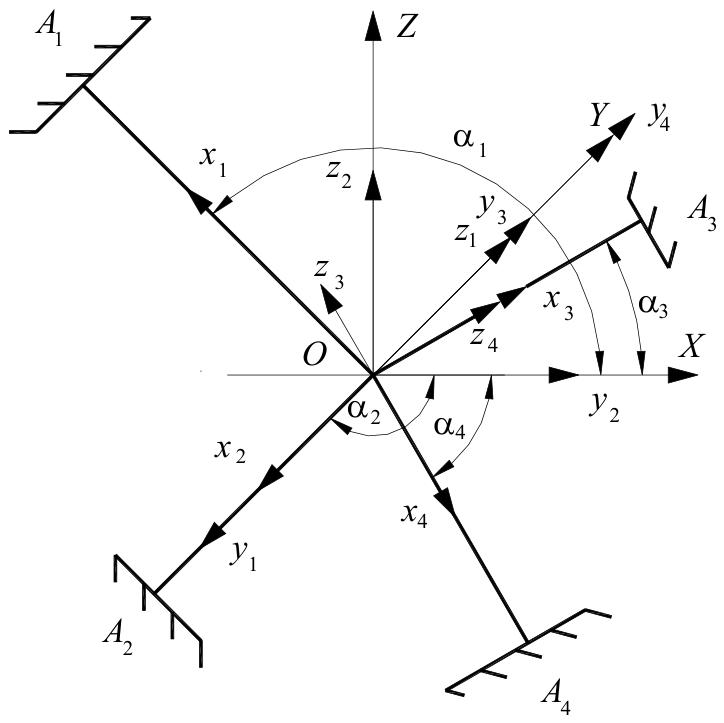
First of all, we consider that the system has four bars as follows (Figure 2). Bar is situated in the plane, bar is situated along the axis, bar is in the plane, and bar is in the plane; hence, three bars (denoted by 1, 3, and 4) are in the plane, while bar 2 is in the direction of the axis (opposite). The angles are (between the axis and the axis), (between the axis and the axis), (between the axis and the axis), and (between the axis and the axis). It results in the rotation matrices
Figure 2.
Numerical application.
If the lengths of the bars are , , then one gets the coordinates of the points , , with respect to the reference system as , , , , , , , , , , , and .
The following values are considered as standard values in the next simulations: diameters of bars , moduli of elasticity , lengths of bars , and shear moduli . The system is acted on by the force , vertical descendant.
Some results are given in what follows (Table 1).
Table 1.
Results of simulation for the first situation (system of four bars).
The deformations are , , , , , and .
One may conclude the following:
- -
- There exists no explicit rule to determine the displacements (angular or linear) in the general case, that is, using Equation (13); the vanishing of a certain displacement implies the existence of a certain relation between the geometric and mechanical parameters of the bars and the components of the force and torque that act at the common end.
- -
- The presence of new components of the force changes the displacements, but there is not a proportional increase in them. For instance, if the force has components along the three axes (the second situation) one may observe that rotation about the axis approximate doubles, the rotation about the axis is approximately four times bigger (absolute value), and for the rotation about the axis the values are approximately equal. Similar remarks hold true for the linear displacements.
- -
- Comparing now the second situation to the third one the changes are more dramatic. For instance the rotation about the axis is approximately double, while the rotation about the axis diminishes (in absolute value). The comparisons may continue.
For the case of the introduction of a new bar, the fifth one, the geometric and mechanical parameters of this new bar are the same as for the previous four. The only unknown is its position. It is assumed that this new position is defined by three rotations about the three axes of coordinates. The rotation angles may have values between 0° and 20°. For these three angles is considered the same increment equal to 0.2°. The optimization is performed by numerical simulation (the analytical solution is impractical to be obtained for general systems of bars).
The reader may state the following (see Table 2):
Table 2.
Results of simulation for the second situation (addition of the fifth bar to the system of four bars).
- -
- The apparition of the fifth bar does not imply a great diminishing of some deviations. The explanation may be given by the constraint imposed on the position of this new bar.
- -
- It is not a rule by which one may determine at which angle the minimum value of a certain parameter may appear.
- -
- New components of the force do not imply a greater deformation of the system (in absolute values). Again, this remark may have as cause the imposed position of the fifth bar.
The last case is that described by variation in certain parameters of the four bars. The first case is that in which the diameters of the bars may vary. Each diameter may vary between a minimum value and a maximum value of with a step of . More situations are considered (these situations are also true for rest of the cases): only one diameter varies, two diameters vary, three diameters vary, and in the end, all diameters vary. In what follows are presented the results for the situations in which three diameters vary (diameters for bars 1, 2, and 3; the diameter of bar 4 is that presented before). The following notations are used: , where signifies the standard value for the diameter . It results that for each diameter the values of are situated between and . The results are presented in Table 3.
Table 3.
Results of simulation for the third situation (system of four bars, the diameters of the bars may vary).
For the situation in which the lengths of the bars may vary (assuming the same ) the results are given in Table 4.
Table 4.
Results of simulation for the fourth situation (system of four bars, the lengths of the bars may vary).
The last situation is that where the elasticity modules and shear modules vary. The same are considered. The results are given in Table 5.
Table 5.
Results of simulation for the fourth situation (system of four bars, the moduli of elasticity of the bars may vary).
Some conclusions may be presented:
- -
- The minimum value of a certain deformation is not obtained for the extreme values of a certain parameter for all bars. For instance, the minimum value of is obtained for different diameters of the four bars, some of them far away from the maximum possible.
- -
- Each bar has a specific contribution for the minimization of a specific parameter. There are bars without a significant contribution in the minimization of a certain parameter.
- -
- One may construct a system with less bars and having approximately the same certain deformation. It is possible that the other deformations may vary significantly, so that the procedure must be used carefully (for instance, one may compare the first line of Table 2 with the first line of Table 3, etc.).
One may construct other criteria of optimization which can be, for instance, a combination of the previously described ones. One such criterion can be the minimization of linear deformation, .
6. Conclusions
This paper presents a general method to determine the displacement of the common point of a system of cantilever bars. The method may be applied for any system of cantilever beams with one common point. In the general case the deformation has three linear components and three rotational components.
The method is based on the use of screw coordinates. The components of the deformations are small, so the general formulas from the strength of materials may be applied. In an arbitrary situation one cannot say from the beginning that one system of cantilever bars with one common end has small deformations. If the deformations obtained by the application of the method are small, then one may conclude that the system has small deformations.
The optimizations presented in this paper are usually met in practice. It is clear that the solution cannot be obtained in closed form, and the application of numerical calculation is required. It is not clear whether reducing the iteration step size near a solution found with a coarser step would yield a better optimum. Addition of a new bar may not lead to diminishing of the absolute values of the components of deformation.
The results of the optimization depend on the steps of iterations. For instance, changing the step of angles from 0.2° to other values modifies the minima. Moreover, considering that the fifth bar can occupy any position (not between zero and twenty degrees), the minimum values and the position where they appear change very much.
Funding
This research received no external funding.
Data Availability Statement
No new data were created or analyzed in this study. Data sharing is not applicable to this article.
Conflicts of Interest
The author declares no conflicts of interest.
References
- Răcășan, V.; Stănescu, N.-D. On Spatial Systems of Bars Spherically Jointed at Their Ends and Having One Common End. Mathematics 2024, 12, 2680. [Google Scholar] [CrossRef] [Scilit]
- Hwang, Y.-L. Dynamic recursive decoupling method for closed-loop flexible mechanical systems. Int. J. Non-Linear Mech. 2006, 41, 1181–1190. [Google Scholar] [CrossRef] [Scilit]
- Marques, F.; Roupa, I.; Silva, M.T.; Flores, P.; Lankarani, H.M. Examination and comparison of different methods to model closed loop kinematic chains using Lagrangian formulation with cut joint, clearance joint constraint and elastic joint approaches. Mech. Mach. Theory 2021, 160, 104294. [Google Scholar] [CrossRef] [Scilit]
- Sorgonà, O.; Cirelli, M.; Giannini, O.; Verotti, M. Comparison of flexibility models for the multibody simulation of compliant mechanisms. Multibody Syst. Dyn. 2024, 63, 453–474. [Google Scholar] [CrossRef] [Scilit]
- Chen, J.; Chen, Q.; Liang, D.; Mo, J. Solution of geometrico-static problems and motion experiments for a suspended under-constrained parallel mechanism driven by two flexible cables. J. Mech. Sci. Technol. 2024, 38, 4365–4376. [Google Scholar] [CrossRef] [Scilit]
- Gallardo-Alvarado, J. Jerk distribution of a 6-3 Gough-Stewart platform. Proc. Inst. Mech. Eng. Part K J. Multi-Body Dyn. 2013, 217, 77–84. [Google Scholar] [CrossRef] [Scilit]
- Zhou, H.; Cao, Y.; Li, B.; Wu, M.; Yu, J.; Chen, H. Position-Singularity Analysis of a Class of the 3/6-Gough-Stewart Manipulators based on Singularity-Equivalent-Mechanism. Int. J. Adv. Robot. Syst. 2012, 9, 1–9. [Google Scholar] [CrossRef] [Scilit] [PubMed]
- Ding, X.; Isaksson, M. Quantitative analysis of decoupling and spatial isotropy of a generalised rotation-symmetric 6-DOF Stewart platform. Mech. Mach. Theory 2023, 180, 105156. [Google Scholar] [CrossRef] [Scilit]
- Šika, Z.; Krivošej, J.; Vyhlídal, T. Three dimensional delayed resonator of Stewart platform type for entire absorption of fully spatial vibration. J. Sound Vib. 2024, 571, 118154. [Google Scholar] [CrossRef] [Scilit]
- Hajimirzaallan, H.; Ferraresi, C.; Moosavi, H.; Massah, M. An analytical method for the inverse dynamic analysis of the Stewart platform with asymmetric-adjustable payload. Proc. Int. Inst. Mech. Eng. Part K J. Multi-Body Dyn. 2013, 227, 162–171. [Google Scholar] [CrossRef] [Scilit]
- Leonov, G.A.; Zegzhda, S.A.; Zuev, S.M.; Ershov, B.A.; Kazunin, D.V.; Kostygova, D.M.; Kuznetsov, N.V.; Tovstik, P.E.; Tovstik, T.P.; Yushkov, M.P. Dynamics and Control of the Stewart platform. Dokl. Phys. 2014, 59, 405–410. [Google Scholar] [CrossRef] [Scilit]
- Korkealaakso, P.; Mikkola, A.; Rantalainen, T.; Rouvinen, A. Description of joint constraints in the floating frame of reference formulation. Proc. Inst. Mech. Eng. Part K J. Multi-Body Dyn. 2009, 223, 133–145. [Google Scholar] [CrossRef] [Scilit]
- Bouzgarrou, B.C.; Ray, P.; Gogu, G. New approach for dynamic modeling of flexible manipulators. Proc. Inst. Mech. Eng. Part K J. Multi-Body Dyn. 2005, 219, 285–298. [Google Scholar]
- Huang, Z.; Zhao, Y.; Liu, J. Kinetostatic Analysis of 4-R (CRR) Parallel Manipulator with Overconstraints via Reciprocal-Screw Theory. Adv. Mech. Eng. 2010, 404960. [Google Scholar] [CrossRef] [Scilit]
- Hu, Y.; Zhang, H.; Wang, K.; Fang, Y.; Ma, C. Analytical analysis of vibration isolation characteristics of quasi-zero stiffness suspension backpack. Int. J. Dyn. Control 2024, 12, 4387–4397. [Google Scholar] [CrossRef] [Scilit]
- Chen, W.; Wang, S.; Li, J.; Lin, C.; Yang, Y.; Ren, A.; Li, W.; Zhao, X.; Zhang, W.; Guo, W.; et al. An ADRC-based triple-loop control strategy of ship-mounted Stewart platform for six-DOF wave compensation. Mech. Mach. Theory 2023, 184, 105289. [Google Scholar] [CrossRef] [Scilit]
- Yang, S.; Xu, P.; Li, B. Design and rigid-flexible dynamic analysis of a morphing wing eight-bar mechanism. Nonlinear Dyn. 2024, 112, 15025–15060. [Google Scholar] [CrossRef] [Scilit]
- Chen, G.; Rui, X.; Abbas, L.K.; Wang, G.; Yang, F.; Zhu, W. A novel method for the dynamic modeling of Stewart parallel mechanism. Mech. Mach. Theory 2018, 126, 397–412. [Google Scholar] [CrossRef] [Scilit]
- Xu, A.; Xu, Z.; Zhang, H.; He, S.; Wang, L. Novel coarse and fine stage parallel vibration isolation pointing platform for space optics payload. Mech. Syst. Signal Process. 2024, 213, 111359. [Google Scholar] [CrossRef] [Scilit]
- Jiang, Y.; Xiao, H.; Yang, G.; Guo, H.; Liu, R.; Deng, Z. Study on transient dynamics of the pyrotechnic-driven large flexible expansion mechanism. Nonlinear Dyn. 2024, 112, 15917–15932. [Google Scholar] [CrossRef] [Scilit]
- Beléndez, T.; Neipp, C.; Beléndez, A. An integrated project for teaching the post-buckling of a slender cantilever bar. Int. J. Mech. Eng. Educ. 2024, 32, 78–92. [Google Scholar] [CrossRef] [Scilit]
- Pandrea, N. Elements of Mechanics of Rigid Solids in Plűckerian Coordinates; The Romanian Academy Publishing House: Bucharest, Romania, 2000; ISBN 973-27-0764-X. [Google Scholar]
- Lee, K.T. Vibration of two cantilever beams clamped at one end and connected by a rigid body at the other. J. Mech. Sci. Technol. 2009, 23, 358–371. [Google Scholar] [CrossRef] [Scilit]

Disclaimer/Publisher’s Note: The statements, opinions and data contained in all publications are solely those of the individual author(s) and contributor(s) and not of MDPI and/or the editor(s). MDPI and/or the editor(s) disclaim responsibility for any injury to people or property resulting from any ideas, methods, instructions or products referred to in the content. |
© 2026 by the author. Licensee MDPI, Basel, Switzerland. This article is an open access article distributed under the terms and conditions of the Creative Commons Attribution (CC BY) license.