


Abstract
The lateral abutment stress and damage range of the coal seam are prerequisites for the layout of gob-side entries and surrounding rock control. They are influenced by the structure and mechanical properties of the coal seam and the overlying strata. To address this issue, this study establishes a mechanical analysis model for the lateral abutment stress and damage range under coupled conditions between the coal seam and overlying strata. This model systematically investigates the influence of various factors, including the fracture height and break angle of the overlying strata, the rotation angle and subsidence of key blocks, the burial depth and thickness of the coal seam, as well as the cohesion and internal friction angle of the coal mass. The study reveals that the weight and overburden load of the triangular hanging roof zone, along with the subsidence and rotation of the key blocks, are the key factors influencing the lateral abutment stress and damage range. Meanwhile, the reliability of the mechanical model has been substantiated through a combination of numerical simulation and in situ monitoring results.
MSC:
26A33; 74S40
1. Introduction
In mining engineering, the occurrence conditions of coal-rock and the excavation systems are complex. The damage degree of coal masses varies across different locations, resulting in complex and variable stress conditions in the coal seams. Due to its convenience for acquisition and analysis, vertical abutment stress is widely used as an important quantitative indicator. It is applied to assess the stress environment and damage state of coal-rock, reveal disaster mechanisms, and guide surrounding rock control [1]. Typically, based on the location and direction of abutment stress in the mining space, it is categorized into front abutment stress and lateral abutment stress (LAS). Among these, LAS holds significant importance for the layout of gob-side entry (GSE) in longwall mining systems, the stability control of surrounding rock, and the prevention of rock bursts [2].
The main research methods for abutment stress include numerical simulation, physical simulation, field measurement and theoretical analysis. Numerical simulation can comprehensively consider coal seam thickness, burial depth, mechanical properties, as well as overlying rock occurrence characteristics, fracture structures and mechanical properties. It is thus widely applied [3,4,5]. Field measurement [6] is affected by multiple factors. These include the structure of borehole stress meters and the fit between boreholes and stress meters. It is difficult to obtain absolute abutment stress values. Therefore, researchers usually analyze its evolution law by exploring the variation in abutment stress under mining influence [7,8,9]. They also indirectly reflect abutment stress values based on apparent stress represented by microseismic frequency and energy [10]. Physical simulations mostly take plane strain as the theoretical premise to build physical models [11,12]. The obtained results of abutment stress and damage range show deviations compared with actual engineering practices. Theoretical research plays an important role in quantitatively grasping the distribution law and formation mechanism of abutment stress. Currently, scholars continue to advance the development of related theoretical models.
Existing theoretical models for abutment stress can be broadly categorized into two types. The first type starts from the mechanical behavior of the coal-rock, simplifies the influence of overlying strata on ground pressure, and establishes stress boundary conditions for coal-rock through parameters such as stress concentration factors and disturbance indices. The second type focuses on the structure of the overlying strata, downplaying the influence of thickness, mechanical properties, and damage of the coal seam on abutment stress.
Within the first category, the limit equilibrium theory of coal seams is the most widely applied. This theory based on the stress limit equilibrium of coal in the plastic zone, deriving the peak value and location of the abutment stress [13,14]. Other models in this category include an analytical model based on statistical damage mechanics and prescribed deformation applied to coal units [15,16]; a viscoelastic model constructed using rheological theory [17]; and a discontinuous model established by defining coal-rock brittleness and disturbance indices based on ground pressure drop [18].
The second category includes several typical theoretical models. The internal and external stress field theory proposes differences in stress environments due to varying overlying strata structures on either side of the fracture line of the main roof [19,20,21]. The key stratum theory analyzes load transfer through hard key strata and its impact on abutment stress [22,23,24]. The cantilever beam model simplifies the main roof as a plane beam to explore its influence on the ground pressure [25]. The pressure arch model examines the effect of the “arch foot” on the stresses in the coal seam [26]. The end of the GSE model analyzes abutment stress based on the overlying strata structure at the triangular sliding zone [27].
Stress induces coal mass failure, which in turn modulates ground pressure transmission in the overlying strata and abutment stress distribution. In the failure mechanism of GSEs, extensive research focuses on the fracture location of the main roof [28] and the occurrence state of key blocks [29]. Theories including but not limited to elastoplastic theory [30], loosening zone theory [31,32], and energy evolution theory [33] also serve as applicable approaches for analyzing surrounding rock failure of the GSEs.
In comparison with conventional independent analysis approaches for coal seams and overlying strata, this coupled analysis model features the following merits:
- (a)
- Multiple factors can be comprehensively considered, including the occurrence and mechanical properties of the coal seam and overlying strata, such as thickness, cohesion and internal friction angle of the coal seam, mechanical strength and fracture height and angle of the overlying strata.
- (b)
- The mechanical interaction between overlying strata and coal seam is realized. It reflects the ground pressure transmission from overlying strata to underlying coal mass, while also considering the control of coal mass on the support and deflection deformation of overlying strata.
- (c)
- This mechanical model can take into account the mutual interaction between the dynamic damage of coal mass and LAS.
- (d)
- Dynamic influence principles of overlying strata on the LAS and DR, as well as the formation mechanism under different engineering geological conditions can be revealed.
The engineering practical significance of this model for GSE layout is as follows:
- (a)
- The distribution characteristics of LAS can be accurately determined, thus avoiding high LAS affected zones and selecting areas conducive to surrounding rock stability control.
- (b)
- The DR of the coal mass at the layout location of GSEs can be clarified, thereby quantitatively guiding the determination of the length and position of bolt cables.
- (c)
- Roof presplitting or roof cutting technologies can be applied to guide the reconstruction of the large structure of the overlying strata above GSEs, which in turn optimizes the LAS.
Based on the above analysis, this study establishes a mechanical model. It considers the combined effects of multiple factors. The model enables accurate grasp of the distribution law of LAS and the characteristics of coal seam damage range (DR). It systematically reveals the formation mechanism of LAS, thereby providing theoretical guidance for engineering applications in areas such as the layout of GSEs and the stability control of surrounding rock.
2. Mechanical Model
2.1. Mechanical Model Development
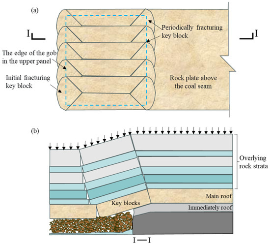
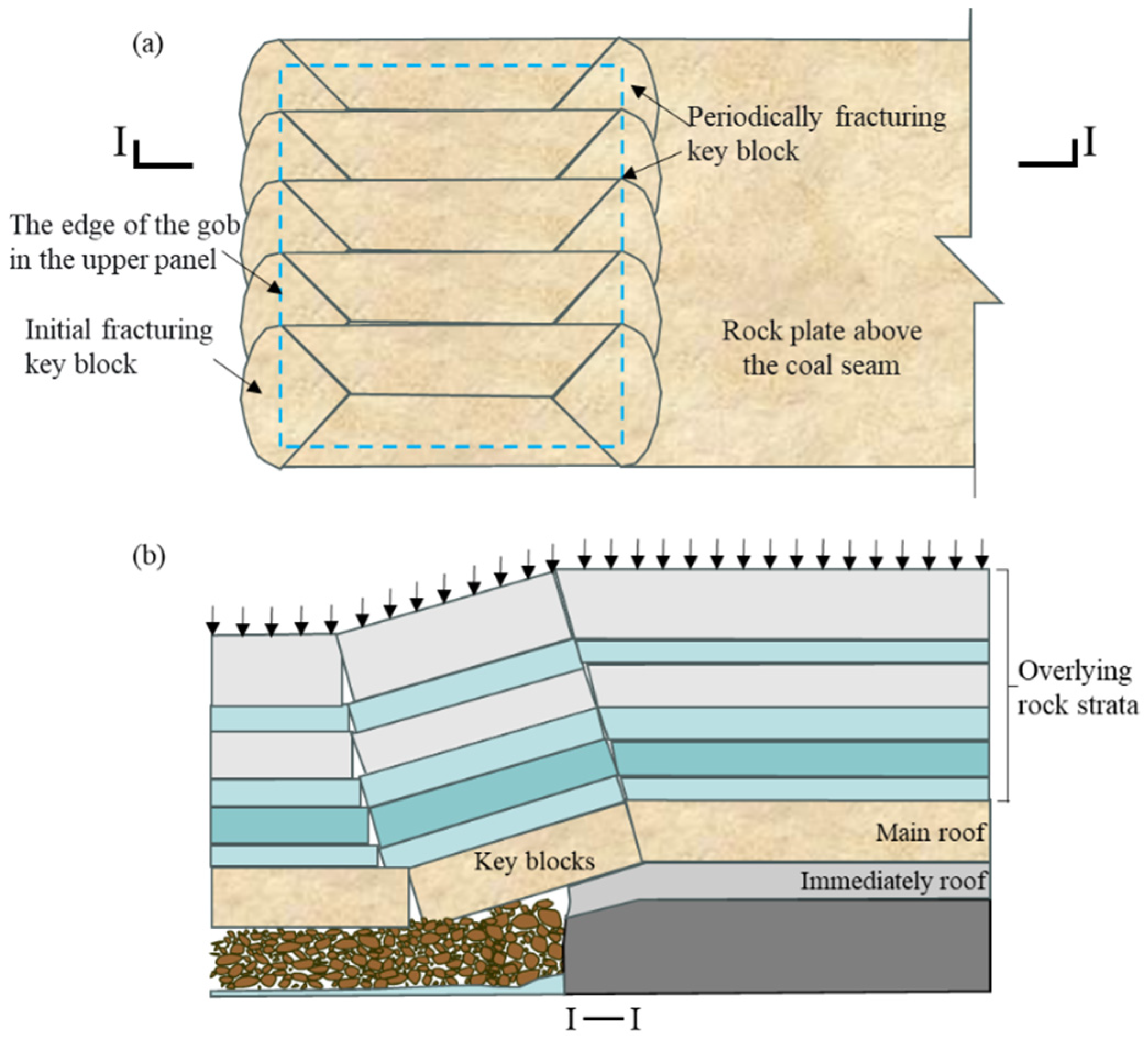
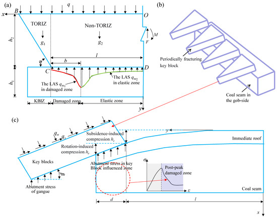
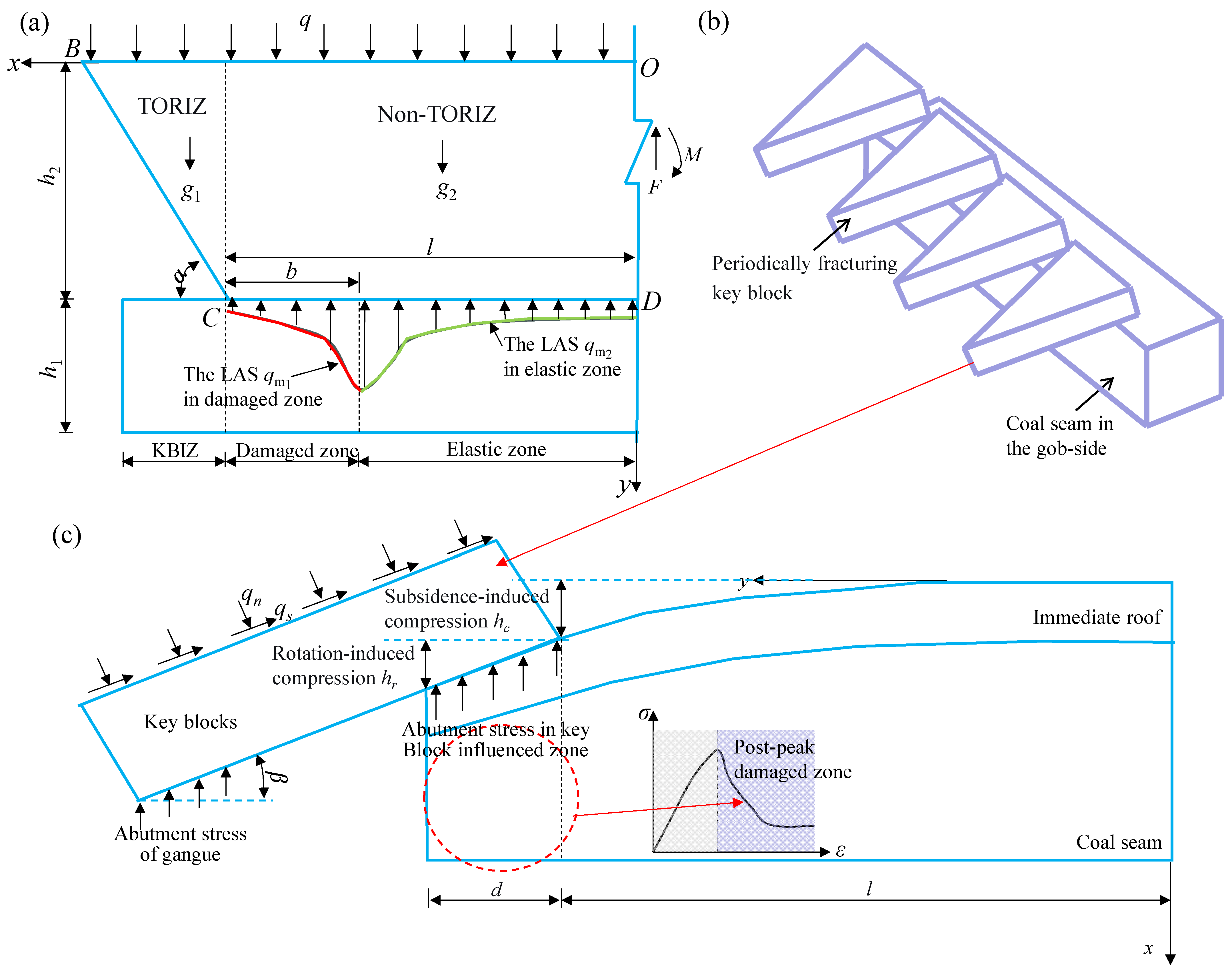
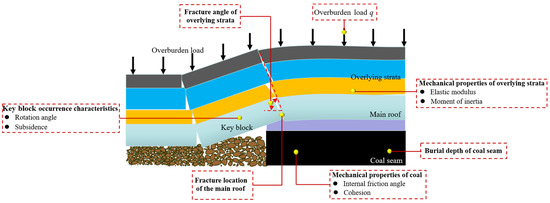
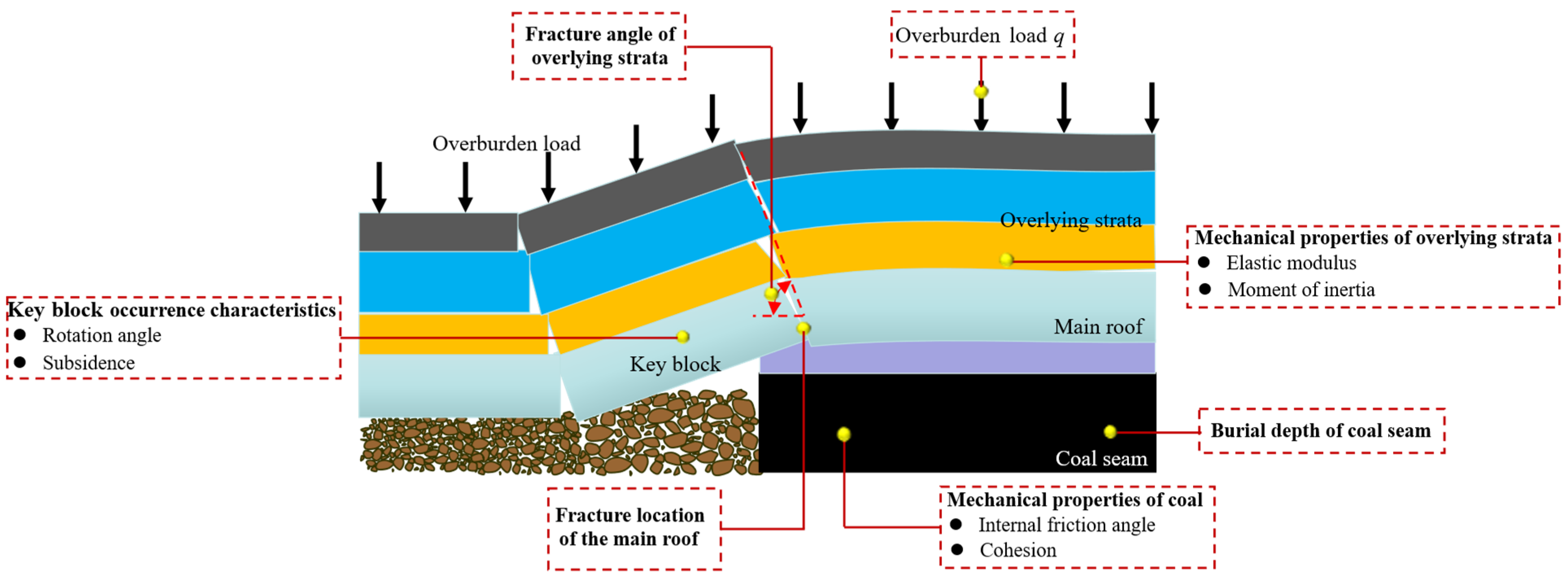
Numerous studies have demonstrated that the main roof overlying the GSE fractures into array-arranged initial and periodic fracture blocks, with its fractures propagating upward at a specific fracture angle [34], as shown in Figure 1. Based on the boundary condition and differences in the formation mechanism of LAS in the coal seam, the LAS is divided into two zones: the triangular overhanging roof influence zone (TORIZ) (Figure 2a) and the key blocks influenced zone (KBIZ) (Figure 2b,c).
Figure 1.
Structural characteristics of coal-rock on the gob-side entry. (a) Top view; (b) Side view.
Figure 2.
Analysis model of the lateral abutment stress and damage range. (a) Lateral abutment stress model in triangular overhanging roof influence zone; (b) Occurrence characteristics of key blocks formed by main roof fracture; (c) Lateral abutment stress model in key block influenced zone.
The interface of TORIZ and KBIZ corresponds to the location of the main roof fracture line. The division of the TORIZ and KBIZ interface is based on the movement of overlying strata, occurrence characteristics, and boundary conditions. Specifically, the fracture line is located along the goaf side, where the main roof breaks to form a key block. After fracturing, this key block undergoes rotation and subsidence, occurring at a certain dip angle in the goaf. The key block is supported by the goaf gangue rock, the underlying coal seam, and the load from the overlying strata. The overlying strata in the TORIZ experience flexural deformation under their self-weight and the overlying load. The boundary conditions for the overlying strata in this zone include the overlying load, the support stress from the underlying coal seam, and the displacement boundary condition at y axis.
The coal-rock structure and mechanical boundary conditions in the TORIZ remain consistent along the strike direction, allowing for plane strain mechanical analysis. In contrast, the KBIZ exhibits significant variations along the strike, necessitating 3D modeling. Based on the above analysis, a theoretical model of the DR and LAS of the coal seam as shown in Figure 2 is established.
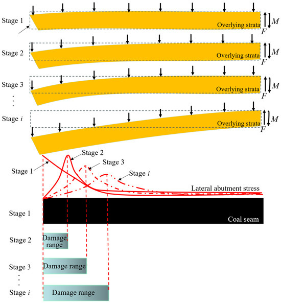
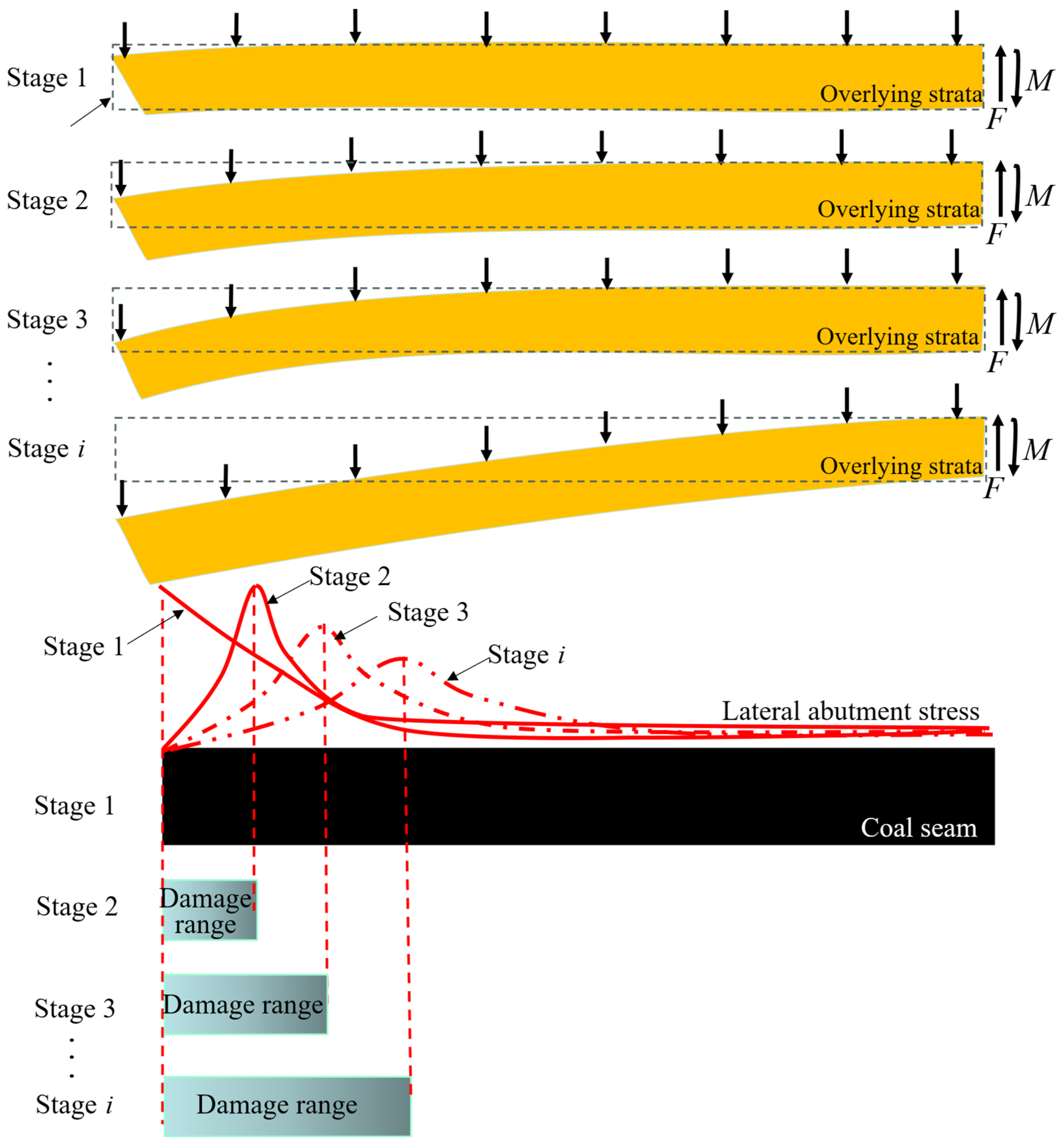
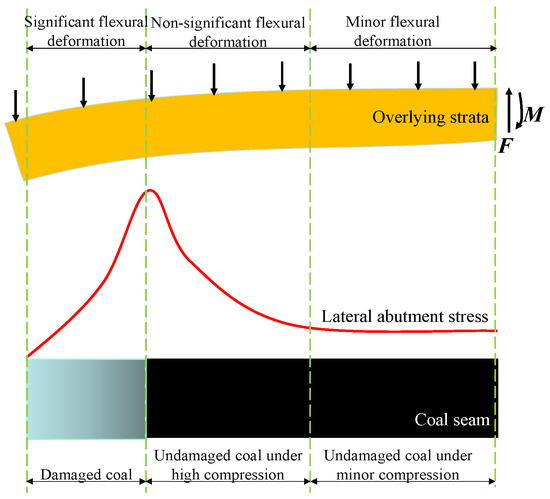
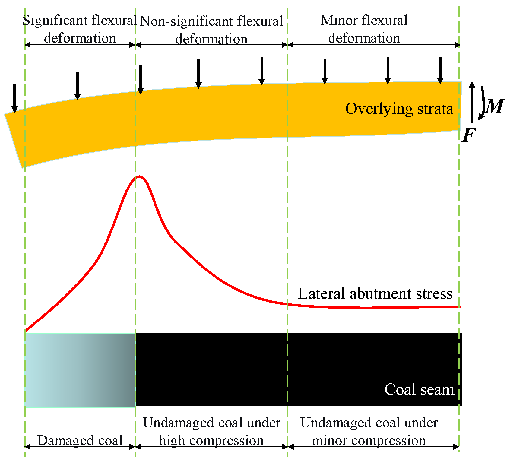
In TORIZ, the dynamic evolutionary relationship between abutment stress, coal mass damage and flexural deformation of overlying strata exhibits the characteristics as shown in Figure 3.
Figure 3.
Dynamic evolutionary relationship between abutment stress, damage range and flexural deformation of overlying strata.
- (a)
- In the initial stage (Stage 1), the overlying strata fracture, the suspended overlying strata bend under the overburden load and self-weight, and the forces in the overlying strata have not yet reached equilibrium. At this stage, the coal mass remains intact, and the LAS is distributed in the elastic coal seam.
- (b)
- As the bending deformation of the overlying strata increases (Stage 2 and Stage 3), the compressive deformation of the coal exceeds its limit, leading to failure. Simultaneously, with increasing bending of the overlying strata, its internal forces continue to rise. At this stage, the LAS presents a peak-shaped distribution, consisting of two components, the LAS in the damaged zone and that in the elastic zone.
- (c)
- When the deformation of the overlying strata and the damage range of the coal mass expand to a certain extent, the overlying strata achieve mechanical equilibrium under the combined action of the LAS and internal forces, eventually stabilizing.
Based on above dynamic evolutionary mechanism, the following mechanical analysis is presented.
Study [35] derived the LAS in the damaged zone of the coal seam. It is based on two key assumptions: first, that the interface between the coal seam and the roof/floor strata acts as a weak sliding surface; second, that the critical failure relationship between shear stress and normal stress at this interface holds true. The resulting LAS accurately describes the post-peak stress state of the coal and captures the influence of the coal mass’s stress state. This theoretical model has been widely validated through extensive engineering practice, numerical analysis, and physical modeling in mining engineering. Therefore, the LAS in the damaged zone under the TORIZ, denoted as qm1(x), can be determined as follows [35]:
where the A1, A2 and A3 are calculation parameters, given by:
where c0 and φ0 are cohesion and internal friction angle, As is the lateral pressure coefficient, they can be obtained through laboratory mechanical testing; Pz denotes the lateral resistance of the coal rib, it can be determined by the support resistance of the roadway rib;
where h1 presents the thickness of the coal seam;
Based on the theory of elasticity, the abutment stress qm2(x) in the coal mass of the elastic zone can be determined by:
where l is represents the influenced range of the TORIZ, it can be obtained through field observation such as borehole stress or numerical simulation; σd is the in situ stress of the coal seam, which can be obtained by ; q denotes the overburden load acting on the overlying strata, it can be calculated by , where hb is the burial depth of the coal seam; h2 is the height of the fractured overlying strata, it can be obtained based on the discrimination method provided in the study [36]; r1 is the radius of the hole, and its value can be determined by r1 = h1/2; T is the stress correction coefficient, which can be calculated by , b denotes the DR of the coal seam in the TORIZ.
The weight of the TORIZ g1 per unit length along the strike is as follows:
where γ denotes the average bulk density of the overlying rock, it is usually taken as 0.025 MN/m3; α is the fracture angle of the overlying strata, it can be obtained by field testing methods such as borehole imaging and microseismic monitoring, or by physical similarity models.
Similarly, the weight of the overlying strata g2 in the non-overhanging zone is:
Based on the vertical force equilibrium of the overlying strata, the following equation is obtained:
where l1 represents the length of the overlying strata at the top; F represents the internal shear force in the overlying strata.
Substituting Equations (1)–(4) into Equation (5) yields:
here .
The moment Mq about the coordinate origin O due to the overburden load q on the overlying strata is:
The moment Mg1 about point O due to the weight of the overlying strata in the TORIZ is:
The moment Mg2 about point O due to the weight of the overlying strata in the Non-overhanging roof zone is:
The moment Mqm1 about point O due to the abutment stress qm1 in the damaged zone of the coal mass is:
The moment Mqm2 about point O due to the abutment stress qm2 in the elastic zone of the coal mass is:
Based on moment equilibrium, the following equation can be established:
where M represents the bending moment within the fractured overlying strata.
Substituting Equations (7)–(11) into Equation (12) yields:
The deflection wg1(x) of the overlying strata at position x under the action of the gravitational force g1 is:
where E is the elastic modulus of the overlying strata; I is the moment of inertia of the overlying strata, which can be calculated by , h3 is the thickness of the load-bearing layer of the fractured overlying strata.
The deflection wg2(x) of the overlying strata at position x under the action of the gravitational force G2 is:
where θg2 is the rotation angle of the overlying strata at the position where the gravitational force g2 acts, satisfying .
The deflection wq(x) of the overlying strata at position x under the action of the overburden load q is:
The deflection wqm1(x) of the overlying strata at position x under the action of the LAS qm1 in the damaged zone of the coal seam is:
where , represent the internal shear force and bending moment, respectively, at the cross-section x = l − b of the overlying strata under the action of qm1, which can be determined by the following equations:
The deflection wqm2(x) of the overlying strata at position x under the action of the abutment stress qm2 in the elastic zone of the coal seam is:
where C11 and C12 are calculation parameters, given by:
Based on Equations (14)–(18), the deflection of the overlying strata at position x = l − b under the combined action of all forces can be obtained as follows:
The deformation of coal at the interface between the damaged and elastic coal mass is determined by the following equation:
where Em1 is the compression modulus of the elastic coal mass.
Based on the deformation compatibility between the overlying strata and the coal seam at the interface between the damaged and elastic coal masses, the coal seam and overlying strata structure are coupled, leading to the following relationship:
Substituting Equations (19) and (20) into Equation (21), the DR can be obtained, and the LAS can be further derived from Equations (1) and (2). Meanwhile, the shear internal force F and bending moment M at cross-section O of the overlying strata are calculated based on Equations (6) and (12).
Regarding the coal seam in the KBIZ, it is overlain by numerous periodically fractured key blocks, as illustrated in Figure 2b. Under substantial overburden loads, these key blocks undergo significant subsidence and rotational movement, imposing specified compressive deformation on the underlying coal seam. This results in severe damage to the coal mass, with its mechanical behavior entering the post-peak stress stage. Unlike the coal seam in the TORIZ, under the load of any key block, the underlying damaged coal mass can only bear a portion of the load corresponding to its degraded strength. The remaining load is supported by the caved gangue in the gob. Consequently, the LAS in the KBIZ is solely determined by the mechanical strength of the underlying damaged coal mass. Based on this, the mechanical model shown in Figure 2c is established.
The displacement boundary conditions of the coal mass can be determined by the imposed deformation resulting from the rotation and subsidence of the key blocks, thereby allowing an investigation into the DR of coal mass to ascertain the strength of the degraded coal mass. Based on the damage path obtained from mechanical tests of the coal mass, the constitutive relationship of the coal mass in this zone can be expressed [16]:
where σ1 and σ3 represent the normal and the confining stresses of the coal seam, respectively; Em2 is the compression modulus of the damaged coal; m and ε0 are the shape parameter and scale parameter and of the Weibull damage distribution, respectively; ε1 is the strain of coal mass. They can be obtained by laboratory mechanical tests.
The strain of the micro-unit coal mass is influenced by the occurrence characteristics of the key blocks. The compression of the coal induced by the key blocks is composed of two components, subsidence and rotation. Considering the continuity of coal mass compression at x = l, the subsidence component of key blocks is determined by hc1 (coal mass compression at x = l induced by overlying strata). This relationship is derived in the previous section:
The rotation-resulting compression of the coal mass can be determined based on geometric relationships using the following formula:
where the rotation angle of the key block is β, it can be determined by , hi is the thickness of immediate roof, hu is the unmined coal thickness, and λg is the gangue bulking coefficient; d is the distance from the main roof fracture line to the coal rib.
By combining both subsidence-induced and rotation-induced compression, the total compression of the coal seam due to the key block can be expressed as:
The compressive strain of the coal mass beneath the key block can then be further determined as:
Substituting Equation (26) into Equation (22) yields the LAS of the coal mass beneath the key block:
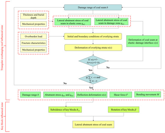
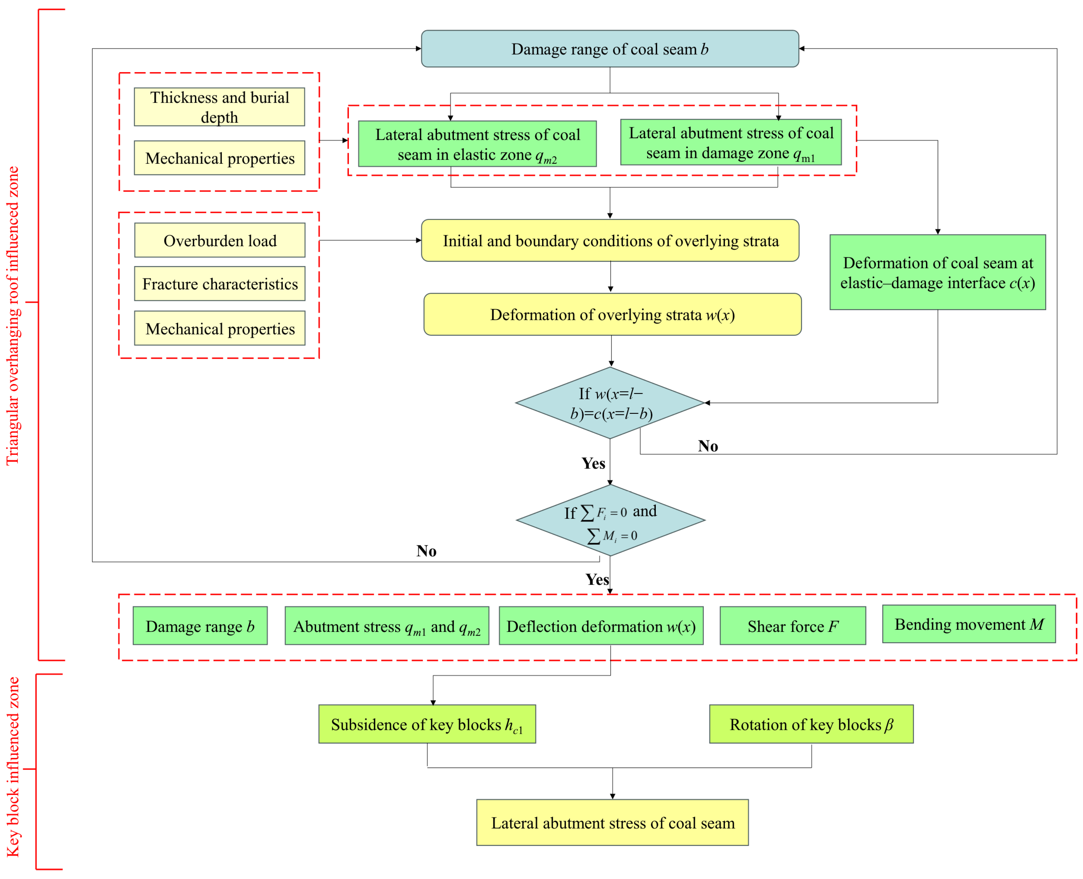
The coupling between overlying strata and the coal seam is mainly manifested in two aspects, the deflection of overlying strata and compressive deformation of the coal seam, as well as the continuous iterative feedback among overlying strata self-weight, overburden load, internal forces and LAS. Meanwhile, the damage zone in the coal seam evolves dynamically with the solution steps. This evolution, in turn, affects the deformation and stress of both overlying strata and the coal seam, ultimately leading to mechanical equilibrium and deformation coordination. For the proposed mechanical analysis model, as shown in Figure 4, its detailed analytical and solution steps, together with the logical flow, are as follows:
Figure 4.
Analysis and solution approaches for the mechanical model.
- (a)
- The control equations were implemented in Matlab R2024a, with initial mechanical and displacement conditions, along with boundary conditions, assigned to the overlying strata and coal seam based on engineering and geological parameters.
- (b)
- The initial value of the DR in the coal seam b was set to 0.
- (c)
- The LAS qm1 and qm2 in the coal seam were determined through solution.
- (d)
- The deflection deformation of the overlying strata under the current initial and boundary conditions was calculated, and the internal forces within the overlying strata were solved.
- (e)
- Based on Equation (21), the deformation coordination between the overlying strata and the coal seam at the elastic–plastic interface of the coal seam was assessed. If compatible, the process proceeded to the next step. If not, the process returned to step (b), with the damage range increased by 0.01 m, and the above steps were repeated.
- (f)
- The mechanical equilibrium of the overlying strata under the combined action of external and internal forces was evaluated. If equilibrium was achieved, the following parameters were exported: the coal damage range b, support stresses qm1 and qm2, deflection deformation of the overlying strata w(x), shear force F, and bending moment M. If not, the process returned to step (b), with the DR b increased by 0.01 m, and the above steps were repeated.
- (g)
- The deflection deformation of the overlying strata at x = l was input into the KBIZ to determine the subsidence of the key block.
- (h)
- Based on the rotation and subsidence values of the key block, the LAS in the underlying coal seam of the key block was solved.
2.2. Model Validation
To validate the reliability of the mechanical model, the engineering and geological conditions of the GSE 106 from the study [37] were applied. Using the mechanical model proposed in this study, the LAS distribution in the virgin coal rib of the GSE 106 was calculated. The results were then compared with the numerical simulation results presented in “Figure 17” of the study [37].
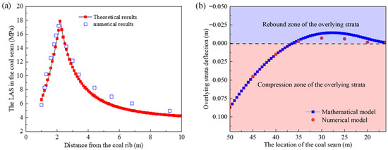
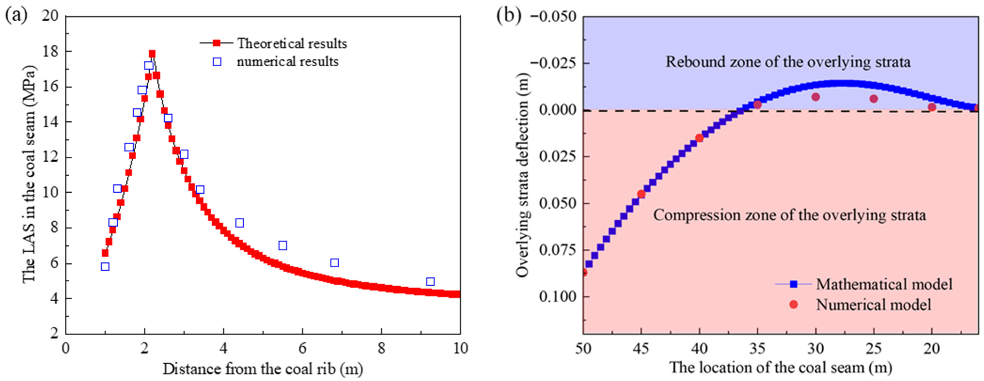
As shown in the results in Figure 5, the distribution principle of abutment stress in the coal seam obtained by the theoretical model in this study is generally consistent with the numerical results from the study [37]. The peak values from the theoretical calculation and numerical analysis are 17.11 MPa and 17.2 MPa, respectively, with an error of 0.52%. The plastic zone ranges are 2.3 m and 2.1 m, respectively, with an error of 9.5%. These data indicate that the mechanical model achieves computational accuracy comparable to the numerical analysis in the study [37]. By comprehensively considering the coal-rock structure and mechanical properties, this model can yield relatively accurate analytical results.
Figure 5.
Comparative Analysis of Theoretical and Numerical Results. Theoretical results versus numerical results of study: (a) Theoretical results versus numerical results [37]; (b) Theoretical and Numerical analysis of overlying strata deflection.
Meanwhile, it can be seen from Figure 5a that the post-peak stress of theoretical results is lower than that of the numerical analysis. The cause for this discrepancy lies in the fact that, under the given boundary and initial conditions, the overlying strata above the GSE undergo both compressive and rebound deformation, as illustrated in Figure 5b. Among these, the compressive deformation zone of the overlying strata is close to the coal rib and primarily affects the LAS in the post-peak stress decay zone, whereas the rebound deformation zone is farther from the coal rib and mainly influences the LAS in pre-peak stress growth zone.
In addition, as shown in Figure 5a, the post-peak stress obtained from the theoretical model is lower than that from the numerical simulation. This discrepancy occurs because, under the given boundary and initial conditions, the overlying strata above the GSE experience both compressive and rebound deformation, as depicted in Figure 5b. Specifically, the compressive deformation zone of the overlying strata, located closer to the coal rib, primarily influences the LAS in the post-peak stress decay zone. In contrast, the rebound deformation zone, situated farther from the coal rib, mainly affects the LAS in the pre-peak stress growth zone. In the theoretical model, the rebound deformation of the overlying strata is greater than that in the numerical model. This leads to reduced compression of the coal seam by the overlying strata, resulting in a lower LAS compared to the numerical simulation. Further analysis indicates that the distance from the model boundary to the coal rib is a key factor affecting the magnitude of rebound deformation. This distance in the model is set to 50 m along the y-axis to minimize boundary effects on accuracy, whereas in the numerical model, it is 40 m.
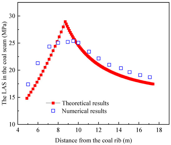
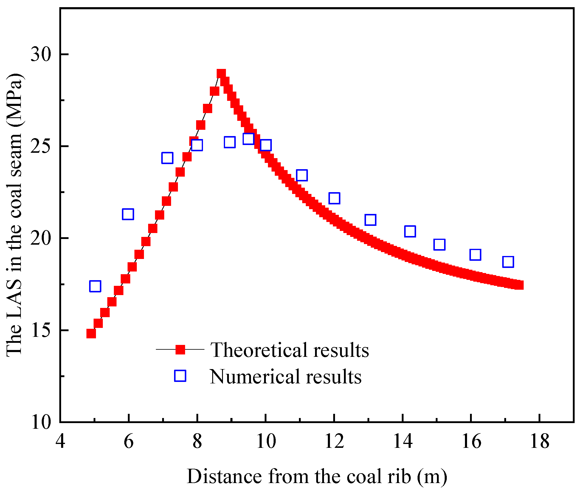
To verify the applicability of the mechanical model under different engineering geological conditions, the study further conducted a comparative analysis of the consistency of LAS distribution laws derived from the mechanical model and numerical simulation. This analysis was based on the engineering geological conditions of Qianyingzi Mine reported in Reference [38]. As shown in the results of Figure 6, the peak LAS determined by the theoretical model is 28.95 MPa, with its position at 8.7 m. In contrast, the numerical simulation yields a peak position of 9.5 m and a corresponding peak stress of 25.39 MPa. A comparison of the theoretical and numerical results indicates that the deviations of the peak stress and position from the theoretical calculations are 13.7% and 8.42%, respectively. These errors satisfy the mining engineering requirements.
Figure 6.
Theoretical results versus numerical results of study [38].
The LAS derived from the limit equilibrium theory does not take into account the constitutive relationship between stress and strain of the damaged coal mass, which is one of the causes for the deviation between the theoretical and numerical results, and this leads to the theoretical analysis results being lower than those of the numerical analysis.
3. Influencing Factors and Mechanisms
The controlled variable method is employed to investigate the influencing factors and mechanisms of the LAS and DR in the coal seam. The relevant parameters in the model are listed in Table 1.
Table 1.
Parameters in the model.
3.1. Influence Principles and Mechanisms in Key Block Influenced Zone
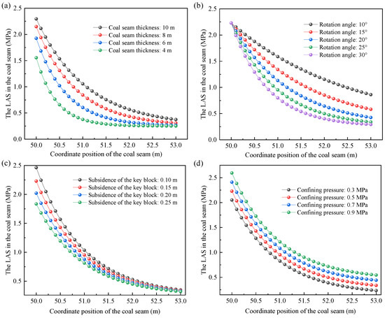
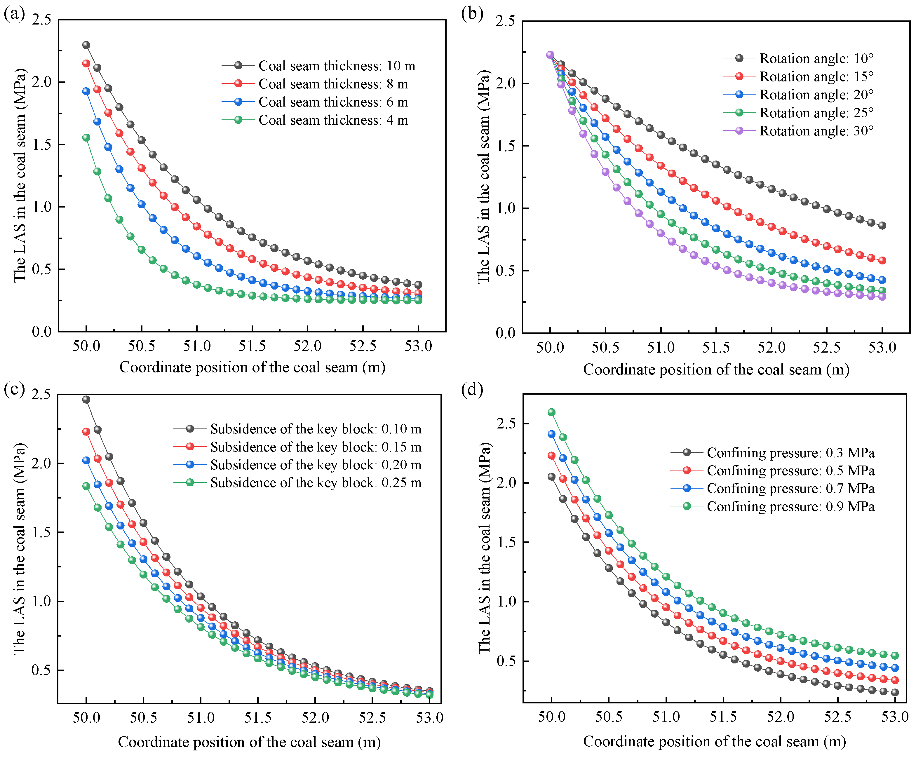
As shown in Figure 7a, the LAS in the KBIZ of the 10 m extra-thick coal seam is significantly higher than that of the 4 m coal seam. Moreover, the LAS near the fracture line (2.5 MPa) exceeds that at the coal rib (0.37 MPa). Similar principles are observed in other thicknesses of the coal seam. The theoretical model reveals that the greater the coal seam thickness, the smaller the compressive strain induced by the key blocks, resulting in reduced degradation of the coal mass. Consequently, the LAS in thick coal seams beneath key blocks is higher than that in thin coal seams.
Figure 7.
Influence principles of various factors in the key-blocks-influenced zone on lateral abutment stress. (a) Coal seam thickness; (b) Key-block rotation angle; (c) Key-block subsidence; (d) Confining stress of the coal mass.
The rotation angle of the key block directly influences the compressive deformation of the coal mass. As shown in Figure 7b, a larger rotation angle leads to more severe damage in the underlying coal mass, resulting in a lower LAS. However, the influence of the key block rotation on the LAS near the coal rib gradually diminishes (Figure 7b). This behavior occurs because the coal mass at the coal rib experiences increased damage due to the rotation of the key block. Once the coal mass approaches its residual strength, its response no longer changes with further rotation of the key block.
The influence of key-block subsidence on the LAS follows a similar pattern to that of the key-block rotation angle (Figure 7c). Greater subsidence of the key block results in lower LAS, with a more pronounced effect observed near the fracture line compared to the coal rib. Furthermore, mechanical tests have demonstrated that the coal mass exhibits higher load-bearing capacity under elevated confining pressure. Consequently, as shown in Figure 7d, a higher confining pressure leads to increased LAS in the coal mass underlying the KBIZ.
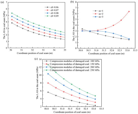
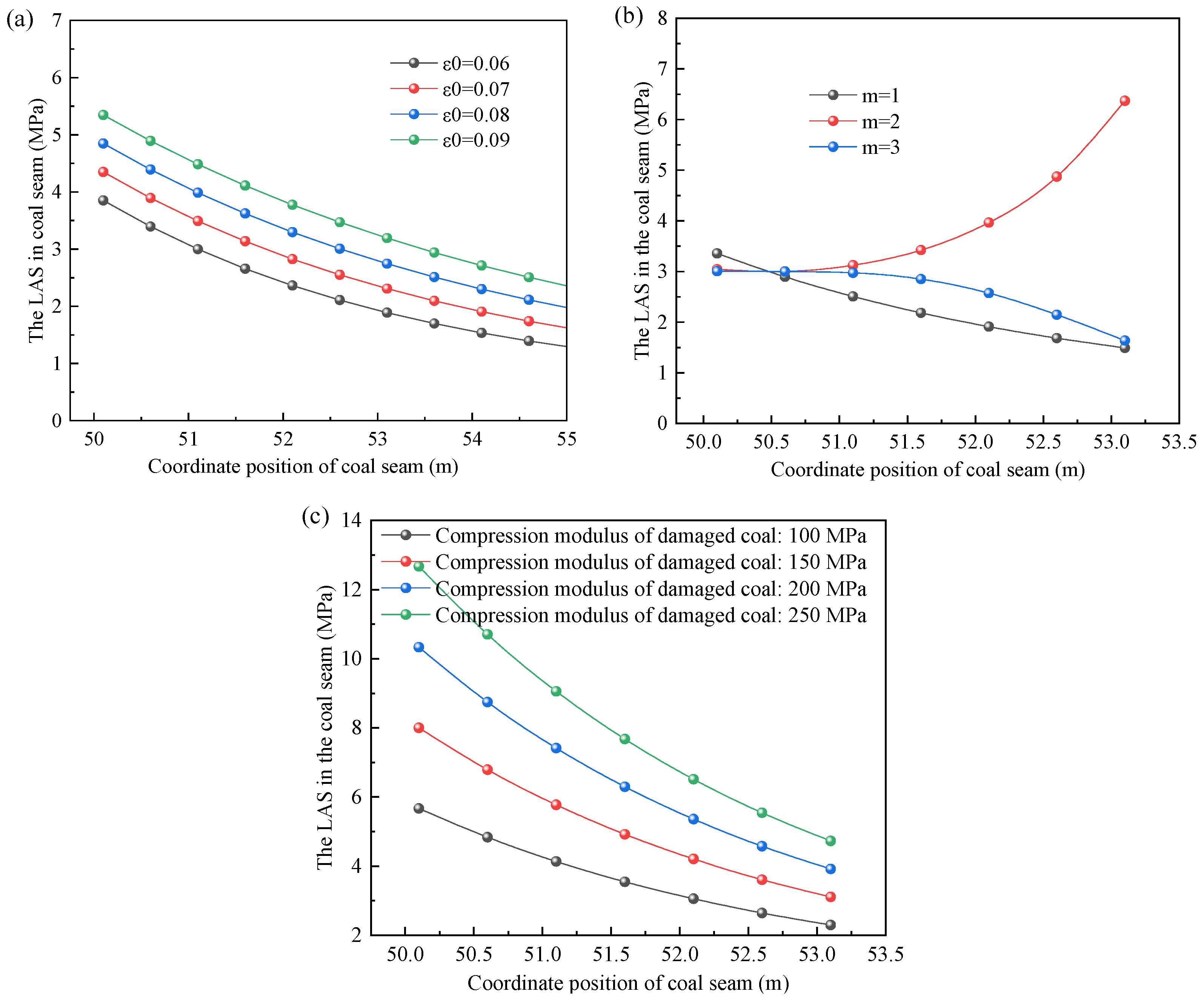
Figure 8 illustrates the influence of different constitutive parameters of damaged coal on the LAS. The Weibull damage parameter ε0 does not alter the distribution pattern of the LAS in the coal seam, but it affects its magnitude. The larger the value of ε0, the greater the LAS, as shown in Figure 8a. As can be seen from Figure 8b, the Weibull damage parameter m not only affects the magnitude of the lateral supporting stress but also influences its distribution pattern. When m takes values of 1 and 3, the LAS decreases with increasing distance from the coal seam coordinate. In contrast, when m = 2, the variation in LAS is contrary to the aforementioned pattern. The compression modulus of the coal mass is proportional to the LAS. However, the increase in LAS due to a higher compression modulus is more pronounced near the coal rib compared to locations farther away, as shown in Figure 8c.
Figure 8.
Effect of the damage constitutive parameters of coal on lateral abutment stress. (a) Weibull damage parameter ε0; (b) Weibull damage parameter m; (c) Compression modulus of damaged coal.
3.2. Influence Principles and Mechanisms in Triangular Overhanging Roof Influenced Zone
3.2.1. Coal Seam Thickness
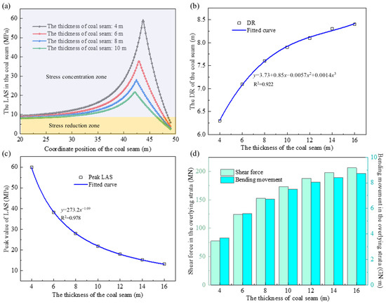
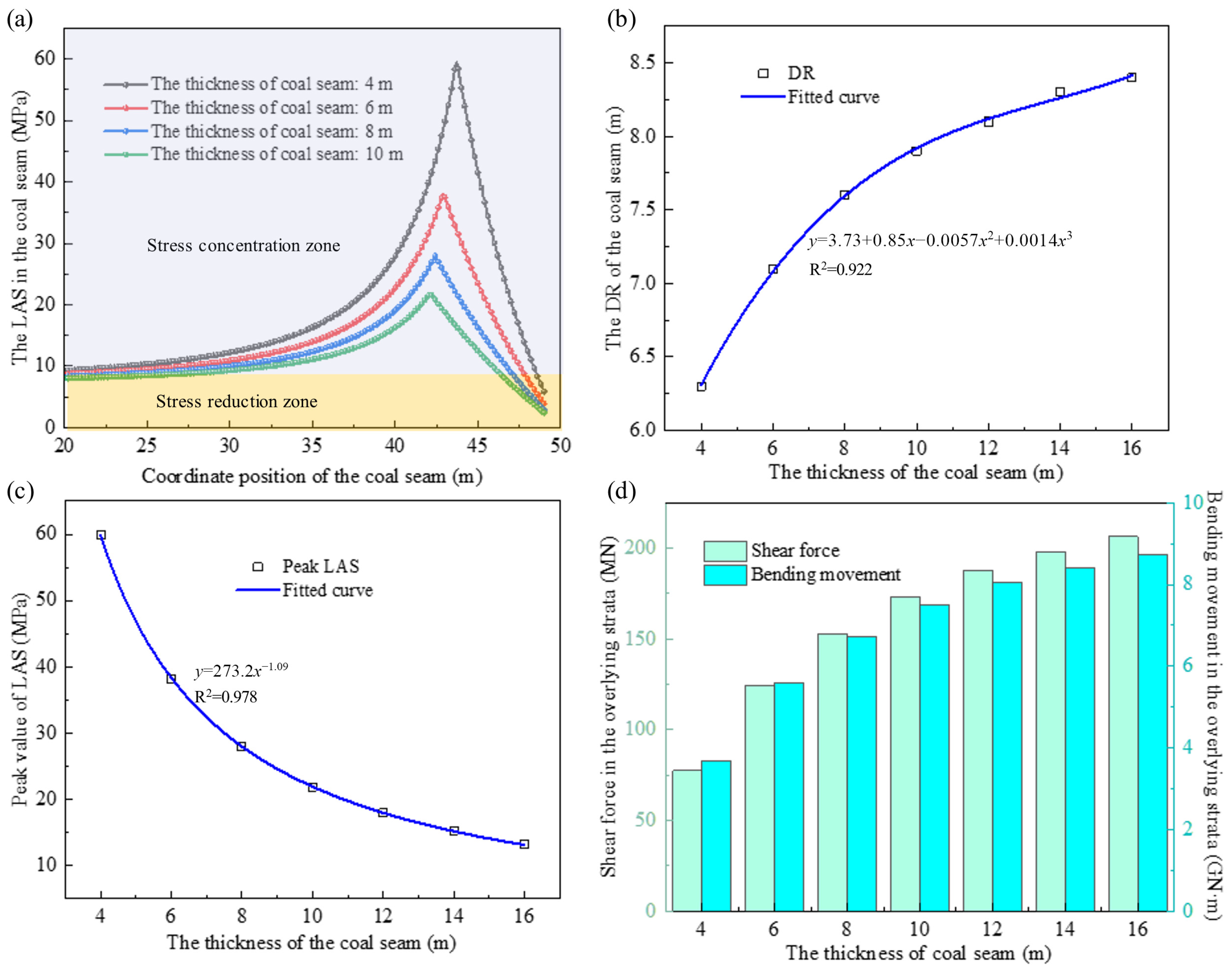
Figure 9a,b demonstrate that the DR of the coal seam on the gob-side exhibits a non-linear positive correlation with its thickness. However, for extra-thick coal seams with thicknesses exceeding 8 m, the increase in the DR is not significant when the thickness further increases, but the peak LAS decreases with coal seam thickness. Based on the stress-gradient reduction rate, it can be observed that the peak LAS is more sensitive to thick coal seams than to extra-thick coal seams (as shown in Figure 9a,c). Here, the relationship between coal seam thickness and the peak LAS follows a negative exponential power function y = axb (where a > 0 and b < 0). In this calculation example, a = 273.2 and b = −1.09, which aligns with the principle reported in study [38] regarding the variation in peak LAS with coal seam thickness. Meanwhile, study [39] indicates that the peak LAS in thick and extra-thick coal seams is lower than that in thin or ordinary thick coal seams. It is consistent with the findings of this study, further validating the reliability of the mechanical model.
Figure 9.
Relationship between the thickness of coal seam and the damage range and lateral abutment stress. (a) Distribution characteristics of lateral abutment stress; (b) Influence on damage range; (c) Influence on peak lateral abutment stress; (d) Internal forces of overlying strata at O position.
The primary reason for the aforementioned decrease in the peak LAS with coal seam thickness is as follows: the DR in thick coal seams is larger than that in ordinary coal seams, causing the peak LAS to shift deeper into the coal seam. The extensive damaged zone distributes part of the overlying strata load.
Meanwhile, as shown in Figure 10, thick coal seams exhibit greater compressible deformation, enabling significant deflection of the overlying strata. Larger deflection induces higher internal forces (F and M) in these strata. This means the overlying strata bear a larger share of the overburden load and their own self-weight. Based on the mechanical equilibrium principle, under the same overburden load and strata self-weight, the more load the overlying strata bear, the less ground pressure is transferred to the coal seam. As a result, the peak LAS in the coal seam is reduced (see Figure 9d).
Figure 10.
Relationship between overlying strata deflection, lateral abutment stress, and damage zone.
In mining practice, the ground pressure behavior in extra-thick coal seams is more intense than that in ordinary coal seams, and the larger the seam thickness, the greater the influence range of the LAS elevation zone [40]. This observation contradicts the relationship between coal seam thickness and LAS described in early studies. The primary reason is that an analysis focusing solely on coal seam thickness fails to consider the influence of the overlying strata structure. The thickness of the coal seam directly affects the location and height of fracture and collapse in the overlying strata. Therefore, investigating the LAS in coal seams requires comprehensive consideration of the overlying strata characteristics.
3.2.2. Mechanical Properties of Coal Seam
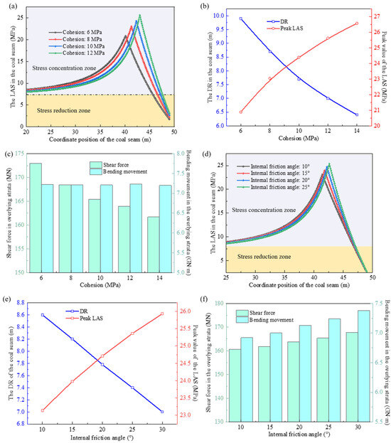
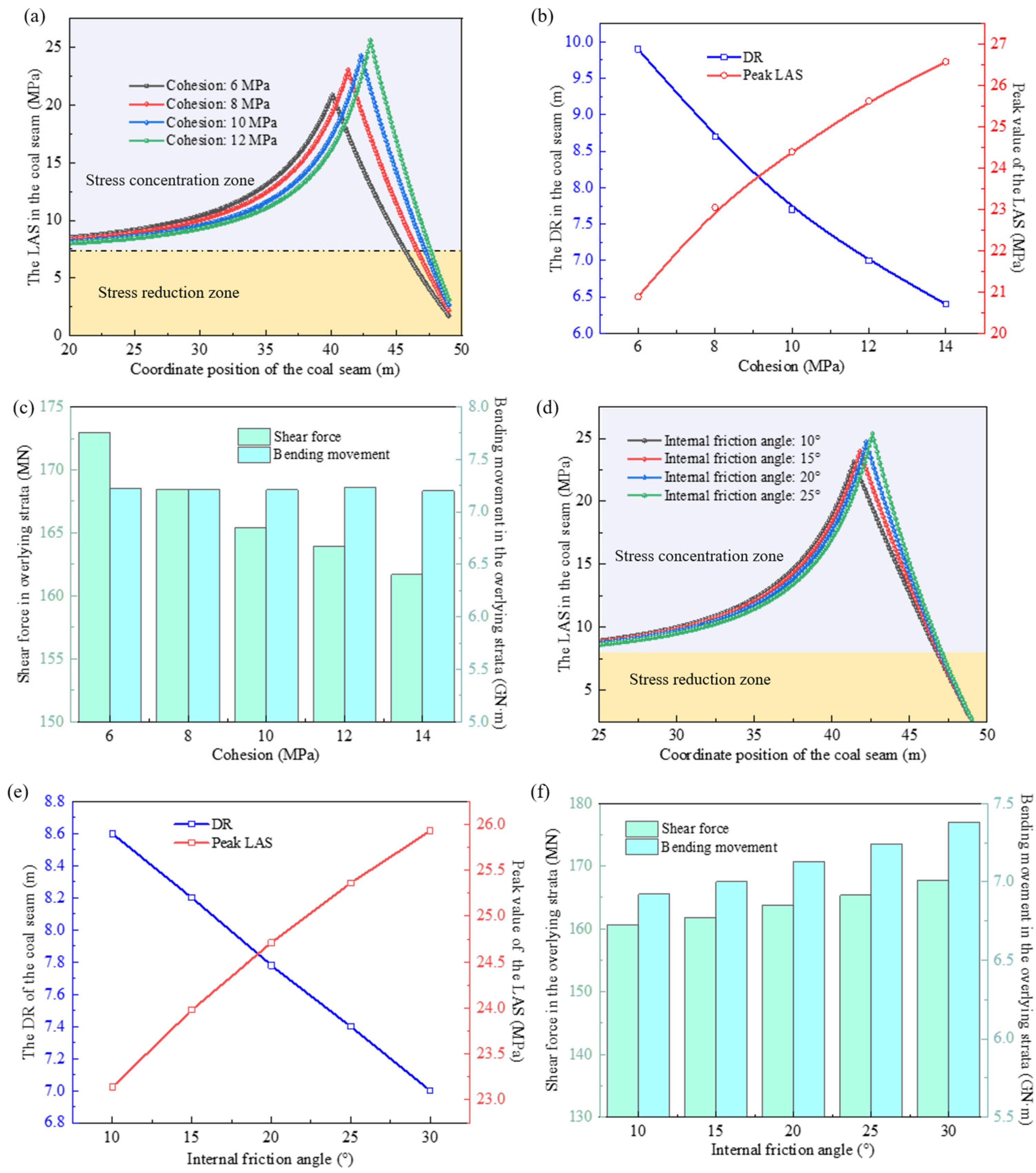
Cohesion and internal friction angle characterize the shear strength of coal. As shown in Figure 11, coal seams with high cohesion and internal friction angle feature a high peak LAS, a narrow stress concentration zone, and a small DR. Cohesion exerts a greater influence on DR and peak LAS than the internal friction angle does. For each 1 MPa increase in cohesion, DR decreases by an average of 0.44 m and peak LAS increases by 0.71 MPa (Figure 11a,b). In contrast, the internal friction angle only causes a change of 0.08 m/° in DR and 0.04 MPa/° in peak LAS (Figure 11d,e).
Figure 11.
Relationship between mechanical properties of coal and its damage range and lateral abutment stress. (a) Lateral abutment stress versus cohesion; (b) Damage range and peak lateral abutment stress versus cohesion; (c) Internal forces of overlying strata versus cohesion; (d) Friction angle versus lateral abutment stress; (e) Internal friction angle and damage range versus peak lateral abutment stress; (f) Friction angle versus internal forces of overlying strata.
Regarding the internal force of the overlying rock strata, an increase in cohesion reduces the shear force while having no effect on the bending moment (Figure 11c). However, both shear force and bending moment increase with the internal friction angle (Figure 11f). That is to say, mining hard coal with high shear strength is prone to cause bending and fracture of the overlying rock in the deep zone of the coal seam. Therefore, hydraulic or blasting degradation of hard and brittle coal to reduce its cohesion and internal friction angle is widely used in engineering practices such as rock burst prevention and high abutment stress transfer [41,42].
3.2.3. Fracture Height of the Overlying Rock Strata
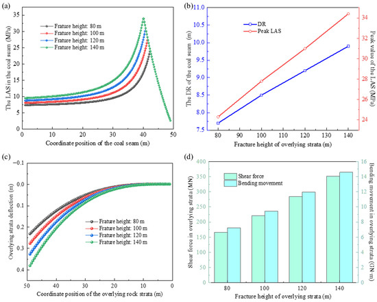
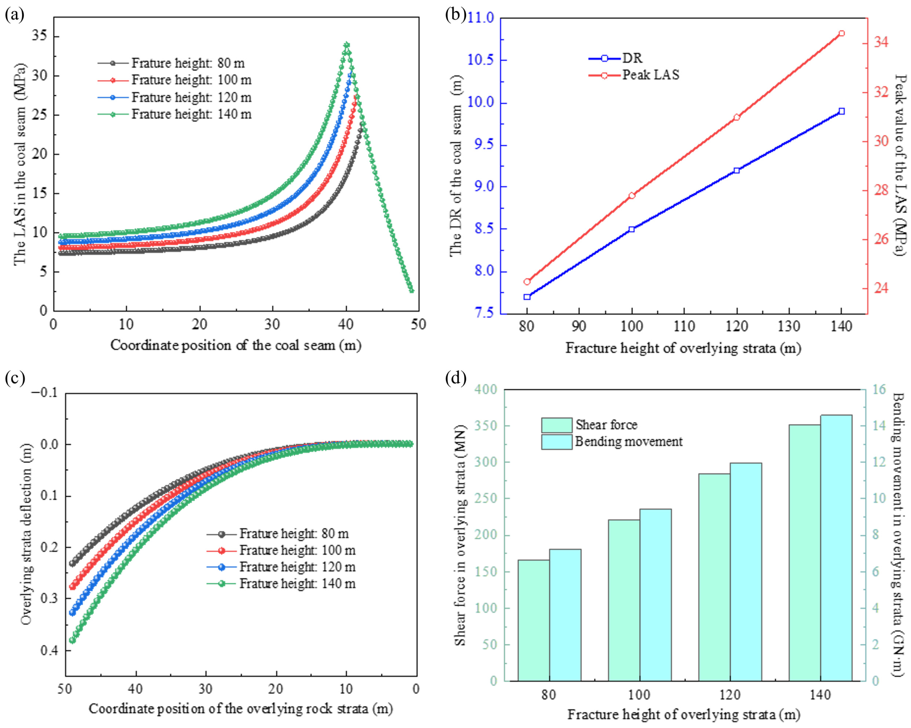
Based on the results in Figure 12a,b, both the DR and peak LAS increase linearly with the fracture height of the overlying strata, with a significant influence effect. Specifically, for every 10 m increase in the overlying strata’s fracture height, the DR expands by 0.35 m and the peak LAS rises by 1.75 MPa. Meanwhile, the internal forces (shear force and bending moment) also increase with the increase in fracture height.
Figure 12.
Relationship between fracture height of overlying strata and its damage range and lateral abutment stress. (a) Influence on lateral abutment stress; (b) Influence on damage range and peak lateral abutment stress; (c) Influence on deflection of overlying strata; (d) Influence on internal forces of overlying strata.
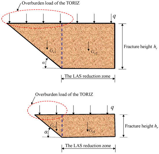
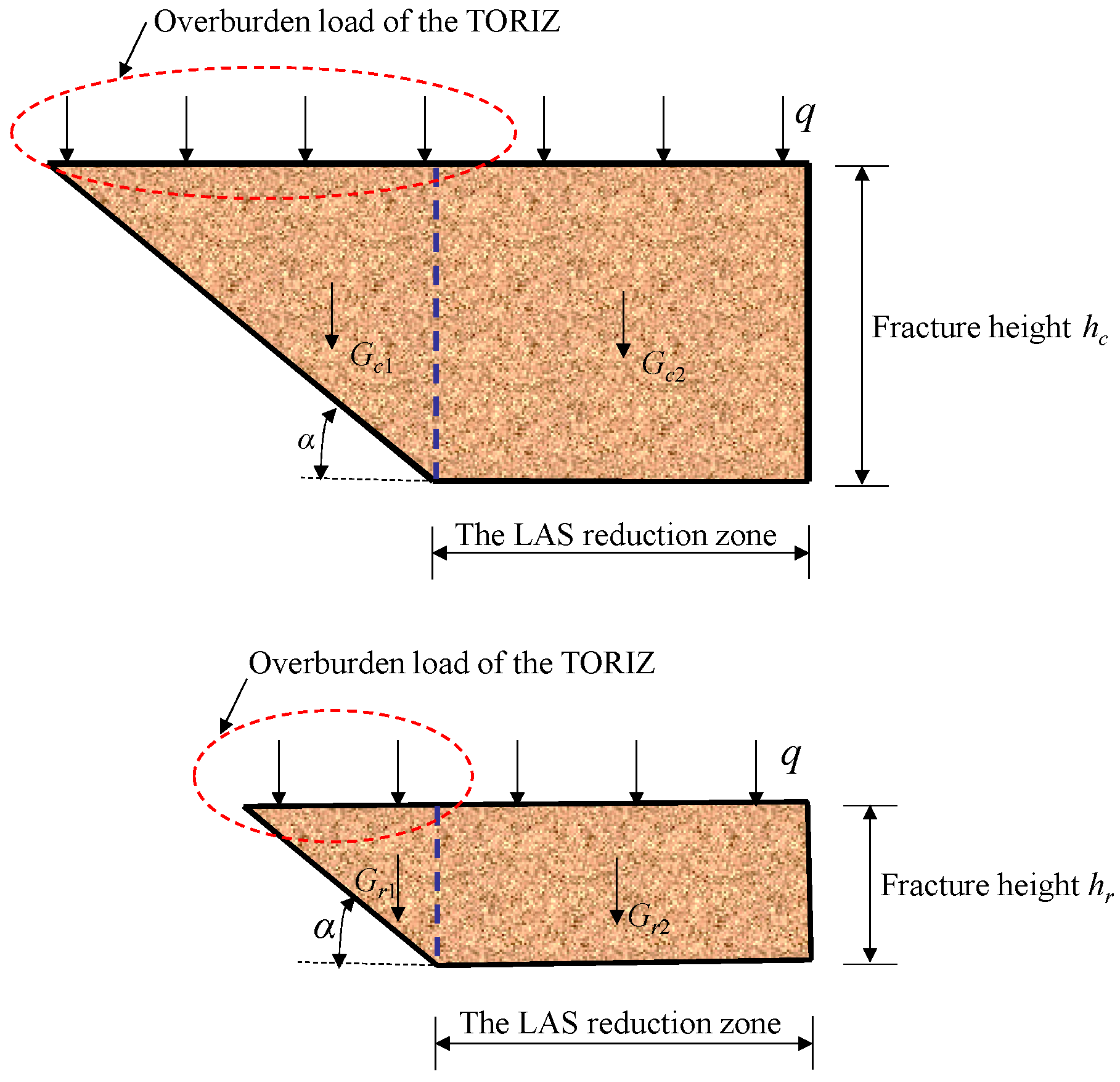
This is because, for the same fracture angle of the overlying strata, an increased fracture height leads to a rise in both the self-weight Gc1 of the overlying strata in the TORIZ (without underlying coal support) and the self-weight Gc2 of the overlying strata in areas where the coal seam LAS is lower than the in situ stress, as well as an increase in the overburden load acting on the TORIZ (Figure 13). The superimposed effect of these three factors causes greater bending deformation of the overlying strata (Figure 12c) and increased compressive deformation of the underlying coal seam. This, in turn, results in the expansion of the DR and a rise in the LAS peak value.
Figure 13.
Structural characteristics of overlying strata on the gob-side under different fracture and caving heights.
3.2.4. Fracture Angle of Overlying Strata
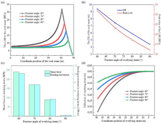
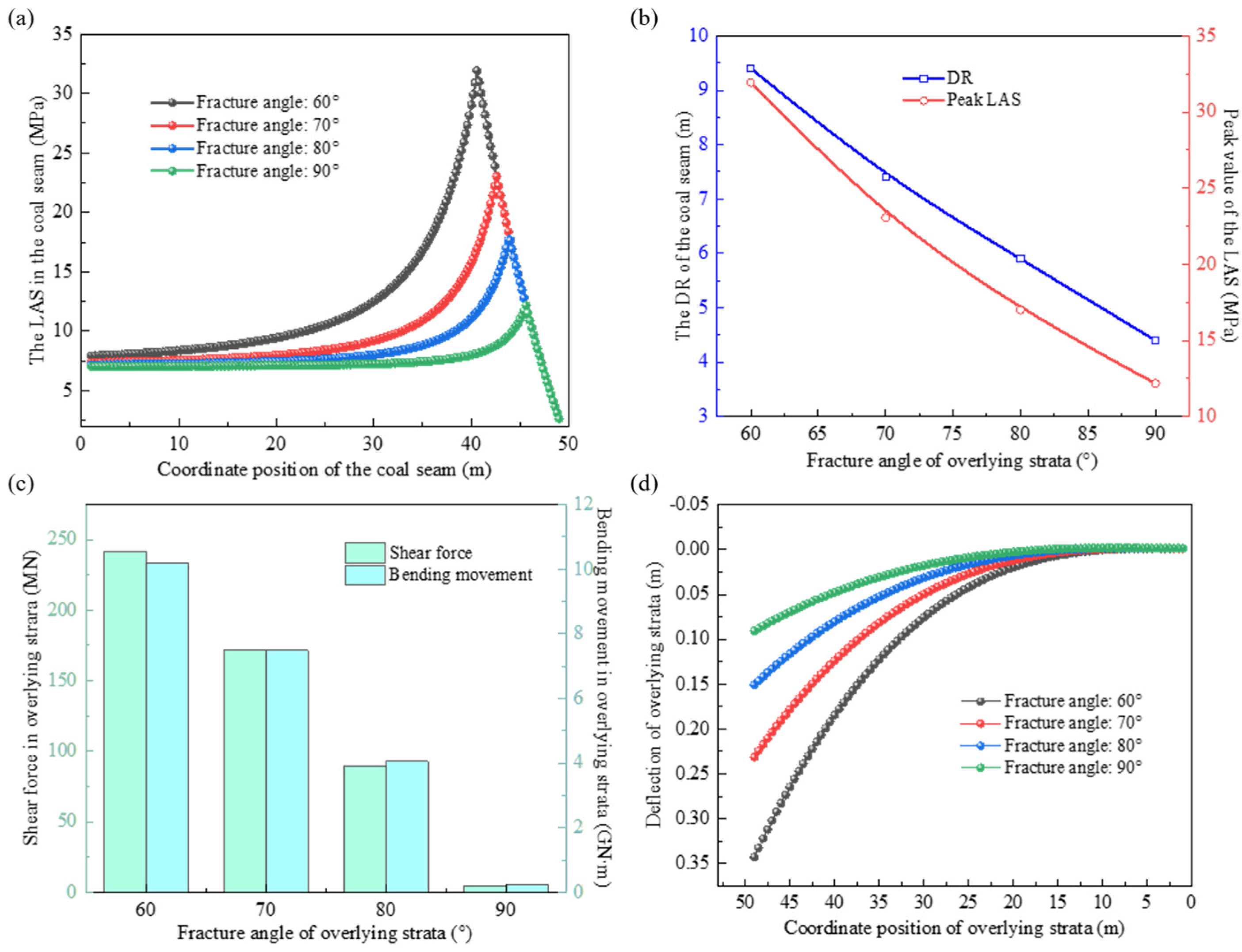
In Figure 14, compared to the fracture angle 90°, the fracture angle 60° results in a 5 m larger DR, a 19.76 MPa higher peak stress, a 0.195 m greater deflection of the overlying strata at x = 45 m, and increases of 237.13 MN in shear force and 9.956 GN·m in bending moment at the O cross-section of the overlying strata. The fracture angle of the overlying strata significantly influences the LAS, and the mechanism is illustrated in Figure 15.
Figure 14.
Relationship between fracture angle and damage range and lateral abutment stress. (a) Influence on lateral abutment stress; (b) Influence on damage range and peak lateral abutment stress; (c) Influence on internal forces in overlying strata; (d) Influence on deflection.
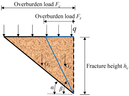
Figure 15.
Structural characteristics of overlying strata under different overlying strata fracture angles.
When the fracture angle α < β, the weight of the overlying strata in the TORIZ Gc > Gr, and the overburden load Fc > Fr. Therefore, under conditions of a smaller fracture angle, both the weight of the overlying strata and the overburden load are greater, leading to a larger DR and a higher peak LAS. The fracture angle is determined by the properties of the rock strata and the boundary conditions. However, in engineering practice, techniques such as pre-splitting or roof cutting can be actively employed to alter the fracture angle of the overlying strata [43,44,45]. This effectively reduces the impact of the overburden load on coal damage and compressive deformation, thereby creating favorable conditions for controlling the surrounding rock of GSEs [46].
3.2.5. Burial Depth of Coal Seam
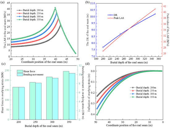
In Figure 16a,b, the coal seam burial depth is proportional to both the peak LAS and the damage depth. At a burial depth of 200 m, the DR and peak LAS are 7.7 m and 26.84 MPa, respectively, while at a burial depth of 350 m, these values increase to 10.2 m and 41.11 MPa, indicating a significant expansion in both the DR and the peak LAS. Furthermore, the increase in burial depth not only raises the load on the coal seam but also amplifies the deflection of the overlying strata and their internal forces, as shown in Figure 16c,d.
Figure 16.
Relationship between burial depth and the damage range and lateral abutment stress. (a) Influence on LAS; (b) Influence on DR and peak LAS; (c) Influence on internal forces in overlying strata; (d) Influence on overlying strata deflection.
4. Formation Mechanism of Lateral Abutment Stress and Model Applicability
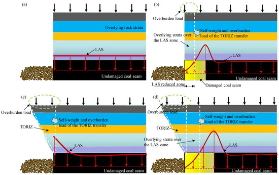
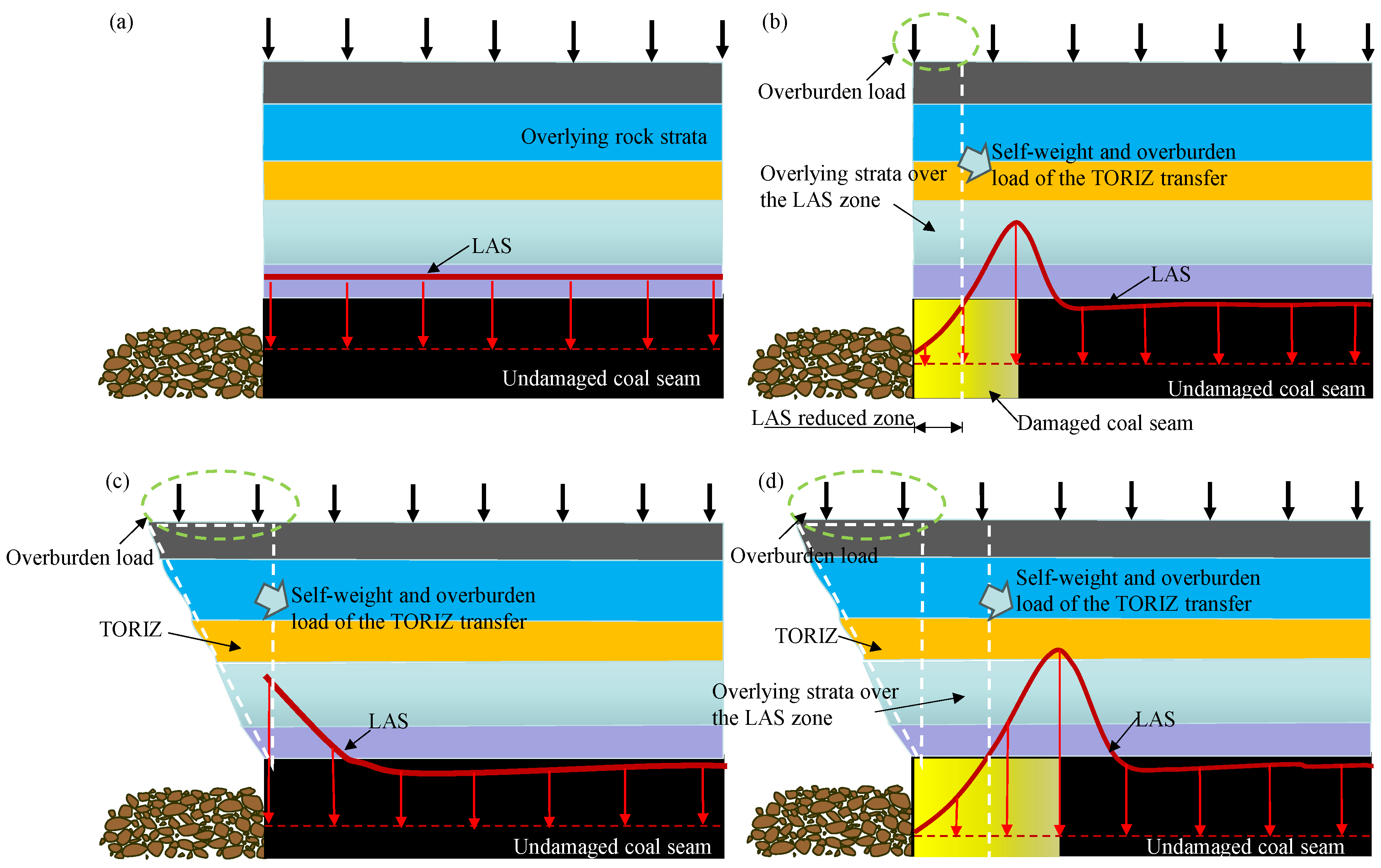
Based on the above research, to reveal the formation mechanism of LAS in the coal seam, four idealized occurrence conditions of the coal seam and overlying strata, as shown in Figure 17, were established. For the coal-rock occurrence condition where the coal seam is undamaged and the fracture angle of the overlying strata is 90° (Figure 17a), the LAS in the coal seam is unaffected by factors such as the reduced load-bearing capacity of weakened coal or load transfer from TORIZ. Consequently, the magnitude of the LAS remains consistent across different zones. However, if damaged coal exists on the gob-side, the self-weight of the overlying strata above this damaged zone (where the LAS is lower than the in situ rock stress) and its associated load will transfer to the deeper, intact coal seam. This results in the formation of an elevated LAS zone within the deeper coal, as illustrated in Figure 17b.
Figure 17.
Characteristics of lateral abutment stress under ideal conditions. (a) Overlying strata fracture angle of 90° with undamaged coal seam; (b) Overlying strata fracture angle of 90° with damaged coal seam; (c) Overlying strata fracture angle less than 90 degrees with undamaged coal seam; (d) Overlying strata fracture angle less than 90° with damaged coal seam.
For the case where the coal seam is undamaged but there is a TORIZ in the overlying strata, the weight and overburden load of the overlying strata in the TORIZ have no support from the underlying coal-rock seam, so they transfer to the deep area of the coal seam, raising the LAS in the deep coal seam, as shown in Figure 17c.
For the case where the coal seam is damaged and there is a TORIZ in the overlying strata (Figure 17d), the weight and overburden load of the overlying strata in the TORIZ and LAS reduction zone migrate to the deep zone of the coal seam when the underlying coal is difficult to support, resulting in an increase in the LAS of local deep coal seam.
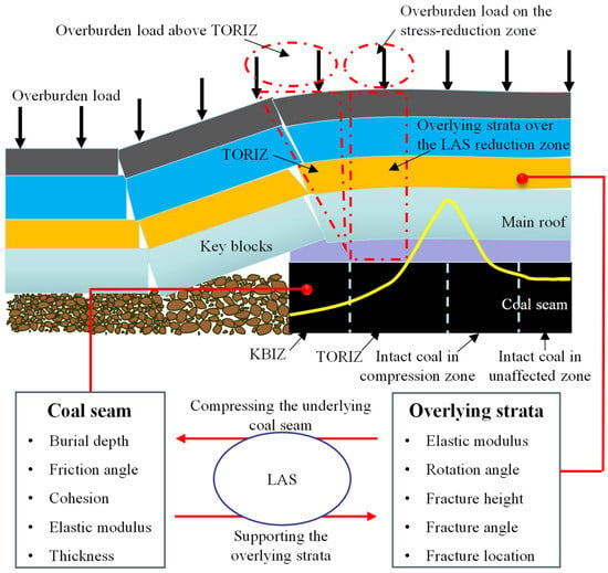
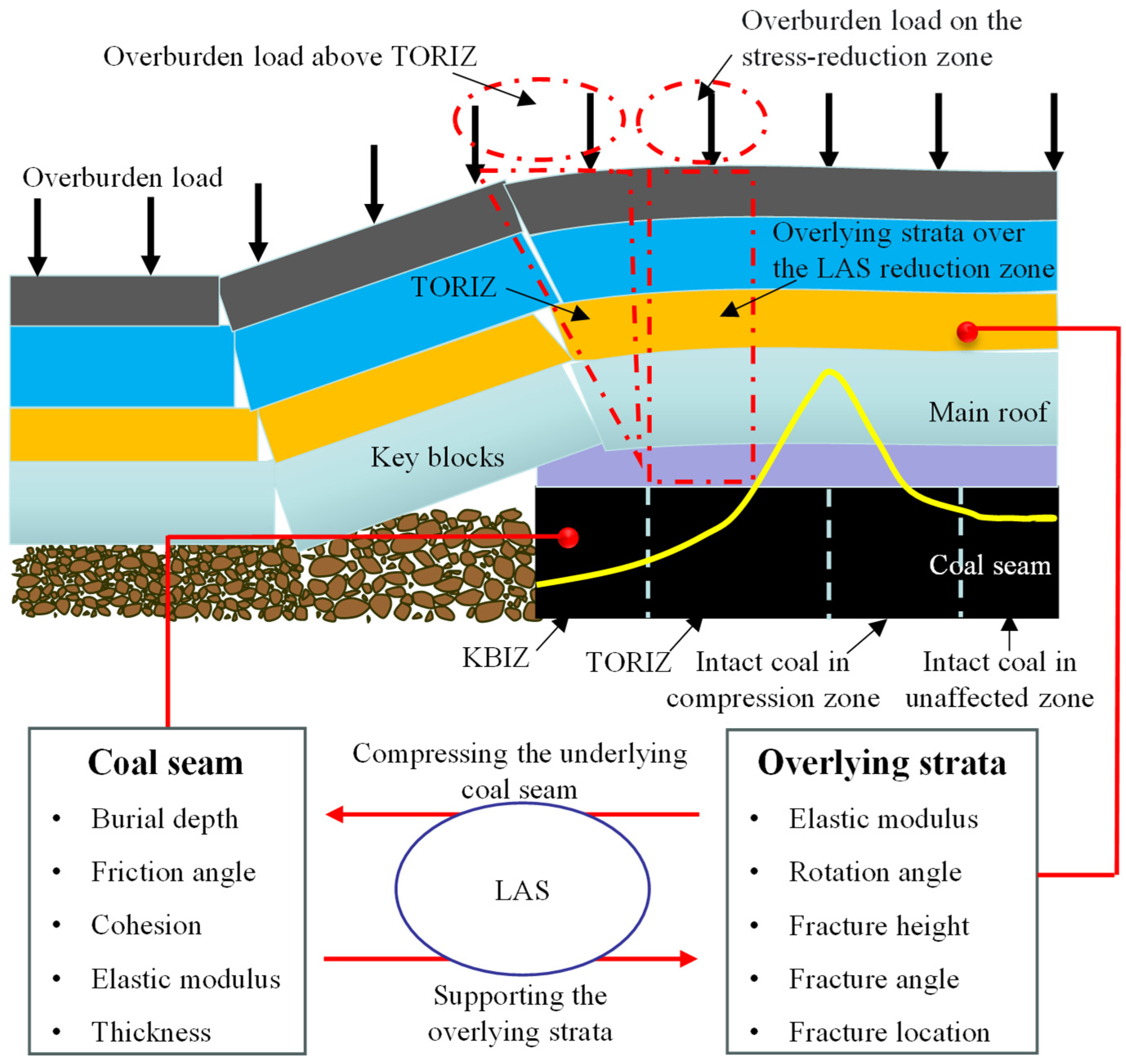
Based on the comprehensive analysis above, it can be concluded that the formation and evolution of LAS in the coal seam result from the interactive effects of multiple factors in the coal-rock system. For the actual coal-rock occurrence structure illustrated in Figure 18, the formation mechanism of the LAS can be described as follows:
Figure 18.
Schematic diagram of lateral abutment stress formation mechanism.
The coal seam beneath the key blocks formed by main roof fracturing sustains severe damage and significant strength degradation. This is caused by the combined effects of upper panel entry development, panel mining, and the fracturing and rotational subsidence of overlying key blocks. The load-bearing capacity of the coal in this area is reduced to its post-peak damaged strength. Typically, the self-weight of the overlying key block and the superimposed overburden load exceed damaged coal residual capacity. The unsupported portion transfers to and balances by the gob gangue. Consequently, the LAS in the KBIZ is governed solely by the coal’s own mechanical properties and damage-induced degradation extent. The magnitude of key block rotational subsidence, in turn, influences the failure severity of the underlying coal seam.
The LAS characteristics of the TORIZ are jointly determined by the overlying strata structure and the coal seam properties. Specifically, the self-weight and the overburden load of the overlying strata in the TORIZ act as the initial trigger for the DR and LAS evolution. More precisely, after upper panel mining, the overlying strata fracture and cave at a certain fracture angle, forming a TORIZ. The self-weight of the overlying strata in this area and the overburden load, due to the lack of support from the underlying coal and rock, can only be borne by the deeper overlying strata. This leads to increased deflection of the overlying strata and consequently compresses the underlying coal seam.
Meanwhile, the underlying coal seam bears partial load from the overlying strata in the TORIZ, leading to an increase in LAS. When the compression from the overlying strata exceeds the bearing capacity of the coal seam, damage occurs. At this point, the LAS is governed by its post-damage mechanical properties. When the extent of damage is significant, the supporting capacity of the coal seam to the overlying strata falls below the in situ stress level prior to damage. In the LAS reduction zone, the unsupported portion of the overlying strata’s self-weight and load is transferred to the deeper overlying strata and coal seam. Consequently, coal mass damage develops progressively from the shallow to the deep zone. The interface between the damaged and intact coal zones exists in a critical state of failure. Once the compression imposed by the overlying strata increases, the coal at this location becomes damaged, and the peak LAS advances further into the coal seam. Through the processes of overlying strata bending and subsidence, coupled with coal compression and failure evolution, the support provided by the coal mass to the overlying strata and its load eventually reaches a state of static equilibrium, ultimately forming a stable LAS.
This mechanical model comprehensively takes into account thickness and burial depth, mechanical properties of the coal seam, fracture characteristics of the overlying strata, as well as the occurrence characteristics of key blocks, as illustrated in Figure 19. Therefore, the model has the following specific application scopes:
Figure 19.
Applicability of the mechanical model.
- (a)
- This mechanical model fully accounts for the influence of coal seam thickness h1 on LAS and DR, and an in-depth investigation on this aspect is conducted in Section 3.2.1. Therefore, this model is applicable to thin coal seams (h1 ≤ 1.3 m), medium-thickness coal seams (1.3 m < h1 ≤3.5 m), thick coal seams (3.5 m < h1 ≤ 8 m), and extra-thick coal seams (8 m < h1).
- (b)
- Based on the internal friction angle φ0 and cohesion c0, this model can analyze the LAS and DR of coal masses with different strengths. In addition, it can provide quantitative guidance for the softening of hard coal, reduce the LAS of coal seams, and prevent dynamic disasters such as rock bursts.
- (c)
- Through the in situ stress of the coal seam σd, this model can realize quantitative analysis of LAS and DR under different coal seam burial depths.
- (d)
- This model takes into account the position l of the overlying strata fracture line, enabling systematic investigation of LAS and DR under different fracture positions.
- (e)
- This model uses parameters h2 and α to characterize the different fracture heights and angles of overlying strata. Thus, it is capable of analyzing the LAS and DR under different overlying strata fracture characteristics.
- (f)
- This model can analyze the LAS and DR of coal seams under different rotation angle β and subsidence amount hc1 of key blocks.
The mechanical model does not take into account the occurrence angle of the coal seam and multi-seam mining conditions. Therefore, the model is not applicable to the analysis of LAS and DR in inclined coal seams or under multi-seam mining conditions. Moreover, mining-induced stress affects LAS and DR during panel extraction [47,48]. This aspect could be addressed in the future.
5. Engineering Applications
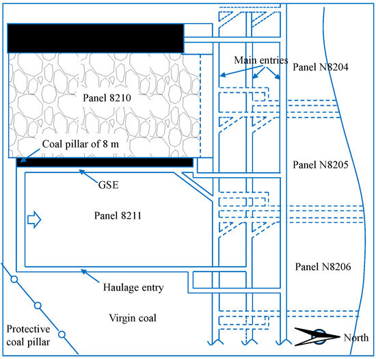
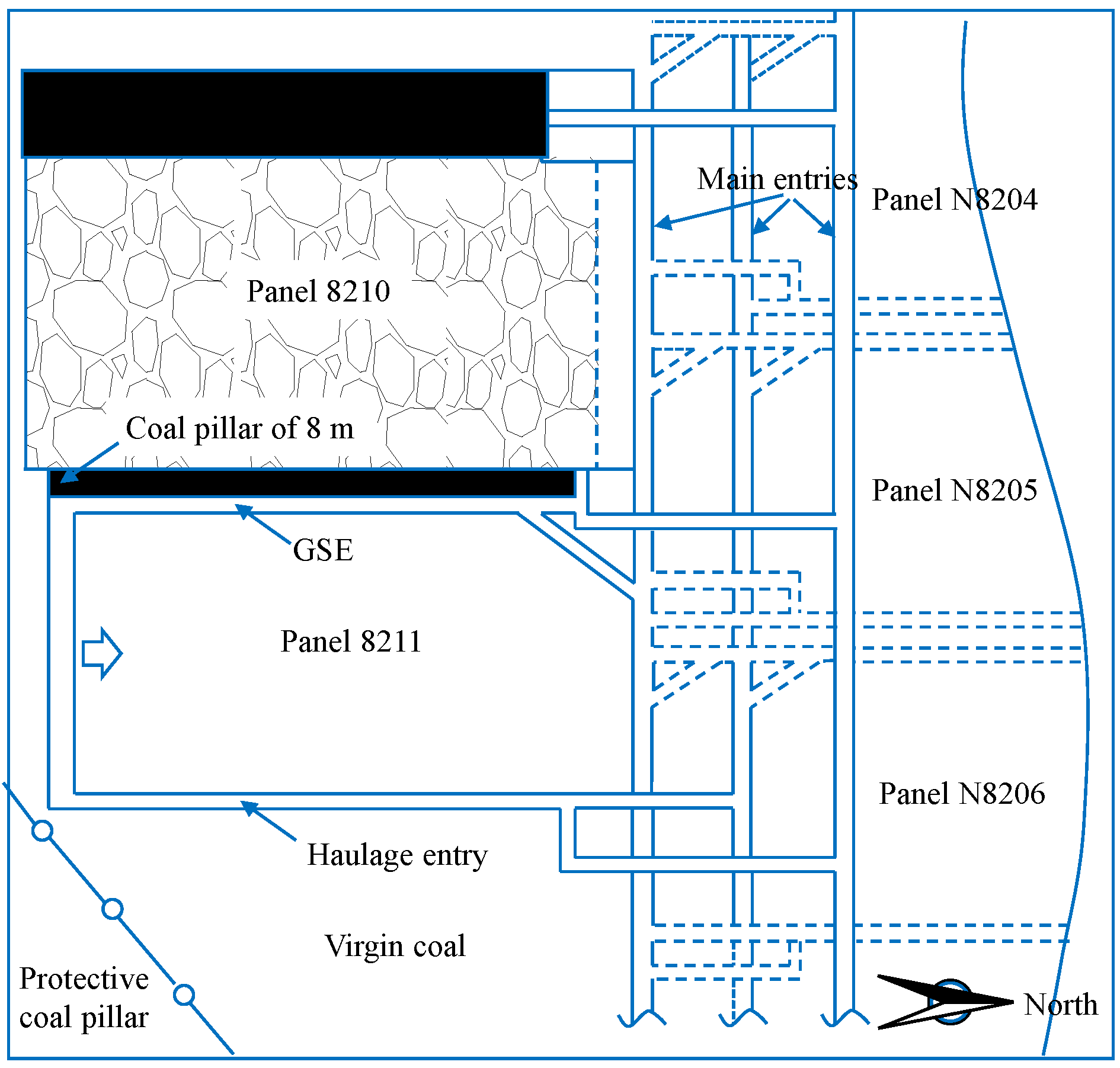
Panel 8211 of the longwall face in Madaotou Coal Mine is situated at the easternmost part of the No. 2 North panel district. To its west lies the fully mined and stabilized Panel 8210; to its east is virgin coal under a village protective coal pillar; to its north are the planned but unmined Panels N8206 and N8205 (Figure 20). This panel has a burial depth of 415 m and an average coal seam thickness of 15.1 m, being an extra-thick and nearly horizontal coal seam mined by fully mechanized top-coal caving. Laboratory test results show the coal has an internal friction angle of 14° and cohesion of 0.33 MPa, with compressive moduli of 2.26 GPa (intact) and 30 MPa (damaged), respectively. The lateral resistance of the coal rib is 0.5 MPa. The main roof above the coal seam is medium-coarse sandstone with an average thickness of 14.7 m, dipping toward the virgin coal at a depth of approximately 15.2 m. The key stratum blocks have a rotation angle of 15°. The fractured and collapsed height of overlying strata in the goaf is 86.3 m, with a fracture angle of 85°. The elastic modulus of the rock strata is 46.5 GPa.
Figure 20.
Location of the Panel 8211.
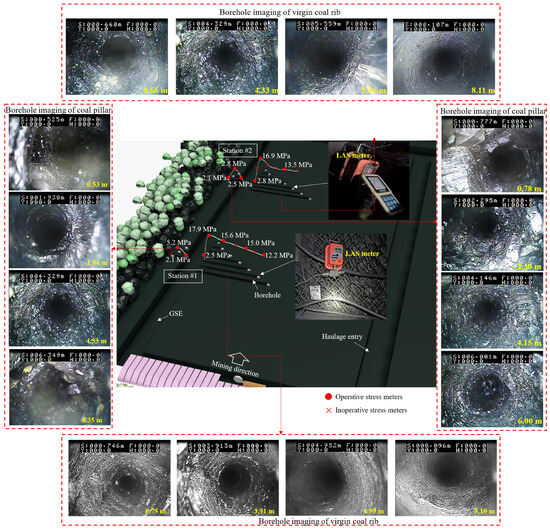
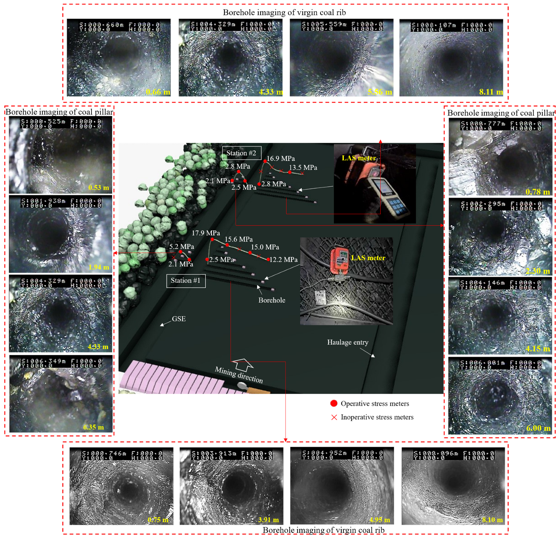
Two monitoring stations (#1 and #2) were arranged in the GSE with the 8 m coal pillar of the panel 8211, with an interval of 15 m between the two stations. Ten monitoring boreholes of LAS, spaced at 2 m intervals, were installed at each station. Specifically, three boreholes were arranged on the 8 m coal pillar, with monitoring depths of 2 m, 4 m and 6 m respectively; seven boreholes were deployed on the virgin coal rib, with depths of 1 m, 6 m, 11 m, 16 m, 21 m, 26 m and 31 m respectively. All boreholes had a diameter of 42 mm. A borehole stress meter was placed in each borehole and pushed to the bottom of the borehole, and an initial stress of 2 MPa was applied to ensure its close contact with the borehole wall. Additionally, the boreholes used for installing stress meters were also utilized to observe the failure characteristics of the coal on both the coal pillar and virgin coal rib by borehole television (CXK7.2(A)-Z, Huakuang Design and Research Institute, Shandong, China).
The test results of LAS and DR of the coal seam are presented in Figure 21. Since some stress meters at the two monitoring stations malfunctioned, the LAS was comprehensively analyzed based on the stress data from both stations.
Figure 21.
Field monitoring of lateral abutment stress and damage range in coal seam.
The average peak value of LAS in the virgin coal rib was 17.4 MPa, and the DR of the coal seam was approximately 4.12 m. The peak LAS in the coal pillar rib was 4.0 MPa, indicating that the 8 m coal pillar underwent overall failure.
The DR can be determined by the sum of the width of the coal pillar, the width of the 6 m-wide GSE, and the damage depth of the virgin coal rib. It can be concluded that the peak value of LAS was 17.4 MPa, and the DR was 18.12 m.
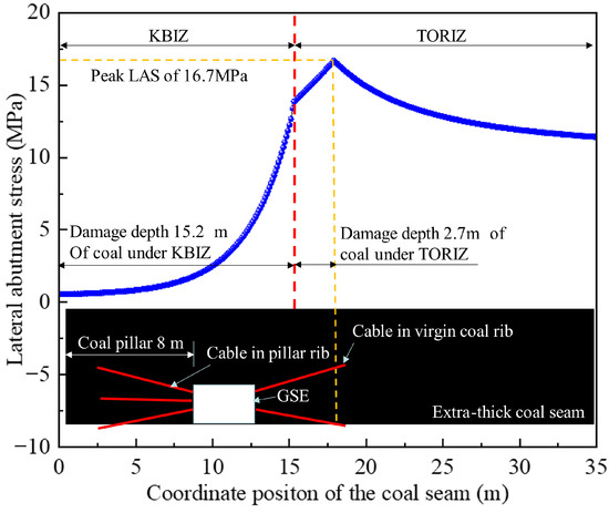
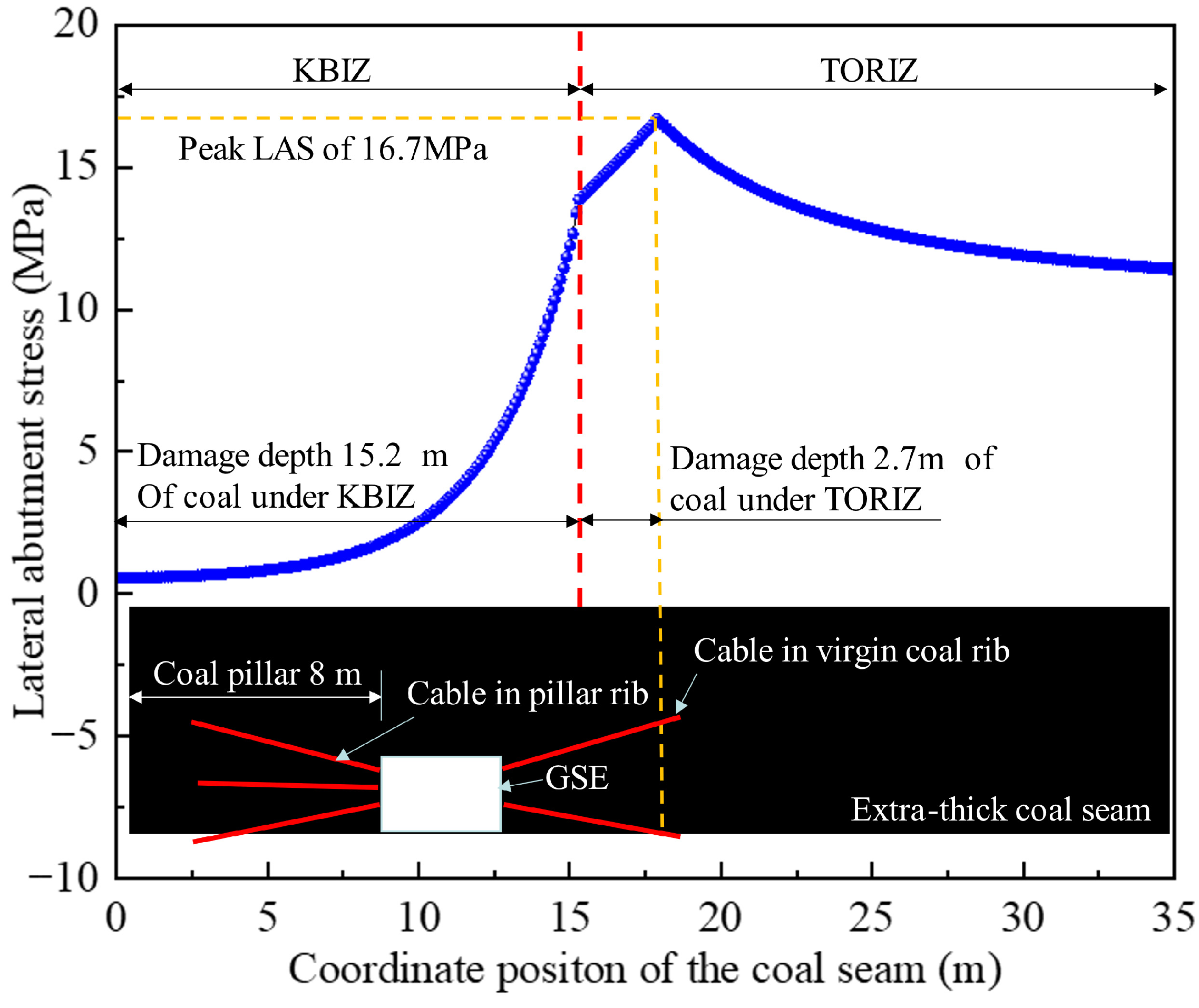
Based on the engineering and geological conditions of the 8211 panel, the mechanical analysis model was applied to investigate the distribution principle of the DR and LAS. The aim is to provide guidance for determining the optimal location of the GSE and designing the surrounding rock control scheme. The calculation results are shown in Figure 22. The peak LAS in the coal seam is 16.7 MPa, and the extent of coal mass damage is 17.9 m. These results show a deviation of 6.7% from the field-measured peak LAS of 17.9 MPa reported in the study [49], and a deviation of 1.2% from the observed DR of 18.12 m obtained via borehole imaging. This close agreement further validates the reliability of the proposed mechanical model.
Figure 22.
The DR and LAS of Panel 8211.
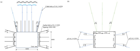
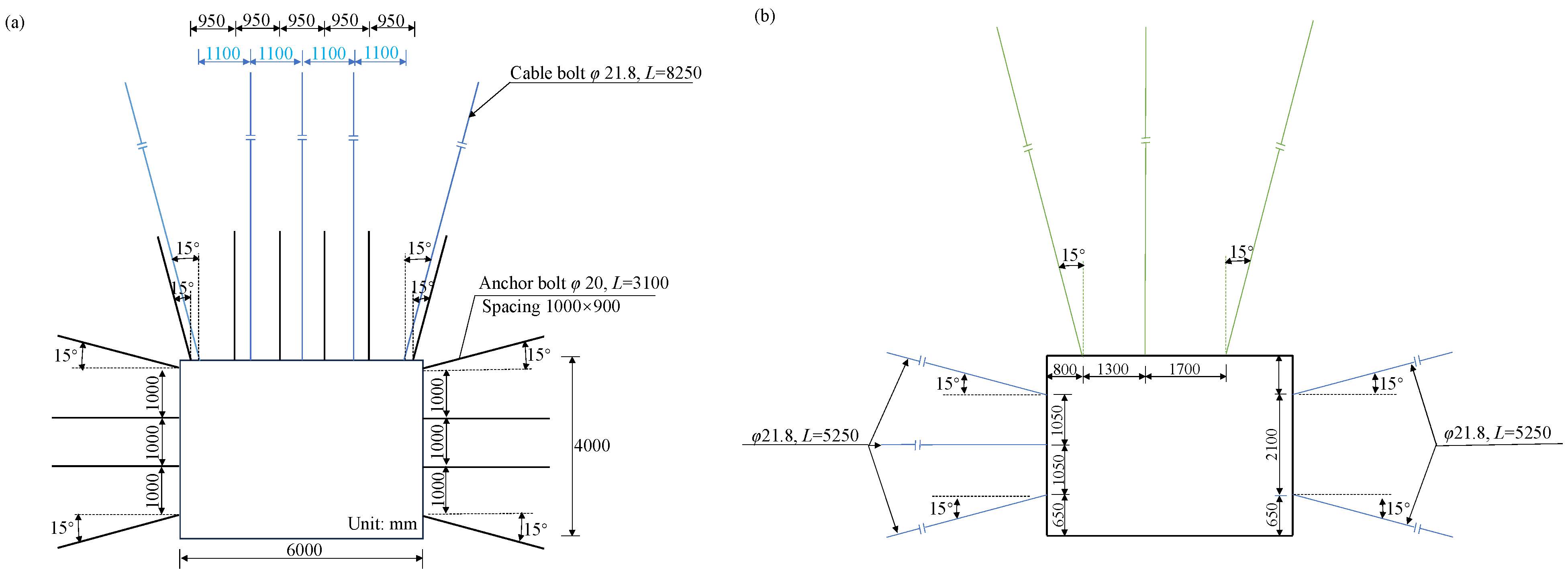
Based on the aforementioned research findings, an 8 m coal pillar was designed for the GSE of the 8211 panel. This configuration places the GSE in a low-stress environment, thereby creating favorable conditions for controlling surrounding rock stability. Furthermore, based on the determined coal failure range, the damage depth on the virgin coal rib was identified as 4.7 m. Consequently, 5.25 m long cables were employed on the virgin coal rib to anchor the plastic zone into the elastic zone. The specific support design is illustrated in Figure 23.
Figure 23.
Support Scheme for the GSE. (a) Cross-sectional view of roof support with “single beam + five bolts” configuration; (b) Cross-sectional view of roof support with “single beam + three bolts” configuration.
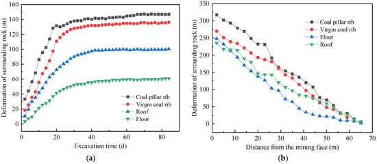
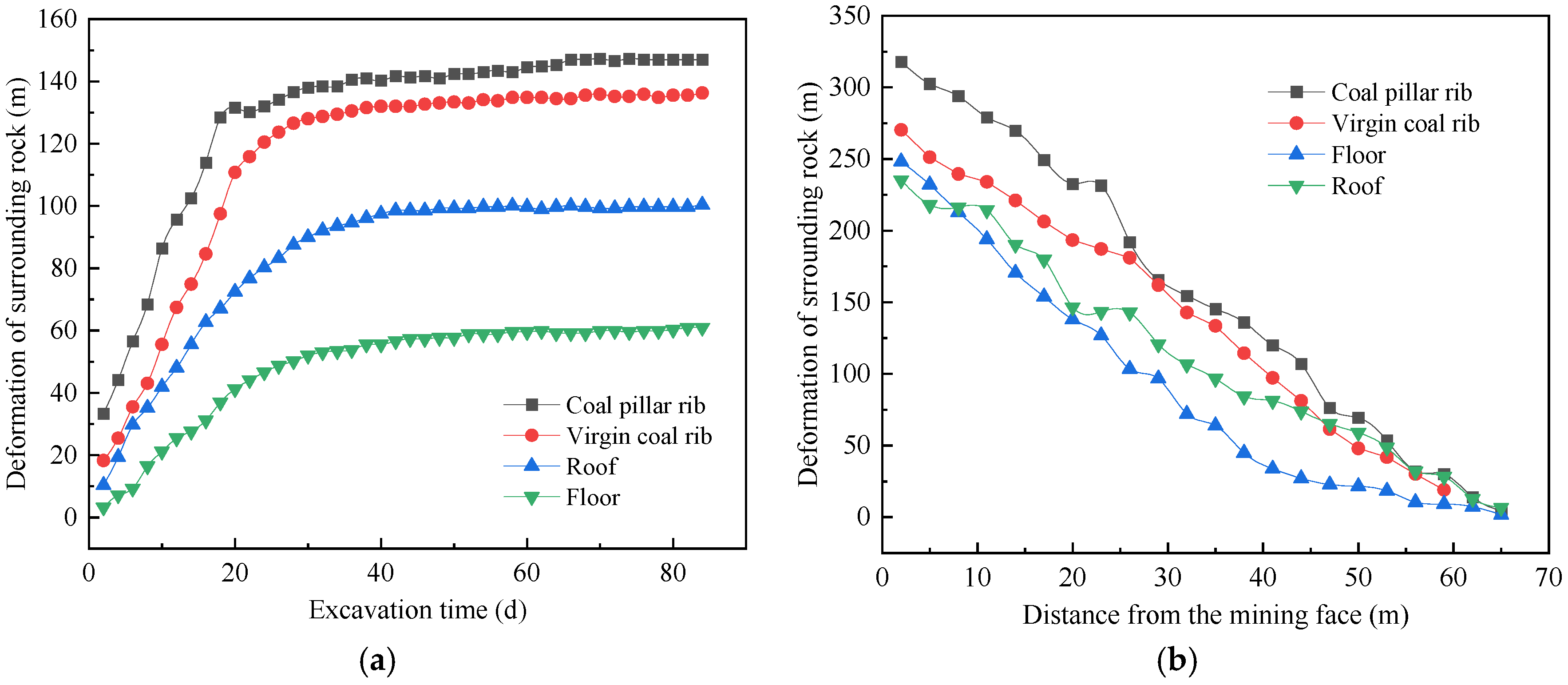
Following the implementation of this GSE layout and surrounding rock control strategy, the maximum convergence observed in the GSE of panel 8211 was 295 mm (roof-to-floor) and 158 mm (rib-to-rib) during the development stage, and 591 mm (roof-to-floor) and 479 mm (rib-to-rib) during the mining stage, as shown in Figure 24. The overall condition of the GSE remained good, with controlled deformation and failure of the surrounding rock, successfully meeting the requirements for ventilation, personnel passage, production, and safety.
Figure 24.
Monitoring of surrounding rock deformation in GSE. (a) Excavation stage; (b) Mining stage.
6. Conclusions
This study establishes a coupled mechanical model for analyzing the lateral abutment stress and damage range of coal seams. The model comprehensively considers the mechanical properties, thickness and burial depth of the coal seam, as well as the fracture characteristics of overlying strata. It yields analytical results comparable to those of numerical simulations. However, the model only applies to static ground pressure conditions and does not account for the coal seam dip angle. Future research can extend the model’s analytical method to develop models for inclined coal seams, multi-seam mining scenarios, and mining conditions under the influence of mining-induced dynamic loads.
In the key block influenced zone, the lateral abutment stress is governed by the failure and mechanical behavior of the coal itself. In the overhanging roof influenced zone, the lateral abutment stress is initially influenced by the weight of the overhanging roof and its overburden load. In the later stage, it is co-influenced by the weight in both the triangular overhanging roof influence zone and the reduction zone of the lateral abutment stress. The greater the degree of strength degradation of the coal caused by the subsidence and rotation of key blocks, the lower the lateral abutment stress in the key-block-influenced zone. The overlying strata in the overhanging roof affect the lateral abutment stress and damage range through deflection deformation; the larger the deformation of the unbroken overlying strata with self-bearing capacity, the higher the load they share.
Coal seam thickness and overlying strata fracture angle show a positive correlation with the peak lateral abutment stress. However, for extra-thick coal seams, the sensitivity of the peak lateral abutment stress to coal seam thickness decreases. The cohesion and internal friction angle of the coal are proportional to the peak lateral abutment stress but inversely proportional to the damage range. In contrast, the fracture height of the overlying strata and the burial depth of the coal seam exhibit positive correlations with both the peak lateral abutment stress and damage range.
Author Contributions
Conceptualization, W.H. and D.C.; methodology, W.H.; software, W.H.; validation, W.H., D.C. and H.Z.; formal analysis, W.H.; investigation, W.H.; resources, W.H.; data curation, W.H.; writing—original draft preparation, W.H.; writing—review and editing, H.Z.; visualization, W.H.; supervision, H.Z.; project administration, H.Z.; funding acquisition, W.H. All authors have read and agreed to the published version of the manuscript.
Funding
This research was funded by Natural Science Foundation of Zhejiang Province (Grant No. LQN26E040007), China Postdoctoral Science Foundation (Grant No. 2024M763553), Scientific Research Fund of Zhejiang Provincial Education Department (Grant No. Y202352229), Housing and Urban-Rural Development Department of Zhejiang (Grant No. 2024K374), and Youth Project of Jiaxing Science and Technology Program (Grant No. 2024AY40014).
Data Availability Statement
The original contributions presented in this study are included in the article, further inquiries can be directed to the corresponding authors.
Conflicts of Interest
The authors declare no conflicts of interest.
Abbreviations
| LAS | Lateral abutment stress | qm1 | Lateral abutment stress in the damage zone coal mass under overhanging roof influence zone |
| DR | Damage range | qm2 | Lateral abutment stress in the coal mass of the elastic zone |
| TORIZ | Triangular overhanging roof influenced zone | c0 | Cohesion and of the coal mass |
| KBIZ | Key block influenced zone | φ0 | Internal friction angle of the coal mass |
| GSE | Gob-side entry | Pz | Lateral support resistance of the coal rib |
| l | Influenced range of the overhanging roof influence zone | As | Lateral pressure coefficient |
| h2 | Height of the fractured overlying strata | σd | In situ stress of the coal seam |
| T | stress correction coefficient | r1 | Radius of the hole |
| γ | average bulk density of the overlying rock | b | Damage range of the coal seam |
| g1 | Strata weight of the overhanging roof influence zone | α | Fracture angle of the overlying strata |
| F | Internal shear force in the overlying strata | l1 | Length of the overlying strata at the top |
| Mq | Bending moment in the overlying strata due to the overburden load q | q | Overburden load on the overlying strata |
| Mqm1, Mqm2 | Bending moment in the overlying strata due to the abutment stress qm1 and qm2, respectively | Mg1, Mg2 | Bending moment in the overlying strata due to the overhanging roof weight g1 and non-overhanging roof weight g2, respectively |
| M | Bending moment in the overlying strata | wg1, wg2 | Deflection due to the overhanging roof weight g1 and g2, respectively |
| w qm1, w qm2 | Deflection due to the abutment stresses g1 and g2, respectively | Em1 | Compression modulus of the elastic coal mass |
| E | Elastic modulus of the overlying strata | Em2 | Compression modulus of the damaged coal mass |
| h3 | Load-bearing layer thickness of the fractured overlying strata | wq | Deflection due to the overburden load q |
| σ1, σ3 | Normal and confining stresses of the coal seam | m | Scale parameter of Weibull damage distribution |
| I | Inertia moment of the overlying strata | ε0 | Shape parameter of Weibull damage distribution |
| ε1 | Strain of the coal mass | hc1 | Compression of the coal mass induced by the overlying strata |
| β | Rotation angle of the key block | d | Distance from the main roof fracture line to the coal rib |
| hc | Total compression of the coal seam due to the key block |
References
- Wang, X.; Xia, Z.; Yao, Q.; Li, X.; Xu, Q.; Zhu, L. Numerical investigation of coal pillar damage mechanisms for various width-to-height ratios. Sci. Rep. 2025, 15, 2705–2720. [Google Scholar] [CrossRef] [Scilit]
- Zhang, Z.; Li, Z.; Xu, G.; Liu, Q.; Li, Z.; Liu, J. Lateral abutment pressure distribution and evolution in wide pillars under the first mining effect. Int. J. Min. Sci. Technol. 2023, 33, 309–322. [Google Scholar] [CrossRef] [Scilit]
- Zhuang, J.; Mu, Z.; Cai, W.; He, H.; Hosking, L.J.; Jiao, B. Multistage hydraulic fracturing of a horizontal well for hard roof related coal burst control: Insights from numerical modelling to field application. Int. J. Min. Sci. Technol. 2024, 34, 1095–1114. [Google Scholar] [CrossRef] [Scilit]
- Kang, Y.; Geng, Z.; Liu, B.; Chen, J. Investigation of the evolution characteristic of abutment pressure during the longwall retreat mining process: A case study using field tests and numerical simulation method. Int. J. Geomech. 2024, 24, 05023011. [Google Scholar] [CrossRef] [Scilit]
- Guo, Y.; Liu, X.; Li, W.; Du, F.; Ma, J.; Qian, R.; Huo, N. Research on abutment stress distribution of roof-cutting coalface: Numerical simulation and field measurement. Geomech. Geophys. Geo-Energy Geo-Resour. 2024, 10, 86. [Google Scholar] [CrossRef] [Scilit]
- Qin, H.; Cheng, Z.; Ouyang, Z.; Zhao, X.; Feng, J. Relationship between advancing abutment pressure and deformation of surrounding rock in a roadway: A case study in Helin coal mine in China. Environ. Earth Sci. 2021, 80, 763. [Google Scholar] [CrossRef] [Scilit]
- Fu, Z.; Zhang, W. Research on stress change and deformation monitoring of coal pillar between two longwall coal faces. Rock Mech. Rock Eng. 2024, 57, 2763–2772. [Google Scholar] [CrossRef] [Scilit]
- Zhang, L.; Shen, W.; Li, X.; Wang, Y.; Qin, Q.; Lu, X.; Xue, T. Abutment pressure distribution law and support analysis of super large mining height face. Int. J. Environ. Res. Public Health 2023, 20, 227. [Google Scholar] [CrossRef] [Scilit]
- Li, C.; Xie, H.; Gao, M.; Xie, J.; Deng, G.; He, Z. Case study on the mining-induced stress evolution of an extra-thick coal seam under hard roof conditions. Energy Sci. Eng. 2020, 8, 3174–3185. [Google Scholar] [CrossRef] [Scilit]
- Zhang, Z.; Xu, G.; Gao, X.; Huang, Z.; Liu, Q.; Li, Z. Characteristics and mechanism of stope abutment pressure during the whole process. J. Min. Saf. Eng. 2023, 40, 1219–1230. [Google Scholar] [CrossRef]
- Wang, Q.; He, M.; Li, S.; Jiang, Z.; Wang, Y. Comparative study of model tests on automatically formed roadway and gob-side entry driving in deep coal mines. Int. J. Min. Sci. Technol. 2021, 31, 591–601. [Google Scholar] [CrossRef] [Scilit]
- Yang, G.; Yang, X.; Zhang, J.; He, M.; Hao, Z.; Yang, F.; Shao, J. Effect of roof cutting technology on broken roof rock bulking and abutment stress distribution: A physical model test. Rock Mech. Rock Eng. 2024, 57, 3767–3785. [Google Scholar] [CrossRef] [Scilit]
- Zhao, Z.; Ma, Q.; Chen, S.; Ma, H.; Gao, X. Prediction model of failure zone in roadway sidewall considering the lithologic effect of rock formation. Math. Probl. Eng. 2018, 2018, 9627564. [Google Scholar] [CrossRef] [Scilit]
- Wu, H.; Chen, Y.; Lv, H.; Xie, Q.; Chen, Y.; Gu, J. Stability analysis of rib pillars in highwall mining under dynamic and static loads in open-pit coal mine. Int. J. Coal Sci. Technol. 2022, 9, 38. [Google Scholar] [CrossRef] [Scilit]
- Chen, Z.; Xie, H. Damage mechanics analysis on the distribution of abutment pressure around a coal face. Chin. J. Rock Mech. Eng. 2000, 19, 436–439. [Google Scholar]
- Wang, W.; Feng, T.; Hou, C.; Zhang, X. Analysis on the relationship between stress distribution on integrated coal beside roadway driving along next goal and damage of surrounding rocks. Chin. J. Rock Mech. Eng. 2002, 21, 1590–1593. [Google Scholar]
- Xie, G.; Wang, L. Effect of mining thickness on abutment pressure of working face. J. China Coal Soc. 2008, 33, 361–363. [Google Scholar] [CrossRef]
- Xue, D.; Zhou, H.; Peng, R.; Wang, J.; Deng, L.; Zhao, Y. Strong disturbance of discontinuous abutment pressure. Chin. J. Rock Mech. Eng. 2018, 37, 1081–1095. [Google Scholar] [CrossRef]
- Song, Z.; Song, Y.; Liu, Y.; Jiang, J. The Theory of Internal and External Stress Fields and Its Application in Mine Pressure Control. In Proceedings of the Academic Conference on Rock Mechanics and Engineering Applications in Northern China; Mining Pressure Research Institute of Shandong Mining University: Qingdao, China, 1991. [Google Scholar]
- Huo, B.; Meng, F.; Li, T.; Song, Z.; Jing, J. Small coal pillar technology in fully-mechanized top-coal caving face of multi-layer hard roof and extra thick coal seam. Coal Sci. Technol. 2024, 52, 13–23. [Google Scholar] [CrossRef]
- Wang, H.; Tian, C.; Liu, Y.; Li, Y.; Lu, M.; Jiao, J.; Bai, J.; Qiao, Z. Overburden structure fracture evolution and ground pressure behavior under oblique residual coal pillars in thick seam mining. Sci. Rep. 2025, 15, 30932. [Google Scholar] [CrossRef] [Scilit]
- Li, S.; Wei, Q.; Liu, J. Method of determining the reasonable position of open-off cut based on abutment pressure estimation. J. China Coal Soc. 2016, 41, 557–563. [Google Scholar] [CrossRef]
- Liu, J.; Jiang, F.; Zhu, S. Study of dynamic and static abutment pressure around longwall face and its application. Chin. J. Rock Mech. Eng. 2015, 34, 1815–1827. [Google Scholar] [CrossRef]
- Liu, H.; Wang, P.; Liu, Y.; Dai, J.; Yang, J. A new theoretical method for calculating front abutment stress during coal mining. Energy Sci. Eng. 2019, 8, 836–848. [Google Scholar] [CrossRef] [Scilit]
- Jia, Q.; Ji, S.; Zhang, J.; Fang, Z.; Lyu, C.; Jurij, K. The control mechanism of the coal pillar width on the mechanical state of hard roofs. Mathematics 2025, 13, 2548. [Google Scholar] [CrossRef] [Scilit]
- Li, Y.; Chang, G. Evolution and stability mechanics analysis of the elliptical stress arch structure in the surrounding rocks of the underground mining area. Sci. Rep. 2025, 15, 14895. [Google Scholar] [CrossRef] [Scilit]
- Wang, Y. Evolution mechanism of end structure and abutment pressure on fully-mechanized top coal caving face in extra thick coal seam. J. China Coal Soc. 2017, 42, 30–35. [Google Scholar] [CrossRef]
- Chen, D.; Chang, J.; Zou, J.; Tian, C.; Xie, S.; Ni, J.; Guo, F.; Zhang, Z.; Zhao, W.; Yang, X.; et al. Mechanisms of surrounding rock failure and control measures when main roof fractures directly above gob-side entry in thick coal seam. Appl. Sci. 2025, 15, 4284. [Google Scholar] [CrossRef] [Scilit]
- Guo, Y.; Bai, J.; Yan, S.; Wang, R.; Tian, Z.; Fu, H. Stability Mechanism and control of gob-side entry along the upper gob in inclined coal seam: A case study. Min. Metall. Explor. 2025, 42, 2023–2044. [Google Scholar] [CrossRef] [Scilit]
- Shang, Y.; Kong, D.; Pu, S.; Xiong, Y.; Li, Q.; Cheng, Z. Study on failure characteristics and control technology of roadway surrounding rock under repeated mining in close-distance coal seam. Mathematics 2022, 10, 2166. [Google Scholar] [CrossRef] [Scilit]
- Chai, J.; Han, Z.; Lei, W.; Zhang, D.; Yang, J.; Ma, C.; Han, G.; Weng, M. The application of distributed fiber-optic sensing technology in monitoring the loose zone in the floor of stoping roadway. Rock Mech. Rock Eng. 2025, 58, 723–744. [Google Scholar] [CrossRef] [Scilit]
- Tian, M.; Han, L.; Meng, Q.; Jin, Y.; Meng, L. In situ investigation of the excavation-loose zone in surrounding rocks from mining complex coal seams. J. Appl. Geophys. 2019, 168, 90–100. [Google Scholar] [CrossRef] [Scilit]
- Hui, Z.; Zhao, Z.; Wei, X.; Yao, L. The energy and stress evolution law of surrounding rock in gob side entry driving of adjacent mining faces. Sci. Rep. 2025, 15, 34488. [Google Scholar] [CrossRef] [Scilit]
- Zuo, J.; Xu, C.; Sun, Y.; Li, Y.; Wu, Y.; Yu, M. Theoretical model and verification of “analogous hyper-bola (hyperboloid)” for the overall movement of mining rock strata: From two-dimensional “analogous hyper-bola” to three-dimensional “analogous hyperboloid” models. J. China Coal Soc. 2024, 49, 1731–1751. [Google Scholar] [CrossRef]
- Hou, C.; Ma, N. Stress in in-seam roadway sides and limit equilibrium zone. J. China Coal Soc. 1989, 4, 21–29. [Google Scholar] [CrossRef]
- Xu, J.L.; Wang, X.Z.; Liu, W.T.; Wang, Z.G. Effects of primary key stratum location on height of water flowing fracture zone. Chin. J. Rock Mech. Eng. 2009, 28, 280–385. [Google Scholar] [CrossRef]
- Zhang, B.; Wang, P.; Cui, S.; Fan, M.; Qiu, Y. Mechanism and surrounding rock control of roadway driving along gob in shallow-buried, large mining height and small coal pillars by roof cutting. J. China Coal Soc. 2021, 46, 2254–2267. [Google Scholar] [CrossRef]
- Yao, Q.; Zhou, J.; Li, Y.; Tan, Y.; Jiang, Z. Distribution of side abutment stress in roadway subjected to dynamic pressure and its engineering application. Shock Vib. 2015, 2015, 929836. [Google Scholar] [CrossRef] [Scilit]
- Pan, C. Mechanism and Control of Strong Mine Pressure Induced by Instability of High-Position Hard Roof; Chongqing University: Chongqing, China, 2020; pp. 38–40. [Google Scholar] [CrossRef]
- Qian, M.; Xu, J.; Wang, J. Mine Pressure and Strata Control, 3rd ed.; China University of Mining and Technology Press: Xuzhou, China, 2021. [Google Scholar]
- Wang, C.; Chi, M.; Cui, D.; Li, Y.; Cao, Z. Water prevention technology of shallow-buried depth and super large mining height fully-mechanized mining face passing surface channel flow. Coal Sci. Technol. 2021, 49, 142–149. [Google Scholar] [CrossRef]
- Zhong, T.; Li, Z.; Yang, W.; Zhao, Z.; Song, D.; Li, H.; Zhou, C. Mechanism of rock burst induced within the fully mechanized top coal caving face with overlying knife-shape-like gob and hard thick roof. Coal Sci. Technol. 2024, 52, 29–39. [Google Scholar] [CrossRef]
- Li, K.; Smirnov, N.N.; Qi, C.; Wang, M.; Pestov, D.A.; Shamina, A.A. A Planar-3D Mathematical Model for Studying the Effect of Heterogeneity of Rock Fracture Toughness on Hydraulic Fracture Propagation: Early-Time Solution including the Stage before Propagation. Mathematics 2023, 11, 2083. [Google Scholar] [CrossRef] [Scilit]
- Smirnov, N.N.; Li, K.; Skryleva, E.; Pestov, D.A.; Shamina, A.; Qi, C.; Kiselev, A. Mathematical modeling of hydraulic fracture formation and cleaning processes. Energies 2022, 15, 1967. [Google Scholar] [CrossRef] [Scilit]
- Li, K.; Smirnov, N.N.; Qi, C.; Kiselev, A.B.; Pestov, D.A. The numerical asymptotic solution to initial condition problem of preexisting plane-strain hydraulic fracture with fluid lag. Eng. Fract. Mech. 2020, 239, 107289. [Google Scholar] [CrossRef] [Scilit]
- Wang, H.; He, M.; Wang, J.; Yang, G.; Ma, Z.; Ming, C.; Wang, R.; Feng, Z.; Zhang, W. Deformation mechanism and roof pre-splitting control technology of gob-side entry in thick hard main roof full-mechanized longwall caving panel. J. Cent. South Univ. 2024, 31, 3206–3224. [Google Scholar] [CrossRef] [Scilit]
- Li, Y.; Yang, J.; Yu, Q.; Liu, X.; Guo, W.; Miao, S. 3D coupled dynamic modeling of deep shaft excavation near a fault: Coseismic slip and seismic hazards. J. Rock Mech. Geotech. Eng. 2025. [Google Scholar] [CrossRef] [Scilit]
- Li, Y. Spatial distribution of strain energy changes due to mining-induced fault coseismic slip: Insights from a rockburst at the Yuejin coal mine, China. Rock Mech. Rock Eng. 2025, 58, 1693–1706. [Google Scholar] [CrossRef] [Scilit]
- He, W. Research on Overlying Strata Structure and Surrounding Rock Control of Gob-Side Entry Driving with Narrow Coal Pillar in Fully Mechanized Top-Coal Caving of Extra-Thick Coal Seams. Ph.D. Thesis, China University of Mining and Technology, Beijing, China, 2021; pp. 96–97. [Google Scholar] [CrossRef]

Disclaimer/Publisher’s Note: The statements, opinions and data contained in all publications are solely those of the individual author(s) and contributor(s) and not of MDPI and/or the editor(s). MDPI and/or the editor(s) disclaim responsibility for any injury to people or property resulting from any ideas, methods, instructions or products referred to in the content. |
© 2026 by the authors. Licensee MDPI, Basel, Switzerland. This article is an open access article distributed under the terms and conditions of the Creative Commons Attribution (CC BY) license.