


Abstract
To enhance the assessment accuracy of tunnel face instability risks of active collapse during shield tunneling, this study establishes a novel unified analytical framework that couples the effects of unsaturated transient seepage induced by excavation drainage with soil stratification and heterogeneity. Grounded in unsaturated effective stress theory, the framework explicitly incorporates matric suction into the Mohr–Coulomb failure criterion via suction stress and apparent cohesion. By employing a horizontal two-layer nonhomogeneous soil model and solving the one-dimensional vertical Richards’ equation, an analytical solution for the face drainage boundary is derived to quantify the spatiotemporal evolution of suction stress and apparent cohesion. Subsequently, the critical support pressure is evaluated using the upper bound theorem of limit analysis, incorporating a horizontal layer-discretized rotational failure mechanism and the power balance equation. The validity of the proposed framework is confirmed through comparative analyses. Parametric studies reveal that in the upper hard and lower soft strata, the critical support pressure decreases and converges over time, indicating that unsaturated transient seepage exerts a significant influence in the short term that stabilizes over the long term. Additionally, sand–silt stratum exhibits lower overall stability and higher sensitivity to groundwater levels and temporal factors compared to silt–clay stratum. Conversely, silt–clay stratum displays a non-monotonic evolution with increasing cover-to-diameter ratios (), reaching a minimum critical support pressure at approximately . Regarding heterogeneity, the internal friction angle of the lower layer exerts dominant control over the critical support pressure compared to seepage velocity, while the influence of other strength parameters remains secondary. These findings provide a theoretical basis for the time-dependent design of tunnel face support pressure under excavation drainage conditions.
MSC:
65K05; 74A05
1. Introduction
In modern shield tunneling, continuous support pressure is typically applied via the shield machine to maintain the stability of the tunnel face during excavation. The determination of the critical support pressure is pivotal for assessing face stability: insufficient support pressure induces inward soil movement resulting in active collapse, whereas excessive pressure causes soil gushing, leading to passive failure. This study focuses exclusively on the active-collapse mode, which is the most prevalent scenario in practice.
However, the shield tunneling method also faces numerous issues in engineering practice, and its main problems are usually concentrated in stratum deformation and ground surface settlement caused by fluctuations in the support pressure at the excavation face, as well as soil softening and strength reduction in the soil mass ahead of the face induced by groundwater seepage. Among these, the tunnel face—as the most sensitive zone to the coupled response of “excavation–support–seepage”—once destabilized, often triggers rapid soil flow and collapse evolution, and further induces cascading hazards such as ground surface settlement, loss of control of the shield attitude, and even water and sand inrush. Therefore, carrying out systematic research on the stability of the tunnel face—the key control object in shield tunneling construction—is of important theoretical significance and engineering value.
The existing literature on tunnel face stability generally categorizes research methodologies into three primary frameworks: numerical simulation [1,2,3], model testing [4,5], and theoretical analysis [6,7,8]. Among these, the upper bound theorem of limit analysis, grounded in the theory of plasticity, has gained widespread adoption in recent years due to its rigorous theoretical basis and intuitive analytical process. This method determines the critical support pressure by establishing the power balance equation within a kinematically admissible velocity field, where the core challenge lies in constructing a reasonable failure mechanism.
Leca and Dormieux (1990) [9] pioneered the study of three-dimensional failure mechanisms by deriving upper bound solutions for three types of rigid conical blocks, validating the strong agreement between their theoretical predictions and measured critical pressures via centrifuge tests. Building upon the single-block mechanism of Leca and Dormieux [9], Mollon et al. (2009) [10] proposed a 3D translational multi-block failure mechanism. By employing spatial discretization techniques to generate the failure surface point-by-point in 3D space, they achieved the first comprehensive analysis of the entire circular tunnel face. Subsequently, Mollon et al. (2011) [11] innovatively utilized discrete methods to propose a 3D rotational failure mechanism. This approach yielded a more precise upper bound solution for support pressure, with the rotational geometry aligning more closely with the soil rotation characteristics observed in experiments. These findings demonstrate that the application of the upper bound theorem of limit analysis in assessing tunnel face stability is well-established and capable of deriving critical support pressures with high precision.
While most existing studies on face stability assume the soil to be a homogeneous medium, natural soil deposits typically exhibit significant heterogeneity and stratification. Consequently, considering these characteristics is essential for practical engineering applications. Several scholars have investigated tunnel face stability in heterogeneous strata. Pan and Dias (2016) [12] extended the 3D rotational failure mechanism proposed by Mollon et al. to analyze shield tunnel face stability under anisotropic and heterogeneous soil conditions. Similarly, Li and Yang (2020) [13] developed a stratified upper bound limit analysis method to evaluate face stability in non-uniform soils, treating key strength parameters as depth-dependent variables and accounting for the presence of weak anterior layers. Complementing these theoretical approaches, numerical simulations and model tests have also been employed. Ibrahim E et al. (2015) [14] utilized numerical optimization to investigate face stability considering depth-dependent cohesion and dual-layer soil profiles. Furthermore, Han et al. (2016) [15] observed the evolution of failure modes in multi-layered cohesive–frictional soils via model tests; by comparing their experimental results with numerical simulations, they validated the rationality of the proposed models.
Incorporating unsaturated seepage effects is critical for accurate tunnel face stability analysis. Unsaturated seepage can be categorized into steady-state and transient regimes; both significantly influence matric suction distribution and increase analytical complexity. Steady-state seepage represents a static equilibrium where water flux and matric suction remain constant over time, typically described by Darcy’s law. Research on face stability under steady-state conditions is substantial. For instance, Li et al. (2019) [16] employed a 3D rotational failure mechanism to investigate face stability under steady-state unsaturated seepage. Wu et al. (2025) [17] combined spatial discretization techniques to study the impact of suction and hydraulic head distributions on stability across different soil structures. Similarly, Xie et al. (2024) [18] analyzed face stability, considering both steady-state seepage and soil heterogeneity. In contrast to the steady-state regime, unsaturated transient seepage is a dynamic process more representative of actual field conditions, where water flux and suction distribution evolve over time. This phenomenon, typically governed by Richards’ equation, occurs during short-term hydraulic events, such as infiltration or groundwater recharge. To address the strong non-linearity of Richards’ equation in unsaturated seepage calculations, Asgari et al. (2011) [19] derived a generalized analytical solution using the exp-function method, thereby enriching the theoretical calculation methods for transient seepage fields in unsaturated soils. While unsaturated transient seepage remains underexplored in tunnel stability analysis, it has been extensively investigated in slope stability. Li et al. (2022) [20] applied limit analysis to assess slope stability under transient conditions, considering fluid–solid coupling effects, and Biniyaz et al. (2022) [21] proposed a Python-based coupled framework to analyze the effects of reservoir water level fluctuations. Beyond this, current studies on transient unsaturated seepage predominantly focus on rainfall infiltration, while relatively limited attention has been paid to excavation-induced drainage at the tunnel face, and the surrounding rock mass is often assumed to be homogeneous soil [22]. To bridge this gap, this study establishes an analytical model based on unsaturated transient seepage theory using a one-dimensional transient flow assumption. This approach allows for investigation of the matric suction evolution—induced by the face acting as a drainage boundary during excavation—and its subsequent impact on stability.
This study aims to establish a comprehensive assessment method for tunnel face stability that integrates unsaturated transient seepage effects with soil heterogeneity, thereby addressing current limitations in analyzing complex strata and unsteady seepage conditions. First, grounded in the unsaturated soil shear strength criterion, a transient drainage analysis model is introduced. Analytical expressions for suction stress and apparent cohesion are derived to achieve a quantitative characterization of the spatiotemporal evolution of the unsaturated transient seepage field. Subsequently, within the framework of the upper bound theorem of limit analysis and incorporating spatial discretization techniques, a two-dimensional rotational failure mechanism applicable to horizontally stratified heterogeneous soils is constructed to precisely determine the critical support pressure of the tunnel face. On this basis, a systematic parametric analysis is conducted using three typical soil types—sand, silt, and clay—to elucidate the combined influence of soil heterogeneity and transient drainage effects on face stability under varying cover-to-diameter ratios, groundwater table depths, and infiltration durations. By innovatively incorporating soil heterogeneity and transient drainage effects into a unified analytical framework, this study offers superior applicability compared to traditional methods, providing a significant theoretical reference for understanding the self-stability mechanisms of the tunnel face under excavation-induced drainage conditions.
2. Mathematical Model of Unsaturated Transient Seepage
2.1. Suction Stress and Apparent Cohesion in Unsaturated Soils
In practice, however, underground excavations are frequently located in unsaturated zones, necessitating the development of an unsaturated mechanical framework for face stability analysis. Previous studies have often applied the standard Mohr–Coulomb failure criterion to unsaturated tunneling problems; however, strictly speaking, this criterion is applicable only to shear strength and yields poor accuracy for unsaturated soils [23,24,25]. Addressing the theoretical challenges of unsaturated strength, Bishop (1963) [26] pioneered an effective stress equation for unsaturated shear strength, although it exhibited theoretical limitations under dry conditions. Building on this, Fredlund and Rahardjo (1993) [27] proposed the shear strength criterion based on two independent stress state variables, serving as a fundamental reference for subsequent research on unsaturated strength formulations [28,29,30]. Additionally, the Soil–Water Characteristic Curve (SWCC) plays a critical role in estimating unsaturated strength. Fredlund et al. (1996) [31] introduced a theoretical model to predict the shear strength function based on the SWCC, establishing a non-linear relationship between shear strength and matric suction (the difference between pore-air and pore-water pressures). More recently, Wang et al. (2017) [32] proposed a Bayesian probabilistic approach for constructing SWCC. Collectively, these studies have significantly enriched the understanding of the hydro-mechanical behavior of unsaturated soils.
Extensive research on the Soil–Water Characteristic Curve (SWCC) has led to a consensus among modern scholars that matric suction directly governs the shear strength of unsaturated soils. Consequently, elucidating the relationship between matric suction and suction stress is crucial for advancing the framework of unsaturated soil mechanics. Lu and Likos (2006) [33] introduced the concept of the “Suction Stress Characteristic Curve” (SSCC), which describes the variation in suction stress with matric suction and holds significant potential for resolving stress and strength issues in unsaturated soils. Furthermore, Lu and Griffiths (2004) [34] developed a method to calculate suction stress by modeling its distribution based on the SWCC and the Soil Permeability Characteristic Curve (SPCC). Subsequently, Lu et al. (2010) [35] integrated the SSCC with the SWCC to reveal the explicit mathematical relationship between matric suction and suction stress. These pivotal studies laid the theoretical foundation for the unsaturated soil mechanics framework employed in this analysis.
In the domain of unsaturated soil mechanics, effective stress fundamentally governs the evolution of soil strength parameters. Building upon the effective stress concept, Terzaghi’s classical effective stress principle is extended and refined, with a unified formulation to calculate effective stress across both saturated and unsaturated regimes [36]:
where denotes the effective stress; is the total stress; is the pore-air pressure; and represents the suction stress. The suction stress is defined as a function of matric suction , taking distinct formulations for saturated and unsaturated conditions [29]:
where denotes the pore-water pressure; represents the effective saturation; and is the matric suction. Equation (2a) describes the suction stress for saturated soils, whereas Equation (2b) applies to unsaturated soils. In the unsaturated soils, the effective saturation is expressed as:
where is the volumetric water content; and represent the saturated and residual volumetric water contents, respectively. By incorporating the unified effective stress definition from Equation (1), the shear strength of unsaturated soil is formulated according to the Mohr–Coulomb yield criterion as [37]:
where denotes the shear strength; represents the effective cohesion; and is the effective internal friction angle. As indicated by Equation (4), the term contributes an additional cohesive component. This component is widely referred to as “apparent cohesion” in the literature [38,39], defined as:
Apparent cohesion represents the supplementary shear strength component specific to unsaturated conditions. Unlike traditional effective cohesion, it does not originate from intrinsic inter-particle cementation but rather manifests through physical mechanisms governed by matric suction. The evolution of apparent cohesion is state-dependent: in the low-suction regime, capillary water predominantly occupies macro-pores, yielding a minimal contribution from negative pore-water pressure and, consequently, a slow rate of strength gain. Conversely, when continuous water films develop between particles, capillary forces are maximized, causing a significant increase in shear strength where apparent cohesion exhibits a quasi-linear relationship with matric suction. As the soil approaches saturation, fluid mobility increases and matric suction diminishes towards zero, leading to a substantial reduction in apparent cohesion.
This study extends the Mohr–Coulomb strength framework by explicitly introducing suction stress, incorporating unsaturated effects into the strength parameters in a traceable and updatable manner. This establishes an explicit functional relationship between apparent cohesion and suction evolution, enabling a time- and space-dependent coupling of shear strength under transient seepage conditions. Compared with higher-order constitutive models, such as PM4Sand/PM4Silt or PDMY-type models [40], the proposed extension retains a concise parameter set, requires less calibration effort, and maintains controllable computational costs while being more amenable to achieving analytical closure within an upper bound limit analysis framework. It therefore supports rapid evaluation of the critical support pressure and efficient parameter sensitivity studies, providing a transparent, interpretable, and readily transferable representation of unsaturated soil strength for engineering design. By contrast, although advanced constitutive models can more accurately capture cyclic loading, soil fabric effects, path dependence, and more complex stress–strain responses, they typically involve substantially more parameters and calibration data, and their coupling with analytical stability frameworks often necessitates additional numerical procedures and simplifying assumptions, which reduces practicality for rapid design and mechanism-oriented analyses.
2.2. Model Assumptions for Nonhomogeneous Soil Layer
In formulating the transient seepage model, the stratum is idealized as a horizontal, isotropic, dual-layer system. The groundwater table is assumed to be located below the tunnel invert, ensuring that the entire tunnel structure resides within the unsaturated zone of the lower layer.
In engineering practice, stratigraphic configurations of heterogeneous dual-layer soils are widespread and representative. For example, silt–sand stratum is commonly encountered in urban metro and deep excavation projects on the North China Plain. Meanwhile, loam–wet sandy loam deposits are also prevalent in agricultural areas and along township roads. In addition, clay–loose sandy loam stratum frequently occurs in weak foundations within newly deposited regions and around river estuaries and deltaic zones. These observations indicate that developing models capable of capturing the characteristics of heterogeneous dual-layer soils is of significant practical importance for engineering analysis and design.
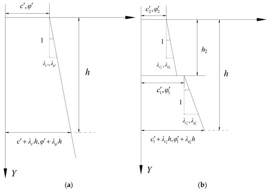
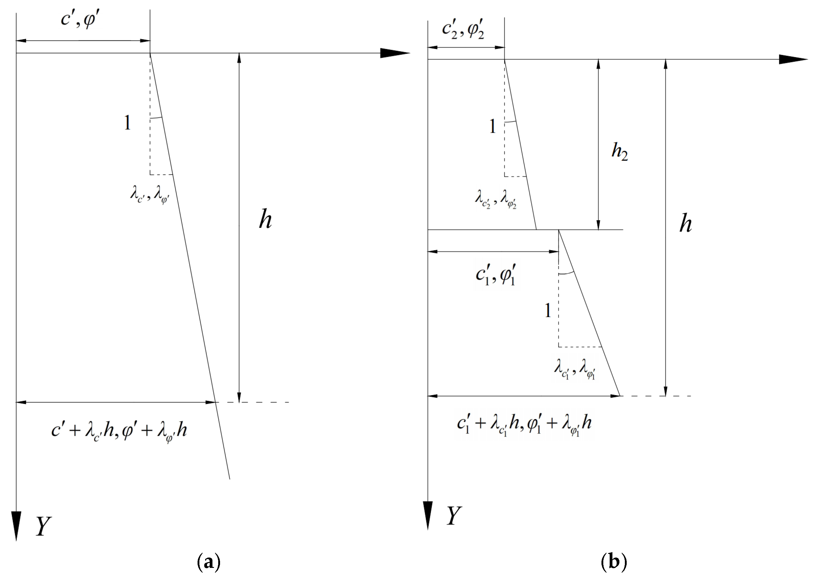
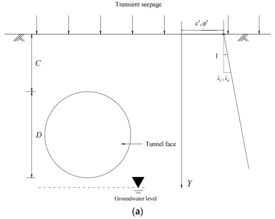
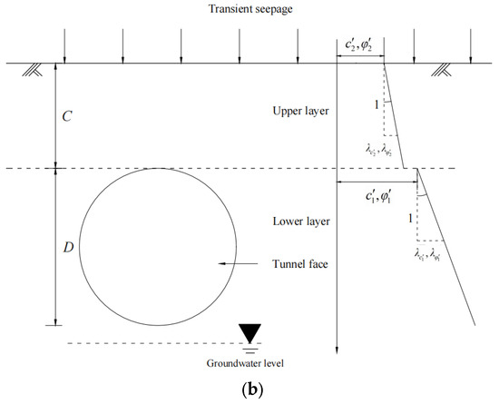
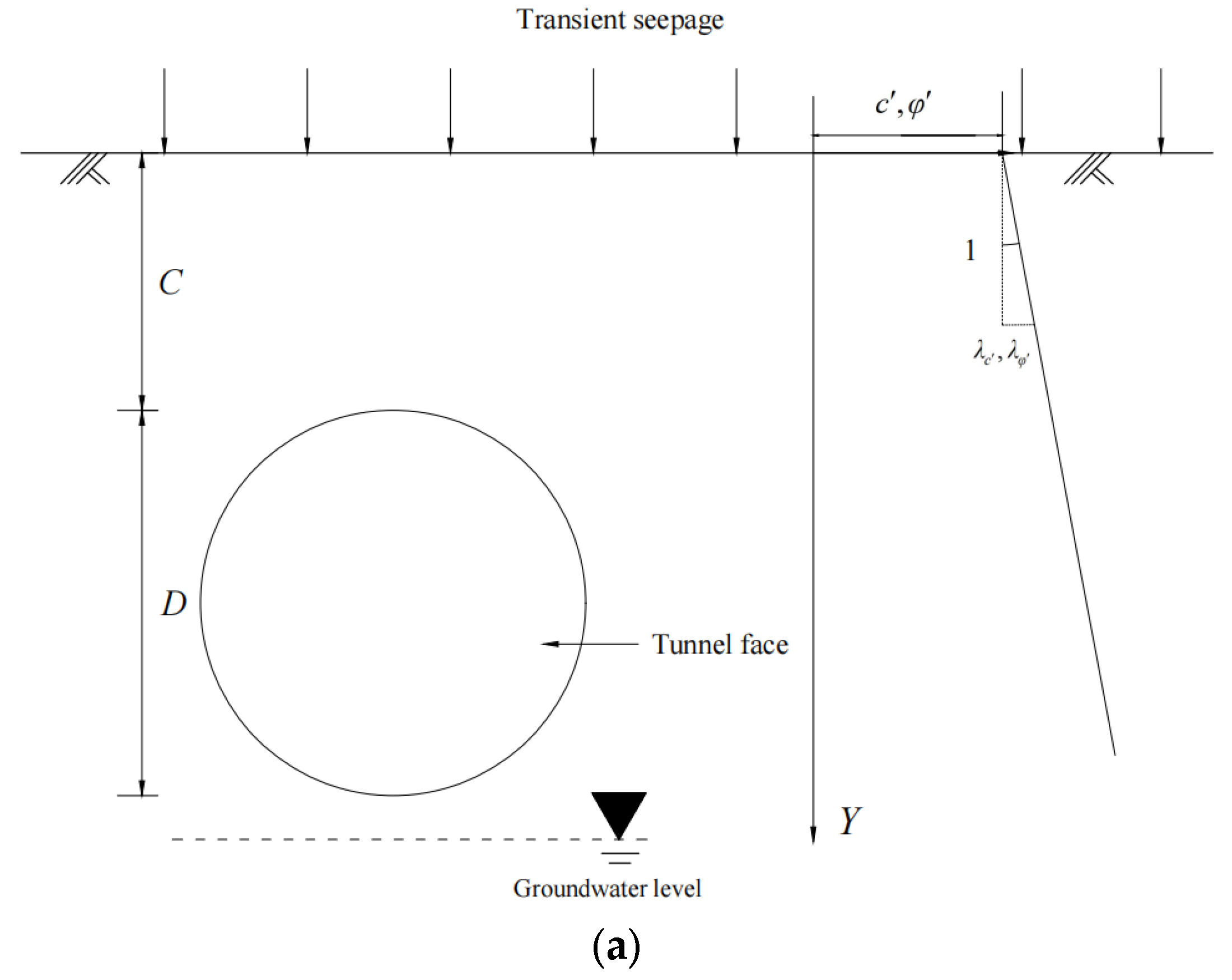
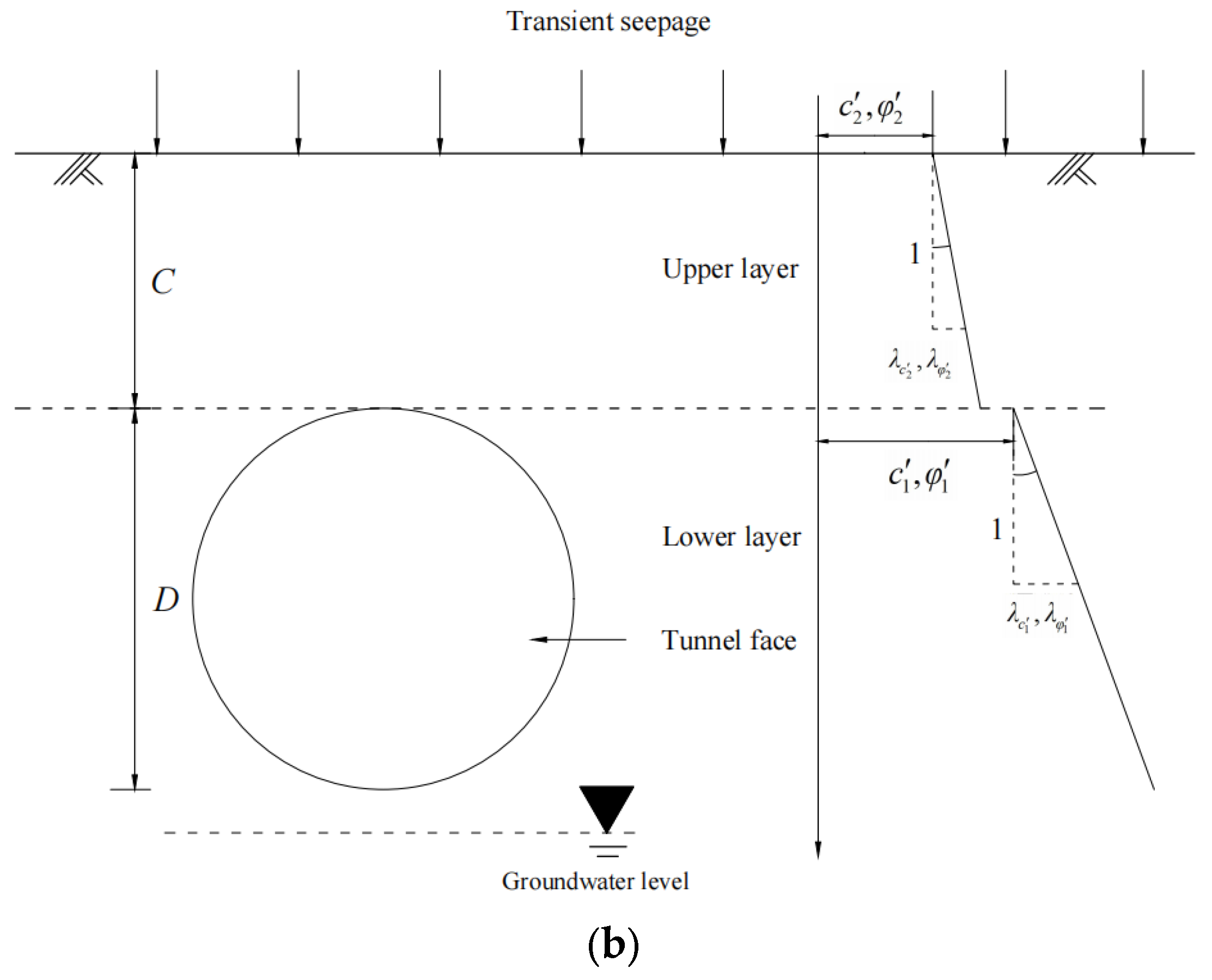
Acknowledging that natural soil heterogeneity typically arises from geostatic consolidation, this study adopts the framework proposed by Augarde et al. (2003) [41]. Accordingly, heterogeneity is characterized specifically by a linear increase in effective cohesion and effective internal friction angle with depth (see Figure 1a); its front view is shown in Figure 2a. Based on these assumptions, the depth-dependent distributions of these strength parameters are formulated as:
where denotes the burial depth; represents the thickness of the upper layer; parameters () and () correspond to the effective cohesion and effective internal friction angle at the reference datum of the lower (or upper) layer, respectively. Furthermore, () and () define the vertical gradients representing the rate of increase in cohesion and friction angle with the depth for the lower (or upper) layer, respectively.
Figure 1.
Distribution model of soil mechanical parameters: (a) heterogeneous soil; (b) heterogeneous dual-layer soil.
Figure 2.
Schematic of the model at the tunnel face: (a) heterogeneous soil; (b) heterogeneous dual-layer soil.
Based on Equation (6), the depth-dependent profiles of effective cohesion and effective internal friction angle for the dual-layer system are illustrated in Figure 1b. Furthermore, within the proposed horizontal dual-layer framework, the crown of the circular tunnel is positioned tangentially to the interface between the upper and lower soil layers, while the groundwater table lies below the tunnel invert. A schematic representation of this geometric configuration is presented in Figure 2b.
2.3. Analytical Solution for Unsaturated Transient Seepage
Previous investigations into unsaturated transient seepage within homogeneous geotechnical structures have predominantly utilized the one-dimensional (1D) vertical Richards’ equation [42,43]. In the context of the heterogeneous dual-layer model proposed in this study, the adoption of a 1D formulation is justified by three key characteristics: (1) the horizontal stratification and lateral homogeneity of the soil ensure that fluid flow is primarily gravity-driven in the vertical direction; (2) the parallel alignment of the layer interface with the horizontal plane renders horizontal flow negligible compared to vertical flow; (3) the 1D Richards’ equation effectively captures vertical heterogeneity, whereas multidimensional formulations would significantly increase computational complexity without offering a commensurate improvement in accuracy. Although real stratigraphy is often not strictly horizontally layered and boundary conditions are usually spatially non-uniform—potentially inducing significant lateral seepage and thereby limiting the validity of the one-dimensional assumption—this study adopts a simplified horizontal two-layer soil model, which still enables the fundamental evolution patterns of tunnel face stability under transient unsaturated seepage to be revealed under controlled conditions. Consequently, the 1D vertical Richards’ equation is adopted to model the unsaturated transient seepage field, expressed as follows [44]:
where denotes time; represents the vertical distance from the specified point to the groundwater table; is the suction head, defined as (where is the unit weight of water); and denotes the unsaturated hydraulic conductivity function. Adopting the constitutive model [45], the expressions for unsaturated hydraulic conductivity and volumetric water content are formulated as:
where represents the saturated hydraulic conductivity; and corresponds to the reciprocal of the vertical height of the capillary fringe. Substituting Equation (8) and Equation (9) into Equation (7) yields:
To solve the aforementioned partial differential equation, appropriate boundary and initial conditions must be imposed. By applying the Laplace transform method in conjunction with these conditions, explicit expressions characterizing the spatiotemporal evolution of unsaturated hydraulic conductivity and suction stress within the heterogeneous stratified soil can be derived.
In the proposed model, the vertical distances from the groundwater table to the layer interface and from the interface to the ground surface are designated as and , respectively. To facilitate the solution of Richards’ equation, a set of dimensionless parameters is introduced. For the lower soil layer, these dimensionless variables are defined as:
where the domain of is ; denotes the initial surface hydraulic flux; and represents the prescribed surface hydraulic flux for . Analogously, for the upper soil layer, the dimensionless parameters are defined as:
where the domain of is defined as . Additionally, the time parameter is non-dimensionalized as follows:
Substituting these dimensionless parameters into Equation (10) yields the simplified governing equations for the stratified soil system:
where the expression for is given by:
Applying the Laplace transform to the aforementioned partial differential equations shifts the problem from the time domain to the complex-frequency domain, effectively reducing the governing partial differential equation to ordinary differential equations. Consequently, the initial conditions for the two soil layers are determined by solving the resulting ordinary differential equations under steady-state seepage conditions:
Based on the model assumptions for heterogeneous strata outlined in the preceding section, the unsaturated hydraulic conductivity is independent of depth and is strictly a function of the suction head . Consequently, assuming zero initial surface flux () and a zero suction head condition at the groundwater table (), the initial suction head distribution within the heterogeneous stratified soil exhibits a linear relationship with the vertical distance from the groundwater table. The expression for this initial distribution is given by:
For , the prescribed hydraulic flux at the ground surface is defined as:
At the interface of heterogeneous soil layers, the model satisfies the conditions of flux continuity and pressure continuity. Specifically, the normal Darcy velocity and matric suction on both sides of the interface remain equal at all times, thereby ensuring that moisture migration between layers adheres to the fundamental continuity requirements of fluid dynamics. The corresponding boundary conditions can be expressed as:
By applying the Laplace transform in conjunction with the established boundary and initial conditions, exact expressions for and in the complex-frequency domain are obtained. Subsequently, the inverse Laplace transform and the Residue Theorem are employed to retrieve the time-domain solutions. This process entails identifying all poles within the Laplace domain and determining the specific time-dependent formulations by summing the residues associated with these poles; the detailed derivation procedure follows the methodology established by Srivastava and Yeh (1991) [46]. It is noteworthy that a simplified analytical solution is attainable only under the condition that the parameter is identical for both the upper and lower soil layers. Based on this premise, the expressions for and are derived as follows:
where denotes the summation of residues derived via the Residue Theorem, and the expressions for and are defined as:
where and denote the positive roots of the following equations:
where the expression for is given by:
The derivation of expressions for and necessitates a case-wise discussion. Specifically, when , , and are determined as the positive roots of the following system of equations:
The corresponding expression for the residue is given by:
The expressions for the corresponding intermediate variables are given by:
where , , and are determined as the positive roots of the following system of equations:
The corresponding expression for the residue is given by:
The expressions for the corresponding intermediate variables are given by:
Thus, the complete analytical expressions of and can be obtained; at this time, the of the upper and lower soil layers have the same value. Although the contrast between distinct values in the upper and lower layers is significant [47], assuming a uniform remains a viable approach for analyzing the influence of the discontinuity in saturated hydraulic conductivity on moisture migration. Consequently, in the subsequent analysis, the parameter is defined as the average of the values for the two layers.
By substituting Equation (3) into Equation (2b), the expression for suction stress is reformulated as:
Based on Equation (8), the expression for the suction head is derived as:
Combining Equation (9) and Equation (49) yields:
Consequently, the expressions for suction stress and apparent cohesion are derived as follows:
3. Failure Mechanism of the Tunnel Face in Nonhomogeneous Soil Layer
3.1. Construction of the Failure Mechanism
Mollon et al. (2011) [11] developed a three-dimensional rotational failure mechanism for the tunnel face by employing double-logarithmic spiral curves and spatial discretization techniques. This model has been extensively utilized in limit analysis studies of tunnel stability; however, its applicability is constrained in heterogeneous soils, primarily because the internal friction angle in such media varies with burial depth. While the classical model facilitates kinematic analysis, it inevitably introduces minor discrepancies compared to actual field conditions. To rigorously evaluate face stability in heterogeneous soil, Li and Yang (2020) [13] proposed a “horizontal layer discretization technique” to construct an adapted failure model. Unlike the conventional approach, this method generates a non-logarithmic spiral failure surface to accommodate the depth-dependent internal friction angle while strictly adhering to the kinematic admissibility of the rotational failure mechanism within each discrete element. Accordingly, this study adopts this methodology to establish the failure mechanism for the heterogeneous dual-layer soil structure.
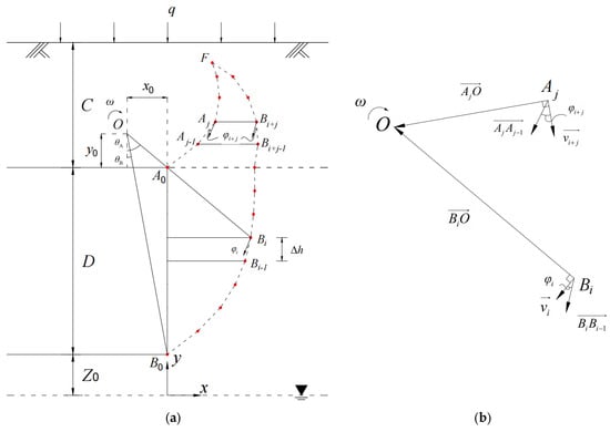
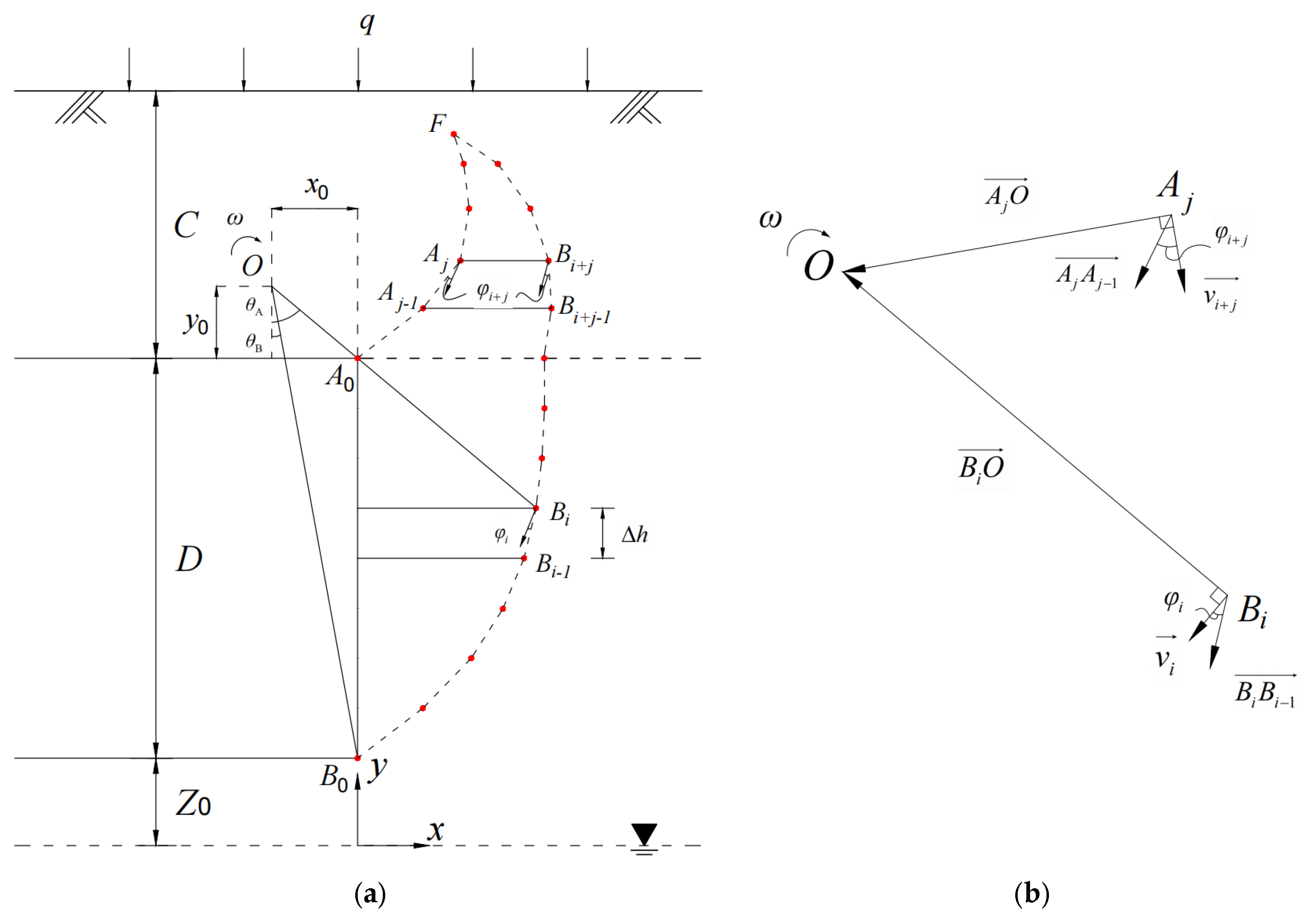
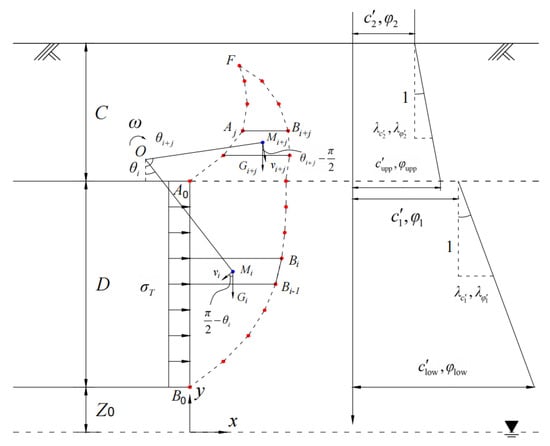
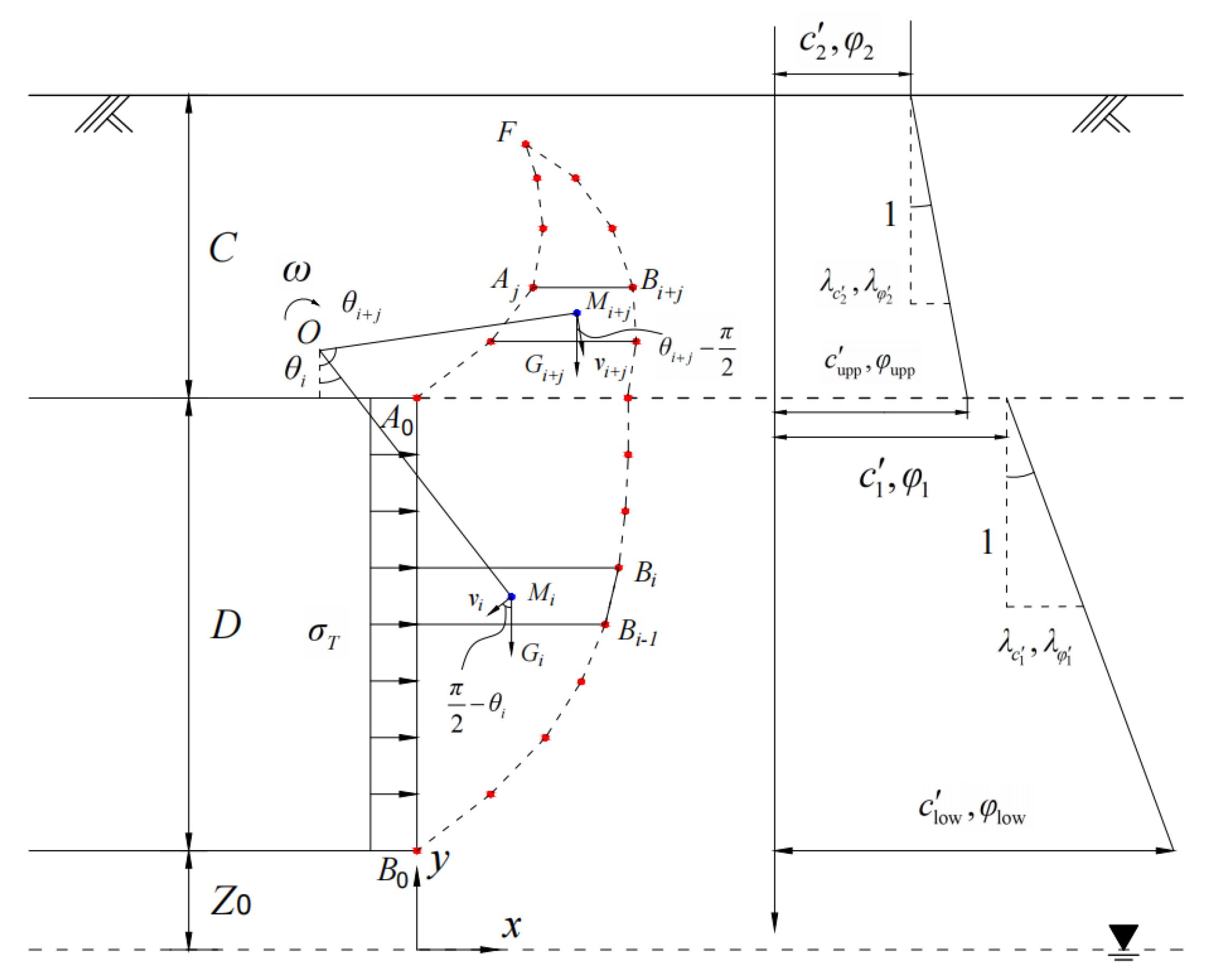
As illustrated in Figure 3a, the tunnel is characterized by the cover depth and diameter . The vertical distance between the tunnel invert and the groundwater table is denoted as , and the tunnel crown is positioned tangentially to the interface, separating the two soil layers. The ground surface is subjected to hydraulic fluxes, where represents evaporation and signifies infiltration. The failure mechanism is defined by two envelopes, and . Unlike the conventional logarithmic spiral formulation, the discrete points constituting these envelopes are generated via a “point-by-point” iterative method to delineate the complete failure surface. This generation process originates at the tunnel crown (point ) and invert (point ) and terminates at point , which is located within the upper soil layer. The enclosed rigid failure block is discretized into multiple horizontal elements, each with a height of . These elements function as rigid bodies with no relative displacement, thereby satisfying the kinematic admissibility conditions of the velocity field.
Figure 3.
Two-dimensional failure mechanism of the tunnel face: (a) horizontal layer discretization technique; (b) vector relationships.
It is noteworthy that, as the tunnel resides entirely within the unsaturated zone, the pore-water pressure is negligible. Consequently, the internal friction angle is approximately equal to the effective internal friction angle. Therefore, in the subsequent analysis, the internal friction angle is utilized to derive the theoretical relationships, whereas the effective internal friction angle is adopted for the actual numerical calculations.
A planar Cartesian coordinate system is established with the origin located on the horizontal plane directly below point . Within this system, the coordinates of the rotation center are denoted as , while the coordinates of points and are defined as and , respectively. Based on the geometric configuration, the expressions for and can be reformulated as:
where and denote the rotation angles between the vertical axis and the radial lines and , respectively. To precisely delineate the failure envelope, an iterative method is employed to determine the coordinates of points and . The geometric relationships governing the generation of and are illustrated in Figure 3b, and the vector formulation for each horizontal element is expressed as:
where and denote the sequential order of point generation. According to the associated flow rule, along the failure envelope (taking point as an example), the angle between the radius of rotation and the velocity discontinuity is defined as , where represents the internal friction angle of the element . Similarly, along the envelope (taking point as an example), this angle is given by . Consequently, the following expressions are derived:
Solving Equation (55) and Equation (56) simultaneously yields:
Consequently, the coordinates of the subsequent points can be iteratively determined from the coordinates of and . The discretization process terminates when the condition is satisfied.
3.2. Calculation of Internal and External Work Rates
In accordance with the heterogeneous soil model established in Section 2.2, the effective cohesion and internal friction angle of the lower soil layer at are prescribed as and , respectively. Similarly, for the upper soil layer, these parameters at the layer interface are defined as and . Accordingly, the effective cohesion and internal friction angle within the failure mechanism are determined as follows:
where and denote the vertical gradients of the internal friction angle with respect to depth for the lower and upper soil layers, respectively. The expressions for , , , and are formulated as follows:
Consequently, the variation in soil strength parameters with burial depth is illustrated in Figure 4.
Figure 4.
Velocity analysis of the tunnel face in the heterogeneous dual-layer soil model.
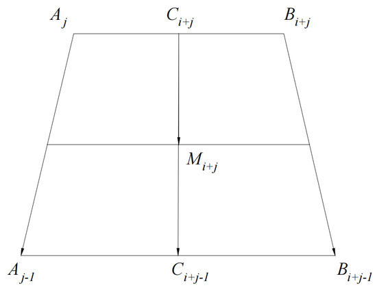
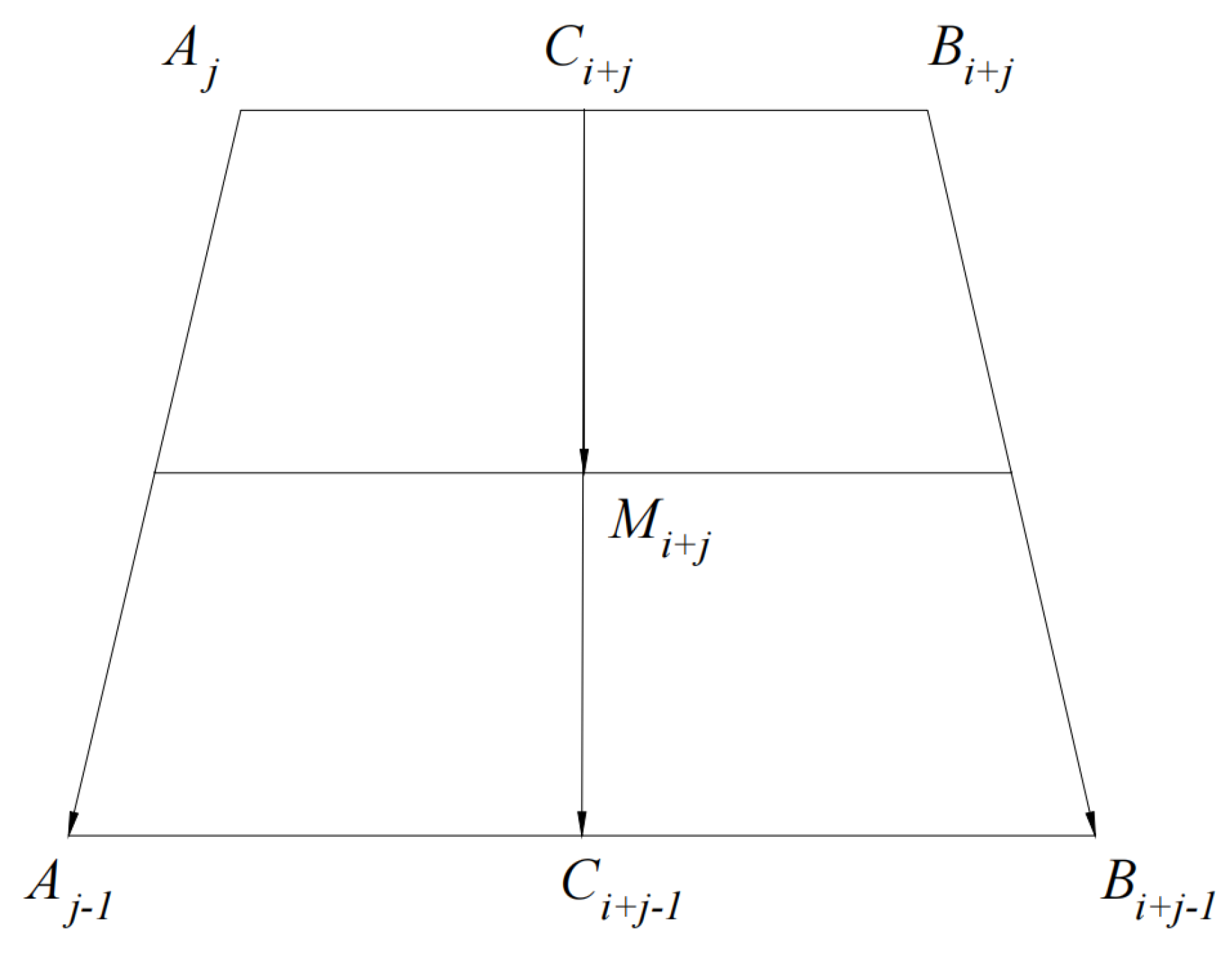
For element , let denote the area, the centroid, and the rotation angle of the centroid. Provided that increment is sufficiently small, each element can be approximated as a homogeneous trapezoidal block, as depicted in Figure 5. In this configuration, and are defined as the midpoints of the vectors and , respectively, while represents a specific point on the vector . Based on these geometric relationships, the following expressions are derived:
Figure 5.
Schematic of centroid coordinates.
The rate of work performed by the self-weight of the soil element within the failure mechanism is expressed as:
where denotes the unit weight of the soil, the value of which is determined by the stratum containing the element’s centroid; and represents the angular velocity of the failure mechanism. Consequently, the total rate of work performed by the soil weight within the failure mechanism is calculated as:
where denotes the total number of soil elements.
Assuming that the support pressure is uniformly distributed across the tunnel face, the work rate performed by the support pressure is expressed as:
The energy dissipation rate of the failure mechanism is generated exclusively along the velocity discontinuity lines, such as and . It is expressed as:
where ; and denote the effective cohesion at the specified discrete points; and represent the corresponding apparent cohesion values. Furthermore, the expressions for and are given by:
According to the principle of virtual work, the following relationship is established:
Consequently, the critical support pressure is determined by optimizing the parameters and . The corresponding mathematical programming formulation is expressed as:
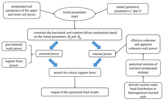
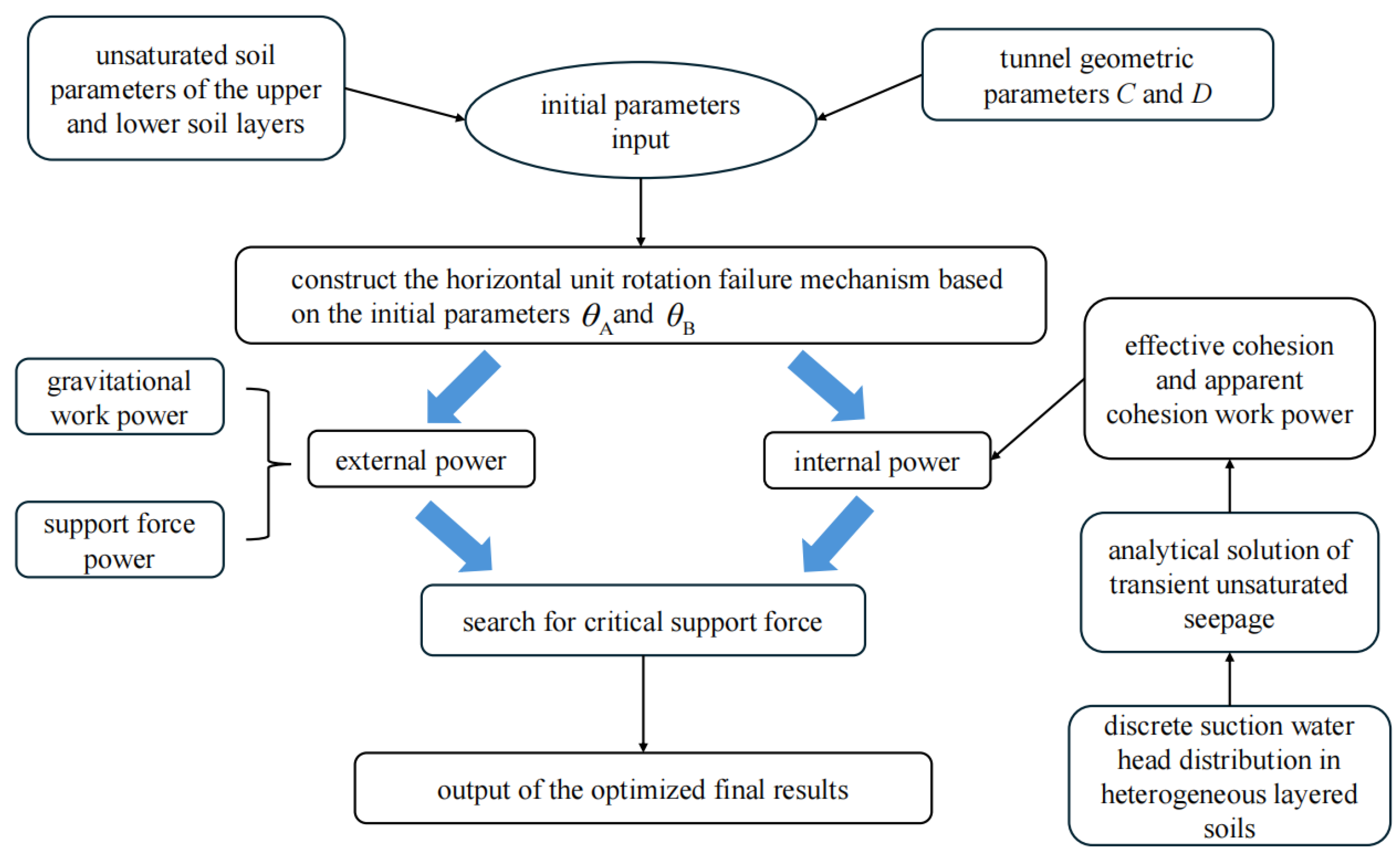
The entire optimization process is implemented within the MATLAB 2024b environment. Specifically, the Monte Carlo algorithm is employed to randomly sample valid angular parameters, after which the optimal solution is identified by maximizing the critical support pressure. A comprehensive computational flowchart is presented in Figure 6.
Figure 6.
Computational flowchart for the tunnel face calculation.
4. Parametric Study
In existing studies, the internal friction angle is frequently utilized as a primary indicator of soil stiffness, where a higher internal friction angle corresponds to greater material stiffness. Accordingly, stratified grounds are generally classified into “upper hard and lower soft” and “upper soft and lower hard” configurations. However, in upper soft and lower hard scenarios, the overlying stratum typically exhibits low permeability and high water-retention capacity. These hydraulic properties impede the vertical propagation of excavation-induced drainage, preventing the formation of a continuous suction profile across the interface. In numerical implementations, this phenomenon often results in solution instability or non-convergence. Consequently, this study exclusively focuses on upper hard and lower soft strata to investigate the correlation between the critical support pressure and the governing parameters.
Meanwhile, to address the problem in “upper soft and lower hard” stratified ground—where an overlying low-permeability, strongly water-retentive soil makes it difficult for excavation-induced drainage effects to propagate upward—a continuous drainage pathway is hard to form near the tunnel face, and seepage calculations become unstable or fail to converge. This paper further proposes a coupled framework that incorporates transient drainage effects into an upper bound analysis of face stability. In this framework, a transient unsaturated seepage model after excavation is established with Richards’ equation as the governing equation, and a seepage-face complementary boundary condition is introduced at the tunnel face. This allows the boundary state to switch adaptively between a pore-water-pressure constraint and a normal-flux constraint, thereby avoiding the over-constraint caused by forcing the entire face to be a drainage boundary. On this basis, the model can still produce stable transient saturation-evolution results under practical conditions where the upper layer is approximately undrained or only locally drained, providing reliable input for subsequently mapping the time-varying seepage field to a time-varying strength field and for conducting upper bound limit analysis.
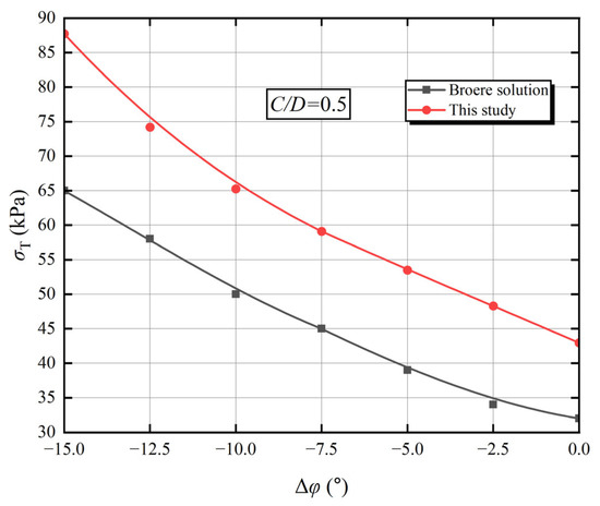
Prior to the parametric analysis, the validity of the proposed framework is verified through a comparative study with the results reported by Broere (2001) [48]. Broere developed a tunnel face stability model for a dual-layer soil system. In that investigation—conducted under the condition of (where , )—the mechanical parameters for the upper soil layer were assigned as effective cohesion , internal friction angle , and unit weight . Conversely, the parameters for the lower layer were defined as , , and , where denotes the difference in the internal friction angle between the lower and upper layers.
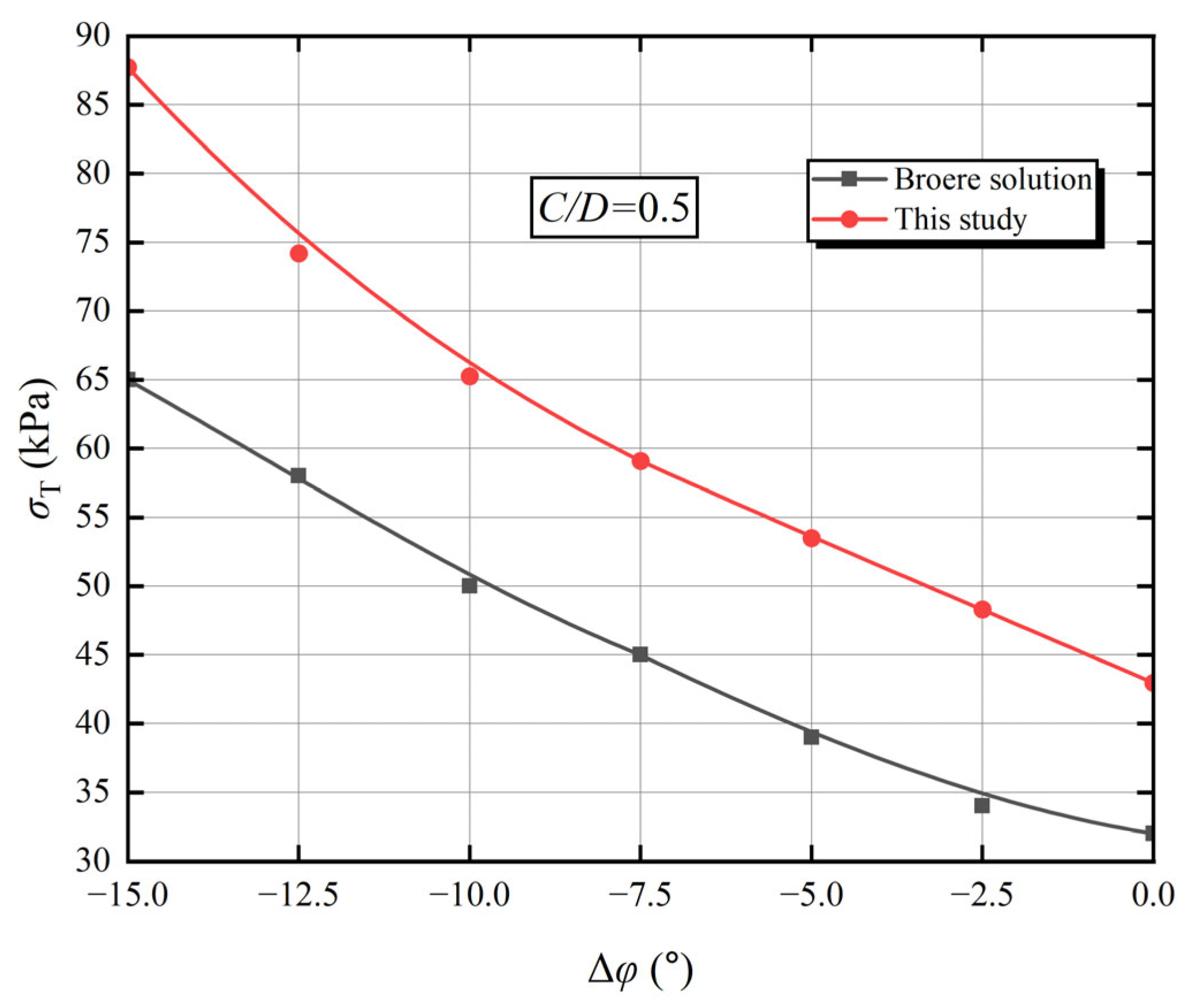
Figure 7 presents a comparative analysis between the results obtained in this study and those reported by Broere [48], illustrating the variation in critical support pressure under different failure mechanism conditions. It is evident that the results yielded by the proposed framework exhibit a trend highly consistent with Broere’s findings, with the critical support pressure showing a uniform magnitude of increase across varying values of . This quantitative discrepancy is attributable to the fundamental differences in the underlying failure models: Broere’s approach relies on the silo model proposed by Horn, which incorporates a friction coefficient and assumes a uniform distribution of lateral earth pressure. Consequently, that method tends to yield lower critical support pressure values, particularly under shallow cover conditions. Despite this magnitude difference, the consistency in the evolutionary trend confirms the validity and accuracy of the proposed analytical framework.
Figure 7.
Comparison with previous studies regarding the variation in critical support pressure with at .
For the subsequent parametric analysis, the unsaturated hydraulic and mechanical parameters for three typical soil types—sand, silt, and clay—were selected based on the literature [43]. The specific physical and mechanical properties of these soils are detailed in Table 1.
Table 1.
Unsaturated hydraulic and mechanical parameters of typical soils.
The scope of this investigation is limited to the specific transient scenario, where the hydraulic regime transitions from an initial no-flow condition to active vertical infiltration. Consequently, all subsequent references to “seepage velocity” denote the prescribed surface hydraulic flux applied during the phase where . Furthermore, the effective cohesion and the effective internal friction angle , listed in Table 1, represent the reference values at the ground surface datum; their specific variation with depth follows the distribution model detailed in Section 3.2.
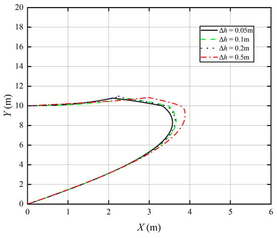
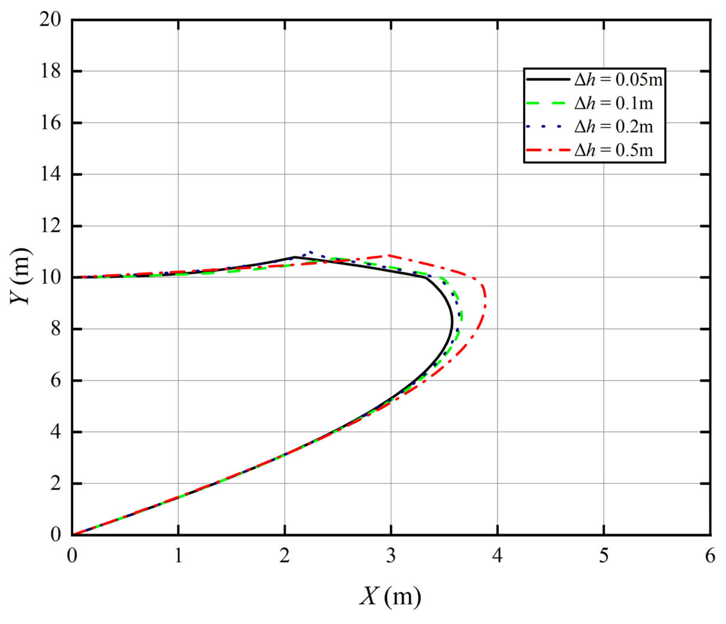
The horizontal layered discretization method divides the tunnel face failure zone vertically into multiple horizontal trapezoidal elements with a height of , thereby approximating the actual failure surface. Consequently, the selected value of directly affects the discrepancy between the discretized failure-zone geometry and the true failure surface, thus influencing the accuracy of the computed results. To investigate the effect of on computational accuracy, this study considers silt–clay stratum as an example and sets to 0.05 m, 0.1 m, 0.2 m, and 0.5 m. The remaining soil parameters are: , , , , and . To facilitate a direct comparison of the results under different conditions, Figure 8 illustrates the corresponding failure-zone configurations. The results indicate that the failure domain obtained from the horizontally layered, discretized failure mechanism exhibits an increasingly pronounced forward inclination as increases. When , the failure-zone geometry is already very close to that obtained with , while the computation time is reduced by approximately 20%. Considering both accuracy and efficiency, although a smaller can improve the estimation accuracy of the critical support pressure, adopting in engineering practice is sufficient to achieve the required accuracy with a lower computational cost.
Figure 8.
Schematic diagram of the failure zone shape of the tunnel face in silt–clay stratum under different values.
Due to the relatively limited data in Table 1, the parameter analysis in this study exhibits certain deterministic characteristics. However, recent research on parameterized fragility surface sensitivity analysis methods [49] has significantly improved the robustness of conclusions and the applicability of results in risk-informed design by constructing a logistic regression fragility model that includes both intensity measures and uncertain parameters, and considering interaction and quadratic terms to describe the coupling effects between parameters. This method holds great potential for application in future research.
4.1. Influence of Groundwater Table Depth on Face Stability
This section investigates the variation in the critical support pressure with respect to the depth of the groundwater table under different stratified soil configurations. The specific geometric and mechanical parameters are defined as:
, , , , , and . Consistent with the methodology described previously, the parameter is calculated as the arithmetic mean of the values for the upper and lower layers, while all remaining properties are adopted from Table 1.
Figure 9 illustrates the variation in critical support pressure with respect to time and groundwater table depth under transient drainage conditions for two distinct strata. Overall, the sand–silt stratum exhibits superior face stability compared to the sand–silt stratum. As the normalized groundwater table depth () increases, the critical support pressure for both conditions displays a non-monotonic trend: initially decreasing, subsequently rising, and ultimately stabilizing. Furthermore, over time, the divergence between the critical support pressure curves for the different time steps gradually diminishes. This convergence indicates that the influence of transient drainage effects on face stability attenuates as the seepage process evolves.
Figure 9.
Critical support pressure versus normalized groundwater table depth for different elapsed times: (a) sand–silt stratum; (b) silt–sand stratum.
The evolution of critical support pressure in the sand–silt stratum is notably complex with respect to groundwater depth. As depicted in Figure 9a, the critical support pressure initially declines with a lowering groundwater table, reaches an inflection point at approximately , and subsequently ascends. Eventually, the rate of increase decelerates, leading to a stabilized plateau. Specifically, within the range of in 0~0.05, the critical support pressure decreases over time, indicating an enhancement in face stability; conversely, in the interval , the critical support pressure rises with time, reflecting a reduction in stability. At , the critical support pressure again decreases with time. However, for , the system exhibits a distinct behavior: the maximum critical support pressure is observed at . Subsequently, for , while the pressure exhibits a gradual temporal increase, it remains below the initial peak at , eventually converging to a steady state.
The time-dependent evolution of the critical support pressure in the sand–silt stratum can be elucidated as a dynamic competition between excavation-induced drainage and background infiltration recharge within the heterogeneous formation. In the shallow groundwater zone (), the upper portion of the failure mechanism is located within the high-permeability sand layer. Consequently, excavation-induced pore-water pressure dissipates rapidly, allowing matric suction and apparent cohesion to establish and strengthen significantly over a short period. This drainage-induced strengthening effect dominates the soil strength evolution and effectively counteracts the influence of background infiltration, resulting in a monotonic decrease in critical support pressure over time; conversely, in the transition zone (), the low permeability of the underlying silt layer causes a significant lag in the expansion of the suction front. Simultaneously, the overlying high-permeability sand acts as a preferential conduit, continuously transmitting surface infiltration flux to the layer interface. In this scenario, the infiltration-induced softening effect at the top of the slip body outweighs the marginal drainage strengthening, leading to a gradual increase in support pressure over time. As the water table descends further (), the failure mechanism progressively detaches from the influence of the inter-layer moisture recharge boundary. Consequently, the drainage consolidation mechanism within the silt layer reestablishes dominance, promoting self-stabilization of the stratum. In the deep groundwater zone (), the critical support pressure peaks initially () because the drainage lag in the low-permeability silt prevents effective suction coverage of the slip surface, keeping the soil in an initially wet state. Subsequently, while the advancement of the suction front significantly reduces the required support, the continuous background recharge and pore-pressure redistribution drive the soil from a transient drying peak toward a long-term unsaturated steady state, manifesting as a slight temporal rebound in support pressure.
Macroscopically, the evolution of strength is governed by the hydraulic state of the soil relative to the groundwater table. When the groundwater table is near the tunnel invert, the soil surrounding the face is saturated. A lowering of the water table reduces volumetric water content and increases matric suction, thereby generating additional apparent cohesion and enhancing soil strength. However, as the water table continues to drop beyond a critical threshold, the pore water becomes discontinuous. Although matric suction continues to increase, its effective transmission is impeded by the reduction in the wetted area of particle contacts; consequently, apparent cohesion begins to decay, resulting in a reduction in soil strength. When the groundwater table descends below the capillary rise height, the volumetric water content approaches the residual water content, and the soil strength eventually stabilizes.
Figure 9b illustrates the variation in critical support pressure with groundwater table depth in the silt–clay stratum. While the overall trend parallels that of the sand–silt stratum, the temporal evolution is distinctively monotonic. As time progresses, the critical support pressure decreases steadily, indicating the gradual stabilization of the tunnel face. This behavioral divergence is likely attributable to fundamental differences in soil hydraulic properties and inter-layer hydraulic interaction mechanisms. In the silt–clay stratum, the silt layer possesses excellent water-retention capacity and a broad range for sustaining matric suction. Consequently, under excavation-induced drainage, the soil is maintained within the capillary conduction regime, preserving high suction levels. Furthermore, the underlying low-permeability clay layer effectively impedes inter-layer hydraulic interference, allowing drainage consolidation effects to remain dominant. This mechanism is macroscopically manifested as a monotonic reduction in critical support pressure over time.
4.2. Influence of Cover-to-Diameter Ratio on Face Stability
This section investigates the variation in the critical support pressure with respect to the cover-to-diameter ratio under different stratified soil configurations. The specific geometric and mechanical parameters are defined as: , , , , and . The parameter is calculated as the arithmetic mean of the values for the upper and lower layers, while all remaining properties are adopted from Table 1.
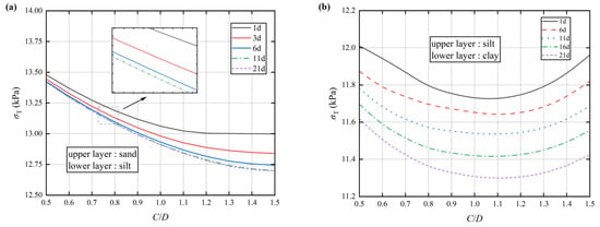
Figure 10 illustrates the variations in critical support pressure with respect to time and the cover-to-diameter () ratio for two stratified soil configurations under transient drainage conditions. It is evident that for both the sand–silt and silt–clay strata, the critical support pressure decreases monotonically over time across varying ratios. Overall, the critical support pressure in the silt–clay stratum exhibits a more pronounced sensitivity to temporal effects.
Figure 10.
Critical support pressure versus cover-to-diameter ratio for different elapsed times: (a) sand–silt stratum; (b) silt–clay stratum.
Figure 10a specifically characterizes the evolution of critical support pressure in the sand–silt stratum. The support pressure demonstrates a non-linear, monotonic decrease as the ratio increases, with the rate of decline gradually attenuating towards convergence. Regarding temporal evolution, significant variations in critical support pressure are observed during the initial phase, followed by rapid stabilization. Notably, the sensitivity of the support pressure to time is positively correlated with the ratio, implying that as the burial depth increases, the influence of time on tunnel face stability becomes increasingly significant.
The evolution of critical support pressure in the sand–silt stratum with respect to the ratio and time can be attributed to the coupled mechanism of soil arching effect and transient suction diffusion. As the ratio increases, the matric suction induced by excavation drainage generates significant apparent cohesion across the expanding overburden. This facilitates the transformation of the overlying soil from a simple gravitational load into a “suction-reinforced arch” with self-bearing capacity. This enhanced soil arching effect effectively relieves the vertical earth pressure acting on the tunnel face, resulting in the observed non-linear monotonic decrease and gradual convergence of the critical support pressure.
Regarding the temporal evolution, Darcy’s law indicates that during the initial stage of excavation, the hydraulic head difference between the tunnel face and the surrounding formation is maximized. This results in an extremely high hydraulic gradient, causing the rates of drainage and suction accumulation to peak. Consequently, the critical support pressure exhibits a significant initial response, followed by rapid stabilization as the pore-water pressure equilibrates. Furthermore, the positive correlation between time sensitivity and burial depth arises because, as the depth increases, the geostatic stress of the potential failure mass increases significantly. Under these conditions, the bearing capacity contributed by the soil arching effect becomes more prominent, thereby amplifying the reduction in critical support pressure.
Figure 10b depicts the evolution of critical support pressure in the silt–clay stratum with respect to the cover-to-diameter () ratio and time. The critical support pressure initially decreases as the ratio increases, with the rate of decline gradually attenuating until a critical inflection point is reached. Beyond this threshold (), the pressure begins to increase at an accelerating rate. It is observed that across varying ratios, the influence of the time parameter on the critical support pressure remains substantially uniform.
The non-monotonic evolution of critical support pressure in the silt–clay stratum can be attributed to a shift in the dynamic equilibrium of forces as burial depth increases. In the shallow burial stage (where ), the overlying silt layer acts as an excellent water-retention medium. Under excavation-induced drainage, it rapidly develops high matric suction and apparent cohesion. Similar to the sand–silt stratum, as the layer thickness increases, the formation of a soil arch significantly enhances the self-bearing capacity of the ground, effectively offsetting and exceeding the geostatic load. This results in a reduction in critical support pressure with increasing depth. However, once the ratio exceeds the critical threshold (where ), a mechanistic reversal occurs. Constrained by the relatively low permeability coefficients of the silt and the underlying clay, the excavation-induced transient suction front cannot propagate upward indefinitely within a finite time. Consequently, the additional overburden soil far from the tunnel face fails to gain significant suction reinforcement. As a result, geostatic stress becomes the dominant factor, causing the support pressure to rise at an accelerative rate after the critical point. From this phenomenon, it can be concluded that in silt–clay stratum, tunnel face stability is optimal when the cover-to-diameter ratio is approximately 1.1. This stands in contrast to the monotonic decrease observed in the sand–silt stratum; the root cause of this divergence lies in the distinct soil hydraulic properties. While the high permeability of sand allows the suction-reinforced zone to rapidly encompass deep soil layers and maintain long-term unloading effects, the silt–clay combination is restricted by the limited radius of influence of transient drainage. This limitation prevents the sustenance of high suction under deep burial conditions, resulting in the characteristic “U-shaped” non-monotonic evolution.
4.3. Influence of Heterogeneity Coefficient on Face Stability
This section investigates the variation in the critical support pressure with respect to the heterogeneity coefficient under different stratified soil configurations. The specific geometric and mechanical parameters are defined as: , , , , , and . The parameter is calculated as the arithmetic mean of the values for the upper and lower layers, while all remaining properties are adopted from Table 1.
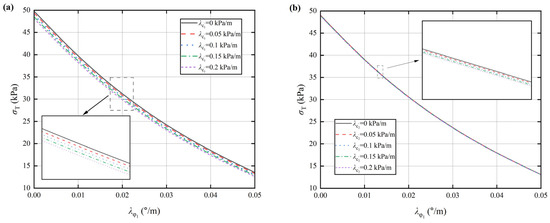
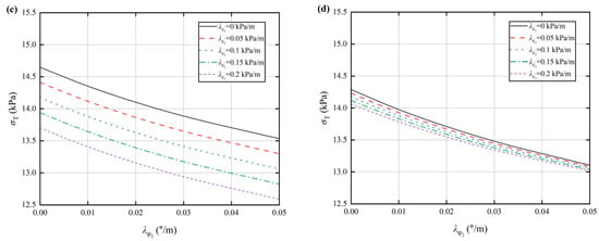
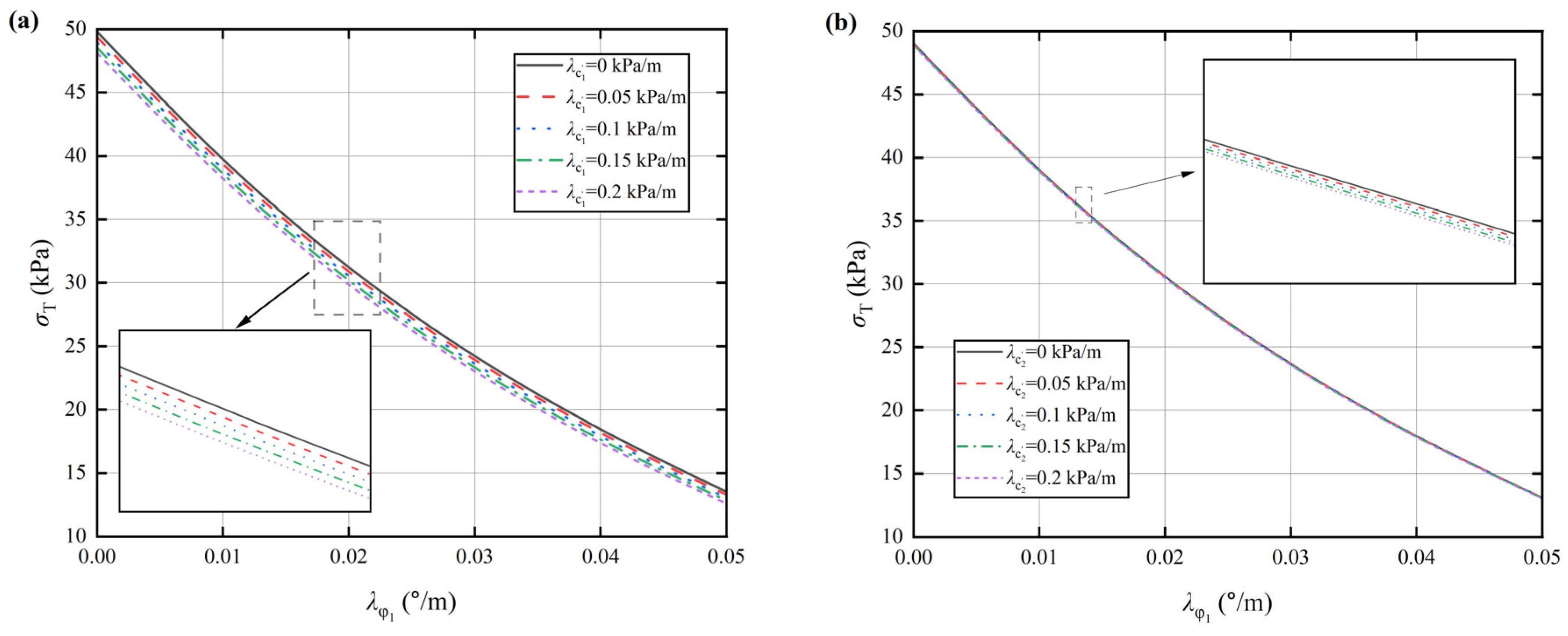
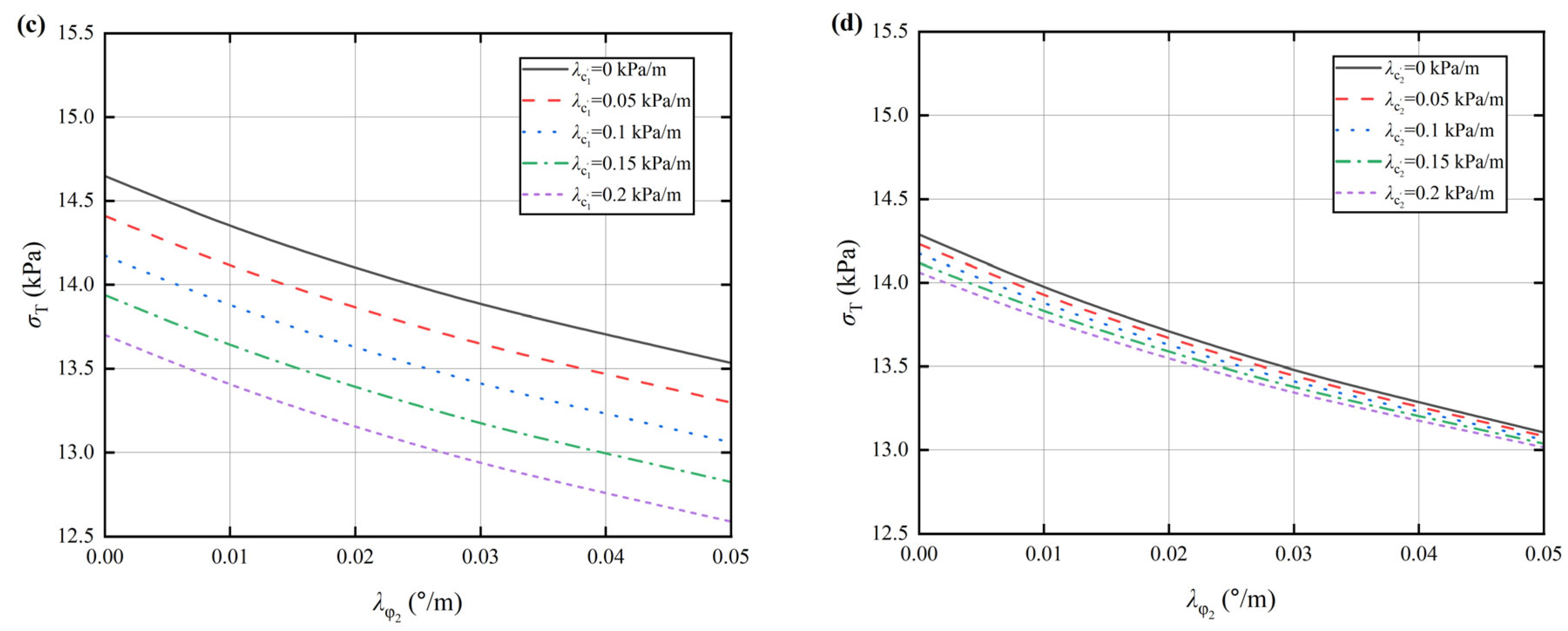
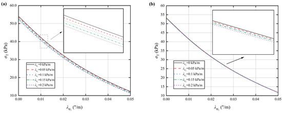
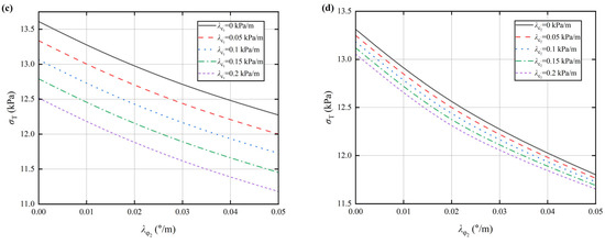
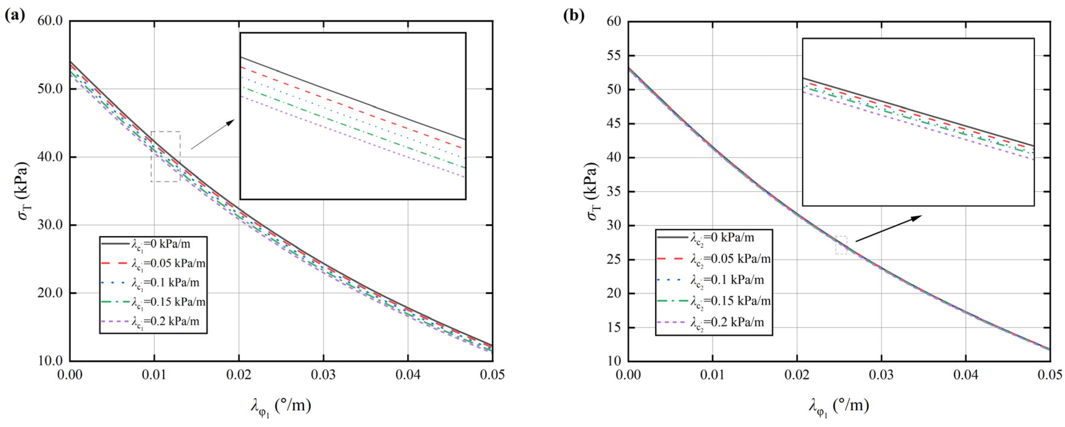
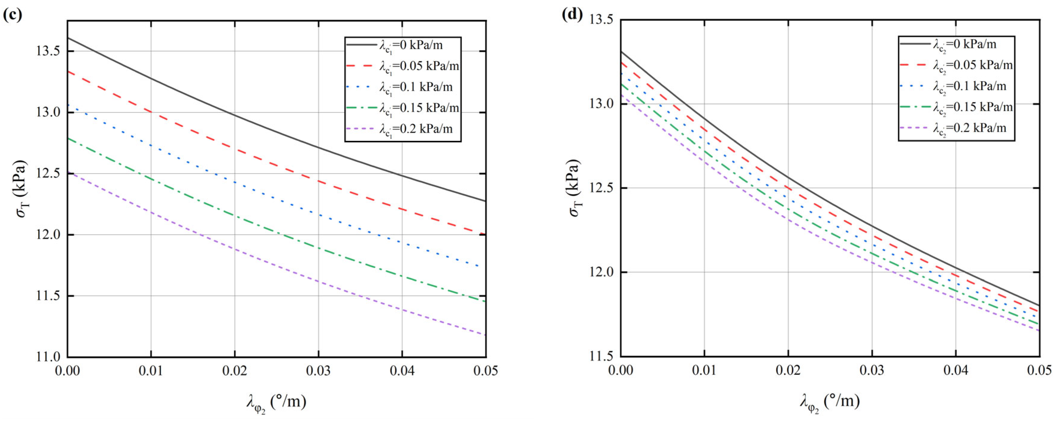
Figure 11 and Figure 12 illustrate the variations in critical support pressure for two distinct stratigraphic scenarios under different heterogeneity coefficients (). In both cases, the critical support pressure exhibits a consistent downward trend as the four heterogeneity coefficients increase. That is, an increase in any constituent parameter of facilitates the stabilization of the tunnel face.
Figure 11.
Variations in critical support pressure under different heterogeneity coefficients in the sand–silt stratum: (a) versus for different ; (b) versus for different ; (c) versus for different ; (d) versus for different .
Figure 12.
Variations in critical support pressure under different heterogeneity coefficients in the silt–clay stratum: (a) versus for different ; (b) versus for different ; (c) versus for different ; (d) versus for different .
Simultaneously, it is evident that the critical support pressure decreases linearly with the increase in , whereas it exhibits a non-linear decrease—with a gradually attenuating rate—as increase. More specifically, the critical support pressure displays low sensitivity to variations in , while responding significantly to changes in . Overall, the influence of the lower layer’s heterogeneity coefficients () on the critical support pressure surpasses that of the upper layer’s coefficients (). The specific hierarchy of influence can be expressed as .
The underlying mechanism is that as the heterogeneity coefficients increase, the shear strength of the overall soil formation improves significantly. This results in a substantial increase in the energy dissipation rate within the failure mechanism, which is macroscopically manifested as a monotonic decrease in support pressure with increasing heterogeneity coefficients. Specifically, the effective cohesion gradient increases the soil’s effective cohesion only in a linear manner; consequently, its influence on support pressure is linear and exhibits low sensitivity. In contrast, the internal friction angle gradient not only significantly enhances the frictional strength of the soil skeleton via the tangent function, but also amplifies the excavation-induced matric suction effect through the apparent cohesion formulation. This dual action causes the support pressure to demonstrate a highly sensitive, non-linear response to the internal friction angle gradient.
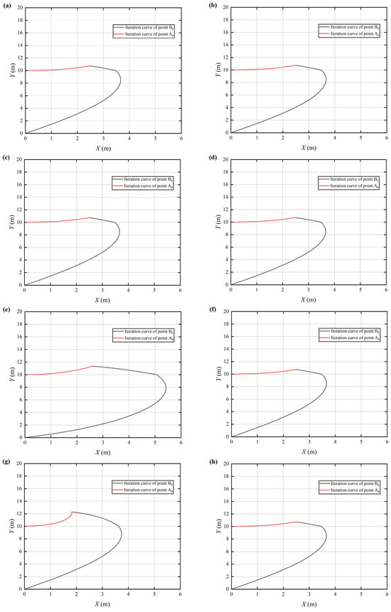
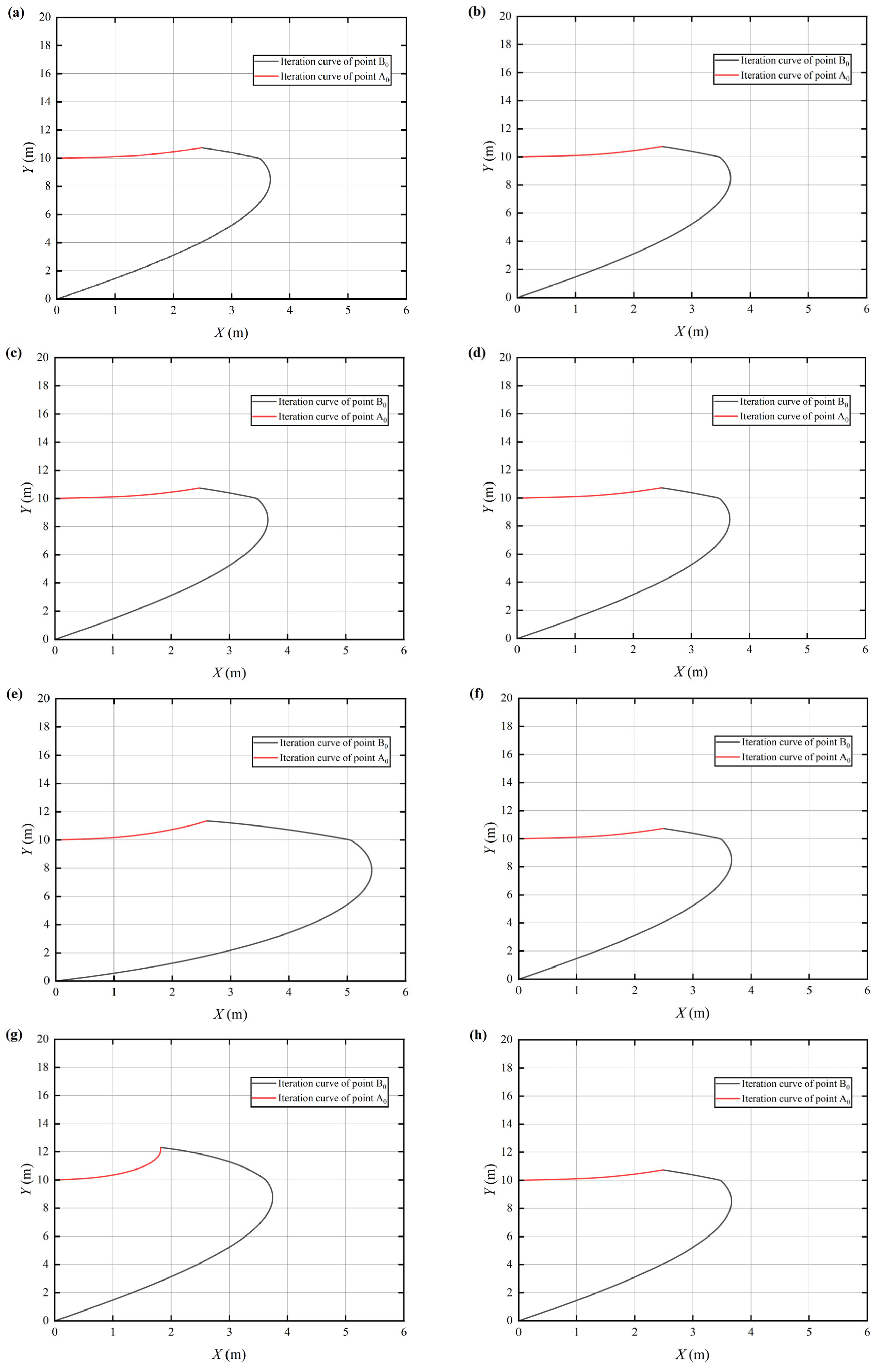
Furthermore, the potential failure zone at the tunnel face is predominantly located within the lower soil layer. Under the soil arching effect, the deep slip surface tends to contract. Consequently, the strength parameters of the lower layer play a dominant role in maintaining global stability, rendering the influence of the upper layer parameters relatively secondary. Figure 13 illustrates the morphological characteristics of the failure zone in silt–clay stratum under different heterogeneity coefficients. Since only a single heterogeneity coefficient is varied in each case, the failure zone morphologies in Figure 13b,d,f,h are identical; they serve as a control group to isolate and evaluate the influence of each coefficient on tunnel face stability. It is evident from Figure 13 that the effective cohesion gradient has a negligible effect on the failure zone’s morphology. In contrast, the internal friction angle gradient exerts a significant influence. Furthermore, the impact of the lower layer’s heterogeneity coefficient on the failure zone’s morphology is more pronounced. In summary, the hierarchy of influence regarding heterogeneity parameters on face stability is characterized by the dominance of the “internal friction angle effect over the effective cohesion effect” and “lower-layer control over upper-layer control.”
Figure 13.
Schematic diagram of failure zone morphology in silt–clay stratum under different heterogeneity coefficients: (a) ; (b) ; (c) ; (d) ; (e) ; (f) ; (g) ; (h) .
4.4. Influence of Seepage Velocity on Face Stability
This section investigates the variation in the critical support pressure with respect to the depth of the groundwater table under different stratified soil configurations. The specific geometric and mechanical parameters are defined as: , , , , and . The parameter is calculated as the arithmetic mean of the values for the upper and lower layers, while all remaining properties are adopted from Table 1.
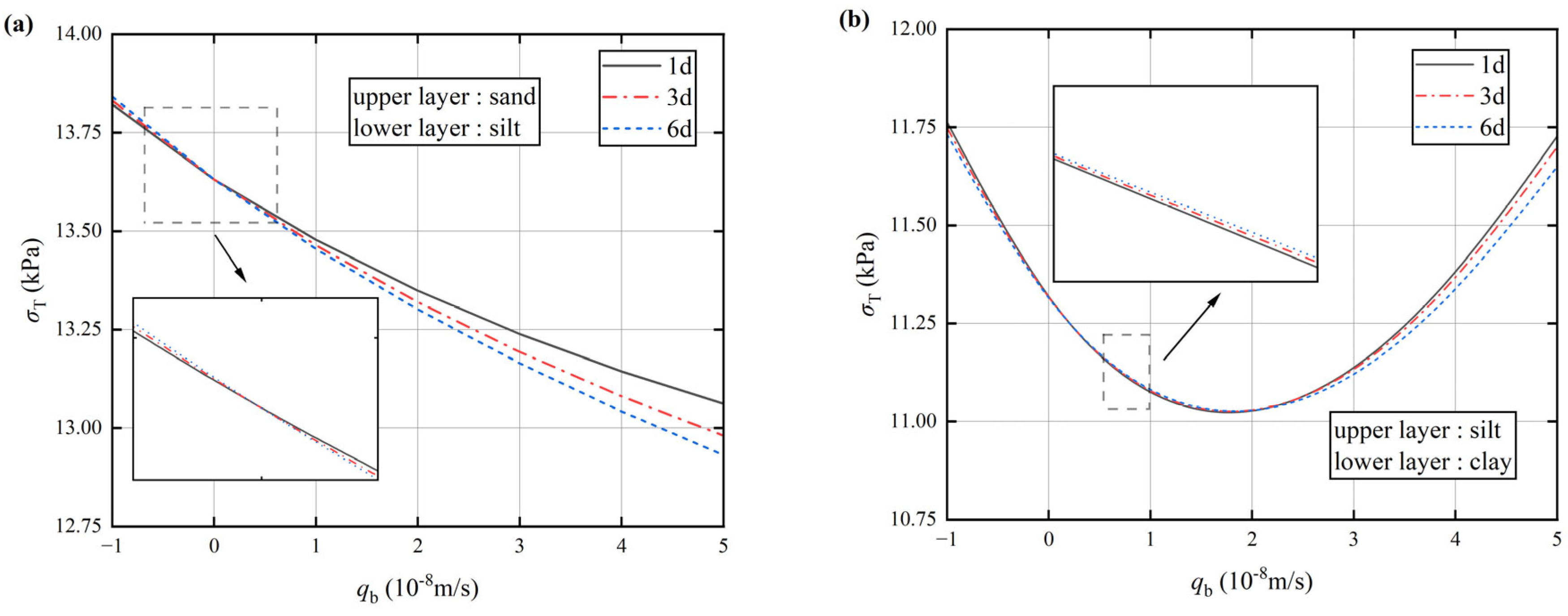
As illustrated in Figure 14a, the critical support pressure in the sand–silt stratum exhibits a monotonic decrease as increases during the transition from evaporation to infiltration. Regarding the temporal evolution, when the stratum is subjected to evaporation (), the critical support pressure increases with elapsed time. In the absence of seepage (), the support pressure remains time-independent. Conversely, under infiltration conditions (), the critical support pressure gradually diminishes over time, with the divergence in pressure values becoming more pronounced as increases.
Figure 14.
Critical support pressure versus seepage velocity for different elapsed times: (a) sand–silt stratum; (b) silt–clay stratum.
Conversely, in the silt–clay stratum, the variation in critical support pressure with seepage velocity—ranging from evaporation to infiltration—is non-monotonic. As depicted in Figure 14b, the critical support pressure initially exhibits a decelerating decline, followed by an accelerating rise as increases, forming a characteristic U-shaped curve.
The temporal evolution in this stratum contrasts sharply with that of the sand–silt stratum. Specifically, under evaporation conditions (), the critical support pressure decreases over time. In the no-flow condition (), the pressure remains constant. Under low infiltration conditions (), the support pressure gradually increases over time; however, this trend reverses under high infiltration conditions (), where the divergence in support pressure values widens as increases. At the same time, from the phenomenon in the silt–clay stratum, it can be seen that when the seepage velocity of the excavation drainage is , the critical support force at the face is minimal, and the stability is strongest.
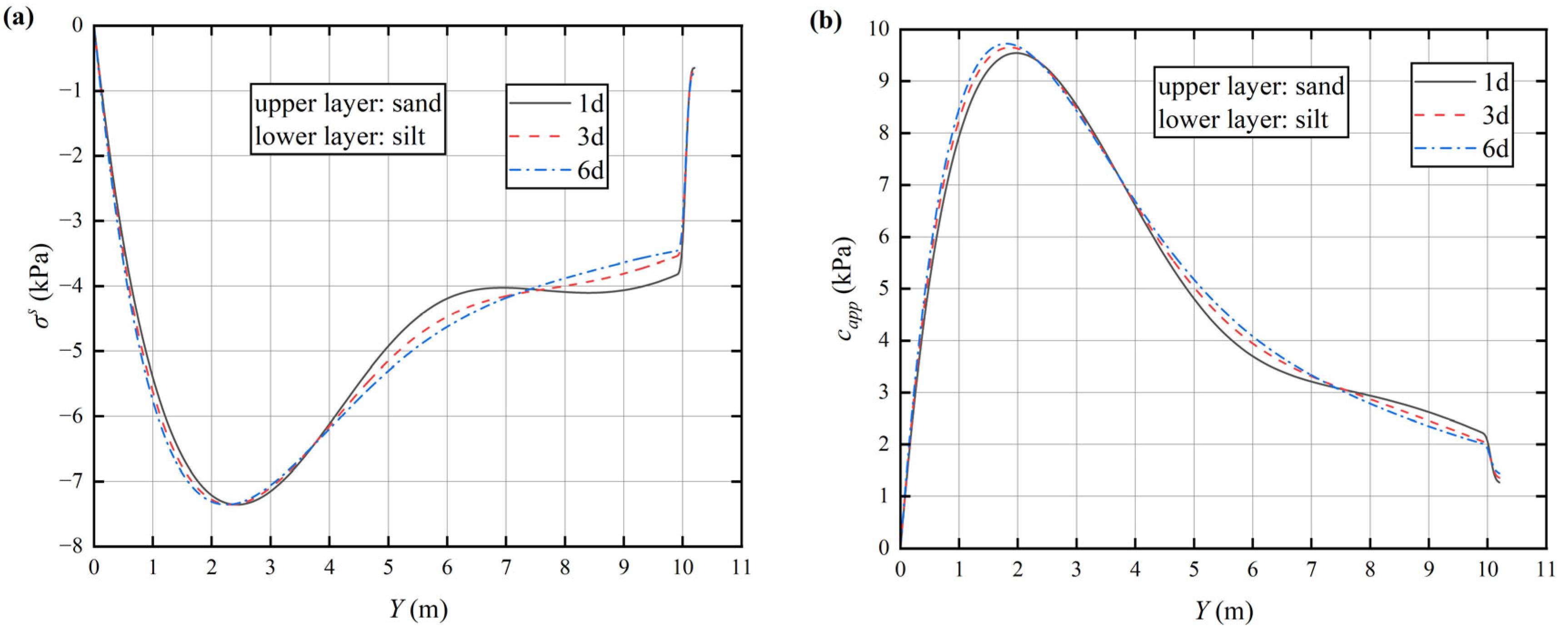
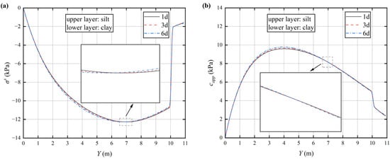
As shown in Figure 15 and Figure 16, the discrepancy in trends between the two scenarios is likely attributable to fundamental differences in soil hydraulic properties. The high permeability of the sand stratum facilitates the rapid expansion of drainage effects, leading to a swift enhancement of matric suction that consistently reduces critical support pressure. In contrast, the silt–clay stratum, characterized by low permeability and high water retention, exhibits limited drainage efficiency. Consequently, the interplay between suction gain and temporal effects is significantly more complex, resulting in distinctly different responses to seepage and time.
Figure 15.
Spatial distribution of suction stress and apparent cohesion within the failure zone of the sand–silt stratum face under different time conditions: (a) suction stress; (b) apparent cohesion.
Figure 16.
Spatial distribution of suction stress and apparent cohesion within the failure zone of the sand–silt stratum face under different time conditions: (a) suction stress; (b) apparent cohesion.
5. Conclusions
The analytical framework established in this study advances the traditional understanding of tunnel face stability. It represents a novel integration of excavation-induced unsaturated transient seepage with soil heterogeneity, thereby extending the upper bound theorem to more complex engineering scenarios. Through the derivation of an analytical solution for one-dimensional vertical unsaturated transient seepage, the quantification of suction stress and apparent cohesion within the unsaturated soil is achieved. This formulation is subsequently incorporated into the heterogeneous soil model assumptions and the unsaturated shear strength criterion. By constructing a power balance equation based on a horizontally discretized failure mechanism, the critical support pressure—accounting for the spatiotemporal effects of transient drainage—is determined. The validity of the proposed framework is corroborated through comparative verification. Based on a parametric analysis of typical “ upper hard and lower soft ” stratigraphic profiles, the following conclusions are drawn:
Under the influence of unsaturated transient seepage, the critical support pressure of the tunnel face in “upper hard and lower soft” strata is significantly governed by factors including time, groundwater table depth, cover-to-diameter () ratio, heterogeneity coefficients, and seepage velocity. Generally, the sand–silt stratum exhibits lower stability compared to the silt–clay stratum. Furthermore, its sensitivity to groundwater depth and temporal factors is more pronounced and complex. Additionally, in both stratigraphic scenarios, the critical support pressure decreases overall with the passage of time, with the response curves gradually converging. This indicates that the effects of unsaturated transient seepage tend to stabilize over the long term, while exerting a more significant influence on critical support pressure in the short term.
Regarding the sensitivity of the parameters in “upper hard and lower soft” strata, the impact of the lower layer’s internal friction heterogeneity coefficient on the critical support pressure significantly outweighs the influence of seepage velocity. Conversely, the influence of the remaining heterogeneity coefficients is lower than that of the seepage velocity. For instance, in the silt–clay stratum, when the seepage velocity reaches , the soil approaches saturation. The resulting critical support pressure is approximately 35.77% higher than that observed under peak suction conditions (). However, the variation in support pressure induced by changes in spans a range of approximately 352.89%, far exceeding the seepage-induced variation. In contrast, the variations attributed to are approximately 9.78%, 1.28%, and 11.40%, respectively, all of which remain below the level of influence exerted by seepage velocity.
The results of the parametric analysis indicate that in “upper hard and lower soft” strata, the unsaturated transient seepage effect is notably significant only under specific conditions: during the early stage of excavation drainage (), or in the presence of low groundwater table depths (), high cover-to-diameter ratios (), or high seepage velocities (). Incorporating this effect into engineering practice can significantly improve the precision of support pressure design. Conversely, in other scenarios, the unsaturated transient seepage effect can be disregarded, as it tends to dissipate gradually throughout the seepage process.
In this study, when constructing a transient unsaturated seepage model, we obtained a simplified analytical solution by assigning the same value of to both layers. This treatment is equivalent to assuming that the two soil layers have similar pore-size distribution shapes; the stratification difference is reflected mainly in an abrupt change in the parameter. Therefore, this assumption is applicable to stratified systems with similar parent materials and structures where differences in hydraulic conductivity magnitude arise only from compaction, disturbance, or bedding. In contrast, when soil types differ substantially and the system lies in a strongly non-linear, near-saturated regime, the applicability of this assumption—and the corresponding analytical solution—is significantly limited. In such cases, numerical methods capable of handling layer-to-layer differences in should be used in preference.
Future research should focus on extending the tunnel face failure mechanism and Richards’ equation for transient unsaturated seepage into three-dimensional space, while employing the finite difference method to apply this analytical framework to “upper soft and lower hard” strata. This advancement will enable a more precise characterization of the impact of transient seepage on face stability, thereby providing a more solid scientific basis for stability assessment in heterogeneous grounds.
Author Contributions
Conceptualization, J.W.; Methodology, J.W.; Software, W.S.; Validation, D.Z.; Formal Analysis, G.L.; Investigation, L.X.; Resources, L.X.; Writing—Original Draft, W.S.; Supervision, D.Z.; Project Administration, G.L. All authors have read and agreed to the published version of the manuscript.
Funding
This work was supported by the project “Key technologies for deformation control in shield tunneling through operated subway station and utility tunnels” from Shenzhen Municipal Group Co., Ltd.
Data Availability Statement
The original contributions presented in this study are included in the article. Further inquiries can be directed to the corresponding author.
Conflicts of Interest
Authors Long Xia, Guihua Long and Jian Wang were employed by the Shenzhen Municipal Group Co., Ltd. The remaining authors declare that the research was conducted in the absence of any commercial or financial relationships that could be construed as a potential conflict of interest.
References
- Lee, C.J. Numerical analysis of pile response to open face tunnelling in stiff clay. Comput. Geotech. 2013, 51, 116–127. [Google Scholar] [CrossRef] [Scilit]
- Yang, X.L.; Wang, J.M. Ground movement prediction for tunnels using simplified procedure. Tunn. Undergr. Space Technol. 2011, 26, 462–471. [Google Scholar] [CrossRef] [Scilit]
- Buhan, P.D.; Cuvillier, A.; Dormieux, L.; Maghous, S. Face stability of shallow circular tunnels driven under the water table: A numerical analysis. Int. J. Numer. Anal. Methods. Geomech. 1999, 23, 79–95. [Google Scholar] [CrossRef] [Scilit]
- Idinger, G.; Aklik, P.; Wu, W.; Borja, R.I. Centrifuge model test on the face stability of shallow tunnel. Acta Geotech. 2011, 6, 105–117. [Google Scholar] [CrossRef] [Scilit]
- Yang, X.L.; Yin, J.H. Upper bound solution for ultimate bearing capacity with a modified Hoek-Brown failure criterion. Int. J. Rock Mech. Min. Sci. 2005, 42, 550–560. [Google Scholar] [CrossRef] [Scilit]
- Anagnostou, G.; Perazzelli, P. Analysis method and design charts for bolt reinforcement of the tunnel face in cohesive-frictional soils. Tunn. Undergr. Space Technol. 2015, 47, 162–181. [Google Scholar] [CrossRef] [Scilit]
- Shan, J.T.; Yang, X.L.; Xia, L.; Long, G.H.; Yang, B.Y.; Ren, L.W. Influence of plant root reinforcement on 3D geosynthetic slopes. J. Cent. South Univ. 2026, 33. [Google Scholar] [CrossRef] [Scilit]
- Yang, X.L.; Huang, F. Collapse mechanism of shallow tunnel based on nonlinear Hoek–Brown failure criterion. Tunn. Undergr. Space Technol. 2011, 26, 686–691. [Google Scholar] [CrossRef] [Scilit]
- Leca, E.; Dormieux, L. Upper and lower bound solutions for the face stability of shallow circular tunnels in frictional material. Géotechnique 1990, 40, 581–606. [Google Scholar] [CrossRef] [Scilit]
- Mollon, G.; Dias, D.; Soubra, A.H. Face stability analysis of circular tunnels driven by a pressurized shield. J. Geotech. Geoenviron. Eng. 2009, 136, 215–229. [Google Scholar] [CrossRef] [Scilit]
- Mollon, G.; Dias, D.; Soubra, A.H. Rotational failure mechanisms for the face stability analysis of tunnels driven by a pressurized shield. Int. J. Numer. Anal. Methods Geomech. 2011, 35, 1363–1388. [Google Scholar] [CrossRef] [Scilit]
- Pan, Q.; Dias, D. Face stability analysis for a shield-driven tunnel in anisotropic and nonhomogeneous soils by the kinematical approach. Int. J. Geomech. 2016, 16, 04015076. [Google Scholar] [CrossRef] [Scilit]
- Li, T.Z.; Yang, X.L. New approach for face stability assessment of tunnels driven in nonuniform soils. Comput. Geotech. 2020, 121, 103412. [Google Scholar] [CrossRef] [Scilit]
- Ibrahim, E.; Soubra, A.H.; Mollon, G.; Raphael, W.; Dias, D.; Reda, A. Three-dimensional face stability analysis of pressurized tunnels driven in a multilayered purely frictional medium. Tunn. Undergr. Space Technol. 2015, 49, 18–34. [Google Scholar] [CrossRef] [Scilit]
- Han, K.H.; Zhang, C.P.; Zhang, D.L. Upper-bound solutions for the face stability of a shield tunnel in multilayered cohesive–frictional soils. Comput. Geotech. 2016, 79, 1–9. [Google Scholar] [CrossRef] [Scilit]
- Li, T.Z.; Dias, D.; Li, Z.W. Failure potential of a circular tunnel face under steady-state unsaturated flow condition. Comput. Geotech. 2019, 117, 103231. [Google Scholar] [CrossRef] [Scilit]
- Wu, H.J.; Liao, H.; Wu, C.G. Stability of 3D tunnel face under steady unsaturated seepage coupled multi-layer soil suction head distributions. Alex. Eng. J. 2025, 117, 609–623. [Google Scholar] [CrossRef] [Scilit]
- Xie, Y.; Liao, H.; Zhou, D. Face stability analysis for tunnels under steady unsaturated seepage and inhomogeneity conditions. Appl. Sci. 2024, 14, 9377. [Google Scholar] [CrossRef] [Scilit]
- Asgari, A.; Bagheripour, M.H.; Mollazadeh, M. A generalized analytical solution for a nonlinear infiltration equation using the exp-function method. Sci. Iran. 2011, 18, 28–35. [Google Scholar] [CrossRef] [Scilit]
- Li, S.H.; Wu, N.; Liu, G.G. Stability analysis of slopes subjected to transient unsaturated seepage effect considering hydromechanical coupling effect. Int. J. Geomech. 2022, 22, 04022078. [Google Scholar] [CrossRef] [Scilit]
- Biniyaz, A.; Azmoon, B.; Liu, Z. Coupled transient saturated–unsaturated seepage and limit equilibrium analysis for slopes: Influence of rapid water level changes. Acta Geotech. 2022, 17, 2139–2156. [Google Scholar] [CrossRef] [Scilit]
- Hou, C.T.; Yang, X.L. 3D stability analysis of tunnel face with influence of unsaturated transient flow. Tunn. Undergr. Space Technol. 2022, 123, 104414. [Google Scholar] [CrossRef] [Scilit]
- Barsanescu, P.; Sandovici, A.; Serban, A. Mohr-Coulomb criterion with circular failure envelope, extended to materials with strength-differential effect. Mater. Des. 2018, 148, 49–70. [Google Scholar] [CrossRef] [Scilit]
- Shan, J.T.; Wu, Y.M.; Yang, X.L. Three-dimensional stability of two-step slope with crack considering temperature effect on unsaturated soil. J. Cent. South Univ. 2025, 32, 1060–1079. [Google Scholar] [CrossRef] [Scilit]
- Yang, X.L.; Yin, J.H. Slope stability analysis with nonlinear failure criterion. J. Eng. Mech. 2004, 130, 267–273. [Google Scholar] [CrossRef] [Scilit]
- Bishop, A.; Blight, G. Some aspects of effective stress in saturated and partly saturated soils. Geotechnique 1963, 13, 133–197. [Google Scholar] [CrossRef] [Scilit]
- Fredlund, D.G.; Rahardjo, H. Soil Mechanics for Unsaturated Soils; Wiley: New York, NY, USA, 1993; Available online: https://www.wiley.com/en-us/Soil%2BMechanics%2Bfor%2BUnsaturated%2BSoils-p-9780471850083 (accessed on 15 November 2025).
- Sheng, D.S.; Fredlund, D.G.; Gens, A. A new modelling approach for unsaturated soils using independent stress variables. Can. Geotech. J. 2008, 45, 511–534. [Google Scholar] [CrossRef] [Scilit]
- Guan, G.S.; Rahardjo, H.; Choon, L.E. Shear strength equations for unsaturated soil under drying and wetting. J. Geotech. Geoenviron. Eng. 2010, 136, 594–606. [Google Scholar] [CrossRef] [Scilit]
- Wang, J.P.; Hu, N.; François, B.; Lambert, P. Estimating water retention curves and strength properties of unsaturated sandy soils from basic soil gradation parameters. Water Resour. Res. 2017, 53, 6069–6088. [Google Scholar] [CrossRef] [Scilit]
- Fredlund, D.G.; Xing, A.Q.; Fredlund, M.D.; Barbour, S.L. The relationship of the unsaturated soil shear strength to the soil-water characteristic curve. Can. Geotech. J. 1996, 33, 440–448. [Google Scholar] [CrossRef] [Scilit]
- Wang, L.; Cao, Z.J.; Li, D.Q.; Phoon, K.K.; Au, S.K. Determination of site-specific soil-water characteristic curve from a limited number of test data: A Bayesian perspective. Geosci. Front. 2017, 8, 1665–1677. [Google Scholar] [CrossRef] [Scilit]
- Lu, N.; Likos, W.J. Suction stress characteristic curve for unsaturated soil. J. Geotech. Geoenviron. Eng. 2006, 132, 131–142. [Google Scholar] [CrossRef] [Scilit]
- Lu, N.; Griffiths, D.V. Profiles of steady-state suction stress in unsaturated soils. J. Geotech. Geoenviron. Eng. 2004, 130, 1063–1076. [Google Scholar] [CrossRef] [Scilit]
- Lu, N.; Godt, J.W.; Wu, D.T. A closed-form equation for effective stress in unsaturated soil. Water Resour. Res. 2010, 46, W05515. [Google Scholar] [CrossRef] [Scilit]
- Li, Z.W.; Yang, X.L. Stability assessment of 3D reinforced soil structures under steady unsaturated infiltration. Geotext. Geomembr. 2022, 50, 371–382. [Google Scholar] [CrossRef] [Scilit]
- Vahedifard, F.; Leshchinsky, B.A.; Mortezaei, K.; Lu, N. Active earth pressures for unsaturated retaining structures. J. Geotech. Geoenviron. Eng. 2015, 141, 04015048. [Google Scholar] [CrossRef] [Scilit]
- Thota, S.K.; Vahedifard, F. Stability analysis of unsaturated slopes under elevated temperatures. Eng. Geol. 2021, 293, 106317. [Google Scholar] [CrossRef] [Scilit]
- Tian, X.K.; Li, T.Z.; Gong, W.P. Temperature effect on the stability of 3D reinforced slopes under unsaturated flow conditions. Comput. Geotech. 2023, 164, 105771. [Google Scholar] [CrossRef] [Scilit]
- Asgari, A.; Bagheri, M.; Hadizadeh, M. Advanced seismic analysis of soil-foundation-structure interaction for shallow and pile foundations in saturated and dry deposits: Insights from 3D parallel finite element modeling. Structures 2024, 69, 107503. [Google Scholar] [CrossRef] [Scilit]
- Augarde, C.E.; Lyamin, A.V.; Sloan, S.W. Stability of an undrained plane strain heading revisited. Comput. Geotech. 2003, 30, 419–430. [Google Scholar] [CrossRef] [Scilit]
- Xie, Y.; Zhou, D.; Liao, H.; Zhu, J. Failure mode of tunnel face under transient unsaturated seepage with temperature influence. Mathematics 2025, 13, 1311. [Google Scholar] [CrossRef] [Scilit]
- Xu, S.; Zhou, D. An analytical framework for assessing the unsaturated bearing capacity of strip footings under transient infiltration. Mathematics 2023, 11, 3480. [Google Scholar] [CrossRef] [Scilit]
- Shahrokhabadi, S.; Vahedifard, F.; Ghazanfari, E.; Foroutan, M. Earth pressure profiles in unsaturated soils under transient flow. Eng. Geol. 2019, 260, 105218. [Google Scholar] [CrossRef] [Scilit]
- Zhang, Z.L.; Yang, X.L. Seismic stability analysis of slopes with cracks in unsaturated soils using pseudo-dynamic approach. Transp. Geotech. 2021, 29, 100583. [Google Scholar] [CrossRef] [Scilit]
- Srivastava, R.; Yeh, T.C.J. Analytical solutions for one-dimensional, transient infiltration toward the water table in homogeneous and layered soils. Water Resour. Res. 1991, 27, 753–762. [Google Scholar] [CrossRef] [Scilit]
- Yeh, T.C.J. One-dimensional steady state infiltration in heterogeneous soils. Water Resour. Res. 1989, 25, 2149–2158. [Google Scholar] [CrossRef] [Scilit]
- Broere, W. Tunnel Face Stability and New CPT Applications. Ph.D. Thesis, Geotechnical Laboratory, Delft University of Technology, Delft, The Netherlands, 2001. Available online: https://repository.tudelft.nl/file/File_9dc608e8-3df5-4344-8d2a-b6e420392119 (accessed on 11 November 2025).
- Akbarzadeh, M.R.; Naeim, B.; Asgari, A.; Estekanchi, H.E. Framework for multi-hazard parameterized fragility based uncertainty quantification and sensitivity analysis of offshore wind turbines. Soil Dyn. Earthq. Eng. 2026, 201, 109963. [Google Scholar] [CrossRef] [Scilit]

Disclaimer/Publisher’s Note: The statements, opinions and data contained in all publications are solely those of the individual author(s) and contributor(s) and not of MDPI and/or the editor(s). MDPI and/or the editor(s) disclaim responsibility for any injury to people or property resulting from any ideas, methods, instructions or products referred to in the content. |
© 2026 by the authors. Licensee MDPI, Basel, Switzerland. This article is an open access article distributed under the terms and conditions of the Creative Commons Attribution (CC BY) license.