


Abstract
Dynamic positioning (DP) systems play a critical role in maintaining vessel position and heading under environmental disturbances such as wind, waves, and currents. This study presents a model predictive control (MPC)-based DP system for a fireboat equipped with a rudder–propeller configuration, explicitly accounting for both environmental loads and the reaction force generated during water cannon operation. Unlike conventional DP architectures in which DP control and thrust allocation are treated as separate modules, the proposed framework integrates both functions within a unified MPC formulation, enabling real-time optimization under actuator constraints. Environmental loads are modeled by incorporating nonlinear second-order wave drift effects, while nonlinear rudder–propeller interaction forces are derived through computational fluid dynamics (CFD) analysis and embedded in a control-oriented dynamic model. This modeling approach allows operational constraints, including rudder angle limits and propeller thrust saturation, to be explicitly considered in the control formulation. Simulation results demonstrate that the proposed MPC-based DP system achieves improved station-keeping accuracy, enhanced stability, and increased robustness against combined environmental disturbances and water cannon reaction forces, compared to a conventional PID controller.
Keywords:
dynamic positioning; model predictive control; firefighting vessel; CFD; second order wave drift force; rudder–propeller interaction; thrust allocation MSC:
93C10
1. Introduction
Dynamic Positioning (DP) systems enable marine vessels to automatically maintain position and heading by using active thruster forces to counteract environmental disturbances such as wind, waves, and currents. Since their introduction in the 1960s, DP systems have become indispensable for offshore operations requiring high station-keeping accuracy and reliability [1,2]. Typical DP applications include offshore drilling, subsea construction, cable laying, and firefighting operations, where any deviation in position can lead to severe safety or operational risks. Conventional DP control strategies have primarily relied on proportional–integral–derivative (PID) controllers, which are simple to implement and provide robust performance under mild conditions. However, they often struggle to achieve satisfactory station-keeping performance in highly nonlinear and coupled marine environments, particularly when actuator saturation or external disturbances become dominant [3,4].
With the advancement of computational capabilities and control theory, Model Predictive Control (MPC) has emerged as one of the most promising approaches for marine control applications. MPC can explicitly handle multivariable systems, physical constraints, and prediction of future states within a single optimization framework [5]. Early studies introduced Linear MPC (LMPC) by linearizing the vessel model around an equilibrium point. Although LMPC demonstrated improved constraint handling compared to PID control, its performance was limited in nonlinear or uncertain hydrodynamic conditions [6,7]. To overcome these limitations, researchers developed Nonlinear MPC (NMPC) formulations that better capture the nonlinear vessel dynamics, cross-coupling between motion axes, and complex thruster interactions [8,9,10]. Yang et al. (2020) proposed a robust NMPC with a nonlinear disturbance observer (NDO) to estimate and compensate for environmental forces in real time, achieving superior trajectory tracking and setpoint regulation [1]. Wang et al. (2012) applied NMPC using Lie algebra-based formulations to address strong coupling effects between surge, sway, and yaw motions [6]. Asfihani et al. (2020) further verified through simulation that NMPC can achieve accurate heading control while satisfying both input and state constraints, thereby confirming its practical feasibility for nonlinear maritime systems [10]. These findings have established MPC as a modern predictive control architecture that inherently provides robustness, adaptability, and constraint management capabilities.
Another key challenge in DP system design lies in the integration of control and thrust allocation (TA). The conventional hierarchical DP architecture typically separates the control layer, which computes global force and moment commands, from the thrust allocation layer, which distributes those commands among individual actuators [8]. While this modular structure simplifies implementation, it often results in suboptimal solutions, actuator saturation, or increased fuel consumption, since the controller is unaware of thruster-specific constraints and nonlinear dynamics. Building on this, Wu et al. (2016) developed an energy-optimal thrust allocation algorithm that minimizes total power consumption while maintaining precise station-keeping performance [11]. More recently, Zhang et al. (2023) proposed a rudder–propeller-based thrust allocation method that considers actuator coupling, hydrodynamic interference, and efficiency curves, providing a more realistic representation of marine propulsion systems [12]. These optimization-based allocation strategies form the foundation for integrating DP control and TA within a unified MPC framework, enabling real-time constraint handling and improved energy efficiency.
Recent advances have also been made in the field of firefighting vessels, which present unique dynamic characteristics due to the water cannon reaction forces and complex sea-state disturbances. Gao et al. (2023) developed an intelligent water cannon control system for unmanned fireboats, incorporating information fusion, computer vision, and neural-network-based prediction to account for wind and ship motion disturbances [13].
Their study introduced a double adaptive fuzzy controller optimized through Particle Swarm Optimization (PSO), enabling the water cannon jet to self-adjust within 0.6 s to environmental changes and improving control efficiency by 20–50% compared to traditional fuzzy control. This work demonstrated that the coupling between fire-monitor reaction forces and vessel motion dynamics is a critical factor in achieving accurate firefighting operations at sea. However, existing research mainly focuses on the local control of the water cannon itself, while the integration of the cannon’s reaction force with the vessel’s dynamic positioning (DP) control remains largely unexplored. Thus, extending DP control frameworks to explicitly include these stern-directed reaction loads is an essential next step for improving station-keeping stability and overall fireboat operability in real marine environments.
In parallel, extensive research has been devoted to enhancing DP control robustness against environmental disturbances. Li and Sun (2012) introduced a disturbance-compensating MPC (DC-MPC) framework for ship heading control that explicitly incorporated estimated wave disturbances into the optimization problem, improving transient response and maintaining constraint feasibility [5]. Constrained MPC designs for offshore supply vessels have also demonstrated improved position accuracy under stochastic wind and current loads [7]. These control methodologies are grounded in the 6-DOF marine craft models and hydrodynamic principles developed by Fossen (2011) [14], and further validated through high-fidelity simulations of drift motion under combined wind and wave effects [15]. The resulting framework provides a solid foundation for addressing the time-varying and nonlinear nature of marine environments within a predictive control context. Recent studies have focused on improving the robustness of dynamic positioning systems under environmental disturbances and model uncertainties by employing advanced observer-based and adaptive control strategies. For example, Wu et al. (2025) [16] proposed a multi-observer fusion-based DP control framework that achieves reliable station-keeping performance with minimal sensor requirements.
Beyond single-vessel systems, multi-vessel coordination has emerged as an important research topic in modern marine control. Liu et al. (2021) proposed an MPC-based synchronization control scheme for dynamic positioning fleets, ensuring coordinated motion and safe distance maintenance among multiple vessels [17]. Similarly, Li et al. (2020) developed a multi-objective NMPC for automatic docking of underactuated ships, achieving a trade-off among accuracy, energy efficiency, and collision avoidance [9]. These studies demonstrate that MPC frameworks can be flexibly extended to multi-agent maritime operations, offering scalability for cooperative offshore tasks such as tug-assisted docking, station-keeping of multiple fireboats, or formation control of autonomous surface vehicles (ASVs).
From a broader perspective, Sørensen (2011) provided a comprehensive review of DP control systems, illustrating their evolution from early PID and LQ controllers to modern optimization-based approaches that explicitly consider actuator constraints and environmental effects [2]. Ye et al. (2023) further explored predictive PID control, combining the predictive advantages of MPC with the simplicity of PID structures, thereby improving transient response and robustness against modeling uncertainties [4]. Collectively, these advances indicate a gradual paradigm shift in marine control design—from reactive feedback systems to proactive, predictive, and constraint-aware architectures.
While most MPC-based DP studies focus on offshore support or research vessels, fireboats present additional complexities due to the reaction force generated by water cannon operations. This reaction force produces nonlinear external loads that can significantly alter the vessel’s equilibrium and disturb its position-holding capability. Chin and Sunderland (2017) experimentally analyzed the momentum of water jets and quantified the resulting nozzle reaction force, which must be compensated by the propulsion system to maintain stability [18]. Vera et al. (2018) further revealed that the backward reaction transmitted through the firehose depends on internal flow bending and momentum transfer, leading to additional unsteady forces on the hull [19]. Despite its operational relevance, no prior study has explicitly integrated the water cannon reaction model into an MPC-based DP control framework, leaving a research gap for fireboat applications.
In addition, ships operating under wind and current often exhibit weathervaning behavior, a hydrodynamic self-alignment mechanism where the vessel naturally orients its bow toward the resultant environmental load direction [20]. When properly accounted for in DP control, weathervaning can substantially reduce thruster workload and energy consumption, providing a promising strategy for environmentally adaptive control systems.
Accordingly, this study proposes a Model Predictive Control (MPC)-based Dynamic Positioning (DP) system for a fireboat equipped with a rudder–propeller configuration, explicitly considering environmental disturbances and reaction forces generated during water cannon operation. Unlike most existing MPC-based DP studies that focus on offshore support or research vessels, this work targets the unique operational conditions of firefighting vessels, in which mission-induced reaction forces play a critical role in station-keeping performance.
While previous studies have investigated water cannon control and DP performance separately, the interaction between cannon-induced momentum disturbances and vessel station-keeping dynamics has not yet been systematically incorporated into an MPC-based DP framework. To address this limitation, DP control and thrust allocation are integrated within a unified MPC structure, allowing real-time optimization under rudder angle and propeller thrust constraints while accounting for nonlinear rudder–propeller interactions, thrust saturation, and rate limits.
Furthermore, a rudder–propeller-based thrust allocation strategy tailored to fireboat configurations is developed to ensure that control-level force commands are converted into physically realizable actuator inputs. By incorporating these coupled effects, the MPC framework achieves improved station-keeping stability, enhanced control precision, and increased robustness against combined environmental and fire-hose-induced disturbances. Simulation results confirm that the MPC-based DP system outperforms conventional PID-based controllers under both transient and steady-state operating conditions.
2. Mathematical Modeling
Table 1 summarizes the main variables and symbols used in the problem formulation of the proposed dynamic positioning framework.
Table 1.
Notation used in Section 2.1 (Problem formulation).
2.1. Problem Formulation
The design variables used in the proposed Dynamic Positioning (DP) framework comprise the vessel states, reference commands, environmental disturbances, generalized control inputs, and actuator-level commands that define the information flow illustrated in Figure 1.
Figure 1.
Proposed DP Algorithm.
The vessel motion is represented by the 3-DOF state vector
where the position and heading are defined in the earth-fixed frame and the velocities in the body-fixed frame. These states are continuously fed back to the MPC controller to enable real-time prediction of future vessel motion.
The desired station-keeping objective is provided through the reference vector
which specifies the target position and heading to be tracked by the controller.
Environmental forces acting on the fireboat are combined into the total disturbance vector
capturing all significant external loads including wind, first- and second-order wave forces, current forces, and the stern-directed reaction force generated by the water cannon. These disturbances act directly on the vessel dynamics and are also incorporated into the MPC prediction model to ensure appropriate compensation under realistic marine conditions. Based on the predicted vessel motion and disturbance estimates, the MPC controller computes the generalized control input
representing the optimal surge force, sway force, and yaw moment required to achieve the reference position and heading while satisfying system constraints. Since these generalized forces cannot be applied directly to the actuators, the thrust allocation module maps them to actuator-specific commands of the form
where denotes the thrust magnitude of each propulsion device and δi denotes the rudder angle for the main propellers. The inverse mapping block then converts these allocation variables into the actual actuator commands
ensuring that nonlinear phenomena such as propeller–rudder interaction and rudder induced surge force variation are accurately incorporated before being executed by the physical actuators. These actuator commands are then used to compute the propulsion force vector applied to the vessel,
Importantly, this propulsion force vector is obtained through the thruster configuration matrix T, which maps the actuator-level commands into the global surge–sway–yaw force space according to
Because the mapping from actuator commands to global forces explicitly incorporates each thruster’s installation position, orientation, moment arm, and physical limitations, the resulting force vector represents a realizable set of control forces that faithfully respects actuator constraints. In particular, the inverse-mapping stage guarantees that saturation limits, bidirectional thrust capabilities, and rudder angle bounds are inherently satisfied, thereby enabling the MPC controller to operate using propulsion forces that can be physically achieved by the vessel.
Finally, the computed propulsion forces are applied to the vessel dynamics together with the environmental disturbance vector . The resulting vessel motions, expressed in terms of the position–heading vector η and the velocity vector ν, are feed back into the MPC controller to complete the closed-loop predictive control cycle. This structure enables the controller to continuously update its predictions and optimize actuator commands based on both environmental loads and the dynamic response of the fireboat.
2.2. Methodology
The research workflow is summarized in Figure 2, presenting the sequential methodology from vessel modeling to simulation-based validation. First, a three-degrees-of-freedom (3-DOF) dynamic model of the fireboat is developed (Section 2.3), incorporating rigid-body inertia, added mass, hydrodynamic damping, and restoring forces to accurately represent vessel motion under marine disturbances.
Figure 2.
Research Flow.
Environmental forces including wind, wave, and current loads are formulated using empirical and spectral models, while the nonlinear water cannon reaction force is additionally modeled as an externally applied stern-directed disturbance coupled with the vessel dynamics (Section 2.4 and Section 2.5). Based on these models, an MPC-based DP controller is designed to predict future vessel states and generate optimal control inputs under actuator constraints, explicitly accounting for nonlinear rudder–propeller interactions and variations in environmental conditions (Section 3). The computed control forces are then allocated among individual actuators—rudders, main propellers, and tunnel thrusters—through a constraint-aware thrust allocation module to ensure feasible and efficient propulsion utilization (Section 4).
Finally, the proposed system is implemented and tested within a MATLAB/Simulink environment (MATLAB R2023a), where simulation scenarios include steady and time-varying disturbances such as wind, waves, current, and water cannon reaction loading. The controller’s performance is compared against a conventional PID-based DP system with respect to station-keeping accuracy, control smoothness, and stability (Section 5). Through this integrated methodology, the study systematically incorporates mathematical modeling, controller synthesis, and performance evaluation to examine the fireboat’s dynamic positioning capability under realistic maritime disturbance conditions.
2.3. Vessel Dynamics Modeling
The principal particulars of the fireboat are summarized in Table 2, while the specifications of the propulsion system and rudder system are provided in Table 3 and Table 4, respectively. The overall arrangement of the thrusters and rudders equipped with the dynamic positioning system is illustrated in Figure 3.
Table 2.
The size parameters of fireboat.
Table 3.
Thruster system parameters.
Table 4.
Rudder system parameters.
Figure 3.
Thruster layout of the vessel with DPS.
The coordinate frames and force components considered in the proposed dynamic positioning framework, including environmental disturbances and the water cannon reaction force, are illustrated in Figure 4.
Figure 4.
Coordinate frames and force components considered in the proposed DP framework, including environmental disturbances and water cannon reaction forces.
The mathematical model of the fireboat is derived from the 3-degree-of-freedom (3-DOF) maneuvering equations, representing surge, sway, and yaw motions in the horizontal plane. The model is based on Fossen’s nonlinear maneuvering theory, incorporating both rigid-body and hydrodynamic effects, including the influence of added mass and memory effects caused by potential flow.
The dynamic equation is expressed as
where is the position and heading vector in the earth-fixed frame, is the velocity vector in the body-fixed frame, and denotes the control inputs produced by the propulsion system
The first term represents inertia effects, including both the rigid-body mass and added mass contributions. The Coriolis and centripetal terms and account for coupling between translational and rotational motion. The damping term includes both potential and viscous components, and the convolution integral with kernel represents fluid memory, which describes the delayed hydrodynamic response of the surrounding fluid. The relative velocity is defined as , where denotes the environmental current velocity. The restoring force corresponds to hydrostatic stiffness, while and represent the external loads induced by wind and waves.
2.3.1. Coordinate Systems and Kinematics
The vessel motion is described using two reference frames:
- Earth-fixed frame ({n})—defined by the North–East–Down (NED) coordinates, representing the global position of the vessel.
- Body-fixed frame ({b})—attached to the vessel’s center of gravity, where surge (u), sway (v), and yaw rate (r) are measured.
The definitions of the earth-fixed and body-fixed coordinate frames considered in this study are illustrated in Figure 5.
Figure 5.
Earth-fixed ({n}) and body-fixed ({b}) coordinate frames for the 3-DOF vessel motion.
The position and heading of the vessel in the earth-fixed frame are given by
The kinematic relationship between the velocity vector in the body-fixed frame and the time derivative of position in the earth-fixed frame is defined as
where the rotation matrix transforms velocities between the two coordinate frames:
This transformation ensures that the vessel’s translational and rotational motion, expressed in the body-fixed frame, can be represented consistently in the global coordinate system. The matrix is orthogonal , thereby preserving coordinate integrity under arbitrary heading changes. At low forward speeds, heave, roll, and pitch are assumed negligible, which is a common approximation in dynamic positioning (DP) and station-keeping applications. Therefore, the 3-DOF model provides an adequate representation of the vessel’s motion for control design and simulation.
2.3.2. Dynamic Model Summary
Combining the dynamic and kinematic relations yields the complete 3-DOF maneuvering model with hydrodynamic memory effects:
This unified model captures the essential physics of the fireboat motion, integrating both hydrodynamic and environmental effects. It forms the fundamental basis for the control-oriented formulation described in Section 3, where the Model Predictive Control (MPC) framework optimizes the control forces under operational and environmental constraints.
2.3.3. CFD-Based Flow Governing Equations
To describe the fluid motion considered in the numerical analysis, a computational fluid dynamics (CFD) approach was adopted. The flow field was modeled as an incompressible viscous fluid governed by the continuity and Navier–Stokes equations.
The continuity equation is expressed as
and the incompressible Navier–Stokes equations are given by
where denotes the fluid velocity vector, is the pressure, is the fluid density, and represents the dynamic viscosity. The CFD results obtained from solving these governing equations were used to characterize hydrodynamic effects and incorporated into the control-oriented vessel dynamic model.
2.4. Environmental Disturbance Modeling
Environmental disturbances acting on the fireboat during dynamic positioning (DP) operations consist of wind, wave, and current loads. These disturbances significantly affect low-speed maneuvering and station-keeping performance and are incorporated into the vessel dynamic equations as external generalized forces and moments expressed in the body-fixed coordinate frame.
For control-oriented prediction, wind loads are modeled as quasi-steady aerodynamic forces, wave loads are decomposed into first-order oscillatory components and second-order slowly varying drift forces, and current loads are represented as steady drag forces dependent on the relative flow velocity. The detailed formulations of each disturbance component are presented in the following subsections.
2.4.1. Wind Forces and Moments
The wind loads acting on a surface vessel are generated by the relative motion between the wind and the vessel’s exposed structure. The general expression of the wind-induced force and moment vector is
where is the air density, is the relative wind speed, is the relative wind angle, and , , denote the projected frontal area, lateral area, and overall vessel length, respectively.
The aerodynamic coefficients are determined empirically as
with
where represents the wind velocity components in the body-fixed frame.
Figure 6 shows the wind-induced surge force, sway force, and yaw moment computed using the wind load model under Sea State 3 conditions, where the wind acts at a 45 relative direction. The blue solid line represents the resulting forces and moment, while the red dashed line indicates the zero reference, shown for visual clarity.
Figure 6.
Wind-induced disturbances under Sea State 3 (45 wind direction).
As observed, both surge and sway disturbances are generated; however, the sway force exhibits a larger magnitude than the surge force throughout the simulation. This behavior indicates that the target vessel is more susceptible to lateral wind loads under oblique wind conditions, which is consistent with its geometric characteristics and projected lateral area.
2.4.2. Wave Forces and Moments
The total wave-induced load is the sum of the first-order oscillatory component and the second-order steady drift force:
The first-order term corresponds to wave-frequency motions with zero mean:
while the second-order component represents the low-frequency wave-drift forces:
Here, and are the encounter frequency and wave amplitude, and is a random phase angle. The wave transfer functions and are obtained from the vessel’s second order slowly varying drift force by using computational fluid dynamics by comparing the sum and the difference frequencies.
Figure 7 shows the wave-induced surge, sway, and yaw disturbances under Sea State 3 conditions. The blue solid line represents the resulting forces and moment, while the red dashed line indicates the zero reference, shown for visual clarity.
Figure 7.
Wave-induced disturbances under Sea State 3 (45 wave direction).
The periodic variation in amplitude reflects the combined effects of the first-order oscillatory wave forces and the second-order drift forces acting on the vessel.
2.4.3. Current Forces and Moments
The hydrodynamic loads generated by ocean currents are modeled as steady-state drag forces acting on the underwater hull. These forces depend primarily on the relative velocity between the vessel and the current, as well as the angle of attack of the incoming flow. The current-induced surge, sway, and yaw moment components are expressed as
where is the underwater projected area, is the current velocity magnitude, and is the relative current angle with respect to the vessel heading. The dimensionless hydrodynamic coefficients are represented as empirical functions of the relative angle :
The angle-dependent variations in the surge, sway, and yaw coefficients used in this study are illustrated in Figure 8.
Figure 8.
Angle-dependent coefficient curves for surge, sway, and yaw forces.
Where , , are experimentally derived coefficients that depend on the vessel’s hull geometry and blockage ratio. These coefficients are typically obtained from wind tunnel or towing tank tests, or through regression of CFD-based hydrodynamic data.
Figure 9 presents the surge force, sway force, and yaw moment induced by a 45° current under Sea State 3 conditions. The blue solid line represents the resulting forces and moment, while the red dashed line indicates the zero reference, shown for visual clarity.
Figure 9.
Current-induced disturbances under Sea State 3 (45 current direction).
The sustained load patterns after the initial transient indicate that current effects can lead to long-term position offsets in dynamic positioning operations.
2.5. Water Cannon Reaction Force
The water cannon installed on the fireboat generates a continuous high-velocity jet, producing a reaction force that acts toward the stern, opposite to the discharge direction of the jet. This reaction, analogous to a rocket thrust in the reverse direction, results from the conservation of linear momentum of the ejected water jet. The flow intensity is modeled by computational fluid dynamics. The magnitude of the nozzle reaction force can be expressed as
where is the nozzle reaction force (N), is the water density (kg·m−3), is the volumetric flow rate (m3·s−1), is the nozzle outlet area (m2), and is the jet velocity (m·s−1).
According to Chin et al. (2017) [18], the reaction force corresponds to the momentum flux of the discharged jet and is largely independent of hose curvature or nozzle configuration. Since the nozzle is fixed in the bow direction and only the vertical pitch angle varies during operation, the effective disturbance applied in the dynamic positioning model corresponds to the surge direction component of the total reaction force. This component can be obtained by projecting the total reaction force onto the surge axis using the cosine of the pitch angle:
where denotes the surge-axis reaction force and represents the pitch angle of the nozzle. In this study, only the surge direction component is considered, while the vertical component is neglected because it does not influence the horizontal station-keeping response of the vessel. The yaw moment induced by the water cannon depends on the lateral offset between the nozzle mounting position and the vessel’s centerline, expressed as
where ln is the lateral installation distance. When the nozzle is mounted symmetrically along the centerline, the resulting yaw moment becomes negligible. However, if the mounting position is offset or the jet direction deviates from the vessel heading, a non-negligible yaw disturbance may occur and influence the station-keeping performance.
To explicitly incorporate this effect in the control model, the water cannon disturbance is defined as
This formulation represents the cannon-induced surge disturbance and its associated yaw moment while assuming no direct influence in the sway direction.
This reaction term is incorporated into the total environmental disturbance vector as follows:
By including this reaction component, the MPC-based dynamic positioning system can predict and compensate for the stern-directed momentum disturbance generated during water cannon discharge, thereby maintaining stable position and heading under combined environmental conditions. In this study, the water cannon jet is modeled as a surge direction disturbance, and a brief sensitivity consideration is conducted to assess the validity of neglecting the sway component. Under the operating conditions considered, the nozzle is mounted along the vessel centerline with zero horizontal deflection. As a result, the lateral component of the reaction force is theoretically zero in the ideal configuration.
In practical operation, minor asymmetries or flow disturbances may introduce a small lateral force. However, a conservative numerical estimate assuming a 5° unintended horizontal misalignment indicates that the resulting sway component remains below 3% of the surge reaction force. Considering that the maximum tunnel thruster force is 6500 N, this lateral component lies well within the control authority of the DP system and has a negligible impact on station-keeping performance. Therefore, only the surge component of the water cannon reaction force is included in the control model without loss of generality.
3. Control System Design
3.1. Model Predictive Control Formulation
The Model Predictive Control (MPC) algorithm determines the optimal control inputs by predicting the future motion of the vessel over a finite prediction horizon while explicitly considering system constraints and environmental disturbances. The primary objective of the controller is to minimize position and heading errors under the influence of wind, wave, current, and water cannon reaction forces, while maintaining feasible control actions within the actuator’s physical limits. For control design, a linearized three-degree-of-freedom (3-DOF) model is employed, derived from the nonlinear dynamic equations introduced in Section 2. This linearized model enables real-time implementation of MPC while preserving the essential characteristics of the vessel’s dynamic response.
3.1.1. Prediction Model
The discrete-time state-space model used in the MPC framework is expressed as
where is the system state vector, is the control input vector, and represents the measured position and heading outputs. The matrices , , and denote the discrete-time system, input, and output matrices, respectively, obtained through zero-order hold (ZOH) discretization of the continuous-time dynamics. The disturbance term represents the total environmental forces acting on the vessel, including wind, wave, current, and stern-directed water cannon reaction loads, as defined in Section 2.4.
3.1.2. Cost Function
The MPC controller minimizes a quadratic cost function over a finite prediction horizon and control horizon , balancing trajectory-tracking performance and control smoothness. The cost function is defined as
where denotes the reference trajectory, , and are positive semi-definite and define the relative contribution of the tracking error, input variation, and control magnitude in the optimization objective. The control increment is defined as . The notation indicates that the corresponding variable represents a future prediction at time step , computed based on the system state and measurements available at the current sampling instant .
The first term penalizes deviations from the desired pose (position and heading), while the second and third terms limit abrupt input changes and excessive control effort. This formulation ensures smooth and energy-efficient thrust allocation suitable for maritime dynamic positioning under varying environmental disturbances.
3.1.3. Optimization Problem
At each sampling instant , the MPC computes the future control inputs by solving a finite-horizon optimization problem. The optimization variable is defined as the sequence of control increments over the control horizon:
Once the optimal increment sequence is obtained, the corresponding control input trajectory is generated recursively as
Using the cost function defined in (33), the optimal control problem is formulated as
subject to the discrete-time system dynamics:
and the output equation:
The following initial conditions are applied:
Finally, state and actuator constraints are imposed throughout the prediction horizon:
Here, , and denote the admissible sets of system states, control inputs, and control input rates, respectively, ensuring that the predicted vessel behavior remains physically feasible under actuator limits and maneuvering constraints. Only the first optimal control increment is applied to the system, and the remaining sequence is discarded. The optimization is then repeated at the next sampling step with updated measurements following the receding-horizon strategy. This iterative procedure enables adaptive disturbance rejection and robust tracking performance under wind, wave, current, and water cannon reaction forces.
3.1.4. Constraints
The control inputs are constrained according to the physical limits of the propulsion system as follows:
Here, represent the total surge, sway, and yaw forces generated by the rudder–propeller system, respectively. These limits are derived from the maximum allowable thrust, lateral force, and yaw moment of the propulsion system. By enforcing these constraints, the controller prevents actuator saturation and ensures safe and stable operation even under strong environmental loads.
3.1.5. Optimal Control Law
The optimization problem is formulated as a Quadratic Programming (QP) problem that can be solved efficiently at each sampling instant. The optimal control sequence is expressed as
Only the first control input, , is applied to the system, and the process is repeated at the next sampling step according to the receding horizon principle. This ensures real-time adaptability to environmental disturbances and model uncertainties.
The proposed MPC controller aims to achieve precise and robust station-keeping for the fireboat under combined environmental disturbances and stern-directed water cannon reaction loads. By incorporating the vessel’s linearized dynamics, actuator constraints, and external forces within a single predictive framework, the controller ensures both optimal performance and operational feasibility. The predictive nature of MPC allows the system to anticipate future environmental variations, adjust thrust commands proactively, and minimize total control effort while maintaining heading stability. This framework establishes the foundation for the thrust allocation module presented in Section 4, where the computed control forces are optimally distributed among the individual thrusters.
3.1.6. Assumptions
In this study, several assumptions are adopted for the design and analysis of the MPC-based dynamic positioning system. The vessel is assumed to operate in a low-speed dynamic positioning regime, under which a linearized three-degree-of-freedom (3-DOF) model provides an adequate local approximation of the nonlinear vessel dynamics around the operating point. Environmental disturbances, including wind, wave, current, and water cannon reaction forces, are assumed to be bounded and to vary sufficiently slowly relative to the control sampling time.
Furthermore, actuator dynamics are considered to be sufficiently fast compared to the sampling interval, such that the effects of control input delays on closed-loop performance are limited and can be neglected in the control-oriented prediction model. Measurement errors and noise from positioning and motion sensors commonly used in DP systems, such as GPS, gyrocompass, and inertial sensors, are assumed to be negligible, and the measured states are treated as accurately available for feedback control.
Under these assumptions, the MPC framework is capable of achieving stable and bounded closed-loop behavior suitable for practical dynamic positioning operations.
3.1.7. Closed-Loop Stability Considerations
Although a formal Lyapunov-based stability proof is not explicitly derived, closed-loop stability is ensured by the inherent structure of the receding-horizon MPC framework combined with explicit state and input constraints.
The MPC formulation employs a quadratic cost function with positive semi-definite weighting matrices and enforces bounded control inputs and rate limits, thereby preventing unbounded state growth and actuator saturation. Provided that the linearized prediction model adequately represents the vessel dynamics in the vicinity of the operating point, the resulting closed-loop system exhibits practical stability in the sense of bounded-input bounded-output behavior.
In addition, the receding-horizon strategy continuously updates control actions based on real-time state feedback, enabling effective compensation for time-varying environmental disturbances such as wind, waves, current, and water cannon reaction forces. As a result, the tracking error remains bounded and converges to a small neighborhood of the reference state, which is sufficient for dynamic positioning applications. The stability and robustness of this control framework are further validated through extensive numerical simulations presented in Section 5, demonstrating stable convergence and effective disturbance rejection under severe and abruptly changing external loads.
4. Thrust Allocation
Dynamic positioning using a rudder–propeller configuration requires a thrust allocation strategy capable of converting the generalized control forces generated by the MPC controller into physically realizable actuator commands. Unlike azimuth thrusters, which exert control forces directly in arbitrary directions, conventional propeller–rudder systems rely on nonlinear hydrodynamic interactions between the propeller slipstream and rudder surface. Therefore, accurate modeling of the rudder-induced surge, sway, and yaw forces is essential for generating thrust commands that remain feasible under low-speed maneuvering and strong environmental disturbances.
When a rudder is positioned in the accelerated jet flow behind a propeller, the dynamic pressure acting on the rudder increases significantly. This results in a hydrodynamic normal force , which can be decomposed into surge , sway , and yaw () contributions. These forces are expressed as
where δ is the rudder angle, is the steering resistance deduction factor, is the rudder force increase factor, and , denote the longitudinal locations of the rudder and additional force application point, respectively. These relations form the basis of the nonlinear thrust allocation mechanism.
4.1. Physical Modeling of Rudder–Propeller Interaction
4.1.1. Generalized Control Forces and Baseline Thrust Distribution
The thrust allocation module distributes the generalized control forces
generated by the MPC controller to the vessel’s actuators. These generalized forces represent the total surge force, sway force, and yaw moment required to achieve the dynamic positioning objective. Since they cannot be applied directly to the vessel, they must be realized through a combination of forces generated by individual propulsion devices, including tunnel thrusters, main propellers, and rudder-induced hydrodynamic components.
The relationship between the actuator-level forces and the resulting vessel motion is characterized using the thruster configuration matrix . Each actuator contributes to the surge, sway, and yaw motions according to its mounting position and force direction , leading to the following general expression:
Given the generalized control force vector and the thruster configuration matrix , a baseline thrust distribution can be obtained using the Moore–Penrose pseudo-inverse of . The corresponding actuator force vector is computed as
where denotes the Moore–Penrose pseudo-inverse of . The resulting force vector
represents the forces generated by the tunnel thrusters, main propellers, and rudder-induced components, respectively. This pseudo-inverse-based solution provides a baseline thrust allocation that satisfies the overall force balance in a least-squares sense.
However, due to actuator redundancy, nonlinear coupling between propeller thrust and rudder-induced forces, and physical constraints such as thrust saturation and rudder angle limits, this baseline allocation cannot be directly applied to the vessel. Therefore, the pseudo-inverse solution is used as a reference distribution, which is subsequently refined through physical modeling of the rudder–propeller interaction and constraint-aware thrust redistribution.
4.1.2. Rudder Inflow Velocity
Accurate estimation of the inflow velocity at the rudder plane is essential because the rudder normal force is proportional to the square of the local dynamic pressure.
In a conventional propeller–rudder arrangement, the rudder is located directly in the accelerated slipstream of the propeller, where the jet velocity is substantially higher than the vessel’s forward speed. This increased inflow produces the dominant lateral force and yaw moment used for low-speed maneuvering and dynamic positioning.
The accelerated slipstream can be described using actuator disk theory, where the propeller thrust is modeled as
with A being the propeller disk area, the free-stream inflow velocity, and the exit velocity behind the propeller. By rearranging this relationship and expressing it in terms of the rudder-plane inflow, the inflow velocity downstream of the propeller can be written as
where e is the wake contraction coefficient and is the vessel’s surge speed.
Solving for yields
The resulting inflow velocity accounts for the combined effects of vessel motion and propeller-induced jet flow and is subsequently used in Section 4.1.3 to compute the rudder normal force , which determines the sway force and yaw moment generated by the rudder.
4.1.3. Rudder Normal Force
With the rudder inflow velocity obtained from the previous step, the resulting hydrodynamic load on the rudder surface can be evaluated to determine the rudder normal force . This force acts perpendicular to the rudder and forms the basis of the sway force and yaw moment generated during low-speed maneuvering. The rudder normal force is computed as
where ρ is the fluid density, is the rudder area, and is the normal-force coefficient. The coefficient reflects the lift-like behavior of the rudder and depends on the rudder angle and geometric aspect ratio. A commonly used empirical expression is
with representing the rudder aspect ratio, where is the rudder span and is the chord length in the flow direction. The parameter δ approximates the effective rudder angle for practical deflection ranges. Substituting this relation into the force expression yields
For implementation convenience, this can be written in the compact form
where
captures the dependence of the normal force on the inflow velocity and rudder geometry. This formulation emphasizes the strong quadratic dependence of on , highlighting the significant influence of propeller thrust on rudder-generated forces.
The computed normal force is then used to determine the corresponding surge, sway, and yaw contributions of the rudder, which form the basis for calculating the required rudder angle and final actuator commands in the following step.
4.2. Analytical Inversion for Rudder Angle Computation
4.2.1. Rudder Angle Determination Based on Sway Force Requirement
With the rudder normal force computed in the previous step, the next task is to determine the rudder angle δ that generates the lateral force required by the MPC controller.
Under low-speed dynamic positioning conditions, not only the tunnel thrusters but also the rudder plays a major role in generating sway force. Therefore, the sway force required by the controller, , is matched using the rudder-generated force :
In this formulation, corresponds to the rudder-induced force components contained in the actuator force vector obtained from the baseline thrust distribution in Section 4.1.1. Therefore, the rudder-induced force for each rudder can be written as
For the KVLCC2-based rudder model used in this study, the hydrodynamic coefficient becomes
Using the relation derived in Section 4.1.3, this expression can be rearranged as
Applying the trigonometric identity , the equation becomes
Thus, the rudder angle required to produce the desired sway force is obtained from
This analytical expression ensures a consistent mapping between the commanded lateral force and the rudder angle while respecting the nonlinear hydrodynamic characteristics of the rudder–propeller interaction. Once is determined, the corresponding yaw moment is evaluated directly from its expression above, allowing the thrust allocation module to compute actuator commands that satisfy the MPC-requested surge, sway, and yaw forces.
4.2.2. Surge Force Reduction Due to Rudder Action
In addition to producing lateral force and yaw moment, the rudder generates a surge component that must be considered during thrust allocation. This surge force arises from the streamwise projection of the rudder normal force and is expressed as
where is the steering resistance deduction factor, is the rudder normal force, and is the rudder angle.
Unlike the sway and yaw components, the rudder-induced surge force acts in opposition to the surge thrust generated by the main propellers. As a result, the effective longitudinal thrust available for station-keeping is reduced when the rudder is actively used to generate lateral force and yaw moment.
Thus, the surge contribution of each rudder must be incorporated directly into the thrust allocation process to ensure that the final propeller commands compensate for this reduction and accurately reproduce the surge force required by the MPC controller. This treatment enables consistent surge control even when the rudder is heavily utilized to generate sway and yaw forces.
4.3. Constraint-Aware Thrust Distribution Algorithm
Based on the physical modeling and analytical inversion developed in the preceding sections, the final actuator commands are obtained by distributing the force contributions among the available propulsion devices while accounting for actuator limitations. The proposed thrust distribution approach does not rely on a numerical optimization solver. Instead, it combines the computed force components and actuator characteristics to transform the generalized control forces requested by the MPC controller into physically feasible actuator commands.
4.3.1. Allocation Logic for Propellers, Tunnel Thrusters, and Rudders
After computing the rudder-induced force components and the corresponding rudder angles, the generalized control forces are distributed among the two tunnel thrusters, two main propellers, and two rudders. The tunnel thrusters are assigned to generate sway force contributions and the associated yaw moments according to their fixed installation directions, while the main propellers provide the surge thrust required for longitudinal position control.
Because the rudder generates a surge force component that acts in opposition to the propeller thrust, this effect must be considered during thrust distribution. Accordingly, the effective thrust delivered by the -th propeller is defined as
where denotes the propeller thrust obtained from the baseline distribution and represents the surge force generated by the corresponding rudder. Based on this relationship, the final actuator command vector is expressed as
where the rudder angles and are determined from the required sway force as described in Section 4.2. This thrust distribution scheme accounts for the nonlinear interaction between propeller thrust and rudder-generated forces, enabling the combined actions of the actuators to reproduce the surge, sway, and yaw forces requested by the MPC controller.
4.3.2. Actuator Constraints and Feasibility Enforcement
To ensure safe and physically feasible operation, the final actuator commands are required to satisfy the physical limitations of each propulsion device. The rudder angles are constrained by the steering gear limits,
while the effective propeller thrusts must remain within the allowable thrust bounds,
Similarly, the tunnel thrusters are subject to electrical and mechanical constraints,
These constraints are applied during the thrust distribution process to ensure that all actuator commands remain within feasible operating ranges while still reproducing the generalized forces requested by the MPC controller.
5. Result
5.1. Simulation Setup
The sampling time was set to s to ensure sufficiently fast updates under low-speed dynamic positioning conditions. As summarized in Table 5, the prediction horizon was chosen to provide a 2.5 s prediction window , which is long enough to capture the dominant low-frequency vessel response and the slowly varying effects of environmental disturbances. The control horizon was selected shorter than to reduce the number of decision variables and improve computational efficiency for real-time implementation.
Table 5.
MPC horizon settings.
The MPC-based dynamic positioning controller was evaluated through numerical simulations using a catamaran-type fireboat model developed for this study. The vessel has an overall length of 16.8 m and a beam of 15.6 m (Table 2), and it is equipped with a total of four thrusters and two rudders (Table 3). A single tunnel thruster is installed at the bow, and another tunnel thruster is placed at the stern. In addition, the stern region contains two main propellers, each paired with a conventional rudder. This propulsion configuration is illustrated in Figure 3.
Environmental disturbance conditions were applied based on Sea State 3 and are summarized in Table 6, including wind, waves, and current loads aligned toward the east.
Table 6.
Environmental disturbance conditions used in the simulation.
In addition to the environmental disturbances, a water cannon reaction force was applied during the simulation to replicate real firefighting operations. The corresponding nozzle configuration and force calculation conditions are provided in Table 7. The reaction force generated by the water cannon was computed using the formulation introduced in Section 2.5, where the surge direction component was obtained from and incorporated into the control model using the disturbance term .
Table 7.
Water cannon operating conditions.
Furthermore, multiple firefighting scenarios were simulated by varying the activation of the water cannon (ON/OFF) while changing the reference position and commanded heading. These variations were applied to investigate how the reaction force generated during water cannon operation interacts with the environmental disturbances, and to assess the controller’s ability to maintain station-keeping performance under different firefighting operating conditions.
This simulation framework provides a comprehensive evaluation environment for analyzing the robustness, stability, and precision of the proposed MPC-based DP system under realistic and challenging marine conditions.
Baseline PID Controller Design
To provide a fair performance comparison with the MPC-based DP controller, a conventional PID controller is implemented as a baseline control scheme. The PID control law is expressed as
where denotes the position and heading tracking error. The PID gain matrices are designed based on a decoupled linearized vessel model and frequency-domain considerations. Following a standard natural-frequency-based design approach, the proportional and derivative gains are selected as
where represents the transformed inertia matrix transformed into the earth-fixed frame using the Jacobian matrix , is the diagonal matrix of natural frequencies, and denotes the damping ratio matrix.
The integral gain is chosen as
The natural frequencies and damping ratios are selected to ensure stable and sufficiently fast closed-loop responses without actuator saturation. The same PID parameters are used across all simulation scenarios to ensure a consistent and unbiased comparison with the MPC controller.
5.2. Simulation
5.2.1. First Scenario
The first scenario investigates the station-keeping capability with an initial reference state of . Environment disturbances (Table 6) and the water cannon reaction forces (Table 7) were simultaneously applied to replicate realistic operational conditions.
The simulation was conducted under the condition of maintaining the reference position . The performance of the conventional PID controller and the proposed MPC-based DP controller was evaluated in a disturbance environment that included waves, wind, current, and the reaction force generated from water cannon operation. Figure 10 and Figure 11 present the time-domain tracking errors and the spatial position-holding trajectories on the XY-plane, respectively.
Figure 10.
Comparison of PID and MPC performance in surge, sway, and yaw tracking under environmental disturbances and water cannon forces.
Figure 11.
Position tracking comparison between PID and MPC under environmental disturbances and water cannon forces.
Figure 10 illustrates the time-domain responses in surge, sway, and yaw. Compared with the PID controller, the MPC controller achieved a smaller oscillation envelope and lower steady-state error across all motion axes.
In the surge direction (pos x), the MPC response remained tightly bounded within approximately ±0.001 m, whereas the PID controller exhibited repetitive oscillatory behavior with amplitudes reaching about ±0.005 m, corresponding to an estimated error reduction exceeding 80%. A comparable improvement was observed in the sway direction (pos y). Under wave-induced disturbances and high-frequency hydrodynamic effects, the PID-controlled motion showed sustained oscillations larger than ±0.02 m, while the MPC response was confined to approximately ±0.004 m.
A similar performance gap was evident in yaw motion (ψ). The PID controller produced angular oscillations of up to ±0.03°, whereas the MPC controller maintained a much steadier response within roughly ±0.008°. Overall, these results demonstrate that MPC effectively compensates for nonlinear disturbances arising from both the marine environment and the water-monitor reaction force, thereby reducing unnecessary motion and enhancing station-keeping stability.
Figure 11 illustrates the spatial position-holding performance on the XY-plane. The PID controller generated a wide and irregular elliptical trajectory distribution around the reference point, reflecting the influence of environmental disturbances and its limited capability to maintain station stability. In contrast, the MPCler produced a compact and consistent distribution concentrated near the target position, demonstrating improved disturbance handling and spatial control performance. Based on an analysis of the steady-state positional distribution, the cluster radius observed under MPC control was reduced by approximately 74% compared with the PID controller. This reduction suggests improved long-term station-keeping performance and the potential for reduced control effort and energy consumption during extended DP operations.
Figure 12 and Figure 13 present the thrust forces and yaw moment responses generated by the PID and MPC controllers under the disturbance conditions shown in Figure 10 and Figure 11. Clear differences are observed in response delay, control input magnitude, and disturbance handling characteristics between the two control strategies.
Figure 12.
Surge, sway, and yaw forces/moments from vessel actuation compared with environmental disturbances under PID control.
Figure 13.
Surge, sway, and yaw forces/moments from vessel actuation compared with environmental disturbances under MPC.
In the PID-controlled case, a noticeable response delay of approximately 0.6 s appeared consistently in the surge, sway, and yaw components. As a result, the control inputs lagged behind the disturbance waveform, leading to phase mismatch and amplified oscillatory behavior. By contrast, the MPC controller exhibited a significantly shorter delay of about 0.15 s, enabling faster tracking of disturbance trends and the generation of more synchronized corrective actions. This reduced delay reflects the improved prediction capability and disturbance rejection performance of the MPC framework.
Differences in control magnitude scaling were also evident. The forces generated by the PID controller reached only about 0.68–0.82 times the corresponding environmental excitation, indicating an insufficient and reactive response rather than predictive regulation. This behavior caused excessive modulation of thrust commands, potentially increasing actuator activity and energy consumption. In contrast, the MPC controller produced thrust and moment magnitudes closely aligned with the disturbance amplitudes, resulting in proportional and well-regulated control inputs. The smoother waveforms observed under MPC imply more efficient thrust utilization and reduced actuator loading.
Consistent with these observations and the quantitative comparison summarized in Table 8, the MPC controller achieved more efficient force allocation by suppressing unnecessary control activity and avoiding overcompensation.
Table 8.
Quantitative performance comparison between PID and MPC controllers in the First scenario.
This behavior indicates potential advantages in energy consumption and mechanical wear during long-term DP operation. The results therefore demonstrate that incorporating prediction, optimization constraints, and dynamic weighting in the control structure contributed to more balanced control actions and improved operational efficiency compared with conventional PID control.
5.2.2. Second Scenario
The second scenario evaluates maneuvering and tracking performance while the water cannon is actively operating. The vessel is commanded to move toward a new reference state, and subsequently maintain position and heading after reaching the target. To enable a direct comparison, all environmental disturbance conditions are kept identical to those used in the first scenario.
Figure 14 illustrates the reference tracking responses of PID and MPC under these maneuvering conditions. The simulation includes wave excitation, wind loads, current effects, and water cannon reaction forces, ensuring consistent operating conditions with the station-keeping experiments. Compared with PID control, MPC exhibits a smoother transient response with reduced overshoot across all motion axes.
Figure 14.
Comparison of position tracking responses under PID and MPC.
During the initial maneuvering phase, PID control produces noticeably larger overshoot, reaching approximately 14.37 m in surge and 22.82 m in sway. By contrast, MPC reduces the overshoot to about 13.91 m in surge and 20.21 m in sway. Consequently, the MPC-based response converges more gradually toward the reference state and avoids excessive position deviation during transients, indicating improved maneuvering stability relative to PID control.
Figure 15 illustrates the resulting motion trajectories on the XY-plane. Under PID control, the vessel followed a curved trajectory with a noticeable deviation from the optimal path to the reference position. The trajectory exhibited oscillatory behavior, indicating continuous corrective action and delayed stabilization. In contrast, the MPC-controlled trajectory shows a more direct and stable convergence toward the target location, minimizing deviation and unnecessary corrective motion.
Figure 15.
Maneuvering trajectories under PID and MPC controller.
Figure 16 visualizes the heading evolution throughout the maneuver and highlights differences in yaw stabilization. In the PID-controlled case, the heading transition included oscillatory motion and required repeated corrective adjustments, consistent with the overshoot observed in the position response. The MPC controller achieved a more linear and steady heading transition toward the 60° reference, with fewer corrective fluctuations, demonstrating improved attitude regulation.
Figure 16.
Heading response during maneuvering under PID and MPC.
Overall, the results show that the MPC controller provided improved maneuvering performance, reduced transient deviation, and smoother heading stabilization compared with the PID controller under identical environmental and operational conditions.
5.2.3. Third Scenario
The third scenario evaluates the controller performance under a disturbance change triggered by delayed water cannon activation. In this simulation, the vessel is first commanded to track and reach the reference state ). After the vessel stabilizes at the target position and heading, the water cannon is activated 10 s later to introduce an abrupt surge direction disturbance. This scenario aims to analyze the effect of incorporating the water cannon reaction force model into the DP control framework. For clarity, two configurations are compared: with WCRF, where the reaction force model (Water Cannon Reaction Force) is included in the control prediction model, and without WCRF, where it is omitted. These configurations allow a direct evaluation of how modeling the cannon-induced disturbance influences dynamic positioning performance, transient compensation behavior, and post-activation stability. All environmental disturbance conditions used in this scenario were identical to those applied in the First and Second scenarios, ensuring a consistent basis for comparison across simulations.
Figure 17 shows the control response when the surge direction disturbance generated by the water cannon is introduced after the vessel has fully reached and stabilized at the reference state. At t = 210 s, the activation of the water cannon produces a sudden force increase, creating a sharp disturbance in the surge axis. Despite this abrupt change, the MPC controller rapidly compensates for the disturbance and prevents significant deviation in position or heading. The control inputs respond immediately to counteract the applied force, demonstrating the system’s ability to maintain stability under sudden external loading.
Figure 17.
Surge, sway, and yaw forces and moments under MPC with WCRF.
Figure 18 presents the resulting maneuvering trajectory and heading evolution corresponding to the control response. The vessel maintains its assigned reference state without large overshoot or oscillation, and the heading is stabilized smoothly after the disturbance is applied. The trajectory remains concentrated near the reference point, confirming that the inclusion of the water cannon reaction force model allows the MPC controller to retain effective station-keeping performance under dynamically changing disturbance conditions.
Figure 18.
Heading response under MPC with WCRF.
Figure 19 compares the position-tracking responses under the with-WCRF and without-WCRF configurations, demonstrating the influence of water cannon reaction force modeling on closed-loop control performance. When the water cannon is activated at t = 210 s, a sudden disturbance is applied primarily along the surge direction. In the with-WCRF case, where the reaction force model is incorporated into the MPC framework, the controller immediately generates compensating control actions and successfully maintains the reference state with minimal deviation. The vessel remains close to the commanded position and heading despite the abrupt change in external loading, indicating effective disturbance rejection. In contrast, the without-WCRF configuration exhibits a diverging response once the cannon is activated. Without the reaction force model included in the prediction structure, the controller is unable to fully compensate for the surge direction disturbance, resulting in progressive tracking degradation rather than a bounded steady-state offset. Quantitatively, deviations of approximately −4.89 m in surge, 3.94 m in sway, and 2.8° in heading are observed following activation, and these errors continue to grow over time, demonstrating insufficient disturbance anticipation and compensation capability.
Figure 19.
Position tracking response under with-WCRF and without-WCRF conditions.
Figure 20 shows the corresponding spatial trajectories and heading evolution for both cases. The with-WCRF case maintains a compact trajectory near the final reference location with smooth heading stabilization, whereas the without-WCRF case displays a drifting motion pattern and persistent heading misalignment. This behavioral difference highlights the role of incorporating cannon-induced disturbance modeling to preserve stable dynamic positioning during firefighting operations.
Figure 20.
Heading response during maneuvering under.
5.2.4. Fourth Scenario
To evaluate the feasibility of the proposed control framework, thrust allocation performance was examined under the same operating conditions as those in the third scenario. The environmental disturbances and reference command were set to , and the water cannon was activated at t = 210 s to introduce a sudden surge direction disturbance.
Conventional thrust allocation methods are generally inadequate for vessels equipped with propeller–rudder configurations, such as fireboats, because they neglect the nonlinear coupling between propeller thrust and rudder angle. To overcome this limitation, the present approach explicitly incorporates propeller–rudder interaction effects and determines feasible actuator commands via an analytical inverse mapping. Physical actuator limits and rate constraints (Table 3 and Table 4) are enforced during the allocation process to ensure realistic implementation.
The resulting actuator command vector is mapped through the actuator configuration matrix to obtain the realizable propulsion force . A comparison with the MPC-commanded control forces shows close agreement, confirming consistency between the predictive control layer and the thrust allocation scheme.
Figure 21, Figure 22, Figure 23 and Figure 24 illustrate the allocated thrust profiles for each actuator. Surge control is primarily provided by the two main propellers, while sway regulation is achieved through coordinated action of the tunnel thrusters and rudders. Even after the abrupt disturbance induced by water cannon activation, the thrust allocation scheme maintains feasible actuator commands without violating physical constraints.
Figure 21.
Proposed thrust allocation results in the surge direction (Thruster 1 & 2).
Figure 22.
Proposed thrust allocation results in the surge direction (Rudder 1 & 2).
Figure 23.
Proposed thrust allocation results in the sway direction (Thruster 3 & 4).
Figure 24.
Proposed thrust allocation results in the sway direction (Rudder 1 & 2).
Figure 25 and Figure 26 present rudder angle responses and the comparison between MPC-commanded forces and allocated forces. Although rudder responses exhibit oscillatory characteristics due to propulsion–rudder interaction, no physical constraints were exceeded. The close resemblance between commanded and allocated forces further confirms the reliability of the proposed allocation approach.
Figure 25.
Proposed thrust allocation results (Rudder 1 & 2)—Angle response.
Figure 26.
Comparison of Allocated Control Forces and MPC-Commanded Forces.
Finally, Figure 27, Figure 28 and Figure 29 compare control performance with and without actuator constraints. When constraints were not considered, the commanded forces exceeded physical capability, resulting in improper thrust allocation. This led to degraded tracking performance, including divergence in both surge and sway directions, rather than convergence to the reference state. Additionally, the yaw response failed to fully recover after cannon activation, leaving a steady-state heading error of approximately 4.86 from the target heading of −45. In contrast, the constraint-aware thrust allocation successfully generated feasible thrust commands, enabling stable convergence to the target state and maintaining effective disturbance rejection, even during firefighting operations.
Figure 27.
Comparison of control performance between constraint-aware thrust allocation and unconstrained thrust allocation. The red dashed lines denote the reference values for the target positions and heading.
Figure 28.
Constrained vs. Unconstrained allocation in the surge direction (Rudder 1 & 2). The red dashed lines represent the upper and lower constraint limits of the surge force.
Figure 29.
Constrained vs. Unconstrained allocation in the sway direction (thruster 3 & 4). The red dashed lines represent the upper and lower constraint limits of the sway force.
5.3. Robustness Analysis and Discussion
This section examines the robustness of the MPC-based dynamic positioning scheme with respect to modeling uncertainties and external disturbances. In practical marine environments, such uncertainties commonly arise from model linearization, hydrodynamic parameter estimation, and imperfect representation of environmental loads.
In the present study, uncertainty primarily originates from three sources: linearization of nonlinear vessel dynamics around a low-speed operating point, numerical and CFD-based estimation of hydrodynamic coefficients, and time-varying environmental disturbances including wind, waves, current, and water cannon reaction forces.
Despite these uncertainties, the MPC framework demonstrates stable and robust closed-loop behavior across all simulation scenarios. This performance is mainly attributed to the predictive, constraint-aware structure of the controller, which explicitly accounts for disturbance effects while enforcing state, input, and rate constraints to maintain feasible control actions.
The delayed water cannon activation scenario presented in Section 5.2.3 provides a clear illustration of this robustness. When the water cannon reaction force is included in the prediction model (with WCRF), stable station keeping is preserved following the abrupt disturbance. Conversely, excluding this disturbance (without WCRF) results in progressively increasing tracking errors.
Overall, robustness is achieved through continuous state feedback, the receding horizon optimization strategy, and explicit enforcement of actuator and state constraints within the predictive control framework. The results therefore indicate that the MPC-based dynamic positioning system offers a level of practical robustness suitable for real-world fireboat operations.
6. Conclusions
This study presented an MPC-based dynamic positioning system tailored to a fireboat equipped with a rudder–propeller configuration. Environmental loads and the reaction force generated by a high-pressure water cannon were explicitly incorporated, allowing accurate station keeping even under sudden external disturbances.
To support dynamic positioning applications, nonlinear second-order wave drift forces were modeled as part of the environmental load formulation, and the water cannon reaction force was refined using external force components derived from numerical analysis. In addition, computational fluid dynamics (CFD) analysis was performed to quantify nonlinear rudder–propeller interaction forces, which were integrated into a control-oriented dynamic model to enhance force estimation accuracy under complex operating conditions.
The results demonstrate that the integrated MPC framework achieves improved transient performance, enhanced disturbance rejection, and reduced position and heading errors compared with conventional PID-based DP control. Furthermore, the thrust allocation strategy effectively converts control-level force commands into physically realizable actuator inputs while satisfying mechanical and operational constraints.
Several limitations should nevertheless be acknowledged. The prediction model is based on a linearized 3-DOF vessel representation around a low-speed operating point, which may limit performance under high-speed maneuvers or severe sea states. In addition, hydrodynamic coefficients and rudder–propeller interaction parameters obtained from numerical analysis and CFD may introduce modeling uncertainties when applied to vessels with different configurations. The computational burden of MPC optimization may also increase with longer prediction horizons or more complex actuator arrangements, potentially restricting real-time implementation on hardware with limited computational resources.
Future work will focus on extending the framework to nonlinear MPC formulations to improve performance under strongly nonlinear conditions. Experimental validation through hardware-in-the-loop testing or full-scale sea trials will further support practical applicability, while adaptive or learning-based disturbance estimation techniques may enhance robustness against modeling uncertainties and time-varying environmental effects.
Overall, the results indicate that incorporating water cannon dynamics and actuator-aware thrust allocation within a unified MPC structure significantly improves dynamic positioning performance for firefighting vessels. The proposed control architecture therefore offers a practical and effective solution for enhancing station-keeping reliability during real-world marine firefighting operations.
Contributions
- Development of a DP framework incorporating water cannon reaction forces: A disturbance model that includes not only wind, wave, and current loads but also the reaction force generated during high-pressure firefighting operations was formulated and integrated into the DP control structure. This provides a more realistic representation of the dynamic conditions experienced by fireboats during active water cannon deployment.
- Implementation of a unified MPC framework for control and thrust allocation: Whereas conventional studies typically employ a hierarchical structure in which the DP controller and thrust allocation algorithm operate independently, this work proposes a unified MPC-based control architecture. The controller directly accounts for rudder–propeller interaction, actuator saturation, and rate limits within the optimization process, enabling the generation of feasible and physically realizable control inputs suitable for real fireboat operation.
- Rudder–propeller interaction-based thrust allocation for fireboats: A thrust allocation strategy tailored to the rudder–propeller configuration was developed, addressing challenges that render traditional allocation methods unsuitable for this vessel type. By inverting the rudder–propeller interaction model and enforcing physical limits such as rudder deflection bounds and propeller saturation, the approach yields realizable actuation commands closely matching the control forces required by the MPC.
- Validation under realistic firefighting operation scenarios: A series of simulation scenarios, including delayed water cannon activation, environmental disturbance loading, and actuator constraint enforcement, were conducted to evaluate system performance. The proposed MPC controller demonstrated superior disturbance-rejection capability, stability, and trajectory-tracking accuracy compared with a conventional PID-based DP controller, particularly after abrupt surge direction force changes caused by cannon activation.
Author Contributions
Conceptualization, D.L.; Methodology, D.L.; Software, D.L.; Formal analysis, D.L.; Investigation, D.L.; Writing—original draft preparation, D.L.; Visualization, D.L.; Supervision, S.K.; project administration, S.K.; funding acquisition, S.K.; Writing—review and editing, S.K. All authors have read and agreed to the published version of the manuscript.
Funding
This research was supported by the Ministry of Science and ICT (MSIT), Republic of Korea, through the ICT Challenge and Advanced Network of HRD (ICAN) program (IITP-2025-RS-2022-00156345), under the supervision of the Institute for Information and Communications Technology, Planning and Evaluation (IITP) (25%). Also, it has been funded by industrial Strategic Technology Development Program-Development of a remote controlled marine fire fighting system using autonomous ship technology (KEIT-20025014) for the Ministry of Trade, Industry & Energy (MOTIE, Korea) (25%), and additionally, this research was supported by the “Regional Innovation System & Education (RISE)” through the Seoul RISE Center, funded by the Ministry of Education (MOE) and the Seoul Metropolitan Government (2025-RISE-01-019-04) (50%).
Data Availability Statement
The original contributions presented in this study are included in the article. Further inquiries can be directed to the corresponding author.
Conflicts of Interest
The authors declare no conflicts of interest.
References
- Yang, H.; Deng, F.; He, Y.; Jiao, D.; Han, Z. Robust Nonlinear Model Predictive Control for Reference Tracking of Dynamic Positioning Ships Based on Nonlinear Disturbance Observer. Ocean Eng. 2020, 215, 107885. [Google Scholar] [CrossRef] [Scilit]
- Sørensen, A.J. A Survey of Dynamic Positioning Control Systems. Annu. Rev. Control 2011, 35, 123–136. [Google Scholar] [CrossRef] [Scilit]
- Xie, D.; Han, X.; Jia, B.; Liu, Y.; Zheng, S. Research on Improved PID Dynamic Positioning System Based on Nonlinear Observer. In Proceedings of the 2018 Chinese Automation Congress (CAC), Xi’an, China, 30 November–2 December 2018. [Google Scholar]
- Ye, X.; Liu, Z.; Chen, H. A Modified Predictive PID Controller for Dynamic Positioning of Vessels. Ocean Eng. 2023, 284, 115176. [Google Scholar] [CrossRef] [Scilit]
- Li, Z.; Sun, J. Disturbance Compensating Model Predictive Control with Application to Ship Heading Control. IEEE Trans. Control Syst. Technol. 2012, 20, 257–265. [Google Scholar] [CrossRef] [Scilit]
- Wang, Y.; Sui, Y.; Wu, J.; Jiao, J. Research on Nonlinear Model Predictive Control Technology for Ship Dynamic Positioning System. In Proceedings of the 2012 IEEE International Conference on Automation and Logistics, Zhengzhou, China, 15–17 August 2012. [Google Scholar]
- Xia, J.; Dong, P.; Zhang, H. Constrained Model Predictive Control Design for Dynamic Positioning of a Supply Ship. In Proceedings of the OCEANS 2015-MTS/IEEE Washington, Washington, DC, USA, 19–22 October 2015. [Google Scholar]
- Veksler, A.; Johansen, T.A.; Borrelli, F.; Realfsen, B. Dynamic Positioning with Model Predictive Control. IEEE Trans. Control Syst. Technol. 2016, 24, 1340–1353. [Google Scholar] [CrossRef] [Scilit]
- Li, J.; Lu, C.; Yuan, X. Automatic Docking for Underactuated Ships Based on Multi-Objective Nonlinear Model Predictive Control. Appl. Ocean Res. 2020, 8, 70044–70057. [Google Scholar] [CrossRef] [Scilit]
- Asfihani, T.; Chotimah, K.; Fitria, I.; Subchan. Ship Heading Control Using Nonlinear Model Predictive Control. In Proceedings of the 2020 3rd International Seminar on Research of Information Technology and Intelligent Systems (ISRITI), Yogyakarta, Indonesia, 10–11 December 2020. [Google Scholar]
- Wu, Q.; Ma, J.; Zhang, Y. An Energy-Optimal Thrust Allocation Method for the Marine Dynamic Positioning System. Ocean Eng. 2016, 118, 216–226. [Google Scholar] [CrossRef] [Scilit]
- Zhang, L.; Peng, X.; Wei, N.; Liu, Z.; Liu, C.; Wang, F. A thrust allocation method for DP vessels equipped with rudders. Ocean Eng. 2023, 285, 115342. [Google Scholar] [CrossRef] [Scilit]
- Gao, D.; Xie, W.; Bao, C.; Liu, B.; Zhuang, J. A Control Method for Water Cannon of Unmanned Fireboats Considering Wind and Ship Motion Disturbances. J. Mar. Sci. Eng. 2023, 11, 445. [Google Scholar] [CrossRef] [Scilit]
- Fossen, T.I. Handbook of Marine Craft Hydrodynamics and Motion Control; Wiley: Hoboken, NJ, USA, 2011. [Google Scholar]
- Yasukawa, H.; Okuda, R.; Hasnan, M.A.A.; Nakayama, Y.; Matsuda, A. 6-DOF Motion Simulations of a Deadship Drifting in Wind and Waves. Ocean Eng. 2023, 275, 114158. [Google Scholar] [CrossRef] [Scilit]
- Wu, Y.; He, X.; Shi, L.; Dong, S. Multi-Observer Fusion Based Minimal-Sensor Adaptive Control for Ship Dynamic Positioning Systems. Sensors 2025, 25, 679. [Google Scholar] [CrossRef] [Scilit] [PubMed]
- Liu, Y.; Wu, X.; Huang, H. Synchronization Control of Dynamic Positioning Ships Using Model Predictive Control. Ocean Eng. 2021, 9, 1239. [Google Scholar] [CrossRef] [Scilit]
- Chin, S.K.; Sunderland, P.B. Firefighter Nozzle Reaction. Fire Technol. 2017, 53, 1907–1917. [Google Scholar] [CrossRef] [Scilit]
- Vera, F.; Rivera, R.; Núñez, C. Backward Reaction Force in a Firehose. Fire Technol. 2018, 54, 811–818. [Google Scholar] [CrossRef] [Scilit]
- Aranha, J.A.P.; da Silva, S.; Martins, M.R.; Leite, A.J.P. A weathervane ship under wave and current action: An experimental verification of the wave drift damping formula. Appl. Ocean Res. 2001, 23, 103–110. [Google Scholar] [CrossRef] [Scilit]
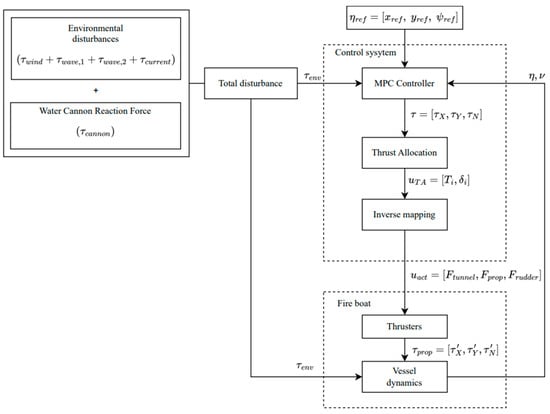
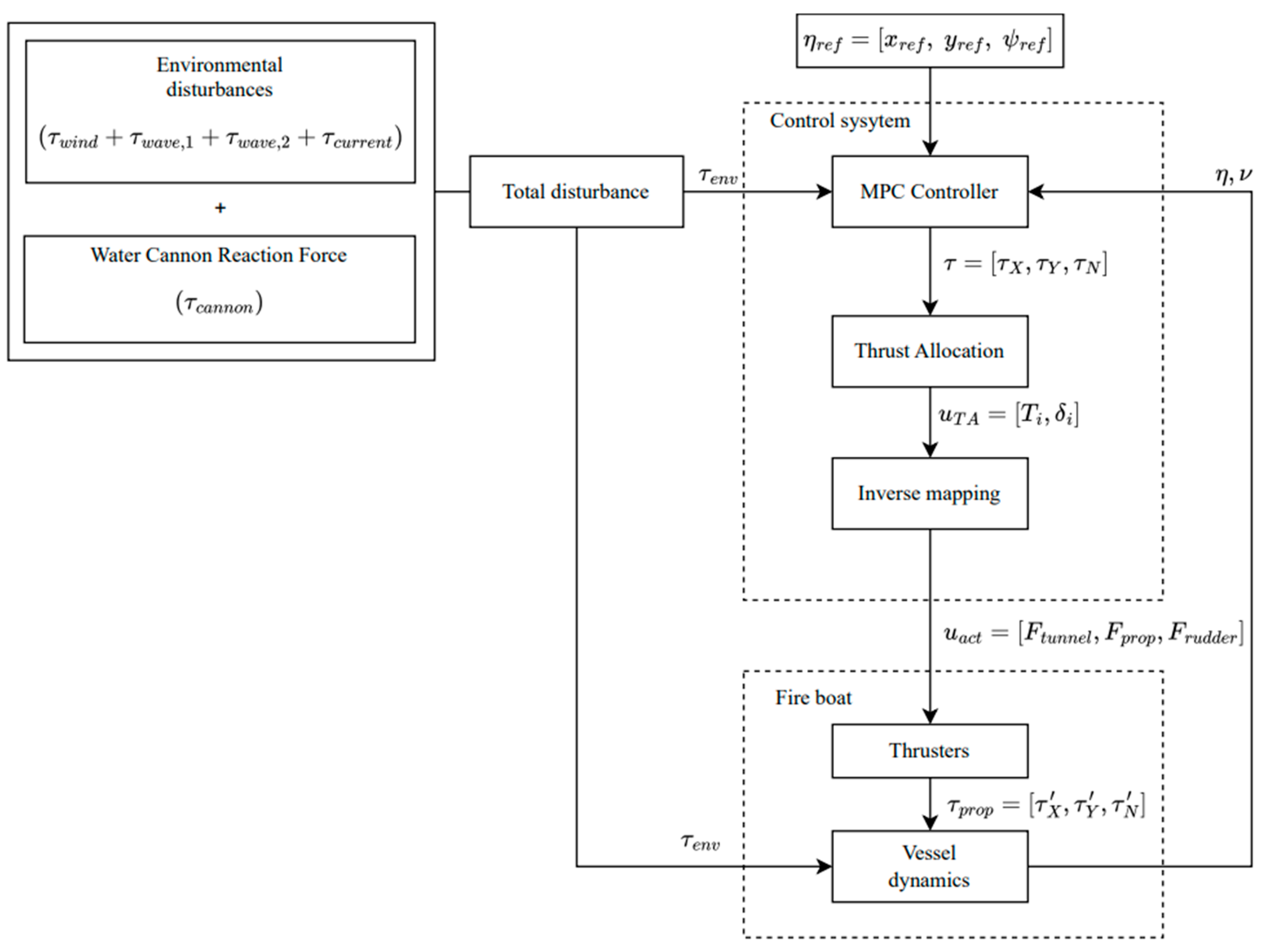
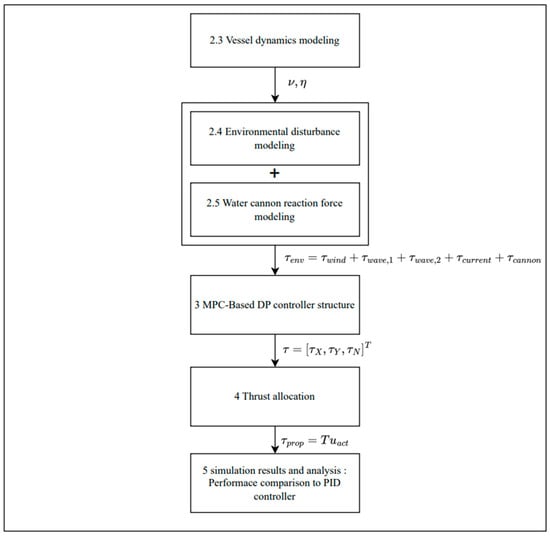
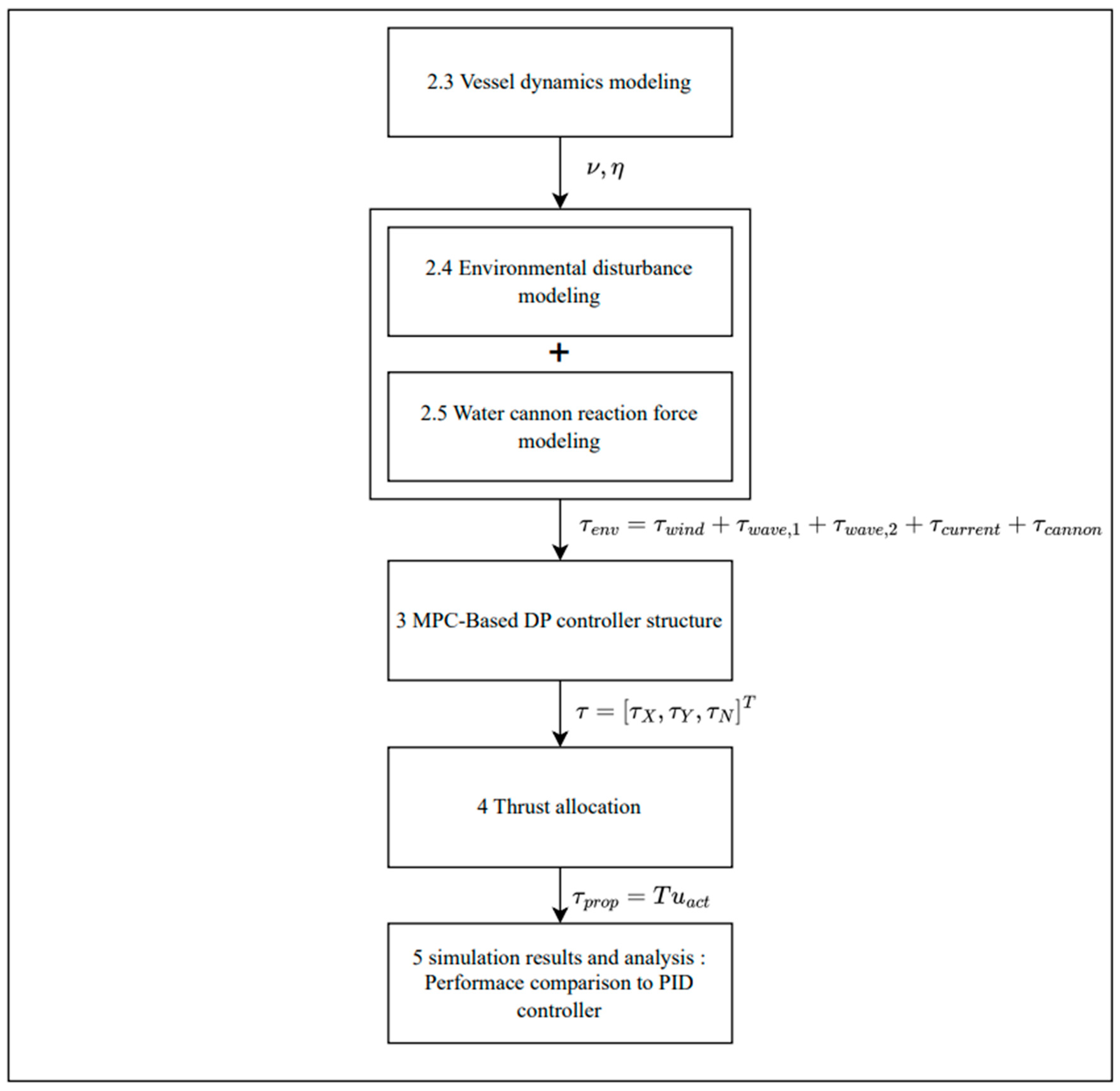
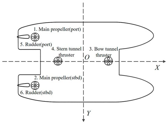
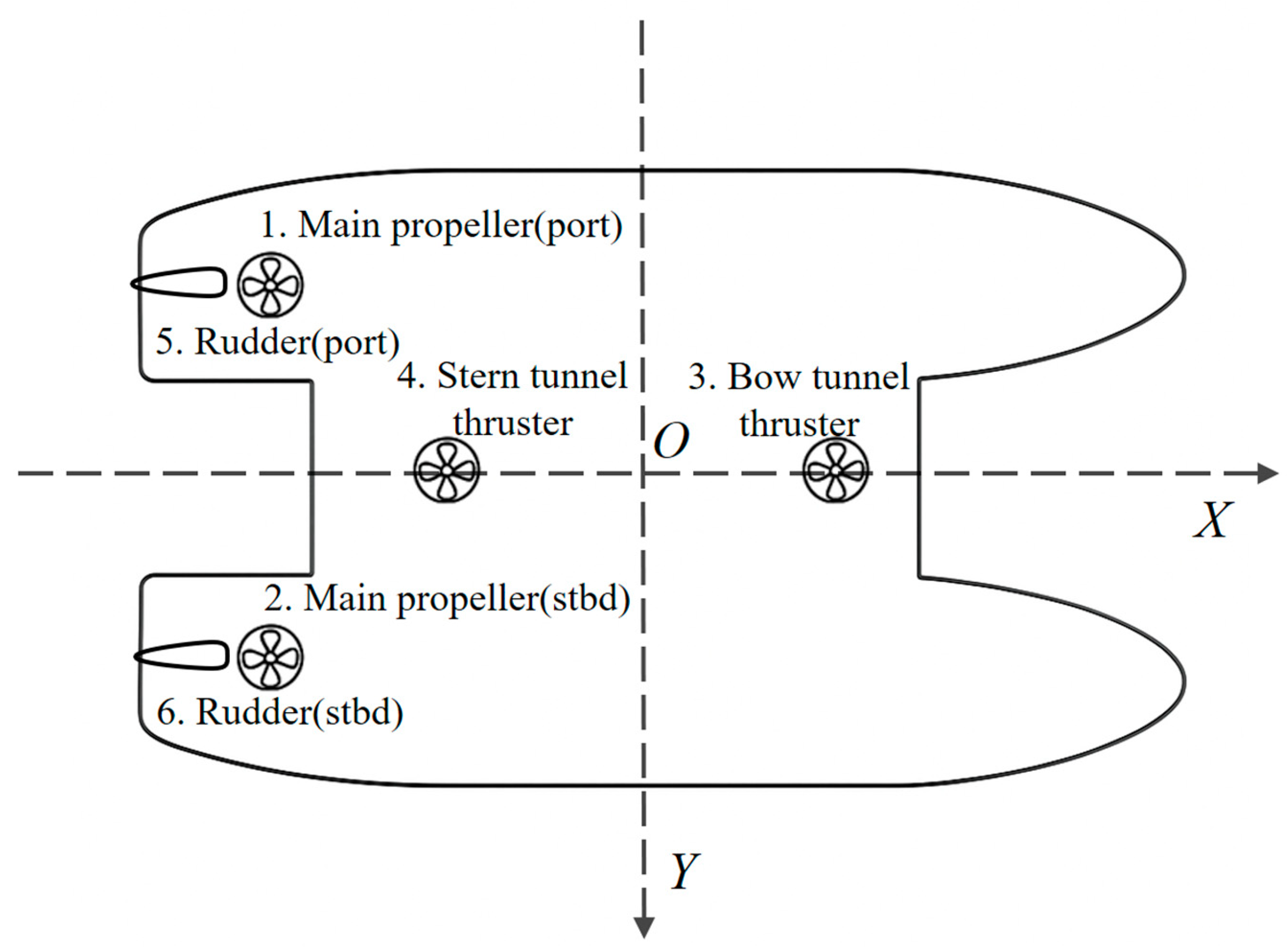
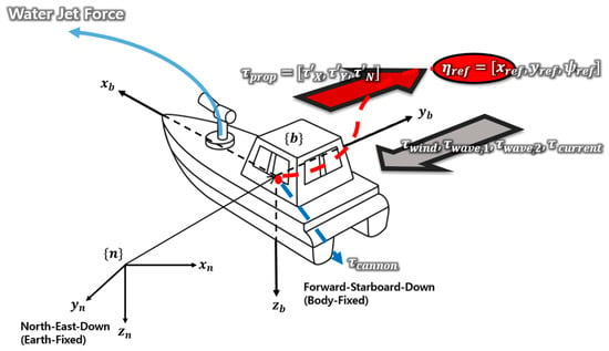
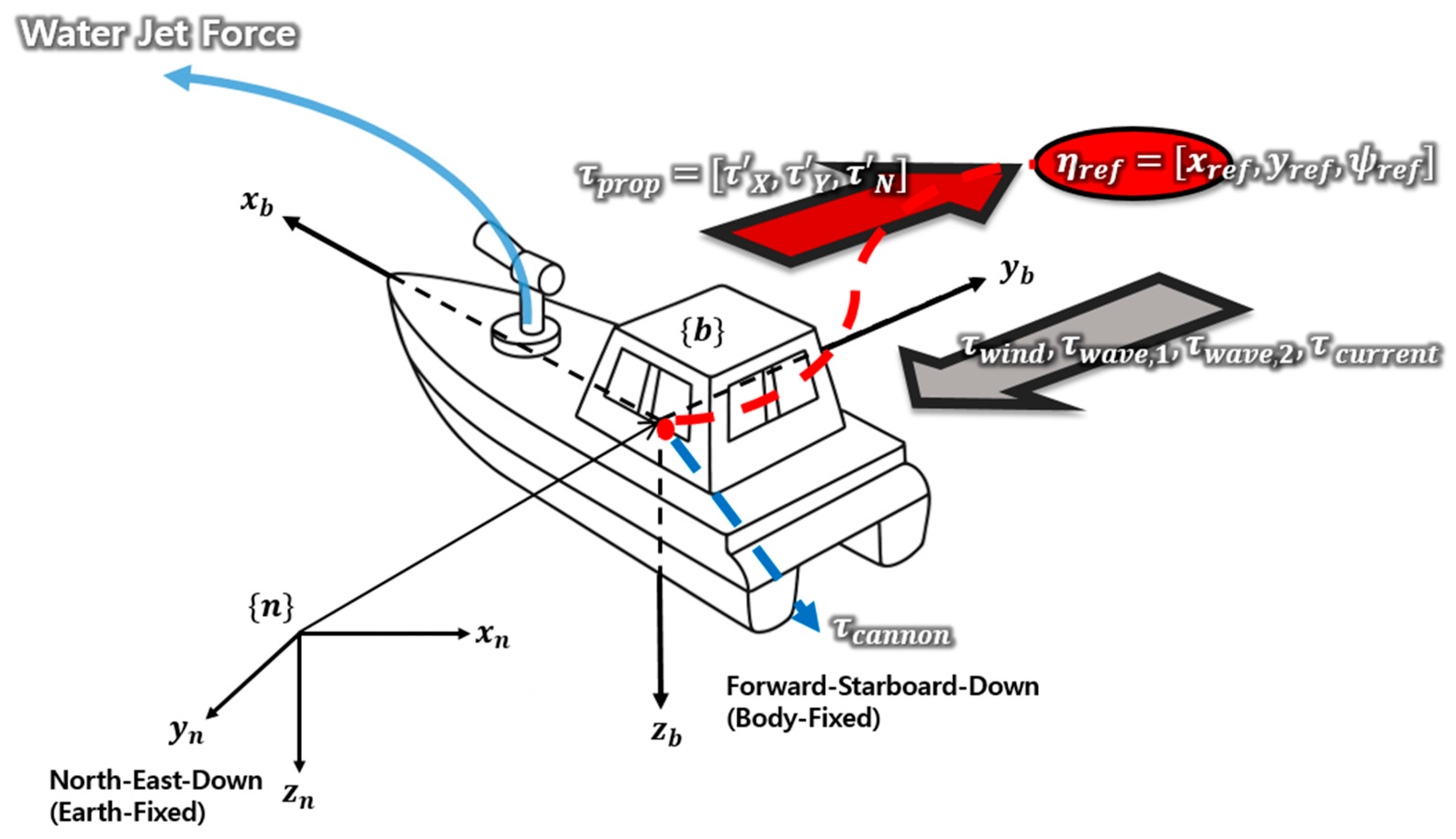
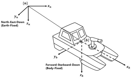
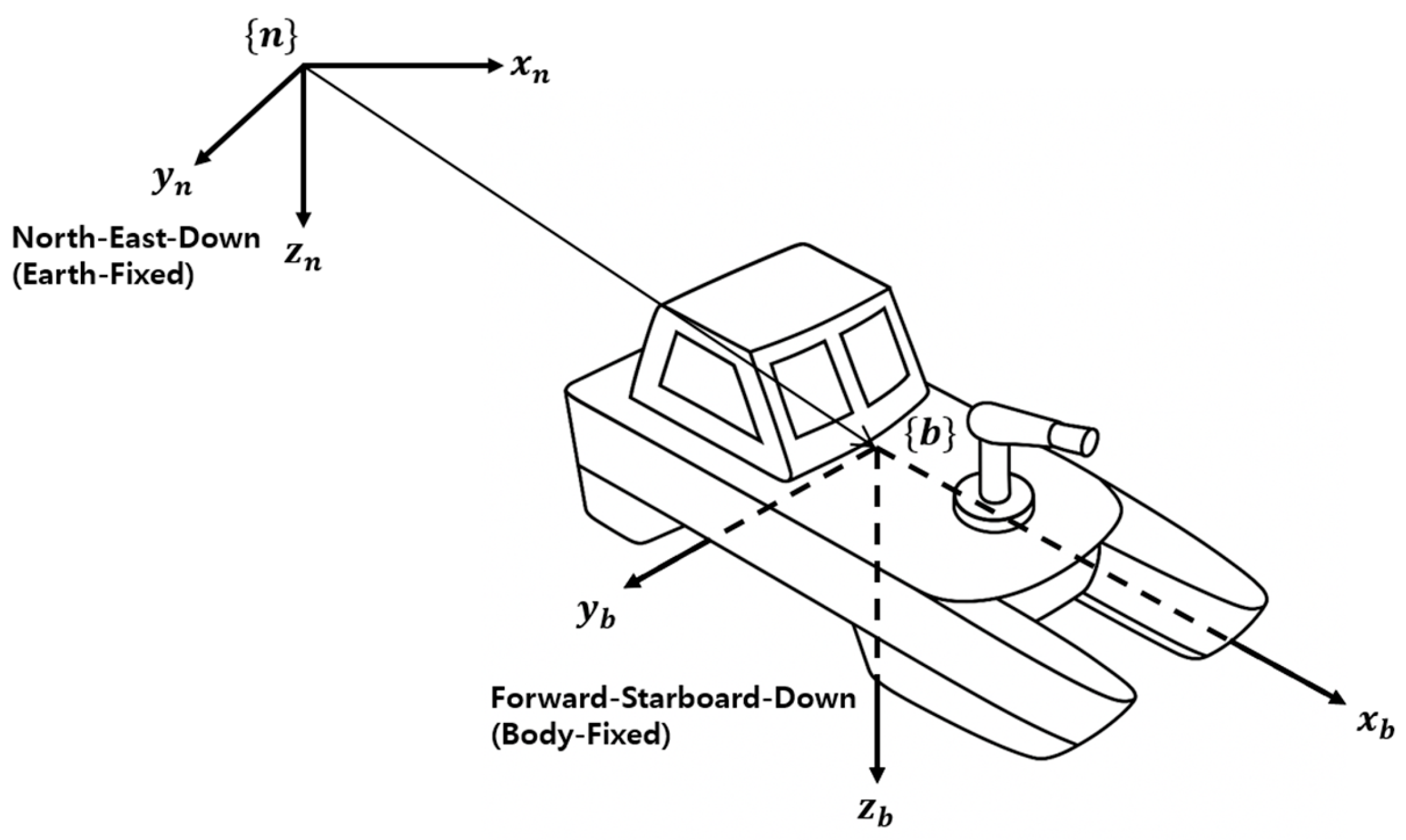
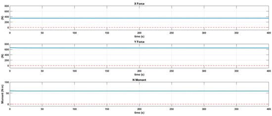
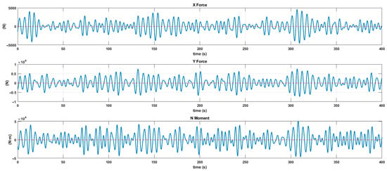
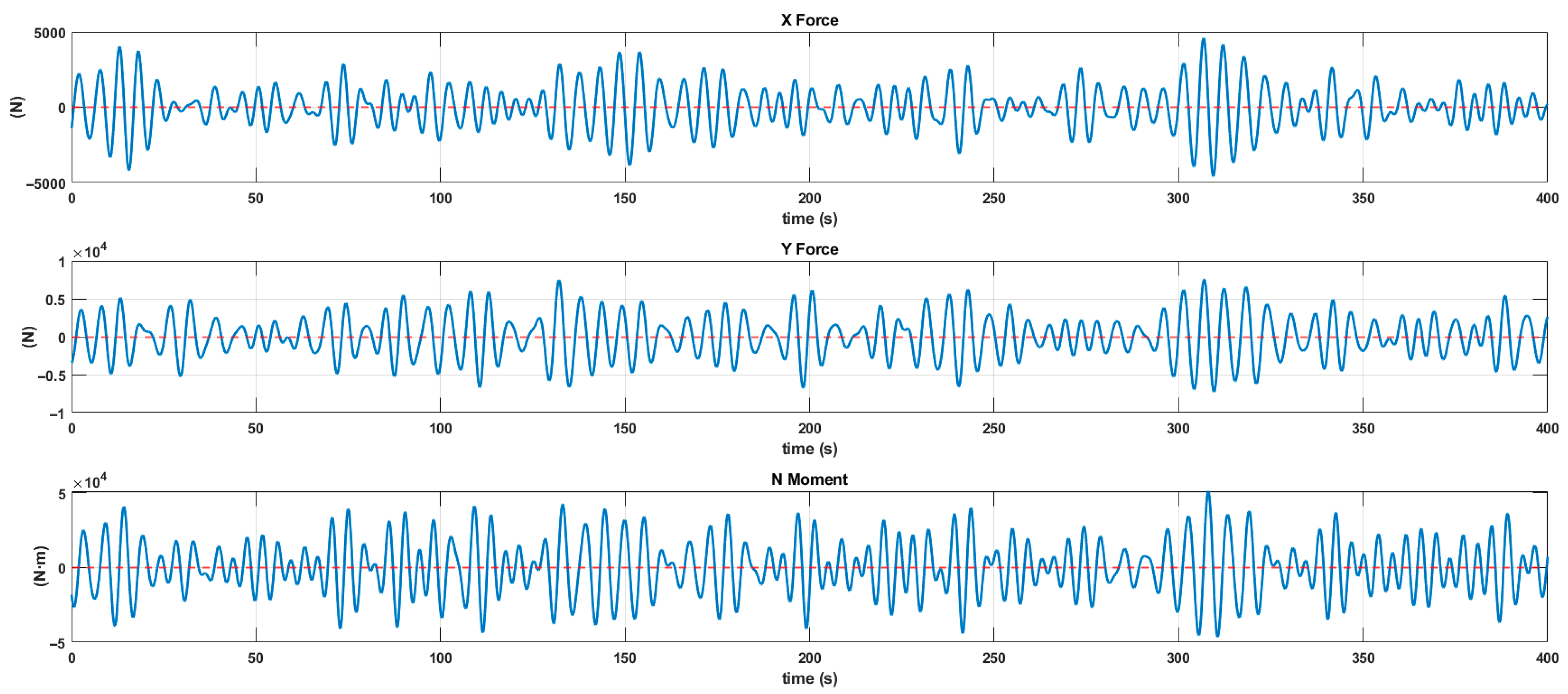
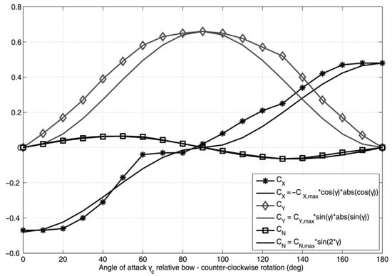
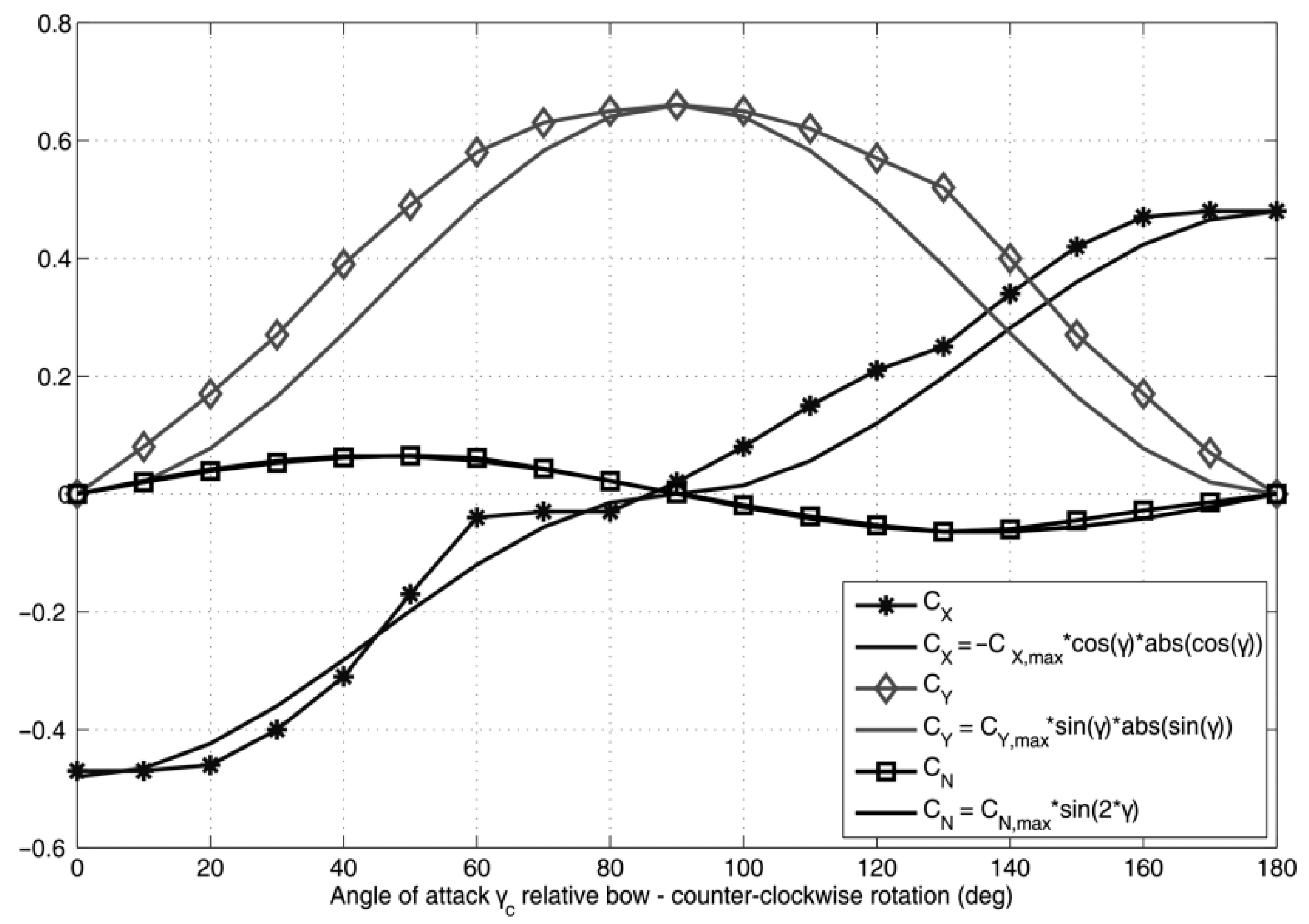
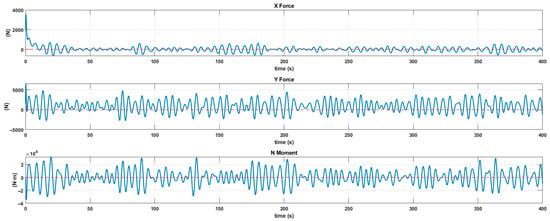
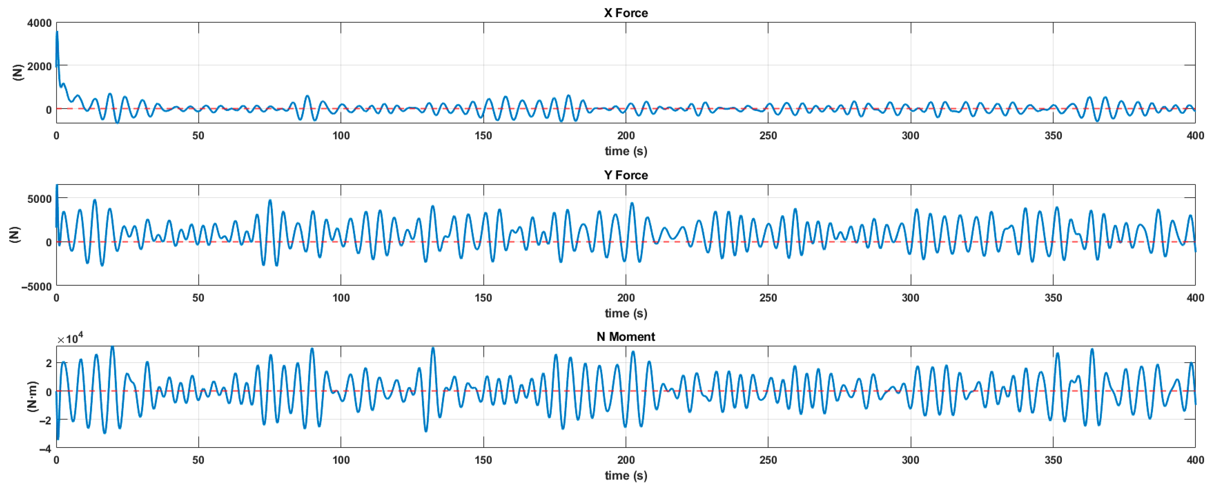
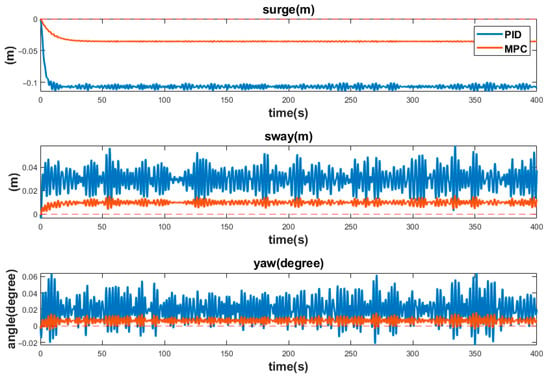
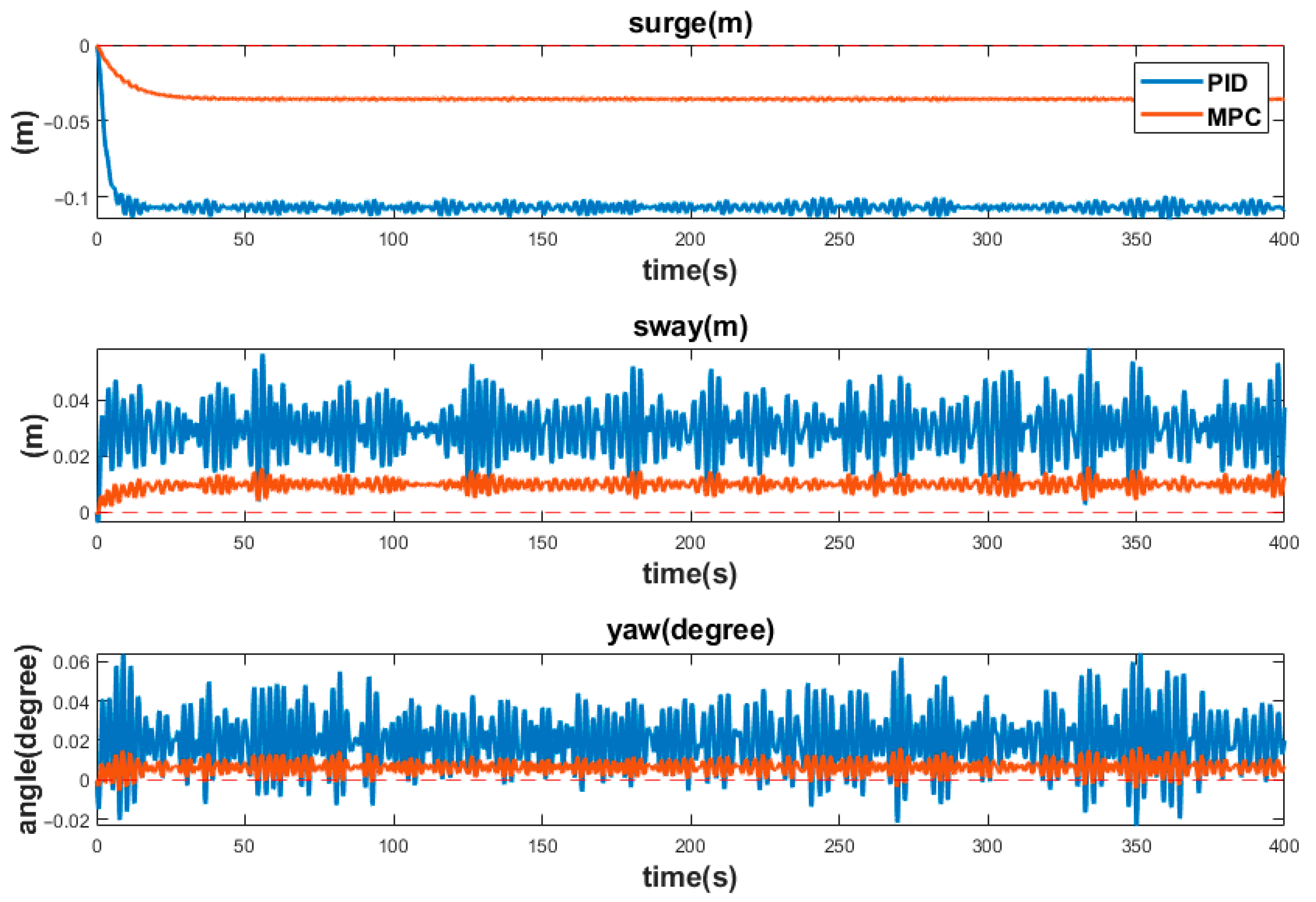
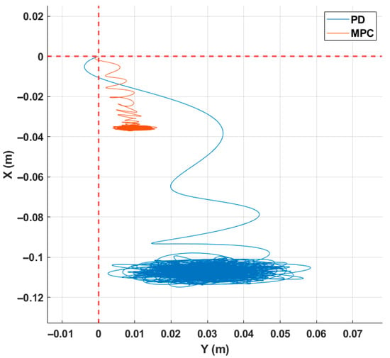
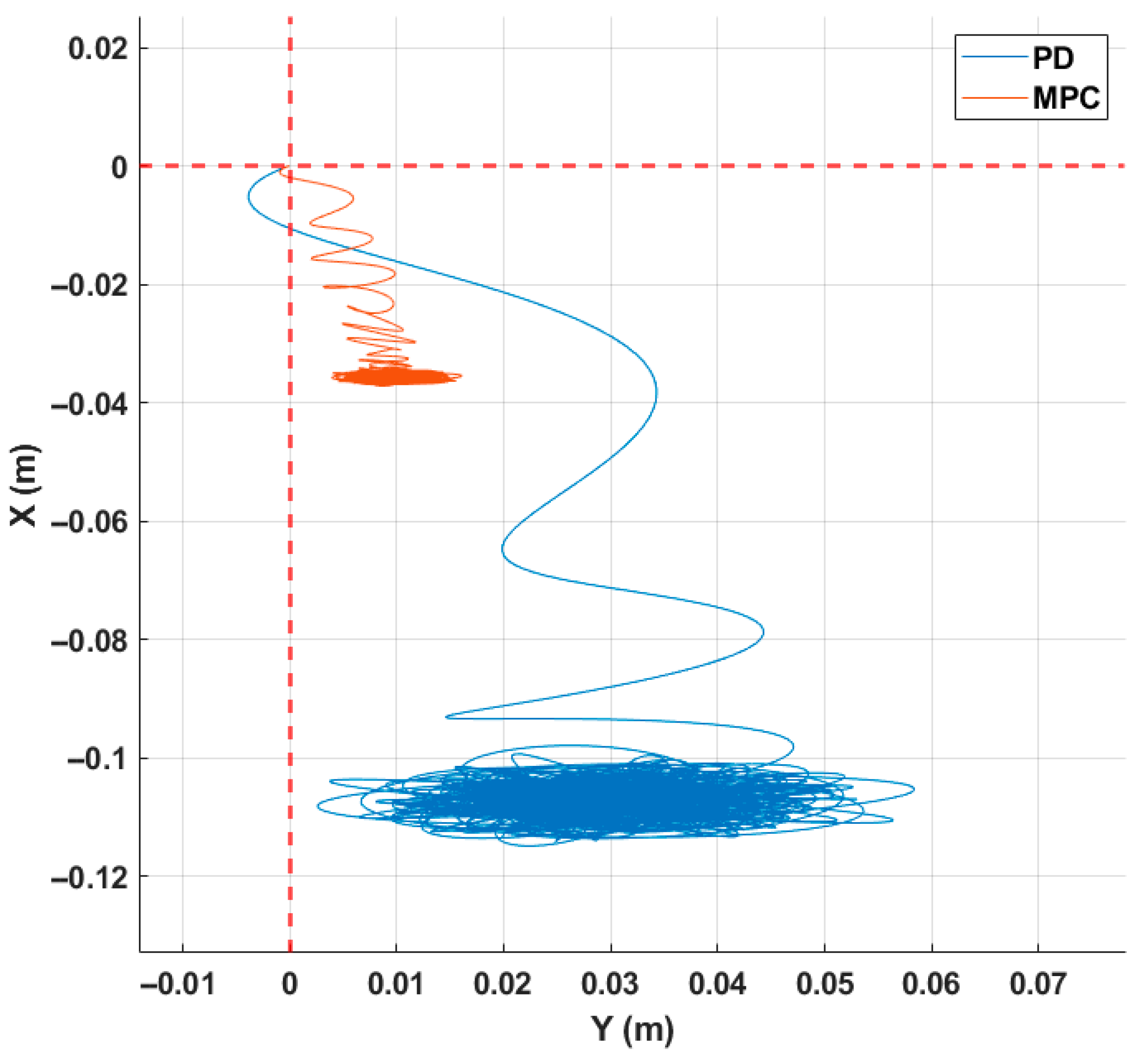
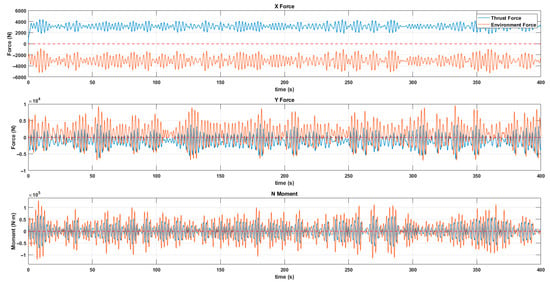
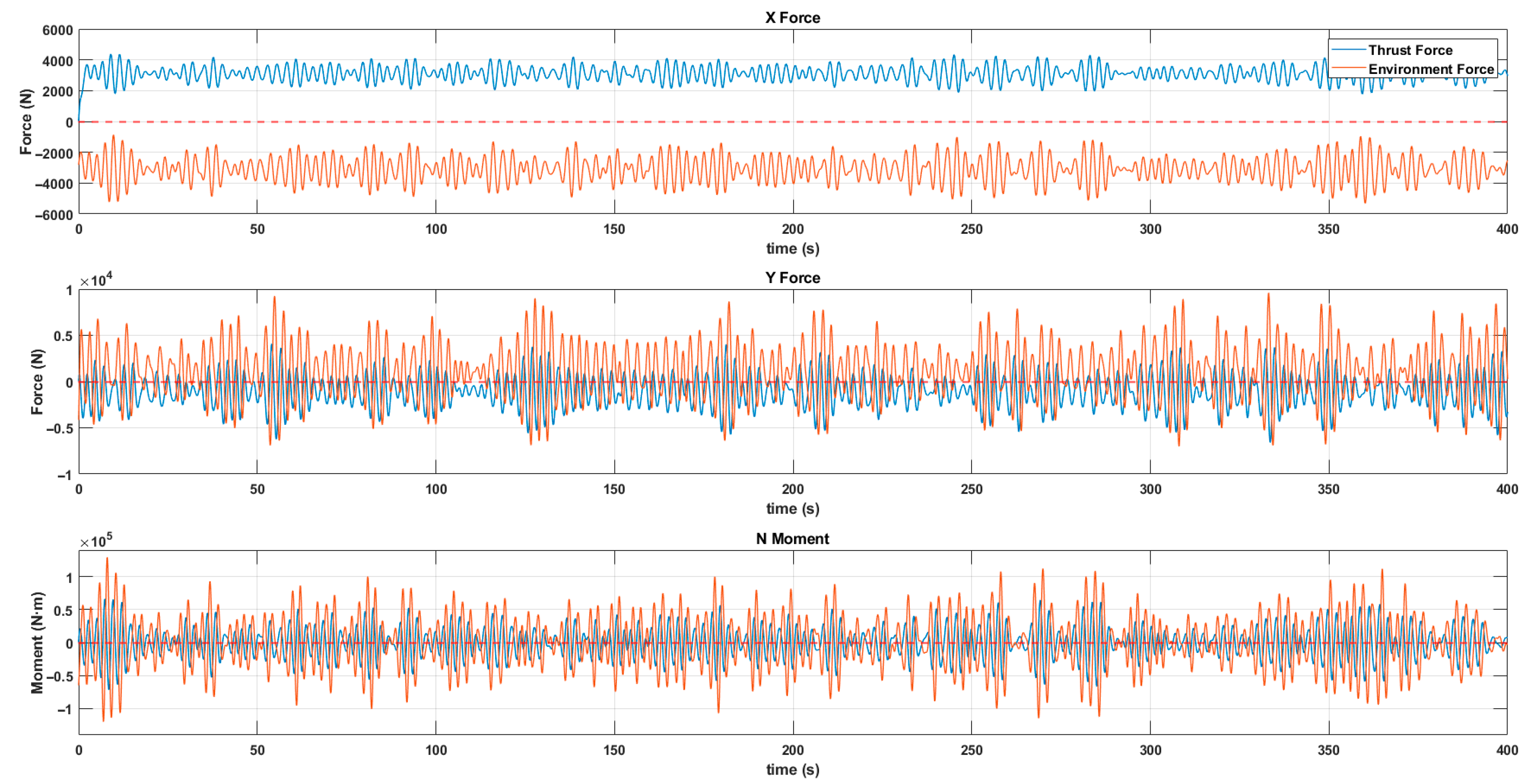
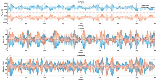
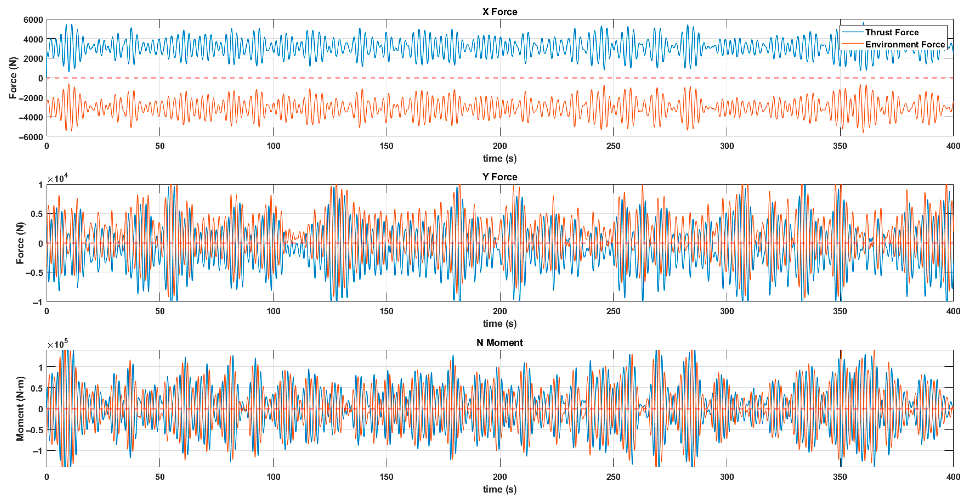
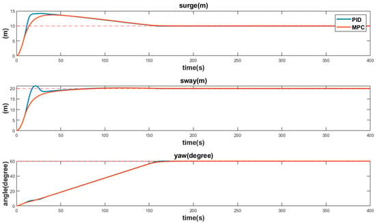
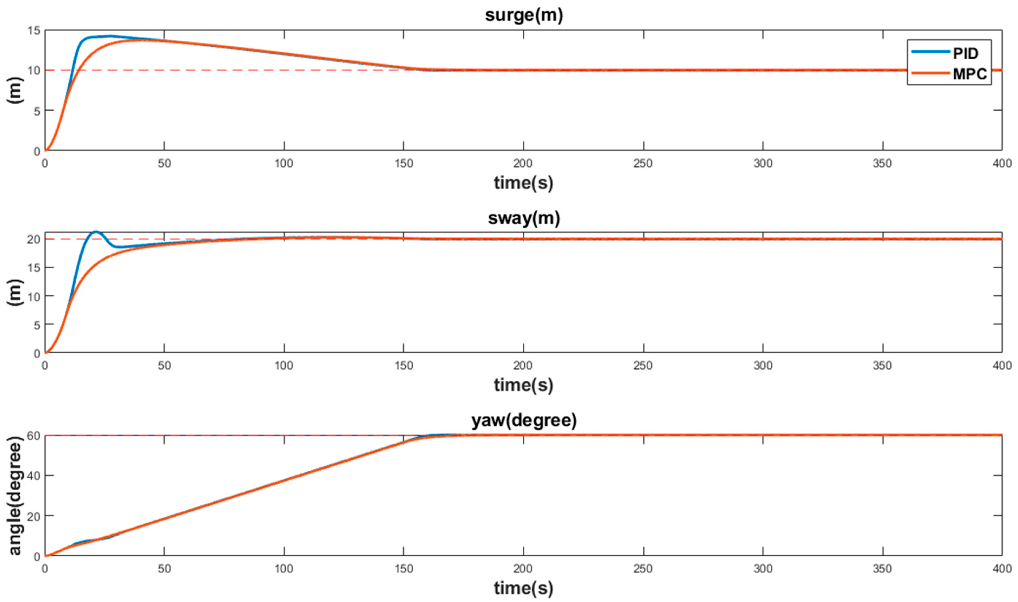
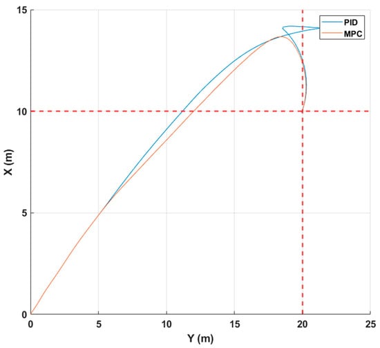
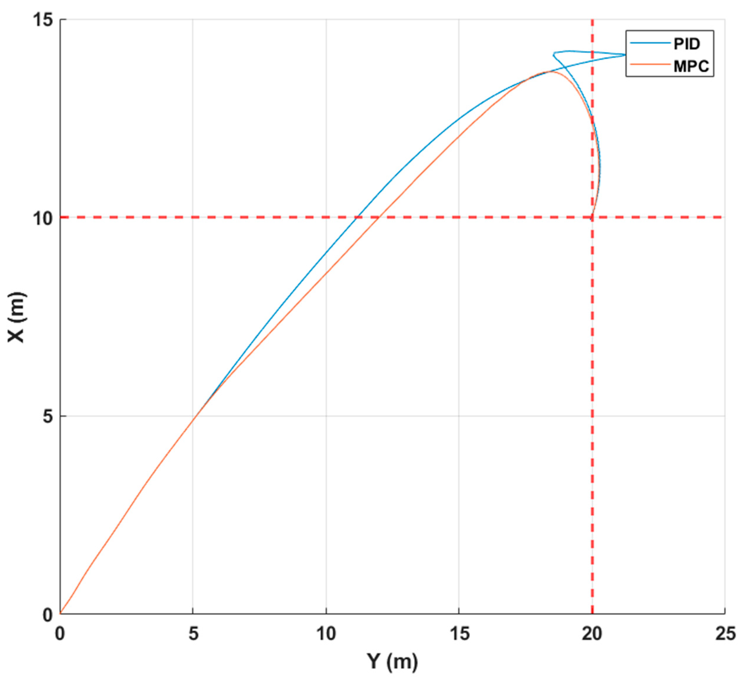
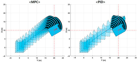
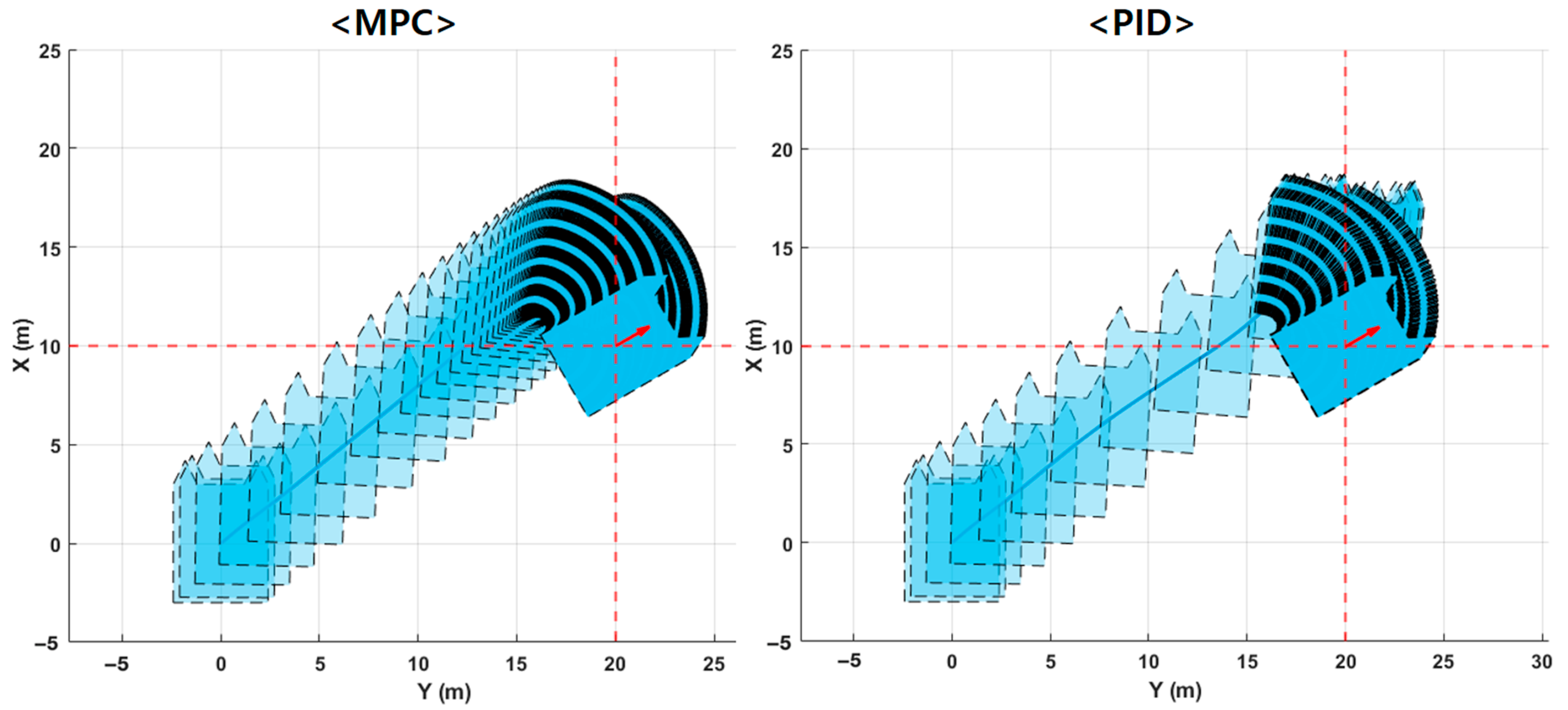
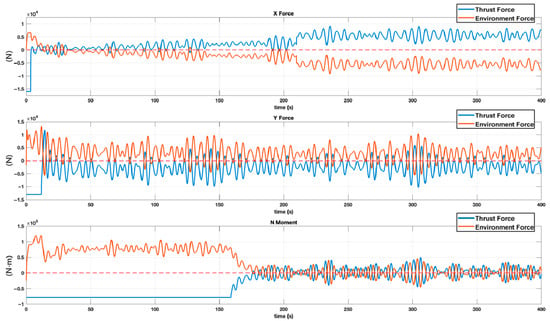
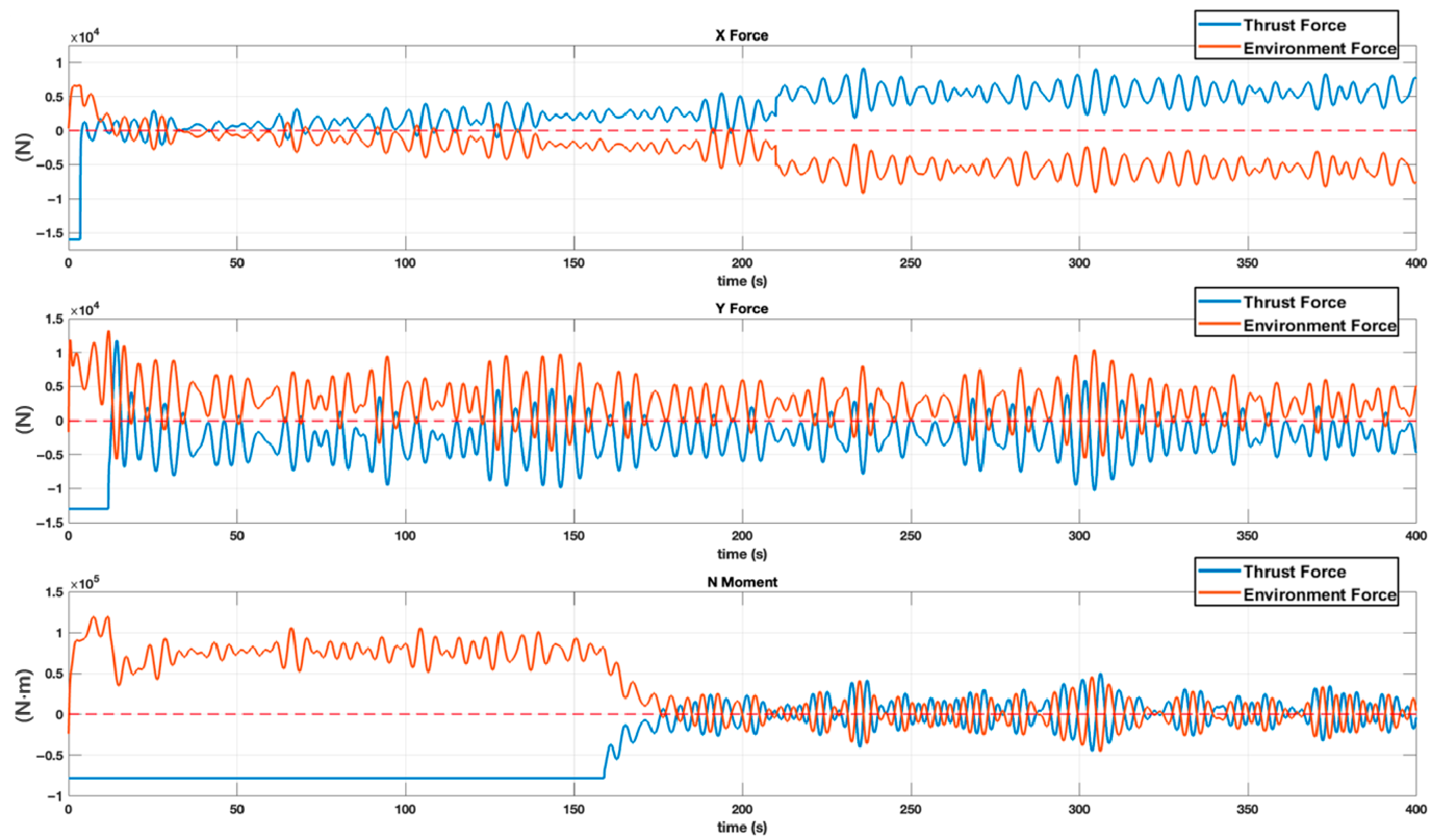
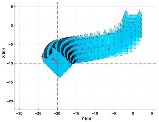
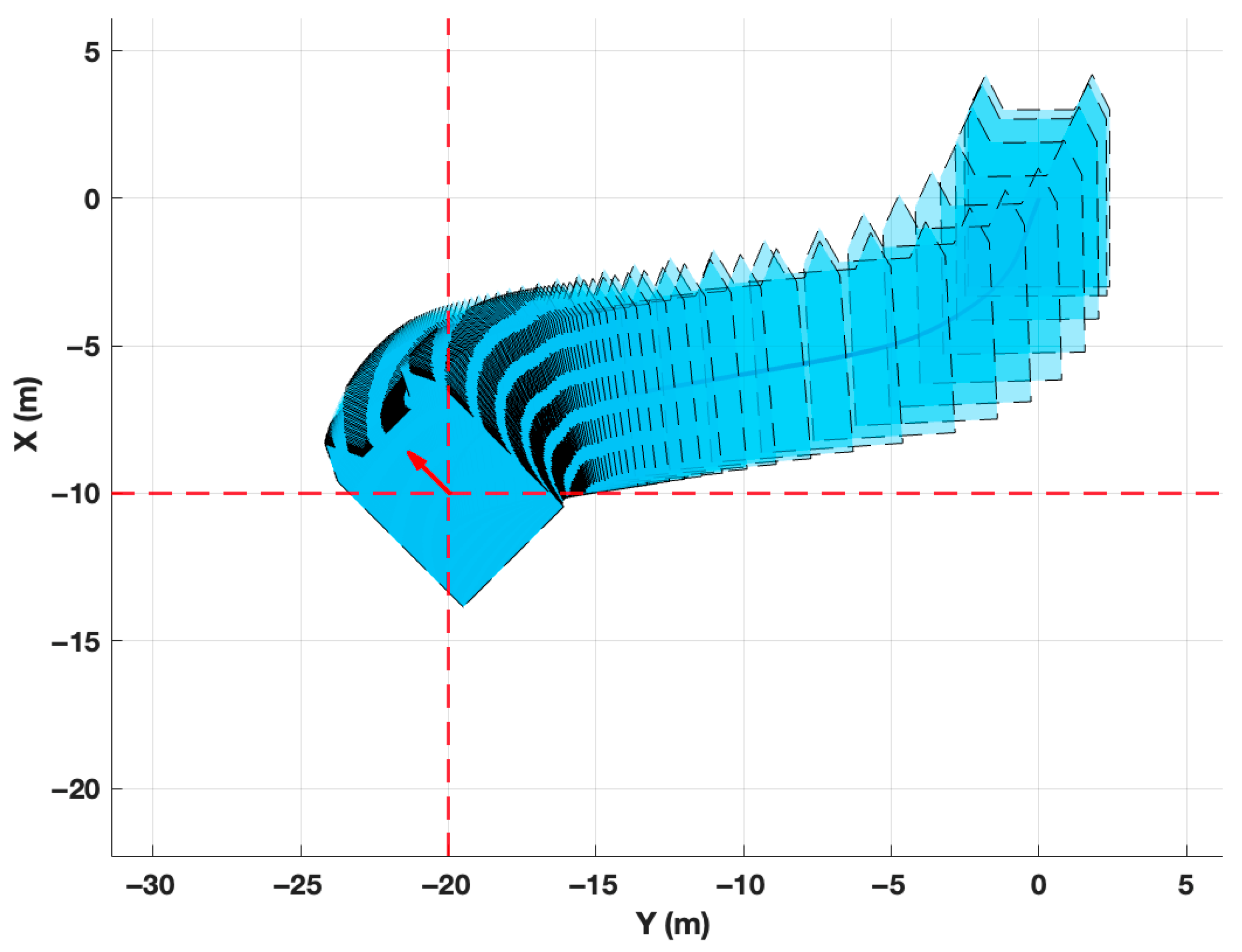
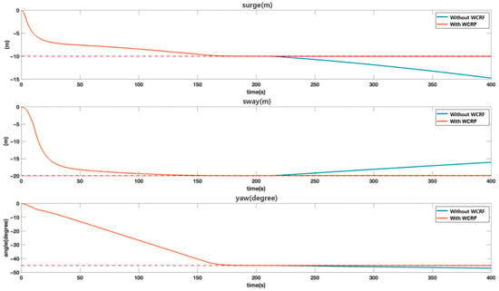
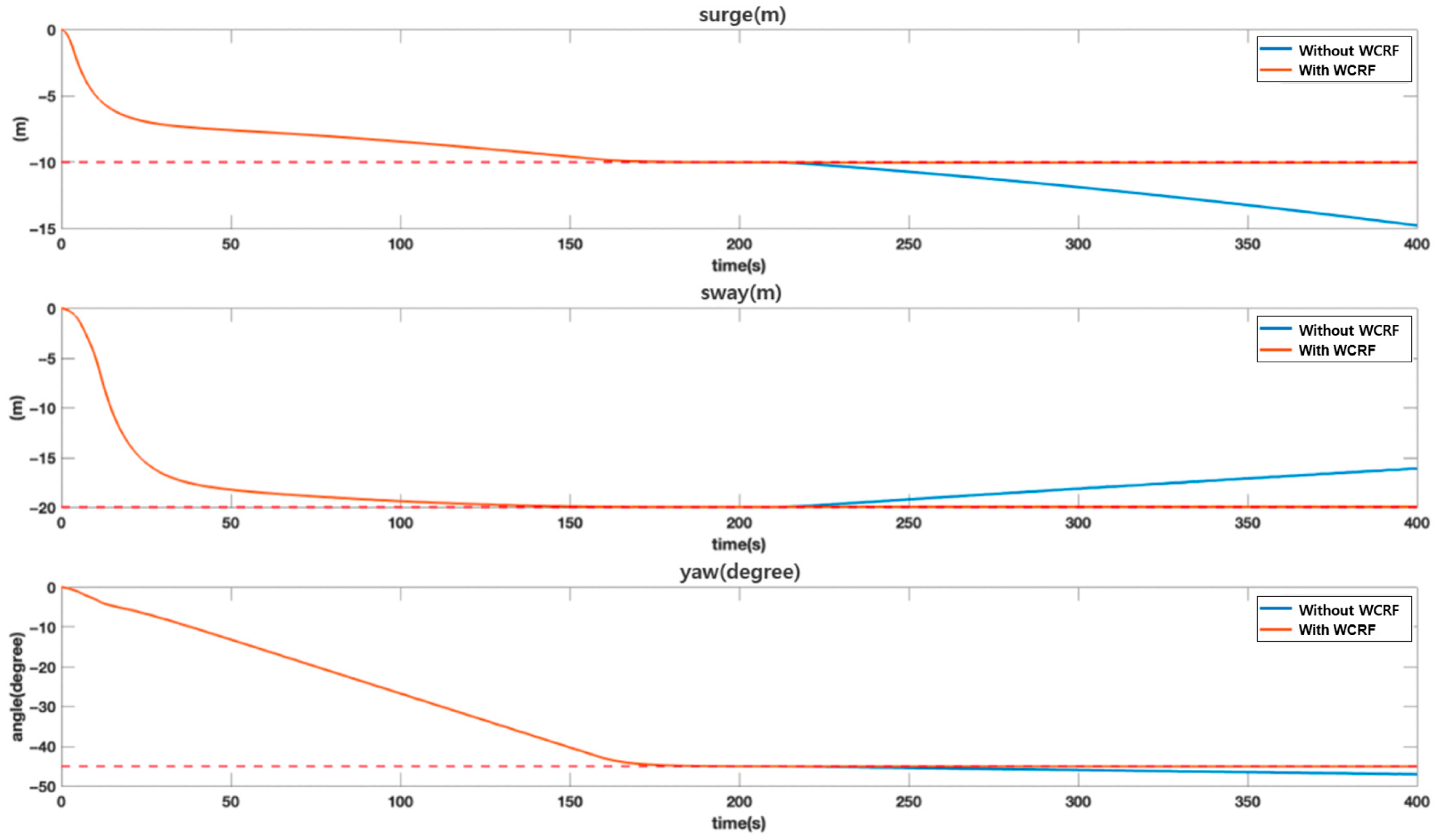
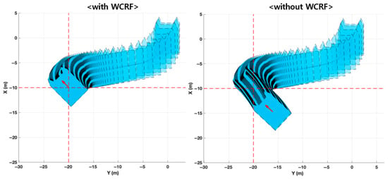
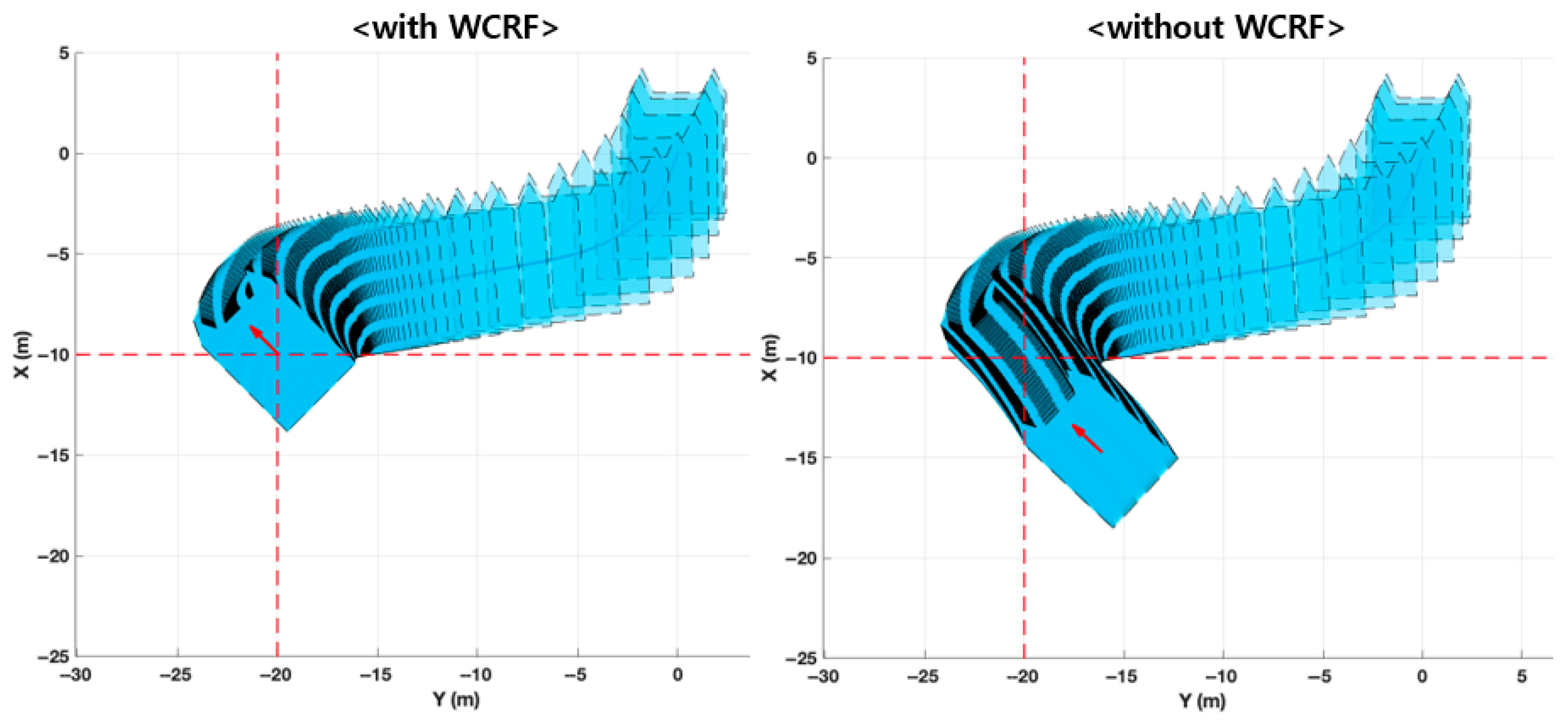
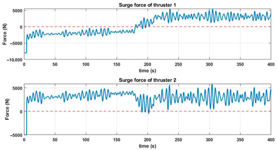
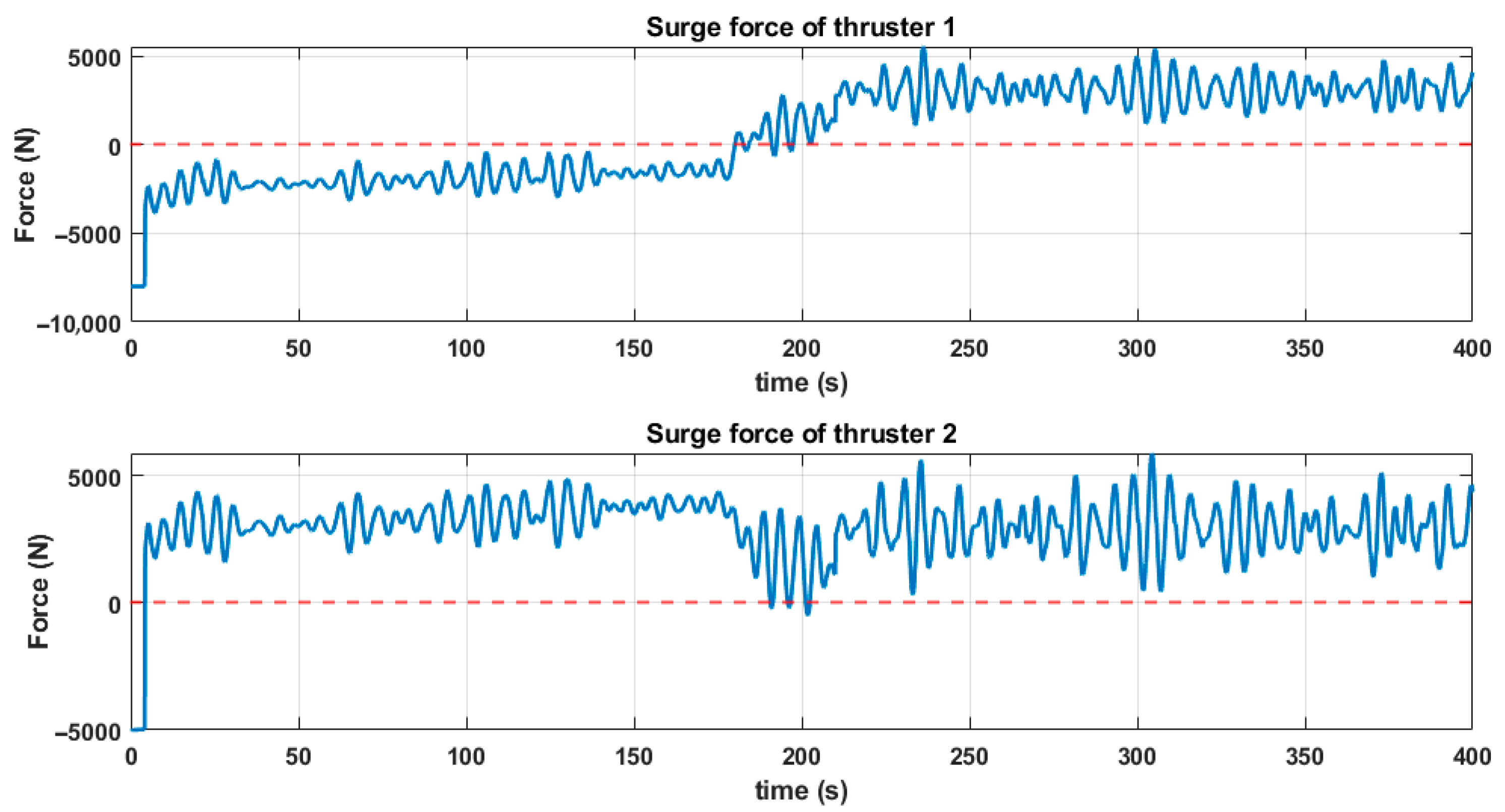
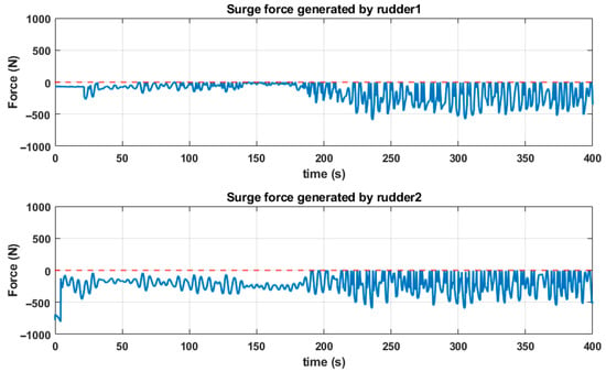
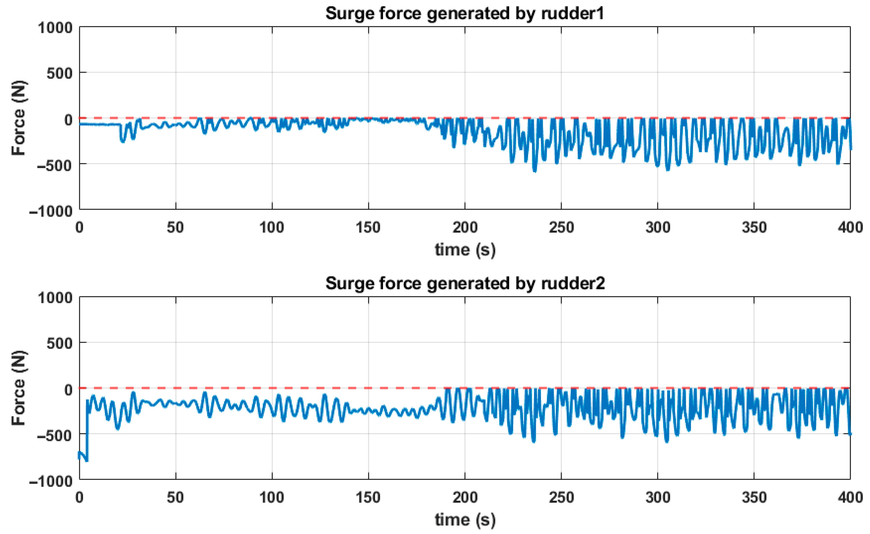
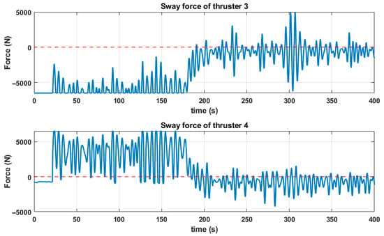
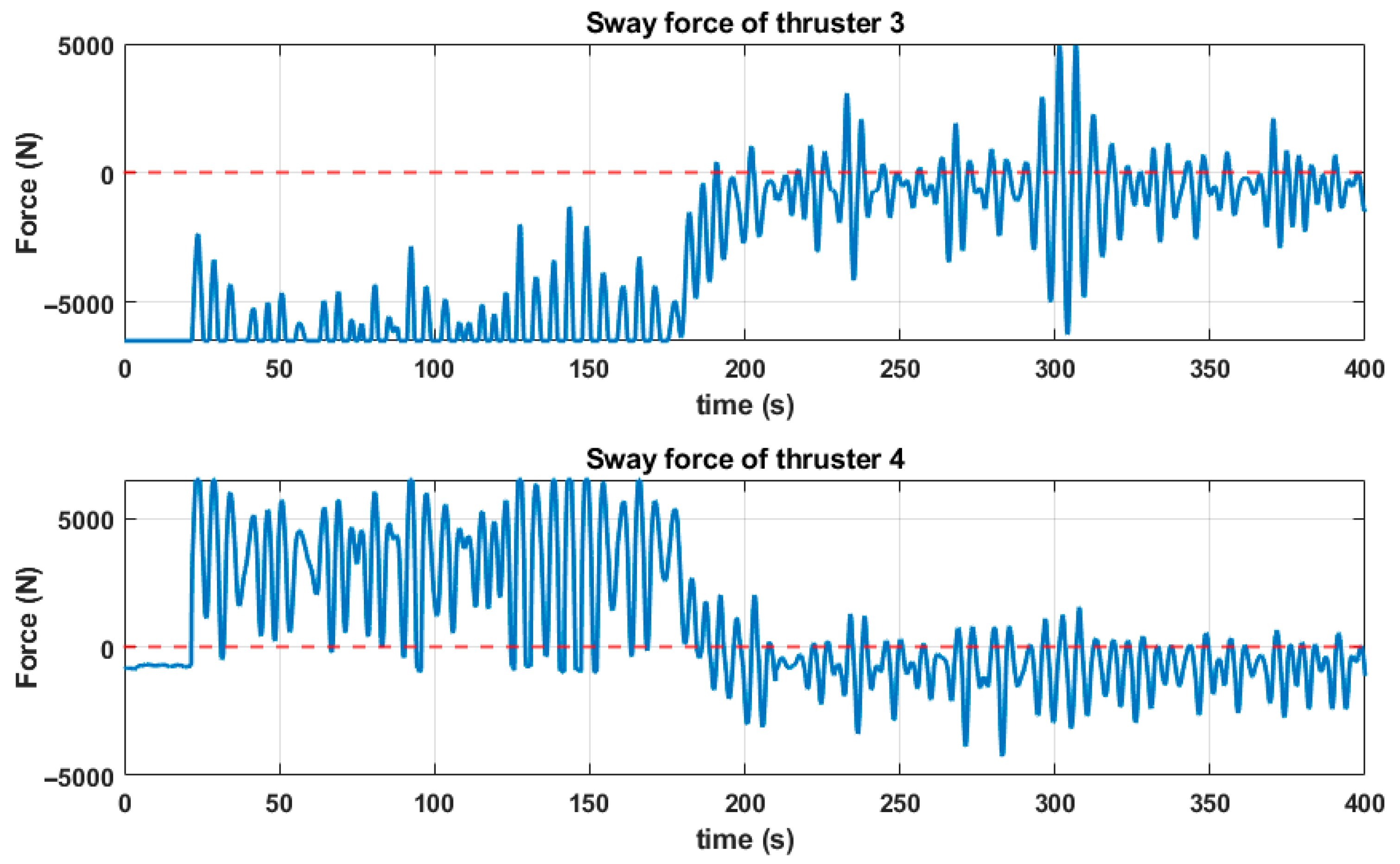
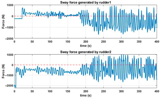
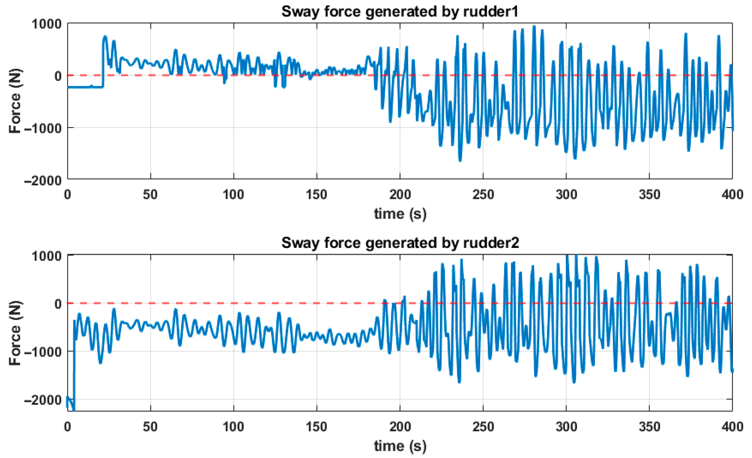
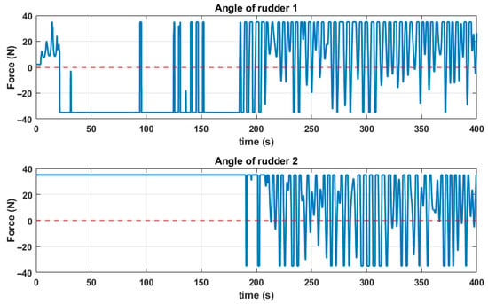
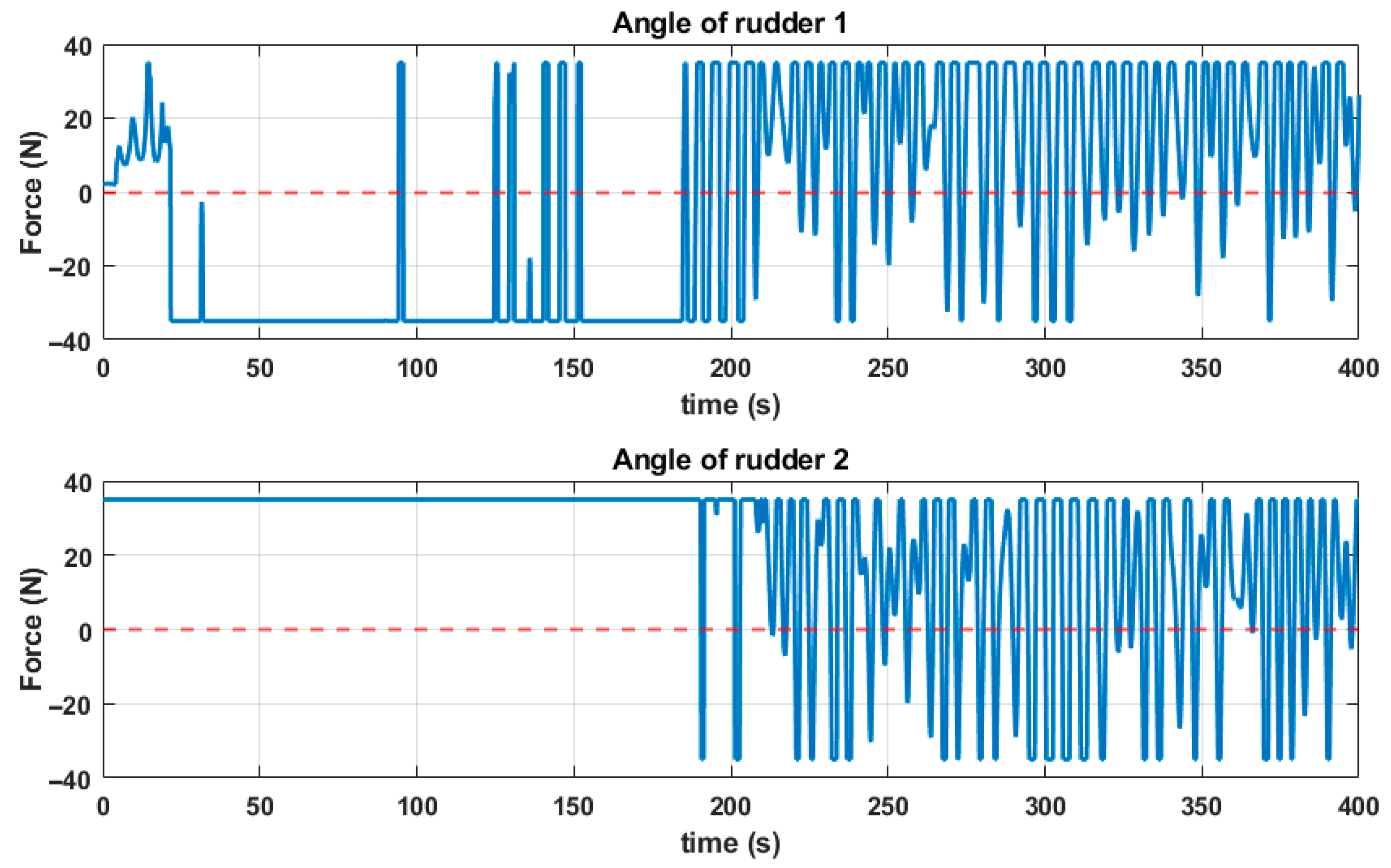
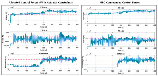
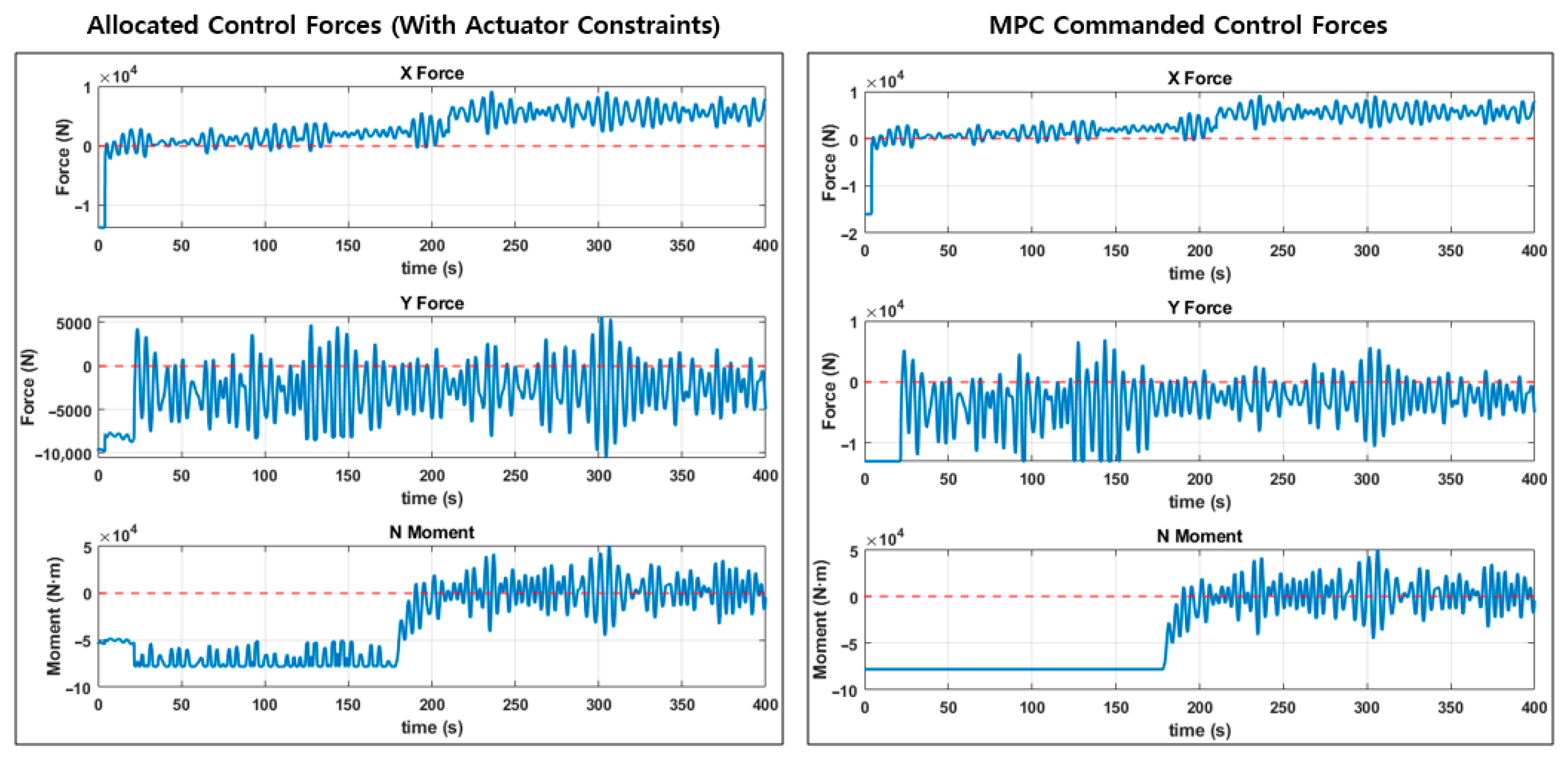
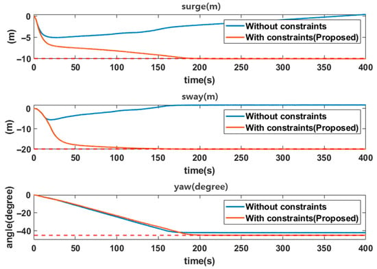
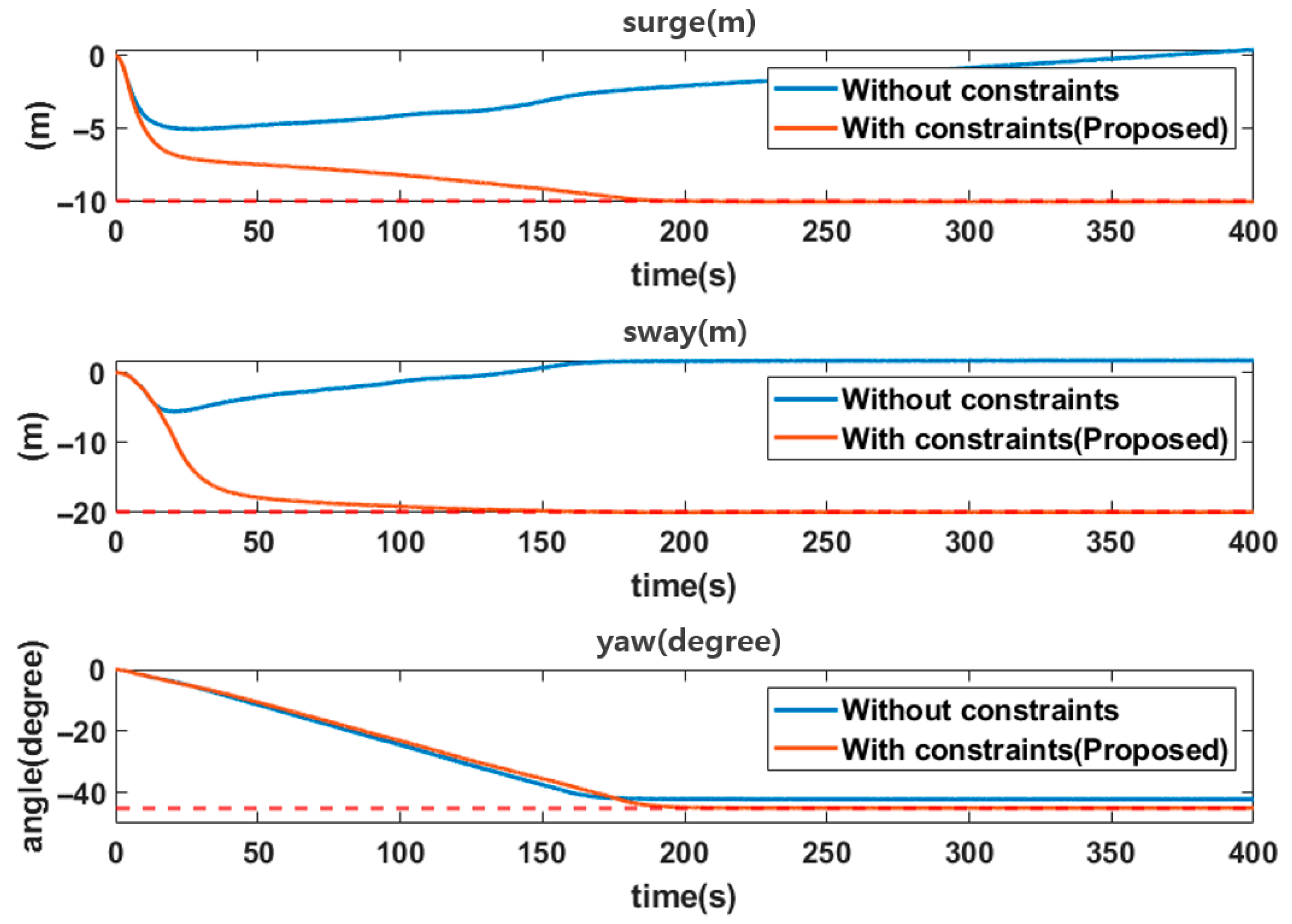
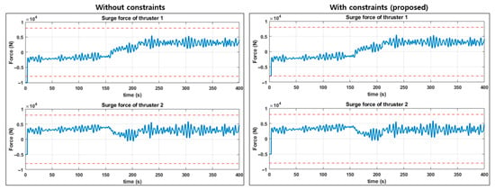
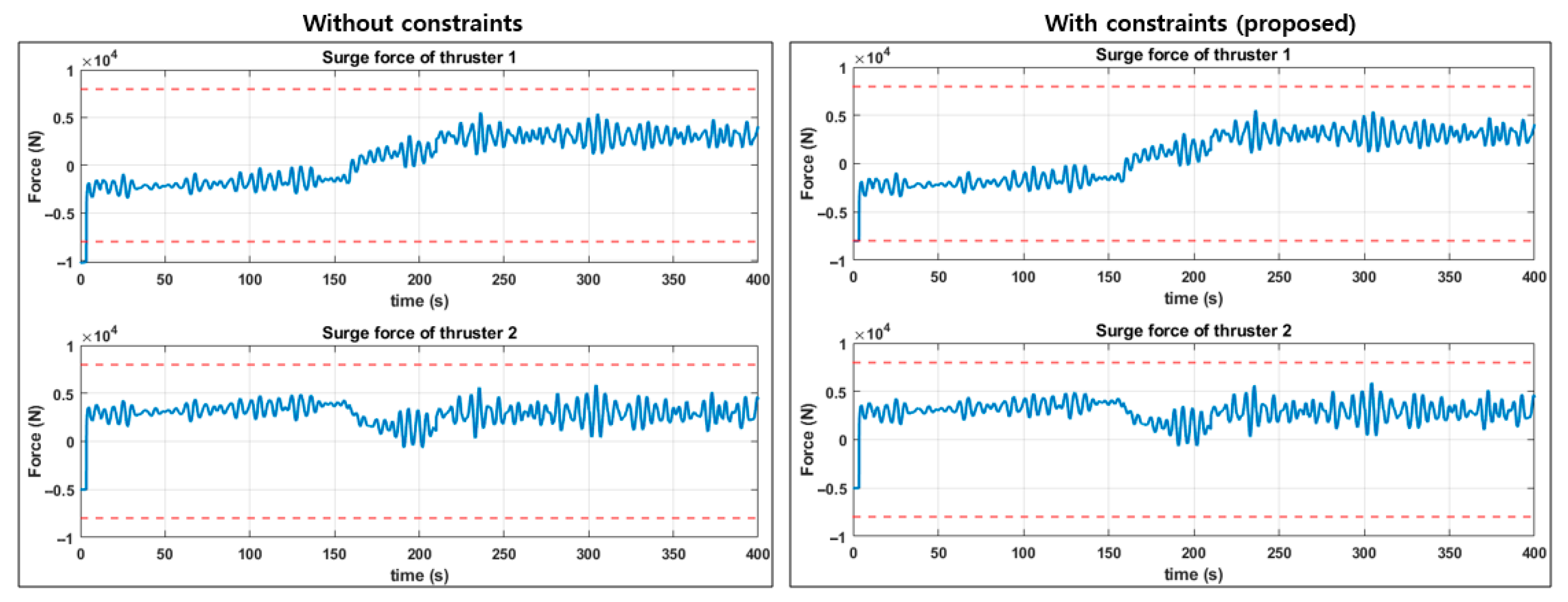
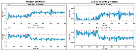
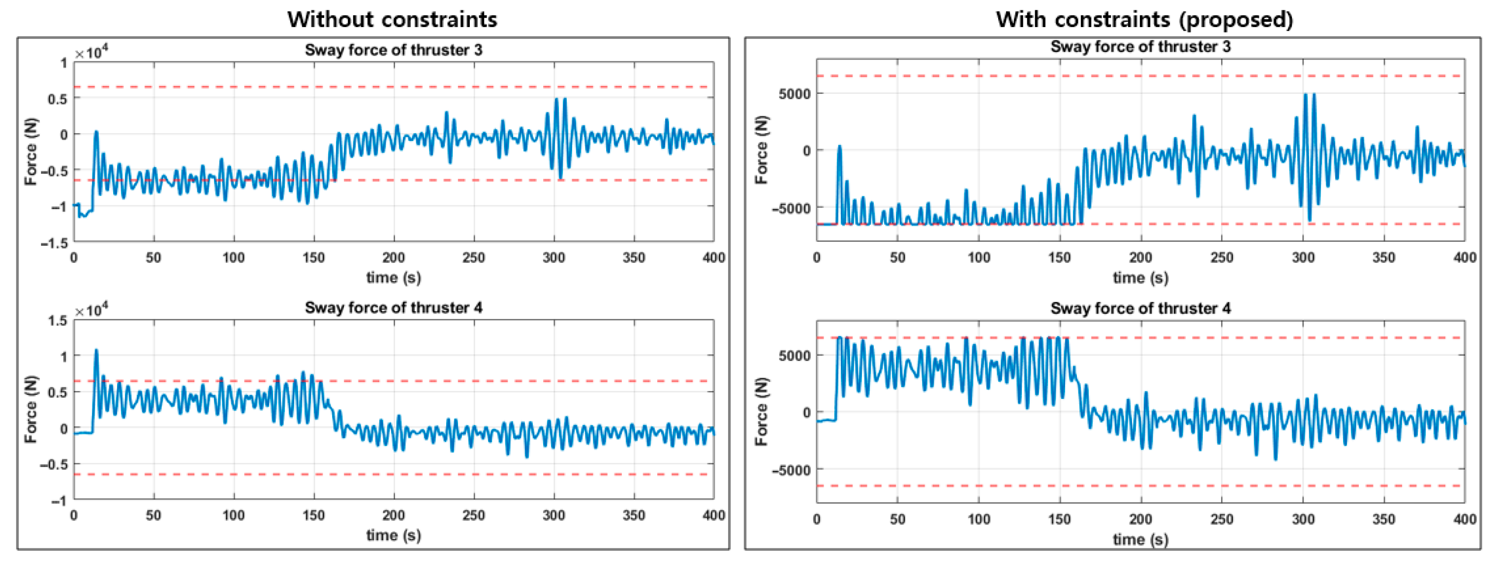

Disclaimer/Publisher’s Note: The statements, opinions and data contained in all publications are solely those of the individual author(s) and contributor(s) and not of MDPI and/or the editor(s). MDPI and/or the editor(s) disclaim responsibility for any injury to people or property resulting from any ideas, methods, instructions or products referred to in the content. |
© 2026 by the authors. Licensee MDPI, Basel, Switzerland. This article is an open access article distributed under the terms and conditions of the Creative Commons Attribution (CC BY) license.