


Abstract
Visual perception for autonomous carrier landing requires high stability and environmental adaptability. Under complex maritime conditions, such as nighttime, sea fog, and low visibility, visible images are easily affected by illumination changes and atmospheric scattering, resulting in reduced target contrast and weakened scene structures. Infrared images can provide relatively stable target information through thermal radiation differences between targets and backgrounds, but offer limited texture and fine-grained structural details. To address the difficulty of simultaneously preserving target saliency and scene structural integrity with a single modality, we propose CLSC-Fusion, an infrared–visible image fusion method for enhanced visual carrier-landing perception. Based on FusionGAN, CLSC-Fusion introduces an infrared gradient loss and a visible intensity loss to enhance the preservation of infrared salient information and visible details. An eight-neighborhood Laplacian operator with diagonal neighborhoods is further introduced into the gradient constraint to strengthen responses to multi-directional edges and texture variations. Meanwhile, the generator architecture is improved to enhance the representation of fusion features. Experiments on the TNO dataset show that CLSC-Fusion achieves competitive results in Spatial Frequency, Average Gradient, edge preservation, and PSNR, while maintaining high levels of Standard Deviation and SSIM. Ablation studies further verify the effectiveness of the proposed improvements. Case studies in visual carrier-landing scenarios demonstrate that CLSC-Fusion effectively integrates infrared target responses with structural information from flight decks, islands, and sea–sky backgrounds, providing more complete visual information for carrier-based aircraft perception under complex environments.
Keywords:
visual carrier landing; infrared–visible image fusion; visual perception enhancement; eight-neighborhood Laplacian operator MSC:
68U10; 68T07; 68T45
1. Introduction
Carrier landing is one of the most critical and challenging phases in the operational cycle of carrier-based aircraft. Landing performance directly affects the safety of both the aircraft and the carrier, as well as mission efficiency. During landing, a carrier-based aircraft must follow a prescribed approach path, glide angle, speed, and flight attitude to gradually approach the flight deck. Within a very short distance, the tailhook engages the arresting cable to achieve rapid deceleration and a safe stop, as illustrated in Figure 1 [1]. Compared with land-based aircraft landing, carrier landing features a short landing area, small allowable errors, high aircraft speed, complex deck motion, and strong interference from the marine environment. Its accident rate is approximately 3–6 times higher than that of land-based aircraft, while the accident rate at night is about twice that in daytime. Moreover, modern combat operations are often conducted at night, when time constraints and adverse weather conditions may provide favorable operational opportunities. Therefore, modern warfare requires carrier-based aircraft to possess all-weather operational capability.
Figure 1.
Schematic of the final approach phase of carrier landing and its key observation points. Start, Middle, Close, and Ramp represent four key positions along the final glide path. This phase lasts approximately 15–17 s. Adapted from [1].
To support all-weather carrier landing, the U.S. Navy developed the radar-based All-Weather Carrier Landing System (AWCLS) in the 1970s. The Joint Precision Approach and Landing System (JPALS) was subsequently developed as a satellite-based precision approach and landing system employing differential GPS techniques, including shipboard relative GPS for shipboard approach and landing [2]. However, visual landing is still required under electromagnetic interference or satellite denial, which greatly increases the difficulty of landing at night or under adverse weather conditions, as shown in Figure 2. In addition, with the development of carrier-based unmanned aerial vehicles, the demand for autonomous carrier landing has continued to increase.
Figure 2.
Carrier-based aviation operations of the U.S. Navy under complex environmental conditions: (a) nighttime carrier landing operations aboard USS Ronald Reagan in the Indian Ocean [3]; (b) carrier-based aviation operations aboard USS George H. W. Bush under dense fog conditions in the Atlantic Ocean [4]; (c) USS Carl Vinson encountering a sandstorm in the Arabian Sea [5].
As a passive sensing modality, vision can directly capture key environmental elements, including the flight deck, landing area, glide-path indicator lights, arresting cables, and ship attitude. Unlike satellite navigation and radio-based guidance systems, vision-based perception does not rely on external radio-frequency navigation signals and can provide an independent source of environmental information for terminal landing. It is therefore less susceptible to electromagnetic interference and can complement conventional navigation and guidance systems. Consequently, vision-based assisted and autonomous landing has gradually become an important research direction for carrier-based aircraft recovery.
However, visual perception for carrier landing still faces several challenges. First, during the terminal landing stage, the relative distance between the aircraft and the carrier deck decreases rapidly, while the field of view, target scale, and viewing angle continuously change. As a result, deck structures and key landmarks in the image exhibit significant scale variation and perspective distortion. Second, sea fog, rain and snow, nighttime low illumination, strong deck reflections, and complex sea–sky backgrounds can substantially degrade visible-image quality, causing blurred or broken deck edges, runway centerlines, and landing-area markings, as well as insufficient contrast. Third, although infrared images can highlight lights, heat sources, and target contours under low illumination and complex weather conditions, they provide relatively limited texture details and structural edge information, making it difficult to independently describe complete deck spatial structures. In addition, the carrier deck exhibits clear oblique perspective structures from the landing viewpoint. Key visual elements such as deck edges, runway lines, and landing-area contours are important for landing perception, but can be easily disturbed by sea-surface textures, deck reflections, and low-contrast regions under complex backgrounds. Therefore, obtaining stable visual inputs with both target saliency and structural distinguishability at the terminal landing stage remains a key problem in visual carrier-landing perception.
Infrared and visible image fusion provides an effective way to address these problems. Visible images can better preserve deck textures, edge contours, runway centerlines, and spatial structural information, but are sensitive to illumination changes and complex weather conditions. Infrared images can highlight thermal targets, lights, and high-temperature deck regions, providing stronger target saliency at night and under low-visibility conditions, but offer relatively limited texture details and structural edge information. By fusing infrared and visible images, the complementary advantages of the two sensors can be fully exploited. This allows the fused image to preserve visible deck structural details while enhancing key target responses from the infrared image, providing more stable, clear, and reliable inputs for environmental perception, target recognition, and assisted decision-making in visual carrier landing.
For the fusion model, we adopt FusionGAN as the basic framework and further improve it for carrier landing scenarios [6]. Based on generative adversarial learning, this framework performs unsupervised infrared–visible image fusion through adversarial training between the generator and discriminator without requiring ground-truth fused images. Compared with structurally complex Transformer- or diffusion-based models such as SwinFusion, DDFM, and Dif-Fusion [7,8,9], FusionGAN has a relatively simple architecture and requires only one generator forward pass during inference, providing a relatively simple inference pipeline and potential for onboard implementation. Since terminal carrier landing imposes strict requirements on computational efficiency and reliability, the fusion algorithm should ensure fusion quality while considering the computational constraints of onboard platforms. Therefore, we select FusionGAN as the basic model to balance unsupervised fusion capability, model complexity, and potential onboard applicability.
Based on the above analysis, we propose an infrared–visible image fusion method for enhancing visual perception during carrier landing. Without relying on additional target annotations or downstream detection tasks, we exploit the complementary characteristics of visible structural cues and infrared lighting/thermal information during visual landing. We further design the content loss and gradient constraints for the fusion model. As a result, the fused image preserves structural information such as deck edges, runway centerlines, runway boundaries, and landing-area contours, while enhancing infrared salient cues such as landing guidance lights, deck heat sources, and target contours. This design provides an effective image enhancement approach for carrier-based aircraft visual landing under nighttime, low-visibility, and satellite-denied conditions.
The main contributions are summarized as follows:
- 1.
- We propose an infrared–visible image fusion framework for visual carrier-landing scenarios. To address the complex terminal environment and high perception requirements, we adapt the classical FusionGAN to this specific scenario. Infrared heat sources, lights, and target contours are combined with visible deck structural details as complementary fusion priors. This guides the network to preserve both infrared target saliency and visible structural distinguishability. Unlike general infrared–visible fusion methods, our method focuses on key landing cues, including deck edges, runway centerlines, runway boundaries, landing-area contours, guidance lights, and deck heat sources. This provides more reliable image inputs for visual landing perception in complex environments.
- 2.
- We construct a content loss with joint constraints from complementary infrared and visible information. To improve the detail preservation and contrast enhancement of the original FusionGAN, the content loss jointly considers infrared intensity, infrared gradient, visible intensity, and visible gradient information. Weighting coefficients are used to balance these loss terms. This allows the fused image to highlight salient infrared cues, such as heat sources, guidance lights, and target contours, while preserving visible deck textures, edge contours, and structural details as much as possible. Such a design alleviates infrared target weakening and visible-detail loss during fusion, improving the overall contrast and information completeness of the fused image.
- 3.
- We introduce an eight-neighborhood Laplacian structural constraint for deck structure preservation. Key structures in visual carrier-landing scenes, including deck edges, runway lines, landing-area markings, and island contours, exhibit clear oblique perspective characteristics. To better capture these structures, we introduce an eight-neighborhood Laplacian kernel with diagonal terms into the gradient loss. This enhances responses to horizontal, vertical, and diagonal intensity changes. As a result, deck edges, runway centerlines, runway boundaries, and oblique texture structures are better preserved in the fused image, addressing the limited diagonal response of conventional four-neighborhood gradient constraints.
- 4.
- We consider both fusion quality and potential onboard deployment requirements in the model design. Given the computational efficiency and stability requirements of terminal visual carrier landing, we adopt FusionGAN as the basic model because of its relatively simple architecture and inference procedure. Fusion quality is further improved through a deeper network structure and modified loss constraints. Without introducing overly complex detection, segmentation, or diffusion-generation modules, the method enhances infrared salient information and visible structural details while retaining potential for onboard implementation. Accordingly, this design provides a basis for future real-time visual landing perception enhancement on onboard computing platforms.
2. Related Works
2.1. Vision-Guided Landing and Carrier Landing for Fixed-Wing Aircraft
Vision-guided landing uses onboard visual sensors to acquire images of runways, flight decks, landing areas, markings, lights, or target platforms. By applying image processing, object detection, feature extraction, pose estimation, and navigation control, relative navigation information is obtained for terminal approach and landing. Compared with conventional radio navigation, satellite navigation, or radar guidance, vision-guided landing can directly acquire target and structural information from the external environment. Meanwhile, it provides strong autonomy, high short-range measurement accuracy, and independence from external navigation signals. Therefore, under radio interference, limited GNSS availability, or increasing demand for autonomous landing, vision-guided landing has gradually become an important research direction for terminal approach and landing of fixed-wing aircraft.
From the perspective of research scenarios, existing studies can be broadly divided into two categories. One focuses on vision-based landing of fixed-wing aircraft at land-based airports, where runways, runway boundaries, centerlines, threshold markings, and aiming points are commonly used as visual observation targets. The other focuses on visual carrier landing for carrier-based aircraft or unmanned aerial vehicles, where flight decks, landing areas, deck edges, runway centerlines, guidance lights, and ship contours are typically used as perception targets. Although the two scenarios share similarities in image feature extraction, object detection, and pose estimation, carrier landing is more challenging. During the terminal stage, carrier-based aircraft must rapidly approach a moving flight deck and complete glide-path maintenance, alignment, attitude correction, and arrested landing within a very short distance. Meanwhile, the visual scene involves rapid range variations, large viewpoint changes, small deck structures, complex sea–sky backgrounds, and pronounced carrier motion. As a result, visual carrier landing imposes higher requirements on the stability and reliability of front-end visual perception than land-based runway landing.
From the perspective of technical development, early studies on vision-based landing for fixed-wing aircraft mainly relied on conventional image processing and geometric feature extraction. Common approaches use threshold segmentation, edge detection, Hough line detection, corner extraction, template matching, and optical-flow tracking to extract structural cues such as runway edges, centerlines, threshold markings, and aiming points. These features are then combined with monocular geometric models, homography transformation, or PnP-based pose estimation to estimate lateral deviation, heading deviation, and glide-path state relative to the runway. Such methods are highly interpretable and computationally straightforward, but are also sensitive to image quality and scene conditions. Under low visibility, strong illumination changes, worn runway markings, nighttime lighting interference, or complex background textures, edge and line features may become missing, fragmented, or incorrectly detected, thereby reducing the stability of visual navigation and landing guidance.
With the development of deep learning, neural-network-based runway detection and vision-based landing have gradually become active research topics. Chen and Hu proposed ERFE, a real-time runway detection model for fixed-wing aircraft. By combining MobileNetV3 with an improved LRASPP structure, ERFE jointly outputs runway semantic segmentation results and feature heatmaps. These outputs are used to detect key runway features, including runway regions, aiming-point markings, runway entrance markings, left and right boundary lines, and centerlines [10]. Based on Microsoft Flight Simulator 2020, the authors also constructed the FS2020 runway dataset with 5587 onboard-view images. The dataset covers multiple illumination and weather conditions, including clear weather, fog, rain, thunderstorms, dawn, dusk, and nighttime. Experiments show that ERFE achieves an inference time of about 5 ms on an RTX 3080 Ti, demonstrating good real-time performance [10]. These results indicate that key visual information for fixed-wing aircraft landing includes not only the overall runway region, but also fine-grained structural features such as boundary lines, centerlines, aiming points, and entrance markings.
To improve end-to-end perception for visual landing, some studies further integrate runway detection, semantic segmentation, edge extraction, and state estimation. Ma et al. proposed a monocular vision-based autonomous landing state estimation method for fixed-wing UAVs. By combining data augmentation, feature extraction, feature aggregation, and target prediction, the method detects the runway and further estimates the UAV landing state [11]. VALNet focuses on autonomous visual landing for fixed-wing UAVs and introduces a runway-perception-based visual segmentation network to support airport runway detection and terminal landing guidance [12]. These studies reflect a recent trend toward integrating runway detection, visual measurement, and autonomous landing. However, most of them still use visible images as input and rely on the stable visibility of runway edges, centerlines, and marked regions. Therefore, under low illumination, low visibility, strong background interference, or complex lighting conditions, single visible-light vision still suffers from limited perception reliability.
For visual carrier landing, existing studies mainly focus on carrier target detection, deck feature extraction, carrier pose tracking, and relative navigation. Zhou et al. addressed the large-scale variation of carrier targets during visual-guided landing and proposed a scale-adaptive local-region-based carrier pose tracking method. Given an initial pose, the method renders a two-dimensional contour from a three-dimensional carrier model. Local-region matching is then used to achieve 6D carrier pose tracking, improving pose-estimation robustness during approach over a large range of distances [13]. These results indicate that visual carrier landing requires not only carrier target recognition, but also stable tracking of deck contours, edge structures, and key regions as the aircraft rapidly approaches the carrier.
Besides visible-light methods, infrared vision has also been applied to terminal perception for carrier landing. Han proposed a vision-based navigation method for carrier-based aircraft landing. An onboard mid-wave infrared camera is used to track infrared targets installed on the carrier, providing relative navigation information under complex environments and low-visibility conditions [14]. During carrier landing, the target distance changes rapidly. Continuous tracking of infrared targets and accurate extraction of target coordinates are therefore critical for visual navigation. Infrared vision can highlight lights, heat sources, and target contours, making it suitable for nighttime, low-light, and some low-visibility conditions. However, its texture details and structural edges are relatively weak, making it difficult to fully represent deck edges, runway lines, arresting areas, and the spatial structure of the hull. Therefore, infrared vision alone cannot fully satisfy the dual requirements of target saliency and structural distinguishability in terminal carrier landing.
To improve the continuity and robustness of visual measurements during dynamic carrier landing, increasing attention has been given to the fusion of visual and inertial information. Meng et al. investigated a vision/inertial integrated carrier-landing guidance algorithm. By combining visual measurements with inertial information, the method improves the stability of relative navigation during terminal landing [15]. Wang et al. further studied relative pose estimation and flight-deck motion measurement based on onboard vision and inertial sensing. Visual keypoint observations are integrated with inertial information to construct a relative pose estimation framework, allowing adaptation to deck motion and dynamic backgrounds during carrier landing [16]. These studies show that visual information is often combined with inertial sensing, ship-motion measurements, or other navigation cues to improve the continuity of terminal state estimation. However, reliable front-end extraction of deck keypoints, edges, or contours remains a prerequisite.
Overall, existing studies on fixed-wing visual landing and carrier-based aircraft visual landing mainly focus on runway or deck target detection, structural feature extraction, and relative pose estimation. In comparison, less attention has been paid to front-end image enhancement and complementary multimodal information. During terminal carrier landing, visible images are easily affected by nighttime low illumination, sea fog, rain and snow, deck reflections, complex sea–sky backgrounds, rapid target-scale changes, and strong oblique perspective. These factors can cause blurred edges, broken structures, and insufficient contrast. Although infrared images can highlight lights, heat sources, and target contours, they lack clear texture and structural details. Therefore, obtaining stable image inputs with both infrared target saliency and visible deck structural distinguishability before detection, tracking, and pose estimation remains an insufficiently addressed problem in current visual carrier-landing research.
Based on the above studies, infrared–visible image fusion can serve as an important complement to front-end perception for visual landing of fixed-wing carrier-based aircraft. Unlike directly designing detectors or pose-estimation algorithms, image fusion first enhances the information representation of the input images. This allows key visual elements, including deck edges, runway centerlines, landing-area contours, arresting areas, guidance lights, and deck heat sources, to be effectively preserved and enhanced within a single image. Such fused images can provide a more stable visual basis for subsequent detection, feature tracking, and relative pose estimation. Meanwhile, unsupervised fusion can improve perception reliability in complex environments without requiring large-scale annotated carrier-landing data. Therefore, infrared–visible image fusion guided by visual carrier-landing priors provides a clear complement to existing studies on runway detection, deck tracking, and relative pose estimation.
2.2. Infrared and Visible Image Fusion
From the perspective of fusion level, image fusion methods can generally be divided into three categories: pixel-level, feature-level, and decision-level fusion [17]. Pixel-level image fusion belongs to low-level fusion. Typically, feature extraction, information fusion, and image reconstruction are performed directly on preprocessed source images to generate the fused image [18]. Such methods can preserve more detailed information from source images and are therefore widely used in infrared and visible image fusion. However, they usually involve a large amount of data processing and impose higher requirements on image registration accuracy and computing hardware.
Common pixel-level fusion methods can be further divided into spatial-domain and transform-domain approaches. Spatial-domain methods mainly include Principal Component Analysis (PCA) [19] and Average (AVG) fusion [20]. PCA-based methods decompose the source images into principal components and select the major components for fusion. AVG-based methods directly compute weighted combinations of corresponding pixels from the source images to obtain new fused pixels. These methods are simple to implement and computationally efficient, but they have difficulty distinguishing useful and redundant information in the source images, resulting in limited stability of the fused results.
Transform-domain image fusion methods mainly include pyramid transform [21], wavelet transform [22], and multiscale geometric transform. For pyramid- and wavelet-based fusion, source images are usually decomposed into multiresolution representations. Low- and high-frequency information is then fused separately, and the fused image is reconstructed through the inverse transform. Common decomposition and reconstruction methods include Discrete Wavelet Transform (DWT) [23], Laplacian Pyramid (LP) [24], Filter Subtract Decimate Pyramid (FSDP) [25], Contrast Pyramid (CP) [26], and their variants. These methods can preserve structural and detailed information from the source images to some extent. However, conventional wavelet or pyramid decomposition usually provides coefficients along only a limited number of directions. As a result, the representation of complex edges, curved textures, and multi-directional structures remains limited, making it difficult to fully preserve detailed information in the fused image. To overcome this problem, multiscale geometric transforms such as Curvelet [27], Contourlet [28], and Non-subsampled Contourlet Transform (NSCT) [29] have been introduced into image fusion. These methods provide better representations of edges, contours, and directional structures. However, practical implementations usually require manually setting parameters such as the number of decomposition levels and the fusion rules for low- and high-frequency components. Consequently, implementation becomes more complex, and fusion results are more dependent on empirical parameter settings.
Feature-level image fusion belongs to the intermediate level of image fusion. After registration, features are first extracted from the source images and then associated and fused using parametric models, statistical analysis, or pattern correlation [30]. Compared with pixel-level fusion, feature-level fusion can reduce data redundancy to some extent and highlight key structural or semantic information. However, fusion performance strongly depends on the feature extraction algorithm and feature matching strategy. Specific models and parameter settings usually need to be adjusted for different application scenarios. At the highest fusion level, decision-level methods first perform recognition, classification, or decision-making separately on images from different sensors. Multiple independent decisions are then integrated to obtain the final fusion result. By combining the outputs of different sensors, decision-level fusion can improve the completeness and robustness of system decisions. However, separate feature extraction and decision-making processes lead to a relatively long computational pipeline. Meanwhile, the final performance is also affected by the stability of front-end feature extraction and unimodal decision algorithms [31].
Overall, traditional infrared–visible image fusion methods have good interpretability and clear mathematical foundations. However, most of them rely on manually designed decomposition rules, feature selection strategies, and fusion schemes. Under visual carrier-landing conditions involving nighttime low illumination, sea fog, deck reflections, strong background interference, and complex perspective structures, traditional methods have difficulty adaptively extracting complementary information from infrared and visible images. As a result, infrared targets may be insufficiently enhanced, visible structural edges may become blurred, and the fused image may exhibit limited contrast.
In recent years, advances in deep learning have gradually shifted infrared–visible image fusion from handcrafted rule-based design to data-driven deep network modeling. Compared with traditional spatial- and transform-domain methods, deep learning-based approaches can automatically learn complementary features from source images through end-to-end training. Stronger adaptability is therefore achieved in texture preservation, target enhancement, and fusion stability. Existing methods mainly include autoencoder-based, convolutional neural network-based, generative adversarial network-based, Transformer-based, and diffusion model-based approaches. Related surveys indicate that infrared–visible image fusion has entered a stage of rapid deep-learning development since 2018. Meanwhile, studies have gradually expanded their focus from pure visual enhancement to data compatibility, task adaptability, and downstream perception applications [32].
Autoencoder-based methods usually employ an encoder to extract deep features from infrared and visible images. After feature extraction, fusion is performed through predefined fusion rules or learnable fusion modules, followed by image reconstruction with a decoder. As a representative method, DenseFuse extracts deep features through densely connected structures and generates fusion results using feature-map-based fusion rules [33]. Subsequently, RFN-Nest and DIDFuse further introduce residual fusion networks, nested connections, and image decomposition to improve detail preservation and information reconstruction [34,35]. For convolutional neural network-based methods, greater emphasis is placed on multiscale feature extraction, attention mechanisms, edge guidance, and loss function design to enhance the representation of complementary information from source images. For example, IFCNN, U2Fusion, and SDNet attempt to construct unified unsupervised fusion frameworks that can adapt to multiple image fusion tasks [36,37,38]. Compared with traditional methods, these approaches provide stronger nonlinear representation capability. However, appropriate network structures and loss functions are still required to balance infrared target information and visible texture details.
Generative adversarial networks provide a new solution for infrared–visible image fusion without ground-truth fused images. FusionGAN first introduced adversarial learning into infrared–visible image fusion. A generator produces the fused image, while a discriminator constrains the fused result to preserve visible texture information [6]. Subsequently, DDCGAN, AttentionFGAN, GANMcC, and TarDAL further improve GAN-based fusion through dual-discriminator constraints, attention mechanisms, multi-classification constraints, and target-aware learning [39,40,41,42,43]. Existing studies have shown that single-discriminator GANs are prone to modality information imbalance, causing fused images to favor one modality. In contrast, dual-discriminator or multi-constraint mechanisms can better balance infrared target radiation information and visible texture and structural information. Therefore, GAN-based methods remain valuable for unsupervised infrared–visible image fusion, especially in application scenarios where ground-truth fused images are unavailable.
Beyond CNN- and GAN-based methods, Transformer architectures have also been introduced into infrared–visible image fusion. By relying on self-attention, Transformers can model long-range dependencies and capture complementary information across modalities at a global scale. Methods such as SwinFusion, CDDFuse, and TGFuse enhance infrared–visible feature interaction through Swin Transformer, dual-branch feature decomposition, and cross-modal attention mechanisms [7,44,45]. Among them, CDDFuse adopts a correlation-driven dual-branch feature decomposition framework to decompose source images into multi-level features for fusion. SwinFusion establishes cross-domain long-range dependencies with Swin Transformer to improve global structural preservation. Although Transformer-based methods strengthen global modeling, they usually involve high computational cost and demand more training data and hardware resources. This creates deployment pressure in engineering scenarios with strict real-time requirements.
With the development of generative models, diffusion models have also been applied to infrared–visible image fusion. Compared with GANs, diffusion models provide stronger image generation and detail recovery capabilities and can produce high-quality fused images through progressive denoising. Among them, DDFM and Dif-Fusion introduce denoising diffusion models into multimodal image fusion and show advantages in detail recovery, color preservation, and cross-modal information representation [8,9]. However, diffusion models usually require multi-step sampling, leading to higher computational cost and slower inference. Therefore, their deployment remains challenging in real-time scenarios such as visual carrier landing.
More recently, the goal of infrared–visible image fusion has gradually shifted from generating visually pleasing fused images to serving practical perception tasks. For example, TarDAL, DetFusion, SeaFusion, and MRFS introduce object detection or semantic segmentation tasks into the fusion process [43,46,47,48]. As a result, fused images are expected not only to achieve good visual quality, but also to improve downstream target recognition and scene understanding. Related surveys further indicate that practical infrared–visible image fusion should consider data registration, task adaptability, and perception robustness in addition to visual enhancement [32]. This trend shows that infrared–visible image fusion is moving beyond conventional image enhancement toward task-oriented adaptation, scene priors, and semantic guidance.
Overall, existing infrared–visible image fusion methods have evolved from handcrafted fusion rules to deep learning-based adaptive feature fusion, and have further expanded toward task-oriented perception and scene applications. However, most existing methods are designed for road monitoring, pedestrian detection, autonomous driving, and other general scenarios. In contrast, relatively little attention has been paid to key visual cues in carrier landing, such as oblique deck structures, landing-area contours, guidance lights, deck heat sources, and complex low-illumination backgrounds. Specifically, visual carrier-landing scenarios exhibit clear engineering characteristics. In such scenarios, visible images can effectively represent deck edges, runway centerlines, landing-area markings, and hull structures, but are easily affected by illumination changes, sea fog, rain, snow, and deck reflections. By comparison, infrared images can highlight lights, heat sources, and target contours, but provide limited texture details and structural edge information. Therefore, it is necessary to incorporate visual carrier-landing scene priors into infrared–visible image fusion. Such a design should preserve salient infrared targets while enhancing deck structures, thereby improving target saliency, structural distinguishability, and visual perception reliability under complex carrier-landing conditions.
3. Method
During the visual landing of carrier-based aircraft, a single visible image is susceptible to low illumination, sea fog, rain, snow, deck reflections, and complex sea–sky backgrounds. Meanwhile, a single infrared image provides insufficient texture details and structural edge information. To address these problems, we propose CLSC-Fusion (Carrier Landing Scene-Constrained FusionGAN), an infrared and visible image fusion method constrained by carrier landing scenarios. We build CLSC-Fusion on FusionGAN and incorporate infrared salient information preservation, visible texture preservation, and deck structure enhancement into the loss function. These constraints guide the fusion network to generate fused images with both target saliency and structural distinguishability.
3.1. Framework and Training Strategy of CLSC-Fusion
As shown in Figure 3, CLSC-Fusion builds on FusionGAN [6] and mainly consists of a generator, a discriminator, and a carrier landing scene-constrained loss. Given the registered infrared image and visible image , we first concatenate them along the channel dimension and feed the concatenated input into generator G to obtain the fused image . This operation is formulated as:
During fusion, G aims to retain salient infrared information, including salient heat-source regions, infrared target contours, and thermal-contrast boundaries. Meanwhile, it preserves texture and structural information from the visible image, including deck edges, runway centerlines, runway boundaries, landing-area markings, visible landing guidance lights, and hull geometric contours. To enhance texture details and structure preservation in the fused image, discriminator D takes visible image and fused image generated by G as inputs. It then determines whether the input is a real visible image or a generated fused image. Through adversarial training between G and D, the generator learns to produce fused results whose texture and structural distributions are closer to those of visible images.
Figure 3.
Overall framework of CLSC-Fusion. The blue arrows indicate the forward information flow from the source images through the fusion network to the visual perception enhancement stage. The bidirectional arrows between the generator and discriminator represent adversarial learning. Different colored boxes are used to distinguish the source-data processing, generator, discriminator, and downstream perception modules.
Unlike general infrared and visible image fusion methods, CLSC-Fusion incorporates the characteristics of carrier landing scenarios into training. Specifically, we introduce infrared saliency preservation, visible texture-structure preservation, and an eight-neighborhood Laplacian structural constraint. For infrared information, the saliency constraint enhances landing guidance lights, deck heat sources, target contours, and other salient cues. For visible information, texture-structure preservation and the Laplacian constraint retain key structures such as deck edges, runway centerlines, runway boundaries, and landing-area contours. With these scene constraints, fused images maintain both target saliency and structural distinguishability under complex sea conditions, low illumination, and low visibility. Such images provide more stable inputs for subsequent deck detection, feature tracking, and relative pose estimation.
At the training stage, we alternately optimize the generator and discriminator. To optimize D, we train it to distinguish real visible images from generated fused images. Meanwhile, G is updated jointly under the adversarial loss, content loss, and structural constraints. For inference, only the trained generator is retained, while D does not participate in image fusion. Given an infrared–visible image pair, G produces the final fused image through a single forward pass. This inference procedure provides CLSC-Fusion with potential for real-time perception enhancement at the front end of carrier-based aircraft visual landing.
3.2. Network Architecture
3.2.1. Generator Architecture
As illustrated in Figure 4, the generator consists of conventional convolutional layers (Conv) and densely connected blocks (Dense). After concatenation, the infrared and visible images are fed into the generator. Among the first three convolutional layers, the first two use kernels, while the third uses a kernel. From Dense1 to Dense6, densely connected blocks are introduced. Specifically, Dense3 takes the sum of the outputs from Dense1 and Dense2 as input. For Dense4, the outputs of Dense1, Dense2, and Dense3 are summed as its input. Likewise, Dense5 takes the summed outputs of Dense1, Dense2, Dense3, and Dense4 as input. In addition, the input-layer output is passed through a conventional convolutional layer with a kernel. Afterward, it is connected with the outputs of Dense1, Dense2, Dense3, Dense4, and Dense5 to form the input of Dense6. Finally, a conventional convolutional layer with a kernel produces the fused image. At each layer, batch normalization and an activation function are applied. For the output layer, Tanh is used as the activation function, while LeakyReLU is used for the remaining layers.
Figure 4.
Architecture of the generator. Black arrows indicate sequential forward propagation along the main network, while red, blue, purple, brown, and orange arrows represent skip connections originating from different Dense blocks.
3.2.2. Discriminator Architecture
As shown in Figure 5, the discriminator also consists of conventional convolutional layers (Conv) and densely connected blocks (Dense). Given either a visible image or a fused image, we feed it into the discriminator. Within the network, the input and second layers are conventional convolutional layers, while Dense1 to Dense4 form the densely connected blocks. Specifically, Dense3 takes the sum of Dense1 and Dense2 outputs as input. Similarly, the sum of Dense1, Dense2, and Dense3 outputs is fed into Dense4. Finally, the output of Dense4 is fed into a fully connected linear layer to obtain the discriminator output. Batch normalization and LeakyReLU are applied to the preceding feature-extraction layers, whereas the final layer performs a linear mapping.
Figure 5.
Architecture of the discriminator. Black arrows indicate sequential forward propagation along the main network, while purple, brown, and orange arrows represent skip connections originating from different Dense blocks.
3.3. Eight-Neighborhood Laplacian Structural Constraint
In carrier-based aircraft visual landing, we require the fused image to highlight salient target information from the infrared modality while preserving deck structural details from the visible modality as completely as possible. Such information provides reliable support for runway recognition, landing-area localization, and subsequent visual perception tasks. Since key visual cues, such as deck edges, runway markings, and landing-area contours, usually exhibit multi-directional distributions with clear diagonal structures, conventional four-neighborhood Laplacian kernels cannot fully characterize their local intensity variations. This limitation restricts the representation of key structural information in the fused image. Compared with first-order differential operators that mainly describe first-order intensity variations, second-order differential operators are more sensitive to local intensity changes and fine structures, showing clearer advantages in image edge enhancement and detail representation. For a two-dimensional image function , the Laplacian operator is defined as follows:
Based on the discrete approximation of second-order derivatives, the two-dimensional discrete Laplacian can be further expressed as the following four-neighborhood Laplacian filter [49]:
However, the conventional four-neighborhood filter mainly captures intensity variations in the horizontal and vertical directions, with limited responses to diagonal structures. To account for the clear multi-directional distribution of key structures in visual landing scenes, we further introduce an eight-neighborhood Laplacian filter into the gradient constraint. By additionally considering diagonal neighborhood responses, this filter captures intensity changes in the horizontal, vertical, and diagonal directions. Specifically, we add second-order difference terms along the two diagonal directions to the four-neighborhood Laplacian filter. This process can be represented as follows:
By incorporating these diagonal terms, we obtain the following extended Laplacian filter:
Compared with the conventional four-neighborhood filter, this extended filter provides a more complete representation of multi-directional edges and local structural details. It helps the network extract and preserve key visual information, including deck edges, runway markings, and landing-area contours. As a result, the fused images provide both target saliency and structural distinguishability for carrier-based aircraft visual landing under complex environments.
3.4. Loss Function Design
In this section, , , and denote the fused, infrared, and visible images, respectively. We represent the fused image as a two-dimensional matrix , as follows:
Here, denotes the grayscale value of pixel in the fused image. The visible and infrared images can be represented in the same matrix form. For generator training, the loss function consists of an adversarial loss and a content loss, which is defined as follows:
where is the weighting coefficient for the content loss. We define the adversarial loss as follows:
where c denotes the soft target label used for generator optimization. Specifically, consists of an intensity loss and a gradient loss, which is formulated as:
To constrain the fused image to maintain an intensity distribution similar to the source images, we define the intensity loss as follows:
where and denote the weighting coefficients for the infrared and visible intensity loss terms, respectively. H and W denote the image height and width. Here, denotes the Frobenius norm of a matrix, also referred to as the F-norm. Accordingly, the intensity loss can be expanded as:
To encourage the fused image to retain rich texture details, we define the gradient loss as follows:
where and denote the weighting coefficients for the visible and infrared gradient loss terms, respectively. Specifically, we apply the Laplacian filter with diagonal terms to an image for linear spatial filtering. The filtering operation is expressed as:
For boundary pixels, zero padding is adopted, consistent with the SAME padding strategy used in the implementation, so that the filtered image has the same spatial size as the input image.
For the fused image, we denote its gradient matrix as:
Similarly, the gradient matrices of the infrared and visible images can be obtained. Based on these matrices, the gradient loss can be expanded as:
For infrared and visible image fusion, an ideal fused result should emphasize salient intensity information from the infrared image and structural gradient information from the visible image. Infrared gradient information and visible intensity information are additionally introduced to improve complementary information preservation. The weighting coefficients of the four loss terms are empirically determined through repeated experiments to achieve a favorable balance among infrared saliency, visible structural details, and overall fusion quality.
With the above design, the generator can jointly enhance infrared target saliency and preserve visible structural details during training, producing fused images that are more suitable for carrier-based aircraft visual landing. In addition, the discriminator loss is jointly determined by the discrimination results of the visible and fused images, which is formulated as follows:
where and denote the discriminator outputs for the visible and fused images, respectively. a and b are soft labels, and N denotes the number of source image pairs to be fused. To minimize the discriminator loss, the soft labels are set to and .
4. Experiments
To evaluate the effectiveness of CLSC-Fusion, we conduct experiments from three aspects: general infrared–visible image fusion performance, component effectiveness, and applicability to visual carrier-landing scenarios. First, we compare CLSC-Fusion with several representative fusion methods on the public TNO infrared–visible image fusion dataset [50]. We evaluate its performance in terms of information preservation, target enhancement, and structural detail preservation. Second, ablation experiments are conducted to analyze the effects of the improved generator architecture and the eight-neighborhood Laplacian structural constraint on fusion performance. Finally, several visual carrier-landing image pairs are selected for case studies to further examine the preservation of key visual cues, including deck edges, runway centerlines, landing-area markings, and salient infrared thermal regions.
4.1. Experimental Setup
To evaluate CLSC-Fusion, we first train and test the model on the TNO infrared–visible image fusion dataset and compare it with several representative fusion methods. Specifically, CLSC-Fusion is evaluated in terms of infrared salient information preservation, visible texture and structural preservation, and fused-image clarity. We then conduct ablation experiments to analyze the effects of the improved generator architecture and the eight-neighborhood Laplacian structural constraint on fusion performance. Finally, several representative carrier-landing image pairs are selected for case studies to further verify the applicability of CLSC-Fusion to visual carrier-landing scenarios.
Comprising multiple registered infrared and visible image pairs, the TNO dataset covers typical targets under nighttime, low illumination, complex backgrounds, pedestrians, vehicles, and building structures. These scenes can well reflect the complementary fusion requirements between infrared target saliency and visible texture details. From TNO, we select 40 infrared–visible image pairs for training and 20 pairs for testing. The training set is used to learn the parameters of CLSC-Fusion, while the test set is used for subjective visual comparison and objective metric evaluation across different fusion methods. To ensure experimental consistency, all infrared and visible images are resized to the same resolution and normalized to grayscale before being fed into the network.
For the generator loss, the weight of the content loss is set to . The weighting coefficients for the infrared and visible intensity and gradient loss terms are set to , , , and , respectively. We train the model for 100 epochs. All experiments are implemented with TensorFlow and CUDA 11.6 on an NVIDIA GeForce RTX 3090 Ti GPU.
4.2. Evaluation Metrics
Image fusion quality is usually evaluated from both subjective visual assessment and objective metrics. Subjective evaluation directly reflects the clarity, contrast, target saliency, and structural distinguishability of fused images. However, such assessment is easily affected by observer experience and preference. Objective evaluation quantifies information content, clarity, contrast, structural preservation, and edge preservation. Therefore, we combine subjective and objective evaluations to comprehensively assess different fusion methods.
Since no ground-truth fused image is generally available for infrared–visible image fusion, we adopt Spatial Frequency (SF), Average Gradient (AG), Standard Deviation (SD), Structural Similarity Index Measure (SSIM), edge preservation metric , and Peak Signal-to-Noise Ratio (PSNR) as objective metrics [18,49,51,52]. Specifically, SF measures the overall intensity variation in the spatial domain and reflects the richness of texture and detail information. AG measures grayscale gradient variations and reflects image clarity and edge-detail preservation. SD evaluates the dispersion of grayscale values and reflects image contrast and information richness. measures the ability of the fused image to preserve edge information from the source images [52].
For structural similarity, SSIM evaluates the structural similarity between the fused image and the source images [51]. PSNR reflects the pixel-level fidelity between the fused image and the source images. By jointly comparing luminance, contrast, and structural information between two images, SSIM is defined as follows:
Here, , , and denote the luminance, contrast, and structural similarity functions, respectively. The parameters , , and indicate the relative importance of the three components in SSIM. Specifically, the three functions are defined as follows:
where and denote the mean pixel values of source image A and fused image F, respectively. Meanwhile, and denote their standard deviations, denotes the covariance between A and F, and are constants introduced to avoid zero denominators. The similarity among the infrared image, visible image, and fused image is expressed as follows:
where and denote the weighting coefficients for the structural similarity between the infrared image and fused image, and between the visible image and fused image, respectively. Accordingly, higher SSIM values indicate greater structural similarity between the fused image and the source images. PSNR is used to evaluate the pixel-level error and fidelity between the fused image and the source images. We calculate the PSNR between the fused image and the infrared and visible images separately, and use their average as the final PSNR metric:
For any two images X and Y, PSNR is defined as follows:
where X and Y denote any two images. Similarly, higher PSNR values indicate smaller pixel-level errors between the fused image and the source images, corresponding to higher image fidelity.
4.3. Overall Performance Analysis
To evaluate the fusion performance of CLSC-Fusion, we compare it with several representative infrared–visible image fusion methods on the TNO dataset. The compared methods include Average (AVG) [20], Laplacian Pyramid (LP) [24], Filter-Subtract-Decimate Pyramid (FSDP) [25], Discrete Wavelet Transform (DWT) [23], and deep learning-based methods, including FusionGAN [6], DenseFuse [33], U2Fusion [37], and SwinFusion [7]. For quantitative evaluation, AVG, LP, FSDP, DWT, FusionGAN, and CLSC-Fusion are evaluated on the same 20 infrared–visible image pairs from the TNO test set using the same metric implementation. The quantitative results of DenseFuse, U2Fusion, and SwinFusion are taken from the corresponding published studies and are included as reference comparisons. By comparing different types of fusion methods, we evaluate CLSC-Fusion in terms of target information preservation, background detail preservation, and overall image quality. The evaluation metrics are described in Section 4.2.
As shown in Figure 6, six representative image pairs are selected from the complete test set for visual comparison. Overall, traditional fusion methods can preserve the main information from both infrared and visible images, but differences remain in texture details, local contrast, and infrared target enhancement. AVG directly combines information from the two modalities and produces a relatively smooth grayscale distribution, while textures and edges in some regions appear blurred. LP, FSDP, and DWT enhance local structural information to some extent. Among them, DWT shows better preservation of several edges and high-frequency details, but the balance between target and background information remains insufficient in some scenes.
Figure 6.
Subjective comparison of different fusion methods on the TNO dataset. From left to right: 2_men_in_front_of_house, Marne_04, soldier_behind_smoke_3, Bunker, Sandpath, and Kaptein_1123.
Compared with traditional methods, deep-learning-based methods generally provide stronger feature representation and information preservation. As the baseline framework of the proposed method, FusionGAN preserves salient infrared responses effectively, particularly for thermal targets. However, its fused images tend to be dominated by infrared intensity information, and some visible-light structural and texture details are weakened, resulting in relatively dark or low-contrast regions in several scenes. DenseFuse preserves the main scene content relatively well, but some detailed regions show lower contrast. U2Fusion produces relatively stable fusion results and maintains a certain balance between target and background information. SwinFusion provides stronger enhancement of local textures and salient infrared regions. However, excessive responses appear in some bright regions, leading to brightness saturation and affecting local details and grayscale levels.
Across different test scenes, CLSC-Fusion produces relatively stable fusion results. For scenes containing infrared targets such as pedestrians, the fused images preserve salient thermal target responses and maintain good distinguishability between the targets and surrounding backgrounds. For scenes with rich structural information, such as buildings, trees, roads, and bridges, contours, edges, and background textures from visible images are also well preserved. In particular, when infrared targets coexist with complex backgrounds, CLSC-Fusion maintains a relatively balanced visual representation between target saliency and scene details. Overall, CLSC-Fusion provides a better visual balance between infrared target saliency and visible-scene structural information.
As shown in Table 1, the mean values of different evaluation metrics are reported for fused images generated by different methods, with the corresponding comparisons illustrated in Figure 7. CLSC-Fusion achieves competitive performance across all six metrics. Specifically, SF, AG, , and PSNR reach 11.238, 5.9368, 0.5287, and 17.906, respectively, ranking first among all compared methods. Higher SF and AG values indicate that CLSC-Fusion preserves more spatial variation and edge details, leading to clearer fused images with richer texture information. The original FusionGAN is also evaluated under the same test setting to examine the effectiveness of the proposed modifications. CLSC-Fusion achieves higher values than FusionGAN for all six metrics, indicating improved preservation of complementary infrared and visible information. In particular, SF increases from 8.132 to 11.238, AG from 3.4929 to 5.9368, from 0.4139 to 0.5287, and PSNR from 17.3031 to 17.906. Compared with the best-performing baselines on the corresponding metrics, CLSC-Fusion improves SF by approximately 3.23% over SwinFusion and AG by approximately 1.63% over DWT.
Table 1.
Comparison of mean metrics for fused images.
Figure 7.
Objective evaluation of fused images.
For the edge preservation metric , CLSC-Fusion achieves 0.5287, outperforming SwinFusion at 0.5098 by approximately 3.71%. This result indicates that the proposed method transfers effective edge information from the source images more completely during fusion. It is also consistent with the subjective observation that building contours, forest textures, and road structures are better preserved. Meanwhile, CLSC-Fusion obtains the highest PSNR of 17.906 among all compared methods, indicating better overall reconstruction quality while retaining useful information from the source images. For SD, SwinFusion achieves the highest value of 30.126, while CLSC-Fusion ranks second with 29.684, corresponding to a difference of approximately 1.47%. This suggests that SwinFusion produces stronger grayscale dispersion and local contrast. However, the subjective results show noticeable brightness enhancement in some high-response regions. Although the SD of CLSC-Fusion is slightly lower than that of SwinFusion, its overall grayscale distribution is more stable, reducing local over-enhancement while maintaining contrast. For SSIM, AVG obtains the highest value of 0.758, while CLSC-Fusion achieves 0.754, with a difference of only 0.004. By directly averaging the source images, AVG tends to preserve overall structures and low-frequency information, which gives it an advantage in structural similarity. However, its local details and target saliency are relatively limited. CLSC-Fusion maintains near-optimal structural similarity while achieving higher SF, AG, and values for detail and edge evaluation. This indicates that the proposed method does not simply enhance a single type of visual information, but achieves a better balance among structural preservation, target enhancement, and texture details.
Overall, both subjective and objective results show that CLSC-Fusion achieves clear advantages on most evaluation metrics. Compared with the original FusionGAN baseline, the proposed method shows consistent improvements in spatial detail, gradient information, structural similarity, edge preservation, grayscale distribution, and pixel-level fidelity. Although it does not obtain the highest SD and SSIM values among all listed methods, both remain at a high level. At the same time, CLSC-Fusion achieves the highest values in SF, AG, , and PSNR, which reflect image details, edge information, and overall fusion quality. These results demonstrate that the introduced scene constraints can effectively guide the fusion of infrared target features and visible detail features, thereby improving the stability and information preservation of fused images in complex scenes.
4.4. Ablation Study
To further investigate the effects of the improved generator architecture and the eight-neighborhood Laplacian constraint in CLSC-Fusion, four model configurations are constructed by combining two generator architectures with two Laplacian operators. The proposed loss function is kept unchanged in all configurations so that the effects of the generator architecture and Laplacian operator can be examined independently. Expt. A employs the original generator architecture with the four-neighborhood Laplacian operator; Expt. B employs the original generator architecture with the eight-neighborhood Laplacian operator; Expt. C employs the improved generator architecture with the four-neighborhood Laplacian operator; and the complete CLSC-Fusion combines the improved generator architecture with the eight-neighborhood Laplacian operator.
For quantitative evaluation, the same 20 infrared–visible image pairs used in Section 4.3 are adopted to ensure consistency between the overall comparison and the ablation study. Fusion performance is evaluated from both subjective and objective perspectives. Figure 8 presents representative fusion results of the four configurations.
Figure 8.
Ablation study results. From left to right, the corresponding source images are Soldiers with Jeep, Kaptein_1123, Nato_camp, Kaptein_1654, Sandpath, and Movie_18.
As shown in Figure 8, the four configurations exhibit different characteristics in preserving infrared targets and visible structural information. Expt. A, which uses the original generator and the four-neighborhood Laplacian operator, preserves the overall image structure but provides relatively limited enhancement of local details. After introducing the eight-neighborhood Laplacian operator, Expt. B strengthens multi-directional local responses and improves the representation of some edge and texture information. Expt. C, which combines the improved generator with the four-neighborhood Laplacian operator, provides richer grayscale variation and stronger detail representation, but the balance between structural similarity and local enhancement remains limited in some scenes. By combining the improved generator architecture with the eight-neighborhood Laplacian operator, CLSC-Fusion achieves a more balanced preservation of infrared salient targets, visible textures, and structural edges.
As shown in Table 2, the four configurations exhibit different performance characteristics. Compared with Expt. A, Expt. B replaces the four-neighborhood Laplacian operator with the eight-neighborhood Laplacian operator while keeping the original network architecture and proposed loss function unchanged. The values of SF, AG, SD, , and PSNR increase from 9.6764, 3.6725, 26.9123, 0.4688, and 17.1537 to 10.8530, 4.7813, 27.3437, 0.4862, and 17.7509, respectively, while SSIM decreases from 0.7183 to 0.6735. This result indicates that the eight-neighborhood Laplacian constraint can enhance spatial-frequency responses, gradient information, contrast distribution, edge preservation, and pixel-level fidelity, although a certain trade-off in structural similarity is observed when it is applied to the original network architecture.
Table 2.
Objective evaluation results for different network and Laplacian configurations.
Compared with Expt. C, CLSC-Fusion retains the improved network architecture and proposed loss function but replaces the four-neighborhood Laplacian operator with the eight-neighborhood operator. All six evaluation metrics are improved, with SF, AG, SD, SSIM, , and PSNR increasing from 9.9587, 3.8311, 26.4882, 0.6464, 0.4150, and 16.3988 to 11.238, 5.9368, 29.684, 0.754, 0.5287, and 17.906, respectively. In particular, the substantial improvements in AG and indicate stronger preservation of local gradient and edge information. These results suggest that the eight-neighborhood Laplacian constraint is more effective when combined with the improved network architecture.
Overall, CLSC-Fusion achieves the highest values for all six metrics among the four configurations. The results indicate that the improved network architecture and the eight-neighborhood Laplacian constraint do not simply provide independent gains, but work complementarily to improve the overall balance among spatial detail, gradient information, grayscale distribution, structural similarity, edge preservation, and pixel-level fidelity. Further comparison among the ablation variants reveals the complementary effects of the two modifications. With the eight-neighborhood Laplacian operator fixed, CLSC-Fusion outperforms Expt. B in all six metrics after replacing the original generator with the improved generator, indicating that the modified network architecture provides stronger feature-representation capability. Similarly, with the improved generator fixed, CLSC-Fusion consistently outperforms Expt. C after replacing the four-neighborhood Laplacian operator with the eight-neighborhood Laplacian operator. This result shows that incorporating diagonal-neighborhood responses improves the preservation of multi-directional edges and structural information. Overall, the results suggest that the improved generator and the eight-neighborhood Laplacian operator work complementarily, enabling CLSC-Fusion to achieve better overall fusion performance than the individual ablation variants.
To further complete the ablation study and evaluate the contribution of the loss-function modification, an additional comparison is conducted with the eight-neighborhood Laplacian operator kept unchanged. The Loss Baseline configuration adopts the original network architecture and the original FusionGAN loss function, while Loss Enhanced retains the same network architecture but replaces the original loss with the proposed loss function. CLSC-Fusion further employs the improved network architecture while retaining the proposed loss function and the eight-neighborhood Laplacian operator.
The results in Table 3 further verify the contribution of the proposed loss-function modification. Compared with Loss Baseline, Loss Enhanced keeps the original network architecture and the eight-neighborhood Laplacian operator unchanged, while replacing the original FusionGAN loss with the proposed loss function. After introducing the proposed loss, SF increases from 10.0976 to 10.8530, AG from 3.7513 to 4.7813, SD from 26.4174 to 27.3437, SSIM from 0.6358 to 0.6735, from 0.4342 to 0.4862, and PSNR from 17.1639 to 17.7509. The consistent improvements across all six metrics indicate that the proposed loss function provides more effective constraints for preserving complementary infrared and visible information.
Table 3.
Objective evaluation results of the loss-function ablation study.
In particular, the improvement in AG indicates enhanced preservation of local gradient and texture information, while the increase in demonstrates better transfer of edge information from the source images to the fused image. The increases in SSIM and PSNR further indicate improved structural consistency and pixel-level fidelity. These results show that jointly introducing infrared gradient information and visible intensity information into the original FusionGAN loss helps improve the balance between infrared saliency preservation and visible structural-detail preservation.
Furthermore, compared with Loss Enhanced, CLSC-Fusion retains the proposed loss function and the eight-neighborhood Laplacian operator while incorporating the improved network architecture. All six metrics are further improved, demonstrating that the proposed loss function and network architecture provide complementary benefits. Therefore, the final performance of CLSC-Fusion results from the combined effects of the loss-function modification, the improved network architecture, and the eight-neighborhood Laplacian constraint.
4.5. Case Study on Visual Carrier-Landing Scenarios
To further investigate the applicability of the proposed CLSC-Fusion method in visual carrier-landing scenarios, additional experiments are conducted using infrared–visible image pairs generated from a carrier-landing simulation environment. Different from the commonly used public infrared–visible fusion datasets, these images contain specific characteristics of carrier-landing scenes, including low contrast, large-area sea–sky backgrounds, limited texture information, and targets with small apparent sizes. Therefore, this experiment aims to evaluate whether the proposed method can effectively preserve critical structural and thermal information under the practical application conditions of carrier-landing perception. Representative fusion results under different carrier-landing distances are shown in Figure 9.
Figure 9.
Comparison of infrared–visible image fusion results under visual carrier-landing scenarios. From left to right: long-range, medium-range, and short-range infrared–visible image pairs.
Since the carrier-landing images are obtained from a specific simulation scenario and only a limited number of representative image pairs are available, the experimental results in this section are mainly used for within-scenario comparison. Due to the differences in image content, scene distribution, and dataset scale, the quantitative values reported in this section should not be directly compared with those obtained from the TNO dataset. Instead, the objective is to analyze the relative performance improvement of CLSC-Fusion over the baseline method under identical carrier-landing conditions.
To further evaluate the performance of CLSC-Fusion under visual carrier-landing scenarios, additional experiments are conducted using infrared–visible image pairs generated from a carrier-landing simulation environment. FusionGAN is selected as the baseline method because it represents a representative GAN-based infrared–visible image fusion framework. Six objective metrics, including SF, AG, SD, SSIM, , and PSNR, are adopted for quantitative evaluation, and the results are summarized in Table 4. It should be noted that the carrier-landing images used in this experiment are obtained from a specific simulation scenario with limited available samples. Therefore, the numerical results in Table 4 are mainly used for comparison under the same scene conditions and should not be directly compared with the results obtained on the TNO dataset due to differences in image content, scene distribution, and data scale.
Table 4.
Objective evaluation results of infrared–visible fusion methods under carrier-landing scenarios.
As shown in Table 4, CLSC-Fusion achieves better overall fusion performance than the original FusionGAN under the carrier-landing scenarios. Although FusionGAN obtains a slightly higher SF value, CLSC-Fusion achieves higher values in AG, SD, SSIM, , and PSNR. The higher AG indicates that CLSC-Fusion preserves richer local gradient information and edge details. The improvements in SD and SSIM demonstrate enhanced contrast distribution and structural consistency, while the higher indicates better preservation of complementary information from infrared and visible modalities. Moreover, the increased PSNR reflects improved pixel-level reconstruction capability. These results indicate that CLSC-Fusion can effectively maintain infrared target saliency and visible structural information under the complex background characteristics of carrier-landing scenes.
From the subjective results, visible images provide relatively complete descriptions of deck contours, island structures, and sea-surface textures, but target saliency is limited in some low-contrast regions. Infrared images enhance the distinction between high-response targets and the background, but provide relatively weak texture details. After CLSC-Fusion, salient target information from infrared images is well preserved, while deck edges, hull structures, and background textures from visible images are also effectively retained. Compared with single-modality images, the fused results achieve a better balance among target saliency, local contrast, and structural integrity, reducing information loss caused by the imaging characteristics of a single sensor. For visual carrier landing, deck edges, hull structures, and target regions provide important information for subsequent perception tasks. CLSC-Fusion enhances multi-directional local gradient responses and jointly constrains infrared target features and visible texture information. As a result, the fused images preserve rich scene structures while maintaining salient infrared targets. In particular, under sea–sky backgrounds and weak grayscale variations on the deck, clear edge and hierarchical information can still be retained. This provides more complete image information for subsequent target detection, region recognition, and visual perception.
Overall, the case studies on visual carrier-landing scenarios show that CLSC-Fusion achieves good fusion performance not only on the TNO dataset, but also in carrier-based visual environments with clear scene differences. Infrared target information and visible texture information can still be effectively fused, indicating a certain degree of scene adaptability and practical application potential.
5. Conclusions
Visual perception for autonomous carrier landing requires high stability and strong environmental adaptability. Under complex maritime conditions, such as nighttime, sea fog, and low visibility, visible images are easily affected by illumination changes and atmospheric scattering. This may reduce target contrast and weaken deck structural information. Infrared images can provide relatively stable target cues through thermal radiation differences between targets and backgrounds, but their texture and fine-grained structural representation is limited. Since a single modality can hardly preserve both target saliency and scene structural integrity, exploiting the complementary information between infrared and visible images is important for improving environmental perception during carrier landing.
To address these issues, we propose CLSC-Fusion, an infrared–visible image fusion method for enhancing visual perception in carrier landing. Based on FusionGAN, CLSC-Fusion introduces an infrared gradient loss and a visible intensity loss to strengthen the preservation of infrared salient information and visible details. An eight-neighborhood Laplacian operator with diagonal terms is further employed to enhance responses to multi-directional edges and texture variations. Meanwhile, the generator architecture is improved to strengthen the representation of fusion features. With these designs, CLSC-Fusion jointly preserves infrared target information and visible structural details without introducing overly complex modules.
Experiments on the TNO dataset show that CLSC-Fusion achieves competitive results in Spatial Frequency, Average Gradient, edge preservation , and PSNR, while maintaining high levels of Standard Deviation and SSIM. Subjective comparisons further show that infrared targets are clearly highlighted while visible textures, edges, and background structures are well preserved. Ablation experiments further demonstrate the effectiveness of the improved generator architecture and the eight-neighborhood Laplacian constraint. In particular, the eight-neighborhood Laplacian operator provides clear benefits for preserving edge and texture details. Case studies in the constructed carrier-landing scenarios further demonstrate that CLSC-Fusion can effectively combine infrared target responses with structural information from flight decks, islands, and sea–sky backgrounds, showing adaptability to complex carrier-landing environments.
Overall, CLSC-Fusion enhances visible texture and structural representation while preserving salient infrared information, providing more complete visual information for carrier-based aircraft perception under complex conditions. Future work will investigate image fusion under dynamic low-visibility scenes, sensors with different resolutions, and asynchronous multimodal data. Further evaluation will also incorporate downstream tasks such as target detection, deck-region recognition, and visual localization to examine the practical benefits of fusion for autonomous carrier-landing perception.
Author Contributions
Conceptualization, S.H. and Q.Z.; methodology, S.H.; software, S.H.; validation, S.H. and T.Z.; formal analysis, S.H.; investigation, S.H.; data curation, S.H. and T.Z.; visualization, S.H.; writing—original draft preparation, S.H.; writing—review and editing, T.Z. and Q.Z.; supervision, Q.Z.; project administration, Q.Z. All authors have read and agreed to the published version of the manuscript.
Funding
This research was supported by the National Natural Science Foundation of China (Grant No. 62403159), the Hainan Provincial Natural Science Foundation of China (Grant No. 626YXQN0950), the Young Elite Scientists Sponsorship Program by the China Association for Science and Technology (CAST) (Grant No. 2022QNRC001), and the New Era Longjiang Excellent Dissertations Program (Grant No. LJYXL2022-004).
Institutional Review Board Statement
Not applicable.
Informed Consent Statement
Not applicable.
Data Availability Statement
The public TNO Image Fusion Dataset used in this study is available from Figshare at https://doi.org/10.6084/m9.figshare.1008029. The synthetic carrier-landing images generated in the UE simulation environment are not publicly available because they were generated specifically for the case-study evaluation in this work and have not been released as a public dataset.
Conflicts of Interest
The authors declare no conflicts of interest.
References
- Silberg, E.J.; Everson, D.P.; Kough, L. Advanced Aircraft Landing Analysis and Assessment Methods for Naval Aircraft. In Proceedings of the AIAA Modeling and Simulation Technologies Conference and Exhibit, Honolulu, HI, USA, 18–21 August 2008. [Google Scholar] [CrossRef] [Scilit]
- Johnson, G.; Lage, M.; Clark, J.; Breslau, R.; Aksteter, J.; Allen, F. The JPALS Performance Model. In Proceedings of the 16th International Technical Meeting of the Satellite Division of the Institute of Navigation (ION GPS/GNSS 2003), Portland, OR, USA, 9–12 September 2003; pp. 2288–2296. [Google Scholar]
- Ojeda, M. USS Ronald Reagan Conducts Night Flight Operations in the Indian Ocean. U.S. Navy/DVIDS, 2021. 20 June 2021. Available online: https://www.dvidshub.net/image/6712923/uss-ronald-reagan-conducts-night-flight-operations-indian-ocean (accessed on 10 September 2026).
- Boggio, J.C. GHWB Flight Operations. U.S. Navy/DVIDS, 2018. 3 December 2018. Available online: https://www.dvidshub.net/image/4951591/ghwb-flight-operations (accessed on 10 September 2026).
- Stevens, B. USS Carl Vinson Passes Through a Sand Storm. U.S. Navy/Wikimedia Commons, 2012. Arabian Sea, 19 March 2012. Available online: https://commons.wikimedia.org/wiki/File:Flickr_-_Official_U.S._Navy_Imagery_-_USS_Carl_Vinson_passes_through_a_sand_storm..jpg (accessed on 10 September 2026).
- Ma, J.; Yu, W.; Liang, P.; Li, C.; Jiang, J. FusionGAN: A generative adversarial network for infrared and visible image fusion. Inf. Fusion 2019, 48, 11–26. [Google Scholar] [CrossRef] [Scilit]
- Ma, J.; Tang, L.; Fan, F.; Huang, J.; Mei, X.; Ma, Y. SwinFusion: Cross-domain long-range learning for general image fusion via Swin Transformer. IEEE/CAA J. Autom. Sin. 2022, 9, 1200–1217. [Google Scholar] [CrossRef] [Scilit]
- Zhao, Z.; Bai, H.; Zhu, Y.; Zhang, J.; Xu, S.; Zhang, Y.; Zhang, K.; Meng, D.; Timofte, R.; Gool, L.V. DDFM: Denoising diffusion model for multi-modality image fusion. In Proceedings of the IEEE/CVF International Conference on Computer Vision, Paris, France, 2–6 October 2023; pp. 8082–8093. [Google Scholar]
- Yue, J.; Fang, L.; Xia, S.; Deng, Y.; Ma, J. Dif-Fusion: Toward high color fidelity in infrared and visible image fusion with diffusion models. IEEE Trans. Image Process. 2023, 32, 5705–5720. [Google Scholar] [CrossRef] [Scilit] [PubMed]
- Chen, M.; Hu, Y. An image-based runway detection method for fixed-wing aircraft based on deep neural network. IET Image Process. 2024, 18, 1939–1949. [Google Scholar] [CrossRef] [Scilit]
- Ma, N.; Weng, X.; Cao, Y.; Wu, L. Monocular-Vision-Based Precise Runway Detection Applied to State Estimation for Carrier-Based UAV Landing. Sensors 2022, 22, 8385. [Google Scholar] [CrossRef] [Scilit] [PubMed]
- Wang, Q.; Feng, W.; Zhao, H.; Liu, B.; Lyu, S. VALNet: Vision-Based Autonomous Landing with Airport Runway Instance Segmentation. Remote Sens. 2024, 16, 2161. [Google Scholar] [CrossRef] [Scilit]
- Zhou, J.; Wang, Q.; Zhang, Z.; Sun, X. Aircraft carrier pose tracking based on adaptive region in visual landing. Drones 2022, 6, 182. [Google Scholar] [CrossRef] [Scilit]
- Han, H. Visual navigation method for carrier-based aircraft landing. J. Phys. Conf. Ser. 2022, 2166, 012005. [Google Scholar] [CrossRef] [Scilit]
- Meng, Y.; Wang, W.; Ding, Z. Research on the visual/inertial integrated carrier landing guidance algorithm. Int. J. Adv. Robot. Syst. 2018, 15, 1–10. [Google Scholar] [CrossRef] [Scilit]
- Wang, Q.; Bi, D.; Zhang, Z.; Sun, X.; Yu, Q. Onboard visual-inertial relative pose and deck motion measurement for autonomous landing. Acta Aeronaut. Astronaut. Sin. 2025, 46, 531268. [Google Scholar] [CrossRef]
- Wang, Z.; Ziou, D.; Armenakis, C.; Li, D.; Li, Q. A comparative analysis of image fusion methods. IEEE Trans. Geosci. Remote Sens. 2005, 43, 1391–1402. [Google Scholar] [CrossRef] [Scilit]
- Li, S.; Kang, X.; Fang, L.; Hu, J.; Yin, H. Pixel-level image fusion: A survey of the state of the art. Inf. Fusion 2017, 33, 100–112. [Google Scholar] [CrossRef] [Scilit]
- He, C.; Liu, Q.; Li, H.; Wang, H. Multimodal medical image fusion based on IHS and PCA. Procedia Eng. 2010, 7, 280–285. [Google Scholar] [CrossRef] [Scilit]
- Li, S.; Yang, B.; Hu, J. Performance comparison of different multi-resolution transforms for image fusion. Inf. Fusion 2011, 12, 74–84. [Google Scholar] [CrossRef] [Scilit]
- Chen, J.; Li, X.; Luo, L.; Mei, X.; Ma, J. Infrared and visible image fusion based on target-enhanced multiscale transform decomposition. Inf. Sci. 2020, 508, 64–78. [Google Scholar] [CrossRef] [Scilit]
- Li, H.; Manjunath, B.S.; Mitra, S.K. Multisensor Image Fusion Using the Wavelet Transform. Graph. Model. Image Process. 1995, 57, 235–245. [Google Scholar] [CrossRef] [Scilit]
- Pu, T.; Ni, G. Contrast-based image fusion using the discrete wavelet transform. Opt. Eng. 2000, 39, 2075–2082. [Google Scholar] [CrossRef] [Scilit]
- Burt, P.J.; Adelson, E.H. The Laplacian Pyramid as a Compact Image Code. IEEE Trans. Commun. 1983, 31, 532–540. [Google Scholar] [CrossRef] [Scilit]
- Anderson, C.H. Filter-Subtract-Decimate Hierarchical Pyramid Signal Analyzing and Synthesizing Technique. U.S. Patent 4718104, 5 January 1988. [Google Scholar]
- Liu, G.; Yang, W. A Multiscale Contrast-Pyramid-Based Image Fusion Scheme and Its Performance Evaluation. Acta Opt. Sin. 2001, 21, 1336–1342. [Google Scholar]
- Nencini, F.; Garzelli, A.; Baronti, S.; Alparone, L. Remote sensing image fusion using the curvelet transform. Inf. Fusion 2007, 8, 143–156. [Google Scholar] [CrossRef] [Scilit]
- Zhang, Q.; Guo, B.l. Multifocus image fusion using the nonsubsampled contourlet transform. Signal Process. 2009, 89, 1334–1346. [Google Scholar] [CrossRef] [Scilit]
- Yang, Y.; Tong, S.; Huang, S.; Lin, P. Multifocus Image Fusion Based on NSCT and Focused Area Detection. IEEE Sens. J. 2015, 15, 2824–2838. [Google Scholar] [CrossRef] [Scilit]
- Meher, B.; Agrawal, S.; Panda, R.; Abraham, A. A survey on region based image fusion methods. Inf. Fusion 2019, 48, 119–132. [Google Scholar] [CrossRef] [Scilit]
- Ghassemian, H. A review of remote sensing image fusion methods. Inf. Fusion 2016, 32, 75–89. [Google Scholar] [CrossRef] [Scilit]
- Liu, J.; Wu, G.; Liu, Z.; Wang, D.; Jiang, Z.; Ma, L.; Zhong, W.; Fan, X.; Liu, R. Infrared and visible image fusion: From data compatibility to task adaption. IEEE Trans. Pattern Anal. Mach. Intell. 2025, 47, 2349–2369. [Google Scholar] [CrossRef] [Scilit] [PubMed]
- Li, H.; Wu, X.J. DenseFuse: A fusion approach to infrared and visible images. IEEE Trans. Image Process. 2019, 28, 2614–2623. [Google Scholar] [CrossRef] [Scilit] [PubMed]
- Li, H.; Wu, X.J.; Kittler, J. RFN-Nest: An end-to-end residual fusion network for infrared and visible images. Inf. Fusion 2021, 73, 72–86. [Google Scholar] [CrossRef] [Scilit]
- Zhao, Z.; Xu, S.; Zhang, C.; Liu, J.; Zhang, J.; Li, P. DIDFuse: Deep image decomposition for infrared and visible image fusion. In Proceedings of the Twenty-Ninth International Joint Conference on Artificial Intelligence, Yokohama, Japan, 11–17 July 2020; pp. 970–976. [Google Scholar]
- Zhang, Y.; Liu, Y.; Sun, P.; Yan, H.; Zhao, X.; Zhang, L. IFCNN: A general image fusion framework based on convolutional neural network. Inf. Fusion 2020, 54, 99–118. [Google Scholar] [CrossRef] [Scilit]
- Xu, H.; Ma, J.; Jiang, J.; Guo, X.; Ling, H. U2Fusion: A unified unsupervised image fusion network. IEEE Trans. Pattern Anal. Mach. Intell. 2022, 44, 502–518. [Google Scholar] [CrossRef] [Scilit] [PubMed]
- Zhang, H.; Ma, J. SDNet: A versatile squeeze-and-decomposition network for real-time image fusion. Int. J. Comput. Vis. 2021, 129, 2761–2785. [Google Scholar] [CrossRef] [Scilit]
- Xu, H.; Liang, P.; Yu, W.; Jiang, J.; Ma, J. Learning a generative model for fusing infrared and visible images via conditional generative adversarial network with dual discriminators. In Proceedings of the Twenty-Eighth International Joint Conference on Artificial Intelligence, Macao, China, 10–16 August 2019; pp. 3954–3960. [Google Scholar]
- Ma, J.; Xu, H.; Jiang, J.; Mei, X.; Zhang, X.-P. DDcGAN: A dual-discriminator conditional generative adversarial network for multi-resolution image fusion. IEEE Trans. Image Process. 2020, 29, 4980–4995. [Google Scholar] [CrossRef] [Scilit] [PubMed]
- Li, J.; Huo, H.; Li, C.; Wang, R.; Feng, Q. AttentionFGAN: Infrared and visible image fusion using attention-based generative adversarial networks. IEEE Trans. Multimed. 2021, 23, 1383–1396. [Google Scholar] [CrossRef] [Scilit]
- Ma, J.; Zhang, H.; Shao, Z.; Liang, P.; Xu, H. GANMcC: A generative adversarial network with multiclassification constraints for infrared and visible image fusion. IEEE Trans. Instrum. Meas. 2021, 70, 5005014. [Google Scholar] [CrossRef] [Scilit]
- Liu, J.; Fan, X.; Huang, Z.; Wu, G.; Liu, R.; Zhong, W. Target-aware dual adversarial learning and a multi-scenario multi-modality benchmark to fuse infrared and visible for object detection. In Proceedings of the IEEE/CVF Conference on Computer Vision and Pattern Recognition, New Orleans, LA, USA, 18–24 June 2022; pp. 5802–5811. [Google Scholar]
- Zhao, Z.; Bai, H.; Zhang, J.; Zhang, Y.; Xu, S.; Lin, Z.; Timofte, R.; Gool, L.V. CDDFuse: Correlation-driven dual-branch feature decomposition for multi-modality image fusion. In Proceedings of the IEEE/CVF Conference on Computer Vision and Pattern Recognition, Vancouver, BC, Canada, 18 June 2023; pp. 5906–5916. [Google Scholar]
- Rao, D.; Xu, T.; Wu, X.J. TGFuse: An infrared and visible image fusion approach based on Transformer and generative adversarial network. IEEE Trans. Image Process. 2023, 32, 4914–4927. [Google Scholar] [CrossRef] [Scilit] [PubMed]
- Sun, Y.; Cao, B.; Zhu, P.; Hu, Q. DetFusion: A detection-driven infrared and visible image fusion network. In Proceedings of the 30th ACM International Conference on Multimedia, Lisboa, Portugal, 10–14 October 2022; pp. 4003–4011. [Google Scholar]
- Tang, L.; Yuan, J.; Ma, J. Image fusion in the loop of high-level vision tasks: A semantic-aware real-time infrared and visible image fusion network. Inf. Fusion 2022, 82, 28–42. [Google Scholar] [CrossRef] [Scilit]
- Zhang, H.; Zuo, X.; Jiang, J.; Guo, C.; Ma, J. MRFS: Mutually reinforcing image fusion and segmentation. In Proceedings of the IEEE/CVF Conference on Computer Vision and Pattern Recognition, Seattle, WA, USA, 16–22 June 2024; pp. 26974–26983. [Google Scholar]
- Gonzalez, R.C.; Woods, R.E. Digital Image Processing, 4th ed.; Pearson: New York, NY, USA, 2018. [Google Scholar]
- Toet, A. TNO Image Fusion Dataset. Figshare. 2014. Available online: https://figshare.com/articles/dataset/TNO_Image_Fusion_Dataset/1008029 (accessed on 10 August 2026).
- Wang, Z.; Bovik, A.C.; Sheikh, H.R.; Simoncelli, E.P. Image quality assessment: From error visibility to structural similarity. IEEE Trans. Image Process. 2004, 13, 600–612. [Google Scholar] [CrossRef] [Scilit] [PubMed]
- Xydeas, C.S.; Petrović, V. Objective image fusion performance measure. Electron. Lett. 2000, 36, 308–309. [Google Scholar] [CrossRef] [Scilit]
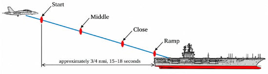
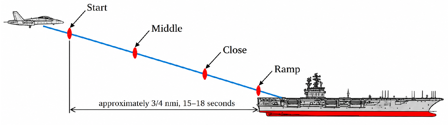
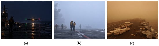
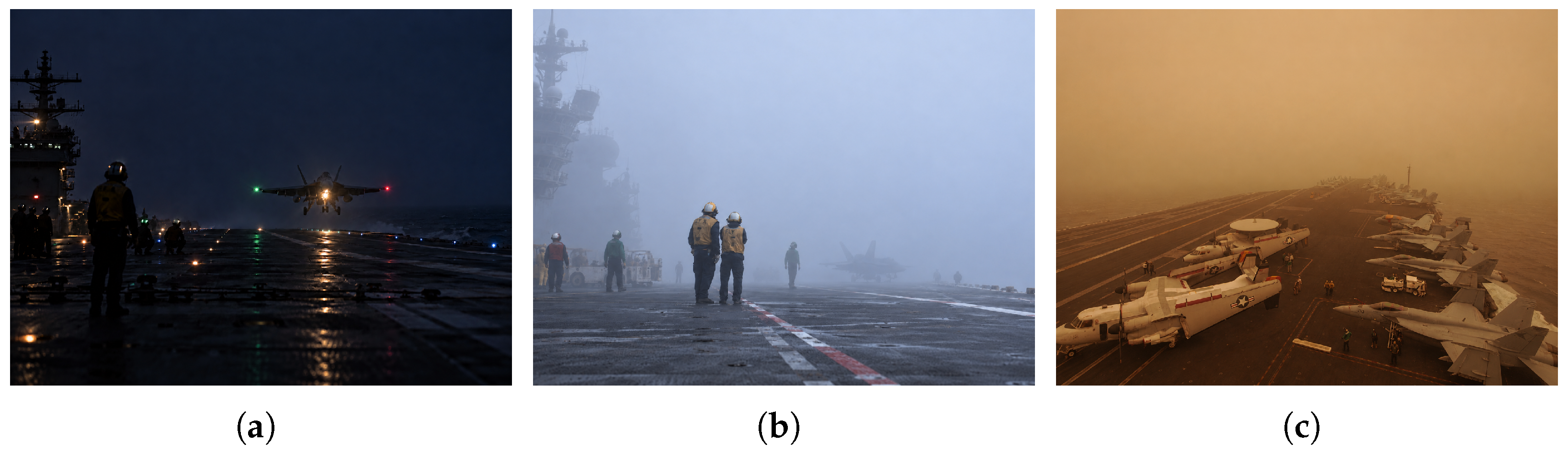
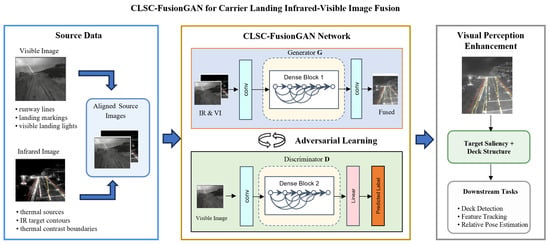
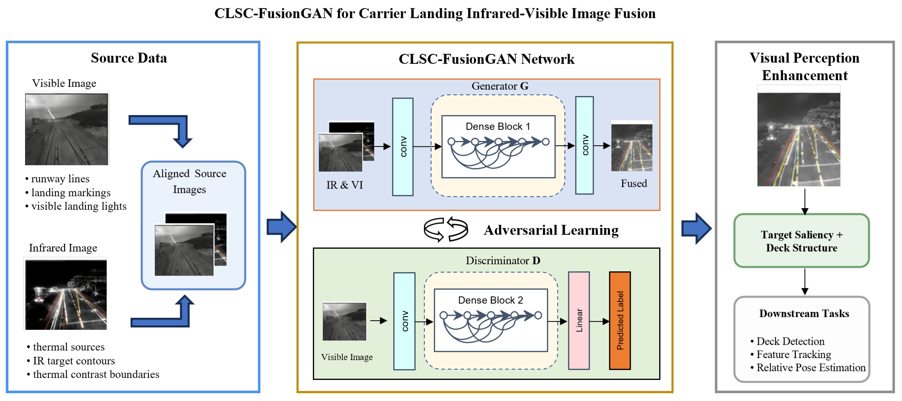
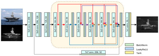
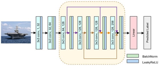
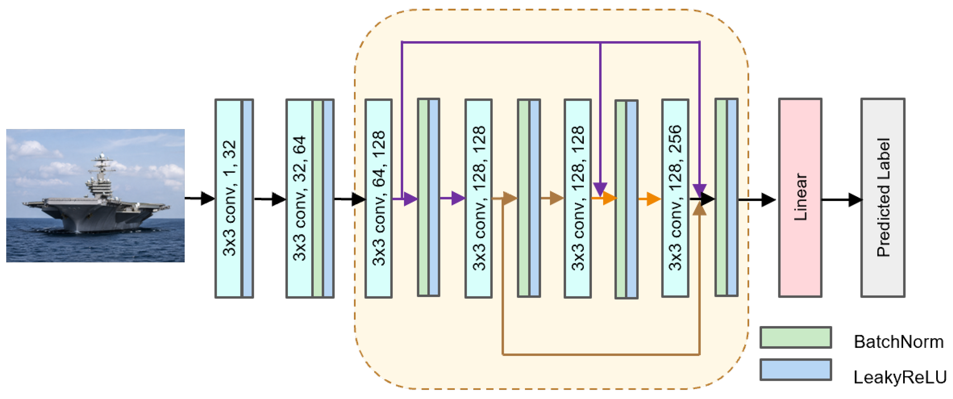
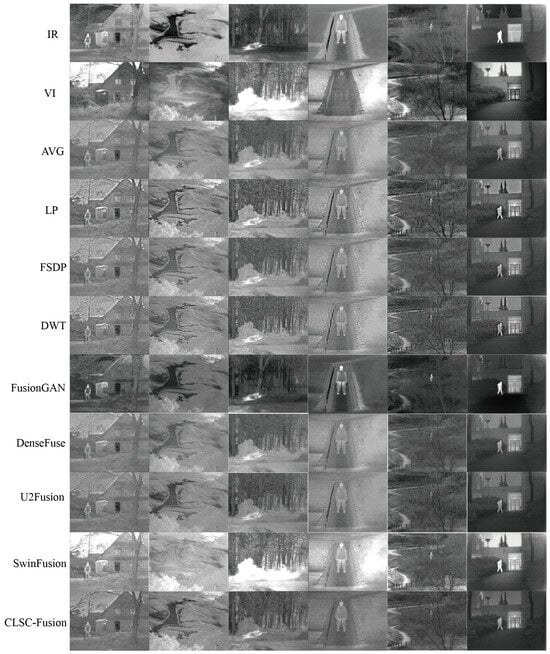
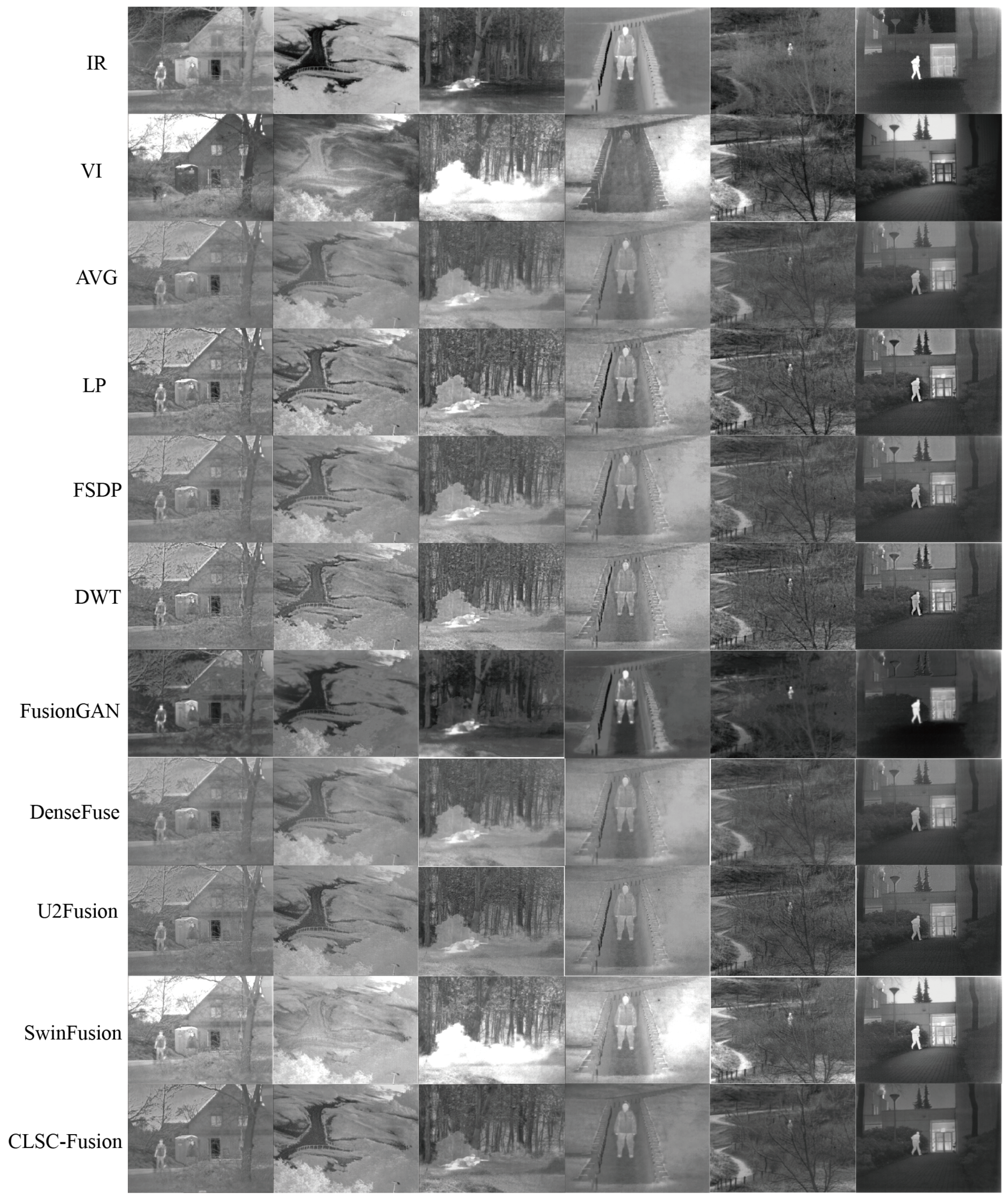
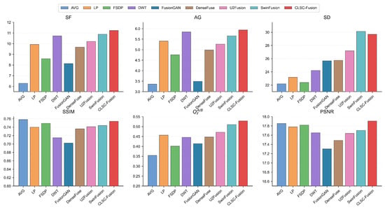
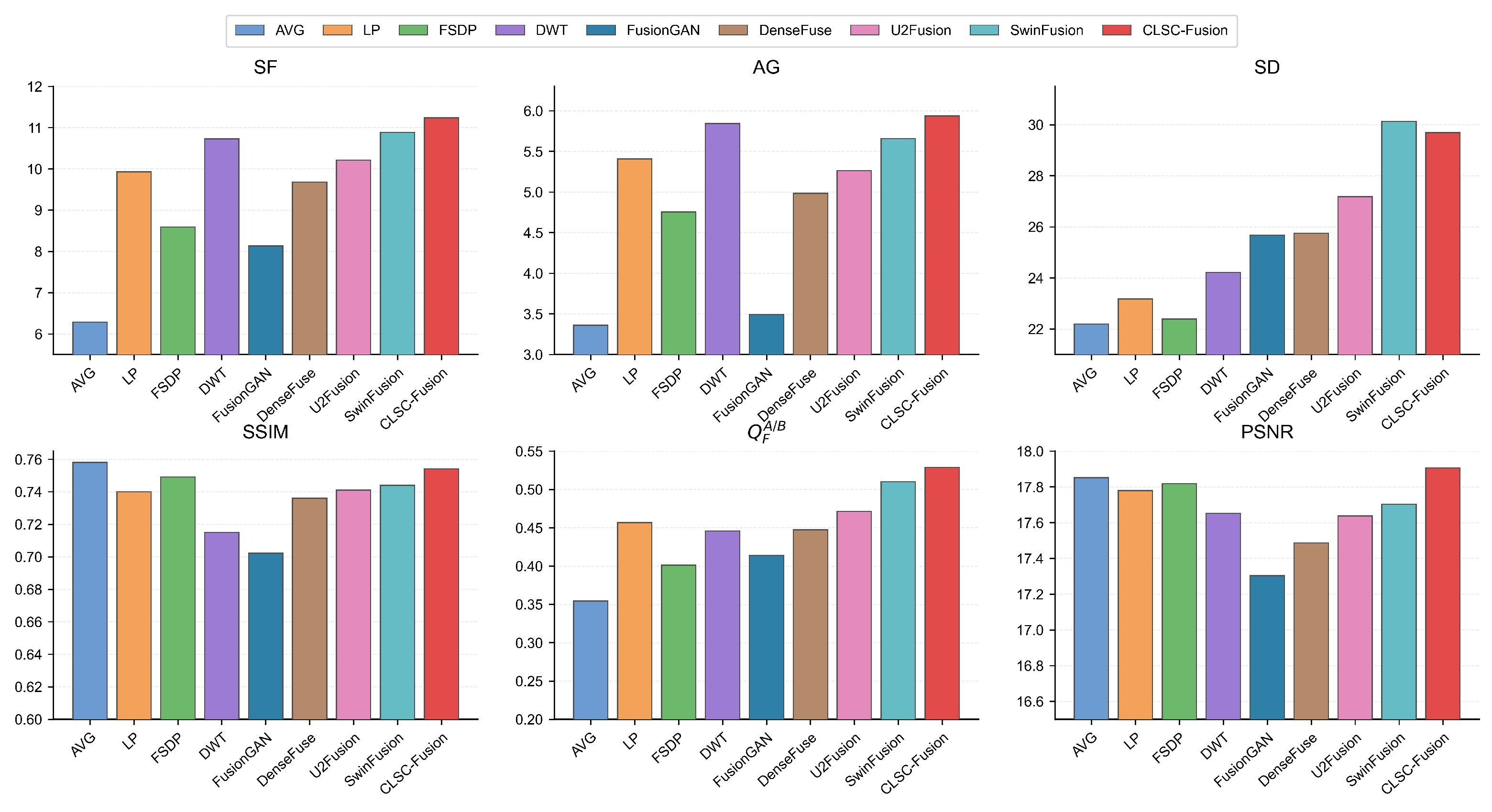
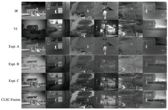
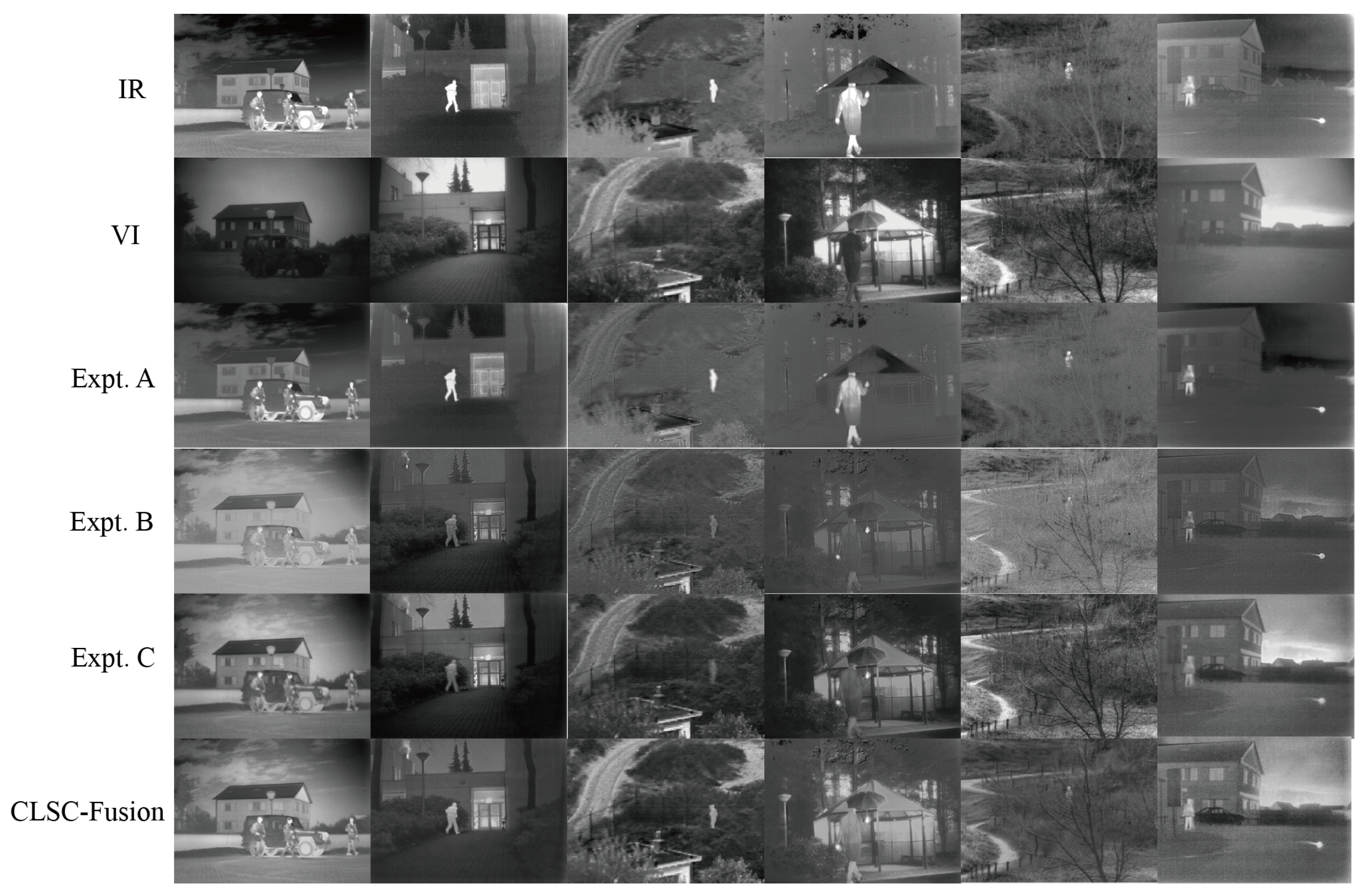
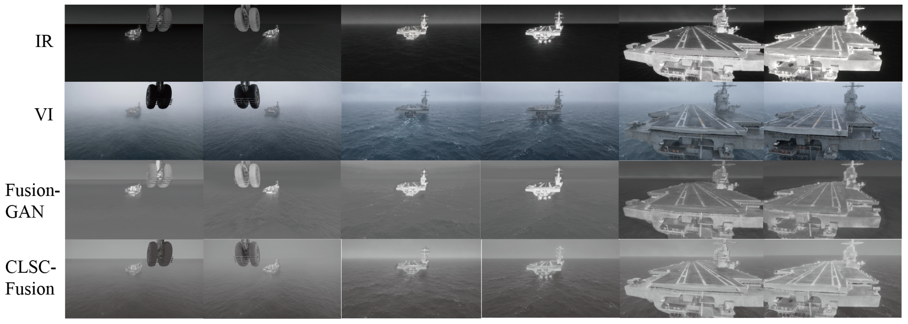

Disclaimer/Publisher’s Note: The statements, opinions and data contained in all publications are solely those of the individual author(s) and contributor(s) and not of MDPI and/or the editor(s). MDPI and/or the editor(s) disclaim responsibility for any injury to people or property resulting from any ideas, methods, instructions or products referred to in the content. |
© 2026 by the authors. Licensee MDPI, Basel, Switzerland. This article is an open access article distributed under the terms and conditions of the Creative Commons Attribution (CC BY) license.