


Abstract
This paper introduces a mathematical method for predicting the electromagnetic performance of an axial flux magnetic gear. The analytical approach, referred to as harmonic modeling, uses a complex Fourier series and the Cauchy product to obtain solutions to the partial differential equations governing the flux-density distribution and torque values in the machines. Unlike the conventional magnetic equivalent circuit method, which provides only average quantities, the proposed approach enables the prediction of spatial flux-density distributions. A 4/15/11 model was evaluated by comparison with three-dimensional finite element method simulations. The results of the flux density and torque demonstrate that the proposed method agreed well with the FEM. An extended analysis of harmonic selection was proposed, which improves the torque prediction with errors of about 3%.
MSC:
35-04
1. Introduction
Unlike conventional mechanical gears, magnetic gears (MGs) transmit torque between high-torque, low-speed and low-torque, high-speed shafts through magnetic-field interactions rather than mechanical contact between gear teeth. This contactless operation provides several advantages, including inherent overload protection, reduced maintenance, improved reliability, and physical isolation between the shafts, making MGs promising candidates for gearless and direct-drive applications. The concepts of coaxial and axial magnetic gears were introduced in [1,2], respectively. To improve output power, a concept using high-temperature superconducting (HTS) bulk was applied to the coaxial MG in [3]. Axial flux MGs (AFMGs) are a class of magnetic couplings that can tolerate relatively large radial and angular misalignments while maintaining effective torque transmission. Accurate prediction of the air-gap magnetic-field distribution is therefore essential for the design and optimization of AFMGs.
The finite element method (FEM) has been extensively employed for evaluating the electromagnetic characteristics of MGs, particularly for investigating air-gap flux-density distributions and torque or force generation [4,5,6]. For AFMGs, relatively few studies have systematically compared single-sided and double-sided configurations. In [7], a parametric investigation was therefore carried out to assess the effects of the AFMG topology on volumetric torque density and magnet utilization. An alternative design strategy was presented in [8], where the conventional arrangement of alternating north–south permanent magnets was replaced by a consequent-pole configuration. In this topology, only one magnetization direction is required, while the complementary pole is formed by the flux-modulation structure, thereby reducing the amount of permanent-magnet material while maintaining torque production. Beyond standalone MG applications, MGs can also be integrated with an electrical machine to form a magnetically geared machine, offering the potential for increased torque and power density within a compact structure. For example, an AFMG integrated with a radial-flux permanent-magnet synchronous motor (PMSM) was investigated in [9]. Considerable torque-density levels have also been demonstrated in other compact magnetic-gear designs, with reported values of 15 Nm/L for an outer radius of 50 mm, 100 Nm/L for an outer radius of 62.5 mm, and 60.6 Nm/L for an outer radius of 130 mm in [10,11,12], respectively.
In contrast to the FEM, analytical methods such as magnetic equivalent circuit (MEC), subdomain modeling (SM), and harmonic modeling (HM) offer shorter computational times, making them suitable for the pre-design stage and sizing optimization processes.
Compared with field-based analytical approaches, the MEC method represents the electromagnetic system as a reluctance network, in which permanent-magnet sources and magnetic reluctances are converted into circuit elements and interconnected according to the dominant flux paths [13,14,15,16,17]. This formulation provides a computationally efficient framework for evaluating different MG configurations and is particularly attractive for design optimization because the circuit parameters can be readily modified according to the machine geometry. For instance, an MEC model was proposed to derive the flux-density distribution in [13]. An MEC-based model combined with a multi-objective genetic algorithm (MOGA) was developed in [14] to optimize the design and electromagnetic performance of an AFMG. The flexibility of the reluctance-network representation was further demonstrated in [15], where a two-dimensional (2-D) MEC was employed to investigate a coaxial MG equipped with a Halbach permanent-magnet array. Extensions toward three-dimensional (3-D) modeling have also been reported. A 3-D MEC formulation incorporating the axial flux-linkage effect was presented in [16], while [17] investigated the numerical treatment of nonlinear magnetic materials by comparing the fixed-point and Newton–Raphson iterative methods for a 3-D MEC model.
Beyond equivalent-circuit formulations, field-based analytical methods have been developed by directly solving the governing partial differential equations (PDEs) of the electromagnetic problem. Among these approaches, SM and HM have been widely adopted for electrical-machine analysis. In the SM, the magnetic field is obtained by solving the governing PDEs within predefined material regions, with the field variables commonly expanded into Fourier series. This approach has been applied to both coaxial and axial MGs [18,19]. In particular, ref. [19] investigated an axial MG using a 2-D cylindrical approximation of the original 3-D geometry. For the considered case, this dimensional reduction resulted in an approximately 30% overestimation of the maximum torque compared with the corresponding 3-D analysis. The SM framework was further combined with a design optimization procedure in [20], where the torque density and permanent-magnet utilization of the MG were optimized, achieving a reported torque density of 108 Nm/L.
Despite its relatively straightforward field formulation, the conventional SM generally assumes an infinitely permeable ferromagnetic core, which limits its applicability when finite core permeability and magnetic saturation need to be considered. Moreover, as machine geometry becomes more complicated, particularly for machines containing a large number of stator slots or multiple interacting regions, the number of subdomains and associated boundary conditions can increase substantially, leading to bulky formulation and higher computational cost. To overcome these limitations, the HM has been developed as an alternative PDE-based analytical framework. By expressing the relevant electromagnetic quantities using complex Fourier series and employing the Cauchy product to describe their spatial interactions, the HM can incorporate finite and spatially varying core permeability into the field solution. This approach has been applied to PMSMs, where electromagnetic performance analysis and optimization were investigated in [21], while rotor eddy-current losses were evaluated in [22]. These formulations were established in the cylindrical coordinate system . In [23], the HM approach was further extended to a yokeless and segmented armature (YASA) axial-flux permanent-magnet motor using the corresponding coordinate system .
The limitations associated with conventional 2-D formulations have motivated the development of analytical approaches that retain the 3-D characteristics of electrical machines, particularly the effects arising at the end regions. One of the early efforts employed Fourier-based formulations to obtain analytical solutions for 3-D electromagnetic fields in structures containing ferromagnetic materials [24]. Subsequently, ref. [25] developed a 3-D analytical model for an axial-field permanent-magnet coupling by transforming the original cylindrical geometry into a Cartesian coordinate system. The magnetic scalar potential was adopted to describe the rotor-core and magnet regions, and the resulting field distributions were expanded using a 2-D Fourier series to evaluate the torque. Following these developments, 3-D analytical formulations have been extended to a variety of electromagnetic devices and machine topologies. Applications include axial MGs [25,26], eddy-current brakes [27,28], reluctance couplings [29], superconducting axial-flux machines [30,31], and ironless-stator axial-flux machines [32].
This work extends the application of the HM to AFMGs by developing a 3-D analytical formulation based on the governing PDEs. Section 2 presents the proposed 3-D HM formulation and its application to the considered AFMG topology. Section 3 validates the proposed method through comparisons between the 3-D HM and FEM results. Finally, Section 4 investigates the effects of the selected hyperparameters on the modeling accuracy and computational time.
2. Harmonic Modeling Framework
2.1. Assumptions
Initially, the following assumptions were made:
- The model is formulated in a 3-D Cartesian coordinate system;
- The scalar potential , magnetization vector , magnetic field strength , and magnetic flux-density vector have the following non-zero components: ; ; and ;
- Local areas have uniform permeability and the magnet’s relative permeability is 1.
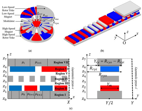
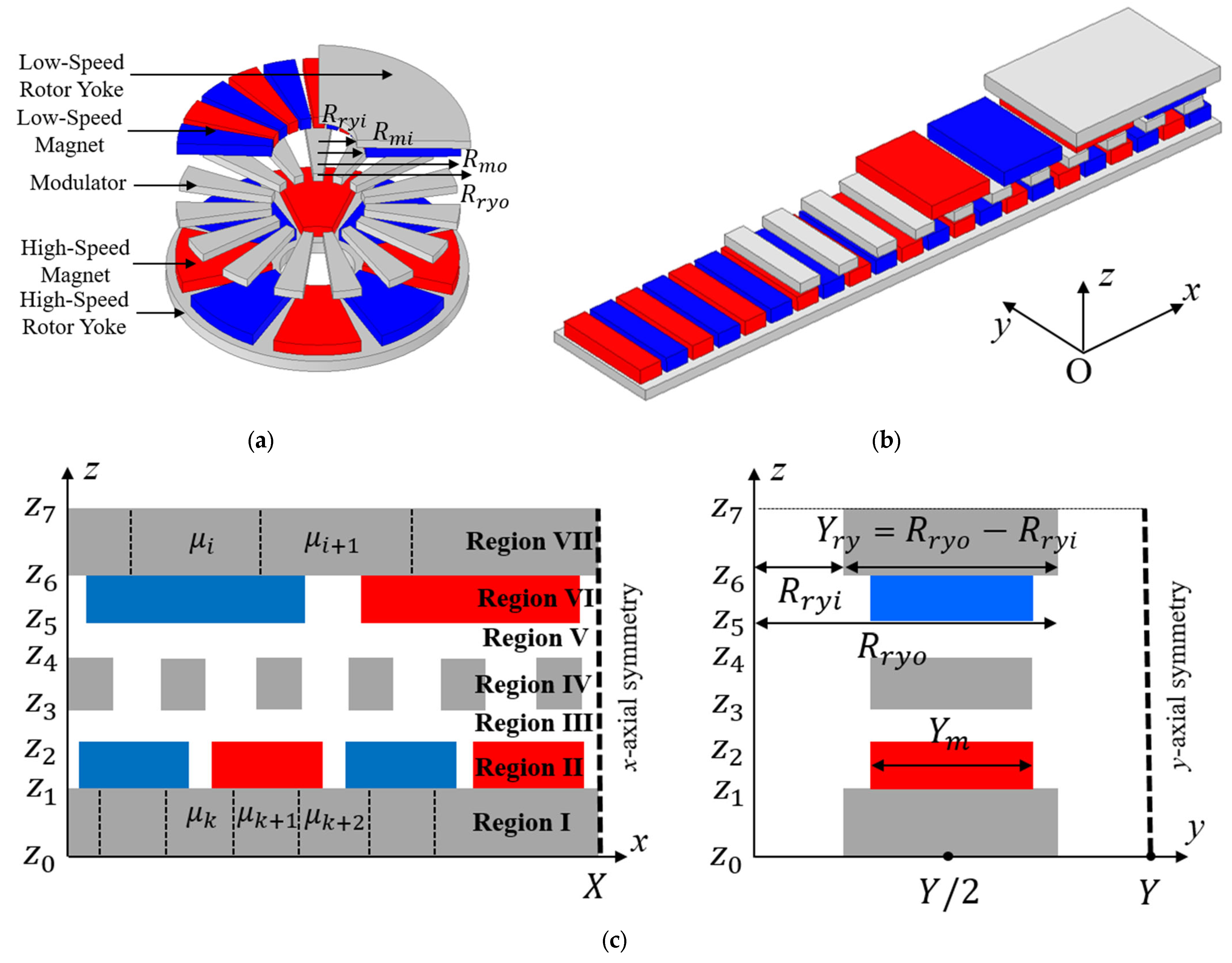
The conversion from the actual AFMG to the linearized MG is shown in Figure 1a,b. In this conversion, the magnet pole pitch and modulation pole ratio are maintained. The x-axis length of the linearized MG is determined from the circumference at the average magnet radius of the actual AFMG. The y-axis lengths of the components of the linearized MG are defined based on the corresponding inner and outer radii.
Figure 1.
(a) Actual, (b) axial-linearized, and (c) simplified analytical models.
The simplified analytical model of the AFMG is depicted in Figure 1c. In the plane, the model is divided into seven regions as follows: two air gaps, two magnet layers, two rotor yokes, and one modulation layer. Unlike the SM approach, in which the rotor yoke is often considered as a single region with an infinite-permeability assumption, the proposed HM separates the rotor yoke into a number of subregions whose permeability values are defined. Based on the number of rotor magnets, the number of subregions is defined as follows. Since the flux tends to flow through the subregions between two adjacent magnets, the flux density in these areas can reach higher values, resulting in saturation. Consequently, their permeability values decrease. A periodic boundary condition is applied at the x-direction boundaries, , because of the symmetry of the magnetic field.
Regarding the plane, the solving length in the y-direction is intentionally selected to be roughly two or three times the magnet length in the y-direction. This is because the magnetic field decreases to zero at the y-direction boundaries. Therefore, the zero-boundary condition can be assumed.
The corresponding parameters are listed in Table 1.
Table 1.
Parameters of axial-linearized models.
2.2. Distribution of Magnet Magnetization and Permeability
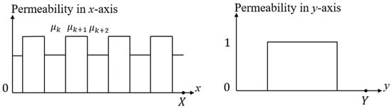
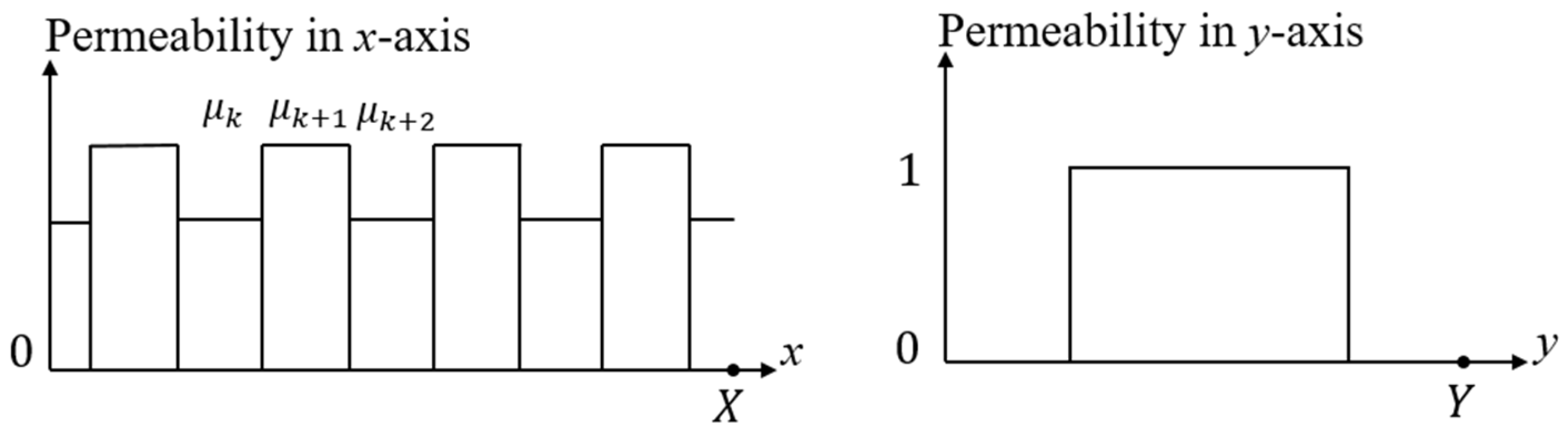
In a given region represented by the x- and y-direction components, the x-direction component describes the spatial variation in the quantity, whereas the y-direction component indicates where the quantity is present or absent, as illustrated in Figure 2.
Figure 2.
Illustration of 2-D Fourier series expansions.
The quantity can be expressed as a 2-D complex Fourier series expansion:
where is initial position in the x-direction.
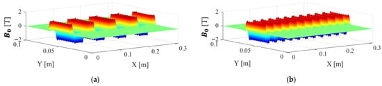
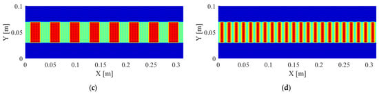
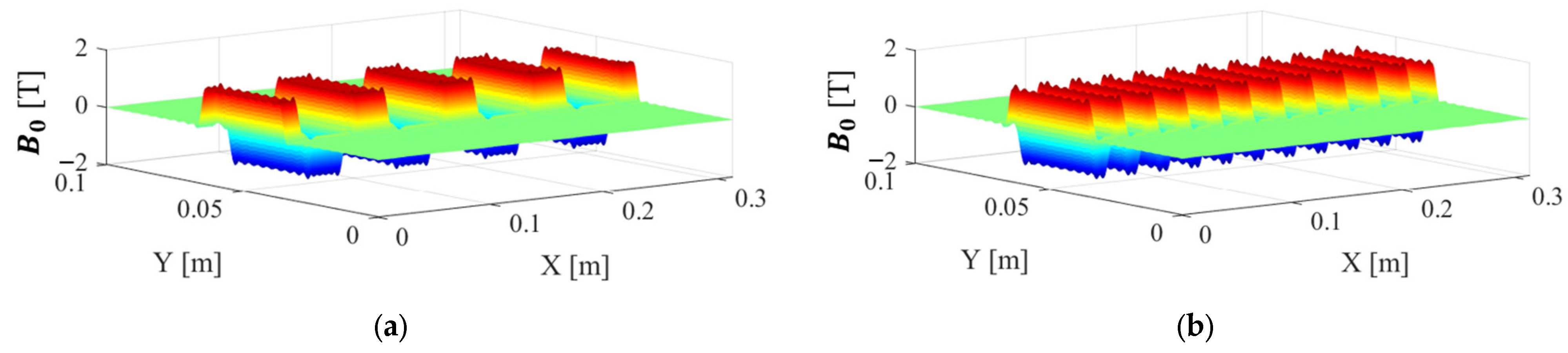
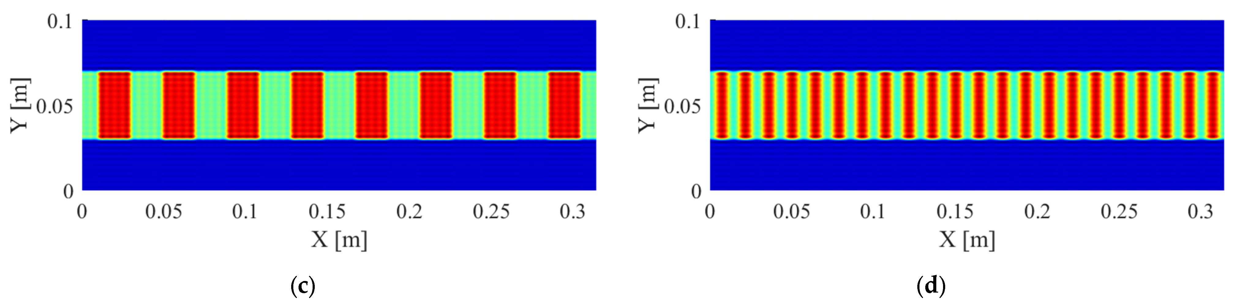
Figure 3 shows the programmed distributions of the magnet magnetization and permeability.
Figure 3.
(a,b) Magnet magnetization and (c,d) permeability results calculated by (1).
The HM framework is implemented based on matrix quantities. Therefore, Equation (1) is rewritten in matrix form.
where is a element column matrix containing the Fourier coefficients ; and are diagonal matrices.
With functions and being the remainder of the division of and and the rounding toward zero of , respectively, the index of matrices is defined as:
Since the relation between and is given by , and - quantities are represented by the column matrices , the relative permeability must be represented by a square matrix. This matrix can be referred to as the convolution matrix. The relative permeability is represented as a convolution matrix as follows:
In the 3-D HM analysis, the magnetic field strength and magnetic flux-density vectors have three components, given by and , respectively. Therefore, three convolution matrices are required to represent the relationship between and . To ensure good convergence of the perpendicular components, the three convolution matrices of the relative permeability are given by:
2.3. Governing Partial Differential Equations (PDEs)
Letting , the scalar potential is calculated by solving the following PDE [29]:
The PDE general solution for the kth region (regions I to VII are with respect to the radius to ) depicted in Figure 1c can be formulated as follows:
where the vectors and are the column vectors of the constant’s unknown coefficient.
The presence of relative permeability in makes it not diagonal, which is computationally expensive when solving later. Eigen-decomposition is applied to . With and denoting the diagonal eigenvalue matrix and the eigenvector matrix of , the scalar potential in region I is given by:
Notably, magnetization is non-zero in regions II and VI, and the core permeability is considered in regions I, IV, and VII. The magnetic field strength and magnetic flux density are calculated as follows:
2.4. Boundary Conditions
In total, there are 14 coefficients in (7). Thus, determining a unique solution requires us to derive 14 corresponding equations. The continuity of the vector potential components results in the following boundary conditions:
By collecting the boundary conditions from (10), the following total matrix equation is obtained:
With the harmonic orders N and K, the total number of unknown coefficients in (11) is . The coefficients were determined in Appendix A.
2.5. Electromagnetic Torque
The x-axis force and electromagnetic torque are determined from the Maxwell stress tensor in the middle air-gap plane.
where is the conjugate vector of the .
3. FEM Simulation Comparison
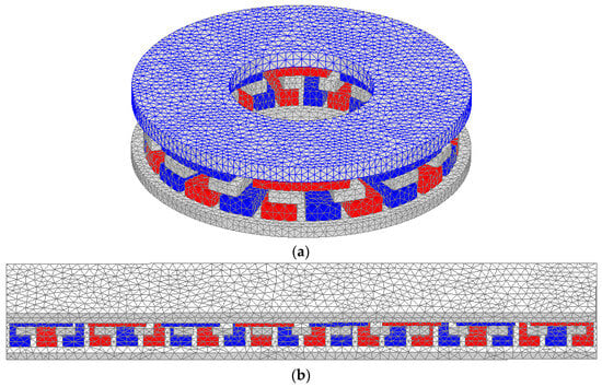
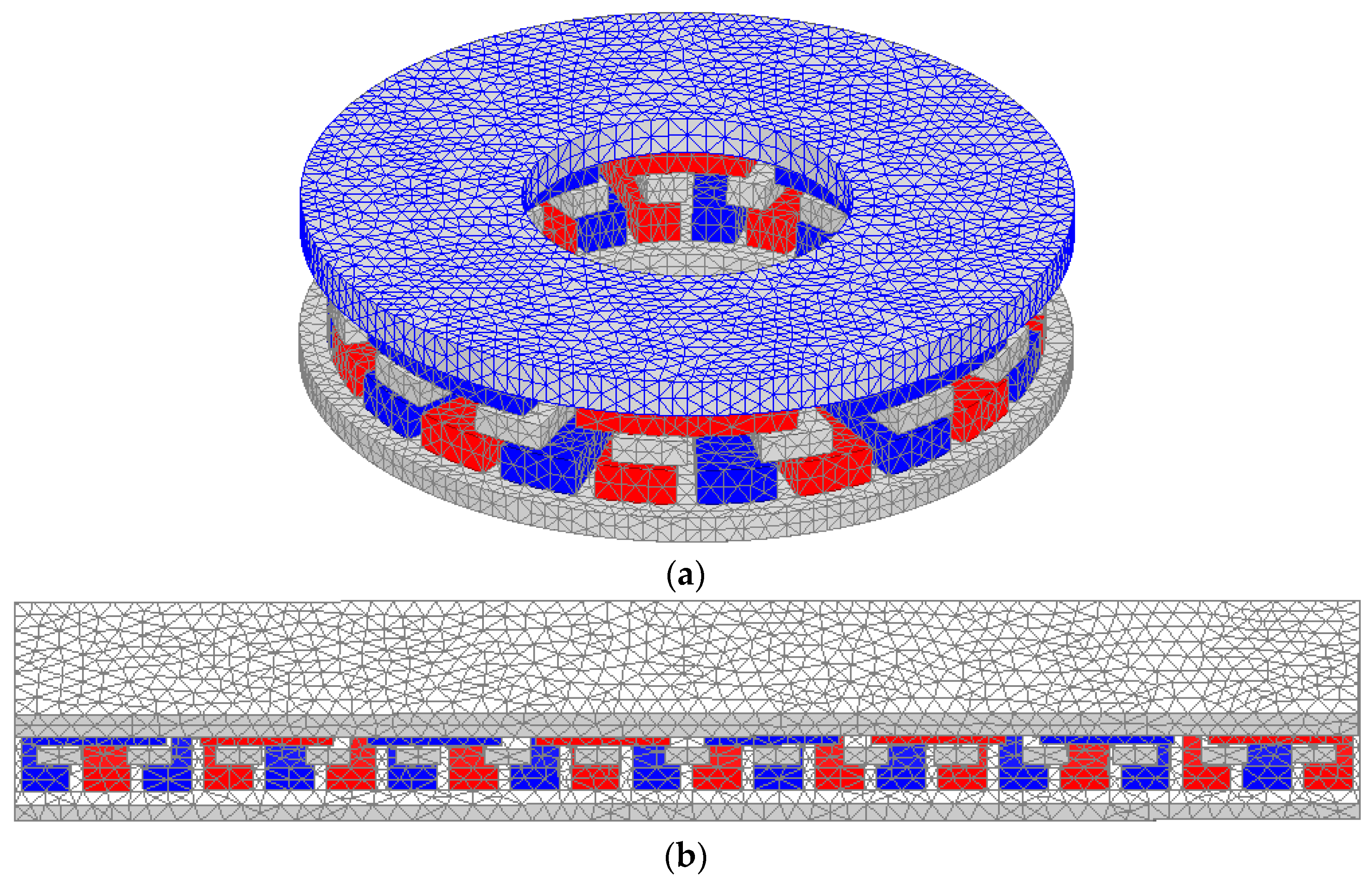
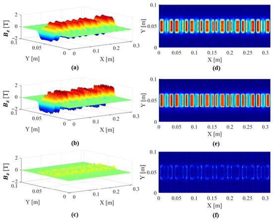
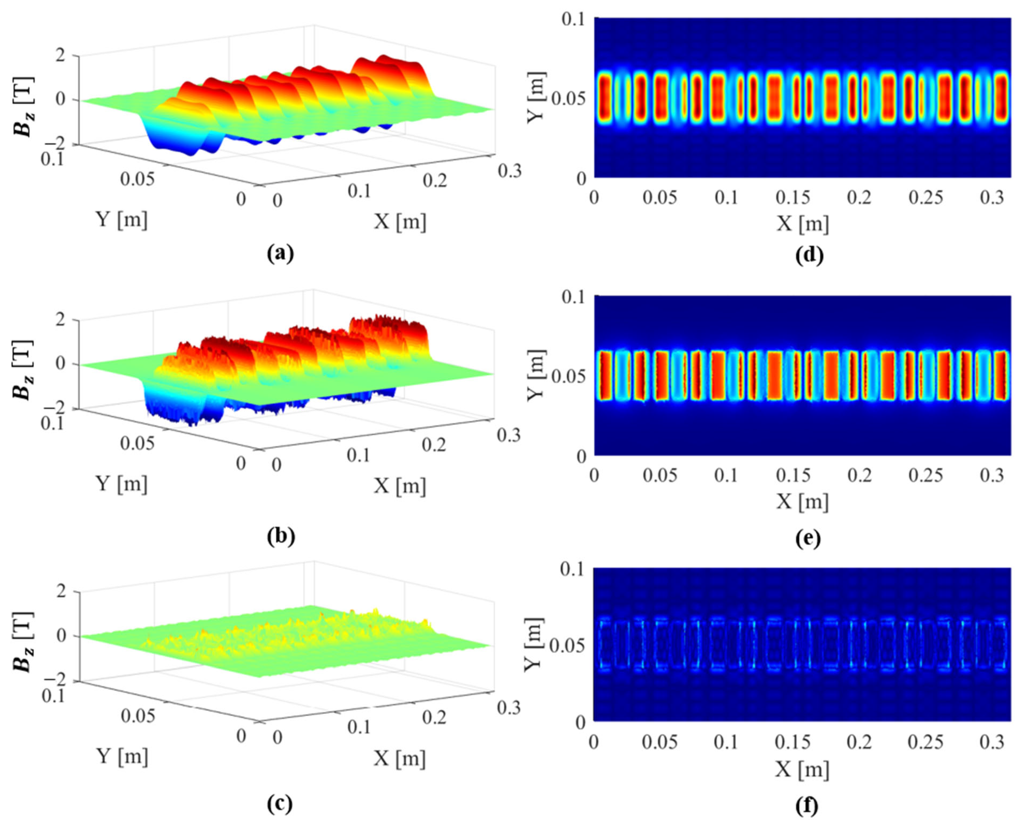
The relative permeability of the rotor yokes and modulation layer is set to in region I, in region VII, and in region IV. The harmonic numbers of the 3-D HM are selected as and , while the mesh size for both the actual AFMG and the linearized-converted MG is set to approximately 200,000 elements, as depicted in Figure 4. Since the proposed HM is formulated in the Cartesian coordinate system, the resulting flux-density distributions are not directly compatible with the geometry of the actual AFMG. Therefore, the linearized MG is also presented for better visualization while preserving the accuracy of the results for the actual AFMG. In this section, the flux-density distributions are first investigated in the two air gaps (regions III and V). Subsequently, the static torques of the inner and outer rotors are compared among the actual AFMG, the linearized MG, and the simplified analytical model.
Figure 4.
Mesh operation of (a) AFMG and (b) linearized equivalent MG.
To ensure a consistent performance benchmark, we performed both the HM and FEM simulations on the same computing platform, featuring a 12th Gen Intel Core i9-12900KF processor operating at 3.19 GHz.
Flux-density distributions between the HM and FEM are compared in Figure 5 and Figure 6. In general, the HM results agree well with the FEM predictions. Since region II corresponds to the high-speed rotor, which contains eight magnets, eight distinct flux-density regions can be observed in the plane, as shown in Figure 5. The flux density of each magnet pole is periodically reduced by air regions within the modulation layer. This phenomenon results from the modulation effect of the ferromagnetic and air regions and is analogous to the slotting effect commonly observed in conventional electrical machines.
Figure 5.
HM, FEM, error between HM and FEM results of (a–c) z-direction flux density and (d–f) total flux density in region III.
Figure 6.
HM, FEM, error between HM and FEM results of (a–c) z-direction flux density and (d–f) total flux density in region V.
Similar to region II, region VI contains twenty-two magnets. Therefore, twenty-two distinct flux-density regions can be observed in the plane, as shown in Figure 6. The slotting effect also appears in the air-gap flux-density distribution, and the HM results agree well with the FEM predictions. Notably, because the HM is developed based on a Fourier harmonic series, its resulting flux-density waveform is smoother than that obtained from the FEM. The FEM model is discretized into approximately 200,000 mesh elements, resulting in a slightly rougher flux-density distribution surface.
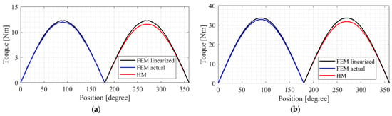
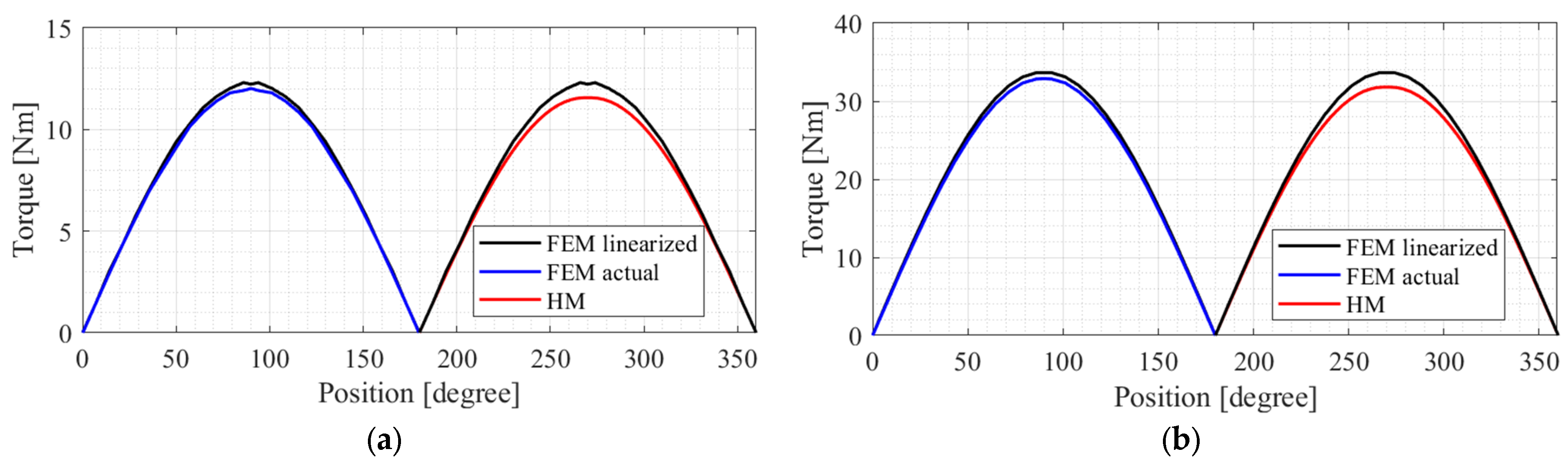
The high-speed rotor static torque is shown in Figure 7. The static torque is obtained by keeping the modulation layer and low-speed rotor stationary while only the high-speed rotor rotates. First, the results obtained from the actual AFMG and the linearized model show close agreement, with an error of approximately 2% at the peak torque. This indicates that the conversion from the axial to the linearized model is sufficiently accurate. The predicted torque of the HM also agrees well with that of the linearized model, with an error of approximately 5.5% at peak torque. Specifically, the maximum torques obtained from the linearized FEM and HM are 12.24 Nm and 11.57 Nm, respectively.
Figure 7.
Rotor torque comparison of (a) high-speed and (b) low-speed sides.
To obtain the static torque of the low-speed rotor, the modulation layer and high-speed rotor are kept stationary while only the low-speed rotor rotates. The maximum torques obtained from the linearized FEM, actual FEM, and HM are 33.65 Nm, 32.88 Nm, and 31.80 Nm, respectively. Notably, the torque ratio is approximately 2.75, which agrees well with the magnet ratio of 11/4. This result confirms the magnetic gear principle, in which torque is transferred from the low-speed rotor to the high-speed rotor.
Notably, the static torque shown in Figure 7 represents the absolute values of the torques of the low-speed and high-speed rotors. In fact, these two torques have opposite signs, indicating that the two rotors rotate in opposite directions during operation.
4. Analysis of Calculation Time
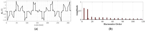
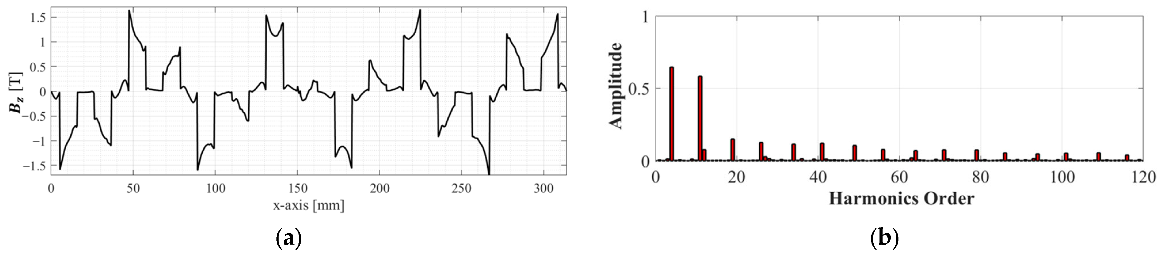
The accuracy of the proposed 3-D HM depends on the selection of the harmonic orders and . Here, represents the number of harmonics used to describe the spatial variation in quantities in the x-direction, such as the magnetization and permeability distribution. Figure 8 shows the flux-density distribution along the x-direction at and , together with its fast Fourier transform (FFT). It can be observed that dominant harmonic orders, i.e., 4, 11, 19, 26, 34, 41, …, are related to the pole-pair numbers of the two rotors, and . These harmonic orders can be expressed as:
Figure 8.
(a) Flux density in region IV and (b) its FFT analysis.
Therefore, the selected harmonic order N should be sufficiently large to include the dominant harmonics in the flux-density distribution, thereby ensuring good accuracy.
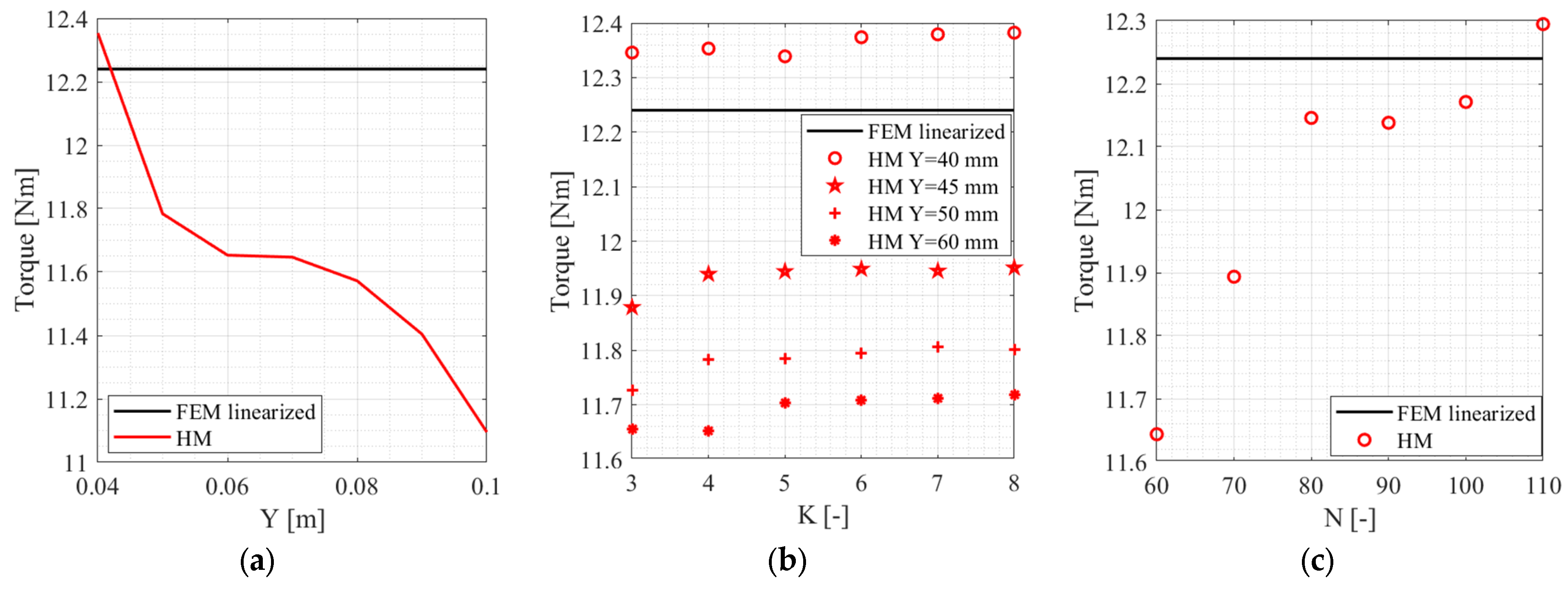
For , which represents the spatial variation in the y-direction as illustrated in Figure 2, its required value depends on the selected y-axis length . As mentioned previously, the y-axis length should be sufficiently larger than the active magnet length to satisfy the boundary conditions . Increasing generally requires more harmonics , which increases the computational burden. Conversely, when a shorter is selected, the required number of harmonics can be reduced. However, the magnetic flux density at the y-direction boundaries may no longer approach zero because of the machine end effect, which results in a violation of the assumed boundary conditions. Therefore, an appropriate combination of and is required to achieve a balance between computational efficiency and modeling accuracy.
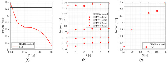
Figure 9 shows the high-speed rotor torque under different conditions. Figure 9a illustrates the predicted torque as a function of the y-direction length , with and . As increases, the selected harmonic order becomes insufficient for accurately describing the spatial variation in the active regions. Consequently, the predicted torque gradually decreases as increases. This issue can be addressed by increasing ; however, a higher harmonic order also increases the computational burden.
Figure 9.
Maximum torque of high-speed rotor at (a) N = 64, K = 4; (b) N = 64; and (c) K = 4, Y = 50 mm.
Figure 9b shows the predicted torque as a function of K for different values of . In general, accuracy improves as the harmonic order increases. At mm, however, the predicted torque is higher than the FEM result. This can be attributed to insufficient representation of the end effect because the y-direction length of the rotor yoke, , is 40 mm, which is equal to mm. Notably, the computational time increases rapidly (7.0 s, 10.1 s, 16.7 s, 26.3 s, 40.5 s, and 57.8 s) as K increases from 3 to 8.
Similar to , increasing the harmonic order improves modeling accuracy, as shown in Figure 9c. However, the computational time also increases significantly (8.4 s, 12.1 s, 17.2 s, 23.0 s, 31.9 s, and 43.2 s) as increases from 60 to 110. Based on these results, , , and mm are selected as suitable parameters for predicting both the flux-density distribution and torque using the proposed HM.
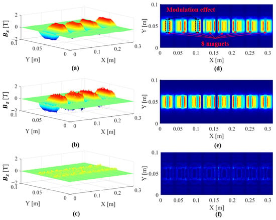
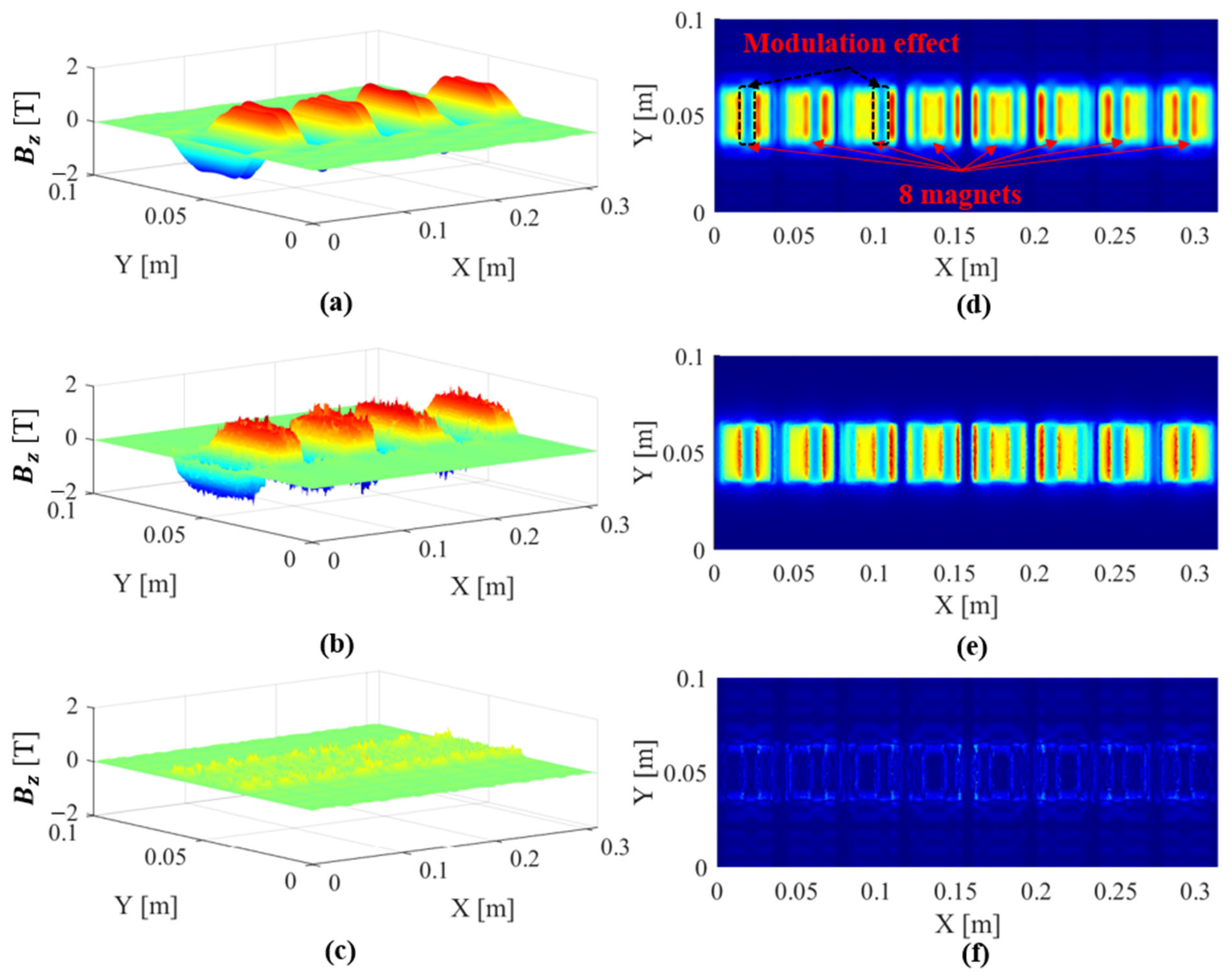
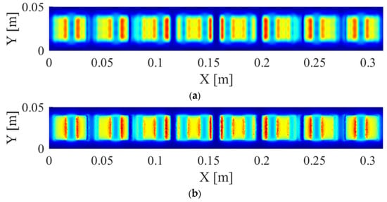
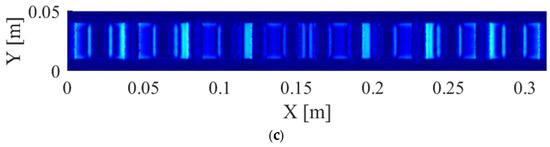
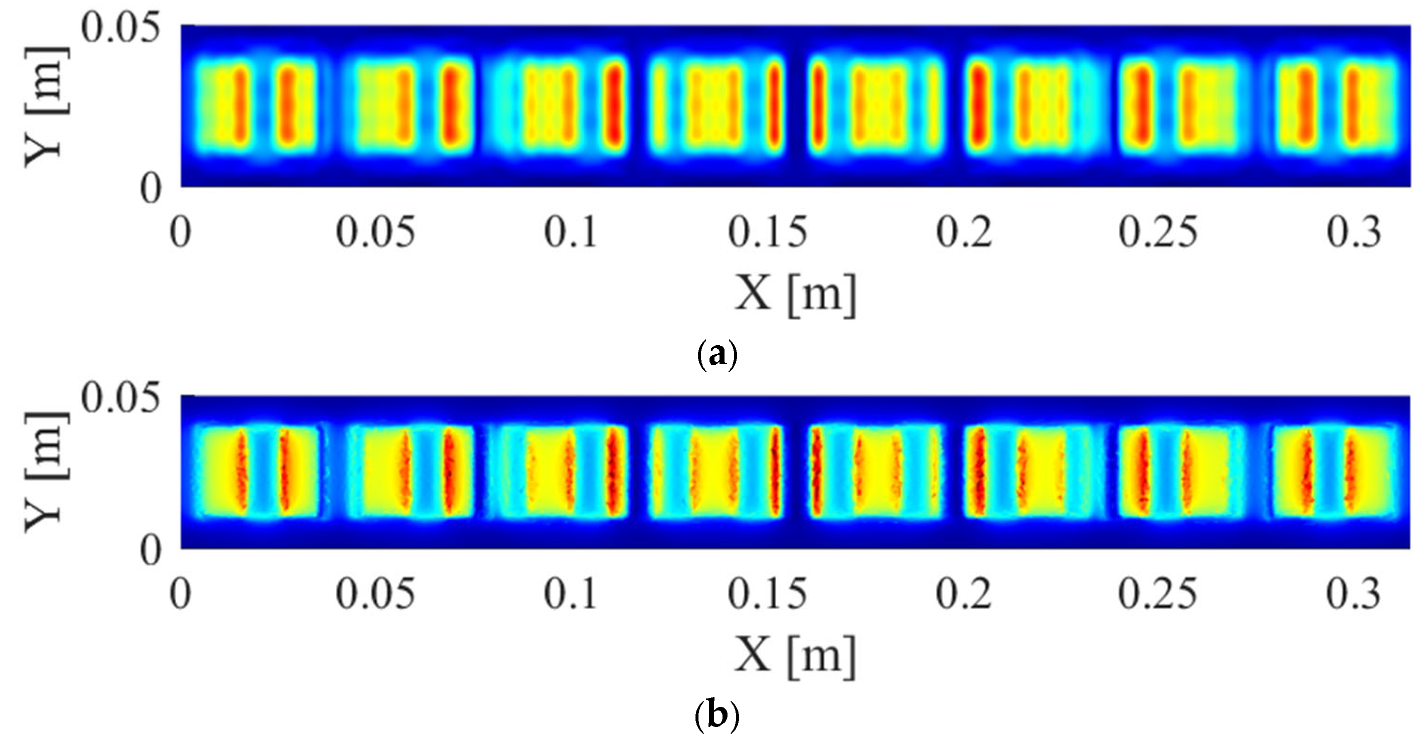
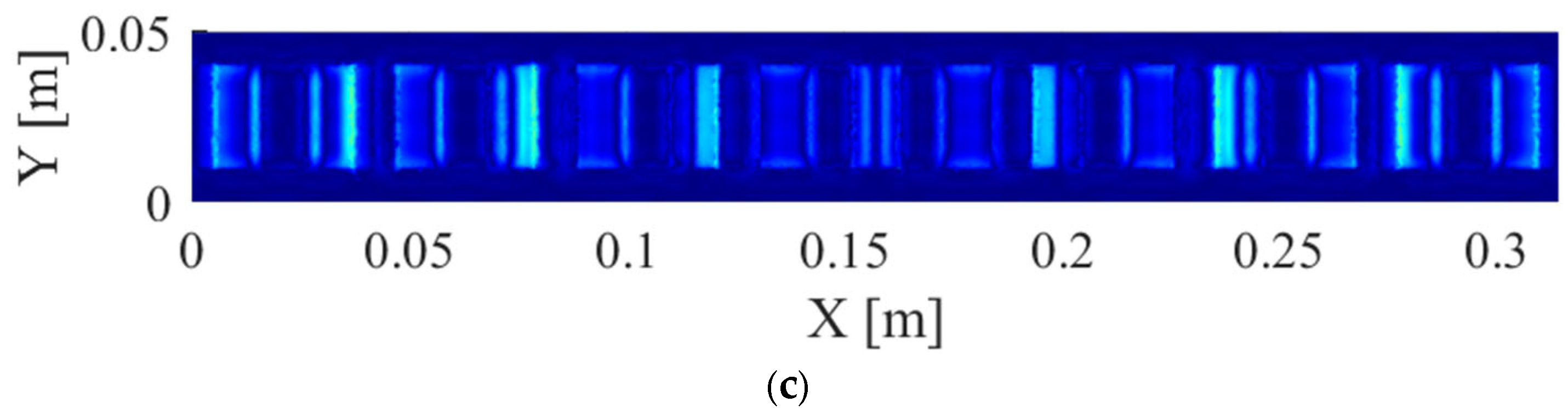
Figure 10 compares flux-density distributions obtained from the HM and FEM under the selected conditions of , , and mm. The results show that the proposed HM captures both the end effect and slotting effect well. Moreover, the torque error is approximately 3% compared with the FEM result, while the computational time is only 12 s. At the maximum torque point, this computational time is significantly shorter than that of the FEM, which requires approximately 90 s for a 200,000-element mesh.
Figure 10.
Flux density comparison in region III among (a) HM, (b) FEM, and (c) error.
5. Conclusions
The proposed mathematical method is an efficient approach for determining the flux density and torque of an AFMG. In this paper, a 3-D analytical approach is presented to solve PDEs. The boundary conditions within the machine are derived for both the x- and y-directions. The proposed model was validated through 3-D FEM simulations under various operating conditions; the results demonstrate high accuracy while achieving a computational time saving of more than 7.5 times compared to 3-D FEM simulations.
Based on the methodology and findings of this study, the following future research avenues are suggested:
- ➢
- Consider the nonlinear characteristics of core parts;
- ➢
- Develop an HM-based optimization for sizing machine process;
- ➢
- Verify the HM prediction experimentally using a prototype.
Author Contributions
Conceptualization, M.-D.N.; methodology, M.-D.N.; validation, M.-D.N.; writing—original draft preparation, M.-D.N.; writing—review and editing, D.-T.H., K.-H.S. and J.-Y.C.; supervision, K.-H.S. and J.-Y.C. All authors have read and agreed to the published version of the manuscript.
Funding
This work was supported by Korea Institute of Planning and Evaluation for Technology in Food, Agriculture and Forestry (IPET) through the Agriculture and Food Convergence Technologies Program for Research Manpower development, funded by Ministry of Agriculture, Food and Rural Affairs (MAFRA) (project no. RS-2024-00397026).
Data Availability Statement
The original contributions presented in this study are included in the article. Further inquiries can be directed to the corresponding authors.
Conflicts of Interest
The authors declare no conflicts of interest.
Appendix A
By combining (7), (8), and (9), the boundary condition in (10) turns out:
By combining (7), (8), and (9), the boundary condition in (10) turns out:
By combining (7), (8), and (9), the boundary condition in (10) turns out:
By applying the remaining boundary conditions given in (10), the coefficients in (11) are determined.
References
- Atallah, K.; Howe, D. A novel high-performance magnetic gear. IEEE Trans. Magn. 2001, 37, 2844–2846. [Google Scholar] [CrossRef] [Scilit]
- Ahmadreza Afsari, S.; Heydari, H.; Dianati, B. Cogging Torque Mitigation in Axial Flux Magnetic Gear System Based on Skew Effects Using an Improved Quasi 3-D Analytical Method. IEEE Trans. Magn. 2015, 51, 7403111. [Google Scholar] [CrossRef] [Scilit]
- Jing, L.; Su, Z.; Wang, T.; Wang, Y.; Qu, R. Multi-Objective Optimization Analysis of Magnetic Gear with HTS Bulks and Uneven Halbach Arrays. IEEE Trans. Appl. Supercond. 2023, 33, 5202705. [Google Scholar] [CrossRef] [Scilit]
- Johnson, M.; Shapoury, A.; Boghrat, P.; Post, M.; Toliyat, H.A. Analysis and development of an axial flux magnetic gear. In Proceedings of the 2014 IEEE Energy Conversion Congress and Exposition (ECCE), Pittsburgh, PA, USA; IEEE: New York, NY, USA, 2014; pp. 5893–5900. [Google Scholar] [CrossRef] [Scilit]
- Johnson, M.; Gardner, M.C.; Toliyat, H.A. Design and analysis of an axial flux magnetically geared generator. In Proceedings of the 2015 IEEE Energy Conversion Congress and Exposition (ECCE), Montreal, QC, Canada; IEEE: New York, NY, USA, 2015; pp. 6511–6518. [Google Scholar] [CrossRef] [Scilit]
- Praslicka, B.; Knight, D.F.; Stefanelli, T.L.; Palmer, N.; White, A.; Jones, J.; Toliyat, H.A. Design and Analysis of an Axial Flux Coaxial Magnetic Gear with Balanced Axial Forces for Precision Aerospace Actuation Application. In Proceedings of the 2022 IEEE Energy Conversion Congress and Exposition (ECCE), Detroit, MI, USA; IEEE: New York, NY, USA, 2022; pp. 1–8. [Google Scholar] [CrossRef] [Scilit]
- Sheshaprasad, S.; Johnson, M.; Toliyat, H.A. Design and Analysis of Double-Sided Axial Flux Coaxial Magnetic Gears. In Proceedings of the 2024 IEEE Energy Conversion Congress and Exposition (ECCE), Phoenix, AZ, USA; IEEE: New York, NY, USA, 2024; pp. 5357–5364. [Google Scholar] [CrossRef] [Scilit]
- Yousefnejad, S.; Amiri, E. Consequent-Pole Dual-Layer Axial Flux Magnetic Gear with Halbach Array. In Proceedings of the 2023 IEEE International Electric Machines & Drives Conference (IEMDC), San Francisco, CA, USA; IEEE: New York, NY, USA, 2023; pp. 1–5. [Google Scholar] [CrossRef] [Scilit]
- Kouhshahi, M.B.; Bird, J.Z.; Acharya, V.; Li, K.; Calvin, M.; Williams, W. An axial flux-focusing magnetically geared motor. In Proceedings of the 2017 IEEE Energy Conversion Congress and Exposition (ECCE), Cincinnati, OH, USA; IEEE: New York, NY, USA, 2017; pp. 307–313. [Google Scholar] [CrossRef] [Scilit]
- Wang, R.J.; Brönn, L.; Gerber, S.; Tlali, P.M. Design and evaluation of a disc-type magnetically geared PM wind generator. In Proceedings of the 4th International Conference on Power Engineering, Energy and Electrical Drives; IEEE: New York, NY, USA, 2013; pp. 1259–1264. [Google Scholar]
- Fu, W.N.; Ho, S.L. A Quantitative Comparative Analysis of a Novel Flux-Modulated Permanent-Magnet Motor for Low-Speed Drive. IEEE Trans. Magn. 2010, 46, 127–134. [Google Scholar] [CrossRef] [Scilit]
- Tong, C.; Song, Z.; Zheng, P.; Bai, J.; Zhao, Q. Research on electromagnetic performance of an axial magnetic-field-modulated brushless double-rotor machine for hybrid electric vehicles. In Proceedings of the 2014 17th International Conference on Electrical Machines and Systems (ICEMS); IEEE: New York, NY, USA, 2014; pp. 2896–2902. [Google Scholar]
- Min, Z.; Jing, L.; Wang, T.; Qu, R. A Partitioned Stator Flux Switching PM Machine with Strongly Coupled Flux Reversal Effect. IEEE Trans. Transp. Electrif. 2026. [Google Scholar] [CrossRef] [Scilit]
- Ruiz-Ponce, G.; Arjona, M.A.; Hernandez, C.; Escarela-Perez, R. Design Optimization of an Axial Flux Magnetic Gear by Using Reluctance Network Modeling and Genetic Algorithm. Energies 2023, 16, 1852. [Google Scholar] [CrossRef] [Scilit]
- Beirami, A.; Farahani, H.F.; Rahimi, R.M.; Amini, S. Dynamic analysis of Halbach coaxial magnetic gears based on magnetic equivalent circuit modelling. IET Circuits Devices Syst. 2021, 15, 260–271. [Google Scholar] [CrossRef] [Scilit]
- Lee, S.-H.; Im, S.-Y.; Ryu, J.-Y.; Lim, M.-S. Torque Prediction of Magnetic Gear considering 3D Axial Leakage Flux by Equivalent Magnetic Circuit. In Proceedings of the 2022 IEEE Transportation Electrification Conference and Expo, Asia-Pacific (ITEC Asia-Pacific), Haining, China; IEEE: New York, NY, USA, 2022; pp. 1–6. [Google Scholar] [CrossRef] [Scilit]
- Diab, H.; Amara, Y.; Barakat, G. A 3D nonlinear magnetic equivalent circuit model for an axial field flux focusing magnetic gear: Comparison of fixed-point and Newton–Raphson methods. Math. Comput. Simul. 2024, 224, 119–137. [Google Scholar] [CrossRef] [Scilit]
- Lubin, T.; Mezani, S.; Rezzoug, A. Analytical Computation of the Magnetic Field Distribution in a Magnetic Gear. IEEE Trans. Magn. 2010, 46, 2611–2621. [Google Scholar] [CrossRef] [Scilit]
- Lubin, T.; Mezani, S.; Rezzoug, A. Development of a 2-D Analytical Model for the Electromagnetic Computation of Axial-Field Magnetic Gears. IEEE Trans. Magn. 2013, 49, 5507–5521. [Google Scholar] [CrossRef] [Scilit]
- Nguyen, M.-D.; Jung, W.-S.; Hoang, D.-T.; Kim, Y.-J.; Shin, K.-H.; Choi, J.-Y. Fast Analysis and Optimization of a Magnetic Gear Based on Subdomain Modeling. Mathematics 2024, 12, 2922. [Google Scholar] [CrossRef] [Scilit]
- Nguyen, M.-D.; Hoang, D.-T.; Shin, K.-H.; Choi, J.-Y. Analysis and Optimization for Surface-Inset Permanent Magnet Synchronous Generator Considering Nonlinear Permeability Based on Harmonic Modeling. IEEE Trans. Magn. 2026, 62, 8100310. [Google Scholar] [CrossRef] [Scilit]
- Hoang, D.-T.; Nguyen, M.-D.; Han, C.; Kim, Y.-J.; Shin, K.-H.; Choi, J.-Y. Analytical Model for Predicting Rotor Eddy Current Loss of PMSMs Considering Magnetic Saturation and Diffusion Effect. IEEE Trans. Energy Convers. 2026, 41, 2383–2396. [Google Scholar] [CrossRef] [Scilit]
- Nguyen, M.-D.; Yang, J.-W.; Hoang, D.-T.; Shin, K.-H.; Choi, J.-Y. Electromagnetic Analysis of YASA Axial Flux Motor Using Harmonic Modeling Considering Non-Linear Core Permeability. IEEE Trans. Magn. 2025, 61, 8203412. [Google Scholar] [CrossRef] [Scilit]
- Smeets, J.P.C.; Overboom, T.T.; Jansen, J.W.; Lomonova, E.A. Mode-Matching Technique Applied to Three-Dimensional Magnetic Field Modeling. IEEE Trans. Magn. 2012, 48, 3383–3386. [Google Scholar] [CrossRef] [Scilit]
- Dolisy, B.; Mezani, S.; Lubin, T.; Lévêque, J. A New Analytical Torque Formula for Axial Field Permanent Magnets Coupling. IEEE Trans. Energy Convers. 2015, 30, 892–899. [Google Scholar] [CrossRef] [Scilit]
- Liu, R.; Han, H.; Zhang, J.; Sun, G.; Lin, S. 3-D Analytical Model of Magnetic Field for Axial-Flux Permanent Magnet Couplings. IEEE Trans. Magn. 2024, 60, 8000707. [Google Scholar] [CrossRef] [Scilit]
- Messadi, M.; Hadjout, L.; Takorabet, N. 3D electromagnetic analytical model for radial-flux eddy-current couplers. COMPEL 2024, 43, 634–648. [Google Scholar] [CrossRef] [Scilit]
- Lubin, T.; Rezzoug, A. 3-D Analytical Model for Axial-Flux Eddy-Current Couplings and Brakes Under Steady-State Conditions. IEEE Trans. Magn. 2015, 51, 8203712. [Google Scholar] [CrossRef] [Scilit]
- Dorget, R.; Lubin, T. Non-Linear 3-D Semi-Analytical Model for an Axial-Flux Reluctance Magnetic Coupling. IEEE Trans. Energy Convers. 2022, 37, 2037–2047. [Google Scholar] [CrossRef] [Scilit]
- Dorget, R.; Lubin, T.; Ayat, S.; Lévêque, J. 3-D Semi-Analytical Model of a Superconducting Axial Flux Modulation Machine. IEEE Trans. Magn. 2021, 57, 9000415. [Google Scholar] [CrossRef] [Scilit]
- Mirzaei, M. 3-D Analytical Modeling of Axial-Flux Air-Core Superconducting Machines. IEEE Trans. Appl. Supercond. 2026, 36, 5204216. [Google Scholar] [CrossRef] [Scilit]
- Mami, M.; Messadi, M.; Hadjout, L.; Takorabet, N. Electromagnetic analytical model for axial-flux permanent-magnet machines with a double-sided rotor and an ironless stator. COMPEL 2026, 45, 738–754. [Google Scholar]

Disclaimer/Publisher’s Note: The statements, opinions and data contained in all publications are solely those of the individual author(s) and contributor(s) and not of MDPI and/or the editor(s). MDPI and/or the editor(s) disclaim responsibility for any injury to people or property resulting from any ideas, methods, instructions or products referred to in the content. |
© 2026 by the authors. Licensee MDPI, Basel, Switzerland. This article is an open access article distributed under the terms and conditions of the Creative Commons Attribution (CC BY) license.