


Abstract
Fatigue is widely recognized as one of the primary failure mechanisms affecting metallic structures. Consequently, reliable prediction of fatigue-induced failure is essential for the safe design and lifetime prediction of engineering structures and components. In this context, the present work provides an overview of some of the main approaches employed for fatigue modeling in metals. First, the classical total-life methods, namely the stress–life and strain–life approaches, are reviewed. Subsequently, fracture-based approaches to fatigue are presented, including formulations grounded in fracture mechanics, continuum damage mechanics, and phase-field theory. The finite element method and the extended finite element method are also discussed as representative numerical frameworks for the implementation of these formulations. The reviewed approaches are then critically compared in terms of their applicability, capabilities, limitations and calibration requirements. Finally, relevant directions for future research are identified.
Keywords:
fatigue modeling; total-life methods; fracture mechanics; continuum damage mechanics; phase-field formulations; fracture-based models; finite element method; extended finite element method MSC:
74R99
1. Introduction
Beginning in the mid-19th century, the study of fatigue in metals has become, over the years, a field of major interest for materials scientists and structural engineers, mainly because it represents one of the principal failure mechanisms in metallic engineering structures. Accordingly, early fatigue assessment was largely based on empirical approaches, notably the stress amplitude–life (S–N) curves derived from Wöhler’s pioneering studies [1,2] and the strain–life (–N) diagrams emerging from the works of Coffin [3] and Manson [4]. Commonly classified as total-life approaches, these methodologies were originally intended for fatigue life estimation and remain widely employed to predict the service life of metallic components. Since the emergence of these pioneering approaches, fatigue prediction capabilities have advanced considerably, culminating in the development of sophisticated numerical models capable of predicting not only fatigue life but also the progressive degradation of material properties associated with the fatigue damage, including crack initiation and propagation processes that ultimately lead to complete structural failure [5].
Approaches exhibiting these characteristics are commonly referred to as fracture-based fatigue models. Over the years, several classes of models encompassing such features have been developed. Their diversity and breadth make it impractical to provide a comprehensive treatment of all existing formulations within a single work. Nevertheless, since the introduction of the energy-based fracture theory proposed by Griffith in 1921 [6], three classes of models have gained sufficient relevance to deserve a comparative review, namely those grounded in frameworks of fracture mechanics [7,8] and continuum damage mechanics [9,10], and phase-field formulations [11,12]. Although originally developed to describe fracture under monotonic loading conditions, many formulations belonging to these classes have subsequently been extended to account for fatigue loading scenarios. Accordingly, in addition to the total-life approaches, this work presents a review of relevant fracture formulations within these classes of models and their extension to fatigue, followed by a general comparison among the presented approaches. Furthermore, the finite element method (FEM) and the extended finite element method (XFEM) are considered to frame the discussion from a numerical perspective, as they are among the most widely employed discretization strategies for modeling fracture and fatigue.
The literature considered ranges from the foundational contributions underlying these approaches to recent developments in the field. Sources were selected according to their theoretical relevance, influence on the development of the respective frameworks, and application to fatigue modeling in metals. Other relevant approaches, including cohesive-zone, crystal-plasticity, multiaxial, short-crack, probabilistic, and data-driven models, are not examined in detail within the present review.
The remainder of this paper is organized as follows. Section 1 reviews the classical total-life approaches, namely the stress–life and strain–life methods. Section 2 presents fracture-based modeling approaches grounded in fracture mechanics, continuum damage mechanics, and phase-field formulations, together with their extensions to fatigue. A comparative assessment of the reviewed approaches is provided in Section 3 and their advantages and limitations are comparatively summarized in a table. Finally, Section 4 highlights the main features of each class of model discussed in this work.
2. Total-Life Approaches
Total-life approaches constitute classical methods employed in fatigue analysis and design. With a focus on failure rather than the evolution of fatigue cracks, they are fundamentally characterized by life curves described in terms of cyclic stress or strain ranges, which correspond to the so-called stress- and strain-based methods, respectively. These curves are often obtained through standard fatigue tests conducted on polished coupon specimens under either constant amplitude stress- or strain-controlled regimes [13,14]. As a result, the number of cycles to nucleate and propagate a dominant crack until the complete failure of the specimen is measured. A general description of the main features of each method is presented in the following.
2.1. Stress–Life Method
Grounded on the premise of global elastic response of the material under sub-critical stresses, the stress–life method has been traditionally applied in high-cycle fatigue (HCF) analysis, i.e., in cases in which fatigue failure occurs after a high number of load cycles, often more than . This analysis is commonly performed using Wöhler curves obtained by fitting experimental S–N data. Accordingly, different approaches have been proposed to mathematically describe these curves [15,16]. Among them, the equation introduced by Basquin [17] has become particularly popular due to its simplicity. In the logarithmic form, it reads
where is the stress amplitude expressed and is the number of cycles to failure. The parameters C and k are fitted to the experimental S–N data using the least-squares method. The Basquin exponent k is dimensionless, whereas C has units of cycles·MPak when is expressed in MPa. The stress amplitude, in turn, may be defined as
with and being the maximum and minimum stresses, respectively.
Figure 1 schematically illustrates the main features of typical S–N curves resulting from such a fitting procedure. As can be seen, these curves exhibit distinct patterns for ferrous and non-ferrous metallic materials. In the case of ferrous alloys, they often exhibit a knee point followed by a plateau called fatigue limit. Beyond this point, a structure submitted to cyclic loads is assumed to withstand an infinite number of cycles, as far as the corresponding stress amplitude remains below this limit. In real applications, however, it is difficult to clearly define this knee point due to the scatter inherent to the fatigue phenomenon, as shown in the graphic by the range in which finite and infinite life regimes overlap. Despite that, it is a common practice to adopt values between ∼ and cycles for this point [18,19], avoiding—whenever possible—stress amplitudes close to the fatigue limit in infinite-life designs. Contrarily to ferrous metals, non-ferrous alloys do not exhibit a clear plateau, as illustrated in the graphic. Cutoff values are usually set for infinite-life designs though. For aluminum grades, for instance, values between and are typically assumed for this purpose [19,20].
Figure 1.
Schematic log–log representation of typical S–N curves for ferrous and non-ferrous metals. The circular markers and solid line correspond to ferrous metals, whereas the square markers and dashed line correspond to non-ferrous metals. The marked knee point identifies the onset of the fatigue-limit region for ferrous alloys exhibiting a distinct plateau, while the indicated low-cycle fatigue (LCF)–HCF transition and knee or cutoff ranges are approximate and material-dependent. Runout points are indicated by arrows.
S–N curves can be determined not only for coupon specimens but also for mechanical component and engineering structures in general. However, large-scale fatigue tests are extremely costly and, as a result, the use of specimen fatigue data—often assumed as material properties—obtained under controlled conditions is preferred whenever possible. Thus, when the design and life assessment of actual components are concerned, material S–N curves are modified in an attempt to adapt this specimen-level data to the part in-service conditions. This is commonly done by modifying the material nominal fatigue limit by the so-called Marin reduction factors to account for the influence of aspects such as surface condition, part size, load type, reliability, among others [21]. In its general form, the fatigue limit of the actual component is estimated through
where is the material nominal fatigue limit and , , , , , represent surface, size, loading, temperature, reliability and miscellaneous-effect factors.
In addition, the effect of stress concentrations induced by geometrical discontinuities such as grooves, holes, and notches is also considered in this type of analysis. For this purpose, fatigue notch factors are applied to the nominal stress, , calculated using elasticity-based formulas to determine the fatigue-effective stress, [22,23], i.e.,
According to Peterson [23], for instance, this factor is given by
where is the classical elastic stress concentration factor and q is the so-called notch sensitivity. Typically depending on geometrical features, material properties, and loading conditions (e.g., axial, bending, and torsional), q is defined between 0 and 1, assuming values close to unity for large notch radii. Accordingly, in many practical cases, full notch sensitivity is assumed (i.e., and ) as a conservative measure, given the common scatter in the data used to estimate q. In addition to the classical approaches, alternative methods such as those based on stress gradients [24], highly stressed volumes [25], and the theory of critical distances [26] have also been proposed to incorporate the notch effect into fatigue analyses. Figure 2 schematically illustrates the notch effect on the stress field of an axially loaded notched specimen and how the stress concentration and fatigue notch factors are employed to estimate the elastic peak stress, , and the fatigue-effective stress, , respectively, from the nominal stress, .
Figure 2.
Schematic representation of the nominal stress, elastic peak stress, and fatigue-effective stress associated with the elastic stress concentration and fatigue notch factors.
Standardized fatigue tests are typically conducted under a fully reversed load regime such that, the stress ratio
is equal to −1. In addition, a mean stress
equal to zero naturally follows from this load condition. However, load regimes leading to non-zero mean stresses are often found in real world applications. Since such mean stresses may have a significant influence in the material fatigue response, many different approaches have been proposed to account for their effects in fatigue analysis [27,28,29]. In practical terms, these approaches provide a way to calculate an equivalent stress amplitude at , given a stress amplitude and a mean stress at , which may be then confronted with the S–N data from fully reversed tests. Table 1 summarizes some of the most relevant mean stress correction models and their dependence on specific material parameters. Among them, the classical Gerber [30], Goodman [31], Soderberg [32] and Morrow [33] models are also graphically shown in Figure 3.
Table 1.
Mean stress correction models. Stress amplitudes at () and at a given R (), mean stress (), ultimate tensile strength (), yield stress (), true fracture strength (), Walker’s model parameter (), Kowfie’s model parameter () and Sekercioglu’s model parameter (k).
Figure 3.
Schematic representation of the Gerber, Goodman, Soderberg and Morrow mean correction models.
Alternatively to the models presented in Table 1, Haigh [41] proposed an approach in which the mean stress correction is carried out according to four different stress ratio regimes (i.e., , , and ), as detailed in the FKM-Guideline [42].
Real fatigue load histories often exhibit varying amplitudes. Accordingly, numerous damage accumulation models have been proposed to handle the effect of cyclic load blocks of different stress amplitudes in fatigue calculations [43]. These models rely on damage parameters that cumulatively compute the contribution of each block to the overall material fatigue damage, acting ultimately as remaining life estimators. Among the existing models, the Palmgren–Miner linear accumulation rule
is widely used, mainly due to its simplicity [44,45]. Here is the number of cycles applied at a certain stress amplitude, , and the corresponding number of cycles to failure. D, in turn, represents the accumulated damage, which indicates failure when it reaches a critical value—typically equal to 1. Despite its wide practical use, this rule assumes that the damage accumulation is independent of the load block application order. As a consequence, it fails to capture non-linear load sequences and overload effects [46,47]. The appropriate use of damage accumulation rules requires an efficient cycle-counting procedure, particularly for highly irregular load histories. Accordingly, the rainflow method is one of the most widely used approaches for this purpose [46,48]. In this procedure, the load history is first reduced to an ordered sequence of turning points, consisting of local maxima and minima, with the endpoints retained for a finite open record. Successive stress ranges are then examined to identify closed hysteresis loops. An inner excursion bounded on both sides by ranges of equal or greater magnitude forms a closed loop and is counted as one full cycle. For a finite, nonperiodic open record, the unclosed ranges remaining after this procedure are counted as half cycles. Each counted cycle is characterized by its stress range, amplitude, and mean stress. For example, considering the first four turning points shown in Figure 4a, MPa, the inner excursion between 20 and MPa is bounded by two larger ranges and, therefore, forms one full cycle. This cycle has a stress range of 50 MPa, a stress amplitude of 25 MPa, and a mean stress of MPa. After extracting this closed loop, the outer excursion from to 40 MPa remains and is counted as a half cycle for the considered open sequence, with a stress range of 90 MPa. The percentage damage associated with the resulting load-cycle blocks is presented in Figure 4b.
Figure 4.
Fatigue analysis of variable stress amplitude: (a) rainflow cycle procedure and (b) the corresponding percentage damage accumulated in each block of cyclic load [49].
The analytical solution of elasticity problems is usually limited to specific, idealized cases. For this reason, linear elastic finite element analyses (FEAs) are commonly employed to compute the stress field, particularly for complex geometries. The multiaxial stress histories resulting from these analyses may be proportional, when the stress components vary in phase and the principal stress directions remain fixed, or non-proportional, when phase differences between the components generally cause the principal directions to rotate. Under proportional loading, a von Mises-type equivalent stress may be employed as a convenient scalar fatigue parameter, particularly for ductile metals and when calibrated against appropriate fatigue data. Stress-invariant criteria constitute another possibility when the influence of the hydrostatic or mean stress is relevant.
For non-proportional loading, critical-plane criteria may be adopted to evaluate the normal and shear stress or strain histories on different material planes and identify the plane associated with fatigue-damage initiation. Energy-based criteria provide another possibility by relating fatigue damage to the elastic, plastic, or total strain energy associated with the loading cycle and may be particularly useful when loading-path effects are relevant [50,51,52,53]. These categories are not mutually exclusive, and the appropriate criterion depends on the material, loading path, and expected fatigue-damage mechanism.
Once the relevant fatigue parameter has been determined, the stress–life method can be applied as a post-processing operation. The results are usually represented as maps of the number of cycles to failure or the accumulated damage resulting from predefined load blocks. In addition, a map of the safety factor, n—conceptually obtained by substituting and with and in the equations of Table 1—can be plotted for design and verification purposes. Figure 5 illustrates the results of stress–life fatigue analyses performed in conjunction with linear elastic FEA.
Figure 5.
Examples of fatigue plot results obtained as a post-processing operation of a linear elastic FEA: (a) accumulated damage [54], (b) number of cycles [49] and (c) safety factor [55].
2.2. Strain–Life Method
In contrast to the stress–life approach, the strain–life method explicitly accounts for plasticity, providing a more robust foundation for fatigue problems in the low-cycle domain, where macroscopic plastic strains become relevant. It constitutes a local approach in which fatigue life, typically expressed as the number of reversals to failure, , is related to the total strain amplitude, , through the Coffin–Manson–Basquin relationship [3,4,17]
where is the number of cycles to failure, such that is the corresponding number of reversals. The quantities , , and denote the total, elastic, and plastic strain ranges, respectively, while their corresponding amplitudes are obtained by dividing these quantities by two. Moreover, E is Young’s modulus, and are the fatigue strength and fatigue ductility coefficients, and b and c are the corresponding exponents. As an alternative to the classical Coffin–Manson approach, numerous strain-based methods have been proposed as fatigue life estimators. Examples include the modified universal slopes [56], uniform materials [57], Roessle–Fatemi’s hardness [58], modified Mitchell [59] and medians methods [60]. For a more comprehensive survey on them, the reader is referred to [61,62].
The fatigue constants of Equation (9) are usually determined by fitting experimental data from fully reversed strain-controlled fatigue tests. Stable stress–strain hysteresis loops—commonly recorded near the half of the specimen fatigue life—are employed for this purpose [63]. Figure 6 schematically represents a typical hysteresis loop used in this procedure, highlighting the stress range, , and the total, elastic, and plastic strain ranges—, and —associated with this type of curve.
Figure 6.
Schematic representation of a stable stress–strain hysteresis loop, showing the stress range, , and the total, elastic, and plastic strain ranges, , , and , respectively. The corresponding strain amplitudes are obtained by dividing these ranges by two.
The fatigue–life predictions obtained from Equation (9) and the corresponding experimental data are usually represented in terms of the number of reversals to failure, , and the total strain amplitude, , as shown in Figure 7.
Figure 7.
Schematic strain-amplitude–life representation showing the total, elastic, and plastic strain-amplitude curves and the slopes b and c as functions of the number of reversals to failure, . Adapted from [20].
Despite the usual calibration through data from fully reversed tests, Equation (9) can be modified to account for the mean stress effect in fatigue analyses involving strain ratios, , different from −1. This can be done by correcting the number of cycles to failure, , in this expression as follows
where can be any mean stress correction model depending on the stress amplitude and the mean stress such as those presented in Table 1 [63].
Analogous to the stress–life approach, damage accumulation rules and the rainflow cycle counting procedure are commonly employed to handle variable amplitude load scenarios in fatigue analyses using the strain–life method. However, special care should be taken when analyzing highly irregular load histories in the low cycle regime, where plastic strains may play a critical role in the fatigue failure. This is particularly important because plasticity is a path-dependent phenomenon and Equation (9) assumes independent, stabilized cycles for the fatigue life estimation. Furthermore, an additional source of error may be introduced if the Palmgren–Miner rule is adopted as the damage accumulation model, since it does not distinguish the sequence of the applied load blocks, as previously discussed. Consequently, the application of the strain–life method in these scenarios may lead to significant inaccuracies in fatigue life estimations.
As a local approach, the application of the strain–life method at the component level requires the determination of the total strain at the part critical locations—a task that is hardly feasible through analytical solutions, particularly when dealing with intricate geometries. Thus, nonlinear FEA, incorporating a suitable plasticity material model (e.g., with isotropic or kinematic hardening), may be employed to obtain stable hysteresis stress–strain loops at the component critical points. These loops can then be used in a post-processing step to estimate the fatigue life through the Coffin–Manson relationship. For complex, lengthy load histories, however, plasticity models may lead to computationally highly expensive simulations, hampering their application in such scenarios. Alternatively, linear elastic FEA have been employed in conjunction with notch correction factors to estimate the elastic–plastic stresses and strains in the part hot spots [64,65].
3. Modeling Approaches for Fracture and Their Extension to Fatigue
Unlike total-life methods, fracture models, when applied to fatigue analysis, not only serve as life indicators but also describe the crack-growth process. Classical examples include approaches based on fracture mechanics (FMs). Beyond modeling crack propagation, some classes of fracture models, such as those grounded in continuum damage mechanics (CDMs) and the phase-field (PF) method, are conceived to capture the entire degradation process, from the intact material state to final failure. Since these three are among the most relevant classes of fracture models, a general overview of the principles underlying each is presented in the following.
3.1. Models Based on Fracture Mechanics
Relying on the premise that engineering components are inherently flawed, classical fracture models formulated within the framework of the FM are often referred to as defect-tolerant approaches. Accordingly, these models focus on the growth of a pre-existing crack such that, in the context of fatigue, the corresponding life is defined as the number of cycles required to propagate this crack from its initial size up to a certain critical dimension.
Crack-growth models within the framework of FMs are generally classified into two main categories: linear elastic fracture mechanics (LEFMs) and elastic–plastic fracture mechanics (EPFMs). The primary distinction between them lies in the extent of the plastic zone ahead of the crack tip. In LEFMs, this zone is assumed to be negligible, allowing linear elastic assumptions to hold. In contrast, EPFMs account for significant plastic deformation in the crack-tip region.
Under the LEFM assumption, the stress singularity at the crack tip is handled by the scalar-valued intensity factor
where represents the nominal stress and a the crack size, whereas is a dimensionless correction factor depending on the component geometry, size, shape of the crack and loading type. Polynomials and curves defining for basic configurations can be found in various handbooks [66,67,68,69].
The expression in Equation (11) serves as a general formulation, but it is important to note that crack propagation can occur in three fundamental modes, or a combination of them (see Figure 8), each associated with a distinct type of loading and a corresponding stress intensity factor (SIF):
Figure 8.
Schematic representation of the fundamental crack-deformation modes: Mode I opening, Mode II in-plane sliding, and Mode III anti-plane tearing. The arrows indicate the relative displacement directions of the crack faces.
- Mode I: Opening (tensile) mode, characterized by ;
- Mode II: Sliding (in-plane shear) mode, characterized by ;
- Mode III: Tearing (anti-plane shear) mode, characterized by .
In general terms, K provides a measure of crack severity. Under monotonic loading, unstable crack propagation occurs when K reaches a critical value associated with the material fracture toughness. Under cyclic loading, however, cracks may propagate even when the maximum SIF remains well below the fracture toughness. Accordingly, the fatigue crack-growth rate per cycle, , is commonly related to the SIF range, , as first proposed by Paris et al. [70] through the following empirical law
where C and m are scaling constants. The SIF range, in turn, is given by
with and being the SIF corresponding to the maximum and minimum stresses (i.e., and ) within a given load cycle, respectively. Figure 9 illustrates, on a log–log scale, a typical crack-growth curve, which is usually divided into three distinct regions, namely near-threshold crack growth (Region I), stable crack growth (Region II), and unstable crack growth (Region III). Accordingly, crack propagation occurs for values larger than the threshold shown in Region I. Beyond the near-threshold region, the crack-growth curve follows the approximately linear trend described by the Paris law, which applies to Region II. Finally, rapid and unstable crack growth occurs in Region III.
Figure 9.
Schematic representation of a typical fatigue crack-growth curve. Adapted from [20].
Despite its conceptual importance, the applicability of the Paris law is rather limited because it is restricted to values in the region II of Figure 9 at constant amplitudes. In addition, the constant C and m are influenced by the stress ratio, R. Other important effects such as crack closure and environmental influences are also neglected. To address these limitations, several crack propagation models considering different factors have been proposed [36,71,72,73,74,75,76,77] within the LEFM and EPFM frameworks, respectively.
Among them, the so-called NASGRO equation [78]
has become widely used because it provides a comprehensive description of crack-growth behavior across the three regions shown in Figure 9, while accounting for stress-ratio and crack-closure effects. All quantities and parameters appearing in Equation (14), together with their units, character, and determination or calibration procedures, are summarized in Table 2.
Table 2.
Quantities and parameters appearing in the NASGRO fatigue crack-growth equation.
Once the crack-growth model is set, the fatigue life can be determined by its integration from the initial to the final crack length. Since the SIF range, , is usually a function of the crack advance, and also the structure geometry through the correction factor in Equation (11), the analytical integration of these models is rarely possible so that numerical methods are commonly used for this purpose. Thus, the integration procedure is incrementally performed in a way that, in each step, the crack is advanced by an incremental length, and then the corresponding number of cycles is computed using the propagation model. Within a numerical framework, this procedure is typically broken down into the following workflow [79,80]:
- (i)
- Determination of the displacement field and the maximum and minimum stress norms ahead of the crack front during the current load cycle;
- (ii)
- Evaluation of the corresponding maximum and minimum stress intensity factors;
- (iii)
- Identification of the crack-propagation direction;
- (iv)
- Representation of the updated crack geometry.
This process is recursively repeated until reaches the critical value and then the number of cycles to failure is obtained through the summation of the respective fractions at each step. As the most widely adopted numerical methods in these cases, the FEM and its variation the XFEM are framed in more detail in the remainder of this section.
3.1.1. Determination of the Stress Intensity Factor
When considering an FEM setting, different methods may be employed to compute the SIF after determining the displacement, strain and stress fields of the structure. Among them, the stress, displacement and energy release rate methods are of common use. For mode I, the stress method prediction is given by
where r is the radial distance from the crack tip and the stress normal to the crack plane. Similarly, the displacement approach yields
where is the displacement perpendicular to the crack and the effective elastic modulus which is given by
with E being the Young’s modulus and the Poisson’s ratio.
In the common practice, values are computed at mesh nodes as a function of r and then extrapolated to . Accordingly, the inability of standard finite elements to accurately capture the stress field in the vicinity of the crack tip makes the stress method highly sensitive to the mesh arrangement, which often renders it as the least accurate approach. Although originally applied for mode I by Chan et al. [81], the stress and displacement methods are also extendable to modes II and III upon the consideration of the appropriate stress components and mode-specific displacement field equations.
Energy release rate methods, in turn, are based on the notion that the potential energy of a body decreases per unit of crack extension, as originally proposed by Griffith [6]. Accordingly, the energy release rate, G, may be computed by means of a path-independent integral as proposed by Rice [82]. For two-dimensional problems this integral reads
where is an arbitrary curve surrounding the crack tip, W the strain energy density, the traction vector associated with the outward normal to , the displacement vector and is an incremental arc length along . Following this, the mode I SIF can be obtained by
as demonstrated by Chan et al. [81]. Here J is computed through the numerical integration of Equation (18). It is important to note that Equation (19) is only valid under the LEFM assumption, i.e., under small-scale yielding at the crack tip—condition in which the plastic energy dissipation is negligible.
Despite its improved accuracy, this method is rarely directly applicable in three-dimensional problems because the integration of Equation (18) must be numerically carried out over a surface which is often difficult to define. As an alternative, the divergence theorem is used to convert it into a volume domain integral, which is computed through Gaussian quadrature [83]. In addition, virtual extension crack methods have also been proposed to overcome this limitation [84,85,86].
The standard J integral can provide the total energy release rate, G, for all fracture modes. However, while it is effective for pure mode I, II, or III, it does not inherently separate the individual mode contributions in mixed-mode fracture. To overcome this limitation, approaches such as the virtual crack closure technique (VCCT) [87] and the interaction integral (also known as the M integral) [88] have been developed to independently compute the energy release rates and, consequently, the stress intensity factors associated with each fracture mode.
3.1.2. Determination of the Crack-Growth Direction
The direction of the crack propagation is reasonably well-defined when dealing with benchmark cases under pure load modes. Under mixed modes, however, the propagation direction is not known a priori. Since the FM does not inherently account for the crack path, an additional criterion must be incorporated to address this limitation [47]. Based on the notion that crack advances in the direction of least resistance, numerous approaches have been proposed for this purpose. Examples include the criteria of maximum tangential stress [89], maximum energy release rate [90], minimum strain energy [91], maximum dilatational strain energy density [92] and the minimum accumulated elastic strain energy in the crack tip vicinity [93]. In the FEM context, the maximum tangential stress criterion is often used in fatigue analysis as it offers an explicit approximate solution for the crack growth as a function of and , which is easy to implement.
3.1.3. Representation of the Crack Growth
Numerical models grounded in the FM framework are often categorized as discontinuity-based approaches, since the topology of a crack is represented as a sharp discontinuity over the domain (see Figure 10). This discontinuous representation is arguably challenging from the numerical standpoint, particularly when using standard finite elements.
Figure 10.
Sharp-discontinuity representation: (a) domain containing the discontinuity and its local normal and tangential coordinates, and , (b) displacement jump across and (c) corresponding localized strain field.
In practical terms, after the computation of the SIF and the determination of the propagation direction, a predefined crack increment, , is represented in the numerical model and the corresponding number of cycles computed through the integration of the selected propagation law. In particular, to represent this crack increment in a standard FEM setting, the model mesh must be accordingly updated. Since the SIF usually depends on the crack current length, this update is commonly followed by the SIF recalculation in the subsequent propagation step. Variations of two main approaches are typically employed to perform the mesh update: one based on locally refined fixed meshes and the other on remeshing techniques.
In the locally refined approach, a global mesh is generated with a sufficiently high level of refinement in the region where the crack is expected to propagate. Then techniques such as node debonding [85], element removal at the crack front [94] or even cohesive zone elements (zero-thickness elements following a traction-separation law) [95] are employed to represent the crack advance, , in each propagation step. While effective to solve simple benchmark problems, the mesh generation procedure in this approach requires a priori knowledge of the crack path to ensure accurate results, making its application in more complex cases particularly challenging. Furthermore, it suffers from mesh dependency, as the crack path is constrained to follow the mesh, regardless of the refinement level. Nevertheless, this approach is frequently used in ductile fracture simulations to avoid the high computational cost and accuracy loss associated with the mapping of the plastic strain history between different meshes during remeshing.
To address the limitations of the discretization scheme based on locally refined fixed meshes, remeshing techniques have been employed. Accordingly, the remeshing procedure can be performed at the global level [96,97,98], when the entire domain is remeshed, and at the local one [99,100], cases in which a new mesh is generated only in the region around the crack. Although global remeshing techniques may be required in cases involving complex crack paths that the other alternatives are unable to capture, local approaches are often preferred due to their lower computational cost. As illustrated in Figure 11, the mesh generation procedure in the local approaches commonly rely on the four following steps: (i) removal of the elements in the vicinity of the crack; (ii) advance of the crack increment, ; (iii) creation of quarter-point elements [101,102] in a rosette pattern at the crack tip and; (iv) remeshing of the area where the elements have been previously removed.
Figure 11.
Typical local-remeshing sequence: (a) original mesh and crack-tip region, (b) removal of the elements surrounding the crack tip and prescribed crack advance, , (c) generation of a quarter-point-element rosette around the updated crack tip and (d) regeneration of the mesh within the previously removed region [80].
Following a similar rationale, Colombo and Giglio [79] have recently proposed a remeshing methodology in which only the elements intersected by the crack increment, , are removed. The resulting open region is then remeshed using a triangulation algorithm that duplicates the nodes along the crack faces, which are subsequently debonded (see, Figure 12). This technique can reduce the remeshing effort relative to global or broader local-remeshing procedures because only the elements intersected by the crack increment are regenerated. The reconstructed mesh also allows the crack to follow the prescribed propagation direction with less dependence on the original mesh topology, although the results remain sensitive to the mesh resolution and element quality near the crack tip. Colombo and Giglio [79] reported satisfactory crack-path and SIF predictions for relatively coarse background meshes. Nevertheless, the triangular elements created at the crack tip may become distorted, reducing the accuracy of the SIF, particularly when stress- or displacement-based methods are employed. For this reason, the authors recommend combining this methodology with a submodeling approach [103], in which a specialized mesh employing quarter-point elements is generated around the crack tip to accurately compute the SIF.
Figure 12.
Steps of an optimized local-remeshing technique: (a) hatched elements intersected by the prescribed crack increment, , in the original mesh, (b) removal of the intersected elements, (c) generation of the new triangulation, with the black points indicating the nodes associated with the updated crack path and (d) duplication and debonding of the corresponding node pairs to form the two crack faces. Adapted from [79].
Supported by the advances in computational power achieved over recent decades, the study of three-dimensional fatigue problems has gained increasing traction within the FM community. Although based on some of the same principles underlying the two-dimensional approaches previously discussed, the application of remeshing techniques to three-dimensional problems may present significantly greater complexity. As a consequence, this topic has evolved into a research field of its own and will not be addressed in detail here. Thus, for a broader overview of existing three-dimensional remeshing techniques, the reader is referred to [104].
3.1.4. Crack Modeling Using the Extended Finite Element Method
As mentioned earlier, FM simulations using the standard FEM usually rely on either models with fixed meshes that are locally refined to properly represent the crack or on remeshing techniques. Although these approaches can handle a wide range of FM problems, each has notable shortcomings: the first, requires the a priori knowledge of the crack path and is plagued by mesh dependency, while the second can lead to significant computational cost in large-scale fracture problems, as at least part of the mesh must be recreated at each crack increment. To address these limitations, Belytschko and Black [105] proposed a method in which the crack geometry can be represented independently of the element boundaries, with only limited remeshing. Then, this approach was further developed by Moës, Dolbow and Belytschko [106] to eliminate the need for mesh recreation. This method eventually became widely known as extended finite element method (XFEM). A comprehensive review of it can be found in [107]. In this approach, the standard finite element formulation is enriched by additional nodal degrees of freedom to enable the representation of discontinuities with non-conforming meshes, as shown in Figure 13. As such, the XFEM has been successfully applied not only to solve crack-growth problems but also to the modeling of material interfaces, as those found in two-phase flow and fluid-structure interaction cases [107].
Figure 13.
Crack representation in an XFEM setting. The thick black curve represents the crack path, with its tips explicitly indicated. Blue squares and red circles denote Heaviside-enriched and crack-tip-enriched nodes, respectively [108].
In practice, nodes associated with elements crossed by the crack away from its tip are enriched with a Heaviside function to represent the displacement jump between the crack faces. Nodes located near the crack tip are instead enriched with branch functions that reproduce the asymptotic near-tip displacement field. Using a shifted enrichment, the XFEM displacement approximation can be written as [106,107]
where is the set of all finite element nodes, is the subset of nodes enriched with the Heaviside function, and is the subset enriched with the crack-tip branch functions. Nodes belonging to are generally excluded from . Moreover, , , and are the standard finite element shape functions, while contains the conventional nodal displacement degrees of freedom. The vectors are the additional degrees of freedom associated with the displacement jump, whereas are the additional degrees of freedom associated with the sth crack-tip branch function. Each of these vectors has two components in two-dimensional problems and three components in three-dimensional problems. The shifted terms make the enrichment contributions vanish at their respective nodes while retaining the enrichment content of the original XFEM approximation.
The Heaviside enrichment is defined as
where is the signed-distance function that identifies the side of the crack on which lies, with its time dependence omitted for notational simplicity. The four LEFM crack-tip branch functions are
Here, r and are local polar coordinates centered at the crack tip, with aligned with the crack-extension direction. In three-dimensional problems, these coordinates are defined locally in the plane normal to the crack front. The Heaviside term represents the displacement discontinuity behind the crack tip, whereas the branch functions reproduce the leading-order LEFM asymptotic field around the crack tip. Alternative branch functions for cases involving significant crack-tip plasticity have been proposed by Elguedj et al. [109].
Nevertheless, XFEM enrichments introduce additional numerical challenges. Blending elements at the transition between enriched and standard regions may generate parasitic terms and reduce the convergence rate unless corrected or ramped enrichments are employed. Moreover, because the Heaviside and crack-tip functions are discontinuous or non-polynomial within cut elements, conventional Gauss quadrature is generally insufficient, requiring element subdivision or specialized integration schemes. The additional enriched degrees of freedom may also deteriorate the conditioning of the global system, particularly when a crack passes close to a node or element edge and the associated enrichment functions have only small support [107].
Upon determination of the displacement, strain, and stress fields, the SIFs are usually extracted in the XFEM using the domain form of the interaction integral [105,106,109,110,111]. Energy-release methods are generally preferred to displacement-based approaches because evaluation of the displacement field at the crack front is less straightforward in an XFEM setting. The crack-advance direction is typically determined using the maximum tangential stress criterion [105,106,111,112]. Although the crack geometry is not constrained to follow element boundaries, the accuracy of the displacement field, SIFs, and predicted crack path remains sensitive to the mesh resolution, enrichment radius, crack-tip position, and numerical integration scheme. Mesh-convergence studies, therefore, remain necessary.
Finally, a mathematical formulation is required to represent the crack independently of the finite element boundaries. The level-set method is commonly employed for this purpose. Accordingly, two functions are used to describe the crack surface : a normal level-set function, , which defines a smooth extension of the crack surface beyond its front, and a tangential level-set function, , which locates the crack front . For an arbitrary point , denotes its closest projection onto . The normal level-set function is then locally defined as
where is the local unit normal to the extended crack surface at . Thus, defines the extended crack surface, while its sign distinguishes its two sides.
To locate the crack front, let be the closest point to on , the local unit tangent to the crack front, and the in-surface unit direction normal to the front. The tangential level-set function is locally defined as
with the orientation of chosen such that behind the crack front and ahead of it. The crack surface and its front can, therefore, be represented as
where ∧ denotes logical conjunction.
At each propagation step, the crack front is advanced according to the computed growth increment and direction, after which the level-set functions are transported with the corresponding front-velocity field or reconstructed from the updated crack geometry. Because repeated updates may cause the functions to lose their signed-distance and mutual-orthogonality properties, they are commonly reinitialized locally using closest-point or fast-marching procedures. This reinitialization approximately restores , , and near the crack front while preserving their zero contours [110,113], where ∇ denotes the spatial gradient.
Figure 14 schematically illustrates the level-set representation for a two-dimensional crack.
Figure 14.
Schematic level-set representation of a two-dimensional crack: (a) normal level-set function defining the extended crack surface, (b) tangential level-set function locating the crack front, and (c) resulting crack representation. Adapted from [80].
For curved three-dimensional crack fronts, , , and are evaluated locally along the front, and the propagation increments may vary from point to point. Highly curved fronts and non-unique closest-point projections generally require a piecewise front representation and local smoothing or interpolation of the propagation direction. More complex topological changes, including crack branching, merging, and interacting fronts, may require multiple level-set pairs or additional topology-management procedures. In addition to these geometric considerations, three-dimensional XFEM crack-growth analyses require the integration of complex cut elements and the extraction of mixed-mode SIFs along the crack front. For this reason, crack branching, merging, and multiple interacting cracks may significantly increase the implementation and computational complexity [110,113].
3.2. Models Based on the Continuum Damage Mechanics
Emerging from the broader field of continuum mechanics, the CDM has been primarily conceived to describe the effects of distributed microdefects, such as microcracks and microvoids, on the progressive deterioration of materials. As such, it provides a continuum-level framework that captures the evolution of these diffuse microdefects up to the initiation of macrocracks and their impact on the material response—typically manifested as a reduction in one or more material properties, including strength, stiffness, toughness or residual life. Figure 15 schematically illustrates the domain originally covered by the CDM theory, emphasizing its complementarity with the FM.
Figure 15.
Schematic evolution from dislocation activity and diffuse microdefects to macrocrack initiation and propagation, identifying the original continuum damage mechanics domain, its transition to a macroscopic crack, and the subsequent fracture-mechanics idealization. Adapted from [114].
Building on the popularization of numerical methods, the CDM domain of applicability has been gradually extended to model not only the diffuse damage phase but also the localization stage, characterized by macrocrack propagation leading to the material complete failure. One of the earliest contributions in this direction was made by Lemaitre [115] who discussed the notion of structural crack in the context of the local approach to fracture. This approach assumes that an elementary volume of material governed by a certain constitutive response (e.g., elastic, plastic, viscoplastic, etc.) may be damaged to a critical state that triggers the initiation of a local macrocrack. Accordingly, the successive fulfillment of this initiation condition in adjacent elementary volumes gives rise to a structural crack.
Despite its conceptual importance, the local CDM theory leads to ill-posed boundary value problems (BVPs) when modeling the strain-softening behavior typically observed in damaged materials. This ill-posedness creates difficulties in solving these problems with computational methods such as the FEM. In fact, Bažant and Belytschko [116] proved that, in a local strain-softening formulation, damage localizes in a region of zero volume—collapsing to a point in one-dimensional problems, to a line in two-dimensional and to a surface in three-dimensional. They further demonstrated that the corresponding dissipated energy tends to zero under increasing mesh refinement, which lacks physical meaning.
To address these inconsistencies, regularization techniques—most notably non-local formulations [117,118] and gradient-enhanced [119,120] approaches—have been employed, ensuring that the dissipated energy remains finite and consistent with the fracture energy of Griffith’s theory. In these regularized settings, a crack is no longer represented as a sharp discontinuity but rather through a strain-softening response that is either spatially averaged over a finite neighborhood (nonlocal integral) or regularized via higher-order differential operators (gradient damage), both delimited by a characteristic length scale, , (see Figure 16). This localized region is commonly interpreted as the fracture process zone, while the crack itself may be idealized as the locus where the damage reaches a certain critical value, [121]. Here it is important to point out that the following specific notation is adopted to distinguish the damage variables used in the formulations reviewed in this work. The uppercase letter D denotes the diffuse damage variable in the classical CDM formulations, whereas the lowercase letter d is employed to describe the localized damage variable in regularized approaches, including the initiation and propagation of macrocracks leading to complete material failure. This distinction based on letter case is adopted solely for clarity within the present work and should not be interpreted as a general or universally accepted theoretical convention.
Figure 16.
Regularized representation of a discontinuity: (a) domain containing the fracture-process zone, shown in yellow, with the crack idealized as the locus where the damage variable reaches the critical value , (b) displacement field, u, along the local normal coordinate, , and (c) corresponding localized strain field, . The parameter denotes the characteristic regularization length controlling the fracture process zone.
Since these approaches introduce a length-scale parameter at the continuum level, in an FEM setting, the discretization scheme needs to have enough resolution to resolve the strain localization occurring in the region delimited by this parameter. This often requires highly refined meshes in this zone, leading to computationally costly FE models.
As an alternative, discrete-level regularization has been widely adopted through smeared crack formulations. Based on the crack band theory (CBT) introduced by Bažant and Oh [122], these approaches smear the fracture process zone across the intersecting elements. Accordingly, the effective bandwidth of the localization zone is linked to the characteristic length of these elements, while consistency with FM predictions is ensured by enforcing energy equivalence between the constitutive softening law and Griffith’s fracture energy.
This direct link between softening laws and fracture energy highlights that the post-peak degradation response plays a central role in regularized formulations. As a consequence, the choice of a softening law tailored to the material behavior is a key requirement for consistent energy dissipation. For instance, in the case of semi-brittle and brittle materials, two widely adopted choices are the linear and exponential softening curves, as schematically shown in Figure 17. These laws define how stress decays after the peak load and are typically calibrated such that, for a given characteristic length, the energy dissipated within the fracture process zone is consistent with the fracture energy.
Figure 17.
Uniaxial stress–strain response with (a) linear and (b) exponential damage softening. Black arrows indicate the loading and softening paths, while the red lines indicate unloading/reloading with degraded secant stiffness. Adapted from [123].
When properly calibrated, both continuum-regularized and smeared models are able to reproduce the well-known Bažant size effect. This capability stems from their energetic consistency with fracture mechanics and from the strength criterion naturally embedded in the constitutive law. Accordingly, this effect can be expressed as
where denotes the nominal strength, the material ultimate strength, L the characteristic structural size, and a reference structural size. The parameter B is a dimensionless constant that depends on the structure geometry and loading conditions.
Equation (26) evidences that, for small characteristic lengths (), the nominal strength approaches the material ultimate strength, and failure follows the predictions of the limit analysis. Conversely, for large structures (), a significant reduction in the nominal strength is observed, with the collapse governed by the material’s fracture toughness, as predicted by the LEFM. For intermediate structural sizes, L, the fracture behavior is influenced by both mechanisms. Figure 18 schematically describes the Bažant size effect in a log–log scale.
Figure 18.
Schematic representation of the Bažant size effect on logarithmic axes. The green horizontal line denotes the strength-controlled asymptote with slope zero, while the red line denotes the LEFM asymptote with slope . The parameter is the transitional structural size governing the change between the strength- and fracture-controlled regimes.
Although this benchmark concerns concrete rather than metals, it is included solely as a well-established numerical illustration of the general relationship among characteristic length, fracture-energy regularization, and structural size effect. It should not be interpreted as a direct validation of fatigue or fracture size effects in metals.
Finally, the numerical reproduction of Grégoire’s three-point bending tests [124] is presented in Figure 19 to illustrate the capability of smeared crack models to capture the Bažant size effect.
Figure 19.
Force–CMODresponses for fifth-notched concrete beams with depths , 100, 200, and 400 mm. Colored curves represent the numerical predictions, while the gray regions indicate the experimental ranges. The benchmark is included to illustrate the structural size effect reproduced by regularized smeared-damage models [125].
3.2.1. Early Approaches and Basic Concepts
The foundation of the CDM was laid by Kachanov [126] in 1958 through his pioneering work on creep in metals. In this context, he introduced a scalar damage variable to represent the growth of voids and the corresponding load-carrying net area of tensile bars over time. Accordingly, was defined to range from 1 in the material undamaged state to 0 in the fully damaged condition. Although Kachanov did not provide a detailed discussion on the physical description of , this variable can be interpreted as the ratio of the load-carrying net area to the corresponding nominal one, i.e.,
This concept was later further developed by Rabotnov [127], who introduced the alternative form
for the damage variable, which varies from 0 to 1 instead and accounts for the reduction in the load-carrying net area. In addition, he incorporated into the original theory a coupling that accounts for the influence of the damage state on the creep rate, enabling the description of the tertiary creep observed in experiments under constant pressure.
The change of load-carrying net area described by these damage variables naturally leads to a magnification of the stresses in the corresponding area. This gives rise to the fundamental CDM concept of effective stress, which is expressed as
This effective stress concept is usually accompanied by a corresponding hypothesis of equivalent strains, which ensures a consistent relationship between the effective (undamaged) and real (damaged) spaces—i.e., same strain, , in both configurations –, as schematically represented in Figure 20. In addition, it assumes isotropic damage, such that the scalar variable D represents the same reduction in load-carrying capacity in every material direction. It is, therefore, applicable when the distribution of microdefects can be considered macroscopically isotropic. In its basic form, however, it does not distinguish between tensile and compressive damage or account for the stiffness recovery associated with crack closure under compression. These effects may be incorporated through tension–compression decompositions and damage-deactivation functions [128]. Anisotropic metallic damage requires directional extensions of the scalar formulation, including the tensorial and vectorial models, as discussed later in this section.
Figure 20.
Schematic representation of the effective-stress concept: (a) damaged configuration, subjected to the nominal stress and (b) undamaged configuration, subjected to the effective stress . Under the strain-equivalence assumption, the strain is the same in both spaces. Adapted from [129].
Following these pioneering works, the CDM became a very active research field from the early 1970s, with mathematical formulations being proposed to model not only creep damage, but also elastic [128,130,131,132,133,134], elastic–plastic [123,130,133,135,136,137,138,139,140,141,142,143], fatigue damage [123,128,130,135,144,145,146,147,148,149,150,151,152,153,154,155,156,157,158,159] and corrosion [130,133,135,139,160], to name a few. The classification presented in Table 3 summarizes some of these damage mechanisms and their associated microstructural characteristics, as originally compiled by Murakami [161] and extended here to incorporate other relevant as well as more recent works.
Table 3.
Classification of material damage, microscopic mechanisms, and characteristic features.
For damage states characterized by microdefects with significant geometrical directionality or nonuniformly oriented void distributions, tensor-valued damage variables are required. Murakami and Ohno [178] represented such anisotropic damage states through the second-rank symmetric damage tensor
where and are the principal values and the respective principal directions of , respectively. Accordingly, the corresponding effective stress tensor is given by
Many other second-rank tensorial models [161,179,180,181,182,183], as well as higher-rank formulations [184,185], have been proposed to address these directional effects. In addition to these tensor-based approaches, some models relying on vectorial variables have also been proposed, primarily to describe damage states characterized by in-plane microdefect distributions [132,186,187,188,189].
3.2.2. Particular Models
Among the various approaches that followed the initial concepts on creep problems, two major formulations emerged in the context of ductile fracture and became the backbone of subsequent CDM developments. The first, introduced by Gurson [137] and later extended by Tvergaard and Needleman [190], is based on micromechanical considerations. It employs the void volume fraction f as a physically measurable scalar damage variable (void volume fraction), which evolves from in the undamaged state to a critical value at the void coalescence onset. Within this framework, the yield surface is modified to account for the influence of void growth on the material degradation, assuming the form
where denotes the von Mises equivalent stress, the mean (hydrostatic) stress and the current yield stress of the matrix material. The parameters , , and , in turn, were introduced by Tvergaard [191] to improve the agreement with results of numerical cell models. In this formulation, the material elastic properties remain unaffected, since the damage variable, f, governing the void evolution, is coupled solely with the yield surface.
Later, the modified volume fraction
was introduced by Tvergaard and Needleman [190] to account for the void coalescence phase and final failure. Here is the void volume fraction at the final fracture and represents the ultimate void volume fraction.
The second approach, due to Lemaitre [138,192], relies on a thermodynamically consistent phenomenological framework in which damage is coupled with plasticity through the effective stress concept described in Equation (29). In this formulation, a scalar damage variable is defined to represent the progressive reduction of the load-carrying net area, while the yield function is given by
where is the von Mises equivalent stress evaluated from the effective stress , is the current yield stress, and is the isotropic hardening variable.
Following the thermodynamic framework based on internal variables, the thermodynamic force conjugate to damage is defined, under isothermal conditions, as
where is the elastic Helmholtz free-energy density. The negative sign is adopted so that when an increase in damage reduces the stored elastic energy.
Restricting the present description to the plastic and damage contributions, the local Clausius–Duhem inequality under small-strain and isothermal conditions can be expressed as
where is the irreversible mechanical dissipation and is the plastic strain rate. Accordingly, thermodynamic admissibility requires a plastic evolution law satisfying and a damage evolution law satisfying . The latter condition is fulfilled when and damage is irreversible, such that .
In the Lemaitre damage model, damage evolution begins when the accumulated plastic strain reaches the threshold . The evolution law is, therefore, written as [128,192]
where is the accumulated plastic-strain threshold for damage initiation, is the damage-strength parameter, is the damage exponent, and is the accumulated plastic-strain rate. Consequently, for , the evolution law ensures and hence non-negative damage dissipation.
Finally, the damage internal variable affects the material elastic property such that
where E and represent the elastic modulus in the damaged and undamaged states, respectively.
Other Relevant Plastic-Damage Models
Building on this thermodynamic foundation, Simo and Ju [140,141] developed strain- and stress-based CDM formulations that provided a rigorous variational framework for integrating plasticity and damage within an FEM setting. Their work showed that strain- and stress-driven descriptions could be derived within a single thermodynamically consistent structure, while also introducing consistent tangent operators essential for robust finite element implementation. Other important contributions include the energy-based coupled elastic–plastic-damage theory by Ju [193], which reinforced the thermodynamic structure of CDM, the plastic-damage model by Lubliner et al. [142] and the coupled thermo–plastic-damage formulation by Luccioni et al. [143], both of which extended Lemaitre-type models to quasi-brittle materials.
Pure-Damage Models
In contrast to these plastic-damage formulations, Krajcinovic [132,188] demonstrated that Lemaitre-type models can be particularized, by neglecting plasticity-related effects, to describe the response of semi-brittle and brittle materials, such as concrete, rocks and glass. More specifically, he showed that the theory remains thermodynamically consistent when the plasticity-related terms are eliminated and the inelastic response becomes primarily governed by distributed microcracks rather than plastic deformation. This led to constitutive models in which the damage variable directly controls the material stiffness degradation and crack initiation.
Following this line, Oliver et al. [134] proposed an isotropic damage model for concrete that, while building on the variational structure of Simo and Ju [140,141] and incorporating aspects of Lubliner’s formulation [142], also neglects plasticity effects. In their approach, concrete degradation and crack localization are represented exclusively through the evolution of the damage internal variable, further consolidating the role of pure-damage formulations as an alternative to coupled plastic-damage approaches for modeling the response of semi-brittle and brittle materials.
3.2.3. Extension to Fatigue
One of the earliest fatigue models formulated within the CDM framework was proposed by Chaboche in 1974 [144]. Originally derived for uniaxial stress states, this approach was later extended to multiaxial loading conditions [194]. In this formulation, the damage evolution, expressed in terms of the number of cycles,
was defined to describe the progressive deterioration of the material resulting from the application of cyclic loads. Here is a function depending on the maximum stress, , the mean stress, and the previously accumulated damage, D. The integration of Equation (39) yields a nonlinear damage accumulation law, which can be incorporated into the CDM framework either through total-life approaches or the effective stress concept of Equation (29). The respective constants of integration, in turn, are obtained from conventional material data, including S–N curves.
Following a similar line, Lemaitre and Plumtree [173] proposed a formulation to model creep–fatigue interactions. Their approach introduced strain-based damage evolution equations to describe pure fatigue processes (time-independent), fatigue-creep (time-dependent), and cases in which both mechanisms act either simultaneously, i.e., in a combined fatigue-sustained loading setting, or in sequence, as in separate phases of fatigue and creep.
Chaboche-Type Thermodynamically Consistent Pure-Damage Models for Fatigue
Although grounded in the CDM principles, the two classical approaches discussed above were not explicitly derived within a rigorous thermodynamically consistent framework. This step was later taken by Paas et al. [146], Peerlings [195] and Xiao et al. [148] (the latter focusing on the high cycle domain), who formulated rate-form damage evolution equations, with the cycle-wise increment obtained through time integration over a cycle period, under the assumption that damage remains constant within each cycle. As such, damage is primarily defined as an internal variable, making these models naturally compatible with the principles of the thermodynamics of irreversible processes. More recently, Fu et al. [155] presented a formulation that follows the same rationale but employs a tensorial damage internal variable to capture the anisotropy effects of additively manufactured Ti-6Al-4V coupon specimens in the high cycle and very high cycle regimes.
Lemaitre-Type Plastic-Damage Models for Fatigue
Based on pure-damage formulations, these approaches do not account for plasticity effects that are characteristic of metal fatigue in the low cycle domain. Thus, fatigue in this regime is often addressed by plastic-damage formulations such as the one presented by Dufailly and Lemaitre [147], who adapted the Lemaitre’s type model to describe very low cycle thermomechanical fatigue. The same damage law was later associated with viscoplasticity using kinematic hardening to describe creep–fatigue interaction in the low cycle domain [177]. Building on this foundation, Lemaitre [149] proposed in 1999 a two scale plastic-damage formulation to also model fatigue in the high cycle domain. In this approach, plasticity and damage are accounted for at the microscale while the mesoscale is considered to be elastic. More recently, Liu et al. [153] extended this formulation by incorporating a probabilistic method to account for the scatter typically found in the HCF life of metals.
The applicability, loading capabilities, advantages, and limitations of the reviewed CDM fatigue formulations are compared in Table 4, while their calibration requirements and reported validation are summarized in Table 5. Regarding variable-amplitude loading, the comparison distinguishes capabilities demonstrated in the cited studies from those that are only theoretically possible through incremental application. To preserve the readability of the main text, the corresponding damage evolution equations are collected in Appendix A.
Table 4.
Applicability, loading capabilities, advantages, and limitations of the reviewed CDM fatigue formulations.
Table 5.
Calibration requirements and reported validation of the reviewed CDM fatigue formulations.
Chaboche-Type Plastic-Damage Models for Fatigue
Another class of relevant fatigue plastic-damage models builds on plasticity formulations, most often employing kinematic hardening, coupled with the Chaboche-type damage evolution law. In these approaches, the coupling is established through the effective stress concept, as described by Lemaitre and Chaboche [128]. Models of this class have already been applied to evaluate fatigue damage in both low and high cycle regimes under a variety of strain controlled load paths [196], as well as to assess fatigue in weld joints considering the inherent porosity [197], metallic bolted joints in the high cycle domain [198] and the influence of additive manufacturing (AM) on the fatigue performance of commonly used aerospace alloys [199]. More recently, such models have also been integrated with machine learning (ML) approaches to analyze fatigue in the AM context [152,154].
Residual Strength-Based Isotropic Thermo–Plastic-Damage Model for Fatigue
As discussed earlier, Chaboche- and Lemaitre-type fatigue models rely on damage evolution laws that are either phenomenologically defined in terms of cycle increments or derived from rate equations that are subsequently integrated over a cycle, yielding cycle-wise incremental expressions. In contrast to these approaches, an alternative CDM treatment was proposed by Oller et al. [151], based on the isotropic thermo–plastic-damage formulation of Luccioni et al. [143]. Rather than introducing an explicitly cycle-wise damage evolution law, the formulation retains a rate-form structure and represents fatigue as a progressive reduction in the material strength. This reduction is governed by a fatigue state function that depends on the number of cycles, , stress ratio, R, maximum stress, , and temperature, , and is calibrated using S–N data. The function modifies the plasticity and damage thresholds, while the coupling between these processes is established through the dissipated energy. Under the assumptions of infinitesimal strains and negligible plasticity, the approach can be particularized as a pure-damage formulation based on the model of Oliver et al. [134]. To improve computational efficiency in HCF simulations, the formulation may additionally be combined with cycle-acceleration strategies [200,201].
An independent application of the formulation was presented by Bednarek and Sosnowski [202] for the fatigue assessment of hydraulic cylinders. The predicted crack location and propagation direction were consistent with the experimental observations, while numerical leakage was obtained after approximately 360,000 cycles, within the experimentally observed range of 347,427–598,798 cycles. Nevertheless, the authors noted that the limited number of experimental tests prevented a comprehensive validation and that the damage-based simulation required greater computational effort than the classical S–N assessment. Subsequent applications have considered rapid fatigue testing [203], railway structures [204] and automotive components [205], thermomechanical fatigue [206] and manufacturing-induced effects [207].
3.3. Phase-Field Models
Dating back to the late 1990s, phase-field (PF) models for fracture originated in the context of brittle materials (elastic solids) and have since received increasing attention due to their ability to represent crack initiation, propagation, and complex patterns such as merging and branching, without the need for any ad-hoc techniques. In these approaches, an additional scalar field—the phase field—is introduced to represent the crack in a regularized manner within a finite region of the domain. Analogously to the internal variable used in regularized damage models, the order parameter associated with the phase field describes the transition between the intact and fully broken states of the material in a continuous way. In addition to this characteristic, PF models inherently include a gradient term in their formulation and, therefore, exhibit many features in common with gradient-enhanced damage models [11].
Since the early formulations, PF models for fracture have been developed in parallel and largely independently within the physics and mechanics communities. Phase-field approaches emerging from the physics community, such as those proposed in [208,209,210], are grounded in Landau–Ginzburg phase-transition theory [211]. In these specific formulations, fracture energy is not generally introduced as an explicit independent material parameter. Nevertheless, gradient coefficients or diffuse-interface parameters define a characteristic length associated with the transition between the intact and broken states. Therefore, the absence of an explicitly prescribed regularization length in some of these formulations should not be interpreted as the absence of any characteristic length scale.
On the other hand, PF models developed within mechanics community stem from the variational formulation of brittle fracture proposed by Francfort and Marigo [212]. In this framework, the processes of crack initiation, propagation, and branching are formulated as a minimization problem of the total energy functional
where denotes the strain energy density of the undamaged solid occupying the domain , is the material fracture energy, represents the crack surface, and is the displacement field. From a computational standpoint, however, the direct evaluation of the surface integral over is not feasible, since the crack geometry and its evolution are generally unknown a priori. To overcome this limitation, Bourdin [213] introduced a regularized formulation of the total energy functional, which in its general form can be expressed as
where is the phase-field order parameter—taking the value 0 for the intact material and 1 for the fully broken state—, ℓ denotes the length-scale parameter that governs the fracture process zone width, is a degradation function and represents the so-called crack surface density function. Alternatively, PF formulations grounded on thermodynamic principles [214,215] and employing a higher-order regularization [216] have also been proposed within the mechanics community. Figure 21 schematically compares the sharp crack discontinuity with its corresponding PF approximation.
Figure 21.
Schematic representation of the body with: (a) a sharp discontinuity and (b) its phase-field approximation. In the phase-field representation, denotes intact material, denotes fully broken material, and intermediate values define a diffuse transition zone with a characteristic width of order ℓ. Adapted from [216].
Following the regularized energy functional of Equation (41), the constitutive stress response is obtained by differentiation of the strain energy density with respect to the strain. This yields the stress tensor
For linear elasticity, the elastic strain energy density is
where represents the constitutive tensor of the material in the undamaged state. Thus, the constitutive law of Equation (42) reduces to
so that the elastic stiffness progressively degrades as the phase-field order parameter evolves from (undamaged) to (fully broken).
For the variational, quasi-static brittle-fracture setting of Francfort and Marigo [212], the Ambrosio–Tortorelli-type elliptic regularizations introduced above are established to -converge to the corresponding Griffith sharp-crack functional as , under the required assumptions on the elastic energy, degradation function, and crack-density function [213,217,218]. This convergence result is restricted to the regularized elastic-brittle setting and cannot be transferred automatically to fatigue-degradation, ductile-fracture, or elastic–plastic phase-field formulations. These extensions introduce additional history variables, dissipative mechanisms, or constitutive couplings and, therefore, require separate convergence analyses.
Within this regularized framework, the formulations proposed by Ambrosio and Tortorelli (AT) [218]—originally developed as an approximation of the Mumford–Shah functional for image segmentation [219]—are among the most commonly employed choices for the crack-surface density and degradation functions. In their general form, they read
where with corresponds to the so-called standard or AT2 model, while with defines the AT1. Accordingly, the following quadratic degradation function is used with both
For a homogeneous one-dimensional response (), the standard AT1 and AT2 formulations exhibit different crack-nucleation behaviors. In AT1, the linear crack-density function has a nonzero derivative at the intact state and introduces a finite elastic threshold. Consequently, remains unchanged until the crack-driving energy reaches a critical value. By contrast, the quadratic AT2 function has no strict elastic threshold in the homogeneous setting. The phase field, therefore, begins to evolve progressively as soon as a nonzero tensile crack-driving energy is applied, producing a gradual deviation from the undamaged elastic response. The AT1 nucleation threshold and the maximum stress attained by the homogeneous AT2 response are, respectively [220],
and
The responses compared in Figure 22 show that a finite value of ℓ introduces a finite apparent material strength. Increasing ℓ reduces this strength and broadens the diffuse crack zone, whereas decreasing it has the opposite effect. Depending on the specific formulation and modeling objective, ℓ may represent an intrinsic material length, a regularization parameter, or a calibrated numerical parameter. As a direct consequence, these PF models combine stress- and toughness-based fracture criteria, enabling them to capture structural size effects, as illustrated in Figure 23 for a single-edge-notched specimen of width W and initial crack length a.
Figure 22.
Normalized uniaxial stress–strain responses predicted by the AT1 and AT2 formulations. The AT1 elastic threshold coincides with its peak stress, whereas AT2 progressively deviates from the elastic response before reaching its peak. The descending branches represent the post-peak responses. Adapted from [220].
Figure 23.
Normalized failure stress as a function of the normalized initial crack length, , for: (a) AT1 and (b) AT2. The solid gray lines represent the theoretical strength and Griffith limits, whereas the markers denote the corresponding phase-field results. Both axes are dimensionless, and the phase-field and mesh parameters used are and , respectively [220].
Up to this point, the PF formulation presented here assumes an isotropic degradation of the strain energy density, meaning that the crack-driving mechanism does not distinguish between tension and compression. This assumption, however, may lead to nonphysical crack growth under compressive loading, since compressed regions may still contribute to the degradation of the material. Moreover, the contact between crack faces under closure conditions is not naturally enforced in this type of formulation.
To overcome these limitations, several tension–compression splits of the strain energy density have been proposed, giving rise to the so-called anisotropic PF fracture models. One of the earliest split schemes was introduced by Amor et al. [221], who decomposed into volumetric and deviatoric contributions. In this approach, the positive (active) and negative (inactive) parts of the strain energy density are defined as
where and are the Lamé constants of linear elasticity and denote the Macaulay brackets, defined as . In addition, the deviatoric strain is given by
with being the identity matrix. While this split provides physically meaningful results for most loading conditions, it still permits spurious crack growth under states in which all three principal strains are negative.
As an alternative to this approach, Miehe [215] proposed a tension–compression split based on the spectral decomposition of the elastic strain tensor. Accordingly, the positive and negative parts of the strain energy density read
where the strain tensor is spectrally decomposed as
Here and denote the principal strains and their associated eigenvectors, respectively. It is noteworthy that this split leads to a strongly nonlinear stress–strain relationship, typically resulting in a higher computational cost when compared with the volumetric–deviatoric split of Amor et al. [221].
Another tension–compression split employed in PF fracture models is the no-tension scheme proposed by Freddi et al. [222]. In this formulation, the positive and negative parts of the strain energy density render
where the split of the strain tensor is obtained through the projection on its symmetric positive and negative parts,
Here denote the positive and negative projections of a symmetric tensor, ensuring that only tensile stress states contribute to the phase-field evolution.
Upon the tension-compression split choice, the elastic strain energy density in the anisotropic formulations is commonly rewritten such that only the positive part is affected by the degradation function . Thus, it reads
Following this, the stress tensor is given by
Figure 24 illustrates how these formulations effectively separate tensile (active) and compressive (inactive) contributions under fatigue loading.
Figure 24.
Tension–compression splits of the elastic strain energy density under fatigue loading using the (a) volumetric–deviatoric [221], (b) spectral [215] and (c) no-tension [222] formulations [223].
Under quasi-static conditions, and neglecting inertia and body forces, the total potential energy is obtained by supplementing the internal and fracture energies of Equation (41) with the external work of the prescribed tractions. Accordingly, application of the variational principle gives the balance equations
where and are the microstress quantities work-conjugate to the phase-field order parameter and its gradient , respectively. The mechanical and phase-field boundary conditions are
with , , and . Here, and denote the prescribed displacement and traction, respectively, is a prescribed phase-field value, and is the outward unit normal to the boundary. When no phase-field value is prescribed on the external boundary, and the homogeneous microtraction condition applies over the entire boundary. An initial phase-field distribution may additionally be used to represent pre-existing cracks.
The second balance equation in Equation (57) governs the phase-field evolution. Using the history-field approach introduced by Miehe et al. [215], it may be written as
where
Here, is a history-field variable used to enforce crack irreversibility under loading–unloading and cyclic conditions. Although commonly adopted, this treatment is not unique. Alternatively, the condition may be enforced through constrained minimization, penalty methods, or augmented Lagrangian schemes [11].
Within an FEM framework, two main numerical strategies have been traditionally employed to solve the system composed of Equations (57)1 and (57)2. In the so-called monolithic approach, the displacement and phase-field sub-problems are solved simultaneously, while in the staggered scheme, a sequential solution procedure is adopted [220].
Monolithic schemes solve the coupled displacement and phase-field system simultaneously and may permit larger load or time increments when combined with consistent linearization and robust Newton or quasi-Newton solvers. Nevertheless, the non-convexity of the coupled energy functional, stiffness degradation, and additional material nonlinearities may lead to ill-conditioning and convergence difficulties. Their performance may, therefore, depend strongly on the increment size, linearization, line-search or trust-region procedure, and solver tolerances. Staggered schemes solve the displacement and phase-field sub-problems sequentially and are often robust because each individual sub-problem is generally easier to solve. However, they may require smaller increments or numerous coupling iterations, particularly during rapid crack propagation. Their convergence and efficiency also depend on the adopted splitting strategy, stopping criteria, relaxation procedure, and material formulation. Quasi-Newton methods such as the Broyden–Fletcher–Goldfarb–Shanno (BFGS) algorithm have been shown to improve the performance of monolithic schemes in specific phase-field fatigue implementations [224]; however, this does not establish a general superiority over staggered approaches.
Efficient solution schemes are particularly important when extending PF formulations to fatigue, since resolving long cyclic loading histories typically leads to a significant increase in computational cost. In this context, some of the main developments of PF models for fatigue are discussed in the following [220].
Extension to Fatigue
PF models for fatigue are relatively recent, with most developments emerging over the last decade. Despite this, a substantial research effort has been devoted to the topic due to the engineering relevance of fatigue-induced fracture. Most formulations proposed in this period can be broadly classified into two model classes [225].
In the first class, the material fracture energy (toughness), , is progressively reduced as a result of the application of cyclic loads. In practical terms, this is achieved by introducing a fatigue degradation function, , into the phase-field evolution law of Equation (59), so that it becomes
where denotes a fatigue history variable which can be taken as the accumulation of any scalar quantity that can describe the cyclic history of the material. Here it is important to mention that is a dimensionless function and varies from 1 to 0 as it progressively degrades the material toughness.
In contrast, the second class of models relies on an additional energy term, , which adds the fatigue contribution to the crack driving force. The phase-field evolution law is then written in this case as
where is a degradation function (potentially chosen equal to ) acting on the additional energy term. Unlike , the term is an energy quantity that has no upper bound and its order of magnitude is defined upon parametric calibration.
First Class of Models: Based on a Fatigue Degradation Function
The first class of models originates from the work by Alessi et al. [226], who proposed—for the one-dimensional setting—four different fatigue functions using the accumulated strain, , as fatigue history variable. Later, Carrara et al. [47] extended this framework to handle three-dimensional problems and reformulated the fatigue functions such that they may take any scalar quantity representative of the material cyclic history (chosen in their work as the strain energy density). Accordingly, these functions read
and
where is a fatigue threshold parameter and governs the slope of the logarithmic degradation function. The essential difference between them is that the asymptotic function in Equation (63) decreases smoothly toward zero for , whereas the logarithmic function in Equation (64) reaches zero at a finite value of , as illustrated in Figure 25.
Figure 25.
Fatigue degradation functions (a) asymptotic and (b) logarithmic for different [47].
Carrara et al. [47] further proposed two accumulation strategies for the fatigue history variable . The first, defined as
is independent of the mean load. The second, which accounts for mean load effects, is expressed as
where is the Heaviside function, defined as
The parameter in Equation (66) is a normalization constant introduced to ensure dimensional consistency.
As evidenced by the Heaviside function in Equation (67), the fatigue history variable accumulates only during the loading phase in these approaches, which leads to nonphysical accumulation under monotonic loads. To overcome this limitation, Seleš et al. [227] proposed an alternative strategy in which the accumulation occurs in the unloading phase. However, it has been found that this method may introduce artificial increases in the fatigue history variable particularly behind the crack tip, because material points in this region may experience local unloading as the crack propagates.
More recently, Golahmar et al. [223] proposed a cycle-wise, reversal-based accumulation strategy in which the fatigue-history increment is evaluated once per cycle from and R (see Figure 26). This approach not only eliminates the nonphysical accumulation issues of previous methods but also significantly improves the computational efficiency, as the fatigue variable is updated only once per cycle rather than at every intermediate time step of the loading or unloading phases. In this formulation, the increment in fatigue history variable is expressed as
where the exponent n and the term are introduced to provide the model with flexibility to properly capture the slope of the resulting S–N curves. As in Carrara’s model, the parameter is included to ensure dimensional consistency. The constant is a fatigue threshold introduced in the model to allow the representation of the material endurance limit below which fatigue does not occur. The Heaviside function H is equal to one for positive arguments and zero otherwise, ensuring that the fatigue variable does not increase when the driving force is below . When the strain energy density is adopted as the fatigue variable, one may estimate this constant as . The parameter, is the Walker mean stress parameter, characterizing the material’s sensitivity to the stress ratio. Because this approach incorporates the stress ratio R in its formulation, it explicitly accounts for mean-stress effects.
Figure 26.
Constant-amplitude cyclic stress history, with and denoting the maximum and minimum values of the fatigue-driving variable evaluated at the cycle peak and valley, respectively [223].
Following a different rationale, several accumulation strategies have been formulated directly in the cycle domain, rather than in the physical time domain, so that the fatigue process is described continuously with respect to the cycle variable instead of relying on each loading and unloading phase. As a consequence, these approaches employ a representative (often constant) loading cycle—characterized by a stress amplitude and stress ratio—rather than a fully time-varying load history, which considerably improves computational efficiency. On the other hand, since the accumulation variables are based on empirical total-life concept, these models typically require experimental data such as S–N curves or Paris-law parameters as input.
A representative example of cycle-dependent accumulation strategy is the Miner-rule-based formulation adopted by Seiler [228], which is expressed as
where denotes the number of cycles to failure associated with the current loading state.
Alternatively to the Miner-type approach, Grossman-Ponemon et al. [229] presented an energy-based accumulation strategy of the form
which stems from the lifetime formulation originally introduced by Mesgarnejad et al. [230]. Here denotes the minimum elastic strain energy attained within a representative load cycle, is the tensile volumetric elastic strain energy at cycle N, and is a normalization constant ensuring dimensional consistency. In addition, the upper integration limit is defined as
so that the accumulated fatigue variable is evaluated only up to the point where the phase-field order parameter, , reaches 0.5, which the authors use as the criterion for the onset of failure. Finally, the Macaulay bracket ensures that accumulation takes place only when the fatigue driving quantity, , exceeds .
The PF fatigue formulations presented so far are all grounded in elastic material models. With the exception of the approach proposed by Seiler [228], which relies on the Neuber rule combined with the local strain method to capture the transition between the LCF and HCF regimes, these models are primarily intended for the high cycle domain.
Nevertheless, PF formulations have also been extended to model fatigue in the low cycle regime, which is typically characterized by significant plastic strain development near the crack tip. To account for this effect, the crack driving force term, in Equation (61) is usually supplemented by the plastic energy contribution, .
Following this approach, Seleš et al. [227] proposed a PF fatigue model that includes an elastic–plastic constitutive law with isotropic and kinematic Chaboche-type hardening. Besides capturing the low cycle regime, this model degenerates to an elastic response under small stress amplitudes, thus, also capturing the high-cycle fatigue essential features. In addition, it can reproduce the mean stress effect. In their work, the accumulation of the fatigue history variable is chosen to depend only on the tensile elastic strain energy, .
Another formulation in which the crack-driving force is supplemented by the plastic energy was proposed by Ulloa et al. [231]. Accordingly, their model features gradient-enhanced isotropic and multi-surface kinematic hardening, softening, and an explicit ratcheting strain variable. In addition, they employed Carrara’s logarithmic expressions as fatigue function and—unlike in Seleš et al. [227]—the fatigue history variable accumulates according to the combined contribution of the tensile elastic and plastic energy densities, i.e., and .
Different from these two previous approaches, the model proposed by Khalil et al. [224] does not include the plastic energy in the crack-driving force term. Instead, this formulation extends Carrara’s model by implementing a Chaboche-type constitutive law with isotropic and nonlinear kinematic hardening to describe the material response. In this case, the accumulation of the fatigue history depends on the maximum temporal tensile elastic and plastic energy densities, and .
Second Class of Models: Based on an Additional Energy Term
As mentioned earlier, when it comes to the second class of models, the energy-based term, added to the crack-driving force represents the central mechanism by which fatigue effects are incorporated. Accordingly, several formulations have been proposed for , each coupled with a specific accumulation model for the fatigue history variable. For example, in the work by Schreiber et al. [232], this term is defined as
where acts as a fatigue threshold, is a material scaling parameter, b controls the nonlinearity of the fatigue contribution and denotes the Macaulay bracket. Since this approach relies on S–N curves and the representative-cycle concept, the corresponding fatigue accumulation variable is expressed in the cycle domain as
where is the number of cycles to failure under the current representative loading, is the equivalent stress amplitude, L the load ratio and and material constants derived from S–N data.
As Schreiber’s model is grounded in an elastic constitutive law, it is applicable only to HCF problems. A more comprehensive formulation in this class was presented by Haveroth et al. [233] who incorporated an elastic–plastic constitutive framework including non-isothermal processes, rate dependence and inertia effects in a thermodynamically consistent manner. In this formulation, the additional energy term takes the form
where ℓ is the internal length scale and represents the fatigue history variable. Accordingly, this variable is defined in the physical time domain as
where is a material parameter controlling the rate of fatigue damage, is the absolute temperature and is the norm of the strain-rate tensor.
Other Models
Some PF fatigue models do not fit clearly into either the first or the second class. One example is the ductile PF model proposed by Aygün et al. [234] which employs the Armstrong–Frederick elastic–plastic constitutive law to describe the material cyclic response without introducing an explicit fatigue history variable or an additional energy-based fatigue term. In this formulation, the fatigue crack growth is governed solely by the accumulation of the plastic strain energy density, , which is included in the crack-driving force term of the PF evolution law. Owing to these characteristics, this model is primarily intended for LCF problems, where significant plastic strains develop at the crack tip.
Another example outside the two main classes is the formulation proposed by Lo et al. [235], who introduced a viscous term, , on the right-hand side of the evolution law in Equation (59) to account for fatigue crack growth. In this approach, the Paris law is used as model input and the load is applied statically so that no cycle-wise simulation is carried out.
Response Under Non-Stationary Loading
The accumulation strategies presented in this section were primarily developed for constant-amplitude or representative-cycle loading. Physical-time strategies may be applied to variable-amplitude histories, although scalar irreversible history variables do not, by themselves, fully reproduce overload-induced retardation, load-sequence effects, or non-proportional loading unless coupled with an appropriate path-dependent constitutive model. The reversal-based strategy may account for cycle-to-cycle changes in amplitude and stress ratio by updating and R, whereas representative-cycle approaches can be applied blockwise using the corresponding fatigue–life and loading parameters. Nevertheless, Miner-type accumulation remains sequence-independent, and these approaches are generally most suitable for stationary or piecewise-stationary proportional loading.
Simulation Acceleration Strategies
PF fatigue formulations are usually computationally demanding, particularly when elastic–plastic constitutive laws are included. This poses a major challenge for cycle-by-cycle simulations in the HCF regime, especially for components of engineering-relevant scales. Representative-load formulations reduce this cost by avoiding the resolution of the complete loading history [228,232].
In addition, acceleration strategies based on numerical considerations have been developed. Kristensen et al. [236], for example, proposed a modified Newton method to reduce the number of matrix factorizations and a constant-load accumulation strategy in which several physical cycles may be represented by a single increment. For the investigated single-edge-notched specimen, the individual and combined strategies provided speed-up factors between approximately 2.4 and 7.4. When 16 cycles were represented by each increment, the speed-up factor increased to approximately 32, while deviations in the final crack extension remained below 3% for the cases considering up to 32 cycles per increment.
Another acceleration approach was presented by Yang and Shen [237]. Based on time-scale homogenization, their adaptive time-stepping scheme provided speed-up factors of up to 16 relative to the corresponding direct simulations. In general, accelerated solutions remain consistent with cycle-by-cycle simulations when the fatigue-history variable evolves smoothly over the skipped cycles. The cycle jump should, therefore, be reduced near fatigue onset, rapid crack propagation, or abrupt loading changes, and its accuracy should be verified using smaller jumps.
Figure 27a schematically illustrates the load-application procedure in representative-load and cycle-jump approaches, while Figure 27b shows the corresponding accumulation of the fatigue-history variable.
Figure 27.
Fatigue simulation acceleration strategies: (a) load application approaches and (b) fatigue history variable accumulation schemes. Adapted from [225].
The practical differences among the PF fatigue formulations reviewed here are summarized in Table 6 and Table 7. The first comparison focuses on their fatigue-degradation mechanisms, history variables, constitutive responses, applicable fatigue regimes, and mean-stress treatments, while the second summarizes their calibration inputs, cycle-acceleration strategies, and principal limitations.
Table 6.
Physical and constitutive characteristics of the reviewed phase-field fatigue formulations.
Table 7.
Calibration inputs, acceleration strategies, and limitations of the reviewed phase-field fatigue formulations.
4. Comparative Assessment of the Reviewed Approaches
As classical methods for fatigue analysis, the total-life approaches presented in Section 2 are often employed in practical applications due to their simplicity. Relying on empirical data such as Wöhler and strain-number of reversal curves, these methods act, however, as purely life-estimation tools and do not provide information about the progressive degradation of the material properties and the corresponding crack propagation process.
In contrast, the classes of fracture models discussed in Section 3 encompass formulations designed to describe at least the crack-growth phase, as in the case of FM, or even the entire material degradation process—from its intact to fully broken state—as captured by some CDM approaches and PF models. Accordingly, the monotonic concrete beam test of Arrea and Ingraffea [238] is retained to illustrate the different crack-representation capabilities of these formulations. Comparative numerical results are shown in Figure 28a–c for an FM XFEM-based model, a CDM formulation using mixed finite elements, and a PF model, respectively, as reported in [239]. Its role is limited to illustrating crack representation and not to validating fatigue predictions in metals.
Figure 28.
Numerical reproduction of the Arrea and Ingraffea beam test using: (a) the FM with XFEM, (b) the CDM with a mixed finite element formulation and (c) PF model. Adapted from [239].
As discussed in Section 3.3, suitable elliptic regularizations of the Francfort–Marigo variational formulation for quasi-static brittle fracture -converge to the Griffith sharp-crack functional as [212,213,218]. However, this result does not automatically extend to fatigue-degradation, ductile-fracture, or elastic–plastic phase-field formulations. At the same time, a strength-based response can be incorporated through an appropriate choice of the degradation and crack-density functions, as demonstrated for the AT1 and AT2 formulations by Kristensen et al. [220].
Regularized CDM models—often formulated within a thermodynamically consistent framework—can, in turn, be made compatible with FM by tailoring the post-peak softening behavior such that the energy dissipated within the fracture process zone matches the material fracture energy. In these approaches, the strength criterion is naturally embedded in the constitutive response.
The ability of both model families to consistently reconcile the energy-based criterion of the FM with a strength-based failure response enables them to capture the well-known size effect, as discussed in Section 3.2 and Section 3.3.
From a numerical standpoint, FM models require the definition of an ad hoc criterion to determine the crack-propagation direction under mixed-mode loading. Since, in such cases, the crack path is generally not known a priori, its accurate representation often demands either the use of remeshing procedures or XFEM formulations. Moreover, the extension of these models to three-dimensional problems is usually not straightforward. As a result, FM approaches exhibit a limited capability to model phenomena such as multiple cracking, branching, and merging under complex geometrical configurations or loading conditions.
When applied to fatigue problems, the fact that FM approaches focus solely on crack growth poses a significant limitation for life-estimation purposes, since the initiation phase preceding the macrocrack nucleation may account for up to 90% of the total fatigue life of a component [225], particularly in the high cycle regime. This limitation makes CDM and PF models potentially suitable for life-estimation analyses that encompass both fatigue-damage initiation and subsequent crack propagation. Their ability to predict these stages is not automatic, however, and depends on the adopted constitutive evolution law, definition of the fatigue-history variable, regularization strategy and associated characteristic length, parameter-calibration procedure, and criterion used to identify crack initiation or final failure. When these elements are appropriately formulated and calibrated, CDM and PF models can also represent complex phenomena such as multiple cracking, branching, and merging.
Nevertheless, FM-based approaches generally exhibit a reduced computational cost when compared to both PF and CDM counterparts. In particular, PF models typically require highly refined meshes in the vicinity of the crack (on the order of 4–10 finite elements across the regularization bandwidth) to accurately resolve the length scale ℓ, which is introduced through a continuum-level regularization scheme, as discussed in Section 3.3. This often leads to prohibitive computational costs, especially for high-cycle fatigue simulations in large-scale three dimensional geometries.
In this sense, CDM smeared approaches emerge as more computationally affordable alternatives, since the regularization is introduced at the discrete level rather than at the continuum scale, typically requiring only one to two elements across the localization band to ensure objective energy dissipation. However, when standard finite element formulations are employed, mesh-objective results are not generally guaranteed. This limitation can be overcome through the use of mixed finite element formulations, in which an independent strain field is introduced and its continuity is enforced [239]. Although this strategy entails an additional computational cost, it remains considerably more affordable than phase-field formulations in most practical applications.
The main physical characteristics of the reviewed fracture-based formulations are summarized in Table 8, while Table 9 distinguishes the numerical techniques employed for their implementation. The relationships between the physical formulations and these numerical approaches are presented in Table 10. Total-life approaches are not included in these comparisons because they do not describe crack-propagation phenomena.
Table 8.
Qualitative comparison of the fracture-based physical formulations reviewed.
Table 9.
Classification and primary roles of the numerical approaches discussed in the manuscript.
Table 10.
Relationship between the reviewed physical formulations and numerical approaches.
5. Conclusions
In this work, classical total-life methods and fracture-based fatigue formulations grounded in the FM, CDM, and PF theory have been reviewed and compared. Stress–life methods remain efficient for elastic-dominant HCF, while strain–life methods are appropriate for total-life estimates in LCF. For pre-existing long cracks, the FM provides the most direct prediction of propagation life. Dedicated short-crack formulations, which are not reviewed in detail here, may be required when long-crack assumptions are not valid. CDM and PF approaches are particularly useful when progressive degradation, crack initiation, and propagation must be resolved, but generally require greater computational effort. Under variable-amplitude loading, rainflow counting combined with linear damage accumulation remains useful for preliminary assessments, whereas overload, retardation, and load-sequence effects require suitable closure, retardation, or history-dependent formulations.
The minimum calibration requirements depend on the selected approach. Total-life methods require representative S–N or strain–life data, with strain-based analyses additionally requiring the cyclic stress–strain response. FM models require crack-growth data, fatigue thresholds, fracture toughness, and an initial crack or defect size. CDM formulations require constitutive and fatigue-evolution parameters and, when localized cracking is modeled, fracture-energy and regularization parameters. PF formulations additionally require fracture energy, a phase-field length scale, and fatigue-history or degradation parameters. Mesh-convergence analyses remain necessary for both spatially resolved approaches.
The review is limited to total-life methods, the FM, the CDM, and PF formulations and does not cover cohesive-zone, crystal-plasticity, probabilistic, data-driven, or dedicated microstructurally short-crack models in detail. Because the available studies employ different materials, loading conditions, and validation procedures, no universal ranking of accuracy or computational cost is provided. Within the literature considered in this review, no common metallic-fatigue benchmark was identified in which the reviewed formulations are compared under consistent material, geometry, loading, calibration, and validation conditions. Developing such a benchmark would enable more objective comparisons and constitutes an important direction for future research. Other priorities include unified descriptions of fatigue initiation and short- and long-crack growth, realistic loading histories, uncertainty quantification, efficient three-dimensional solvers and cycle-acceleration strategies, and the incorporation of manufacturing-induced, environmental, and microstructural effects.
Author Contributions
Conceptualization, L.A.G.J.; Methodology, L.A.G.J. and S.O.; Investigation, L.A.G.J. and S.O.; Writing—original draft preparation, L.A.G.J.; Writing—review and editing, L.G.B., S.J., A.C. and S.O.; Project administration, L.G.B. and S.J.; Funding acquisition, L.G.B. All authors have read and agreed to the published version of the manuscript.
Funding
This work was supported by the European Union’s Horizon 2020 research and innovation programme through the Fatigue4Light project under Grant Agreement No. 101006844 and by the European Union’s Horizon Europe research and innovation programme through the FatSAM project under Grant Agreement No. 101159809.
Data Availability Statement
The original contributions presented in this study are included in the article. Further inquiries can be directed to the corresponding author.
Acknowledgments
The authors Lucia Gratiela Barbu and Alejandro Cornejo are Serra Húnter Fellows.
Conflicts of Interest
The authors declare no conflict of interest.
Abbreviations
The following abbreviations are used in this manuscript:
| AM | Additive manufacturing |
| AT | Ambrosio and Tortorelli |
| BFGS | Broyden–Fletcher–Goldfarb–Shanno |
| BVP | Boundary value problem |
| CDM | Continuum damage mechanics |
| CBT | Crack band theory |
| EPFM | Elastic–plastic fracture mechanics |
| FEA | Finite element analysis |
| FEM | Finite element method |
| FM | Fracture mechanics |
| HCF | High-cycle fatigue |
| LCF | Low-cycle fatigue |
| LEFM | Linear elastic fracture mechanics |
| ML | Machine learning |
| PF | Phase-field |
| SIF | Stress intensity factor |
| VCCT | Virtual crack closure technique |
| XFEM | Extended finite element method |
Appendix A. Fatigue Damage Evolution Laws
The evolution equations corresponding to the CDM fatigue formulations compared in Table 4 and Table 5 are collected in Table A1 and Table A2 of this appendix. The common quantities are Young’s modulus E, Poisson’s ratio , current yield stress , ultimate tensile strength , material fatigue limit , fully reversed fatigue limit , uniaxial stress , maximum and minimum stresses and , mean stress , hydrostatic stress , von Mises equivalent stress , strain range , plastic strain range , stress triaxiality , stress ratio R, and number of cycles N. Moreover, and denote the numbers of cycles to failure at low and high frequencies, while and denote the corresponding creep–fatigue and pure-fatigue damage variables.
In the tensorial formulation of Fu et al. [155], is the damage tensor, is its thermodynamically conjugate force, is the corresponding scalar equivalent force, and denotes the loading path over one cycle. In the two-scale formulation of Lemaitre et al. [149], is the microscopic stress-triaxiality function and is the microscopic fatigue threshold. Symbols appearing in different models but sharing the same letter retain the model-specific definitions given in the corresponding references.
Table A1.
Scalar cycle-based fatigue damage evolution laws.
Table A2.
Time-dependent, tensorial, plastic-damage, and two-scale fatigue damage evolution laws.
References
- Wöhler, A. Über die Festigkeitsversuche mit Eisen und Stahl; Ernst & Korn: Berlin, Germany, 1870. [Google Scholar]
- Wöhler, A. Achsen, deren Dimensionen, Form der Achsschenkel, Materialien. In Handbuch für Spezielle Eisenbahn-Technik; Heusinger von Waldegg, E., Ed.; Wilhelm Engelmann: Leipzig, Germany, 1870; pp. 74–91, Volume 2. [Google Scholar]
- Coffin, L.F., Jr. A study of the effects of cyclic thermal stresses on a ductile metal. Trans. Am. Soc. Mech. Eng. 1954, 76, 931–950. [Google Scholar] [CrossRef] [Scilit]
- Manson, S.S. Behavior of materials under conditions of thermal stress. In Heat Transfer Symposium; University of Michigan Press: Ann Arbor, MI, USA, 1953; pp. 9–76, Also available as NACA Technical Note 2933. [Google Scholar]
- Mourad, A.I.; Sajith, S.; Shitole, S.; Almomani, A.; Khan, S.H.; Elsheikh, A.; Alzo’ubi, A.K. Fatigue life and crack growth prediction of metallic structures: A review. Structures 2025, 76, 109031. [Google Scholar] [CrossRef] [Scilit]
- Griffith, A.A. The phenomena of rupture and flow in solids. Philos. Trans. R. Soc. Lond. Ser. A 1921, 221, 163–198. [Google Scholar] [CrossRef] [Scilit]
- Anderson, T.L. Fracture Mechanics: Fundamentals and Applications, 4th ed.; CRC Press: Boca Raton, FL, USA, 2017. [Google Scholar]
- Oller, S. Fractura Mecánica: Un Enfoque Global; CIMNE: Barcelona, Spain, 2001. [Google Scholar]
- Lemaitre, J. A Course on Damage Mechanics, 2nd ed.; Springer: Berlin, Germany, 1996. [Google Scholar] [CrossRef] [Scilit]
- Murakami, S. Continuum Damage Mechanics: A Continuum Mechanics Approach to the Analysis of Damage and Fracture; Springer: Dordrecht, The Netherlands, 2012. [Google Scholar] [CrossRef] [Scilit]
- Ambati, M.; Gerasimov, T.; Lorenzis, L. A review on phase-field models of brittle fracture and a new fast hybrid formulation. Comput. Mech. 2015, 55, 383–405. [Google Scholar] [CrossRef] [Scilit]
- Zhuang, X.; Zhou, S.; Huynh, G.D.; Areias, P.; Rabczuk, T. Phase field modeling and computer implementation: A review. Eng. Fract. Mech. 2022, 262, 108234. [Google Scholar] [CrossRef] [Scilit]
- ASTM E466-15; Standard Practice for Conducting Force Controlled Constant Amplitude Axial Fatigue Tests of Metallic Materials. ASTM International: West Conshohocken, PA, USA, 2015. [CrossRef] [Scilit]
- ASTM E606/E606M-12; Standard Test Method for Strain-Controlled Fatigue Testing. ASTM International: West Conshohocken, PA, USA, 2012. [CrossRef] [Scilit]
- Hauteville, R.; Hermite, X.; Lefebvre, F. A new generic method to analyse fatigue results. Procedia Struct. Integr. 2022, 38, 507–518. [Google Scholar] [CrossRef] [Scilit]
- Strzelecki, P.; Sempruch, J. Experimental Method for Plotting S-N Curve with a Small Number of Specimens. Pol. Marit. Res. 2016, 23, 129–137. [Google Scholar] [CrossRef] [Scilit]
- Basquin, O.H. The exponential law of endurance tests. In American Society for Testing and Materials Proceedings; ASTM International: West Conshohocken, PA, USA, 1910; pp. 625–630. [Google Scholar]
- Murakami, Y.; Takagi, T.; Wada, K.; Matsunaga, H. Essential structure of S-N curve: Prediction of fatigue life and fatigue limit of defective materials and nature of scatter. Int. J. Fatigue 2021, 146, 106138. [Google Scholar] [CrossRef] [Scilit]
- Parareda, S.; Casellas, D.; Mares, M.; Mateo, A. A damage-based uniaxial fatigue life prediction method for metallic materials. Mater. Des. 2023, 231, 112056. [Google Scholar] [CrossRef] [Scilit]
- Budynas, R.G.; Nisbett, J.K. Shigley’s Mechanical Engineering Design, 11th ed.; McGraw-Hill Education: New York, NY, USA, 2020. [Google Scholar]
- Marin, J. Mechanical Behavior of Engineering Materials; Prentice-Hall: Englewood Cliffs, NJ, USA, 1962. [Google Scholar]
- Neuber, H. Kerbspannungslehre: Grundlagen für Eine Genaue Spannungsrechnung; Springer: Berlin, Germany, 1937. [Google Scholar]
- Peterson, R.E. Stress Concentration Design Factors; John Wiley & Sons: New York, NY, USA, 1953. [Google Scholar]
- Siebel, E.; Stieler, M. Ungleichförmige Spannungsverteilung bei schwingender Beanspruchung. VDI Z. 1955, 97, 121–126. [Google Scholar]
- Kuguel, R. A Relation Between Theoretical Stress Concentration Factor and Fatigue Notch Factor Deduced from the Concept of Highly Stressed Volume. In Proceedings of the American Society for Testing and Materials; Department of Theoretical and Applied Mechanics, College of Engineering, University of Illinois at Urbana-Champaign: Champaign, IL, USA, 1961; pp. 732–748. [Google Scholar]
- Taylor, D. The Theory of Critical Distances: A New Perspective in Fracture Mechanics; Elsevier: Amsterdam, The Netherlands, 2007. [Google Scholar]
- Liu, Y.; Paggi, M.; Gong, B.; Deng, C. A unified mean stress correction model for fatigue thresholds prediction of metals. Eng. Fract. Mech. 2020, 223, 106787. [Google Scholar] [CrossRef] [Scilit]
- Ince, A. A mean stress correction model for tensile and compressive mean stress fatigue loadings. Fatigue Fract. Eng. Mater. Struct. 2017, 40, 729–739. [Google Scholar] [CrossRef] [Scilit]
- Zhu, S.; Lei, Q.; Huang, H.; Yang, Y.; Peng, W. Mean stress effect correction in strain energy-based fatigue life prediction of metals. Int. J. Damage Mech. 2017, 26, 1219–1241. [Google Scholar] [CrossRef] [Scilit]
- Gerber, H. Bestimmung der Zulässigen Spannungen in Eisen-Constructionen; Wolf: Munich, Germany, 1874. [Google Scholar]
- Goodman, J. Mechanics Applied to Engineering; Longmans, Green, and Company: London, UK, 1899. [Google Scholar]
- Soderberg, C.R. Factors of safety and working stresses. Trans. Am. Soc. Mech. Eng. 1939, 52, 13–28. [Google Scholar]
- Morrow, J. Fatigue Design Handbook; Society of Automotive Engineers: Warrendale, PA, USA, 1968. [Google Scholar]
- Smith, J.H. Some experiments on fatigue of metals. J. Iron Steel Inst. 1910, 82, 246–318. [Google Scholar]
- Marin, J. Interpretation of fatigue strengths for combined stresses. In Proceedings of the International Conference on Fatigue of Metals, London, UK, 10–14 September 1956; pp. 184–195. [Google Scholar]
- Walker, K. The effect of stress ratio during crack propagation and fatigue for 2024-T3 and 7075-T6 aluminum. In Effects of Environment and Complex Load History on Fatigue Life; Rosenfeld, M.S., Ed.; ASTM STP 462; ASTM International: Philadelphia, PA, USA, 1970; pp. 1–14. [Google Scholar] [CrossRef] [Scilit]
- Smith, K.N.; Watson, P.; Topper, T.H. A stress-strain function for the fatigue of metals. J. Mater. 1970, 5, 767–778. [Google Scholar]
- Dietmann, H. Festigkeitsberechnung bei mehrachsiger Schwingbeanspruchung. Konstruktion 1973, 25, 181–189. [Google Scholar]
- Kwofie, S. An exponential stress function for predicting fatigue strength and life due to mean stresses. Int. J. Fatigue 2001, 23, 829–836. [Google Scholar] [CrossRef] [Scilit]
- Sekercioglu, T. A new approach to the positive mean stress diagram in mechanical design. Mater. Werkst. 2009, 40, 713–717. [Google Scholar] [CrossRef] [Scilit]
- Haigh, B.P. Experiments on the Fatigue of Brasses. J. Inst. Met. 1917, 18, 55–86. [Google Scholar]
- Hanel, B.; Haibach, E.; Seeger, T.; Würthgen, G.; Zenner, H. FKM-Guideline: Analytical Strength Assessment of Components in Mechanical Engineering; VDMA Verlag GmbH: Frankfurt am Main, Germany, 2003. [Google Scholar]
- Hectors, K.; De Waele, W. Cumulative Damage and Life Prediction Models for High-Cycle Fatigue of Metals: A Review. Metals 2021, 11, 204. [Google Scholar] [CrossRef] [Scilit]
- Palmgren, A. Die Lebensdauer von Kugellagern. VDI Z. 1924, 68, 339–341. [Google Scholar]
- Miner, M.A. Cumulative damage in fatigue. J. Appl. Mech. 1945, 12, A159–A164. [Google Scholar] [CrossRef] [Scilit]
- Dowling, N.E. A Review of Fatigue Life Prediction Methods. In Proceedings of the Passenger Car Meeting & Exposition; SAE International: Warrendale, PA, USA, 1987. [Google Scholar] [CrossRef] [Scilit] [PubMed]
- Carrara, P.; Ambati, M.; Alessi, R.; De Lorenzis, L. A framework to model the fatigue behavior of brittle materials based on a variational phase-field approach. Comput. Methods Appl. Mech. Eng. 2020, 361, 112731. [Google Scholar] [CrossRef] [Scilit]
- ASTM E1049-85(2017); Standard Practices for Cycle Counting in Fatigue Analysis. ASTM International: West Conshohocken, PA, USA, 2017. [CrossRef] [Scilit]
- Prabhakar, M.; Prasad, A.K.; Paswan, M.K. Design life correlation of axle housings with experimental investigations and failure analysis to overcome manufacturing process influences by surface finish improvements. J. Fail. Anal. Prev. 2020, 20, 1038–1054. [Google Scholar] [CrossRef] [Scilit]
- Fatemi, A.; Socie, D.F. A critical plane approach to multiaxial fatigue damage including out-of-phase loading. Fatigue Fract. Eng. Mater. Struct. 1988, 11, 149–165. [Google Scholar] [CrossRef] [Scilit]
- Sines, G. Behavior of metals under complex static and alternating stresses. In Metal Fatigue; Sines, G., Waisman, J.L., Eds.; McGraw-Hill: New York, NY, USA, 1959; pp. 145–169. [Google Scholar]
- Crossland, B. Effect of large hydrostatic pressures on the torsional fatigue strength of an alloy steel. In Proceedings of the 3rd International Conference on Fatigue of Metals, London, UK, 10–14 September 1956; Institution of Mechanical Engineers: London, UK, 1956; pp. 138–149. [Google Scholar]
- Ellyin, F. Multiaxial fatigue damage criterion. J. Eng. Mater. Technol. 1988, 110, 63–68. [Google Scholar] [CrossRef] [Scilit]
- Topaç, M.M.; Günal, H.; Kuralay, N.S. Fatigue failure prediction of a rear axle housing prototype by using finite element analysis. Eng. Fail. Anal. 2009, 16, 1474–1482. [Google Scholar] [CrossRef] [Scilit]
- Topaç, M.M.; Ercan, S.; Kuralay, N.S. Fatigue life prediction of a heavy vehicle steel wheel under radial loads by using finite element analysis. Eng. Fail. Anal. 2012, 20, 67–79. [Google Scholar] [CrossRef] [Scilit]
- Muralidharan, U.; Manson, S.S. A modified universal slopes equation for estimation of fatigue characteristics of metals. J. Eng. Mater. Technol. 1988, 110, 55–58. [Google Scholar] [CrossRef] [Scilit]
- Boller, C., Jr.; Seeger, T. Materials Data for Cyclic Loading; Elsevier: Amsterdam, The Netherlands, 1987. [Google Scholar]
- Roessle, M.; Fatemi, A. Strain-controlled fatigue properties of steels and some simple approximations. Int. J. Fatigue 2000, 22, 495–511. [Google Scholar] [CrossRef] [Scilit]
- Park, J.-H.; Song, J.-H. New Estimation Method of Fatigue Properties of Aluminum Alloys. J. Eng. Mater. Technol. 2003, 125, 208–214. [Google Scholar] [CrossRef] [Scilit]
- Meggiolaro, M.A.; Castro, J.T.P. Statistical evaluation of strain-life fatigue crack initiation predictions. Int. J. Fatigue 2004, 26, 463–476. [Google Scholar] [CrossRef] [Scilit]
- Park, J.-H.; Song, J.-H. Detailed evaluation of methods for estimation of fatigue properties. Int. J. Fatigue 1995, 17, 365–373. [Google Scholar] [CrossRef] [Scilit]
- Lee, K.-S.; Song, J.-H. Estimation methods for strain-life fatigue properties from hardness. Int. J. Fatigue 2006, 28, 386–400. [Google Scholar] [CrossRef] [Scilit]
- Dowling, N.E.; Calhoun, C.A.; Arcari, A. Mean stress effects in stress-life fatigue and the Walker equation. Fatigue Fract. Eng. Mater. Struct. 2009, 32, 163–179. [Google Scholar] [CrossRef] [Scilit]
- Heyes, P.; Dakin, J.; St. John, C. The Assessment and Use of Linear Static FE Stress Analyses for Durability Calculations. In Proceedings of the International Conference on Vehicle Structural Mechanics & Cae, Troy, MI, USA, 4 April 1995; SAE International: Warrendale, PA, USA, 1995. [Google Scholar] [CrossRef] [Scilit]
- Al-Asady, N.A.; Abdullah, S.; Ariffin, A.K.; Beden, S.M.; Rahman, M.M. FEA Based Durability Using Strain-Life Models for Different Medium Carbon Steel as Fabrication Materials for an Automotive Component. Int. J. Mech. Mater. Eng. 2009, 4, 141–146. [Google Scholar]
- Tada, H.; Paris, P.C.; Irwin, G.R. The Stress Analysis of Cracks Handbook; ASME Press: New York, NY, USA, 2000. [Google Scholar]
- Murakami, Y. (Ed.) Stress Intensity Factors Handbook; Pergamon Press: Oxford, UK, 1987. [Google Scholar]
- Rooke, D.P.; Cartwright, D.J. Compendium of Stress Intensity Factors; Her Majesty’s Stationery Office: London, UK, 1976. [Google Scholar]
- Sih, G.C. Handbook of Stress Intensity Factors for Researchers and Engineers; Institute of Fracture and Solid Mechanics, Lehigh University: Bethlehem, PA, USA, 1973. [Google Scholar]
- Paris, P.C.; Gomez, M.P.; Anderson, W.E. A rational analytic theory of fatigue. Trend Eng. 1961, 13, 9–14. [Google Scholar]
- Forman, R.G.; Kearney, V.E.; Engle, R.M. Numerical Analysis of Crack Propagation in Cyclic-Loaded Structures. J. Basic Eng. 1967, 89, 459–463. [Google Scholar] [CrossRef] [Scilit]
- Donahue, R.J.; Clark, H.M.; Atanmo, P.; Kumble, R.; McEvily, A.J. Crack opening displacement and the rate of fatigue crack growth. Int. J. Fract. Mech. 1972, 8, 209–219. [Google Scholar] [CrossRef] [Scilit]
- Erdogan, F.; Ratwani, M. Fatigue and fracture of cylindrical shells containing a circumferential crack. Int. J. Fract. Mech. 1970, 6, 379–392. [Google Scholar] [CrossRef] [Scilit]
- Elber, W. The significance of fatigue crack closure. In Damage Tolerance in Aircraft Structures; ASTM STP 486; ASTM International: Philadelphia, PA, USA, 1971; pp. 230–242. [Google Scholar] [CrossRef] [Scilit]
- Tomkins, B. Fatigue failure in high strength metals. Philos. Mag. J. Theor. Exp. Appl. Phys. 1971, 23, 687–703. [Google Scholar] [CrossRef] [Scilit]
- McClintock, F.A. Plasticity aspects of fracture. In Fracture: An Advanced Treatise; Liebowitz, H., Ed.; Academic Press: New York, NY, USA, 1971; Volume 3, pp. 47–225. [Google Scholar]
- Newman, J.C. A crack opening stress equation for fatigue crack growth. Int. J. Fract. 1984, 24, R131–R135. [Google Scholar] [CrossRef] [Scilit]
- NASA Johnson Space Center; Southwest Research Institute. NASGRO 10.1: Fracture Mechanics and Fatigue Crack Growth Analysis Software; NASA Johnson Space Center: Houston, TX, USA; Southwest Research Institute: San Antonio, TX, USA, 2023.
- Colombo, D.; Giglio, M. A methodology for automatic crack propagation modelling in planar and shell FE models. Eng. Fract. Mech. 2006, 73, 490–504. [Google Scholar] [CrossRef] [Scilit]
- Rege, K.; Lemu, H.G. A review of fatigue crack propagation modelling techniques using FEM and XFEM. IOP Conf. Ser. Mater. Sci. Eng. 2017, 276, 012027. [Google Scholar] [CrossRef] [Scilit]
- Chan, S.K.; Tuba, I.S.; Wilson, W.K. On the finite element method in linear fracture mechanics. Eng. Fract. Mech. 1970, 2, 1–17. [Google Scholar] [CrossRef] [Scilit]
- Rice, J.R. A Path Independent Integral and the Approximate Analysis of Strain Concentration by Notches and Cracks. J. Appl. Mech. 1968, 35, 379–386. [Google Scholar] [CrossRef] [Scilit]
- Shih, C.F.; Moran, B.; Nakamura, T. Energy release rate along a three-dimensional crack front in a thermally stressed body. Int. J. Fract. 1986, 30, 79–102. [Google Scholar] [CrossRef] [Scilit]
- Parks, D.M. A stiffness derivative finite element technique for determination of crack tip stress intensity factors. Int. J. Fract. 1974, 10, 487–502. [Google Scholar] [CrossRef] [Scilit]
- Hellen, T.K. On the method of virtual crack extensions. Int. J. Numer. Methods Eng. 1975, 9, 187–207. [Google Scholar] [CrossRef] [Scilit]
- Delorenzi, H.G. Energy release rate calculations by the finite element method. Eng. Fract. Mech. 1985, 21, 129–143. [Google Scholar] [CrossRef] [Scilit]
- Rybicki, E.F.; Kanninen, M.F. A finite element calculation of stress intensity factors by a modified crack closure integral. Eng. Fract. Mech. 1977, 9, 931–938. [Google Scholar] [CrossRef] [Scilit]
- Yau, J.F.; Wang, S.S.; Corten, H.T. A Mixed-Mode Crack Analysis of Isotropic Solids Using Conservation Laws of Elasticity. J. Appl. Mech. 1980, 47, 335–341. [Google Scholar] [CrossRef] [Scilit]
- Erdogan, F.; Sih, G.C. On the Crack Extension in Plates Under Plane Loading and Transverse Shear. J. Basic Eng. 1963, 85, 519–525. [Google Scholar] [CrossRef] [Scilit]
- Hussain, M.A.; Pu, S.L.; Underwood, J. Strain-energy-release rate for a crack under combined Mode I and Mode II. In Fracture Analysis; ASTM STP 560; ASTM International: Philadelphia, PA, USA, 1974; pp. 2–28. [Google Scholar] [CrossRef] [Scilit]
- Sih, G.C. Strain-energy-density factor applied to mixed mode crack problems. Int. J. Fract. 1974, 10, 305–321. [Google Scholar] [CrossRef] [Scilit]
- Theocaris, P.S.; Andrianopoulos, N.P. The T-criterion applied to ductile fracture. Int. J. Fract. 1982, 20, R125–R130. [Google Scholar] [CrossRef] [Scilit]
- Pavlou, D.G.; Labeas, G.N.; Vlachakis, N.V.; Pavlou, F.G. Fatigue crack propagation trajectories under mixed-mode cyclic loading. Eng. Struct. 2003, 25, 869–875. [Google Scholar] [CrossRef] [Scilit]
- Gao, X.; Faleskog, J.; Shih, C.F.; Dodds, R.H. Ductile tearing in part-through cracks: Experiments and cell-model predictions. Eng. Fract. Mech. 1998, 59, 761–777. [Google Scholar] [CrossRef] [Scilit]
- Roy, Y.A.; Dodds, R.H. Simulation of ductile crack growth in thin aluminum panels using 3-D surface cohesive elements. Int. J. Fract. 2001, 110, 21–45. [Google Scholar] [CrossRef] [Scilit]
- Shephard, M.S.; Yehia, N.A.B.; Burd, G.S.; Weidner, T.J. Automatic crack propagation tracking. Comput. Struct. 1985, 20, 211–223. [Google Scholar] [CrossRef] [Scilit]
- Miranda, A.C.O.; Meggiolaro, M.A.; Castro, J.T.P.; Martha, L.F.; Bittencourt, T.N. Fatigue life and crack path predictions in generic 2D structural components. Eng. Fract. Mech. 2003, 70, 1259–1279. [Google Scholar] [CrossRef] [Scilit]
- Alegre, J.M.; Cuesta, I.I. Some aspects about the crack growth FEM simulations under mixed-mode loading. Int. J. Fatigue 2010, 32, 1090–1095. [Google Scholar] [CrossRef] [Scilit]
- Bittencourt, T.N.; Wawrzynek, P.A.; Ingraffea, A.R.; Sousa, J.L. Quasi-automatic simulation of crack propagation for 2D LEFM problems. Eng. Fract. Mech. 1996, 55, 321–334. [Google Scholar] [CrossRef] [Scilit]
- Koenke, C.; Harte, R.; Krätzig, W.B.; Rosenstein, O. On adaptive remeshing techniques for crack simulation problems. Eng. Comput. 1998, 15, 74–88. [Google Scholar] [CrossRef] [Scilit]
- Henshell, R.D.; Shaw, K.G. Crack tip finite elements are unnecessary. Int. J. Numer. Methods Eng. 1975, 9, 495–507. [Google Scholar] [CrossRef] [Scilit]
- Barsoum, R.S. On the use of isoparametric finite elements in linear fracture mechanics. Int. J. Numer. Methods Eng. 1976, 10, 25–37. [Google Scholar] [CrossRef] [Scilit]
- Cook, R.D.; Malkus, D.S.; Plesha, M.E.; Witt, R.J. Concepts and Applications of Finite Element Analysis; John Wiley & Sons: New York, NY, USA, 2001. [Google Scholar]
- Branco, R.; Antunes, F.V.; Costa, J.D. A review on 3D-FE adaptive remeshing techniques for crack growth modelling. Eng. Fract. Mech. 2015, 141, 170–195. [Google Scholar] [CrossRef] [Scilit]
- Belytschko, T.; Black, T. Elastic crack growth in finite elements with minimal remeshing. Int. J. Numer. Methods Eng. 1999, 45, 601–620. [Google Scholar]
- Moës, N.; Dolbow, J.; Belytschko, T. A finite element method for crack growth without remeshing. Int. J. Numer. Methods Eng. 1999, 46, 131–150. [Google Scholar]
- Fries, T.; Belytschko, T. The extended/generalized finite element method: An overview of the method and its applications. Int. J. Numer. Methods Eng. 2010, 84, 253–304. [Google Scholar] [CrossRef] [Scilit]
- Mohammadnejad, M.; Liu, H.; Chan, A.; Dehkhoda, S.; Fukuda, D. An overview on advances in computational fracture mechanics of rock. Geosystem Eng. 2021, 24, 206–229. [Google Scholar] [CrossRef] [Scilit]
- Elguedj, T.; Gravouil, A.; Combescure, A. Appropriate extended functions for X-FEM simulation of plastic fracture mechanics. Comput. Methods Appl. Mech. Eng. 2006, 195, 501–515. [Google Scholar] [CrossRef] [Scilit]
- Sukumar, N.; Chopp, D.L.; Moran, B. Extended finite element method and fast marching method for three-dimensional fatigue crack propagation. Eng. Fract. Mech. 2003, 70, 29–48. [Google Scholar] [CrossRef] [Scilit]
- Ren, X.; Guan, X. Three dimensional crack propagation through mesh-based explicit representation for arbitrarily shaped cracks using the extended finite element method. Eng. Fract. Mech. 2017, 177, 218–238. [Google Scholar] [CrossRef] [Scilit]
- Nasri, K.; Zenasni, M. Fatigue crack growth simulation in coated materials using X-FEM. C. R. Méc. 2017, 345, 271–280. [Google Scholar] [CrossRef] [Scilit]
- Duflot, M. A study of the representation of cracks with level sets. Int. J. Numer. Methods Eng. 2007, 70, 1261–1302. [Google Scholar] [CrossRef] [Scilit]
- Chaboche, J.-L. Continuum damage mechanics: Part I—General concepts. J. Appl. Mech. 1988, 55, 59–64. [Google Scholar] [CrossRef] [Scilit]
- Lemaitre, J. Local Approach of Fracture. Eng. Fract. Mech. 1986, 25, 523–537. [Google Scholar] [CrossRef] [Scilit]
- Bažant, Z.P.; Belytschko, T. Wave propagation in a strain-softening bar: Exact solution. J. Eng. Mech. 1985, 111, 381–389. [Google Scholar] [CrossRef] [Scilit]
- Bažant, Z.P.; Belytschko, T.; Chang, T. Continuum Theory for Strain-Softening. J. Eng. Mech. 1984, 110, 1666–1692. [Google Scholar] [CrossRef] [Scilit]
- Bažant, Z.P.; Pijaudier-Cabot, G. Nonlocal Continuum Damage, Localization Instability and Convergence. J. Appl. Mech. 1988, 55, 287–294. [Google Scholar] [CrossRef] [Scilit]
- Peerlings, R.H.J.; de Borst, R.; Brekelmans, W.A.M.; de Vree, J.H.P. Gradient-enhanced damage for quasi-brittle materials. Int. J. Numer. Methods Eng. 1996, 39, 3391–3403. [Google Scholar]
- Peerlings, R.H.J.; de Borst, R.; Brekelmans, W.A.M.; Geers, M.G.D. Localisation issues in local and nonlocal continuum approaches to fracture. Eur. J. Mech. A/Solids 2002, 21, 175–189. [Google Scholar] [CrossRef] [Scilit]
- Mazars, J.; Pijaudier-Cabot, G. From damage to fracture mechanics and conversely: A combined approach. Int. J. Solids Struct. 1996, 33, 3327–3342. [Google Scholar] [CrossRef] [Scilit]
- Bažant, Z.P.; Oh, B.H. Crack band theory for fracture of concrete. Mater. Struct. 1983, 16, 155–177. [Google Scholar] [CrossRef] [Scilit]
- Jiménez, S.; Barbu, L.G.; Cornejo, A.; Oller, S. Plastic-Damage Model for Cyclic Loading. Use of the Rule of Mixtures in Homogeneous Materials. Comput. Methods Appl. Mech. Eng. 2025, 442, 118033. [Google Scholar] [CrossRef] [Scilit]
- Grégoire, D.; Rojas-Solano, L.; Pijaudier-Cabot, G. Failure and size effect for notched and unnotched concrete beams. Int. J. Numer. Anal. Methods Geomech. 2013, 37, 835–850. [Google Scholar] [CrossRef] [Scilit]
- Barbat, G.B.; Cervera, M.; Chiumenti, M.; Espinoza, E. Structural size effect: Experimental, theoretical and accurate computational assessment. Eng. Struct. 2020, 213, 110555. [Google Scholar] [CrossRef] [Scilit]
- Kachanov, L.M. Time of the rupture process under creep conditions. Izv. Akad. Nauk SSSR Otd. Tekh. Nauk 1958, 8, 26–31. (In Russian) [Google Scholar]
- Rabotnov, Y.N. Creep Problems in Structural Members; North-Holland: Amsterdam, The Netherlands, 1969. [Google Scholar]
- Lemaitre, J.; Chaboche, J.-L. Mechanics of Solid Materials; Cambridge University Press: Cambridge, UK, 1990. [Google Scholar]
- Oller, S. Nonlinear Dynamics of Structures; Springer: Berlin/Heidelberg, Germany, 2014. [Google Scholar] [CrossRef] [Scilit]
- Knott, J.F. Fundamentals of Fracture Mechanics; Butterworths: Washington, DC, USA, 1973. [Google Scholar]
- Dragon, A.; Mróz, Z. A continuum model for plastic-brittle behaviour of rock and concrete. Int. J. Eng. Sci. 1979, 17, 121–137. [Google Scholar] [CrossRef] [Scilit]
- Krajcinovic, D.; Fonseka, G.U. The Continuous Damage Theory of Brittle Materials, Part 1: General Theory. J. Appl. Mech. 1981, 48, 809–815. [Google Scholar] [CrossRef] [Scilit]
- Schmitt, J.H.; Jalinier, J.M. Damage in sheet metal forming—I. Physical behavior. Acta Metall. 1982, 30, 1789–1798. [Google Scholar] [CrossRef] [Scilit]
- Oliver, J.; Cervera, M.; Oller, S.; Lubliner, J. Isotropic damage models and smeared crack analysis of concrete. In Proceedings of the Second International Conference on Computer Aided Analysis and Design of Concrete Structures (SCI-C 1990), Zell am See, Austria, 4–6 April 1990; pp. 945–957. [Google Scholar]
- Tetelman, A.S.; McEvily, A.J. Fracture of Structural Materials; John Wiley: Hoboken, NJ, USA, 1970. [Google Scholar]
- Gurland, J. Observations on the fracture of cementite particles in a spheroidized 1.05% C steel deformed at room temperature. Acta Metall. 1972, 20, 735–741. [Google Scholar] [CrossRef] [Scilit]
- Gurson, A.L. Continuum Theory of Ductile Rupture by Void Nucleation and Growth: Part I—Yield Criteria and Flow Rules for Porous Ductile Media. J. Eng. Mater. Technol. 1977, 99, 2–15. [Google Scholar] [CrossRef] [Scilit]
- Lemaitre, J. Une loi constitutive pour les matériaux ductiles endommagés. Rev. Fr. Méc. 1978, 1, 37–45. [Google Scholar]
- Goods, S.H.; Brown, L.M. Overview No. 1: The nucleation of cavities by plastic deformation. Acta Metall. 1979, 27, 1–15. [Google Scholar] [CrossRef] [Scilit]
- Simo, J.C.; Ju, J.W. Strain- and stress-based continuum damage models—I. Formulation. Int. J. Solids Struct. 1987, 23, 821–840. [Google Scholar] [CrossRef] [Scilit]
- Simo, J.C.; Ju, J.W. Strain- and stress-based continuum damage models—II. Computational aspects. Int. J. Solids Struct. 1987, 23, 841–869. [Google Scholar] [CrossRef] [Scilit]
- Lubliner, J.; Oliver, J.; Oller, S.; Oñate, E. A plastic-damage model for concrete. Int. J. Solids Struct. 1989, 25, 299–326. [Google Scholar] [CrossRef] [Scilit]
- Luccioni, B.; Oller, S.; Danesi, R. Coupled plastic-damaged model. Comput. Methods Appl. Mech. Eng. 1996, 129, 81–89. [Google Scholar] [CrossRef] [Scilit]
- Chaboche, J.-L. Une loi différentielle d’endommagement de fatigue avec cumulation non linéaire. Rev. Fr. Méc. 1974, 78–82. [Google Scholar]
- Tomkins, B. Creep and Fatigue in High Temperature Alloys; Elsevier Applied Science: London, UK, 1981. [Google Scholar]
- Paas, M.H.J.W.; Schreurs, P.J.G.; Brekelmans, W.A.M. A Continuum Approach to Brittle and Fatigue Damage: Theory and Numerical Procedures. Int. J. Solids Struct. 1993, 30, 579–599. [Google Scholar] [CrossRef] [Scilit]
- Dufailly, J.; Lemaitre, J. Modeling very low cycle fatigue. Int. J. Damage Mech. 1995, 4, 153–170. [Google Scholar] [CrossRef] [Scilit]
- Xiao, Y.C.; Li, S.; Gao, Z. A Continuum Damage Mechanics Model for High Cycle Fatigue. Int. J. Fatigue 1998, 20, 503–508. [Google Scholar] [CrossRef] [Scilit]
- Lemaitre, J.; Sermage, J.; Desmorat, R. A Two Scale Damage Concept Applied to Fatigue. Int. J. Fract. 1999, 97, 67–81. [Google Scholar] [CrossRef] [Scilit]
- Oller, S.; Suero, A. Tratamiento del fenómeno de fatiga isotérmica mediante la mecánica de medios continuos. Rev. Int. Métod. Numér. Cálc. Diseño Ing. 1999, 15, 113–134. [Google Scholar]
- Oller, S.; Salomón, O.; Oñate, E. A continuum mechanics model for mechanical fatigue analysis. Comput. Mater. Sci. 2005, 32, 175–195. [Google Scholar] [CrossRef] [Scilit]
- Zhan, Z.; Li, H. Machine Learning Based Fatigue Life Prediction with Effects of Additive Manufacturing Process Parameters for Printed SS 316L. Int. J. Fatigue 2021, 142, 105941. [Google Scholar] [CrossRef] [Scilit]
- Liu, X.; Wang, X.; Liu, Z.; Chen, Z.; Sun, Q. Continuum damage mechanics-based probabilistic fatigue life prediction for metallic material. J. Mater. Res. Technol. 2022, 18, 75–84. [Google Scholar] [CrossRef] [Scilit]
- Wang, H.; Li, B.; Xuan, F.-Z. Fatigue-life prediction of additively manufactured metals by continuum damage mechanics (CDM)-informed machine learning with sensitive features. Int. J. Fatigue 2022, 164, 107147. [Google Scholar] [CrossRef] [Scilit]
- Fu, R.; Ling, C.; Zheng, L.; Zhong, Z.; Hong, Y. Continuum damage mechanics-based fatigue life prediction of L-PBF Ti-6Al-4V. Int. J. Mech. Sci. 2024, 273, 109233. [Google Scholar] [CrossRef] [Scilit]
- Suresh, S. Fatigue of Materials, 2nd ed.; Cambridge University Press: Cambridge, UK, 1998. [Google Scholar]
- Murakami, Y. Metal Fatigue: Effects of Small Defects and Nonmetallic Inclusions; Elsevier: Oxford, UK, 2002. [Google Scholar]
- Mughrabi, H. Specific Features and Mechanisms of Fatigue in the Ultrahigh-Cycle Regime. Int. J. Fatigue 2006, 28, 1501–1508. [Google Scholar] [CrossRef] [Scilit]
- Pineau, A.; McDowell, D.L.; Busso, E.P.; Antolovich, S.D. Failure of metals II: Fatigue. Acta Mater. 2016, 107, 484–507. [Google Scholar] [CrossRef] [Scilit]
- Andrade, C.; Oller, S.; Pérez-Trujillo, F.-J. Basis for calculation of the residual mechanical properties of corroding bars. Struct. Concr. 2023, 24, 257–268. [Google Scholar] [CrossRef] [Scilit]
- Murakami, S. Progress of Continuum Damage Mechanics. JSME Int. J. 1987, 30, 701–710. [Google Scholar] [CrossRef] [Scilit]
- Butcher, B.M.; Barker, L.M.; Munson, D.E.; Tuler, F.R. Influence of Stress History on Time-Dependent Spall in Metals. AIAA J. 1964, 2, 977–990. [Google Scholar] [CrossRef] [Scilit] [PubMed]
- Barbee, T.W., Jr.; Seaman, L.; Crewdson, R.; Curran, D.R. Dynamic fracture criteria for ductile and brittle metals. J. Mater. 1972, 7, 393–401. [Google Scholar]
- Seaman, L.; Curran, D.R.; Shockey, D.A. Computational models for ductile and brittle fracture. J. Appl. Phys. 1976, 47, 4814–4826. [Google Scholar] [CrossRef] [Scilit]
- Shockey, D.A.; Seaman, L.; Dao, K.C.; Curran, D.R. Kinetics of Void Development in Fracturing A533B Tensile Bars. J. Press. Vessel Technol. 1980, 102, 14–21. [Google Scholar] [CrossRef] [Scilit]
- Davison, L.; Stevens, A.L.; Kipp, M.E. Theory of spall damage accumulation in ductile metals. J. Mech. Phys. Solids 1977, 25, 11–28. [Google Scholar] [CrossRef] [Scilit]
- Garofalo, F. Fundamentals of Creep and Creep-Rupture in Metals; Macmillan: New York, NY, USA, 1965. [Google Scholar]
- Gittus, J. Cavities and Cracks in Creep and Fatigue; Applied Science Publishers: London, UK, 1981. [Google Scholar]
- Goodall, I.W.; Hales, R.; Walters, D.J. On Constitutive Relations and Failure Criteria of an Austenitic Steel under Cyclic Loading at Elevated Temperature. In Proceedings of the 3rd IUTAM Symposium, Leicester, UK, 8–12 September 1981; pp. 103–127. [Google Scholar] [CrossRef] [Scilit]
- Evans, H.E. Mechanisms of Creep Fracture; Elsevier Applied Science: London, UK, 1984. [Google Scholar]
- Leckie, F.A.; Hayhurst, D.R. Creep rupture of structures. Proc. R. Soc. Lond. Ser. A Math. Phys. Sci. 1974, 340, 323–347. [Google Scholar] [CrossRef] [Scilit]
- Leckie, F.A.; Hayhurst, D.R. Constitutive equations for creep rupture. Acta Metall. 1977, 25, 1059–1070. [Google Scholar] [CrossRef] [Scilit]
- Lemaitre, J.; Plumtree, A. Application of Damage Concepts to Predict Creep-Fatigue Failures. J. Eng. Mater. Technol. 1979, 101, 284–292. [Google Scholar] [CrossRef] [Scilit]
- Gittus, J. Irradiation Effects in Crystalline Solids; Applied Science Publishers: London, UK, 1978. [Google Scholar]
- Jacquelin, B.F.; Hourlier, F.; Pineau, A. Crack Initiation Under Low-Cycle Multiaxial Fatigue in Type 316L Stainless Steel. J. Press. Vessel. Technol. 1983, 105, 138–143. [Google Scholar] [CrossRef] [Scilit]
- Cailletaud, G.; Nouailhas, D.; Grattier, J.; Levaillant, C.; Mottot, M.; Tortel, J.; Escaravage, C.; Héliot, J.; Kang, S. A review of creep–fatigue life prediction methods: Identification and extrapolation to long term and low strain cyclic loading. Nucl. Eng. Des. 1984, 83, 267–278. [Google Scholar] [CrossRef] [Scilit]
- Lemaitre, J.; Sermage, J.-P. One damage law for different mechanisms. Comput. Mech. 1997, 20, 84–88. [Google Scholar] [CrossRef] [Scilit]
- Murakami, S.; Ohno, N. Creep in Structures; Springer: Berlin/Heidelberg, Germany, 1981. [Google Scholar] [CrossRef] [Scilit]
- Vakulenko, A.A.; Kachanov, M.L. Continuum theory of a medium with cracks. Mekh. Tverd. Tela (Mech. Solids) 1971, 159–166. [Google Scholar]
- Cordebois, J.-P.; Sidoroff, F. Damage Induced Elastic Anisotropy. In Proceedings of the Euromech Colloquium 115, Villard-de-Lans, France, 19–22 June 1979; Martinus Nijhoff Publishers: Leiden, The Netherlands, 1982; pp. 761–774. [Google Scholar] [CrossRef] [Scilit]
- Cordebois, J.-P.; Sidoroff, F. Endommagement anisotrope en élasticité et plasticité. J. Méc. Théor. Appl. 1982, 45–60. [Google Scholar]
- Betten, J. Damage Tensors in Continuum Mechanics. J. Méc. Théor. Appl. 1983, 2, 13–32. [Google Scholar]
- Murakami, S. Anisotropic Damage Theory and Its Application to Creep Crack Growth Analysis. In Proceedings of the 2nd International Conference, Tucson, AZ, USA, 5–8 January 1987. [Google Scholar]
- Leckie, F.A.; Onat, E.T. Tensorial Nature of Damage Measuring Internal Variables. In Proceedings of the IUTAM Symposium, Senlis, France, 27–30 May 1980; pp. 140–155. [Google Scholar]
- Chaboche, J.-L. The Concept of Effective Stress Applied to Elasticity and Viscoplasticity in the Presence of Anisotropic Damage. In Mechanical Behavior of Anisotropic Solids, Proceedings of the Euromech Colloquium 115, Villard-de-Lans, France, 19–22 June 1979; Martinus Nijhoff Publishers: Leiden, The Netherlands, 1982; pp. 737–760. [Google Scholar]
- Davison, L.; Stevens, A.L. Thermomechanical constitution of spalling elastic bodies. J. Appl. Phys. 1973, 44, 668–674. [Google Scholar] [CrossRef] [Scilit]
- Hayhurst, D.R.; Storåkers, B. Creep rupture of the Andrade shear disk. Proc. R. Soc. Lond. A Math. Phys. Sci. 1976, 349, 369–382. [Google Scholar] [CrossRef] [Scilit]
- Krajcinovic, D. Constitutive Equations for Damaging Materials. J. Appl. Mech. 1983, 50, 355–360. [Google Scholar] [CrossRef] [Scilit]
- Krajcinovic, D.; Selvaraj, S. Creep Rupture of Metals—An Analytical Model. J. Eng. Mater. Technol. 1984, 106, 405–409. [Google Scholar] [CrossRef] [Scilit]
- Tvergaard, V.; Needleman, A. Analysis of the cup-cone fracture in a round tensile bar. Acta Metall. 1984, 32, 157–169. [Google Scholar] [CrossRef] [Scilit]
- Tvergaard, V. On localization in ductile materials containing spherical voids. Int. J. Fract. 1982, 18, 237–252. [Google Scholar] [CrossRef] [Scilit]
- Lemaitre, J. A Continuous Damage Mechanics Model for Ductile Fracture. J. Eng. Mater. Technol. 1985, 107, 83–89. [Google Scholar] [CrossRef] [Scilit]
- Ju, J.W. On energy-based coupled elasto-plastic damage theories: Constitutive modeling and computational aspects. Int. J. Solids Struct. 1989, 25, 803–833. [Google Scholar] [CrossRef] [Scilit]
- Chaboche, J.-L.; Lesne, P.M. A Non-linear Continuous Fatigue Damage Model. Fatigue Fract. Eng. Mater. Struct. 1988, 11, 1–17. [Google Scholar] [CrossRef] [Scilit]
- Peerlings, R.H.J. Continuum Damage Modelling of Fatigue Crack Initiation; Eindhoven University of Technology: Eindhoven, The Netherlands, 1997. [Google Scholar]
- Araghi, M.; Rokhgireh, H.; Nayebi, A. Evaluation of Fatigue Damage Model of CDM by Different Proportional and Non-Proportional Strain Controlled Loading Paths. Theor. Appl. Fract. Mech. 2018, 98, 104–111. [Google Scholar] [CrossRef] [Scilit]
- Wang, X.; Zhang, Y.; Li, Z. Continuum Damage Mechanics-Based Model for the Fatigue Analysis of Welded Joints Considering the Effects of Size and Position of Inner Pores. Int. J. Fatigue 2020, 139, 105749. [Google Scholar] [CrossRef] [Scilit]
- Liu, N.; Cui, X.; Xiao, J.; Shi, Y. A simplified continuum damage mechanics-based modeling strategy for cumulative fatigue damage assessment of metallic bolted joints. Int. J. Fatigue 2020, 131, 105302. [Google Scholar] [CrossRef] [Scilit]
- Zhan, Z.; Li, H.; Lam, K.Y. Development of a novel fatigue damage model with AM effects for life prediction of commonly used alloys in aerospace. Int. J. Mech. Sci. 2019, 155, 110–124. [Google Scholar] [CrossRef] [Scilit]
- Barbu, L.G.; Oller, S.; Martínez, X.; Barbat, A.H. High Cycle Fatigue Simulation: A New Stepwise Load-Advancing Strategy. Eng. Struct. 2015, 97, 118–129. [Google Scholar] [CrossRef] [Scilit]
- Barbu, L.G.; Oller, S.; Martínez, X.; Barbat, A.H. High-cycle fatigue constitutive model and a load-advance strategy for the analysis of unidirectional fiber-reinforced composites subjected to longitudinal loads. Compos. Struct. 2019, 220, 622–641. [Google Scholar] [CrossRef] [Scilit]
- Bednarek, T.; Sosnowski, W. Practical Fatigue Analysis of Hydraulic Cylinders—Part II, Damage Mechanics Approach. Int. J. Fatigue 2010, 32, 1591–1599. [Google Scholar] [CrossRef] [Scilit]
- Gonçalves Junior, L.A.; Jiménez, S.; Cornejo, A.; Barbu, L.G.; Parareda, S.; Casellas, D. Numerical simulation of a rapid fatigue test of high Mn-TWIP steel via a high-cycle fatigue constitutive law. Int. J. Fatigue 2023, 168, 107444. [Google Scholar] [CrossRef] [Scilit]
- Jiménez, S.; Barbu, L.G.; Oller, S.; Cornejo, A. On the Numerical Study of Fatigue Process in Rail Heads by Means of an Isotropic Damage Based High-Cycle Fatigue Constitutive Law. Eng. Fail. Anal. 2022, 131, 105915. [Google Scholar] [CrossRef] [Scilit]
- Gonçalves Junior, L.A.; Jiménez, S.; Cornejo, A.; Tedesco, M.M.; Barbu, L.G. A high-cycle fatigue numerical framework for component-level virtual fatigue testing: Application to a light-duty vehicle lower control arm. Eng. Struct. 2024, 311, 118198. [Google Scholar] [CrossRef] [Scilit]
- Cornejo, A.; Alcayde, B.; Jiménez, S.; Barbu, L.G.; Oller, S. Development of a Thermomechanical Model for Fracture Under Monotonic and Cyclic Loading with Enhanced Strain Accuracy. Eng. Fract. Mech. 2025, 328, 111437. [Google Scholar] [CrossRef] [Scilit]
- Gonçalves Junior, L.A.; Jiménez, S.; Cornejo, A.; Gustafsson, D.; Olsson, E.; Barbu, L.G. Numerical assessment of the high-cycle fatigue behavior of high strength steels affected by shear-cutting operations. Int. J. Fatigue 2025, 202, 109178. [Google Scholar] [CrossRef] [Scilit]
- Aranson, I.S.; Kalatsky, V.A.; Vinokur, V.M. Continuum Field Description of Crack Propagation. Phys. Rev. Lett. 2000, 85, 118–121. [Google Scholar] [CrossRef] [Scilit] [PubMed]
- Karma, A.; Kessler, D.A.; Levine, H. Phase-Field Model of Mode III Dynamic Fracture. Phys. Rev. Lett. 2001, 87, 045501. [Google Scholar] [CrossRef] [Scilit] [PubMed]
- Henry, H.; Levine, H. Dynamic Instabilities of Fracture under Biaxial Strain Using a Phase Field Model. Phys. Rev. Lett. 2004, 93, 105504. [Google Scholar] [CrossRef] [Scilit] [PubMed]
- Landau, L.D.; Lifshitz, E.M. Statistical Physics; Pergamon Press: Oxford, UK, 1980. [Google Scholar]
- Francfort, G.A.; Marigo, J.-J. Revisiting brittle fracture as an energy minimization problem. J. Mech. Phys. Solids 1998, 46, 1319–1342. [Google Scholar] [CrossRef] [Scilit]
- Bourdin, B.; Francfort, G.A.; Marigo, J.-J. Numerical experiments in revisited brittle fracture. J. Mech. Phys. Solids 2000, 48, 797–826. [Google Scholar] [CrossRef] [Scilit]
- Kuhn, C.; Müller, R. A phase field model for fracture. Proc. Appl. Math. Mech. 2008, 8, 10223–10224. [Google Scholar] [CrossRef] [Scilit]
- Miehe, C.; Hofacker, T.; Welschinger, F. Thermodynamically consistent phase-field models of fracture: Variational principles and multi-field FE implementations. Int. J. Numer. Methods Eng. 2010, 83, 1273–1311. [Google Scholar] [CrossRef] [Scilit]
- Borden, M.J.; Verhoosel, C.V.; Scott, M.A.; Hughes, T.J.R.; Landis, C.M. A phase-field description of dynamic brittle fracture. Comput. Methods Appl. Mech. Eng. 2012, 217-220, 77–95. [Google Scholar] [CrossRef] [Scilit]
- Braides, A. Approximation of Free-Discontinuity Problems; Springer: Berlin/Heidelberg, Germany, 1998. [Google Scholar]
- Ambrosio, L.; Tortorelli, V.M. Approximation of functionals depending on jumps by elliptic functionals via Γ-convergence. Commun. Pure Appl. Math. 1990, 43, 999–1036. [Google Scholar] [CrossRef] [Scilit]
- Mumford, D.; Shah, J. Optimal approximations by piecewise smooth functions and associated variational problems. Commun. Pure Appl. Math. 1989, 42, 577–685. [Google Scholar] [CrossRef] [Scilit]
- Kristensen, P.K.; Niordson, C.F.; Martínez-Pañeda, E. An assessment of phase field fracture: Crack initiation and growth. Philos. Trans. R. Soc. A Math. Phys. Eng. Sci. 2021, 379, 20210021. [Google Scholar] [CrossRef] [Scilit] [PubMed]
- Amor, H.; Marigo, J.-J.; Maurini, C. Regularized formulation of the variational brittle fracture with unilateral contact: Numerical experiments. J. Mech. Phys. Solids 2009, 57, 1209–1229. [Google Scholar] [CrossRef] [Scilit]
- Freddi, F.; Carfagni, G.R. Regularized variational theories of fracture: A unified approach. J. Mech. Phys. Solids 2010, 58, 1154–1174. [Google Scholar] [CrossRef] [Scilit]
- Golahmar, A.; Niordson, C.F.; Martínez-Pañeda, E. A phase field model for high-cycle fatigue: Total-life analysis. Int. J. Fatigue 2023, 170, 107558. [Google Scholar] [CrossRef] [Scilit]
- Khalil, Z.; Elghazouli, A.Y.; Martínez-Pañeda, E. A generalised phase field model for fatigue crack growth in elastic–plastic solids with an efficient monolithic solver. Comput. Methods Appl. Mech. Eng. 2022, 388, 114286. [Google Scholar] [CrossRef] [Scilit]
- Kalina, M.; Schneider, T.; Brummund, J.; Kästner, M. Overview of phase-field models for fatigue fracture in a unified framework. Eng. Fract. Mech. 2023, 288, 109318. [Google Scholar] [CrossRef] [Scilit]
- Alessi, R.; Vidoli, S.; Lorenzis, L. A phenomenological approach to fatigue with a variational phase-field model: The one-dimensional case. Eng. Fract. Mech. 2018, 190, 53–73. [Google Scholar] [CrossRef] [Scilit]
- Seleš, K.; Aldakheel, F.; Tonković, Z.; Sorić, J.; Wriggers, P. A general phase-field model for fatigue failure in brittle and ductile solids. Comput. Mech. 2021, 67, 1431–1452. [Google Scholar] [CrossRef] [Scilit]
- Seiler, M.; Keller, S.; Kashaev, N.; Klusemann, B.; Kästner, M. Phase-field modelling for fatigue crack growth under laser shock peening-induced residual stresses. Arch. Appl. Mech. 2021, 91, 3709–3723. [Google Scholar] [CrossRef] [Scilit]
- Grossman-Ponemon, B.E.; Mesgarnejad, A.; Karma, A. Phase-field modeling of continuous fatigue via toughness degradation. Eng. Fract. Mech. 2022, 264, 108255. [Google Scholar] [CrossRef] [Scilit]
- Mesgarnejad, A.; Imanian, A.; Karma, A. Phase-field models for fatigue crack growth. Theor. Appl. Fract. Mech. 2019, 103, 102282. [Google Scholar] [CrossRef] [Scilit]
- Ulloa, J.; Wambacq, J.; Alessi, R.; Degrande, G.; François, S. Phase-field modeling of fatigue coupled to cyclic plasticity in an energetic formulation. Comput. Methods Appl. Mech. Eng. 2021, 373, 113473. [Google Scholar] [CrossRef] [Scilit]
- Schreiber, C.; Kuhn, C.; Müller, R.; Zohdi, T. A phase field modeling approach of cyclic fatigue crack growth. Int. J. Fract. 2020, 225, 89–100. [Google Scholar] [CrossRef] [Scilit]
- Haveroth, G.A.; Vale, M.G.; Bittencourt, M.L.; Boldrini, J.L. A non-isothermal thermodynamically consistent phase field model for damage, fracture and fatigue evolutions in elasto-plastic materials. Comput. Methods Appl. Mech. Eng. 2020, 364, 112962. [Google Scholar] [CrossRef] [Scilit]
- Aygün, S.; Wiegold, T.; Klinge, S. Coupling of the phase field approach to the Armstrong-Frederick model for the simulation of ductile damage under cyclic load. Int. J. Plast. 2021, 143, 103021. [Google Scholar] [CrossRef] [Scilit]
- Lo, Y.-S.; Borden, M.J.; Ravi-Chandar, K.; Landis, C.M. A phase-field model for fatigue crack growth. J. Mech. Phys. Solids 2019, 132, 103684. [Google Scholar] [CrossRef] [Scilit]
- Kristensen, P.K.; Golahmar, A.; Martínez-Pañeda, E.; Niordson, C.F. Accelerated High-Cycle Phase Field Fatigue Predictions. Eur. J. Mech. A/Solids 2023, 100, 104991. [Google Scholar] [CrossRef] [Scilit]
- Yang, S.; Shen, Y. An Acceleration Scheme for the Phase Field Fatigue Fracture Simulation with a Concurrent Temporal Homogenization Method. Comput. Methods Appl. Mech. Eng. 2023, 416, 116294. [Google Scholar] [CrossRef] [Scilit]
- Arrea, M.; Ingraffea, A.R. Mixed-Mode Crack Propagation in Mortar and Concrete; Technical Report No. 81-13; Department of Structural Engineering, Cornell University: Ithaca, NY, USA, 1982. [Google Scholar]
- Cervera, M.; Barbat, G.B.; Chiumenti, M.; Wu, J.-Y. A comparative review of XFEM, mixed FEM and phase-field models for quasi-brittle cracking. Arch. Comput. Methods Eng. 2022, 29, 1009–1083. [Google Scholar] [CrossRef] [Scilit]
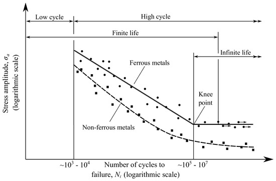
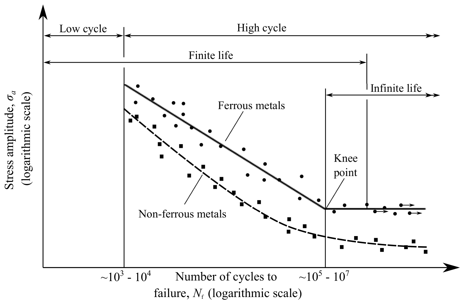
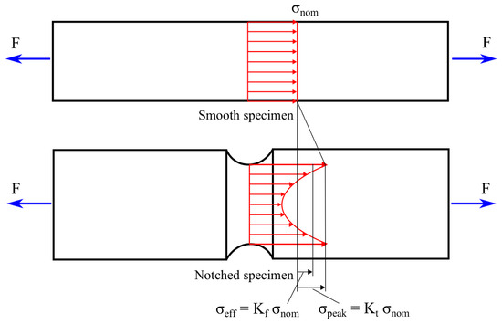
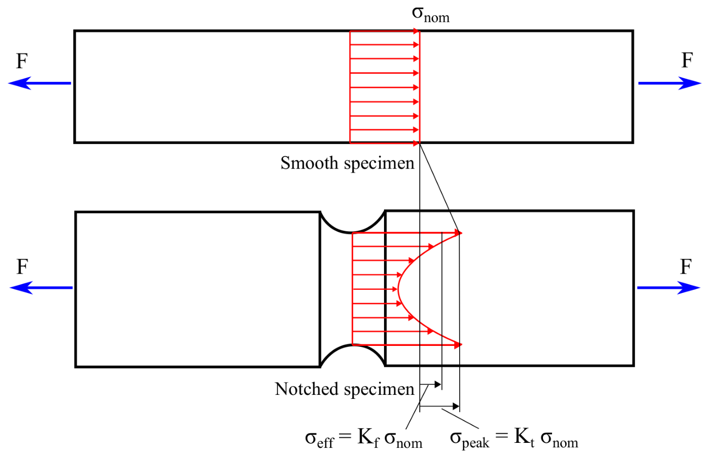
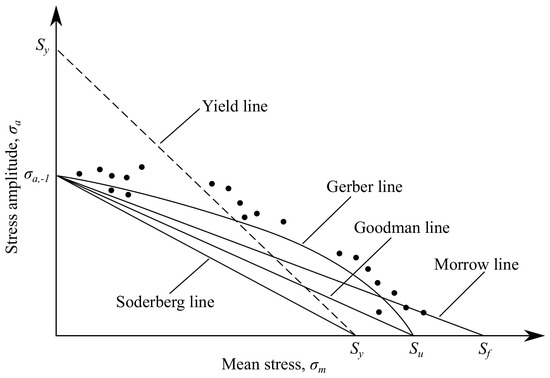
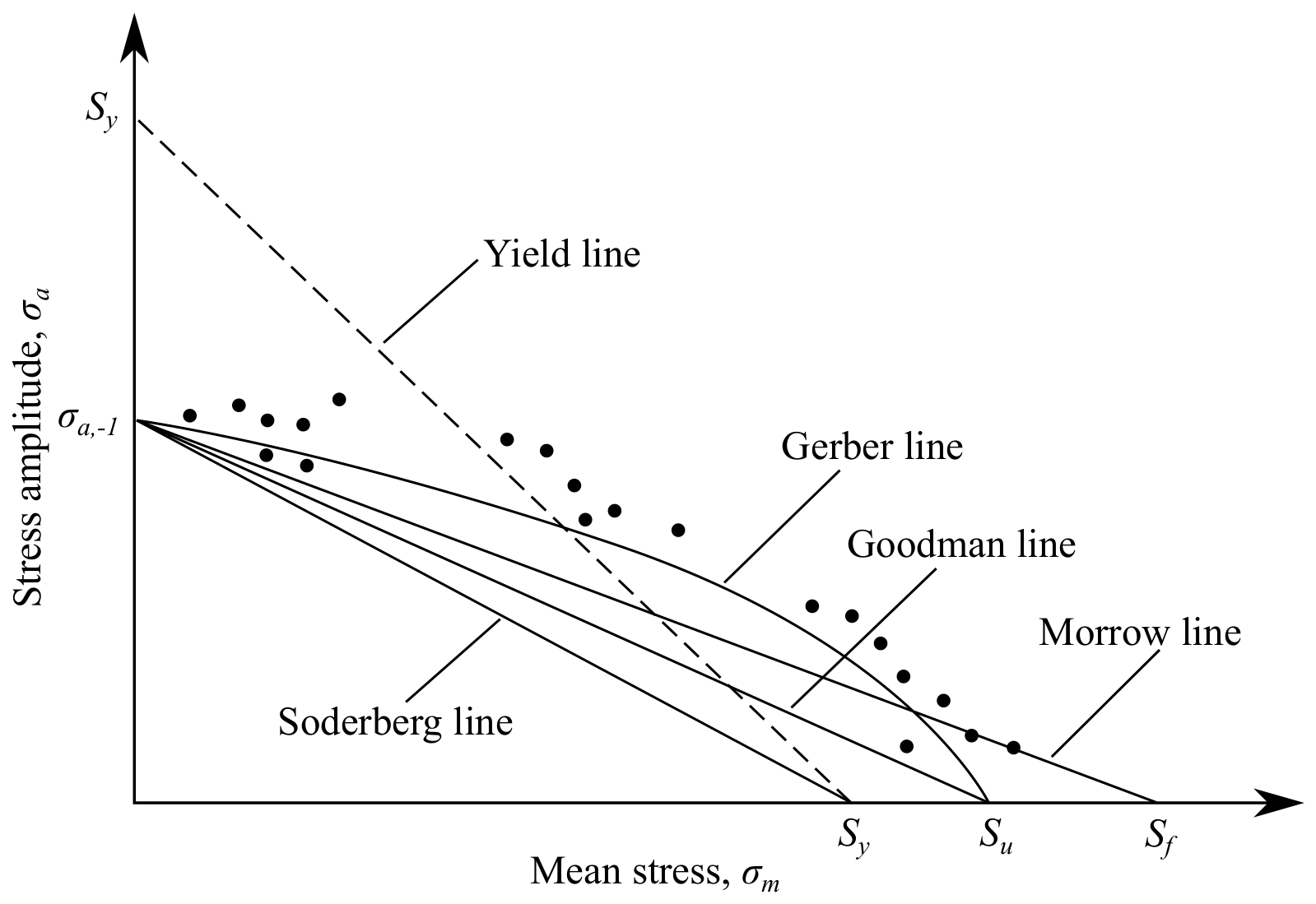
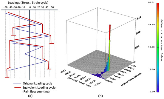
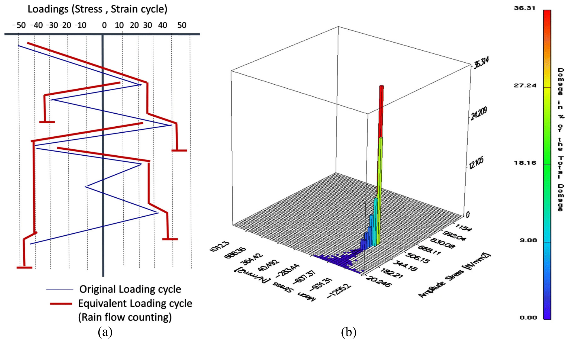
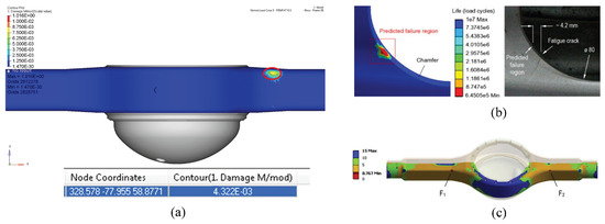
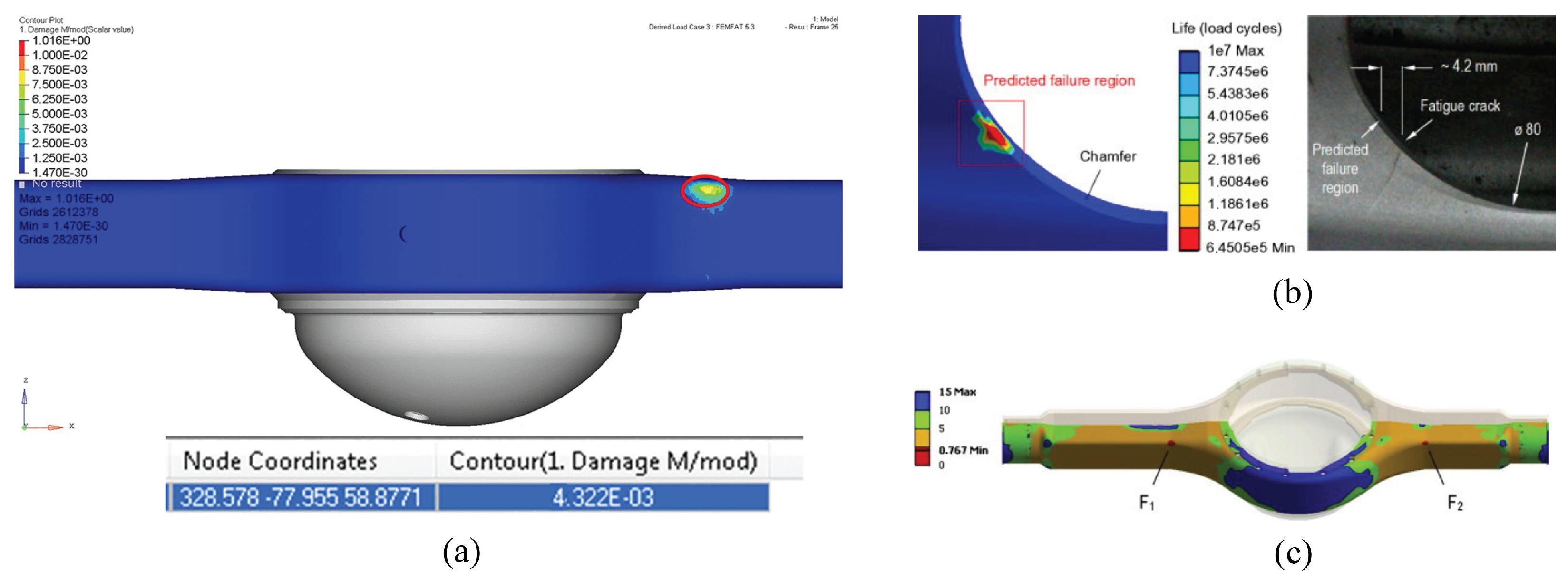
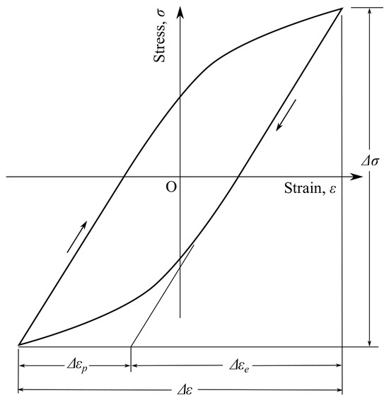
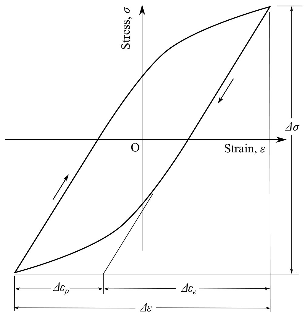
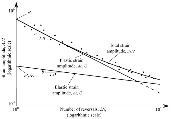
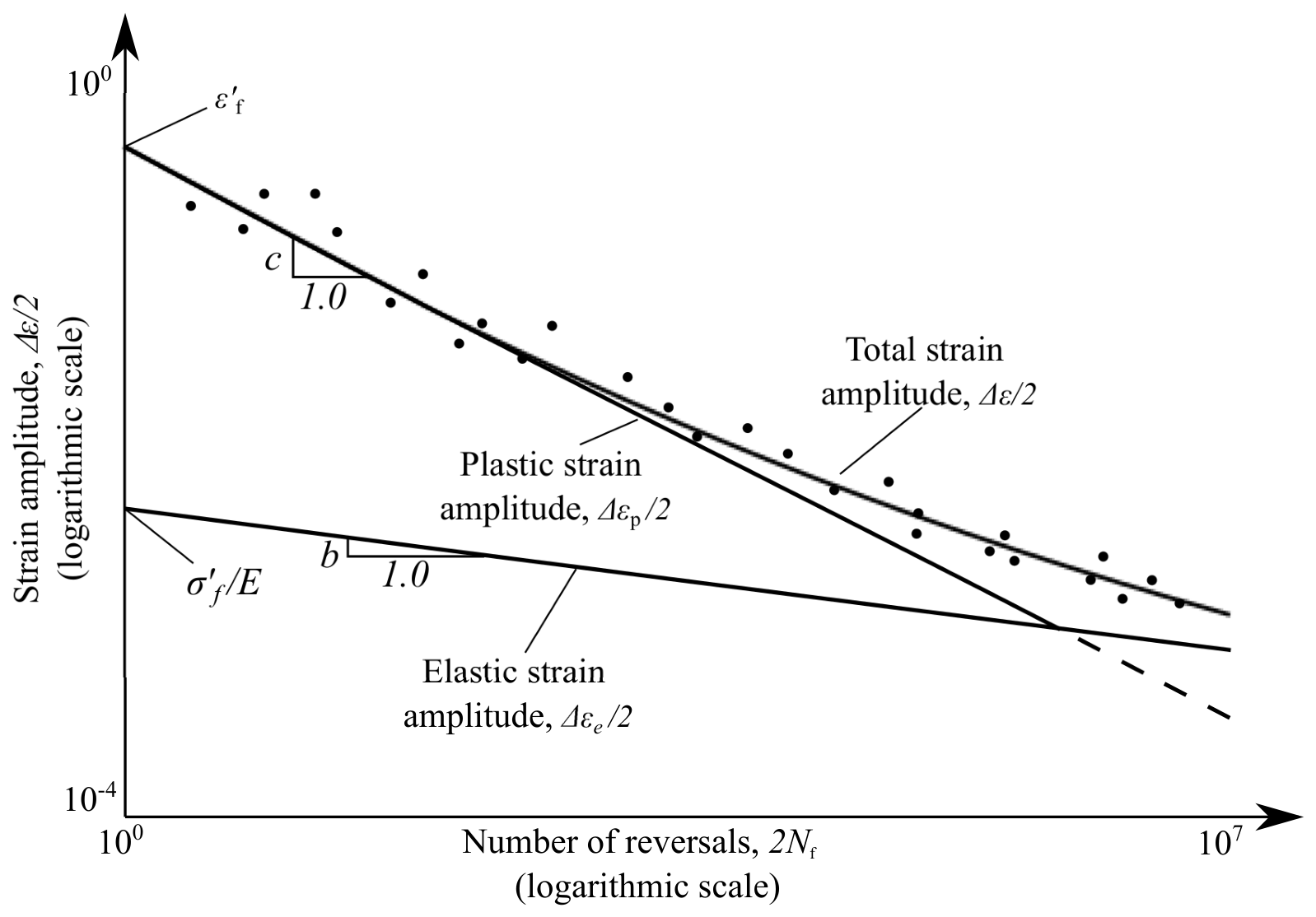
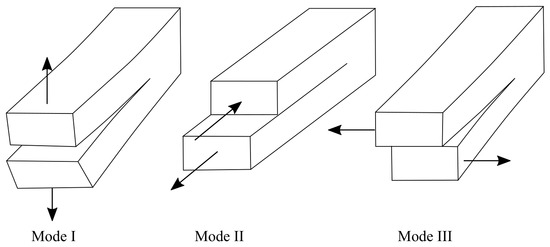
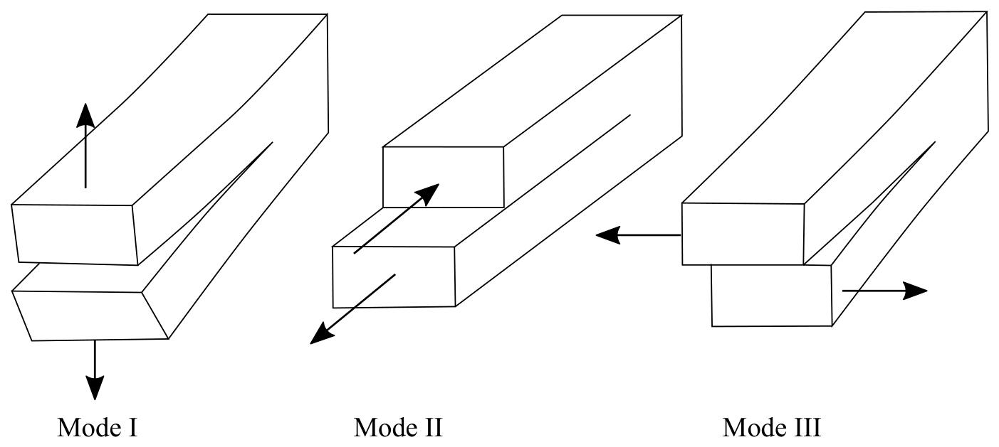
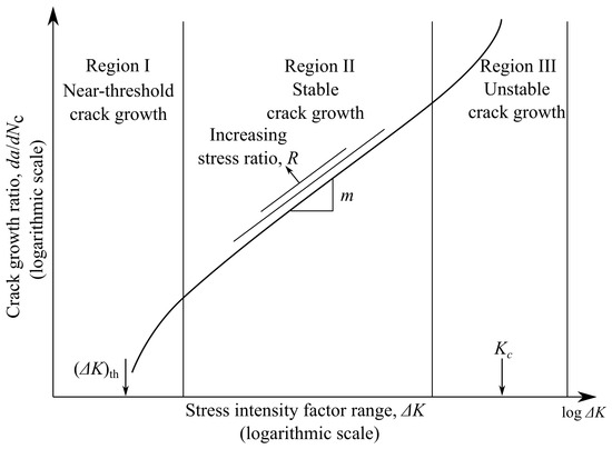
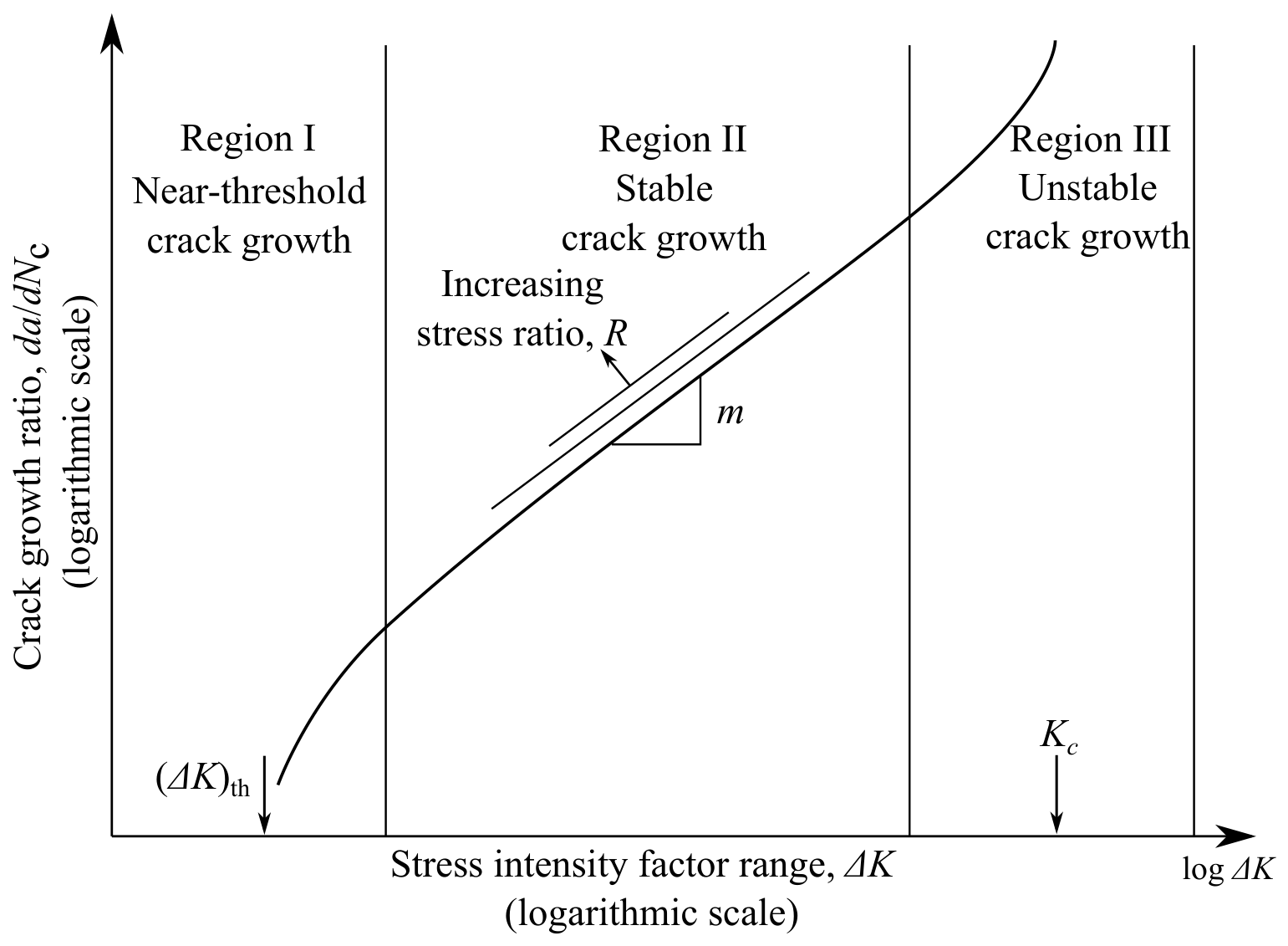
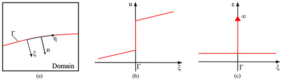
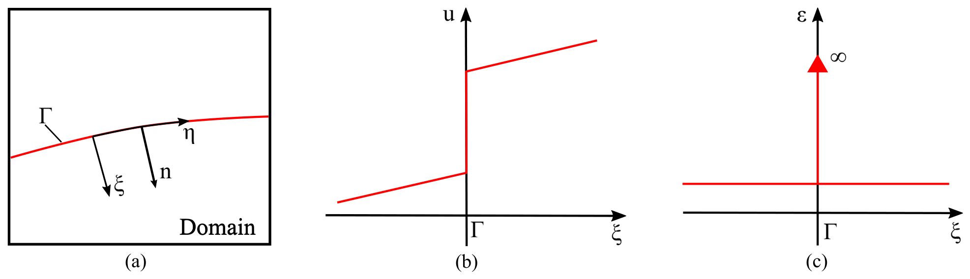
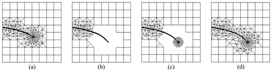
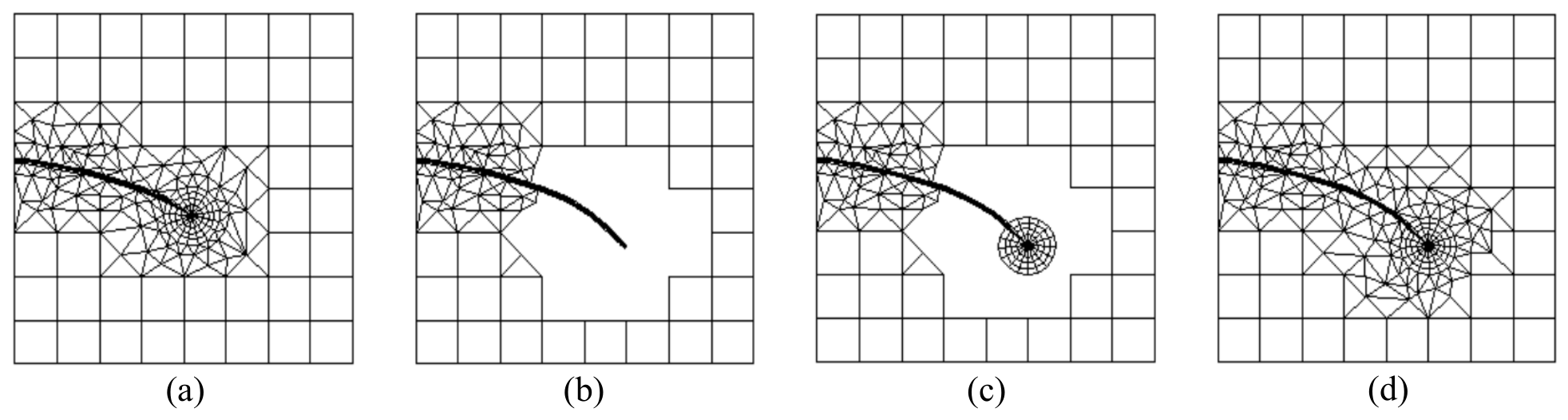
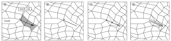
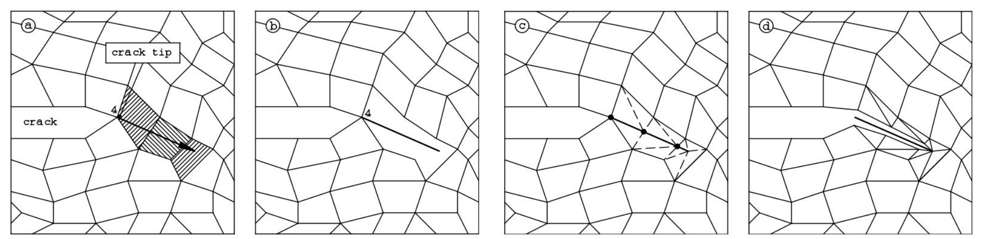
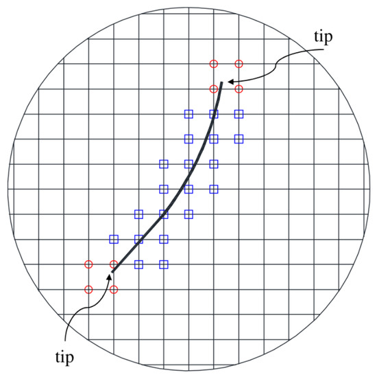
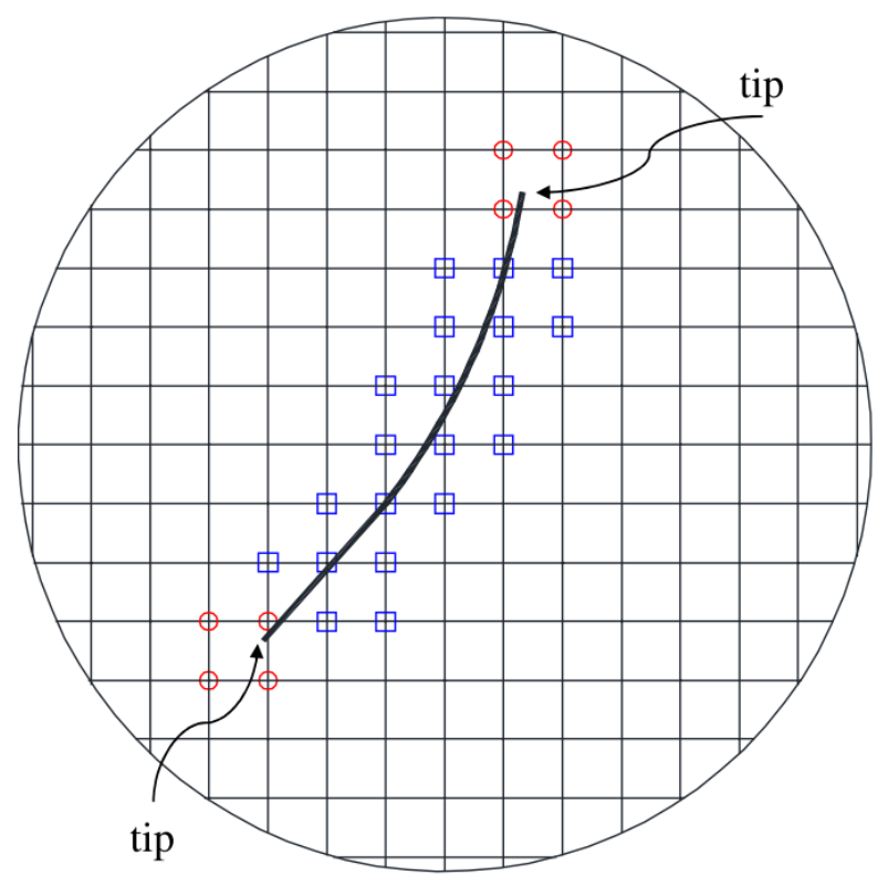
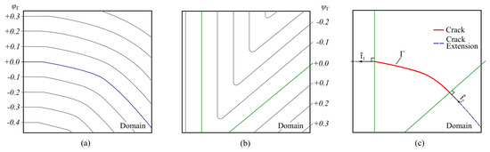
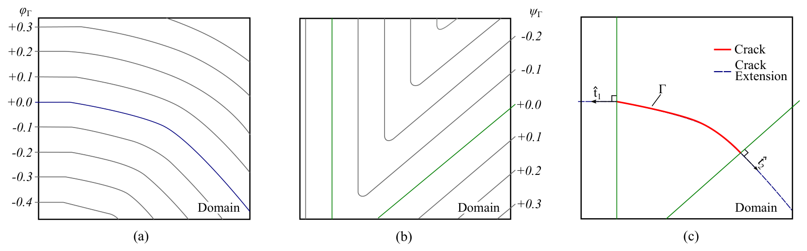
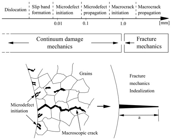
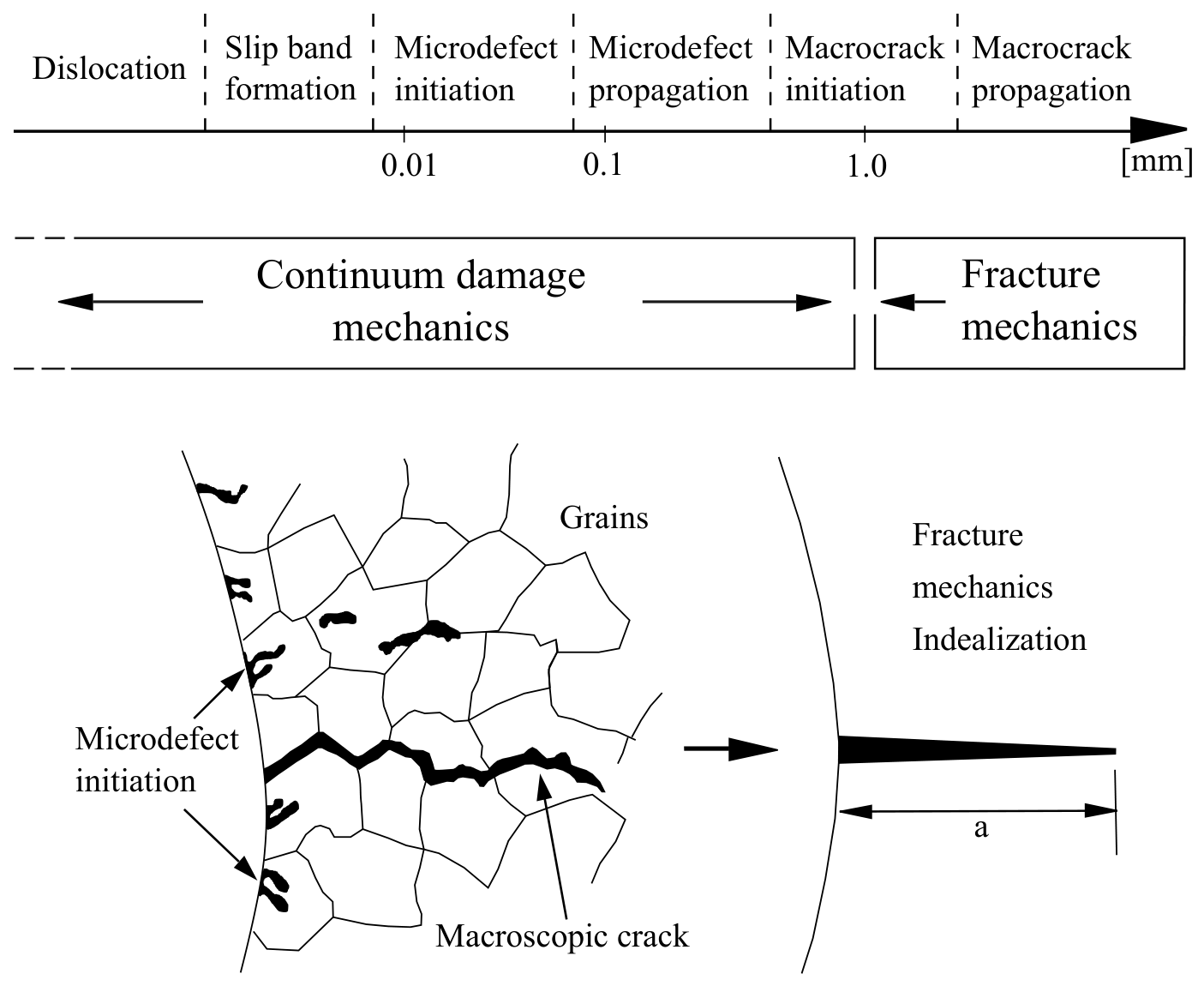
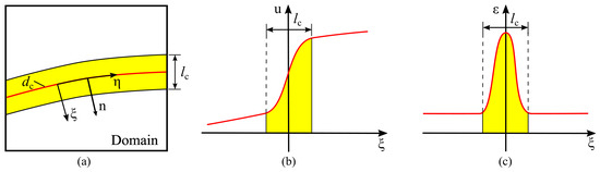
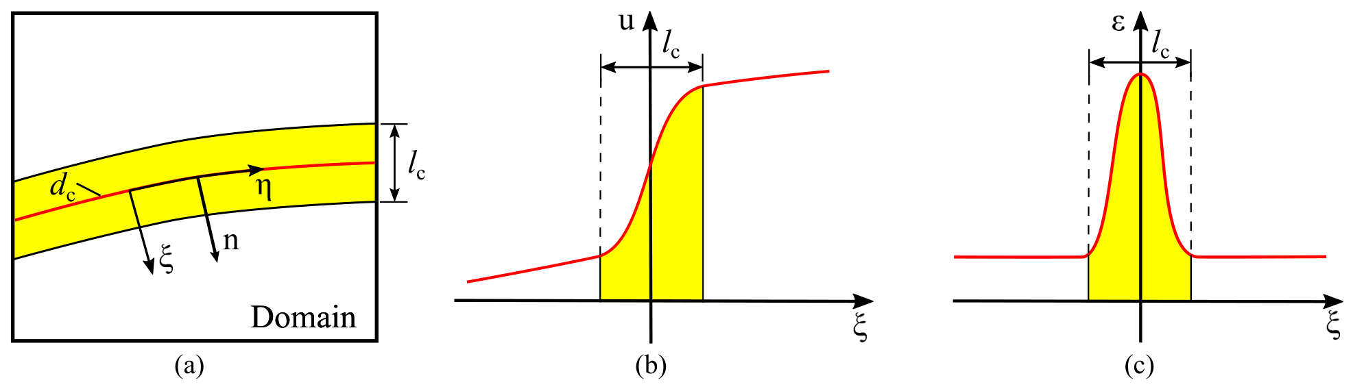
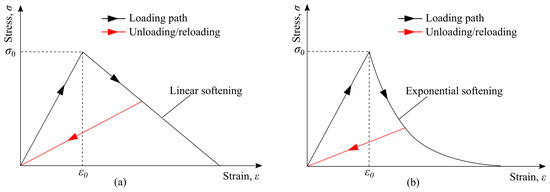
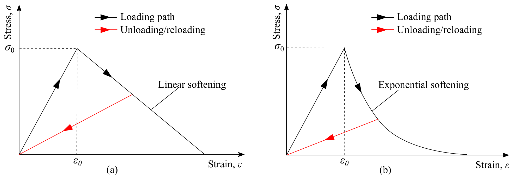
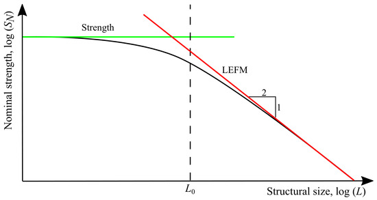
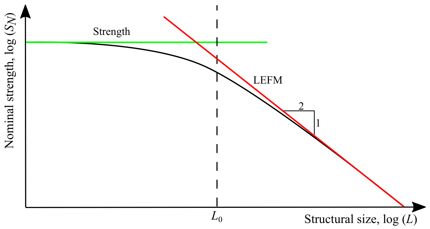
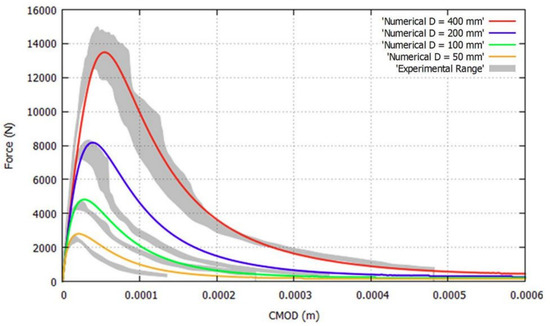
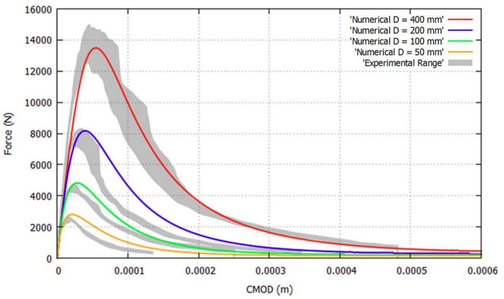
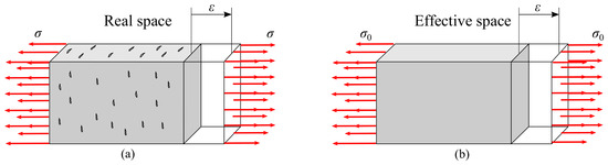
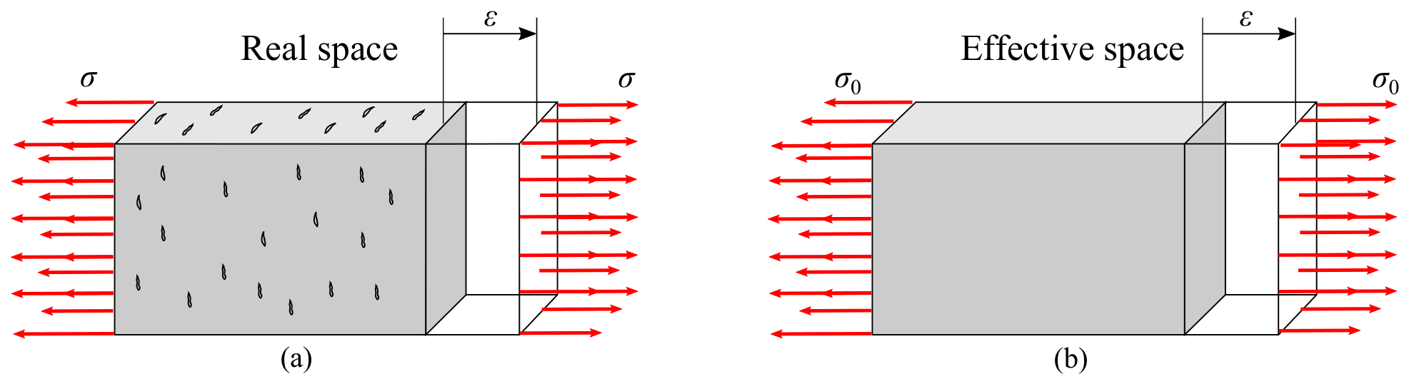
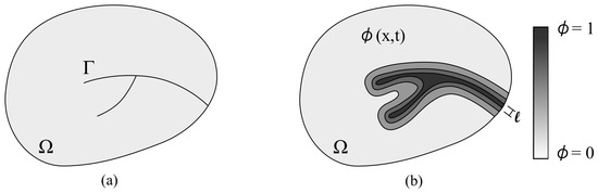
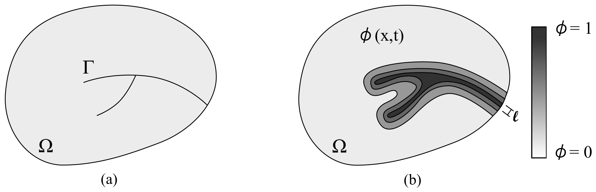
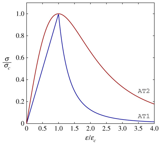
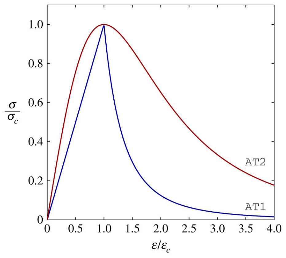
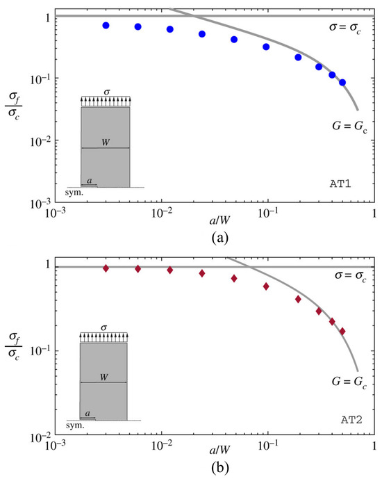
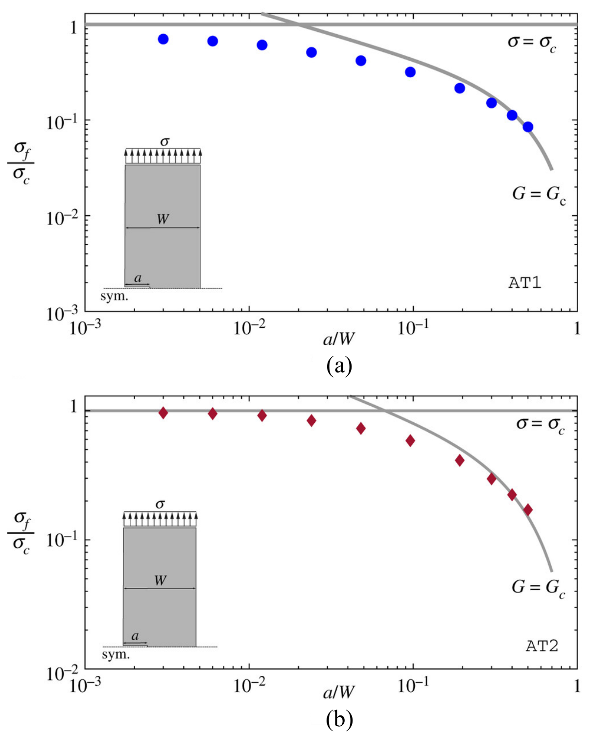
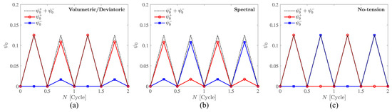
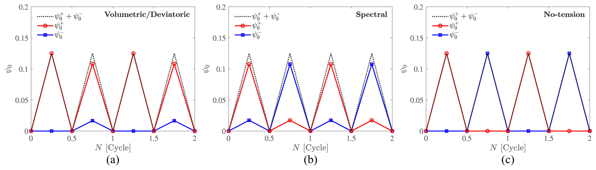
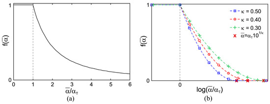
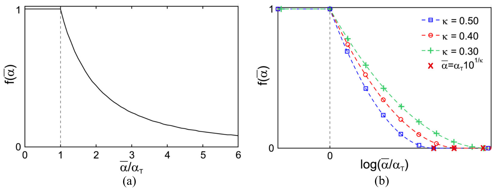
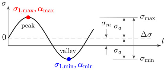
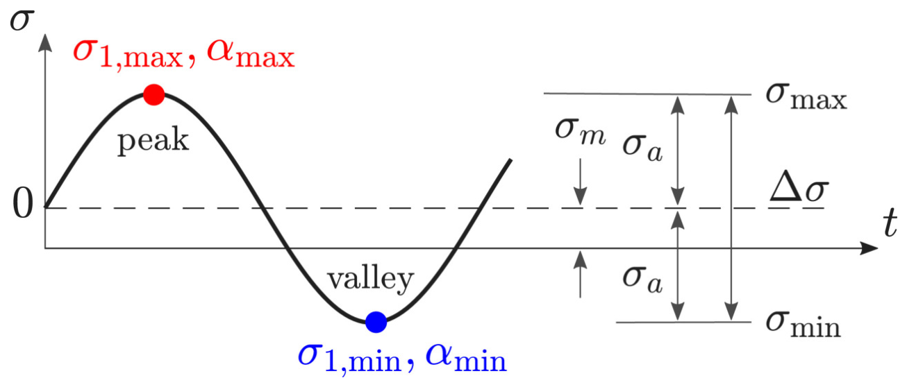
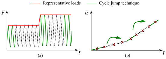
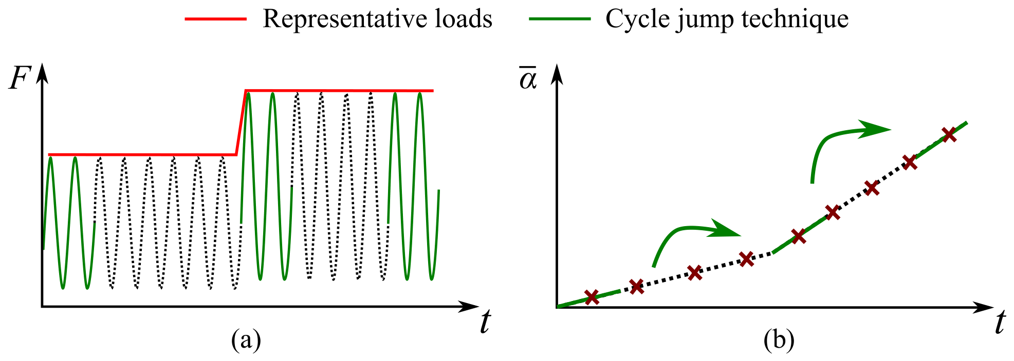
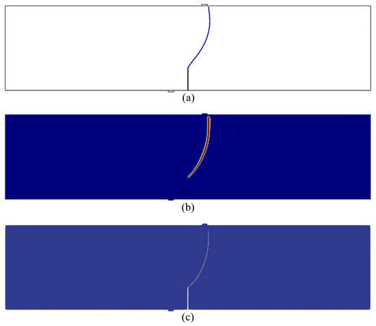
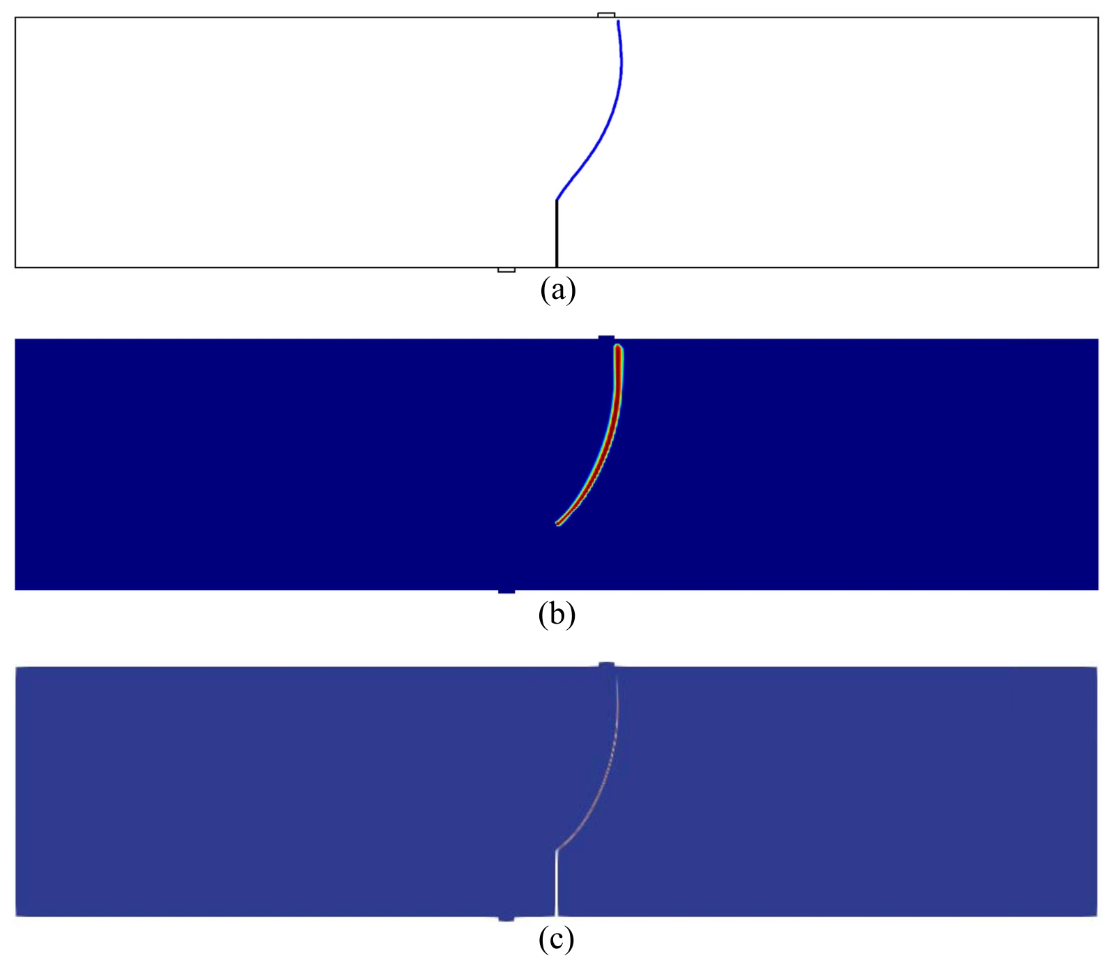

Disclaimer/Publisher’s Note: The statements, opinions and data contained in all publications are solely those of the individual author(s) and contributor(s) and not of MDPI and/or the editor(s). MDPI and/or the editor(s) disclaim responsibility for any injury to people or property resulting from any ideas, methods, instructions or products referred to in the content. |
© 2026 by the authors. Licensee MDPI, Basel, Switzerland. This article is an open access article distributed under the terms and conditions of the Creative Commons Attribution (CC BY) license.