


Abstract
This paper presents the RaDICAL sensing framework, a monostatic passive radar concept that combines a Sparse Uniform Circular Array (SUCA), deterministic multifrequency dither, and dictionary-based waveform recognition for target detection and classification. Rather than forming conventional spatial images or relying primarily on Doppler processing, RaDICAL encodes target geometry directly into a composite receiver waveform and performs hypothesis testing by matching measured signals to a library of predicted responses. This study develops the SUCA-based signal model for point and extended targets and formulates recognition as a waveform-domain matching problem against the representation dictionary using normalized complex correlation and QR-domain processing. A reproducible MATLAB-based study evaluates waveform separability, probability of detection versus dictionary SNR, physical power balance, receiver operating characteristic (ROC) behavior, and detection performance versus illuminator EIRP. The results show that deterministic dither produces distinctive composite waveforms with strong hypothesis separability. The ROC simulations characterize binary detection of the structured waveform, while the recognition simulations quantify discrimination among competing physical dictionary hypotheses. Because the proposed receiver coherently processes multiple spatial and temporal waveform samples, no direct single-sample SNR advantage over a classical matched-filter detector is claimed. These results support the feasibility of waveform-domain passive sensing using deterministic spatial–frequency encoding and dictionary-based recognition. Unlike conventional representation-learning methods that derive embeddings from image or feature datasets, the proposed waveform representations are generated deterministically from physical electromagnetic models.
Keywords:
physics-based representation learning; waveform-domain recognition; geometry-aware object recognition; dictionary-based recognition; Sparse Uniform Circular Array (SUCA); deterministic multifrequency dither; QR-domain processing; reference-free passive radar; monostatic passive radar MSC:
94A12; 68T10; 93B07
1. Introduction
The present work represents the second stage of the RaDICAL research framework. The first stage, reported in our recent Sensorspaper [1,2], established the fundamental waveform-domain sensing architecture for localization of point targets using a Sparse Uniform Circular Array (SUCA) with deterministic multifrequency dither. That work demonstrated that target range, azimuth, and elevation can be estimated directly from the composite receiver waveform without reconstructing conventional radar images or requiring a reference channel. The proposed architecture also eliminates the need for explicit carrier-phase synchronization with the noncooperative illuminator by digitally normalizing all receiver channels with respect to a common reference element, thereby suppressing transmitter-dependent phase and waveform variations while preserving the differential spatial information required for localization.
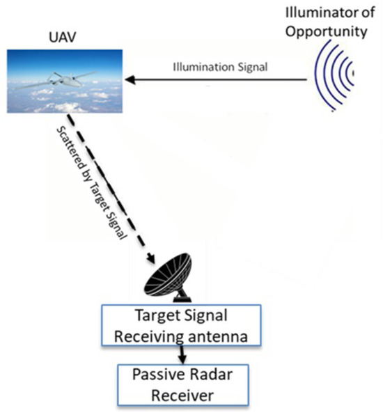
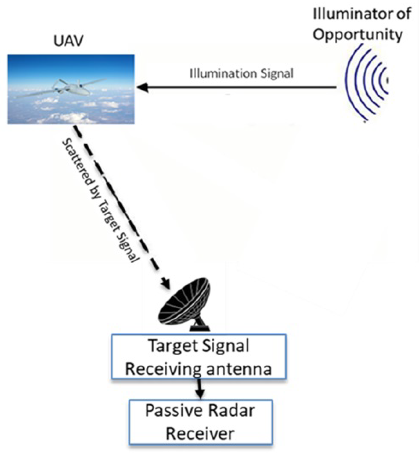
Building upon this foundation, the present paper extends the RaDICAL framework from point-target localization to physics-based waveform representation for extended objects. A conceptual overview of the complete RaDICAL representation-learning framework is shown in Figure 1. Rather than representing a target as a single scattering center, objects are modeled as collections of scattering centers whose spatial geometry generates distinctive composite waveforms. Recognition is performed by matching the measured waveform against a physics-based dictionary of predicted object responses, shifting the emphasis from point-target localization toward deterministic waveform representations and geometry-aware object recognition. This extension transforms the original localization framework into a unified sensing architecture capable of both precise point-target localization and recognition of complex extended objects within the same waveform-domain formulation.
Figure 1.
Conceptual overview of the RaDICAL monostatic passive radar architecture.
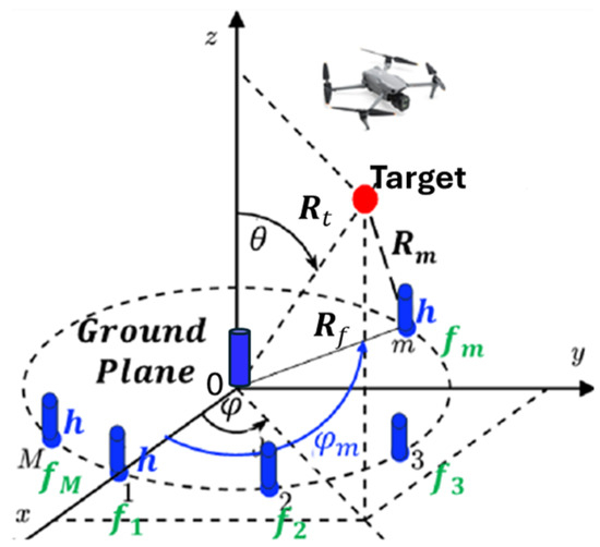
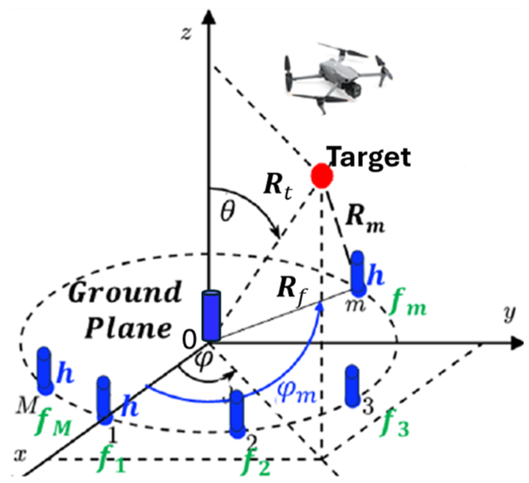
The key hardware element of the RaDICAL framework is the Sparse Uniform Circular Array (SUCA), illustrated in Figure 2. A circular geometry is adopted to provide an intrinsic field of view, thereby providing uniform azimuthal coverage. Throughout this paper, the SUCA is assumed to consist of 11 receiving elements uniformly distributed on a circular ring of radius together with one central reference element, denoted Element0, for a total of 12 receiving elements. All elements are low-gain receiving antennas, such as vertical monopoles or patch antennas above a ground plane. The ring radius is chosen so that the spacing between adjacent ring elements is approximately one wavelength. This sparse geometry reduces mutual coupling, allows the individual elements to operate nearly independently, and provides sufficient spatial diversity for deterministic waveform generation while maintaining a compact receiver aperture.
Figure 2.
SUCA geometry with deterministic multifrequency dither.
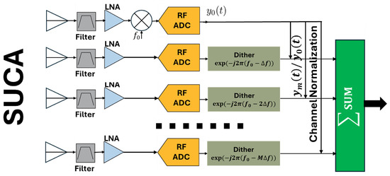
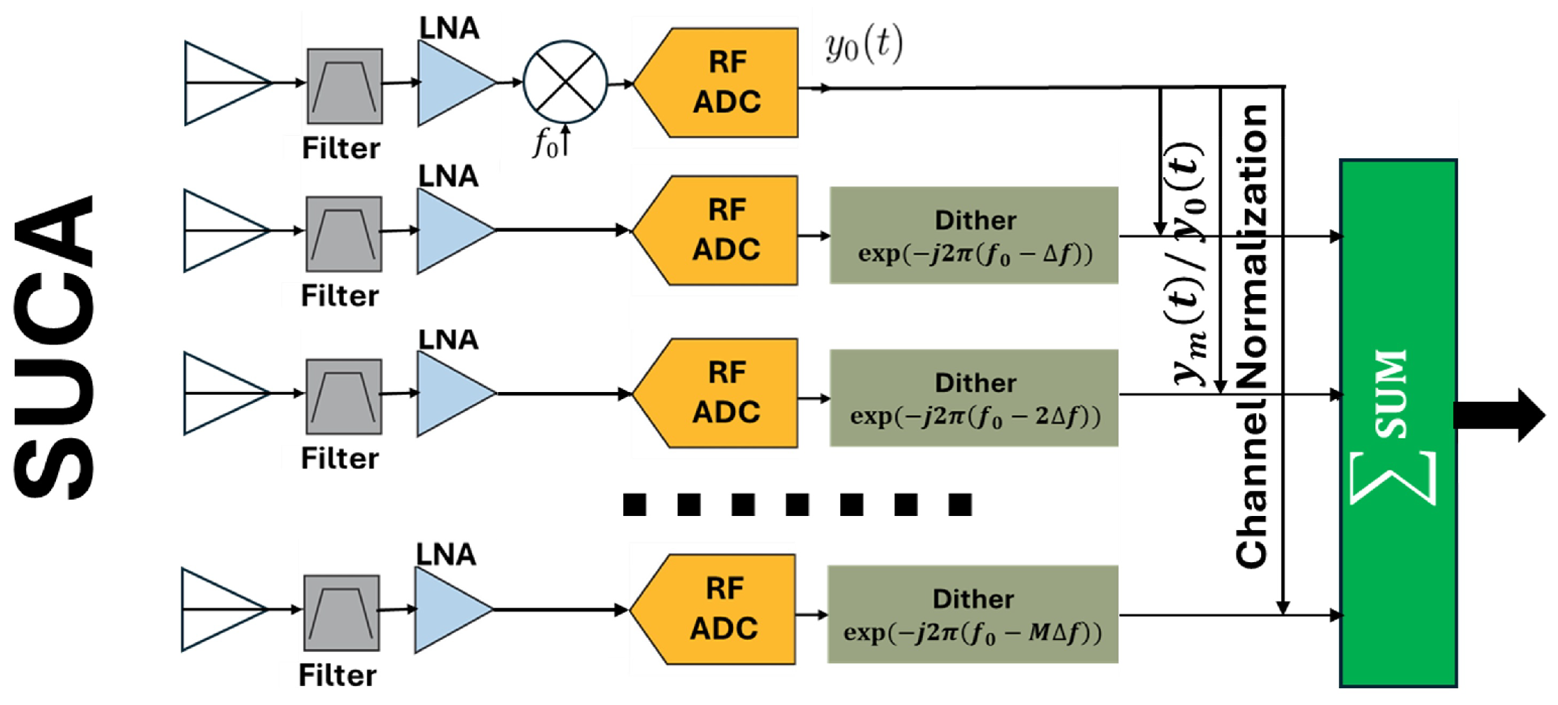
Signals received by the individual SUCA elements are independently digitized and processed according to the receiver architecture shown in Figure 3. A deterministic multifrequency dither is applied across the receiver channels so that the spatial information contained in the incident wavefront is transformed into a composite waveform with a distinctive temporal and phase structure. Rather than forming a conventional spatial image, the receiver directly generates a physics-based waveform representation whose structure is uniquely determined by the target geometry.
Figure 3.
RaDICAL receiver architecture showing SUCA element channels, deterministic multifrequency dither, Element0 normalization , and formation of the composite waveform .
Within this framework, object recognition is formulated as a representation-learning problem in waveform space. Instead of learning representations from large labeled datasets, the waveform dictionary is generated deterministically from the underlying electromagnetic signal model. Each dictionary entry corresponds to a predicted composite waveform associated with a particular target geometry or object class. The measured waveform is compared with these predicted representations using normalized complex correlation and QR-domain processing. This physics-based dictionary naturally supports point-target localization, extended-target recognition, and geometry-aware object classification within a unified mathematical framework.
The present paper develops and validates this representation-learning framework using a reproducible MATLAB-based study. First, a SUCA signal model is developed for both point and extended targets under deterministic frequency diversity. Binary target images are then converted into waveform-domain dictionary entries that serve as deterministic object representations. Recognition is subsequently performed directly in waveform space without intermediate image reconstruction. The resulting framework is evaluated through waveform dictionary separability together with several complementary performance metrics, including probability of detection versus dictionary SNR, physical power-balance analysis, detection probability versus physical SNR, receiver operating characteristic (ROC) behavior, and detection performance versus illuminator EIRP.
A central result of this work is that recognition performance is governed primarily by the information content of the waveform representation rather than by nominal signal-to-noise ratio alone. The results demonstrate that deterministic spatial–frequency encoding combined with physics-based waveform representations enables robust recognition at low physical SNR while providing a mathematically interpretable alternative to conventional data-driven representation learning.
The remainder of this paper is organized as follows. Section 2 reviews related work in passive radar, reference-free sensing, and physics-based representation learning. Section 3 develops the physics-based waveform representations generated by the RaDICAL framework for both point and extended targets. Section 4 introduces waveform-domain representation learning based on deterministic physics-based dictionaries. Section 5 investigates the separability of the resulting waveform representations. Section 6 validates the proposed framework using multiple complementary performance metrics, including detection probability versus dictionary SNR, physical power-balance analysis, detection probability versus physical SNR, receiver operating characteristic (ROC) analysis, and detection performance versus illuminator EIRP. Finally, Section 6 summarizes the main conclusions and outlines directions for future research.
Related Work and Physics-Based Representation Learning
Passive radar has evolved from a detection technology into a broader sensing framework capable of localization, imaging, and target recognition using illuminators of opportunity [3]. Aircraft detection and tracking using FM-radio-based passive radar have been demonstrated in operationally relevant scenarios [4,5,6], while broader tutorial treatments have traced the evolution of passive radar from detection to imaging applications [7]. Passive synthetic aperture techniques have further extended these capabilities by enabling image formation and velocity estimation for moving targets illuminated by noncooperative transmitters [8,9], although such methods generally rely on target motion and extended coherent integration intervals.
Related multichannel radar architectures include colocated and widely separated MIMO radar configurations [10,11]. A comprehensive treatment of passive radar principles and architectures is given in [3].
Several studies have investigated passive radar imaging and target recognition using noncooperative transmitters. Lanterman [12] presented early concepts of passive radar imaging and recognition, highlighting the challenges associated with reference signal availability and waveform uncertainty. More recent work has focused on efficient passive radar signal processing algorithms, improved numerical conditioning, and computational efficiency [13]. Comprehensive surveys have also emphasized the growing importance of passive sensing for UAV detection and monitoring in increasingly congested spectral environments [14].
A distinct line of research has explored reference-free passive sensing architectures. Brennan et al. [15] demonstrated reference-free passive RF imaging in the near field using dense spatial sampling and aperture-based processing, eliminating the need for a direct-path reference signal. Related work has investigated reference-free WiFi radar for monitoring people and drones [16], where spatial diversity and environmental scattering replace explicit reference-channel reconstruction. Although these approaches successfully eliminate the reference antenna, they generally rely on dense apertures, near-field assumptions, or spatial image formation.
Collectively, these studies demonstrate continuous progress in passive radar sensing, from detection and localization to imaging and target recognition. However, most existing approaches still formulate the recognition problem in the spatial or image domain, where object representations are reconstructed from measured data before classification.
In contrast, the RaDICAL framework formulates recognition directly in waveform space. Rather than reconstructing an intermediate image, the received signal is compared with deterministic waveform representations generated from the underlying electromagnetic model. Consequently, the dictionary is derived from physics rather than learned from labeled training data. This representation-learning paradigm is complementary to conventional data-driven approaches and provides a mathematically interpretable framework in which recognition is performed through hypothesis testing in waveform space.
Recent advances in pattern recognition have been dominated by representation-learning methods in which feature representations are learned statistically from large annotated datasets [17]. Dictionary learning and sparse representations have further demonstrated the importance of compact signal representations for recognition and classification tasks [18]. More recently, physics-informed learning has emerged as a complementary paradigm that incorporates governing physical models into the learning process rather than relying solely on data-driven optimization [19]. The RaDICAL framework follows a related but distinct philosophy. Instead of learning object representations from training data, it generates deterministic waveform representations directly from electromagnetic wave propagation and receiver geometry. Object recognition is then formulated as hypothesis testing in waveform space using a physics-based dictionary of predicted responses.
2. Generation of Physics-Based Waveform Representations
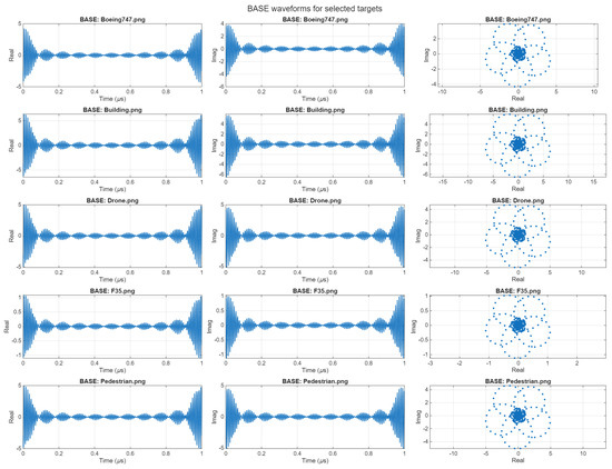
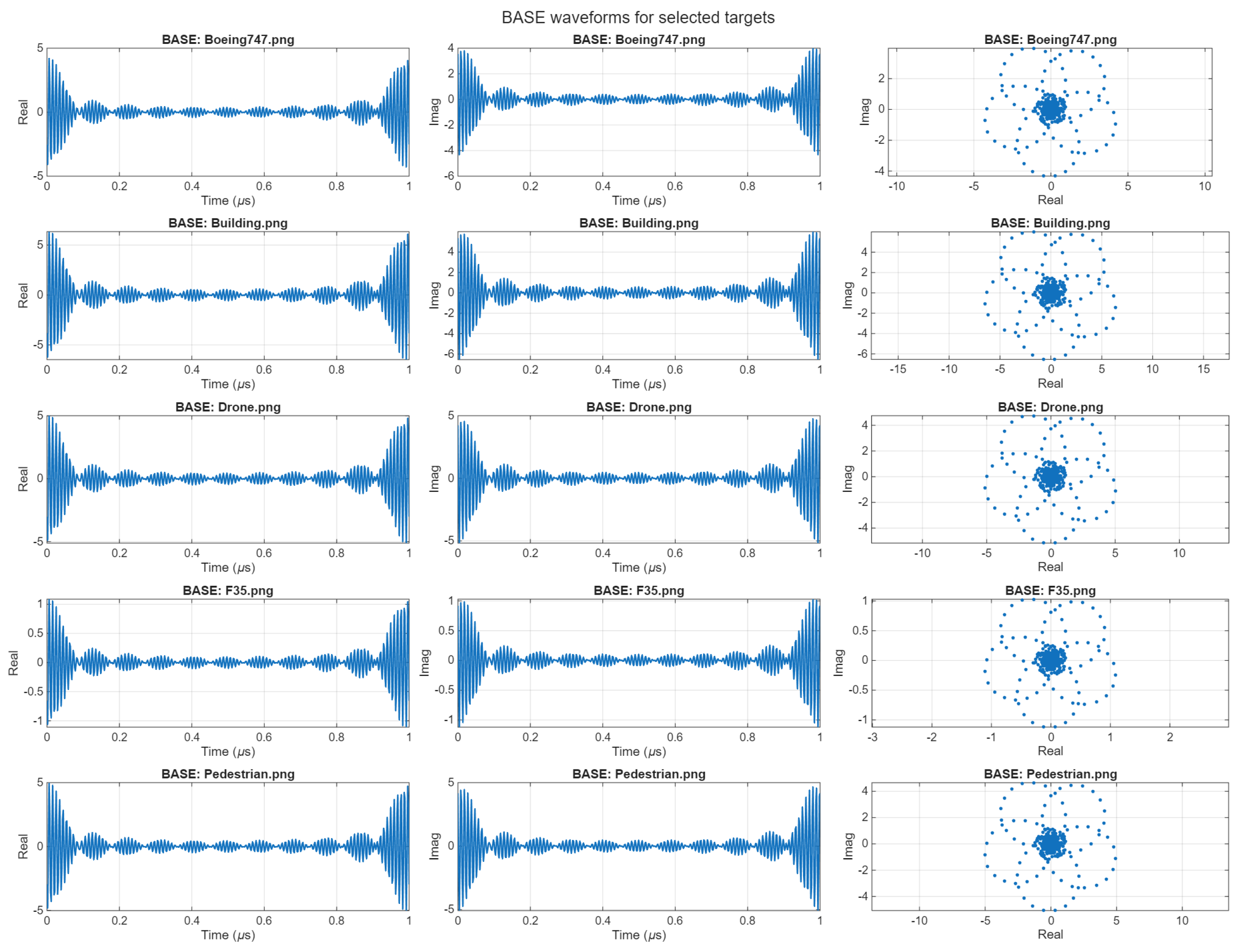
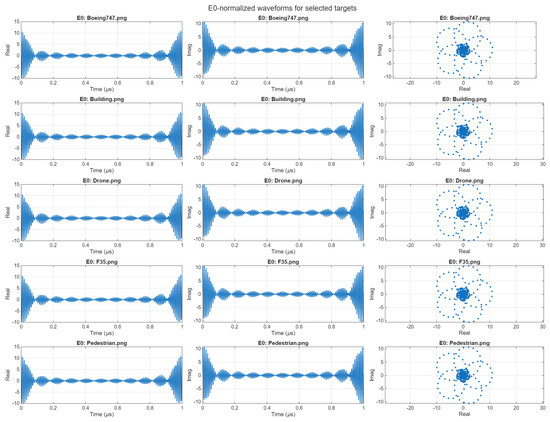
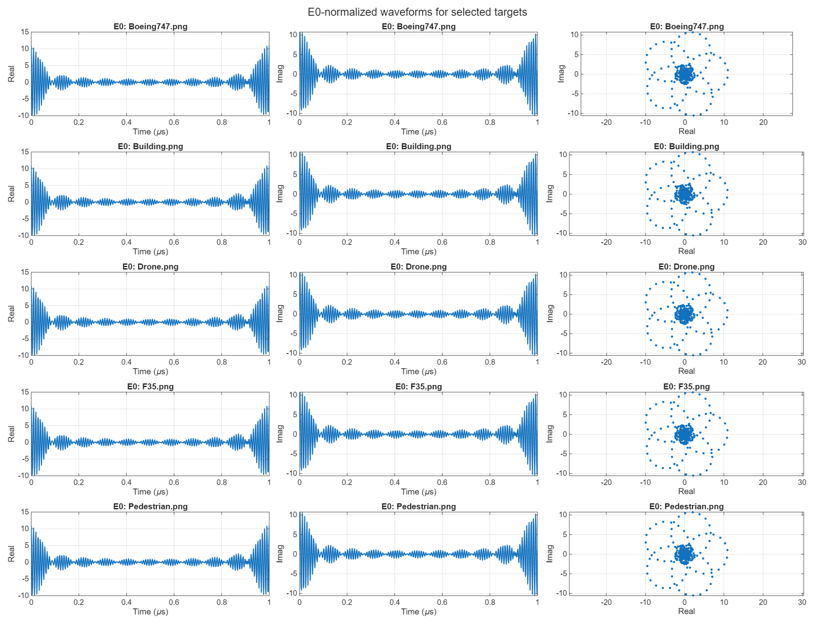
The representative object library used throughout this paper is shown in Figure 4. For each object hypothesis, electromagnetic propagation through the SUCA receiver produces a unique composite waveform that serves as a deterministic physics-based representation of the object geometry. Representative waveform representations generated using the baseline (BASE) receiver formulation and the Element0-normalized formulation are presented in Figure 5 and Figure 6, respectively. Even by visual inspection, the composite waveforms associated with different object hypotheses exhibit distinct trajectories in the complex plane, indicating that the SUCA encoding transforms object geometry into unique waveform signatures. The quantitative separability of these waveform representations is investigated in the following section using correlation analysis.
Figure 4.
Representative target images used to construct the object dictionary. From left to right: top row—Boeing 747, building, drone; bottom row—F–35 fighter jet, pedestrian.
Figure 5.
Composite SUCA waveforms for several representative targets generated using the baseline (BASE) formulation without element normalization. Each row corresponds to a different target from the image library.
Figure 6.
Composite SUCA waveforms for the same targets after Element0 (E0) normalization.
Assuming SUCA element independence and according to Figure 2, the signal received by the mth SUCA element can be written as
where , is the wavenumber corresponding to the carrier frequency , is the element pattern, and c is the speed of light. The common complex envelope is modeled as
where represents the illuminating transmitter modulation and common propagation amplitude, is the complex target scattering coefficient, is the common Doppler frequency, and denotes the transmitter phase instability. Thus, contains all multiplicative terms shared by the SUCA channels.
For a point target located at slant range , azimuth , and elevation , the distance between the target and the mth element is
where the angular position of each element is
According to the receiver block diagram shown in Figure 3, the signal received by each SUCA element is digitized, while the Element0 signal is additionally downconverted to baseband,
Meanwhile, in the remaining channels a deterministic multifrequency dither shifts the carrier frequency according to the SUCA element index, , where is the frequency step (chosen as ). The resulting signals can be written as
Here, denotes the digitally imposed deterministic dither frequency associated with the mth channel after digitization.
For this point-target case, all multiplicative terms contained in the common factor are canceled by Element0 normalization. These terms include the transmitter modulation, common Doppler modulation, target scattering coefficient, and transmitter phase instability. Consequently, the normalized waveform preserves the differential spatial information determined by the SUCA geometry while removing common illumination terms.
Since the Element0 signal is downconverted to baseband entirely in the digital domain, the normalization is performed after digitization. Conventional receiver-channel calibration, including gain, phase, and delay alignment, is therefore applied prior to normalization.
For a point target, the corresponding composite RaDICAL waveform is
For an extended object, however, each physical SUCA channel receives the coherent sum of the signals produced by all scattering centers. Therefore, Element0 normalization is applied only after the complete extended-target waveform has been formed in each receiver channel. Let the object consist of L scattering centers with locations and complex reflectivities . The complete waveform in the mth SUCA channel is
while the complete Element0 waveform is
The physically realizable Element0 normalization is then
Finally, the extended-target composite waveform is formed as
Thus, the coherent summation over all scattering centers is performed first in each physical receiver channel, followed by Element0 normalization of the resulting complete channel waveforms. This processing order corresponds directly to the realizable receiver architecture and to the revised numerical implementation used in the extended-target simulations.
Thus, both the target location and its spatial structure are encoded directly into the composite waveform , which serves as the deterministic physics-based waveform representation used throughout the remainder of this paper for waveform-domain recognition.
Figure 5 and Figure 6 illustrate representative physics-based waveform representations generated using the baseline formulation and the Element0-normalized formulation, respectively. In the complex plane, the waveform representations corresponding to different targets follow distinct trajectories, illustrating the separability of the deterministic representation space. Element0 normalization suppresses common illumination terms while preserving the differential spatial phase structure generated by the SUCA geometry.
It is worth noting that the SUCA dwell time is determined by the deterministic dither frequency step and equals 1 μs = 1/Δf. Over such a short observation interval, the temporal variations associated with the common factor are almost negligible.
3. Waveform-Domain Physics-Based Waveform Representation
Recognition in the RaDICAL framework is performed directly in waveform space using deterministic waveform representations generated by the signal model developed in the previous section. For each object hypothesis , define
The collection of K predicted waveform representations forms the physics-based representation dictionary
Sampling each waveform at produces the representation matrix
whose columns represent deterministic waveform embeddings of the corresponding object hypotheses. Similarly, the measured waveform
is obtained from the extended-object model (12).
For efficient processing, the representation matrix is orthogonalized
where the columns of form an orthonormal basis for the representation space. The measured waveform and each physical dictionary hypothesis are represented in the same orthogonal Q-basis as
Recognition is performed entirely in this orthogonal basis using the normalized complex correlation
The recognized object corresponds to
Since each physical dictionary waveform belongs to the column space of , The QR transformation therefore preserves the normalized-correlation decision and does not by itself provide additional detection gain. The observed performance is instead determined by coherent processing of the structured waveform samples and by the separability of the physical waveform dictionary.
Multiple representation dictionaries can be generated offline for different operational scenarios, object classes, environmental conditions, or sensing geometries. During operation, the RaDICAL processor loads only the subset of waveform representations required for the current sensing task. Since all dictionary entries are generated directly from the underlying electromagnetic model, new object hypotheses or operating conditions can be incorporated simply by regenerating the corresponding waveform representations without modifying either the receiver architecture or the recognition algorithm. The short SUCA dwell time (1 μs in the present implementation) enables rapid acquisition of statistically independent waveform observations, facilitating efficient refinement and adaptation of the representation dictionary as additional measurements become available.
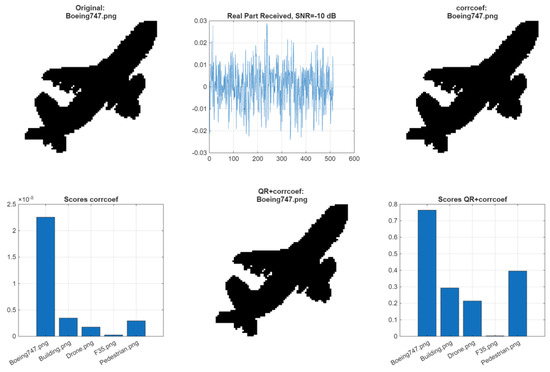
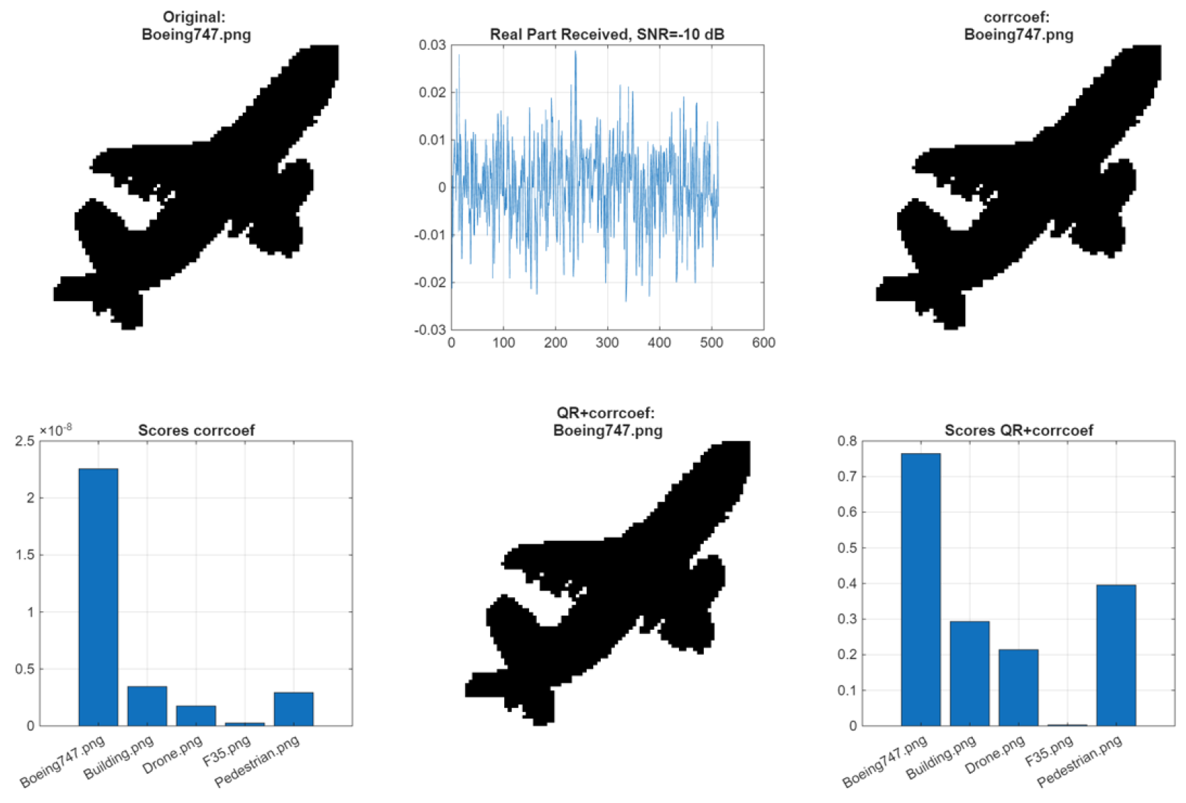
Figure 7 illustrates the waveform-domain recognition process for a noisy Boeing 747 measurement. The correct object hypothesis produces the dominant QR-based normalized-correlation response, allowing the corresponding clean contour model to be retrieved directly from the dictionary.
Figure 7.
Illustration of RaDICAL waveform recognition. Top left: binary template of the Boeing 747 target used in the dictionary. Top center: real part of the received composite waveform at . Bottom left: correlation scores obtained using conventional corrcoef matching across several dictionary hypotheses. Bottom right: scores obtained using the proposed QR + normalized correlation detector, where the correct hypothesis (Boeing 747) produces the dominant response and the corresponding clean target template can be identified from the dictionary despite the noisy received waveform.
4. Separability of Waveform Representations
4.1. Silhouette and Contour Representations
Two complementary object representations are considered in this work. The first is the silhouette representation, in which every pixel belonging to the object is modeled as an individual scattering center. The corresponding waveform representation is generated directly from the extended-object model of (12). This representation preserves the complete binary object silhouette. However, neighboring scattering centers are often separated by electrically small distances relative to the operating wavelength. Consequently, their waveform contributions can be strongly correlated, introducing substantial redundancy into the resulting object representation. The larger number of scattering centers also increases the computational cost of waveform generation and dictionary construction.
The second representation is contour-based, where only pixels located on the object boundary are modeled as scattering centers. This greatly reduces the number of scattering centers while retaining the principal geometric structure of the object. Under the equal-weight scattering-center model used in the present numerical study, the contour representation also produces substantially better waveform-domain separability than the filled silhouette for several of the investigated targets.
The improved performance should not be interpreted as implying that physical scattering occurs only at the object boundary. Rather, the contour representation serves as a sparse geometric approximation of the extended target. Such a representation is also qualitatively consistent with the fact that strong electromagnetic scattering from practical objects is often associated with edges, corners, and other geometric discontinuities.
For these reasons, the contour representation is adopted as the principal target model in the following recognition-performance study, while the silhouette representation is retained as a sensitivity comparison.
4.2. Image-Domain Representation Separability
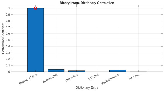
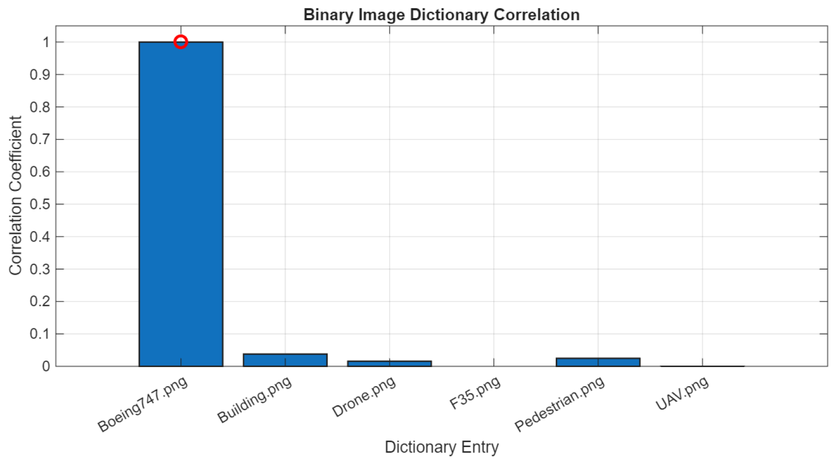
Figure 8 illustrates the correlation between binary contour representations before waveform encoding. Each bar represents the correlation coefficient (MATLAB corrcoef) between the reference image and every other object representation in the absence of noise. The Boeing 747 contour is selected as the reference and is indicated by the red marker. The low cross-correlation values confirm that the selected object representations are intrinsically distinct in the image domain.
Figure 8.
Image-domain correlation between binary dictionary images. Each bar represents the standard correlation coefficient (corrcoef) between a reference image and all other dictionary entries in the absence of noise. The Boeing 747 image is selected as the reference and is indicated by a red circle.
4.3. Waveform Representation Separability
After SUCA encoding, each object hypothesis produces a deterministic waveform representation according to (12). The separability of the waveform representation space is evaluated using the normalized complex correlation
where denotes the complex inner product over the dwell interval. Low cross-correlation values indicate that the waveform representations generated by different object hypotheses remain well separated in the representation space.
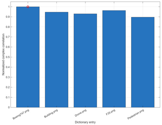
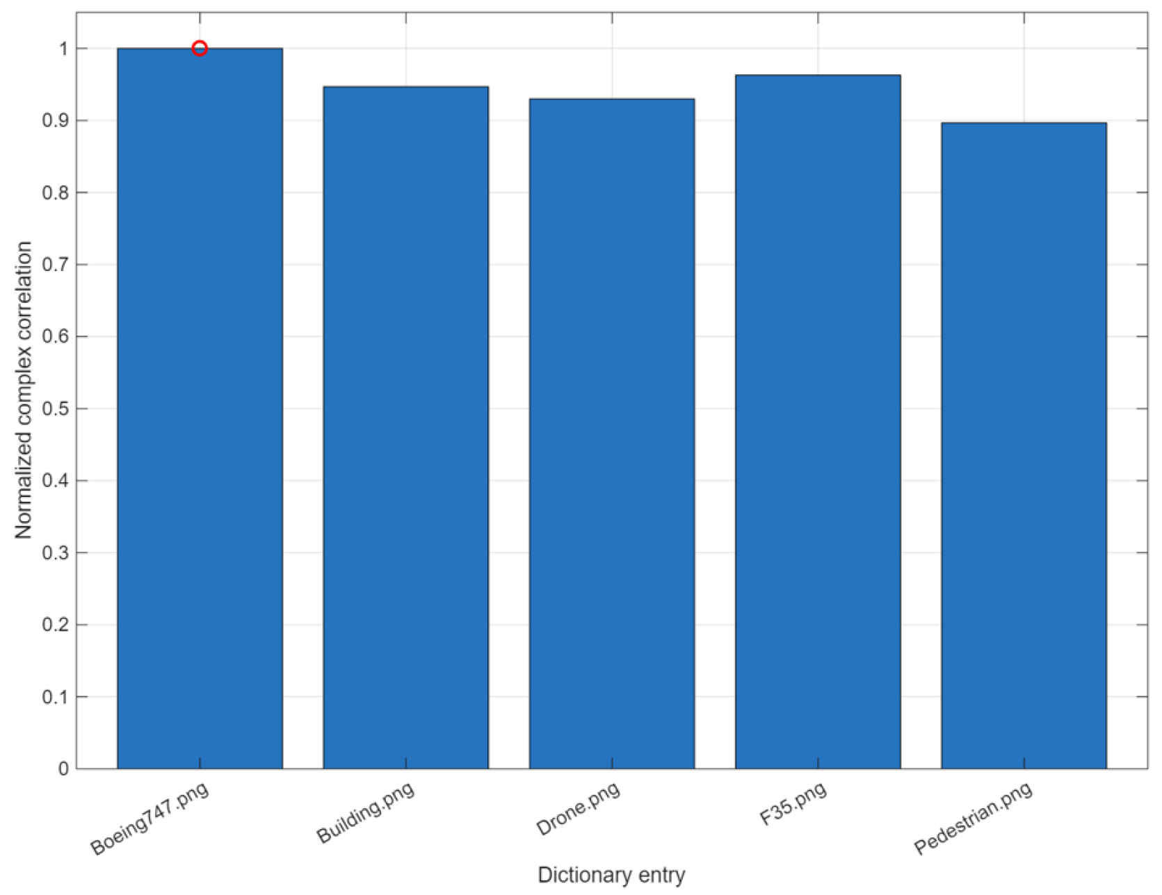
The waveform-domain correlation between SUCA representations is shown in Figure 9. Each bar represents the normalized complex correlation between the reference waveform (Boeing 747) and every other waveform representation. Although the composite waveforms exhibit higher mutual correlation than the original contour images shown in Figure 8, the deterministic waveform representations remain sufficiently separated owing to the phase diversity introduced by the SUCA geometry. This analysis demonstrates that different object hypotheses generate distinguishable waveform representations and therefore can be reliably recognized directly in waveform space without intermediate image reconstruction.
Figure 9.
Waveform-domain correlation between SUCA dictionary entries for contour targets. Each bar shows the normalized complex correlation between the Boeing 747 reference waveform and the remaining dictionary waveforms. The Boeing 747 image is selected as the reference and is indicated by a red circle.
5. Validation of the Waveform Representation Framework
The separability analysis presented in the previous section is now validated quantitatively using four complementary performance metrics. Together, these metrics evaluate the recognition capability of the proposed waveform representation framework, the corresponding physical power balance, and the resulting recognition performance in the presence of noise. The adopted validation methodology follows the classical radar detection framework described in [20]. Specifically, the validation includes:
Additional simulation and statistical parameters used in the numerical evaluation are provided in Appendix A.
- (i)
- probability of recognition versus representation , where the signal-to-noise ratio is defined with respect to the deterministic waveform representation;
- (ii)
- physical power-balance analysis and the corresponding physical signal-to-noise ratio, , derived from the simulated signal and noise powers;
- (iii)
- receiver operating characteristic (ROC) performance.
5.1. Extended-Target Recognition Performance and Representation Comparison
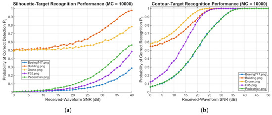
Figure 10 compares the recognition performance obtained using the silhouette and contour target representations. As discussed above, the contour representation provides substantially better waveform-domain separability than the filled silhouette under the equal-weight scattering-center model used in the present study. This difference is clearly reflected in the probability-of-correct-recognition curves.
Figure 10.
Probability of correct recognition versus received-waveform SNR for QR-based normalized-correlation matching: (a) silhouette representation and (b) contour representation.
For the silhouette representation, only the building and drone maintain moderate recognition probability over the investigated SNR range, while the Boeing 747, F–35, and pedestrian remain difficult to distinguish even at relatively high received-waveform SNR. In contrast, the contour representation produces a great and monotonic improvement in recognition probability for all five target classes. The drone, building, and F–35 approach unity probability of correct recognition at sufficiently high SNR, while the Boeing 747 and pedestrian also exhibit substantial improvement.
The comparison confirms that the reduced contour representation retains more discriminative geometric information for the present waveform dictionary than the filled silhouette representation. The contour model is therefore adopted as the principal extended-target representation in the subsequent performance analysis.
The present recognition results are limited to the five representative target categories considered in this simulation study and should therefore be interpreted as a proof-of-principle demonstration rather than as a general validation for arbitrary target classes.
5.2. Power-Balance Analysis
The second validation metric relates the deterministic waveform representation in (12) to the minimum received signal power required for reliable detection. This detection threshold is computed from the receiver noise floor as
where is the receiver bandwidth, is the receiver noise figure, is the required detection signal-to-noise ratio, and is the processing gain.
The analysis assumes a SUCA consisting of ring elements with ring radius , operating at with a deterministic dither frequency step , corresponding to a dwell time of Tscan = 1 μs. The illuminator–target range is , the target–receiver range is , , and the receiver bandwidth is .
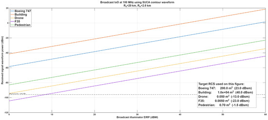
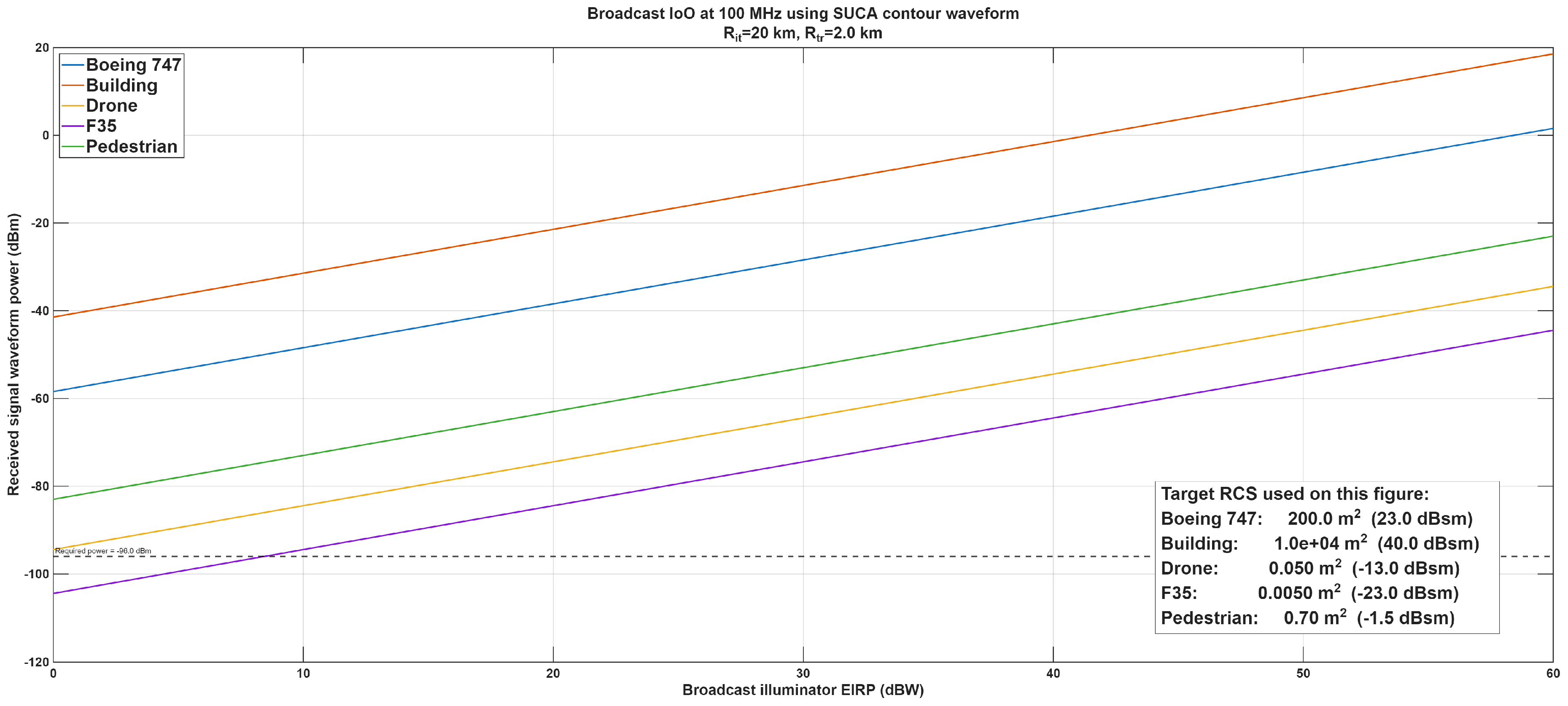
Figure 11 shows the received waveform power as a function of illuminator EIRP for representative target radar cross sections listed in the inset. The horizontal dashed line corresponds to the received-power level required to provide a received-waveform SNR for the assumed receiver bandwidth and noise figure. The intersection of each target curve with this threshold therefore indicates the illuminator EIRP required to reach this received-SNR operating point.
Figure 11.
Received signal waveform power versus illuminator EIRP for representative target radar cross-sections. The dashed line corresponds to the received power required for a received-waveform SNR.
Large targets such as the building and Boeing 747 exceed the required received-power level throughout the EIRP range considered. The pedestrian also remains above the SNR reference over the complete plotted range. The drone reaches the required level at an illuminator EIRP of approximately , while the smaller F–35 radar cross-section requires approximately .
The power-balance result should be interpreted together with the extended-target recognition results of Figure 10. The value was selected as a representative high-SNR operating point at which the contour-based recognition probability is already high for most of the investigated target classes. Because waveform separability is target-dependent, the exact SNR required to obtain a specified probability of correct recognition is not identical for all targets.
These results indicate that the received-power levels associated with the corrected contour-waveform model are compatible with practical illumination levels for the representative geometry and radar cross sections considered here. They are intended only as an illustrative feasibility analysis and are based on representative target RCS values together with idealized propagation and scattering assumptions. Consequently, the calculated EIRP values and corresponding received-power levels should not be interpreted as definitive operational detection ranges. Actual performance will depend on target aspect, propagation loss, multipath, environmental conditions, and the specific illuminator geometry.
5.3. Receiver Operating Characteristic (ROC)
The receiver operating characteristic (ROC) provides a standard performance measure for binary waveform detection by plotting the probability of detection versus the probability of false alarm as the detection threshold is varied.
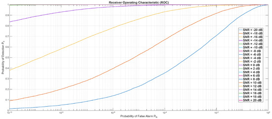
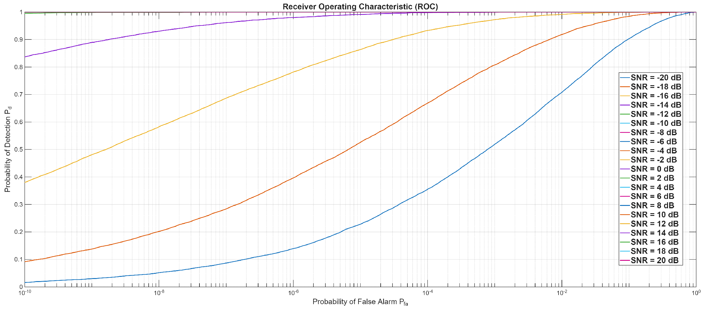
Figure 12 shows the ROC curves obtained for the Boeing 747 contour waveform at several received-waveform SNR levels. The ROC experiment is distinct from the five-class recognition study described above. Here, the detector tests whether a known waveform is present in additive noise, whereas the recognition experiment requires selection of the correct target waveform from among all five dictionary entries.
Figure 12.
Receiver operating characteristic (ROC) curves showing probability of detection versus false-alarm probability for several received-waveform SNR levels.
For the ROC analysis, the noise-only hypothesis was generated using independent realizations of circular complex Gaussian noise. For each realization, the normalized-correlation detection statistic was computed using the known Boeing 747 contour waveform. The resulting samples were used to estimate the mean and standard deviation of the noise-only statistic. For a prescribed false-alarm probability , the detection threshold was determined from the Gaussian-tail approximation as
where is the inverse standard-normal cumulative distribution function. For each received-waveform SNR, independent trials were generated by adding complex Gaussian noise to the deterministic target waveform. The probability of detection was estimated as the fraction of trials for which the detection statistic exceeded . Thus, specifies the noise-only threshold through the fitted distribution, while is estimated directly by Monte Carlo simulation.
As expected, increasing received-waveform SNR shifts the ROC curves toward the upper-left region of the diagram, corresponding to higher detection probability at a given false-alarm probability. At the SNR levels associated with reliable target recognition, the binary waveform-detection problem is already substantially easier. Thus, the recognition performance reported above is governed primarily by the separability of the competing target waveform representations rather than by the ability to distinguish a known waveform from noise.
The ROC results should therefore not be interpreted as an additional processing gain introduced by the QR transformation. As discussed previously, the QR representation preserves the normalized-correlation decision rule; it does not itself increase detection SNR. Its role is to provide an orthogonal representation of the physical waveform dictionary for efficient and numerically convenient comparison.
The difference between the ROC and multi-class recognition results is also consistent with their different decision problems. Binary detection compares one known target waveform against the noise-only hypothesis, whereas target recognition requires discrimination among several structured waveform hypotheses that may exhibit substantial mutual correlation. Consequently, correct target recognition generally requires a higher received-waveform SNR than binary detection of a known waveform.
5.4. Detection Performance Versus Illuminator EIRP
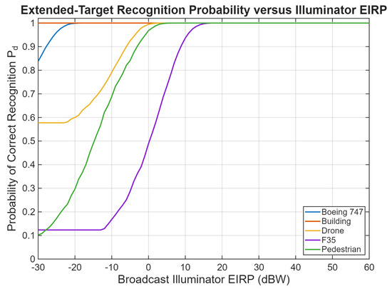
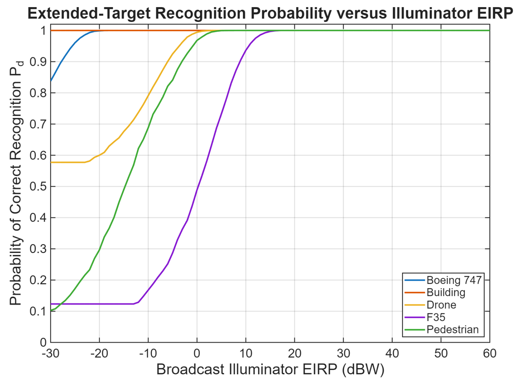
To evaluate the practical sensitivity of the proposed framework, the probability of detection shown in Figure 13 was computed as a function of the illuminator EIRP for several representative targets. The results illustrate the illumination levels required to achieve reliable detection for targets with different radar cross-sections.
Figure 13.
Detection probability as a function of broadcast illuminator effective isotropic radiated power (EIRP) for several representative targets.
For large radar cross-section objects such as commercial aircraft (), reliable detection is achievable with relatively low illumination power. In the assumed geometry (target–receiver range ), the simulation indicates that detection of a Boeing 747-sized target becomes possible even for illuminator powers below .
For targets with smaller radar cross-sections, the required illumination power increases accordingly. For example, a low-RCS aircraft such as an F–35 () requires illumination levels on the order of 10–. Moderate-size targets such as pedestrians () can still be detected at illumination levels of approximately 5–, while small aerial vehicles such as drones () fall between these regimes.
These results indicate that, in addition to high-power broadcast transmitters, moderate-power local transmitters may also serve as practical illuminators for short-range sensing applications such as traffic monitoring, navigation assistance, and airspace awareness.
The comparison with conventional matched-filter detection should be interpreted with care because the proposed receiver processes a structured waveform formed from multiple spatial channels and temporal samples. The present simulations use SUCA ring channels and complex temporal samples over a 1 μs dwell. These samples contribute coherently to the resulting deterministic waveform representation. Accordingly, the ROC results are not interpreted here as demonstrating an intrinsic SNR gain relative to a classical single-pulse matched-filter detector. A single equivalent processing-gain value has not been derived for the present waveform-domain formulation and is therefore not assigned. The demonstrated performance is instead attributed to coherent processing of the structured waveform samples and to the separability of the corresponding physical dictionary hypotheses.
6. Conclusions
This paper introduced a physics-based waveform representation framework for passive target recognition based on the RaDICAL sensing architecture. Rather than learning object representations from large labeled datasets, the proposed approach generates deterministic waveform representations directly from electromagnetic wave propagation using a Sparse Uniform Circular Array (SUCA) with deterministic dither. Recognition is then performed by matching the measured waveform representation against a physics-based dictionary of predicted object hypotheses using QR-domain correlation processing.
A key contribution of this work is the extension of the previously developed RaDICAL point-target localization framework to recognition of extended objects. The proposed representation-learning approach demonstrates that object geometry can be encoded directly into the received waveform without reconstructing conventional radar images or requiring a reference channel. In addition, the contour-based object representation introduced in this work substantially reduces waveform redundancy, dictionary size, computational complexity, and memory requirements while preserving the dominant geometric features responsible for reliable recognition.
The proposed framework was validated using multiple complementary performance metrics, including waveform representation separability, probability of detection versus dictionary SNR, physical power-balance analysis, probability of detection versus physical SNR, receiver operating characteristic (ROC) performance, and detection probability versus illuminator EIRP. Together, these results demonstrate that the proposed waveform representations possess strong discriminative capability and enable reliable recognition under realistic passive illumination conditions.
Future work will focus on experimental validation using a prototype RaDICAL receiver system, extension of the representation dictionary to more realistic three-dimensional target models with measured scattering characteristics, and adaptive refinement of waveform representations for diverse operational environments.
Overall, the results indicate that deterministic physics-based waveform representations provide a viable alternative to conventional data-driven, physics-based waveform representation for passive radar sensing. The proposed framework shifts the emphasis from image reconstruction and statistical feature extraction toward direct recognition in waveform space, opening new opportunities for passive sensing systems based on structured electromagnetic representations.
Funding
This research received no external funding.
Data Availability Statement
The data presented in this study were generated by numerical simulations using the mathematical model and parameters described in the manuscript. The numerical data supporting the results are available from the corresponding author upon request. The data are not deposited in a public repository because they consist of simulation outputs generated specifically for this study.
Conflicts of Interest
The author declares no conflicts of interest.
Appendix A. Simulation and Statistical Parameters
Table A1.
Simulation and statistical parameters used in the numerical evaluation.
References
- Volman, V.; Nessel, J.A. Waveform-Domain Passive Sensing Using a Sparse Uniform Circular Array with Deterministic Multifrequency Dither. Sensors 2026, 26, 3816. [Google Scholar] [PubMed]
- Volman, V. Nonlinear SUCA Waveforms and QR-Domain Maximum-Likelihood Detection for Passive RaDICAL Monostatic Radar. TechRxiv 2025. [Google Scholar] [CrossRef] [Scilit] [PubMed]
- Griffiths, H.D.; Baker, C.J. An Introduction to Passive Radar; Artech House: Boston, MA, USA; London, UK, 2017. [Google Scholar]
- Griffiths, H.D.; Baker, C.J.; Papatsoris, S. Passive coherent location radar systems. IEE Proc. Radar Sonar Navig. 2003, 152, 153–159. [Google Scholar]
- Howland, P.E.; Maksimiuk, D. FM radio based bistatic radar. IEE Proc. Radar Sonar Navig. 2005, 152, 107–115. [Google Scholar] [CrossRef] [Scilit]
- Colone, F.; Woodbridge, K.; Maresca, P. Aircraft detection using FM radio-based passive radar. IEEE Trans. Aerosp. Electron. Syst. 2010, 46, 689–705. [Google Scholar]
- Kulpa, K.; Malanowski, M.; Samczyński, P. Passive Radar: From Detection to Imaging. In Proceedings of the IEEE Radar Conference (RadarConf’19), Boston, MA, USA, 22–26 April 2019. [Google Scholar]
- Wacks, S.; Yazıcı, B. Passive synthetic aperture hitchhiker imaging of ground moving targets—Part 1: Image formation and velocity estimation. IEEE Trans. Image Process. 2014, 23, 2487–2500. [Google Scholar] [CrossRef] [Scilit] [PubMed]
- Wacks, S.; Yazıcı, B. Passive synthetic aperture hitchhiker imaging of ground moving targets—Part 2: Performance analysis. IEEE Trans. Image Process. 2014, 23, 4126–4138. [Google Scholar] [CrossRef] [Scilit] [PubMed]
- Li, J.; Stoica, P. MIMO Radar with Colocated Antennas. IEEE Signal Process. Mag. 2007, 24, 106–114. [Google Scholar] [CrossRef] [Scilit]
- Haimovich, A.M.; Blum, R.S.; Cimini, L.J. MIMO Radar with Widely Separated Antennas. IEEE Signal Process. Mag. 2008, 25, 116–129. [Google Scholar] [CrossRef] [Scilit]
- Lanterman, A.D. Passive radar imaging and target recognition using illuminators of opportunity. In Proceedings of the RTO SET Symposium on Target Identification and Recognition Using RF Systems, Oslo, Norway, 11–13 October 2004; Available online: https://publications.sto.nato.int/publications/STO$120Meeting$120Proceedings/RTO-MP-SET-080/MP-SET-080-24.pdf (accessed on 20 September 2026).
- Meller, M. Efficient Signal Processing Algorithms for Passive Radars. In Proceedings of the NATO Science and Technology Organization Meeting Proceedings STO-MP-SET-187, Brussels, Belgium, 12–14 October 2020; pp. 12-1–12-14. Available online: https://publications.sto.nato.int/publications/STO$120Meeting$120Proceedings/STO-MP-SET-187/MP-SET-187-12.pdf (accessed on 20 September 2026).
- Tang, Z.; Ma, H.; Qu, Y.; Mao, X. UAV Detection with Passive Radar: Algorithms, Applications, and Challenges. Drones 2025, 9, 76. [Google Scholar] [CrossRef] [Scilit]
- Brennan, P.; Chetty, K.; Li, W.; Vishwakarma, S.; Colone, F.; Amiri, A. Reference-Free Passive RF Imaging Using Near-Field Spatial Processing. In Proceedings of the 2024 International Conference on Computing, Internet of Things and Microwave Systems (ICCIMS), Gatineau, QC, Canada, 29–31 July 2024. [Google Scholar] [CrossRef] [Scilit]
- Di Seglio, M.; Filippini, F.; Bongioanni, C.; Colone, F. Comparing reference-free WiFi radar sensing approaches for monitoring people and drones. IET Radar Sonar Navig. 2024, 18, 107–124. [Google Scholar] [CrossRef] [Scilit]
- Bengio, Y.; Courville, A.; Vincent, P. Representation Learning: A Review and New Perspectives. IEEE Trans. Pattern Anal. Mach. Intell. 2013, 35, 1798–1828. [Google Scholar] [CrossRef] [Scilit] [PubMed]
- Elad, M. Sparse and Redundant Representations: From Theory to Applications in Signal and Image Processing; Springer: New York, NY, USA, 2010. [Google Scholar]
- Karniadakis, G.E.; Kevrekidis, I.G.; Lu, L.; Perdikaris, P.; Wang, S.; Yang, L. Physics-Informed Machine Learning. Nat. Rev. Phys. 2021, 3, 422–440. [Google Scholar] [CrossRef] [Scilit]
- Richards, M.A. Fundamentals of Radar Signal Processing, 2nd ed.; McGraw-Hill: New York, NY, USA, 2014. [Google Scholar]


Disclaimer/Publisher’s Note: The statements, opinions and data contained in all publications are solely those of the individual author(s) and contributor(s) and not of MDPI and/or the editor(s). MDPI and/or the editor(s) disclaim responsibility for any injury to people or property resulting from any ideas, methods, instructions or products referred to in the content. |
© 2026 by the author. Licensee MDPI, Basel, Switzerland. This article is an open access article distributed under the terms and conditions of the Creative Commons Attribution (CC BY) license.