


Abstract
Traditional liquid-resistive mounts are widely used in vehicle powertrain vibration isolation because of their favorable low-frequency damping characteristics. However, they usually suffer from pronounced high-frequency dynamic stiffening, which significantly degrades their vibration-isolation performance in the high-frequency range and remains a critical limitation in passive mount design. To address this problem, this study presents the systematic modeling, comparative analysis, and structural optimization of liquid-resistive mounts with different internal configurations. Three representative mount structures, namely the decoupler-membrane type, the conventional bell-plate type, and a novel bell-plate configuration, are first described in terms of their structural characteristics and working mechanisms. Based on the lumped-parameter method, mathematical models of the three mounts are established, and their low- and high-frequency dynamic characteristics are comparatively investigated. The vibration isolation performance of the mounts is further evaluated under various excitation conditions to clarify the influence of structural modifications on the dynamic response and transmitted force. In addition, sensitivity analysis is performed using the ISIGHT software platform (ISIGHT 5.6 Design Gateway) to identify the key parameters governing high-frequency performance. Subsequently, structural optimization is conducted using nonlinear programming under the quadratic Lagrangian algorithm and the Six Sigma method. The results indicate that the introduction of a bell plate has little influence on the low-frequency dynamic characteristics, while it effectively suppresses high-frequency hardening and improves high-frequency vibration isolation. Moreover, the Six Sigma optimization method achieves better performance improvement than the NLPQL approach, providing a useful reference for the design and optimization of passive liquid-resistive mounts.
MSC:
34A30; 37M05; 65K10; 90C30; 93A30
1. Introduction
The primary functions of engine mounts include the following: (1) supporting the engine by bearing its weight and ensuring that it is securely connected to the vehicle chassis or frame; and (2) providing vibration isolation. During engine operation, vibrations inevitably occur, and the engine mount reduces their transmission to the vehicle body, thereby decreasing interior noise and improving ride comfort. In addition, engine mounts can attenuate impacts transmitted to the engine under uneven road conditions, acceleration, deceleration, and cornering, thus protecting the engine and related components from damage [1,2,3]. The ideal performance requirements of engine mounting systems can be summarized as follows [4,5,6]. First, under low-frequency large-amplitude excitation in the range of 1–50 Hz, the engine mount should exhibit high stiffness and high damping to suppress low-frequency vibrations induced by road excitation and to prevent excessive powertrain displacement during vehicle acceleration, braking, and other transient operating conditions, which may otherwise lead to collision with the vehicle body. Second, under high-frequency, small-amplitude excitation, the mount should exhibit low stiffness and low damping to reduce the transmission of powertrain vibrations to the vehicle body. Third, during engine idling, the mount should exhibit low stiffness to attenuate idle-speed jitter. With increasingly stringent requirements for vehicle vibration and noise control, engine mounts have gradually evolved from conventional rubber mounts to liquid-resistive, semi-active, and active mounts [7]. Among these, rubber mounts and liquid-resistive mounts have been widely used in the automotive industry owing to their simple structures and low cost. However, once their structures are designed and molded, the performance characteristics of rubber and liquid-resistive mounts are difficult to modify, making it challenging for them to simultaneously meet vibration-isolation requirements across different excitation conditions.
To overcome the limitations of conventional rubber mounts, researchers have developed liquid mounts. Liquid-resistive mounts exhibit high stiffness and high damping at low frequencies, thereby improving low-frequency vibration isolation performance. Previous studies have investigated the effects of the number, size, and length of inertia channels on the low-frequency dynamic characteristics of liquid mounts, as well as the modeling of liquid bushings with different combinations of inertia channels and orifice flow paths [8,9,10]. Christopherson [11] examined the applicability of nonlinear finite element methods to the challenging task of identifying behavioral parameters in passive liquid engine mount structures. By employing hyperelastic constitutive models, the incompressible behavior of the rubber material forming the mount body was accurately captured, and the resulting analysis data were incorporated into a previously developed lumped-parameter model to comprehensively characterize the dynamic behavior of two different liquid engine mounts. Ghosh [12] investigated the sources of rattling noise in liquid mounts and identified three main factors: resonance noise from the rubber main spring and support arm, cavity noise, and impact noise from the decoupler membrane. Recommendations were provided to avoid rattling during the design of liquid mounts; however, specific solutions to eliminate these noise sources were not proposed. Verma [13] conducted full-vehicle noise tests on a vehicle with rattling issues and determined that the rattling originated from the decoupler membrane impacting the liquid mounts. The impact-induced rattling was found to be broadband noise in the 300–600 Hz range. Adding a rubber liner to the decoupler membrane reduced impact noise by 6 dB. Singh [14] proposed a prototype-level testing method for evaluating rattling in liquid mounts. The validity of the sample-level test method was verified by comparing the cavity noise and decoupler membrane impact noise of four liquid mount samples, with both vehicle-level and sample-level test results. Wang [15] developed a finite element analysis method for predicting rattling in liquid mounts. This method indirectly evaluated the risk of rattling by simulating the contact stiffness between the decoupler membrane and the spacer plate, and its effectiveness was confirmed through sample-level rattling tests of liquid mounts.
Tiwari and Adiguna [16,17] established mathematical relationships among the upper liquid chamber pressure, volumetric flexibility, and volumetric stiffness under two conditions: with and without consideration of the vacuum effect in the upper liquid chamber. In addition, a computational model of the volumetric flexibility of the upper liquid chamber, accounting for the vacuum effect, was developed. Shuanguan [18] applied a liquid–solid coupled finite element analysis method to the lumped-parameter identification of liquid mounts. By comparing the parameter identification results obtained from finite element analysis with experimental measurements, it was demonstrated that the liquid–solid coupled finite element simulation method is feasible for predicting key physical parameters in the lumped-parameter model of liquid mounts. Fan [19] conducted extensive experimental studies on inertia-channel liquid mounts and found that both the storage dynamic stiffness curve and the loss angle curve of such mounts pass through an invariant point under different excitation amplitudes. The coordinates of this invariant point vary with the length of the inertia channel. Based on this phenomenon, a method was proposed for identifying the parameters of the invariant point, namely the volumetric stiffness of the upper fluid chamber and the equivalent piston area.
The existing studies can be broadly classified into three categories. Reduced-order and lumped-parameter models mainly describe inertia-channel flow, orifice flow, and chamber compliance and are computationally efficient for repeated parameter analyses [8,9,10,16,17]. Finite-element and fluid–structure-interaction models provide more detailed descriptions of local rubber and fluid deformation but require substantially higher computational costs [11,18]. Experimental and hybrid studies mainly focus on rattling noise, decoupler impact, cavity noise, model validation, and parameter identification [12,13,14,15,19]. Since the present study requires numerous repeated model evaluations for sensitivity analysis and structural optimization, a lumped-parameter model is adopted to balance physical interpretability and computational efficiency.
In summary, liquid-resistive mounts have evolved from first-generation inertia-channel mounts to decoupler-membrane liquid-resistive mounts and further to third-generation bell-plate liquid-resistive mounts. Although their vibration isolation performance has been improved in the low-frequency range, severe dynamic stiffening still occurs at high frequencies. However, existing reduced-order models mainly focus on conventional or single-stage bell-plate configurations and do not clearly describe how successive bell-plate stages redistribute pressure and fluid flow under high-frequency excitation. To address this research gap, the proposed 3_M mount adopts two cascaded bell plates, whereas the 2_M mount contains only one. The additional stage introduces a second intermediate pressure node and an additional hydraulic branch, enabling the high-frequency pressure drop and fluid flow to be redistributed, thereby reducing dynamic stiffening and transmitted force. Therefore, the novelty of the 3_M mount lies in its two-stage pressure–flow configuration rather than simply adding another bell plate. Based on this configuration, this study first compares the dynamic characteristics of three types of liquid-resistive mounts and analyzes the effects of the number of bell plates on their low- and high-frequency dynamic stiffness and loss angle. Second, from a vibration-isolation perspective, the influence of the bell-plate structure and the number of bell plates on the vibration-isolation performance of liquid-resistive mounts is investigated. Finally, ISIGHT is employed to conduct a sensitivity analysis of the novel bell-plate liquid-resistive mount to identify the structural parameters that most significantly influence mount performance. Subsequently, the NLPQL algorithm and the Six Sigma method are adopted for structural optimization and design analysis. The results show that (1) the bell-plate structure and its number have little influence on the low-frequency dynamic characteristics of conventional liquid-resistive mounts; (2) increasing the number of bell plates within the allowable structural space can effectively alleviate the high-frequency hardening problem of conventional liquid-resistive mounts, thereby improving their high-frequency vibration isolation performance; and (3) the Six Sigma optimization algorithm can be used to obtain an improved liquid-resistive mount structure, which further enhances the vibration isolation performance of the mount.
2. Liquid Resistance Mount Characterization
2.1. Structural Analysis
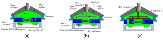
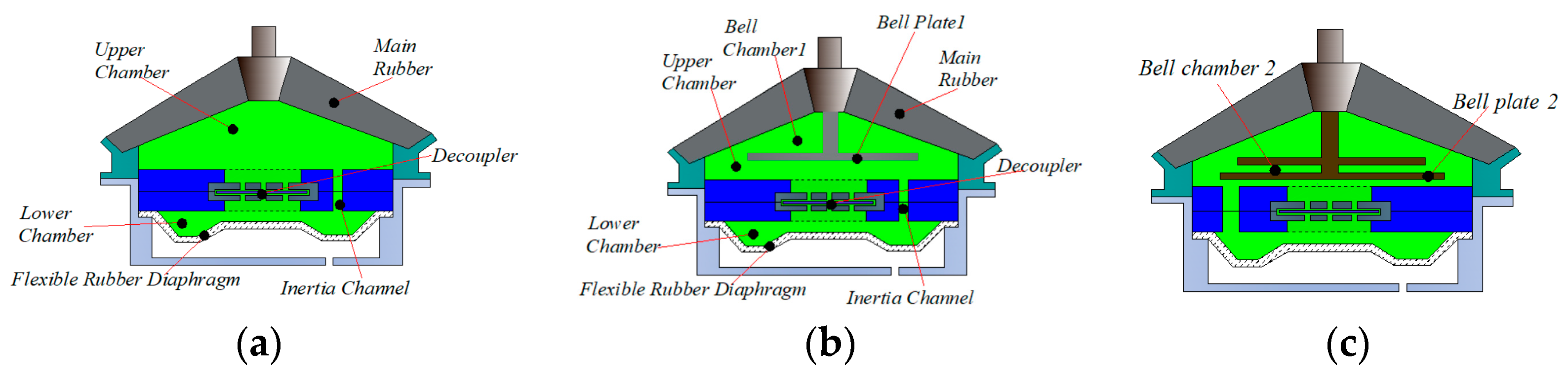
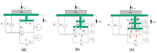
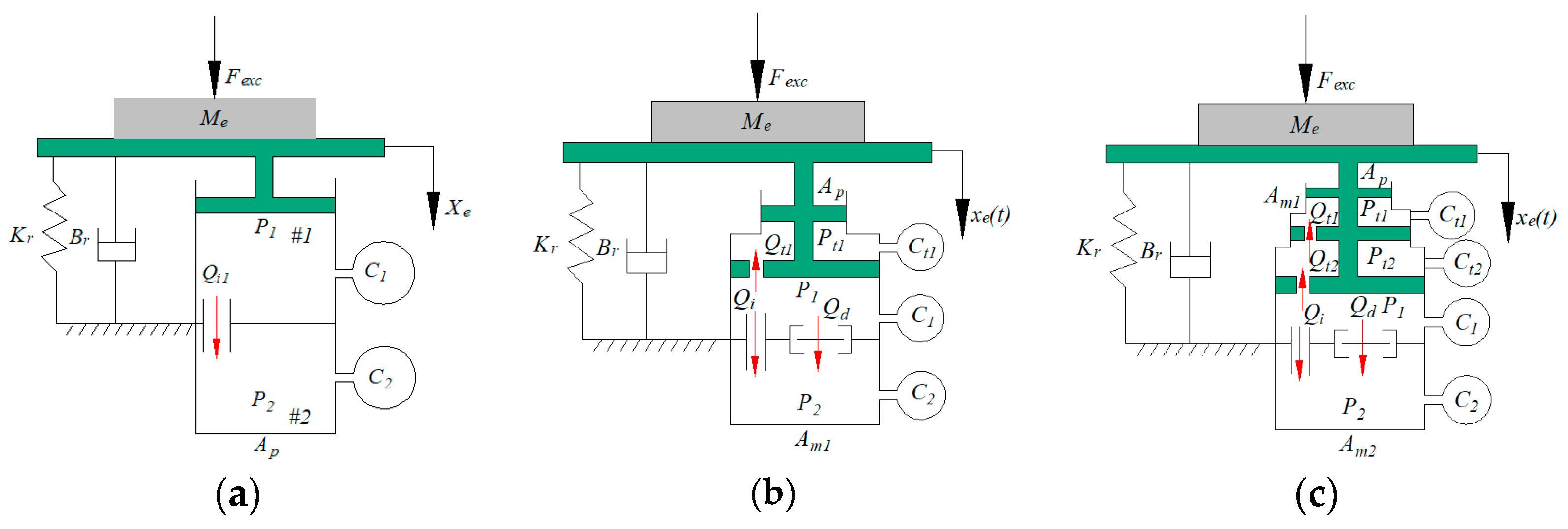
Compared with conventional rubber mounts, liquid mounts provide improved vibration isolation performance over both low- and high-frequency ranges. Figure 1 illustrates three typical configurations of liquid-resistive mounts. Specifically, Figure 1a shows the decoupler-membrane liquid-resistive mount, referred to as the first-generation liquid-resistive mount and denoted as 1_M. Figure 1b presents the bell-plate liquid-resistive mount, referred to as the second-generation liquid-resistive mount and denoted as 2_M. Figure 1c shows the novel bell-plate liquid-resistive mount, referred to as the third-generation liquid-resistive mount and denoted as 3_M. The 1_M liquid-resistive mount mainly consists of a rubber main spring, liquid chambers, a decoupler membrane, an inertia channel, and an outer shell. The rubber main spring is a key load-bearing and connecting component. It serves as an elastic link that supports the powertrain’s weight and transmits forces between the powertrain and the vehicle body. Owing to its inherent elasticity, the rubber main spring also provides a certain degree of preliminary isolation against high-frequency, small-amplitude vibrations. The liquid chambers inside the mount are filled with a special working fluid and are generally divided into an upper chamber and a lower chamber. The flow of fluid between these two chambers plays a critical role in determining the mount’s dynamic characteristics. The decoupler membrane is located between the upper and lower liquid chambers and serves as the core component of the decoupler-membrane liquid-resistive mount. Under low-frequency excitation, the decoupler membrane opens, allowing the upper and lower chambers to communicate. In this case, the fluid flows through a relatively large passage, generating a large damping force and effectively attenuating low-frequency vibrations. Under high-frequency excitation, the decoupler membrane closes, and the fluid mainly flows through small throttling orifices. As a result, the dynamic stiffness of the liquid-resistive mount increases, which contributes to vibration isolation in the high-frequency range. Therefore, the decoupler-membrane liquid-resistive mount can provide vibration isolation effects under both low- and high-frequency excitation conditions.
Figure 1.
Liquid resistance mount structure: (a) 1_M, (b) 2_M, and (c) 3_M.
In addition, the outer shell of the liquid-resistive mount protects the internal structure, maintains the mount’s stability and sealing performance, prevents fluid leakage, and ensures reliable operation. The 2_M mount is developed by adding a bell-plate structure to the upper chamber of the 1_M mount. In the 1_M mount, the fluid motion is governed by the original inertia-channel and decoupler paths without a bell-plate branch. Bell plate 1 in the 2_M mount introduces an additional compliant pressure–flow branch, represented by and , allowing part of the upper-chamber volume fluctuation to be accommodated by bell-plate deformation rather than being transmitted entirely through the original hydraulic paths. In the 3_M mount, bell plate 2 further introduces and , forming a cascaded two-stage path. The two stages share the high-frequency pressure variation and redistribute the oscillatory flow, thereby alleviating dynamic stiffening.
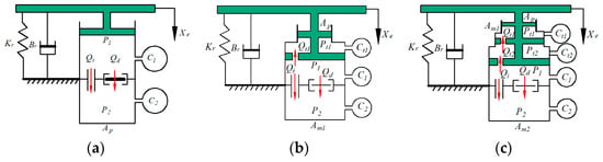
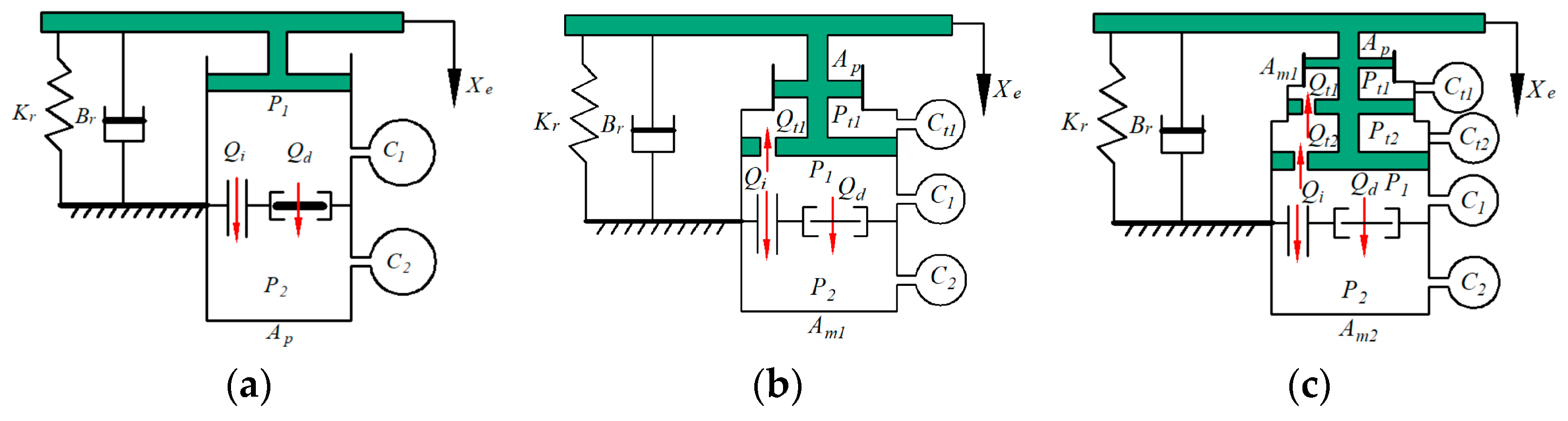
The structural parameters of the three liquid-resistive mounts shown in Figure 2 are defined as follows. The stiffness and damping of the rubber main spring in the upper chamber are denoted by Kr and Br, respectively. P1 and P2 represent the pressures in the upper and lower chambers of the liquid-resistive mount, respectively, while Pt1 and Pt2 denote the pressures associated with bell plate 1 and bell plate 2, respectively. Qi, Qd, Qt1, and Qt2 represent the flow rates through the inertia channel, the decoupler-membrane channel, bell plate 1, and bell plate 2, respectively. C1, C2, Ct1, and Ct2 are the volumetric compliances of the upper chamber, the lower chamber, bell plate 1, and bell plate 2, respectively. In addition, Ap, Am1, and Am2 denote the equivalent cross-sectional areas of the upper chamber, bell plate 1, and bell plate 2, respectively. The detailed values of the structural parameters of the liquid-resistive mounts are listed in the Abbreviations.
Figure 2.
Lumped-parameter models of the liquid-resistive mounts: (a) 1_M, (b) 2_M, and (c) 3_M.
The modeling assumptions are summarized as follows: (1) under the small-amplitude excitation considered in this study, the rubber main spring is represented by the linear stiffness and damping ; (2) the liquid in each flow passage is treated as incompressible, while the deformation of the chambers and bell plates is represented by lumped volumetric compliances; (3) the pressure within each lumped chamber is assumed to be spatially uniform, and the flow through each passage is treated as one-dimensional; (4) viscous losses are represented by linearized hydraulic resistances, while the nonlinear inertia-channel term retained in the governing equations accounts for amplitude-dependent flow behavior; and (5) leakage, cavitation, aeration, temperature dependence, shell flexibility, and parameter variations with operating conditions are neglected.
2.2. Governing Equations
Based on the structural analysis of the 1_M, 2_M, and 3_M liquid-resistive mounts in Section 2.1, the governing equations are presented below. The equations are grouped by mount configuration, and all pressure and flow variables are defined in Figure 2 and the Abbreviations.
(1) 1_M math equation:
(2) 2_M math equation:
(3) 3_M math equation:
According to ref. [20], the frequency-response characteristics of a liquid-resistive mount are characterized by the complex transfer stiffness , its modulus (N/mm), and the loss angle (deg). Here, denotes the prescribed harmonic displacement applied at the excitation end of the mount, and is its corresponding complex amplitude in the frequency domain. denotes the complex amplitude of the force transmitted through the mount. These quantities are defined in Equations (17)–(19). In this study, the term “dynamic stiffness” specifically refers to the modulus of the complex transfer stiffness, while the loss angle represents its phase. Therefore, all dynamic-stiffness curves and peak dynamic-stiffness values reported herein refer to the modulus of the complex transfer stiffness rather than its real part. The subsequent optimization is performed by reducing the peak dynamic stiffness in the 0–200 Hz frequency range.
2.3. Dynamic Characterization
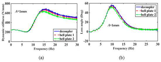
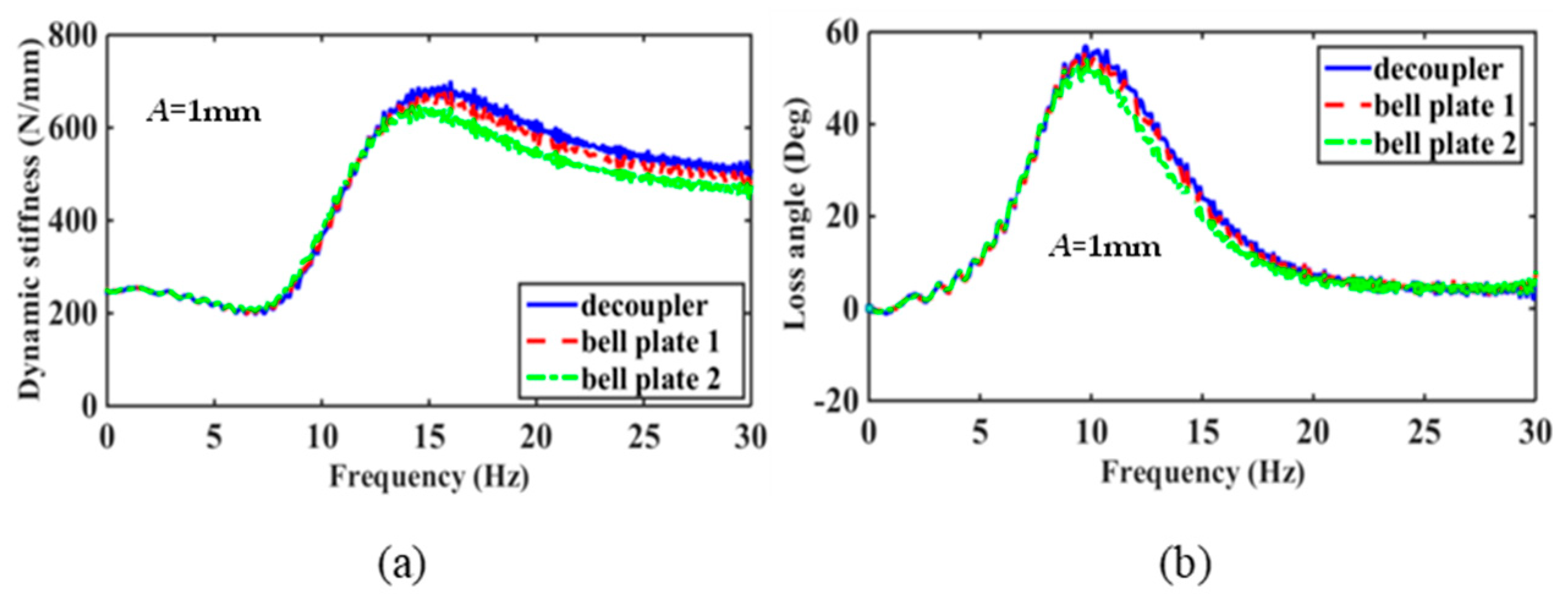
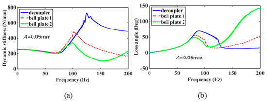
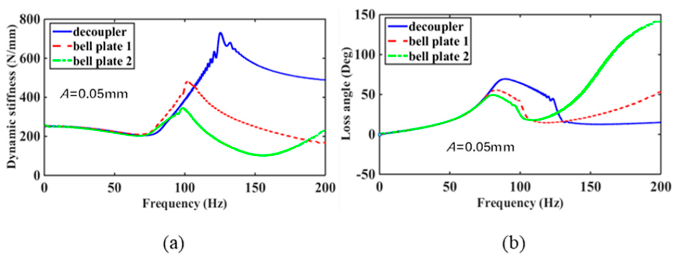
Using Equations (1)–(19) and the parameter values listed in the Abbreviations, the dynamic-stiffness and loss-angle curves of the 1_M, 2_M, and 3_M mounts are obtained, as shown in Figure 3 and Figure 4. Reference [21] is cited only as prior validation of the established hydraulic modeling framework. The present contribution presents the two-stage pressure–flow topology of the 3_M mount, including additional variables, along with a unified comparative analysis and optimization of the three configurations. Because direct prototype validation of 3_M is not included, these results are model-based predictions requiring future experimental verification.
Figure 3.
Dynamic characteristics of liquid resistance mount: (a) dynamic stiffness variation; (b) loss angle variation.
Figure 4.
Dynamic characteristics of liquid resistance mount: (a) dynamic stiffness variation; (b) loss angle variation.
As shown in Figure 3, the peak dynamic stiffness values of the 1_M, 2_M, and 3_M liquid-resistive mounts are 684 N/mm, 669 N/mm, and 643 N/mm, respectively. Meanwhile, the resonance frequencies corresponding to the peak values are nearly identical for the three mount configurations. The peak loss angles of the 1_M, 2_M, and 3_M mounts are 56°, 54°, and 51°, respectively. When the number of bell plates increases from zero to one, the peak dynamic stiffness decreases by 2.2%; when the number increases from zero to two, the peak dynamic stiffness decreases by 5.99%. Similarly, the peak loss angle decreases by 3.57% as the number of bell plates increases from zero to one, and by 8.93% as the number increases from zero to two. These results indicate that increasing the number of bell plates in the conventional liquid-resistive mount structure can slightly modify the mount’s low-frequency dynamic characteristics. However, the magnitude of these changes is relatively small. Therefore, it can be inferred that the introduction of the bell-plate structure has no significant influence on the low-frequency dynamic characteristics of the liquid-resistive mount. Figure 4 shows the variations in dynamic stiffness and loss angle of the 1_M, 2_M, and 3_M mounts under an excitation amplitude of (A = 0.05) mm over the frequency range of f = 0–200 Hz.
As shown in Figure 4a, the peak dynamic stiffness values of the 1_M, 2_M, and 3_M liquid-resistive mounts are 728 N/mm, 480.7 N/mm, and 347 N/mm, respectively. The corresponding frequencies at which the peak dynamic stiffness occurs are 125 Hz, 102 Hz, and 98 Hz, respectively. As shown in Figure 4b, the peak loss angles of the 1_M, 2_M, and 3_M mounts are 70.6°, 57°, and 49°, respectively, with corresponding peak frequencies of 89 Hz, 83 Hz, and 80 Hz.
When the number of bell plates increases from 0 to 1, the peak dynamic stiffness decreases by 33.97%; when the number increases from 0 to 2, the peak dynamic stiffness decreases by 52.34%. Similarly, the peak loss angle decreases by 19.26% as the number of bell plates increases from 0 to 1, and by 30.59% as the number increases from 0 to 2. These results demonstrate that increasing the number of bell plates in the conventional liquid-resistive mount structure significantly influences the mount’s high-frequency dynamic characteristics. In particular, the introduction of the bell-plate structure can effectively alleviate the high-frequency hardening problem commonly observed in conventional liquid-resistive mounts.
3. Vibration Isolation Performance
3.1. Frequency-Domain Characterization
To analyze the high-frequency vibration isolation performance of the three liquid-resistive mounts, the engine excitation Fexc is added to the lumped-parameter model shown in Figure 2. Among them, the lumped-parameter models of the 1_M, 2_M, and 3_M liquid-resistive mounts under engine excitation are shown in Figure 5. #1 and #2 refer to the upper and lower chambers of the resistance mount in Figure 5a, respectively.
Figure 5.
Lumped-parameter models of the liquid-resistive mounts under engine excitation: (a) 1_M, (b) 2_M, and (c) 3_M.
The mathematical models of 1_M, 2_M, and 3_M liquid resistance mounts can be obtained based on the three lumped-parameter models of the liquid-resistive mounts shown in Figure 5, as shown in Equations (1)–(22).
where Equation (20) is the mathematical model for the 1_M liquid resistance mount, Equation (21) is the mathematical model for the 2_M liquid resistance mount, and Equation (22) is the mathematical model for the 3_M liquid resistance mount.
In Equations (20)–(22), denotes the external excitation applied to the mount, whereas denotes the reaction force transmitted to the vehicle body. The term represents the viscoelastic restoring force generated by the rubber main spring. Each product of pressure and its corresponding effective area represents the hydraulic force acting on the load-transmission path. The term represents the dissipative force associated with the decoupler branch, while the terms and represent the reaction forces introduced by bell-plate stages 1 and 2, respectively. Therefore, under the adopted sign convention, the transmitted force is obtained as the algebraic sum of the rubber restoring force, chamber-pressure forces, decoupler-branch dissipative force, and bell-plate reaction forces.
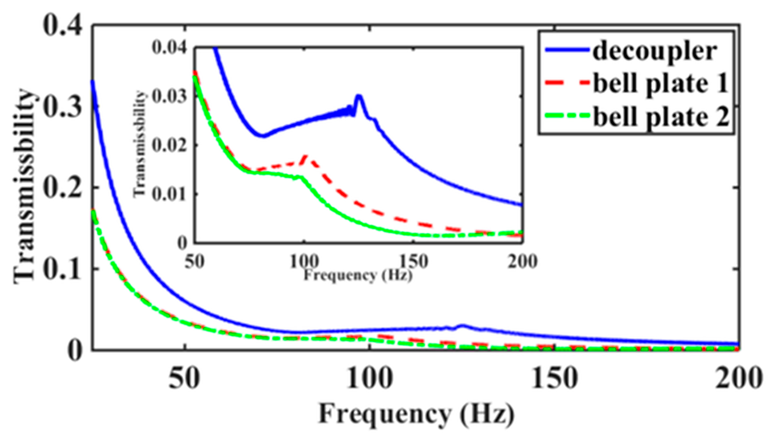
Since this study focuses on the high-frequency vibration isolation performance of liquid-resistive mounts, only the transmissibility characteristics of the three liquid-resistive mounts within the frequency range of (f = 0) − 200 Hz are compared, considering engine excitation and the force transmitted to the vehicle body. Based on Equations (1)–(16) and the parameter values listed in the Abbreviations, the vibration isolation performance of the 1_M, 2_M, and 3_M liquid-resistive mounts under engine excitation can be obtained. Figure 6 shows the high-frequency vibration isolation performance of the three liquid-resistive mounts.
Figure 6.
Frequency domain vibration isolation effect of three structures of liquid resistance mount.
As shown in Figure 6, the high-frequency vibration isolation performance of the 2_M and 3_M liquid-resistive mounts is significantly better than that of the conventional 1_M liquid-resistive mount. This indicates that introducing bell plates can effectively improve the vibration-isolation performance of the mounting system in the high-frequency range. This result is also consistent with the dynamic stiffness characteristics shown in Figure 4, where the peak dynamic stiffness values of the 2_M and 3_M mounts are lower than those of the 1_M mount. Furthermore, Figure 6 shows that the 3_M liquid-resistive mount exhibits better vibration isolation performance than the 2_M mount, further confirming that the peak dynamic stiffness of the 3_M mount is lower than that of the 2_M mount.
3.2. Time-Domain Characterization
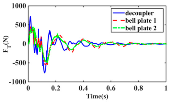
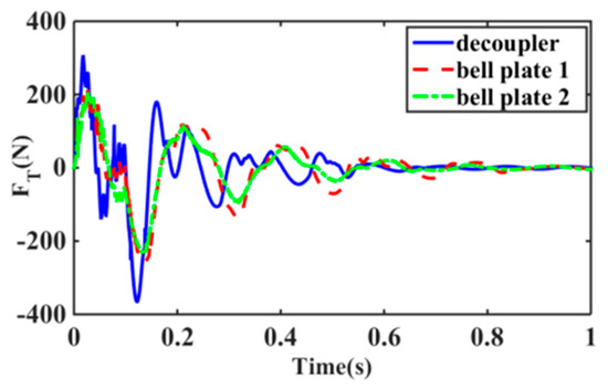
To clarify the vibration isolation ability of the three structures of the liquid resistance mount, the engine excitation is applied as half sinusoidal excitation (i.e., amplitude F = 3000 N, frequency f = 50 Hz) and a step signal, and Matlab software (2024a) is used to obtain the vibration isolation effect of the 1_M, 2_M, and 3_M liquid resistance mounts. The details are shown in Figure 7 and Figure 8.
Figure 7.
Time-domain vibration isolation effect of liquid-resistive mount with half sinusoidal excitation for three structures.
Figure 8.
Time-domain vibration isolation effect of liquid-resistive mount with three structures for step excitation.
As shown in Figure 7, when a half-sine signal with an amplitude of (F = 3000) N and a frequency of (f = 50) Hz is used as the engine excitation, the vibration isolation performance of the 1_M, 2_M, and 3_M liquid-resistive mounts differs significantly. The root mean square (RMS) values of the transmitted force for the 1_M, 2_M, and 3_M mounts are 152.8569 N, 142.071 N, and 128.7996 N, respectively. Compared with the 1_M mount, the transmitted force decreases by 7.1% when the number of bell plates increases from 0 to 1, and by 15.7% when the number increases from 0 to 2. These results indicate that under high-frequency excitation, introducing the bell-plate structure can effectively improve the vibration-isolation performance of liquid-resistive mounts. Moreover, increasing the number of bell plates further enhances vibration isolation.
As shown in Figure 8, when a step signal with an amplitude of 3000 N is used as the engine excitation, the vibration-isolation performance of the 1_M, 2_M, and 3_M liquid-resistive mounts differs significantly. The root mean square (RMS) values of the transmitted force are 77.2121 N for the 1_M liquid-resistive mount, 72.9815 N for the 2_M liquid-resistive mount, and 64.6227 N for the 3_M liquid-resistive mount. Compared with the 1_M mount, the transmitted force decreases by 5.5% when the number of bell plates increases from 0 to 1, and by 16.3% when the number increases from 0 to 2. These results indicate that under high-frequency excitation represented by a 3000 N step input, the bell-plate structure can effectively improve the high-frequency vibration-isolation performance of liquid-resistive mounts. Moreover, increasing the number of bell plates further enhances vibration isolation.
Combining the results shown in Figure 3, Figure 4, Figure 5, Figure 6, Figure 7 and Figure 8, the low-frequency vibration-isolation performance of the 1_M, 2_M, and 3_M liquid-resistive mounts shows only slight differences. In contrast, the 3_M liquid-resistive mount exhibits the best vibration isolation performance in the high-frequency range. Therefore, the subsequent optimization analysis focuses on the 3_M liquid-resistive mount.
4. Structural Optimization of the 3_M Liquid-Resistive Mount
4.1. Sensitivity Analysis
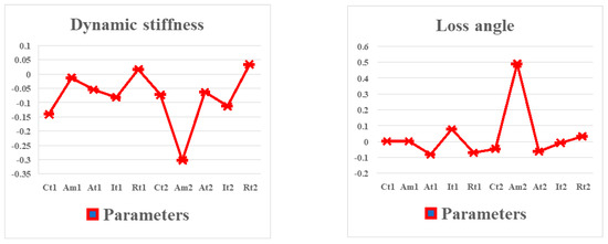
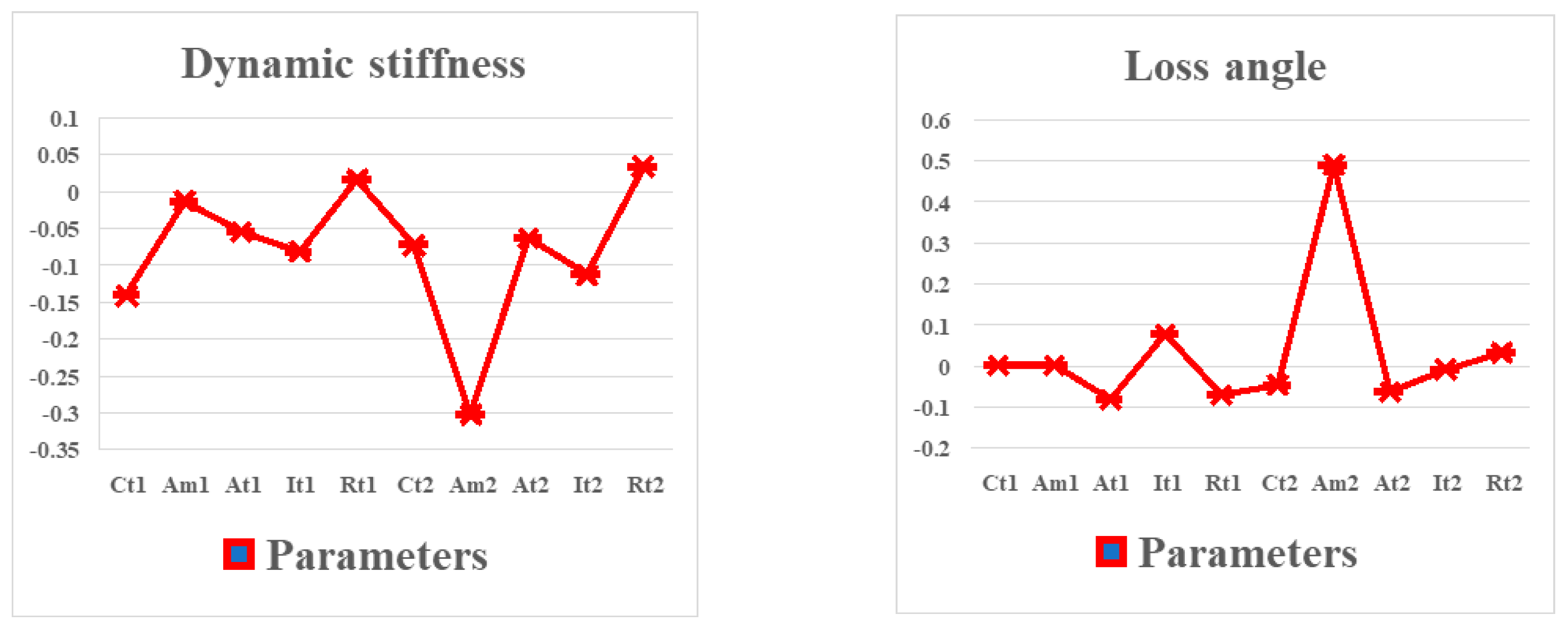
Dynamic stiffness and loss angle were selected as the response quantities. A deterministic one-factor-at-a-time (OAT) parameter sweep was conducted in ISIGHT using uniformly spaced normalized levels. The parameters Ct1, Am1, At1, It1, Rt1, Ct2, Am2, At2, It2, and Rt2 were independently varied over the range of 0.1 to 1.0 times their nominal values. During each sweep, only one parameter was varied, while all remaining parameters were maintained at their nominal values. Accordingly, the analysis is classified as a local OAT sensitivity analysis rather than a global sensitivity analysis. It evaluates the independent effect of each parameter under the nominal settings of the other parameters but does not account for parameter interactions.
As shown in Figure 9, the structural sensitivity analysis of the 3_M liquid-resistive mount indicates that the structural parameters Ct1, Am1, At1, It1, Rt1, Ct2, Am2, At2, It2, and Rt2 affect the dynamic stiffness and loss angle of the mount in different ways. Among these parameters, Am2 and Rt2 have the most significant influence on the dynamic characteristics of the liquid-resistive mount, whereas Am1 and Rt1 have negligible effects. Therefore, in the structural optimization of the 3_M liquid-resistive mount, only the parameters Ct1, At1, It1, Ct2, Am2, At2, It2, and Rt2 need to be considered. In addition, because Am2 and Rt2 exert the greatest influence on the performance of the liquid-resistive mount, larger weighting coefficients can be assigned to these parameters during structural optimization.
Figure 9.
Sensitivity analysis of 3_M liquid resistance mount structure.
4.2. ISIGHT-Based NLPQL and Six Sigma Optimization
To make the optimization procedure explicit, the design vector is defined as x = [Ct1, At1, It1, Ct2, Am2, At2, It2, Rt2]T. The 0–200 Hz interval is the frequency-response evaluation domain, not an optimization constraint. With Kref = 348.7 N/mm, the peak dynamic stiffness of the nominal 3_M mount, the NLPQL problem is formulated as
All variables were scaled before optimization. The first derivatives required by NLPQL were evaluated using the finite-difference procedure in ISIGHT. At the final iteration, stationarity, primal feasibility, and complementary slackness were assessed through the KKT residual, and numerical convergence was determined from
where εKKT, εg, and εJ denote the solver tolerances. For the Six Sigma design, the realized parameters are represented by = x + ξ, where ξ denotes the parameter uncertainty. The robust objective is defined as
where μZ and σZ are the mean and standard deviation of the normalized peak dynamic stiffness, respectively, and β is the prescribed sigma-level coefficient. Accordingly, NLPQL provides a locally converged KKT candidate, whereas the Six Sigma result depends on the uncertainty distributions and sampling settings adopted in ISIGHT. Because the optimization problem is nonlinear and nonconvex, no claim of global optimality is made.
For a consistent comparison, both methods used the nominal 3_M design as the common starting point and were evaluated with the same eight design variables and bounds, lumped-parameter model, excitation condition, 0–200 Hz frequency grid, and peak dynamic-stiffness objective. The NLPQL run was terminated when the ISIGHT convergence checks for the relative objective change, normalized design-variable change, and maximum constraint violation were satisfied, or when the prescribed maximum iteration count was reached. The Six Sigma run used the same nominal design and bounds, while its uncertainty distributions, sigma-level coefficient, sampling scheme, and sampling budget were kept fixed throughout the robust-design calculation. Thus, the reported results compare the two methods under the same physical and numerical model conditions, although their internal stopping mechanisms are method-specific.
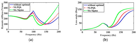
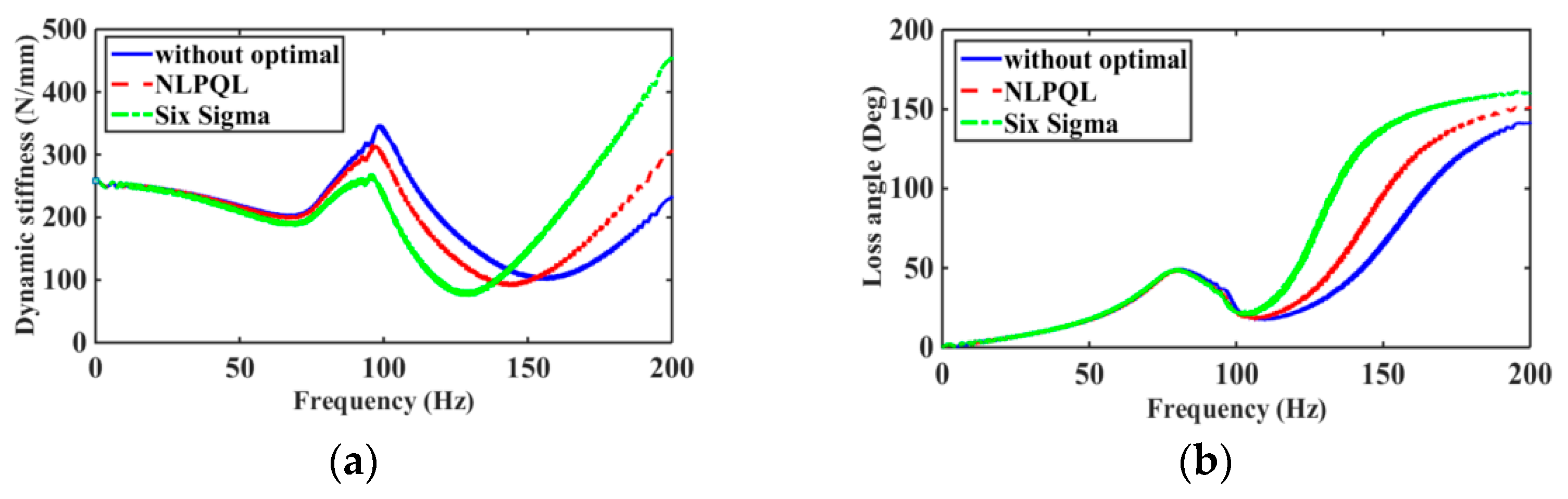
Figure 10 shows the dynamic stiffness and loss angle curves of the 3_M liquid-resistive mount before and after optimization of the structural parameters Ct1, At1, It1, Ct2, Am2, At2, It2, and Rt2 using the NLPQL algorithm and the Six Sigma method in ISIGHT. As shown in Figure 10, the peak frequency and peak dynamic stiffness of the unoptimized 3_M liquid-resistive mount are 98.6 Hz and 348.7 N/mm, respectively. After optimization using the NLPQL algorithm, the peak frequency and peak dynamic stiffness are reduced to 97 Hz and 312.6 N/mm, respectively. After optimization using the Six Sigma method, they are further reduced to 96 Hz and 270.2 N/mm, respectively.
Figure 10.
Dynamic characteristics of 3_M liquid resistance mount: (a) dynamic stiffness; (b) loss angle.
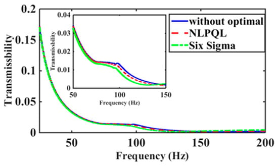
Compared with the unoptimized mount, the nominal peak dynamic stiffness decreases by 10.35% for the locally converged NLPQL design and by 22.51% for the Six Sigma design under the adopted uncertainty settings. The corresponding peak values are 312.6 N/mm and 270.2 N/mm, respectively. Figure 11 also shows lower high-frequency force transmissibility for the Six Sigma design. These results demonstrate better performance in the reported settings; however, they do not constitute proof of global superiority, as NLPQL can converge to a local KKT point, and the Six Sigma result depends on the assumed uncertainty model and sampling accuracy.
Figure 11.
The 3_M liquid resistance mount transmissibility.
4.3. Model Complexity and Limitations
The 1_M, 2_M, and 3_M models contain four, six, and eight first-order dynamic states, respectively. Let n denote the number of states, Nf the number of frequency points, Nt the number of time steps, and Ne the number of repeated model evaluations. When a dense direct solver is used, a complete frequency-domain sweep requires O(Nfn3) computational time and O(n2) working memory. For an implicit time-domain solution, the computational time is approximately O(Ntn3). During sensitivity analysis and optimization, the total frequency-domain cost scales as O(NeNfn3). Because n is no greater than eight in the present models, a single model evaluation is inexpensive, and the main computational overhead arises from repeated evaluations during sensitivity analysis and optimization.
The reduced-order model also has several limitations. It does not resolve local three-dimensional pressure, flow, or deformation fields and neglects leakage, cavitation, aeration, temperature-dependent viscosity, shell flexibility, and nonlinear material behavior beyond the assumed small-amplitude range. The local sensitivity analysis does not account for interactions among global parameters. Moreover, the predicted advantages of the 3_M configuration and the optimized designs require direct prototype validation. NLPQL may converge to a local solution, whereas the Six Sigma results depend on the assumed uncertainty model and sample size.
5. Conclusions
The high-frequency hardening problem inherent in conventional liquid-resistive mounts has long limited their effectiveness in high-frequency vibration isolation. The main contribution of this study is the proposal of a third-generation liquid-resistive mount configuration, denoted as 3_M, followed by a systematic analysis of its low- and high-frequency dynamic characteristics in the frequency domain and its vibration isolation performance in the time domain. First, the structural diagrams and lumped-parameter models of three liquid-resistive mount configurations, namely 1_M, 2_M, and 3_M, are presented, and their corresponding mathematical models are established. Subsequently, based on these models, the differences in low- and high-frequency dynamic characteristics and vibration isolation performance among the three configurations are analyzed. Finally, sensitivity analysis of the structural parameters of the 3_M liquid-resistive mount is carried out using the ISIGHT software platform, followed by structural optimization using the NLPQL algorithm and the Six Sigma method. The results show that the number of bell plates and the structural configuration have no significant influence on the low-frequency dynamic characteristics of the liquid-resistive mount. However, they can effectively mitigate the high-frequency hardening problem. Moreover, increasing the number of bell plates improves the vibration isolation performance compared with the conventional design. In particular, under the adopted design bounds and uncertainty settings, the Six Sigma formulation yields lower nominal peak dynamic stiffness and force transmissibility than the locally converged NLPQL solution; no claim of global optimality is made.
Author Contributions
Writing—review and editing, Methodology, Writing—original draft, Funding acquisition, Y.C.; Software, Formal analysis, Investigation, Methodology, Z.L.; Methodology, Z.G.; Investigation, Methodology, Y.L., Data curation, W.D. All authors have read and agreed to the published version of the manuscript.
Funding
This work was supported in part by the Fujian Provincial Natural Science Foundation of China under Grants 2022J011183 and 2022J011182 and in part by the National Foundation Cultivation Program of Sanming University under Grant PYT2303.
Data Availability Statement
The raw data supporting the conclusions of this article will be made available by the authors on request.
Conflicts of Interest
The authors declare no conflicts of interest.
Abbreviations
The following abbreviations are used in this manuscript:
| Symbol | Name | Value |
| Rubber stiffness | ||
| Rubber damping | ||
| Equivalent cross-sectional area of the upper chamber | ||
| Upper chamber volume flexibility | ||
| Flexibility of the lower chamber volume | ||
| Fluid inertia in decoupler | ||
| Pressure normalized constant | ||
| Flow normalized constant | ||
| Linear fluid resistance in decoupler | ||
| Inertia channel width | ||
| Controlled inertia channel length | ||
| Length of inertia channel in the upper half | ||
| Magnetorheological fluid viscosity | ||
| Magnetorheological fluid density | ||
| Decoupler position control constant | ||
| Decoupler switching function shape control constant | ||
| Coefficient of inertia of the moving fluid of bell plate 1 | ||
| Damping coefficient of the moving fluid of bell plate 1 |
References
- Qatu, M.S.; Abdelhamid, M.K.; Pang, J.; Sheng, G. Overview of automotive noise and vibration. Int. J. Veh. Noise Vib. 2009, 5, 1–35. [Google Scholar] [CrossRef] [Scilit]
- Qatu, M.S. Recent research on vehicle noise and vibration. Int. J. Veh. Noise Vib. 2012, 8, 289–301. [Google Scholar] [CrossRef] [Scilit]
- Hausberg, F.; Scheiblegger, C.; Pfeffer, P.; Plöchl, M.; Hecker, S.; Rupp, M. Experimental and analytical study of secondary path variations in active engine mounts. J. Sound Vib. 2015, 340, 22–38. [Google Scholar] [CrossRef] [Scilit]
- Zhang, Y.Q.; Shangguan, W.B. A novel approach for lower frequency performance design of hydraulic engine mounts. Comput. Struct. 2006, 84, 572–584. [Google Scholar] [CrossRef] [Scilit]
- Barszcz, B.; Dreyer, J.T.; Singh, R. Experimental study of hydraulic engine mounts using multiple inertia tracks and orifices: Narrow and broad band tuning concepts. J. Sound Vib. 2012, 331, 5209–5223. [Google Scholar] [CrossRef] [Scilit]
- Fan, R.; Fei, Z.; Zhou, B.; Gong, H.-B.; Song, P.-J. Two-step dynamics of a semiactive hydraulic engine mount with four-chamber and three-fluid-channel. J. Sound Vib. 2020, 480, 115403. [Google Scholar] [CrossRef] [Scilit]
- Shangguan, W.B. Engine mounts and powertrain mounting systems: A review. Int. J. Veh. Des. 2009, 49, 237–258. [Google Scholar] [CrossRef] [Scilit]
- Lin, Z.; Huang, Y. Effect of bell plate structure on high and low frequency characteristics of hydraulic mount. Appl. Rheol. 2024, 34, 20240014. [Google Scholar] [CrossRef] [Scilit]
- Chai, T.; Dreyer, J.T.; Singh, R. Frequency domain properties of hydraulic bushing with long and short passages: System identification using theory and experiment. Mech. Syst. Signal Process. 2015, 56–57, 92–108. [Google Scholar] [CrossRef] [Scilit]
- Chai, T.; Dreyer, J.T.; Singh, R. Time domain responses of hydraulic bushing with two flow passages. J. Sound Vib. 2014, 333, 693–710. [Google Scholar] [CrossRef] [Scilit]
- Christopherson, J.; Jazar, G.N. Dynamic behavior comparison of passive hydraulic engine mounts. Part 2: Finite element analysis. J. Sound Vib. 2006, 290, 1071–1090. [Google Scholar] [CrossRef] [Scilit]
- Ghosh, C.; Parmar, A.; Chatterjee, J. Challenges of Hydraulic Engine Mount Development for NVH Refinement; SAE Technical Paper, 2018-01-0681; SAE International: Washington, DC, USA, 2018. [Google Scholar] [CrossRef] [Scilit]
- Verma, P.; Chatterjee, J.; Bhadani, P.; Ghosh, C. Design Optimization of Engine Mount De-Coupler for Cabin Noise Refinement in Passenger Vehicle; SAE Technical Paper, 2019-26-0199; SAE International: Washington, DC, USA, 2019. [Google Scholar] [CrossRef] [Scilit]
- Singh, V.; Seenivasan, G.; Gupta, G.; Agrawal, A. Improving Rough Road NVH by Hydraulic Mount Design Optimization; SAE Technical Paper, 2020-01-0422; SAE International: Washington, DC, USA, 2020. [Google Scholar] [CrossRef] [Scilit]
- Wang, Z.; Zhen, R.; Li, R.; Shangguan, W. Modeling and Testing Analysis Method of Noise of Hydraulic Engine Mount; SAE Technical Paper, 2021-01-0662; SAE International: Washington, DC, USA, 2021. [Google Scholar] [CrossRef] [Scilit]
- Tiwari, M.; Adiguna, H.; Singh, R. Experimental characterization of a nonlinear hydraulic engine mount. Noise Control Eng. J. 2003, 51, 36–49. [Google Scholar] [CrossRef] [Scilit]
- Adiguna, H.; Tiwari, M.; Singh, R.; Tseng, H.; Hrovat, D. Transient response of a hydraulic engine mount. J. Sound Vib. 2003, 268, 217–248. [Google Scholar] [CrossRef] [Scilit]
- Shangguan, W.B.; Lu, Z.H. Modelling of a hydraulic engine mount with fluid structure interaction finite element analysis. J. Sound Vib. 2004, 275, 193–221. [Google Scholar] [CrossRef] [Scilit]
- Fan, R.L.; Lu, Z.H. Fixed points on the nonlinear dynamic properties of hydraulic engine mounts and parameter identification method: Experiment and theory. J. Sound Vib. 2007, 305, 703–727. [Google Scholar] [CrossRef] [Scilit]
- Deng, Z.; Yang, Q.; Zhao, S.; Wei, H. Multi-objective optimization of magneto-rheological mount structure based on vehicle vibration control. J. Intell. Mater. Syst. Struct. 2021, 32, 1155–1166. [Google Scholar] [CrossRef] [Scilit]
- Lin, Z.H.; Wu, M.Z.; Chen, Y.X. Dynamic Characteristic Analysis of New Bell Plate Controllable Multi-Inertia Channel MRF Mount with Wide Frequency Isolation. Exp. Tech. 2023, 47, 327–342. [Google Scholar] [CrossRef] [Scilit]
Disclaimer/Publisher’s Note: The statements, opinions and data contained in all publications are solely those of the individual author(s) and contributor(s) and not of MDPI and/or the editor(s). MDPI and/or the editor(s) disclaim responsibility for any injury to people or property resulting from any ideas, methods, instructions or products referred to in the content. |
© 2026 by the authors. Licensee MDPI, Basel, Switzerland. This article is an open access article distributed under the terms and conditions of the Creative Commons Attribution (CC BY) license.