


Abstract
This study investigates the potential for reducing or eliminating conventional pre-cooling requirements in hydrogen refueling stations (HRS) through the integration of turboexpanders, using a combined thermodynamic modeling and Computational Fluid Dynamics (CFD) approach. A key novelty of the present work is the explicit comparison between constant and variable isentropic efficiency formulations, enabling a more realistic representation of turboexpander performance under the highly transient operating conditions characteristic of hydrogen refueling processes. A simplified thermodynamic model is first used to estimate the transient inlet conditions associated with different pressure-reduction strategies, which are subsequently imposed as boundary conditions for three-dimensional CFD simulations of the fast filling of a 70 MPa Type III hydrogen cylinder. The CFD methodology is validated against experimental data for conventional refueling under prescribed inlet-temperature conditions, while the sensitivity of the predictions to turbulence modeling is also assessed. The validated framework is then applied to compare conventional throttling, a single turboexpander with constant isentropic efficiency, and a parallel-expander configuration accounting for variable off-design efficiency. The CFD predictions indicate that turboexpander-assisted refueling can reduce hydrogen heating, with the parallel-expander configuration yielding a final average hydrogen temperature approximately 15 K lower than that predicted for conventional throttling.
1. Introduction
Approximately two-thirds of global greenhouse gas emissions originate from energy-related CO2, highlighting the urgent need for alternative energy carriers to enable effective decarbonization. In this context, hydrogen has emerged as a promising solution due to its versatility, storability, and applicability across multiple sectors, including transportation, industry, and residential energy systems [1]. Although hydrogen is not a primary energy source, its environmental impact strongly depends on the production pathway, with renewable-based electrolysis (green hydrogen) offering the lowest carbon footprint and supporting the integration of variable renewable energy sources [2]. Despite its high gravimetric energy density, hydrogen presents challenges related to its low volumetric density under ambient conditions, necessitating storage solutions such as high-pressure compression, liquefaction, or solid-state methods [3]. In the transport sector, hydrogen is particularly attractive for reducing emissions, especially in heavy-duty applications, which account for approximately 35% of CO2 emissions in the European Union, due to its longer driving range compared to battery-electric systems. However, the widespread adoption of hydrogen technologies critically depends on the development of efficient and reliable refueling infrastructure, particularly hydrogen refueling stations. The planning, design, and operation of these facilities involve multiple interconnected challenges, including hydrogen compression and storage, station layout and refueling capacity, thermal management, operational reliability, and safety. Consequently, HRS optimization requires an integrated perspective that considers not only the refueling process itself but also the performance and interaction of the different components and subsystems throughout the station.
At hydrogen refueling stations, hydrogen is typically stored in high-pressure vessels at pressures up to 90 MPa and delivered to vehicles at nominal pressures of 70 MPa for passenger cars and 35 MPa for heavy-duty applications [4]. A conventional HRS includes a high-pressure cascade storage system, compressors, a pressure-reducing valve, a pre-cooling unit (PCU), and a dispenser, along with control and safety systems [5]. The diversity of processes involved has motivated recent research addressing different aspects of HRS design and operation. Authors in [6], for example, investigated data-imputation methods to improve the reliability of operational datasets, while [7] examined the relationship between station footprint and refueling capacity. From a safety perspective, the study of [8] addressed hydrogen leakage localization, whereas [9] reviewed mechanical compression technologies for HRS applications and [10] numerically investigated transient heat-transfer processes during liquid-piston hydrogen compression. Although these studies address different components and operational challenges, they collectively illustrate the multidisciplinary nature of HRS development and the need to improve station performance at both component and system levels.
Among these challenges, thermal management during vehicle refueling is particularly important because it directly affects safety, filling performance, and station energy consumption. During refueling, the pressure-reducing valve regulates the flow and ensures compliance with fueling protocols such as SAE J2601. However, this throttling process leads to a temperature increase in hydrogen due to its negative Joule–Thomson coefficient [11], which, combined with quasi-adiabatic compression inside the vehicle tank, results in significant temperature rises during fast filling [12,13]. Since excessive temperatures may compromise the structural integrity of carbon fiber-reinforced polymer (CFRP) storage vessels, the gas temperature must remain below the prescribed safety limit of 85 °C [14,15].
To mitigate this effect, hydrogen is typically pre-cooled to approximately −40 °C prior to dispensing. Although effective, this approach entails substantial capital and operational costs, with cooling systems accounting for a significant fraction of total station investment and energy consumption [16,17]. Consequently, reducing cooling demand has become a key objective in HRS optimization. Previous studies have explored strategies such as optimizing cascade storage design and operating pressures [18,19], as well as introducing alternative components, including ejectors and vortex tubes, to improve thermal efficiency [20,21].
A promising alternative to conventional throttling is the integration of turboexpanders downstream of the HRS storage system. By recovering part of the available pressure energy while simultaneously cooling hydrogen through expansion, turboexpanders could reduce or potentially eliminate conventional pre-cooling requirements. Although expansion technologies are well established in the natural gas industry [22], their application to hydrogen refueling is challenging because of the wide and rapidly varying operating conditions encountered during filling. Several integration strategies have been proposed. Yoshida et al. [23] considered direct mechanical coupling between a micro-turboexpander and a compressor, while [24] adopted a hybrid configuration combining a turboexpander with a pressure-reduction valve and residual pre-cooling. Authors in [25] investigated the replacement of conventional throttling devices with expansion machines for useful power recovery, whereas [26] proposed coupling the turboexpander to an electric generator while retaining downstream cooling. A major challenge in assessing these configurations is the highly variable off-design operation of the expanders. During refueling, the pressure ratio may vary from approximately 18 to 1.2, accompanied by substantial changes in mass flow rate and rotational speed. Consequently, a single expander cannot maintain high efficiency over the entire operating range, while constant-efficiency models commonly adopted in previous studies [23,24] may not adequately represent actual performance. To address this limitation, Chen et al. [27] recently proposed a parallel configuration comprising two expanders designed for different pressure-ratio ranges, allowing each machine to operate closer to its high-efficiency region when active. By explicitly accounting for variable off-design efficiency, this approach provides a more realistic assessment of expansion cooling and energy recovery throughout the highly transient refueling process.
The analysis of the highly transient and strongly coupled processes, such as those described above, increasingly relies on advanced numerical tools. In this context, Computational Fluid Dynamics (CFD) has become a well-established methodology across energy and thermal engineering because of its ability to resolve complex transport phenomena and support the analysis and optimization of engineering systems. Its applications span renewable energy systems [28,29] and energy-device optimization [30], combustion processes in gas turbines [31] and power plants for improving fuel efficiency and reducing emissions [32,33], as well as hydropower systems for turbine design [34,35] and cavitation analysis [36,37]. CFD has also become increasingly relevant to hydrogen technologies, particularly for resolving coupled transport phenomena in fuel cells and related energy-conversion systems [38,39]. In parallel, it is extensively employed in HVAC (Heat, Ventilation and Air Conditioning) and transport applications to optimize thermal management [40], airflow characteristics [41,42] and energy efficiency in buildings and engineering systems [43,44]. This broad range of applications demonstrates the maturity and versatility of CFD as an engineering tool; nevertheless, the reliability of CFD predictions remains strongly dependent on model validation and on the appropriate selection of turbulence closures, thermophysical property models, grid resolution, boundary conditions, and numerical schemes [45,46]. These considerations are particularly important for high-pressure hydrogen systems, where strongly transient flow, turbulence, heat transfer, and real-gas effects occur simultaneously.
Regarding hydrogen refueling in HRSs, CFD modelling of fast filling in onboard hydrogen storage tanks has evolved from simplified axisymmetric approaches to fully three-dimensional simulations capable of resolving the complex flow and thermal structures that develop within the tank. Early studies demonstrated that two-dimensional axisymmetric models can provide reasonably accurate predictions of global quantities, particularly the average gas temperature and pressure evolution, at a substantially lower computational cost. This approach was adopted by [12,47] to investigate the influence of filling conditions and operating parameters, and was subsequently employed by [48] to analyze the thermal response of high-aspect-ratio cylinders and by [49] to incorporate conjugate heat transfer through the vessel walls. Nevertheless, the validity of the axisymmetric assumption becomes questionable when the vessel geometry, injector configuration, buoyancy effects, or resulting flow structures are inherently three-dimensional. This limitation is particularly relevant for long horizontal tanks, as demonstrated by Martin et al. [50], who showed that injector orientation can significantly modify internal mixing and thermal non-uniformity. Similarly, the comparative 2D/3D analyses reported by [51,52] indicate that simplified models may reproduce global thermal trends but cannot fully capture local three-dimensional flow structures. Therefore, the appropriate dimensionality should be selected according to the objectives of the simulation: 2D models remain useful for parametric analyses and global temperature predictions, whereas 3D simulations are preferable when local flow patterns, thermal stratification, or hot-spot formation are of primary interest.
Turbulence modeling constitutes another important source of uncertainty. Suryan et al. [53] reported relatively small differences in global temperature predictions among several RANS models, suggesting that average thermal quantities may be comparatively insensitive to the selected closure. However, subsequent three-dimensional investigations have revealed substantially greater differences in the predicted instantaneous and local flow fields. The studies of [54] and, more comprehensively, Xie et al. [46,55], showed that RANS, hybrid RANS–LES, and LES approaches may yield similar average temperature histories while producing markedly different turbulent structures and local temperature distributions. LES provides a more detailed representation of transient mixing and thermal stratification but at a considerably higher computational cost, whereas appropriately selected k–ε-based models remain an attractive compromise for engineering-scale simulations focused primarily on global tank temperatures. This distinction is also relevant when assessing grid sensitivity. The benchmark investigations of Galassi et al. [54,56] and Melideo et al. [57] showed that further grid refinement and enhanced near-wall resolution may have a relatively limited effect on global temperature predictions with RANS models, although adequate spatial resolution remains essential when local gradients and complex flow structures are of interest.
Accurate thermophysical property modeling is equally important because hydrogen departs significantly from ideal-gas behavior at the pressures encountered during vehicle refueling. The comparisons conducted by [53,58] generally indicated relatively limited differences among appropriate real-gas formulations, whereas the ideal-gas assumption can lead to appreciable errors in temperature prediction. More recently, authors in [59] systematically examined the sensitivity of fast-filling predictions to different real-gas equations of state, further emphasizing the need for an appropriate thermodynamic description at high pressure. Property databases and reference-quality formulations, such as those recommended by [60] based on NIST data, therefore provide a more rigorous basis for high-pressure hydrogen simulations. Beyond the equation of state, ref. [61] demonstrated that internal tank configurations can modify the flow field and resulting temperature distribution, while [62] highlighted the influence of vessel geometry and inlet characteristics on thermal non-uniformity and hot-spot formation.
While most CFD studies have focused on the receiving vessel as an isolated domain with prescribed inlet conditions, recent developments have begun to extend the computational domain toward a more integrated representation of the refueling process. Of particular relevance, the study in [63] developed a transient three-dimensional CFD model encompassing the complete HRS refueling line, from high-pressure station storage through valves, piping, heat-exchange equipment, hose, and nozzle to multiple onboard tanks. This study represents a step toward simulation of complete HRS refueling processes and illustrates the potential of CFD to capture interactions between upstream station components and the receiving vessels.
As a conclusion, this literature review indicates that the required level of CFD complexity depends strongly on the quantity of interest. For engineering analyses focused on average gas temperature and pressure, validated RANS simulations with an appropriate real-gas model and a sufficiently resolved grid generally provide an effective balance between accuracy and computational cost. In contrast, investigations targeting local thermal stratification, injector effects, complex vessel geometries, or detailed turbulent structures require greater attention to three-dimensional effects, grid resolution, and turbulence modeling. At the system level, the work of [63] further demonstrates the value of extending the CFD domain beyond the isolated tank to account for the influence of the upstream refueling line. Such integrated approaches become particularly relevant when upstream components generate strongly transient boundary conditions that directly affect the thermo-fluid dynamics of the receiving vessel.
On the other hand, as discussed above, previous studies of HRS configurations incorporating turboexpanders have relied on lumped or simplified thermodynamic tank models to describe the refueling process (e.g., [23,24,27]). While efficient for system-level analyses, these models cannot resolve the transient flow, turbulent mixing, and spatial temperature distributions developing inside the receiving vessel. In contrast, according to the previous literature review, CFD has demonstrated its capability to accurately reproduce the thermal and fluid-dynamic behavior of hydrogen tanks during conventional fast filling. However, existing CFD studies have predominantly considered controlled inlet conditions representative of conventional refueling, with constant or comparatively weakly varying inlet temperatures. To the authors’ knowledge, CFD has not yet been applied to investigate the filling of an onboard hydrogen tank downstream of turboexpander-based pressure-reduction systems, where the inlet thermal conditions are directly determined by the continuously varying operating conditions of the expanders. A gap therefore remains between system-level assessments of turboexpander-assisted HRSs and detailed CFD descriptions of the resulting in-tank thermo-fluid dynamics. Bridging these two modeling scales is necessary to determine quantitatively whether the thermal benefits predicted for turboexpansion at the system level translate into an improved thermal response within the receiving vessel.
The present study addresses this gap by coupling thermodynamic modeling of turboexpander-assisted refueling with validated three-dimensional CFD simulations of the fast filling of a 70 MPa Type III hydrogen cylinder. A three-dimensional RANS framework is employed to capture the dominant transient flow, turbulence, and thermal characteristics, while NIST real-gas properties are used to account for the non-ideal behavior of hydrogen at high pressures. Grid independence is systematically assessed, and the CFD methodology is first validated against experimental data for conventional fast filling under prescribed inlet-temperature conditions. The validated model is then extended to turboexpander-assisted refueling by imposing the transient inlet conditions predicted by the thermodynamic models as time-dependent CFD boundary conditions. Three refueling strategies are compared: conventional throttling, a single turboexpander represented by a constant isentropic efficiency, and a parallel-turboexpander arrangement accounting for variable off-design efficiency. This framework directly links the transient performance of the pressure-reduction system to the detailed thermal and fluid-dynamic response of the receiving tank, while enabling the influence of different turboexpander performance representations to be assessed. To the authors’ knowledge, this is the first study to investigate, through three-dimensional CFD, the internal thermo-fluid dynamics of an onboard hydrogen tank during refueling downstream of turboexpander-based pressure-reduction configurations.
2. Materials and Methods
This section describes the refueling configurations considered in this study and the modeling framework used to characterize their thermodynamic and thermo-fluid behavior. The main physical processes involved, together with the governing equations and the assumptions adopted in the present methodology, are presented in the following paragraphs.
2.1. Isentropic Expansion in Turbines
Isentropic expansion refers to a thermodynamic process in which entropy remains constant, and therefore the process is ideally reversible. Under these conditions, the gas performs work during expansion, leading to a decrease in its temperature. In practical applications, however, real turbine processes deviate from this ideal behavior due to irreversibilities such as friction, turbulence, and heat transfer. These effects are commonly accounted for through the isentropic efficiency, , which quantifies the deviation of the actual process from the ideal isentropic expansion.
In this context, if denotes the initial state of the gas and its final state, the outlet enthalpy after real expansion is given by:
where is the enthalpy corresponding to the final pressure and the initial entropy , i.e., the enthalpy at the end of an ideal isentropic expansion.
In many engineering calculations, the isentropic efficiency is assumed to be constant for simplicity. However, in Hydrogen Refueling Stations, the isentropic efficiency of turboexpanders varies dynamically as a function of the pressure ratio, mass flow rate, and rotational speed of the turbine [27]. Accounting for this variability is essential to accurately represent real operating conditions. Moreover, the efficiency tends to decrease significantly when the expander operates away from its design point, which has a direct impact on the outlet temperature of hydrogen during the refueling process. This is particularly critical, as excessive temperature variations may compromise system safety and performance.
2.2. Vehicle Tank Refueling Process
The refueling of the onboard hydrogen storage tank is modeled as a transient thermodynamic process of an open system with no shaft work. The governing energy balance can be expressed as [24]:
This equation indicates that the rate of change in the internal energy of the system is determined by the enthalpy carried by the incoming mass flow and by the heat transfer between the system and its surroundings. In this context, the inflowing hydrogen delivers both mass and energy into the tank, leading to variations in pressure and temperature during the filling process.
Heat transfer occurs primarily through conduction across the tank walls and convection driven by the temperature difference between the tank and the ambient environment. Radiative heat transfer is neglected in this analysis, as the operating temperatures involved are relatively low (below 100 °C), rendering radiation effects negligible compared to conduction and convection. This assumption is commonly adopted in hydrogen refueling studies and does not significantly affect the accuracy of the results.
In configurations incorporating turboexpanders, it is also possible to estimate the mechanical work recovered from the expansion of hydrogen prior to entering the tank. The rate of extracted work (i.e., power output) can be expressed as [24]:
where is the mechanical efficiency of the turbine. This term accounts for mechanical losses associated with bearings, seals, and other rotating components. The recovered work may be partially reused within the system or dissipated, depending on the specific configuration.
It is worth noting that the inclusion of turboexpanders not only enables energy recovery but also contributes to reducing the temperature of hydrogen prior to tank entry, which is a critical factor for maintaining safe refueling conditions and complying with temperature limits in high-pressure hydrogen storage systems.
2.3. Analyzed Configurations
The present study proposes the integration of a turboexpander downstream of the dispenser in order to regulate the thermodynamic state of hydrogen prior to its delivery to the onboard vehicle storage tank. Unlike conventional refueling systems, in which the pressure reduction process is achieved through a throttling valve, the proposed configuration enables simultaneous pressure reduction and energy recovery through expansion work. As a consequence, the hydrogen temperature at the tank inlet can be actively controlled during the refueling process, thereby reducing the thermal load inside the storage vessel and potentially decreasing or even eliminating the need for external pre-cooling systems.
Three refueling configurations are investigated in the present work:
- Conventional configuration: dispenser—throttling valve—tank.
- Single turboexpander configuration with constant isentropic efficiency: dispenser—turboexpander—tank.
- Parallel turboexpander configuration with variable isentropic efficiency: dispenser—parallel turboexpanders—tank [27].
Figure 1 schematically compares the three refueling strategies investigated in this work. Hydrogen is supplied from the dispenser at a pressure and temperature . Following expansion, the gas enters the vehicle storage tank at the instantaneous tank pressure and an inlet temperature . Pressure losses along the connecting line are assumed negligible; therefore, the inlet pressure is equal to the instantaneous tank pressure, whereas the inlet temperature depends strongly on the expansion process. The temperature within the tank is denoted in Figure 1 as .
Figure 1.
Schematic representation of the refueling configurations analyzed in the present study: (a) conventional throttling-valve configuration; (b) single turboexpander configuration; and (c) parallel turboexpander configuration.
In the conventional refueling system (Figure 1a), hydrogen undergoes an approximately isoenthalpic expansion across a throttling valve. Because hydrogen exhibits a negative Joule–Thomson coefficient under typical refueling conditions, throttling results in a temperature increase (). Consequently, commercial hydrogen refueling stations require dispenser pre-cooling, typically to approximately −40 °C in accordance with the SAE J2601 protocol, to ensure that the maximum allowable tank temperature is not exceeded during fast filling.
When the throttling valve is replaced by a turboexpander (Figure 1b), a fraction of the gas enthalpy is converted into mechanical work during an approximately isentropic expansion, leading to a substantial reduction in the inlet temperature (). This cooling effect mitigates the temperature rise caused by gas compression inside the storage tank while simultaneously enabling partial recovery of the expansion energy.
The parallel turboexpander configuration (Figure 1c) extends this concept by employing two expanders optimized for different pressure-ratio ranges. At the beginning of the refueling process, hydrogen flows through the high-pressure-ratio turboexpander (H). As the pressure ratio decreases during filling, the flow is switched to the low-pressure-ratio turboexpander (L), allowing the system to maintain higher isentropic efficiencies over a wider operating range. Consequently, this configuration improves both thermal management and energy recovery throughout the highly transient refueling process.
Once hydrogen enters the storage cylinder, both the internal pressure and the bulk gas temperature increase progressively as refueling proceeds. This behavior is mainly driven by gas compression, turbulent mixing, and transient heat transfer between the gas and the tank walls. Consequently, the refueling process must be analyzed as a fully transient thermodynamic problem in which the state variables evolve continuously over time.
The simplified thermodynamic analysis developed in the present work is based on the following assumptions:
- The pressure inside the vehicle storage tank is assumed equal to the pressure at the tank inlet, following the approach of [11]. Although pressure losses in the filling line and inlet valve are neglected, these losses are generally small compared with the overall pressure levels involved in high-pressure hydrogen refueling systems. However, the hydrogen temperature at the tank inlet may differ substantially from the average tank temperature due to expansion and mixing effects.
- The storage tank is assumed to be adiabatic, and thus heat transfer between the tank and its surroundings is neglected. Although some heat exchange with the ambient air inevitably occurs in practical applications, this assumption is conservative because it yields an upper-bound prediction of the hydrogen temperature inside the tank [56].
- The expansion process inside the turboexpander is assumed non-isentropic. Irreversibilities are accounted for through the isentropic efficiency, which may be considered either constant or pressure-ratio dependent depending on the configuration analyzed. This approach provides a more realistic description of expander performance under off-design operating conditions, particularly during the strongly transient conditions characteristic of hydrogen refueling.
- According to the SAE J2601 refueling protocol, the hydrogen filling process is controlled by imposing an Average Pressure Ramp Rate (APRR) lower than or equal to 21.8 MPa/min [24]. Under this operational constraint, the hydrogen mass flow rate entering the storage tank is dynamically adjusted throughout the refueling process in order to ensure safe operating conditions while preventing excessive thermal loads inside the cylinder.
- The onboard storage vessel considered in the analysis has an internal volume of 74 L, representative of typical Type III hydrogen storage cylinders used in fuel cell vehicles. The initial tank conditions are set to 278 K and 5 MPa, whereas the target final pressure is 70 MPa, corresponding to standard high-pressure hydrogen storage conditions in current automotive applications.
To conclude this section, it is necessary to describe the operating strategy adopted for the parallel turboexpander configuration during the refueling process. The concept proposed by Chen et al. [27] is based on the use of two radial turboexpanders connected in parallel, each one optimized for a different pressure-ratio operating range. The low-pressure-ratio expander was designed for a nominal pressure ratio of 1.3 and a rotational speed of rpm, whereas the high-pressure-ratio expander was optimized for a nominal pressure ratio of 3 and a rotational speed of rpm. Under these design conditions, both machines achieve their maximum isentropic efficiency.
However, during hydrogen refueling the operating pressure ratio varies continuously over a very wide range, typically from approximately 1.2 to 18. As a consequence, the turboexpanders frequently operate under off-design conditions, leading to substantial variations in isentropic efficiency throughout the filling process. This behavior is particularly important because the expander efficiency directly affects both the amount of recovered work and the hydrogen temperature delivered to the storage tank.
Figure 2 presents the variation in the isentropic efficiency of both expanders as a function of pressure ratio at their nominal rotational speeds, following the results reported by [27]. The high-pressure-ratio expander exhibits relatively high efficiencies over a broad range of elevated pressure ratios, with peak values close to 0.87 around its design point, followed by a gradual decrease as increases further. In contrast, the low-pressure-ratio expander reaches its maximum efficiency at low pressure ratios and experiences a rapid efficiency decay as the operating point moves away from its nominal conditions. This complementary behavior motivates the use of a parallel arrangement, allowing the system to maintain comparatively high efficiencies over the entire refueling process.
Figure 2.
Isentropic efficiency of the high-pressure-ratio and low-pressure-ratio turboexpanders as a function of pressure ratio at their nominal rotational speeds, based on the data reported by [27]. The solid green curve represents the effective isentropic efficiency adopted in the present work for the parallel turboexpander configuration, including the switching criterion between expanders at .
In the present work, the switch between the two turboexpanders is prescribed at a pressure-ratio threshold of . Above this value, hydrogen flows through the high-pressure-ratio expander, whereas below this threshold the flow is redirected toward the low-pressure-ratio unit. As a result, the effective of the overall system follows the solid green curve shown in Figure 2, which provides a continuous approximation of the efficiency variation adopted in the present simulations. This strategy enables a more realistic representation of turboexpander performance under transient refueling conditions.
3. Results of the Simplified Thermodynamic Approach
The relevant processes governing hydrogen expansion in the turbine and the subsequent filling of the vehicle storage tank described above in the thermodynamic approach were implemented using the Engineering Equation Solver (EES) software (v. 9.944-3D). EES is a widely used computational tool in engineering applications for solving systems of algebraic and differential equations, particularly in thermodynamic analyses. One of its main advantages is the availability of an extensive built-in database of thermophysical properties, including accurate formulations for real gases. In the specific case of hydrogen, the thermodynamic properties employed in this study are based on the NIST database formulation, which relies on the fundamental equations of state developed by Leachman et al. [64], which is recognized for its high accuracy over a wide range of temperatures and pressures. This allows for a reliable representation of hydrogen behavior under the high-pressure and transient conditions characteristic of refueling processes.
Figure 3 compares the transient temperature evolution during the refueling process for the different configurations analyzed in the present study, considering the operating conditions of the storage tank investigated by [12]. The analyzed case corresponds to a typical 74 L Type III hydrogen storage cylinder employed in fuel cell vehicles. Both the ambient and initial tank temperatures were set to 278 K, while the initial and target final pressures were fixed at 5 MPa and 70 MPa, respectively. Under these operating conditions, the dispenser pressure was maintained constant at 80 MPa throughout the filling process. For the conventional throttling-valve configuration, the hydrogen temperature at the dispenser outlet was fixed at −40 °C or 233 K through the action of the pre-cooling system required by current refueling standards. By contrast, in the turboexpander-based configurations, the dispenser temperature was maintained at 278 K, and the reduction in hydrogen temperature was achieved exclusively through the expansion process. The refueling operation was conducted by imposing an Average Pressure Ramp Rate (APRR) lower than or equal to 21.8 MPa/min, according to the SAE J2601 protocol [24].
Figure 3.
Comparison of temperature evolution in the three studied configurations during refueling. (a) Temperature at the inlet of storage tank; (b) bulk temperature within the cylinder.
Figure 3a presents the transient evolution of the hydrogen temperature at the inlet of the storage cylinder for the different refueling configurations analyzed. Significant differences can be observed depending on the pressure reduction mechanism employed. For the conventional throttling-valve configuration, the expansion process is approximately isoenthalpic. Due to the negative Joule–Thomson coefficient of hydrogen under the present operating conditions, the gas temperature increases during expansion. As a result, although hydrogen leaves the dispenser at 233 K, the inlet temperature rapidly rises to approximately 265 K during the early stages of refueling. As the filling process progresses, the pressure difference between the dispenser and the tank gradually decreases, leading to a moderate reduction in inlet temperature. By contrast, the turboexpander-based configurations produce a significant cooling effect as part of the hydrogen enthalpy is converted into mechanical work during expansion. For the single-expander configuration a constant value of isentropic efficiency of is assumed [24]. In this case, the inlet temperature initially decreases to approximately 189 K and subsequently increases progressively as the pressure ratio decreases during refueling. The parallel turboexpander configuration provides the lowest inlet temperatures during the initial stages of filling. At high pressure ratios (), the corresponding isentropic efficiency is approximately 0.68, resulting in inlet temperatures close to 183 K. As the pressure ratio decreases, the inlet temperature increases gradually until the operating strategy switches from the high-pressure-ratio to the low-pressure-ratio expander at approximately 89 s. This transition produces a temporary temperature increase due to the sudden reduction in effective efficiency. Nevertheless, after the low-pressure-ratio expander approaches its optimal operating range, the inlet temperature stabilizes and slightly decreases again.
Despite the markedly different transient behaviors observed among the configurations, all predicted inlet temperatures remain below 270 K at the end of the filling process. In particular, the conventional throttling-valve case approaches values close to the pre-cooling temperature imposed by the chiller, whereas the turboexpander-based configurations achieve comparable thermal conditions through the expansion process itself, without requiring severe external pre-cooling.
Figure 3b presents the transient evolution of the bulk hydrogen temperature inside the storage cylinder for the three analyzed refueling strategies. The conventional throttling-valve configuration exhibits the highest temperature rise throughout the entire refueling process. In this case, the relatively high inlet temperature, combined with the heating associated with the adiabatic gas compression inside the cylinder, produces a rapid increase in the bulk gas temperature, rising from 278 K to nearly 340 K within the first 40 s and eventually reaching approximately 366 K (93 °C) at the end of filling. This value exceeds the recommended safety limit of 85 °C for onboard hydrogen storage systems, highlighting the importance of adequate thermal management during fast refueling. For the single-expander configuration, the lower inlet temperature substantially reduces the thermal load introduced into the cylinder. Consequently, the bulk gas temperature increases more gradually during the filling process, exhibiting an approximately linear trend with time. Under these conditions, the final average tank temperature decreases to approximately 340 K (67 °C). The parallel turboexpander configuration provides the best thermal performance over the entire refueling process. During the initial filling stage, the very low inlet hydrogen temperature generated by the high-pressure-ratio expander induces a slight cooling of the gas initially contained inside the cylinder, reducing the average tank temperature from the initial 278 K to approximately 273 K. As refueling progresses, compression effects progressively dominate the thermal behavior and the average temperature begins to increase. Nevertheless, the enhanced effective isentropic efficiency achieved over a broad pressure-ratio range allows the hydrogen to enter the tank at lower temperatures than in the single-expander configuration, thereby mitigating the compression-induced heating. As a result, the final average tank temperature remains close to 330 K (57 °C), representing a reduction of nearly 36 K relative to the throttling-valve case and approximately 10 K compared with the single-expander configuration.
It should also be noted that the present calculations were performed assuming an adiabatic storage tank, neglecting convective heat transfer with the external environment. Consequently, the predicted temperatures should be interpreted as upper-bound estimates. Under real operating conditions, heat transfer through the tank walls would reduce the maximum temperatures reached during refueling.
Finally, the amount of mechanical work recovered during a single refueling operation can be estimated for the configurations incorporating turboexpanders by applying Equation (3) together with a representative mechanical efficiency of the expansion system, assumed as [24]. The total recovered work is obtained by integrating the instantaneous power output of the turboexpander over the entire refueling period. The shaft power decreases continuously during refueling owing to the progressive reduction in the pressure ratio across the turboexpander as the pressure inside the onboard cylinder increases. Consequently, both the available enthalpy drop and the expander efficiency under off-design operation decrease with time, reducing the instantaneous power output.
For the single-expander configuration, the recovered mechanical work is estimated at 1772 kJ (0.49 kWh) per refueling event, whereas for the parallel-expander configuration this value increases to 2047 kJ (0.57 kWh). This trend is consistent with the findings of [27], who demonstrated that accounting for off-design turboexpander performance is essential for accurately estimating energy recovery. Their parallel-expander configuration recovered 3819.7 kJ (1.06 kWh) per refueling event, representing improvements of 20.6% and 43.3% relative to two corresponding single-expander arrangements. Although the absolute values differ because of the operating conditions, system configuration, and modeling assumptions adopted in each study, both investigations consistently show that parallel turboexpander arrangements provide higher energy recovery than single-expander systems by improving the overall expansion efficiency throughout the filling process.
The recovered shaft work obtained in the present study represents a potentially useful energy source within the hydrogen refueling station. As suggested by [23], this energy could be directly transmitted to auxiliary equipment, such as the hydrogen compressor, avoiding the efficiency penalties associated with generator–motor conversion. In addition to the direct recovery of pressure energy that would otherwise be dissipated through throttling, previous investigations have shown that turboexpanders can substantially reduce the refrigeration demand during hydrogen refueling. For example, ref. [24] reported a 52.6% reduction in precooling energy consumption, while [26] estimated that combining turboexpansion with moderate precooling could increase the station exergy efficiency from 30% to 37% and reduce cooling-system electricity consumption from approximately 50 to 4 kWh day−1 through a significant decrease in chiller capacity and standby cooling losses. Their turbomachinery analysis also highlighted the practical limitations of energy recovery, predicting 23.7 kW of net shaft power from approximately 45.0 kW of available isentropic expansion power, corresponding to an overall efficiency of 52.7%.
Collectively, these results indicate that the benefits of turboexpander-assisted hydrogen refueling extend beyond the direct recovery of expansion work. The recovered shaft energy, together with the reduction in precooling requirements reported in previous studies, contributes to improving the overall energetic performance of HRSs. Therefore, the effectiveness of these systems should be assessed through a comprehensive station-level energy analysis that simultaneously accounts for recovered mechanical work, refrigeration demand, auxiliary power consumption, and mechanical-to-electrical conversion losses.
4. CFD Simulations of Cylinder Refueling
As shown in the previous section, the thermodynamic study of the expanders provides the temperature at the inlet of the vehicle vessel, which is adopted in the present study as inlet boundary conditions for the CFD simulations. The adopted geometry in the CFD study is that corresponding to the measurements conducted by Zheng et al. [12], who experimentally investigated the fast-filling process of a high-pressure hydrogen storage cylinder and reported reliable benchmark data for temperature evolution during refueling. The experimental storage tank consisted of a Type III pressure vessel with a total internal volume of 74.3 L, an initial pressure of 5 MPa, and a nominal final filling pressure of 70 MPa. A combined valve system was installed at the cylinder inlet to regulate the hydrogen mass flow rate while ensuring safe operating conditions throughout the refueling process. In addition, a pre-cooling system was employed to maintain the inlet hydrogen temperature below 270 K during filling. To accurately capture the transient thermal behavior, a set of thermocouples was installed inside and on the external surface of the cylinder.
The vessel had a cylindrical geometry and consisted of an aluminum alloy liner externally reinforced with a carbon-fiber-reinforced polymer (CFRP) composite layer. A schematic representation of the experimental cylinder configuration is presented in Figure 4.
Figure 4.
Sketch of the composite hydrogen storage tank, showing both the aluminum inner liner and the CRFP layer.
The cylinder has a length = 1030 mm, an internal diameter = 354 mm, external diameter = 427 mm while the gas inlet diameter is = 5 mm. The thermophysical properties of the cylinder materials are as follows. The aluminum liner was assigned a density of 2700 kg m−3, a specific heat capacity of 902 J kg−1 K−1, and a thermal conductivity of 238 W m−1 K−1, reflecting its high thermal diffusivity and efficient heat conduction. In contrast, the CFRP overwrap was modeled with a density of 1570 kg m−3, a specific heat capacity of 840 J kg−1 K−1, and a thermal conductivity of 0.612 W m−1 K−1, representative of its low thermal conductivity and insulating behavior [12].
4.1. CFD Model and Computational Methodology
The hydrogen tank filling process was simulated using a three-dimensional transient conjugate heat transfer (CHT) approach, which simultaneously resolves the compressible hydrogen flow within the vessel and transient heat conduction through the multilayer tank walls. The numerical simulations were performed using the commercial CFD software ANSYS Fluent 2023 R2 (ANSYS Inc., Canonsburg, PA, USA). In the fluid domain, the governing equations comprise the three-dimensional conservation equations for mass, momentum, and energy for compressible turbulent flow, whose general formulation can be found, for instance, in [55]. Hydrogen thermophysical properties were evaluated using a real-gas formulation based on the NIST database and the fundamental equation of state developed by [64]. This approach accounts for the substantial variations in hydrogen properties over the wide pressure and temperature ranges encountered during fast filling.
Owing to the high inlet velocities and the resulting intense mixing within the vessel, the hydrogen flow was considered transient and fully turbulent. The realizable k-ε model [65] was adopted to describe the gas turbulent dynamics based on the sensitivity analysis presented in Appendix A, in which its suitability for predicting the thermal response of the tank was assessed against alternative turbulence closures.
In the solid domains, comprising the aluminum alloy liner and the CFRP overwrap, transient heat conduction was solved through the energy conservation equation. Perfect thermal contact was assumed at the fluid–solid and solid–solid interfaces, enforcing continuity of temperature and heat flux across the coupled boundaries. Heat conduction within the CFRP layer was assumed to be isotropic, following the modeling assumptions adopted by [12]. The resulting CHT framework therefore provides a fully coupled description of the transient gas dynamics and heat transfer between the hydrogen, liner, composite overwrap, and surrounding environment throughout the refueling process.
4.2. Computational Domain and Mesh
The computational geometry reproduces the main characteristics of the Type III hydrogen storage vessel considered in the experimental study of [12]. The computational domain includes the internal hydrogen volume, the aluminum alloy liner, and the external CFRP composite overwrap, allowing heat transfer through the complete multilayer tank structure to be explicitly resolved.
Figure 5 presents longitudinal and transverse cross-sectional views of the three-dimensional computational mesh. The longitudinal section in Figure 5a illustrates the mesh distribution along the tank axis and identifies the hydrogen inlet, aluminum liner, and CFRP overwrap, whereas Figure 5b shows the mesh arrangement across the fluid and solid domains in a transverse section. Local mesh refinement was introduced along the tank centerline, where the high-momentum inlet jet develops, and near the fluid–solid interfaces, where pronounced velocity and temperature gradients are expected. Particular attention was also given to maintaining a smooth transition between refined and coarser regions to limit numerical errors associated with abrupt changes in cell size while maintaining a reasonable computational cost.
Figure 5.
Illustration of the three-dimensional mesh employed in the present CFD simulation of the tank filling process. (a) Longitudinal cross-section showing the aluminum and CFRP layers; (b) transverse cross-section showing the gas domain mesh.
The quality of the computational mesh was evaluated using orthogonal quality, equiangle skewness, and aspect ratio. The selected mesh exhibited an average orthogonal quality of 0.971 and a minimum value of 0.151. The average and maximum equiangle skewness values were 0.10 and 0.819, respectively, with more than 99% of the computational cells exhibiting values below 0.3. The average aspect ratio was 5.7, with a maximum value of 13.1. The cells with relatively high aspect ratios were primarily located in the near-wall regions, where elongated elements were employed to provide enhanced spatial resolution of the local velocity and temperature gradients. The corresponding standard deviations of orthogonal quality, equiangle skewness, and aspect ratio were 0.05, 0.07, and 4.0, respectively. Overall, these metrics indicate satisfactory mesh quality for the present finite-volume simulations [66].
4.3. Boundary and Initial Conditions
The inlet boundary condition was prescribed as a time-dependent pressure inlet following the controlled filling strategy adopted by Chen et al. [24]. This pressure history is based on the APRR originally specified by [12] as an inlet boundary condition for the numerical simulations accompanying their experimental study. The resulting APRR complies with the SAE J2601 refueling protocol and remains below the maximum allowable value of 21.8 MPa/min. As shown in Figure 6, the pressure evolution imposed in the present simulations closely follows that reported by [24] (labelled as Num. Chen in Figure 6) and shows overall good agreement with the experimental data of [12]. Moderate deviations from the experimental pressure evolution are observed between approximately 100 and 160 s. As discussed by [24], these differences can be attributed to the dynamic response of the experimental pressure-control system, including the proportional–integral (PI) controller and the operation of the pressure-reduction valve, which introduce transient variations that are not explicitly represented in the numerical models. The pressure profile shown in Figure 6 therefore provides a consistent basis for reproducing the reference filling conditions and comparing the present numerical results with both previous simulations and the corresponding experimental measurements.
Figure 6.
Time evolution of the prescribed inlet pressure compared with the numerical results of Chen et al. [24] and the experimental tank-pressure measurements of [12].
According to [12], the hydrogen inlet temperature was maintained at the ambient temperature of 278 K throughout the validation simulation. The initial pressure in the storage vessel was 5 MPa, whereas the hydrogen and all solid components were initialized at a uniform temperature of 278 K, corresponding to the ambient conditions.
Heat transfer between the hydrogen and the internal surface of the aluminum liner was modeled through a coupled fluid–solid thermal boundary condition, such that the local wall heat flux evolved dynamically according to the instantaneous flow and thermal fields. At the external surface of the CFRP layer, heat exchange with the surroundings was represented using Newton’s law of cooling with a constant natural-convection heat-transfer coefficient of 6 W m−2 K−1 and an ambient temperature of 278 K. The assumption of a constant external heat-transfer coefficient is considered appropriate given the relatively short duration of the fast-filling process and is consistent with previous modeling studies [46,51]. The total simulated refueling time was 180 s.
4.4. Numerical Set-Up and Solution Procedure
The governing equations were discretized using the finite-volume method. Convective terms in the momentum and energy equations were spatially discretized using a second-order upwind scheme. The transport equations for turbulent kinetic energy and its dissipation rate were discretized using the same second-order formulation to maintain consistency in the numerical treatment. Pressure–velocity coupling was handled using the transient SIMPLE (Semi-Implicit Method for Pressure-Linked Equations) algorithm, while temporal discretization was performed using a second-order implicit scheme. Following the time-stepping strategy adopted in [46], the initial time step was set to ms and progressively increased during the simulation up to a maximum value of ms. The use of a smaller time step during the initial filling stage improves numerical stability and temporal resolution when the strongest pressure, velocity, and temperature gradients develop, whereas progressively increasing the time step reduces the computational cost as the transient evolution becomes smoother.
At each time step, up to 100 iterations were performed, with convergence monitored through the scaled residuals of the governing equations, which were required to decrease below 10−4 [46]. The simulations were performed on a DELL Precision 7865 workstation equipped with 128 AMD Ryzen Threadripper PRO 5995WX processor cores and 512 GB of RAM. A complete three-dimensional simulation of the 180 s refueling process required approximately two weeks of computational time using the available computational resources.
4.5. Grid-Independence Assessment and Model Validation
4.5.1. Grid-Independence Assessment
A grid-independence assessment was performed using three successively refined computational meshes, hereafter referred to as the coarse, base, and fine grids, containing , , cells, respectively. The volume-averaged hydrogen temperature inside the tank was selected as the monitoring variable because it represents the primary thermal quantity of interest in the present study and is directly relevant to the assessment of refueling performance and safety.
As shown in Figure 7, the predicted temperature evolution becomes progressively less sensitive to spatial resolution as the mesh is refined. In particular, the base and fine grids yield nearly identical temperature profiles throughout most of the filling process. At the end of refueling, the difference in the predicted temperature rise between the coarse and base grids is approximately 7.5%, whereas the difference between the base and fine grids decreases to approximately 1.5%. The limited variation between the two finest meshes indicates that further spatial refinement has only a minor influence on the predicted global thermal response. Consequently, the base grid was selected for all subsequent simulations as an appropriate compromise between numerical accuracy and computational cost.
Figure 7.
Grid independence study and validation for the tank refueling case studied in [12].
4.5.2. Model Validation
The predictive capability of the CFD methodology was assessed by comparing the calculated volume-averaged hydrogen temperature with the experimental measurements reported in [12]. For additional comparison, the numerical predictions reported by Chen et al. [24] (labelled as Num. Chen) are also included in Figure 7.
The present numerical predictions exhibit good overall agreement with the experimental measurements. Although the CFD model slightly underpredicts the gas temperature during the initial stage of refueling, potentially due to uncertainties in the experimental conditions and the highly transient mixing and heat-transfer phenomena developing near the inlet, the predicted temperature evolution closely follows the experimental data after approximately 30 s and throughout the remainder of the filling process. In particular, the final temperature rise at 180 s is reproduced with very good accuracy. The agreement was further quantified using the mean absolute error (MAE), root mean square error (RMSE), normalized root mean square error with the maximum experimental temperature rise (NRMSE), and coefficient of determination (R2) [67]. The present model yields a MAE of 0.55 K, a RMSE of 0.70 K, a NRMSE of 1.17%, and a R2 of 0.9987. These values demonstrate the ability of the model to accurately reproduce both the magnitude and temporal evolution of the experimentally measured temperature rise.
By comparison, the numerical results reported by Chen et al. [24] also reproduce the overall experimental trend but exhibit larger deviations over the refueling process, particularly toward the end of filling. Their predictions yield a MAE of 1.05 K, a RMSE of 1.30 K, a NRMSE of 2.17%, and a R2 of 0.9956 which are larger than the values obtained with the present model. Therefore, the grid-independence assessment and experimental validation provide confidence in the numerical methodology adopted for the subsequent analysis of the different hydrogen refueling strategies.
5. CFD Results of the Analyzed Refueling Configurations
Once the CFD methodology had been successfully verified and validated, the analysis was extended to investigate the influence of the refueling configuration on hydrogen heating inside the storage cylinder during the filling process. The refueling operation was simulated under the SAE J2601 protocol constraints by imposing the APRR shown in Figure 6 and a total filling time of 180 s [24]. The three refueling configurations analyzed in the present study are those presented in Figure 1 using the inlet boundary conditions for temperature shown in Figure 3a. For all simulated cases, the ambient temperature, together with the initial temperatures of the hydrogen, the tank walls, and the internal components of the storage vessel, was prescribed as 278 K.
Figure 8 presents the CFD-predicted evolution of the average hydrogen temperature inside the storage tank for the three refueling strategies evaluated. As can be observed, the temperature trends are qualitatively similar to those predicted by the simplified model (Figure 3b). However, both the temperature rise rates and the final temperatures obtained from the CFD simulations are significantly lower. This difference is mainly attributed to the adiabatic tank assumption adopted in the simplified model, as well as to its one-dimensional formulation, which neglects important multidimensional flow and heat transfer effects captured by the CFD approach.
Figure 8.
CFD predicted evolution of the average hydrogen temperature inside the cylinder during refueling for the three studied configurations.
Under the operating conditions considered, all three configurations maintain the final hydrogen temperature well below the safety limit of 85 °C or 358 K. However, the conventional throttling strategy requires hydrogen precooling to 233 K, whereas the expander-based configurations operate with hydrogen supplied at the ambient temperature of 278 K. The single-expander configuration, evaluated at the reference isentropic efficiency of 0.65, reduces the final average hydrogen temperature by approximately 9.5 K relative to conventional throttling. The parallel-expander arrangement provides a further reduction of approximately 5.5 K, resulting in an overall decrease of 15.0 K. Similar qualitative trends were reported in [27] using a simplified thermodynamic model, although for different tank and operating conditions.
Because the thermal benefit provided by the expanders depends on their operating characteristics, a parametric analysis was performed to assess the sensitivity of the predicted final tank temperature to the main parameters governing each configuration. For the single-expander case, the isentropic efficiency was varied from 0.60 to 0.70 around the reference value of 0.65. For the parallel-expander arrangement, the switching pressure ratio, , was varied between 2.30 and 3.00 around the reference value of 2.88 adopted in [27], which is close to the transition between the favorable operating ranges of the high- and low-pressure-ratio expanders. The results are summarized in Table 1.
Table 1.
Sensitivity of the final average hydrogen temperature to the main parameters of the turboexpander configurations.
As expected, increasing the isentropic efficiency enhances the cooling effect of the expansion process, resulting in lower final hydrogen temperatures. In the single expander case, increasing from 0.60 to 0.70 decreases the final average temperature from 321.5 to 312.5 K, corresponding to a variation of approximately ±4.5 K relative to the reference case ( 0.65). The parallel configuration is less sensitive to the switching criterion: varying from 2.30 to 3.00 increases the final temperature by approximately 2.5 K. Consequently, although the predicted tank temperature is influenced by both the isentropic efficiency and the switching pressure ratio, the parametric analysis demonstrates that the main conclusions remain unchanged, confirming the thermal benefits of the proposed turboexpander-assisted refueling strategy.
To further quantify the thermal response of the complete storage system, Table 2 summarizes the maximum and volume-averaged temperatures of the hydrogen, aluminum liner, and CFRP layer at the end of the 180 s refueling process.
Table 2.
Maximum and volume-averaged temperatures of hydrogen, liner, and CFRP at the end of the 180 s refueling process for the three refueling configurations.
A consistent temperature reduction is observed from conventional throttling to the single- and parallel-expander configurations. The differences between the maximum and average hydrogen temperatures at the end of refueling are only 2.4, 1.2, and 1.1 K, respectively, indicating a predominantly homogeneous thermal state with no significant stratification, consistent with the homogeneous filling regime described in [51]. This behavior can be attributed to the intense jet-induced mixing and turbulent transport during the early filling stages, which promote an effective redistribution of thermal energy throughout the vessel. Quantitatively, relative to conventional throttling, the single and parallel expanders reduce the maximum hydrogen temperature by 10.7 and 16.3 K, respectively. For the parallel configuration, the maximum liner and CFRP temperatures decrease by 15.6 and 15.8 K, while the average hydrogen and liner temperatures are reduced by 15.0 and 17.0 K, respectively. The smaller variation in the average CFRP temperature reflects the higher thermal inertia of the composite layer and the limited time available for heat propagation through the vessel wall during the 180 s filling process.
Besides the temperature evolution, the influence of the refueling strategy on the mass transfer and internal flow dynamics was analyzed through the inlet mass flow rate, stored hydrogen mass, inlet velocity, and volume-averaged turbulent kinetic energy (TKE). These quantities provide further insight into how the different inlet thermal conditions generated by conventional throttling and turboexpansion affect the filling process.
Figure 9a compares the hydrogen mass flow rate for the three configurations. Since the prescribed pressure evolution, provided in Figure 6, is identical and satisfies the SAE J2601 APRR constraint, differences in mass flow are primarily associated with the distinct thermodynamic states of hydrogen entering the tank. The lower inlet temperatures provided by the turboexpanders increase hydrogen density and therefore allow a larger mass flow to enter the vessel, particularly during the initial filling stage. This effect is most pronounced for the parallel-expander configuration, which predicts the strongest expansion cooling. As filling progresses, the thermal differences among the inlet conditions become less influential and the mass flow rates approach similar values.
Figure 9.
Comparison of the temporal evolution of the hydrogen inlet mass flow rate and the total hydrogen mass inside the storage cylinder for the three refueling configurations investigated: (a) inlet mass flow rate; (b) total hydrogen mass.
This behavior illustrates the direct coupling between the upstream pressure-reduction strategy and hydrogen delivery under the same pressure-ramp constraint. The thermodynamic state of the incoming hydrogen affects not only the thermal response of the vessel but also the transient mass-transfer process. In the present configurations, turboexpansion modifies this inlet state by simultaneously reducing temperature and increasing density, thereby enabling a larger hydrogen mass flow without altering the prescribed tank pressure evolution.
The accumulated hydrogen mass is presented in Figure 9b. The higher initial mass flow rates achieved with the turboexpander configurations result in faster mass accumulation and a larger final amount of hydrogen stored after the 180 s refueling period. Although the mass flow rates become comparable during the later stages of refueling, the initial advantage is preserved, allowing the parallel-expander configuration to store approximately 90 g more hydrogen than conventional throttling, consistent with the lower final gas temperature obtained through turboexpansion.
The improvement can also be quantified in terms of the state of charge (SOC), defined as the ratio between the stored hydrogen mass and the reference mass at 70 MPa and 288 K [47]. Based on NIST real-gas properties, the corresponding reference mass for the 74 L vessel is approximately 2.98 kg. Accordingly, the final SOC values are 86.7%, 88.7%, and 89.7% for conventional throttling, the single-expander configuration, and the parallel-expander arrangement, respectively. These results indicate that the lower tank temperatures achieved through turboexpansion enable higher SOC values under identical pressure and refueling-time constraints.
Further insight into the internal flow dynamics is provided by the inlet velocity and volume-averaged TKE shown in Figure 10. Despite the higher mass flow rates initially delivered by the turboexpander configurations, their inlet velocities are lower than those obtained with conventional throttling (Figure 10a). This behavior follows directly from mass conservation: expansion cooling increases hydrogen density, allowing a greater mass flow to be transported at a lower velocity through the same inlet section. The parallel-expander configuration, which produces the lowest inlet temperatures, consequently exhibits the lowest inlet velocities over most of the filling process.
Figure 10.
Comparison of the temporal evolution of the inlet flow dynamics and turbulence characteristics for the three refueling configurations investigated: (a) mean hydrogen inlet velocity; (b) average turbulent kinetic energy inside the cylinder.
The magnitude and temporal evolution of the inlet velocities are comparable to those reported by [51] for their homogeneous fast-filling scenario, which is characterized by the absence of thermal stratification. Furthermore, the characteristic jet flapping identified in their three-dimensional simulations was also observed in the present study, where it enhances mixing in the vicinity of the injector and promotes a more uniform temperature distribution within the vessel. Consistent with this flow behavior, the difference between the maximum and average gas temperatures at the end of refueling is only about 2 °C, in close agreement with the value reported by [51]. These results further confirm the homogeneous nature of the refueling process.
The evolution of the volume-averaged TKE in Figure 10b further reflects the strongly transient nature of the filling process. Turbulence is concentrated primarily during the initial stage, when the large pressure difference between the supply system and the initially low-pressure tank generates a high-momentum jet, strong velocity gradients, and intense mixing. As the tank pressure increases, the driving pressure difference and inlet velocity progressively decrease, leading to a rapid decay in turbulence production. The relationship between turbulence and temperature uniformity is described by [46]. Their comparison of different turbulence-modeling approaches demonstrated that the representation of turbulent structures can substantially affect predicted local temperature non-uniformities, even when the different modeling approaches provide relatively similar predictions of the average tank temperature. In the present simulations, the high TKE levels generated during the early filling stage promote strong convective transport and rapid redistribution of the compression-generated thermal energy, contributing to the comparatively homogeneous temperature field observed within the vessel. As turbulence progressively decays, the capacity of the flow to redistribute thermal energy decreases and transport becomes increasingly governed by weaker large-scale circulation and diffusive mechanisms.
The expander-based configurations exhibit a slightly earlier and higher initial TKE peak than conventional throttling, suggesting differences in the initial development of the inlet jet associated with their distinct thermodynamic conditions. Subsequently, however, the conventional configuration maintains moderately higher TKE levels because the warmer and less dense incoming hydrogen requires higher inlet velocities. The resulting increase in jet momentum and velocity gradients promotes stronger turbulence production, whereas the denser hydrogen delivered by the turboexpander configurations allows comparable or higher mass transfer at lower velocities. Nevertheless, these differences progressively diminish, and all configurations approach very low TKE levels during the final stage of refueling.
These results indicate that the influence of the refueling strategy on the internal flow dynamics is strongest during the early and intermediate stages, when differences in inlet temperature, density, mass flow rate, and jet velocity are most pronounced. Despite these differences, the three configurations lead to a predominantly homogeneous thermal behavior, consistent with the homogeneous filling regime described by [51].
6. Practical Implementation Challenges of Turbo-Expanders in HRS
Although the present results demonstrate that replacing the conventional throttling valve with turbo-expanders can simultaneously reduce hydrogen temperature during refueling and recover part of the expansion work, the practical implementation of this technology in commercial hydrogen refueling stations remains subject to several important engineering challenges. These challenges are primarily associated with the unique thermodynamic properties of hydrogen, the highly transient operating conditions encountered during fast refueling, and the stringent reliability and safety requirements imposed on HRS equipment.
One of the most significant challenges arises from the wide operating range experienced during the refueling process. In a typical SAE J2601 filling protocol, the pressure ratio across the expansion device continuously decreases as the vehicle tank pressure increases, causing the turbo-expander to operate far from its design point during a large portion of the filling event. Such off-design operation may lead to a considerable reduction in isentropic efficiency, thereby limiting the overall energy recovery potential. As discussed throughout the present study, it has been suggested that parallel turbo-expander arrangements or variable-speed control strategies may alleviate this issue by extending the high-efficiency operating range [27]; however, these solutions inevitably increase system complexity and require sophisticated control algorithms for real-time operation.
Another important challenge concerns the design of compact hydrogen turbo-expanders capable of operating at extremely high rotational speeds. Owing to the low molecular weight and low density of hydrogen, efficient energy extraction generally requires very small impeller diameters combined with rotational speeds that may approach several hundred thousand revolutions per minute (rpm), and potentially exceed one million rpm depending on the design conditions [23,68]. Such operating speeds introduce demanding rotor-dynamic constraints, including vibration control, critical-speed crossings, shaft stability, and centrifugal stresses, making the mechanical design substantially more challenging than that of conventional industrial turbo-expanders.
Bearing technology represents an additional technological barrier. Conventional oil-lubricated bearings are generally unsuitable for hydrogen applications because lubricant contamination may compromise hydrogen purity and ultimately affect fuel cell performance. Consequently, alternative solutions based on gas foil bearings or active magnetic bearings are required. However, the low viscosity of hydrogen reduces the stiffness and damping characteristics of gas bearings, making their stable operation particularly challenging [69]. Furthermore, all structural components must be manufactured from materials exhibiting high resistance to hydrogen embrittlement, hydrogen-assisted fatigue, and permeation while maintaining sufficient mechanical strength under repeated pressure and rotational loading [9].
The integration of turbo-expanders into existing HRS layouts also introduces practical challenges beyond the turbomachinery itself. Unlike passive throttling valves, turbo-expanders require additional auxiliary equipment, including high-speed generators or electric motors, power electronics, braking systems, bypass valves, and advanced instrumentation for monitoring and control. These components increase both capital cost and operational complexity while requiring seamless integration with existing safety standards and refueling protocols. Moreover, the electrical power recovered during expansion is inherently intermittent and varies continuously throughout the filling process, requiring suitable energy management strategies involving grid connection, energy storage, or direct utilization by auxiliary station equipment.
Finally, reliability remains a critical issue for commercial deployment. Hydrogen refueling stations are expected to operate with high availability and minimal maintenance, whereas the introduction of high-speed rotating machinery inevitably increases inspection requirements and potential failure modes compared with conventional throttling valves. Therefore, although the present study demonstrates the thermodynamic feasibility and potential energy benefits of turbo-expander-assisted hydrogen refueling, significant research efforts are still required in high-speed hydrogen turbomachinery design, rotor dynamics, bearing technology, material compatibility, control systems, and long-term reliability before this technology can reach widespread commercial implementation [26]. Current investigations remain largely at the numerical and prototype development stages, and, to the best of the authors’ knowledge, dedicated hydrogen turbo-expanders have not yet been deployed in commercial hydrogen refueling stations.
7. Conclusions
In the present work, turboexpander-assisted hydrogen refueling was investigated as an alternative to conventional throttling for mitigating the thermal effects of fast filling while enabling partial recovery of the available pressure energy. A combined methodology based on simplified thermodynamic modeling and CFD simulations was employed to analyze the transient filling process of a 70 MPa onboard hydrogen storage cylinder. The obtained results predict that turboexpander-assisted refueling significantly improves the thermal performance of the filling process compared with the conventional throttling strategy. The CFD predictions indicate a clear thermal benefit from turboexpansion: the single-expander configuration is predicted to reduce the final average hydrogen temperature by approximately 9.5 K relative to conventional throttling, while the parallel turboexpander arrangement provided an additional reduction of about 5.5 K owing to its improved off-design efficiency behavior. The lower predicted tank temperatures also result in higher estimated states of charge, increasing from approximately 86.7% with conventional throttling to 88.7% and 89.7% with the single- and parallel-expander configurations, respectively, under the same pressure and filling-time constraints.
The CFD analysis further suggests that the expander-assisted configurations can deliver higher mass flow rates at generally lower inlet velocities because of the increased density of the cooled hydrogen, thereby modifying the transient jet and turbulence dynamics inside the vessel. From an energy perspective, the thermodynamic analysis estimates that up to 0.57 kWh of expansion work could be recovered during a single refueling event. Although this potential energy recovery should ultimately be assessed within the complete HRS energy balance and considering the conversion and utilization losses associated with practical implementation, it could provide a useful contribution toward offsetting auxiliary station energy demands. Overall, the predicted reductions in hydrogen temperature, the associated increase in achievable SOC, and the estimated recovery of pressure energy support the potential of turboexpanders to reduce pre-cooling requirements and improve the overall energy performance of future HRS infrastructure.
Nevertheless, several limitations of the present study should be acknowledged. Although the CFD framework was validated against experimental data for conventional refueling, direct validation of the turboexpander-assisted configurations was not possible. To the best of the authors’ knowledge, no experimental data are currently available for hydrogen tank refueling downstream of turboexpanders, largely because the development and practical implementation of these devices in HRSs still face significant technological and engineering challenges, as discussed in Section 6. In the absence of such data, confidence in the numerical methodology and the predicted performance trends is supported by the validation of the CFD framework under conventional refueling conditions, together with grid-independence, turbulence-model sensitivity studies and parametric analyses of turboexpander isentropic efficiency and the switching pressure ratio of the parallel configuration. Nevertheless, dedicated experimental validation will be essential as turboexpander technology for HRS applications matures. Further modeling limitations arise from the use of a RANS turbulence closure, which may not fully capture the complex unsteady flow structures that can develop under certain operating conditions, and from the representation of turboexpander performance through prescribed thermodynamic performance curves rather than detailed turbomachinery simulations. Future work should therefore integrate the aerodynamic design and high-fidelity CFD analysis of compact hydrogen turboexpanders with prototype development and experimental characterization, ultimately enabling fully coupled and experimentally validated simulations of turboexpander-assisted hydrogen refueling.
Author Contributions
Conceptualization, S.L.; methodology, S.L.; software, M.L. and S.L.; validation, M.L. and S.L.; formal analysis, M.L. and S.L.; investigation, M.L. and S.L.; resources, S.L.; data curation, M.L. and S.L.; writing—original draft preparation, S.L.; writing—review and editing, S.L.; visualization, M.L. and S.L.; supervision, S.L.; project administration, S.L.; funding acquisition, S.L. All authors have read and agreed to the published version of the manuscript.
Funding
This research and the APC were funded by the Vicerrectoría de Investigación, Innovación y Emprendimiento of Universidad Autónoma de Occidente through the research project 24INTER-476.
Institutional Review Board Statement
Not applicable.
Data Availability Statement
The original contributions presented in this study are included in the article. Further inquiries can be directed to the corresponding author.
Acknowledgments
The authors wish to thank the Vicerrectoría de Investigación, Innovación y Emprendimiento of Universidad Autónoma de Occidente (Cali, Colombia) for its financial support. This work was carried out during a research stay of the first author at the Instituto de Carboquímica (ICB-CSIC), funded through a scholarship granted by Fundación Carolina. The authors gratefully acknowledge the Foundation for promoting scientific exchange and academic mobility between Spain and Ibero-America.
Conflicts of Interest
The authors declare no conflicts of interest. The funders had no role in the design of the study; in the collection, analyses, or interpretation of data; in the writing of the manuscript; or in the decision to publish the results.
Appendix A
In this section, the influence of turbulence modeling on the hydrogen heating during the refueling process is investigated. The analysis focuses on the temporal evolution of the average gas temperature rise inside the storage tank in the experimental validation configuration of [12] described in Section 4. The sensitivity study considers several turbulence closures, including three models from the k–ε family (standard, RNG, and realizable formulations), the Shear Stress Transport (SST) k–ω model, and the more advanced Reynolds Stress Model (RSM). The corresponding results are presented in Figure A1.
Figure A1.
Sensitivity analysis of the influence of turbulence modeling on the transient evolution of the average gas temperature during the refueling process.
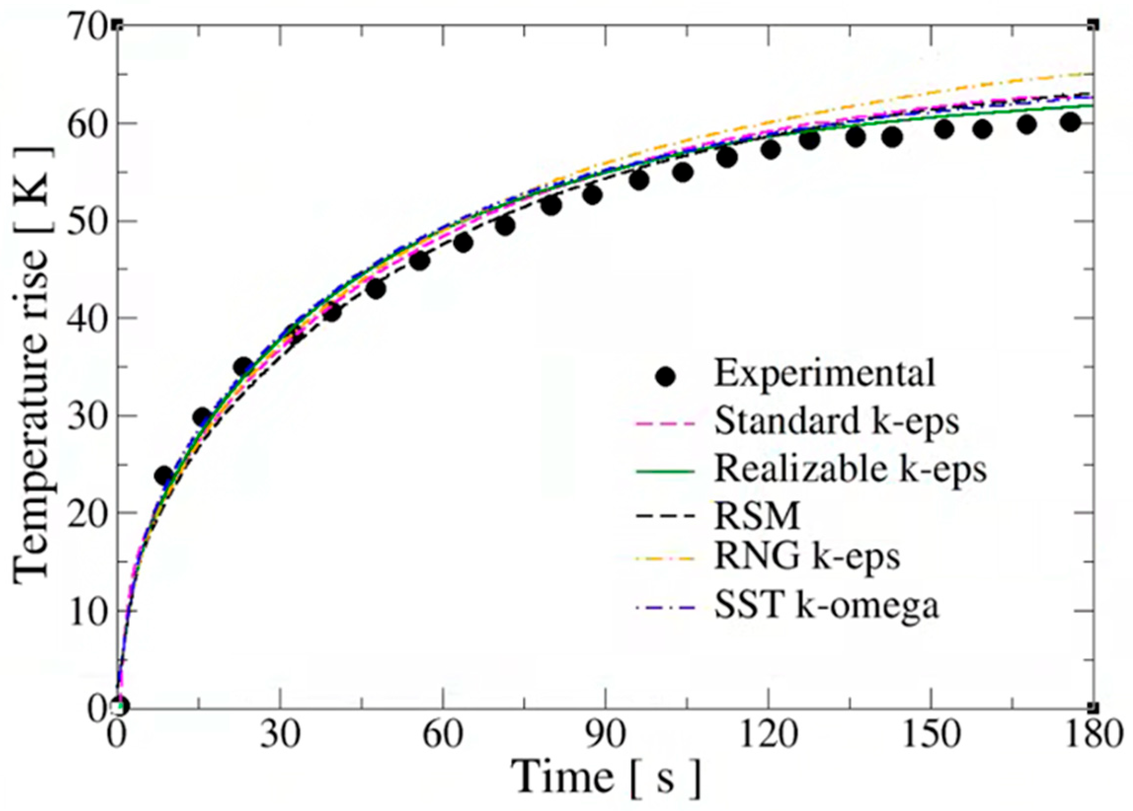
As observed in Figure A1, all models reproduce the main experimental trend reasonably well, namely the rapid temperature increase during the initial stages of refueling followed by a progressive reduction in the heating rate as the cylinder pressure approaches the final filling conditions. The differences among the models remain relatively moderate throughout the transient process, indicating that the global thermal behavior is captured consistently regardless of the turbulence closure employed. However, noticeable deviations appear at intermediate and late filling stages, particularly after approximately 80–100 s, when the sensitivity of the thermal field to turbulent mixing and jet development becomes more significant.
Among the models considered, the realizable k–ε formulation provides the closest agreement with the experimental measurements over most of the filling process. This improved performance can be attributed to its enhanced capability to represent the spreading and decay rates of the inlet jet [70,71], as well as the associated turbulent strain rates generated during hydrogen injection. In fast-filling conditions, the flow inside the cylinder is dominated by a highly transient turbulent jet, whose expansion strongly affects the mixing process and consequently the spatial and temporal temperature distribution. The realizable k–ε model incorporates an improved formulation of the turbulent viscosity and dissipation equations, allowing a more accurate prediction of jet expansion and recirculation phenomena compared with the standard k–ε model [65].
By contrast, the RNG k–ε model tends to overpredict the temperature rise during the later stages of filling, whereas the standard k–ε, SST k–ω and RSMs exhibit intermediate behavior, slightly overestimating the final cylinder temperature. Although all turbulence models reproduce the overall physics of the refueling process reasonably well, the realizable k–ε model provides the best compromise between numerical accuracy, physical realism, and computational cost for the simulation of hydrogen fast-filling processes under the present operating conditions. Consequently, it has been selected for the reminder of the CFD simulations.
References
- Wang, X.; Cheng, T.; Hong, H.; Guo, H.; Lin, X.; Yang, X.; Nie, B.; Hu, Z.; Zou, J. Challenges and opportunities in hydrogen storage and transportation: A comprehensive review. Renew. Sustain. Energy Rev. 2025, 219, 115881. [Google Scholar] [CrossRef] [Scilit]
- International Renewable Energy Agency (IRENA). Global Hydrogen Trade to Meet the 1.5 °C Climate Goal: Part III—Green Hydrogen Cost and Potential; IRENA: Abu Dhabi, United Arab Emirates, 2022. [Google Scholar]
- Rivard, E.; Trudeau, M.; Zaghib, K. Hydrogen storage for mobility: A review. Materials 2019, 12, 1973. [Google Scholar] [CrossRef] [Scilit] [PubMed]
- Ahluwalia, R.K.; Hua, T.Q.; Peng, J.-K. On-Board and Off-Board Performance of Hydrogen Storage Options for Light-Duty Vehicles. Int. J. Hydrogen Energy 2012, 37, 2891–2910. [Google Scholar] [CrossRef] [Scilit]
- Reddi, K.; Elgowainy, A.; Rustagi, N.; Gupta, E. Techno-economic analysis of conventional and advanced high-pressure tube trailer configurations for compressed hydrogen gas transportation and refueling. Int. J. Hydrogen Energy 2018, 43, 4428–4438. [Google Scholar] [CrossRef] [Scilit]
- Ko, K.; Kim, C. Attention-Based Hydrogen Refueling Imputation Model for Efficient Hydrogen Refueling Stations. Appl. Sci. 2024, 14, 10332. [Google Scholar] [CrossRef] [Scilit]
- Stein, A.; Nolte, B.; Kizgin, U.V.; Grünewald, O.; Yurtseven, G.; Vietor, T. Relationship Between Area and Capacity of Hydrogen Refueling Stations and Derivation of Design Recommendations. Hydrogen 2025, 6, 16. [Google Scholar] [CrossRef] [Scilit]
- Zhang, L.; Wu, Q.; Liu, M.; Chen, H.; Wang, D.; Li, X.; Ba, Q. Hydrogen Leakage Location Prediction in a Fuel Cell System of Skid-Mounted Hydrogen Refueling Stations. Energies 2025, 18, 228. [Google Scholar] [CrossRef] [Scilit]
- Xu, H.; Fang, Y.; Zhou, M.-Y.; Wang, X.; Wang, R.; Dai, Y.-M.; Li, J.-C.; Li, J.-Q.; Kwon, J.-T. Application and Research Progress of Mechanical Hydrogen Compressors in Hydrogen Refueling Stations: Structure, Performance, and Challenges. Machines 2025, 13, 1015. [Google Scholar] [CrossRef] [Scilit]
- Bezrukovs, V.; Bezrukovs, V.; Konuhova, M.; Bezrukovs, D.; Kaldre, I.; Popovs, A.I. Numerical Simulations of Thermodynamic Processes in the Chamber of a Liquid Piston Compressor for Hydrogen Applications. Technologies 2024, 12, 266. [Google Scholar] [CrossRef] [Scilit]
- Olmos, F.; Manousiouthakis, V.I. Hydrogen car fill-up process modeling and simulation. Int. J. Hydrogen Energy 2013, 38, 3401–3418. [Google Scholar] [CrossRef] [Scilit]
- Zheng, J.; Guo, J.; Yang, J.; Zhao, Y.; Zhao, L.; Pan, X.; Ma, J.; Zhang, L. Experimental and numerical study on temperature rise within a 70 MPa type III cylinder during fast refueling. Int. J. Hydrogen Energy 2013, 38, 10956–10962. [Google Scholar] [CrossRef] [Scilit]
- Elgowainy, A.; Reddi, K.; Lee, D.Y.; Rustagi, N.; Gupta, E. Techno-economic and thermodynamic analysis of pre-cooling systems at gaseous hydrogen refueling stations. Int. J. Hydrogen Energy 2017, 42, 29067–29079. [Google Scholar] [CrossRef] [Scilit]
- Reddi, K.; Elgowainy, A.; Rustagi, N.; Gupta, E. Impact of hydrogen SAE J2601 fueling methods on fueling time of light-duty fuel cell electric vehicles. Int. J. Hydrogen Energy 2017, 42, 16675–16685. [Google Scholar] [CrossRef] [Scilit]
- Dadkhah, A.; Bozalakov, D.; De Kooning, J.D.M.; Vandevelde, L. On the optimal planning of a hydrogen refuelling station participating in the electricity and balancing markets. Int. J. Hydrogen Energy 2021, 46, 1488–1500. [Google Scholar] [CrossRef] [Scilit]
- Reddi, K.; Elgowainy, A.; Rustagi, N.; Gupta, E. Impact of hydrogen refueling configurations and market parameters on the refueling cost of hydrogen. Int. J. Hydrogen Energy 2017, 42, 21855–21865. [Google Scholar] [CrossRef] [Scilit]
- Elgowainy, A.; Reddi, K. Hydrogen fueling station pre-cooling analysis. In DOE Hydrogen and Fuel Cells Program Annual Merit Review and Peer Evaluation Meeting; U.S. Department of Energy: Washington, DC, USA, 2015. [Google Scholar]
- Talpacci, E.; Reuß, M.; Grube, T.; Cilibrizzi, P.; Gunnella, R.; Robinius, M.; Stolten, D. Effect of cascade storage system topology on the cooling energy consumption in fueling stations for hydrogen vehicles. Int. J. Hydrogen Energy 2018, 43, 6256–6265. [Google Scholar] [CrossRef] [Scilit]
- Xiao, L.; Chen, J.; Wu, Y.; Zhang, W.; Ye, J.; Shao, S.; Xie, J. Effects of pressure levels in a three-cascade storage system on the overall energy consumption in hydrogen refueling stations. Int. J. Hydrogen Energy 2021, 46, 31334–31345. [Google Scholar] [CrossRef] [Scilit]
- Wen, C.; Rogie, B.; Kærn, M.R.; Rothuizen, E. A first study of the potential of integrating an ejector in hydrogen fuelling stations for fuelling high-pressure hydrogen vehicles. Appl. Energy 2020, 260, 113958. [Google Scholar] [CrossRef] [Scilit]
- Chen, J.; Gao, X.; Shao, S.; Hu, H.; Xie, J.; Li, N.; Gao, N. Numerical investigation of the vortex tube performance in novel precooling methods in hydrogen fueling stations. Int. J. Hydrogen Energy 2021, 46, 5548–5555. [Google Scholar] [CrossRef] [Scilit]
- Morgese, G.; Fornarelli, F.; Oresta, P.; Capurso, T.; Stefanizzi, M.; Camporeale, S.M.; Torresi, M. Fast design procedure for turboexpanders in pressure energy recovery applications. Energies 2020, 13, 3669. [Google Scholar] [CrossRef] [Scilit]
- Yoshida, J.; Matsuo, E.; Takata, Y.; Monde, M. Thermodynamic analysis of high-pressure hydrogen gas refueling system with turbo-expanders. Mech. Eng. J. 2019, 6, 18–00388. [Google Scholar] [CrossRef] [Scilit]
- Chen, J.; Xiao, L.; Wu, Y.; Gao, X.; Chen, H.; Xie, J.; Shao, S. Dynamic simulation of the potential of integrating a turbo-expander in a hydrogen refueling station. Appl. Therm. Eng. 2022, 202, 117889. [Google Scholar] [CrossRef] [Scilit]
- Singer, G.; Köll, R.; Aichhorn, L.; Pertl, P.; Trattner, A. Utilizing hydrogen pressure energy by expansion machines—PEM fuel cells in mobile and other potential applications. Appl. Energy 2023, 343, 121056. [Google Scholar] [CrossRef] [Scilit]
- Post, M.; Leighton, D.; Bran-Anleu, G.; Hecht, E.S.; Wiryadinata, S.; Ehrhart, B.D.; Conboy, T. Turboexpander for Direct Cooling in Hydrogen Vehicle Fueling Infrastructure; National Renewable Energy Laboratory: Golden, CO, USA, 2023; NREL/TP-5700-86669. Available online: https://docs.nlr.gov/docs/fy24osti/86669.pdf (accessed on 20 May 2026).
- Chen, Y.; Li, H.; Che, X.; Ren, G.; Zhang, Z.; Li, Q.; Cai, W. A parallel-expander configuration for high-efficiency hydrogen refueling station. Int. J. Hydrogen Energy 2026, 209, 153591. [Google Scholar] [CrossRef] [Scilit]
- O’Brien, J.M.; Young, T.M.; Early, J.M.; Griffin, P.C. An assessment of commercial CFD turbulence models for near wake HAWT modelling. J. Wind. Eng. Ind. Aerodyn. 2018, 176, 32–53. [Google Scholar] [CrossRef] [Scilit]
- Laín, S.; García, M.J.; Quintero, B.; Orrego, S. CFD numerical simulations of Francis turbines. Rev. Fac. Ing. Univ. Antioq. 2010, 51, 31–40. [Google Scholar] [CrossRef] [Scilit]
- Khoshvaght-Aliabadi, M.; Ghodrati, P.; Mahian, O.; Kang, Y.T. CFD study of rib-enhanced printed circuit heat exchangers for precoolers in solar power plants’ supercritical CO2 cycle. Energy 2024, 292, 130418. [Google Scholar] [CrossRef] [Scilit]
- Nassini, P.C.; Pampaloni, D.; Meloni, R.; Andreini, A. Lean blow-out prediction in an industrial gas turbine combustor through a LES-based CFD analysis. Combust. Flame 2021, 229, 111391. [Google Scholar] [CrossRef] [Scilit]
- Baratta, M.; Chiriches, S.; Goel, P.; Misul, D. CFD modelling of natural gas combustion in IC engines under different EGR dilution and H2-doping conditions. Transp. Eng. 2020, 2, 100018. [Google Scholar] [CrossRef] [Scilit]
- Chaturvedi, S.; Santhosh, R.; Mashruk, S.; Yadav, R.; Valera-Medina, A. Prediction of NOx emissions and pathways in premixed ammonia-hydrogen-air combustion using CFD-CRN methodology. J. Energy Inst. 2023, 111, 101406. [Google Scholar] [CrossRef] [Scilit]
- Tarodiya, R.; Khullar, S.; Levy, A. Particulate flow and erosion modeling of a Pelton turbine injector using CFD-DEM simulations. Powder Technol. 2022, 399, 117168. [Google Scholar] [CrossRef] [Scilit]
- Krzemianowski, Z.; Kaniecki, M. Low-head high specific speed Kaplan turbine for small hydropower—Design, CFD loss analysis and basic, cavitation and runaway investigations: A case study. Energy Convers. Manag. 2023, 276, 116558. [Google Scholar] [CrossRef] [Scilit]
- Ahmed, S.; Hassan, A.; Zubair, R.; Rashid, S.; Ullah, A. Design modification in an industrial multistage orifice to avoid cavitation using CFD simulation. J. Taiwan Inst. Chem. Eng. 2023, 148, 104833. [Google Scholar] [CrossRef] [Scilit]
- Teran, L.A.; Laín, S.; Rodríguez, S.A. Synergy effect modelling of cavitation and hard particle erosion: Implementation and validation. Wear 2021, 478–479, 203901. [Google Scholar] [CrossRef] [Scilit]
- Tushar Choudahry, S. Computational analysis of IR-SOFC: Thermodynamic, electrochemical process and flow configuration dependency. Int. J. Hydrogen Energy 2016, 41, 1259–1271. [Google Scholar] [CrossRef] [Scilit]
- Gadhewal, R.; Ananthula, V.V.; Patnaikuni, V.S. CFD simulation of hot spot in PEM fuel cell with diverging and converging flow channels. Mater. Today Proc. 2023, 72, 410–416. [Google Scholar] [CrossRef] [Scilit]
- Zhang, L.; Yu, X.; Lv, Q.; Cao, F.; Wang, X. Study of transient indoor temperature for a HVAC room using a modified CFD method. Energy Procedia 2019, 160, 420–427. [Google Scholar] [CrossRef] [Scilit]
- Lain, S.; Sommerfeld, M.; Quintero, B. Numerical simulation of secondary flow in pneumatic conveying of solid particles in a horizontal circular pipe. Braz. J. Chem. Eng. 2009, 26, 583–594. [Google Scholar] [CrossRef] [Scilit]
- Zhang, J.; Poon, K.H.; Kwok, H.H.L.; Hou, F.; Cheng, J.C.P. Predictive control of HVAC by multiple output GRU—CFD integration approach to manage multiple IAQ for commercial heritage building preservation. Build. Environ. 2023, 245, 110802. [Google Scholar] [CrossRef] [Scilit]
- Lain, S.; Sommerfeld, M. A study of the pneumatic conveying of non-spherical particles in a turbulent horizontal channel flow. Braz. J. Chem. Eng. 2007, 24, 535–546. [Google Scholar] [CrossRef] [Scilit]
- Islam, M.T.; Chen, Y.; Seong, D.; Verhougstraete, M.; Son, Y.J. Effects of recirculation and air change per hour on COVID-19 transmission in indoor settings: A CFD study with varying HVAC parameters. Heliyon 2024, 10, e35092. [Google Scholar] [CrossRef] [Scilit] [PubMed]
- Goz, M.F.; Lain, S.; Sommerfeld, M. Study of the numerical instabilities in Lagrangian tracking of bubbles and particles in two-phase flow. Comp. Chem. Eng. 2004, 28, 2727–2733. [Google Scholar] [CrossRef] [Scilit]
- Xie, H.; Makarov, D.; Kashkarov, S.; Molkov, V. Comparative analysis of CFD models to simulate temperature non-uniformity during hydrogen tank refuelling. Int. J. Hydrogen Energy 2024, 70, 715–728. [Google Scholar] [CrossRef] [Scilit]
- Zhao, Y.; Liu, G.; Liu, Y.; Zheng, J.; Chen, Y.; Zhao, L.; Guo, J.; He, Y. Numerical Study on Fast Filling of 70 MPa Type III Cylinder for Hydrogen Vehicle. Int. J. Hydrogen Energy 2012, 37, 17517–17522. [Google Scholar] [CrossRef] [Scilit]
- Ramasamy, V.; Richardson, E. Thermal response of high-aspect-ratio hydrogen cylinders undergoing fast-filling. Int. J. Heat Mass Transf. 2020, 160, 120179. [Google Scholar] [CrossRef] [Scilit]
- Hall, C.; Ramasamy, V. Modelling the conjugate heat transfer during the fast-filling of high-pressure hydrogen vessels for vehicular transport. Int. J. Thermofluids 2024, 21, 100527. [Google Scholar] [CrossRef] [Scilit]
- Martin, J.; Nouvelot, Q.; Ren, V.; Lodier, G.; Vyazmina, E.; Ammouri, F.; Carrere, P. CFD simulations of the refueling of long horizontal H2 tanks with tilted injector. Int. J. Hydrogen Energy 2024, 54, 562–573. [Google Scholar] [CrossRef] [Scilit]
- Gonin, R.; Horgue, P.; Guibert, R.; Fabre, D.; Bourguet, R.; Ammouri, F.; Vyazmina, E. A computational fluid dynamic study of the filling of a gaseous hydrogen tank under two contrasted scenarios. Int. J. Hydrogen Energy 2022, 47, 23278–23292. [Google Scholar] [CrossRef] [Scilit]
- Mokhtari, B.; Guessab, A.; Rekiouk, Y.; Hamza, B. The fast filling process of hydrogen tanks by simulations based on the CFD code. Numer. Heat Transf. Part A Appl. 2025, 87, 2527400. [Google Scholar] [CrossRef] [Scilit]
- Suryan, A.; Kim, H.D.; Setoguchi, T. Comparative study of turbulence models performance for refueling of compressed hydrogen tanks. Int. J. Hydrogen Energy 2013, 38, 9562–9569. [Google Scholar] [CrossRef] [Scilit]
- Galassi, M.C.; Papanikolaou, E.; Heitsch, M.; Baraldi, D.; Acosta-Iborra, B.; Moretto, P. Assessment of CFD models for hydrogen fast filling simulations. Int. J. Hydrogen Energy 2014, 39, 6252–6260. [Google Scholar] [CrossRef] [Scilit]
- Xie, H.; Makarov, D.; Kashkarov, S.; Molkov, V. CFD simulations of hydrogen tank fuelling: Sensitivity to turbulence model and grid resolution. Hydrogen 2023, 4, 1001–1021. [Google Scholar] [CrossRef] [Scilit]
- Galassi, M.C.; Baraldi, D.; Moretto, P. CFD Analysis of Fast Filling Scenarios for 70 MPa Hydrogen Type IV Cylinders. Int. J. Hydrogen Energy 2012, 37, 6886–6892. [Google Scholar] [CrossRef] [Scilit]
- Melideo, D.; Baraldi, D.; Acosta-Iborra, B.; Ortiz Cebolla, R.; Moretto, P. CFD simulations of filling and emptying of hydrogen tanks. Int. J. Hydrogen Energy 2017, 42, 7304–7313. [Google Scholar] [CrossRef] [Scilit]
- Melideo, D.; Baraldi, D.; Galassi, M.C.; Cebolla, R.O.; Iborra, B.A.; Moretto, P. CFD model performance benchmark of fast filling simulations of hydrogen tanks with pre-cooling. Int. J. Hydrogen Energy 2014, 39, 4389–4395. [Google Scholar] [CrossRef] [Scilit]
- Bilgili, M.; Yumşakdemir, R.F. Effects of real gas equations on the fast-filling process of compressed hydrogen storage tank. Int. J. Hydrogen Energy 2024, 53, 816–828. [Google Scholar] [CrossRef] [Scilit]
- Bourgeois, T.; Ammouri, F.; Baraldi, D.; Moretto, P. The temperature evolution in compressed gas filling processes: A review. Int. J. Hydrogen Energy 2018, 43, 2268–2292. [Google Scholar] [CrossRef] [Scilit]
- Li, H.; Lyu, Z.; Liu, Y.; Han, M.; Li, H. The effects of infill on hydrogen tank temperature distribution during fast fill. Int. J. Hydrogen Energy 2021, 46, 10396–10410. [Google Scholar] [CrossRef] [Scilit]
- Cui, W.; Yuan, Y.; Wang, H.; Tong, L. Numerical investigation on the influence of geometrical parameters on the temperature distribution in marine hydrogen storage tanks during filling. Int. J. Hydrogen Energy 2024, 51, 61–71. [Google Scholar] [CrossRef] [Scilit]
- Ebne-Abbasi, H.; Makarov, D.; Molkov, V. CFD model of refuelling through the entire equipment of a hydrogen refuelling station. Int. J. Hydrogen Energy 2024, 53, 200–207. [Google Scholar] [CrossRef] [Scilit]
- Leachman, J.W.; Jacobsen, R.T.; Penoncello, S.G.; Lemmon, E.W. Fundamental equations of state for parahydrogen, normal hydrogen, and orthohydrogen. J. Phys. Chem. Ref. Data 2009, 38, 721–748. [Google Scholar] [CrossRef] [Scilit]
- Shih, T.-H.; Liou, W.W.; Shabbir, A.; Yang, Z.; Zhu, J. A New k–ε Eddy-Viscosity Model for High Reynolds Number Turbulent Flows: Model Development and Validation. Comput. Fluids 1995, 24, 227–238. [Google Scholar] [CrossRef] [Scilit]
- ANSYS Inc. ANSYS Fluent User’s Guide, Release 2023 R2; ANSYS Inc.: Canonsburg, PA, USA, 2023. [Google Scholar]
- Willmott, C.J.; Matsuura, K. Advantages of the Mean Absolute Error (MAE) over the Root Mean Square Error (RMSE) in Assessing Average Model Performance. Clim. Res. 2005, 30, 79–82. [Google Scholar] [CrossRef] [Scilit]
- Liu, H.; Zuo, J.; Qiu, S.; Liang, Y.; Ke, C.; Liu, L.; Peng, N.; Xiong, L.; Li, K.; Zhang, X. Simulative and experimental analysis of high-speed helium turbo-expanders in a 5 t/day hydrogen liquefier. Int. J. Hydrogen Energy 2025, 133, 152–164. [Google Scholar] [CrossRef] [Scilit]
- Gu, C.; Zhu, S.; Liu, Z.; Qiu, L.; Liu, Y.; Fang, K.; Li, J. Load characteristics and dynamic stability of hydrogen aerostatic gas bearings in turbo-expanders. J. Zhejiang Univ. Sci. A 2026, 27, 598–609. [Google Scholar] [CrossRef] [Scilit]
- Lain, S.; Aliod, R. Study on the Eulerian dispersed phase equations in non-uniform turbulent two-phase flows: Discussion and comparison with experiments. Int. J. Heat Fluid Flow 2000, 21, 341–380. [Google Scholar] [CrossRef] [Scilit]
- Laín, S.; García, J.A. Study of four-way coupling on turbulent particle-laden jet flows. Chem. Eng. Sci. 2006, 61, 6775–6785. [Google Scholar] [CrossRef] [Scilit]
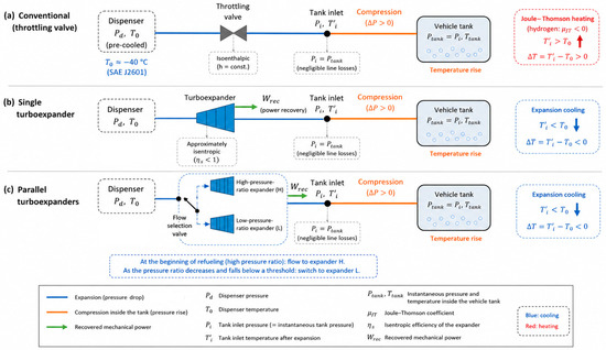
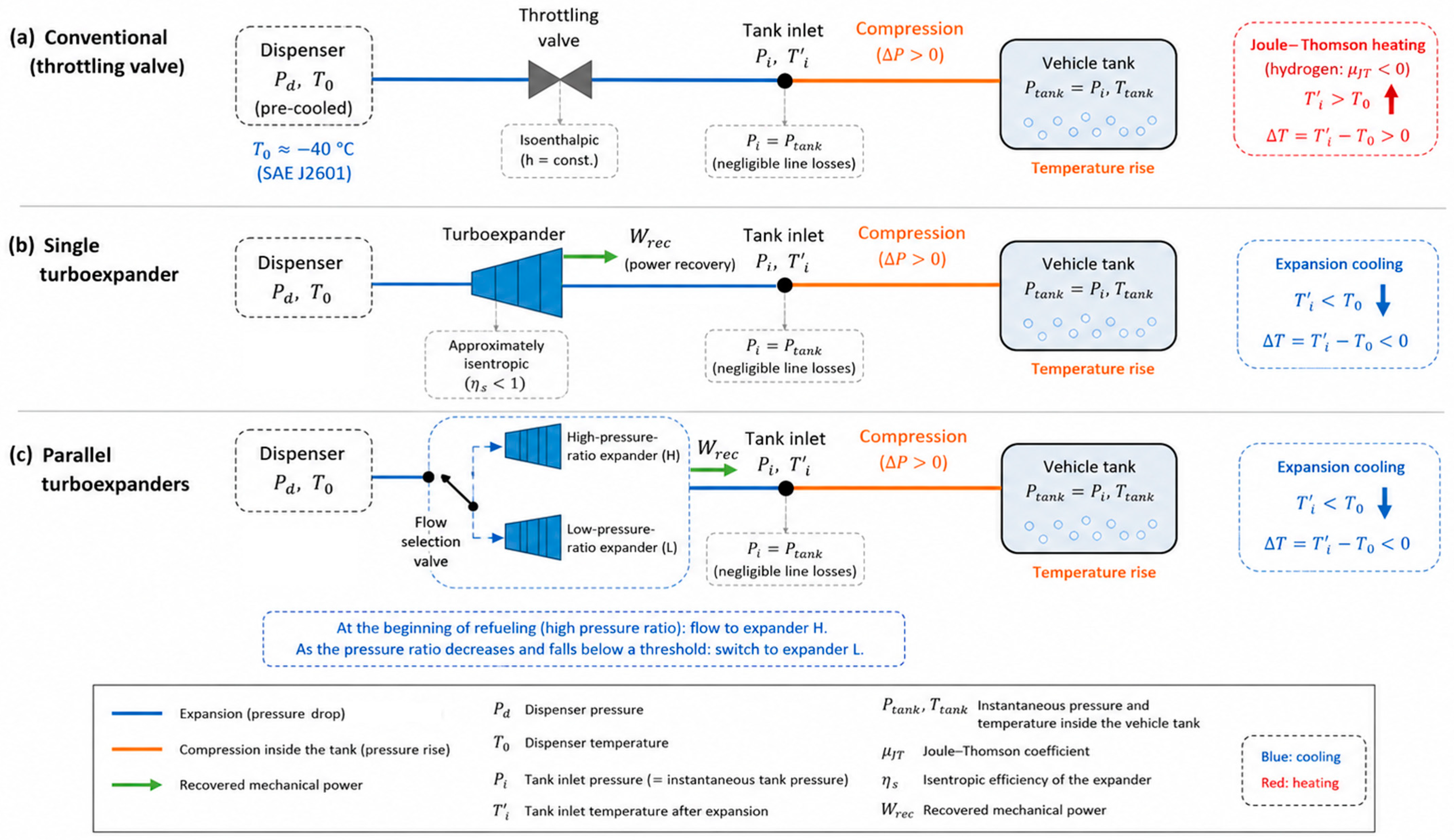
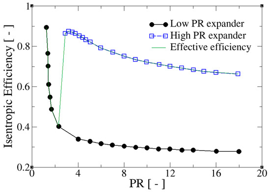
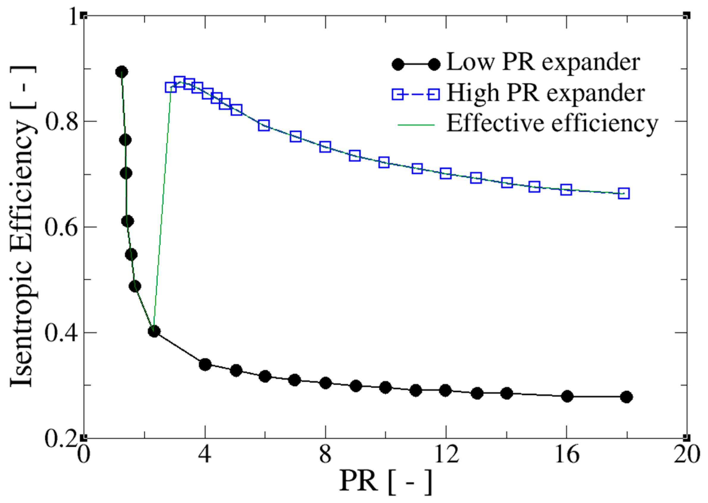
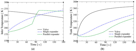
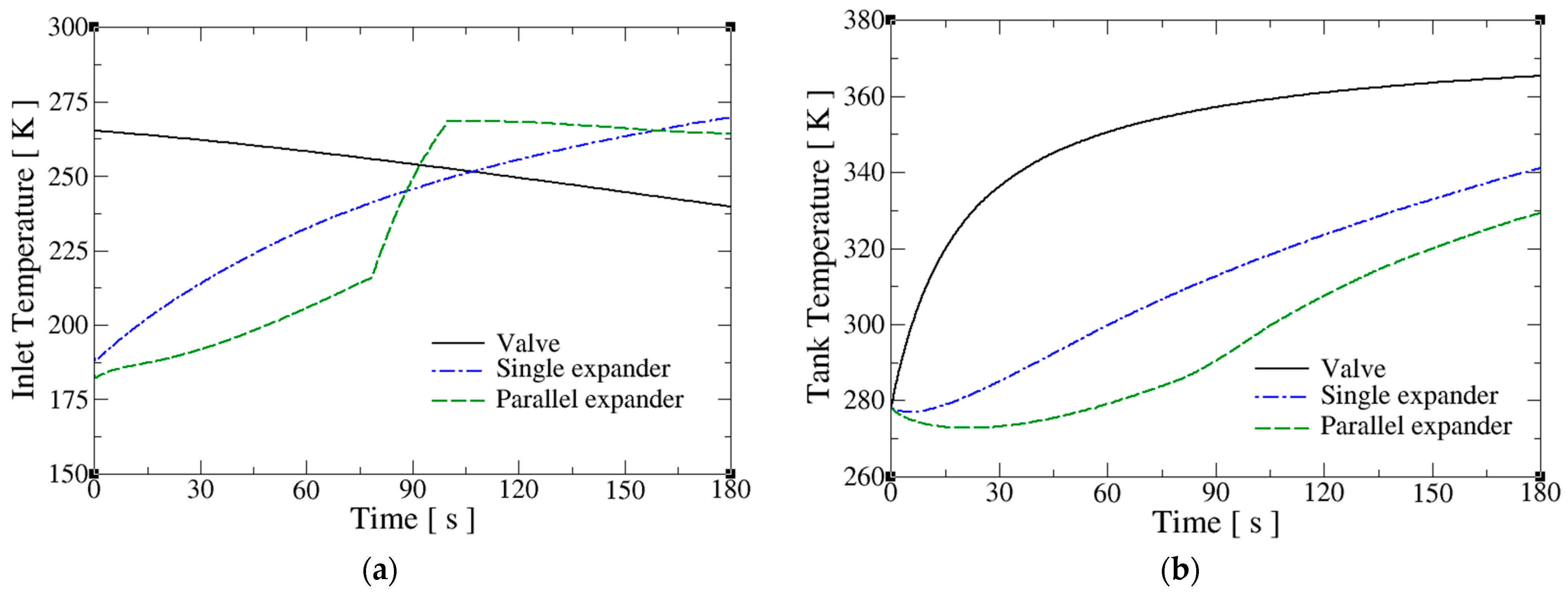
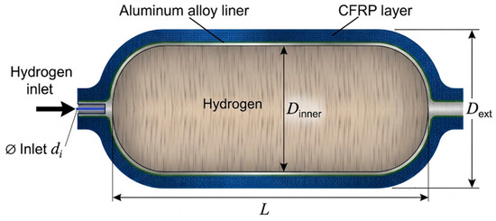
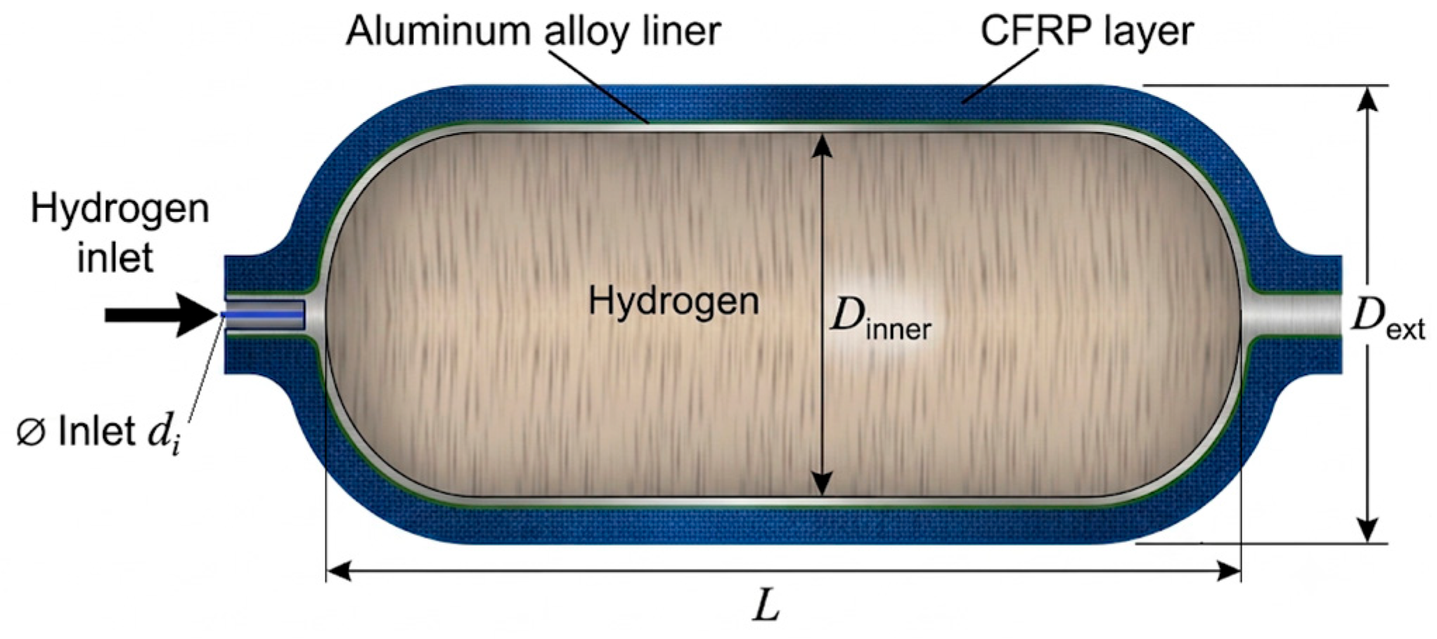
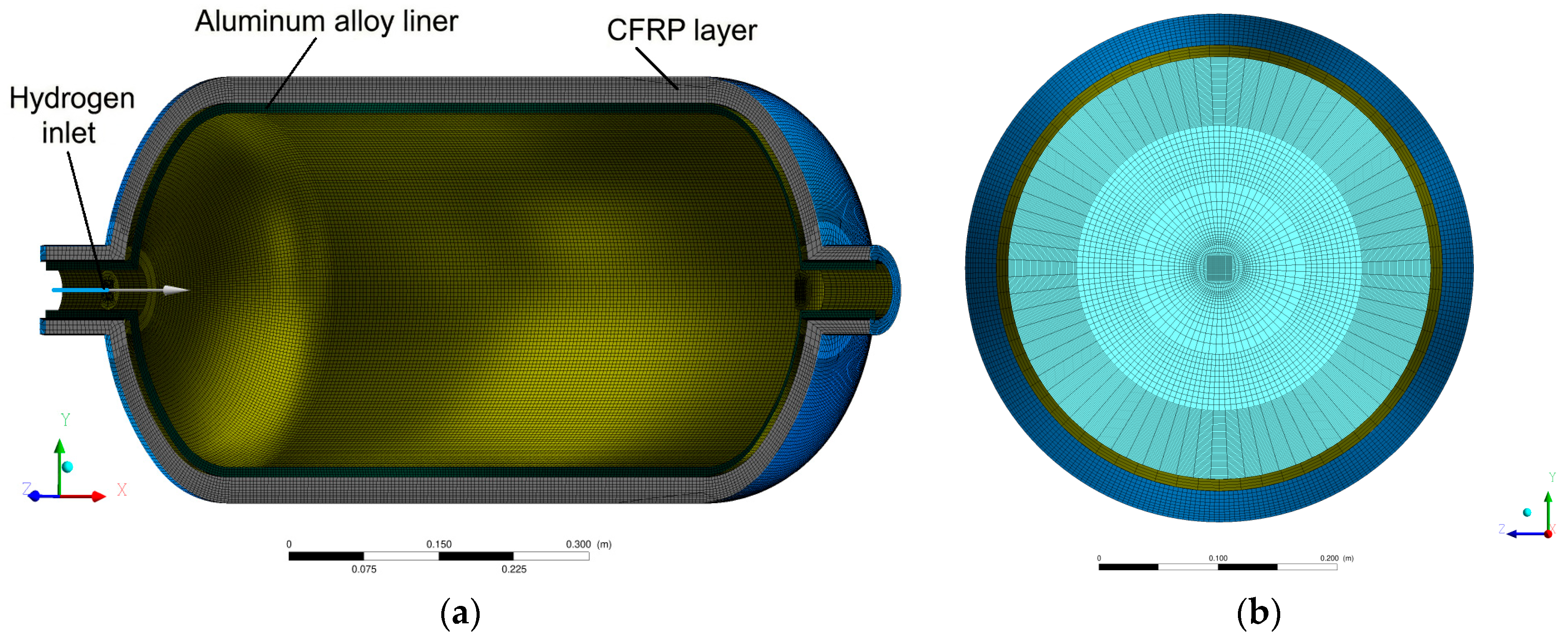
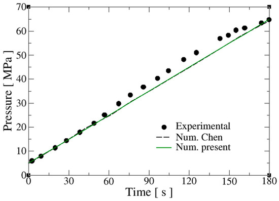
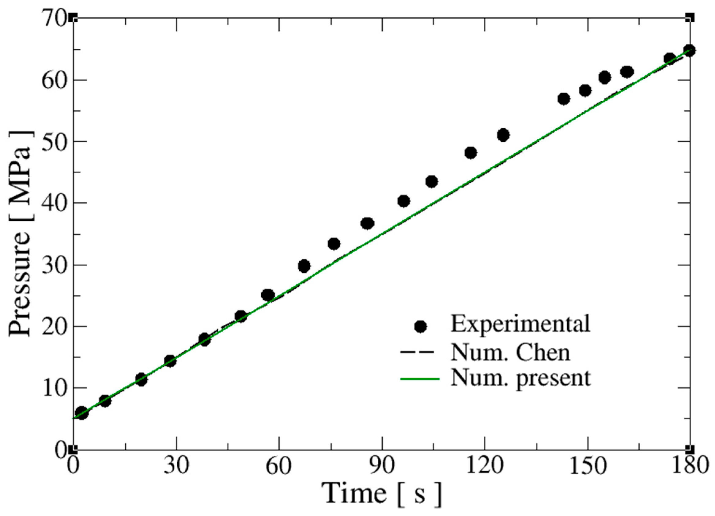
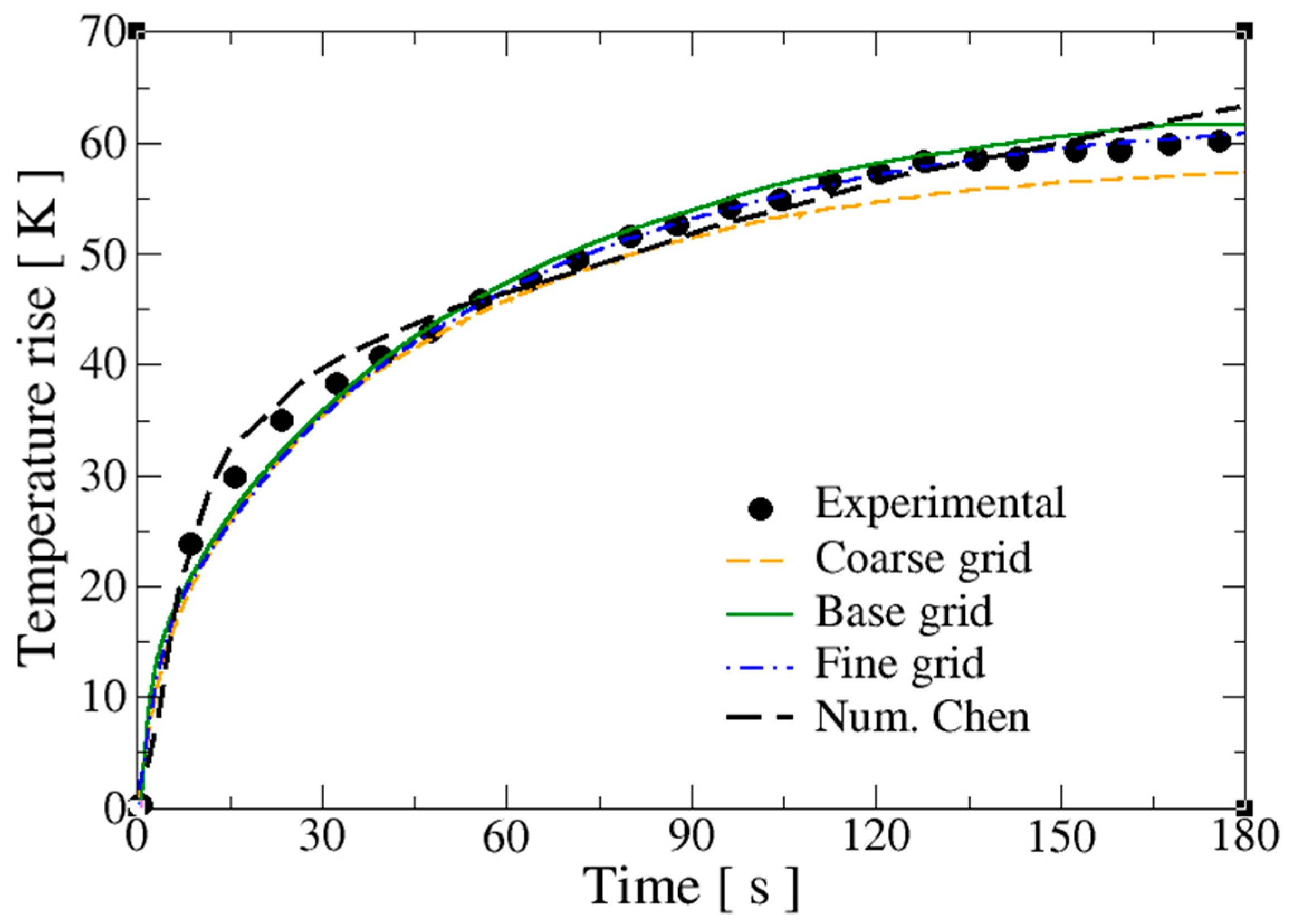
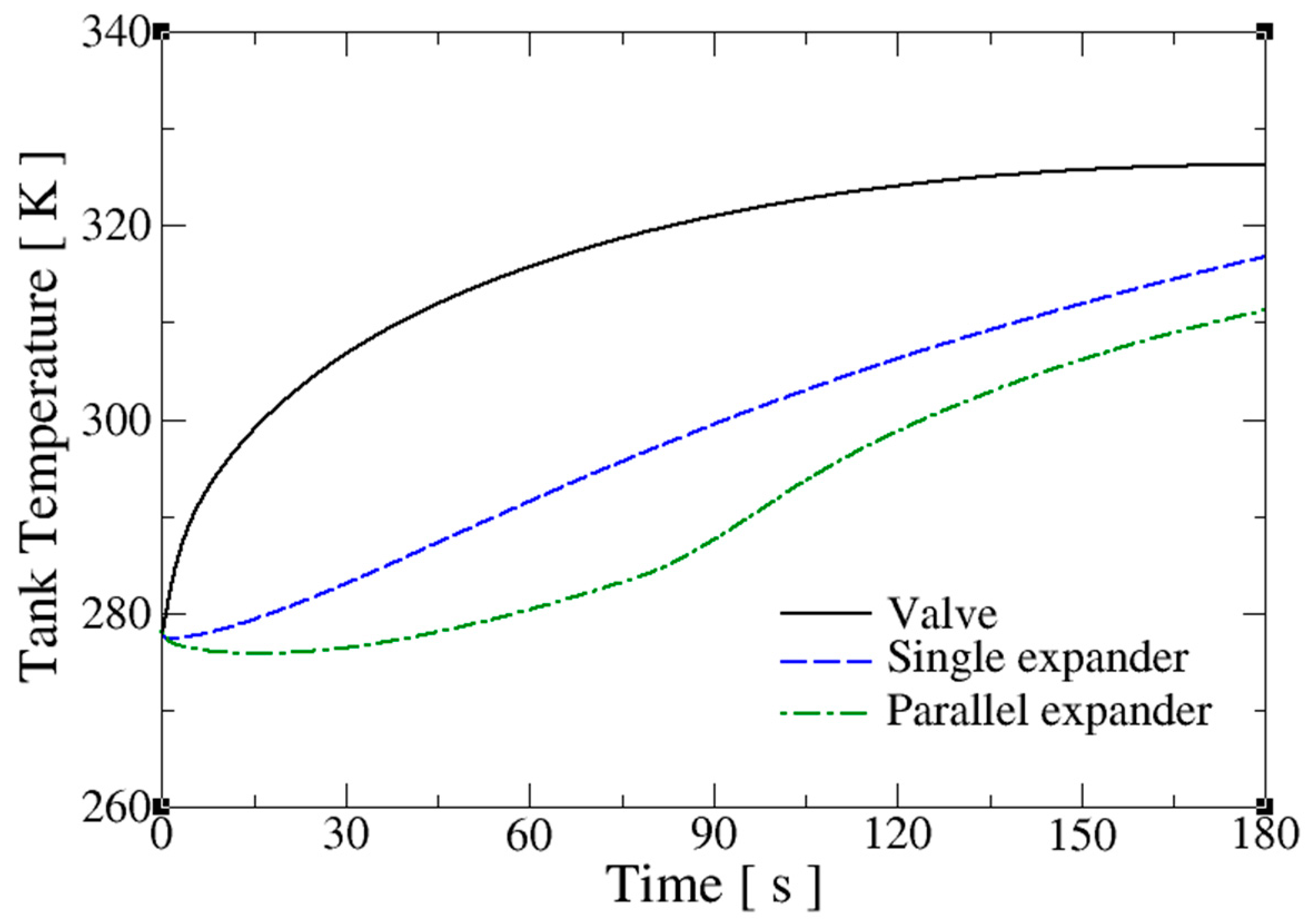
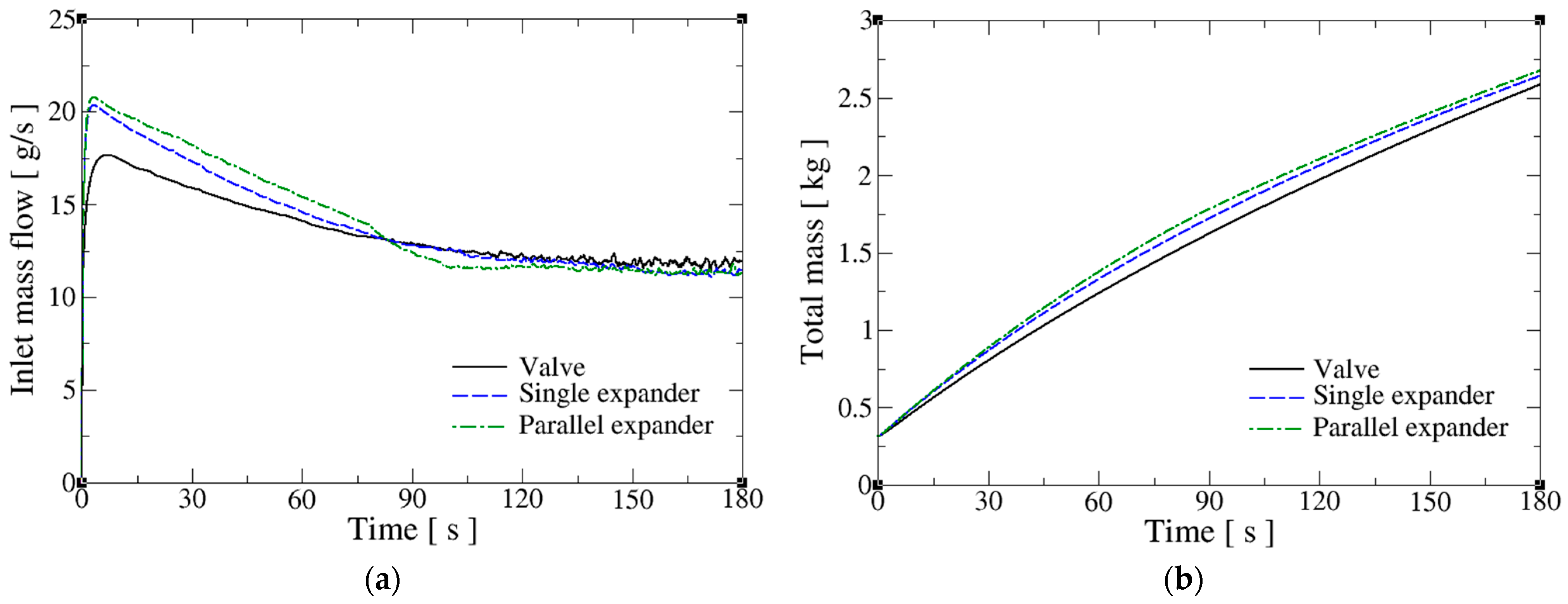
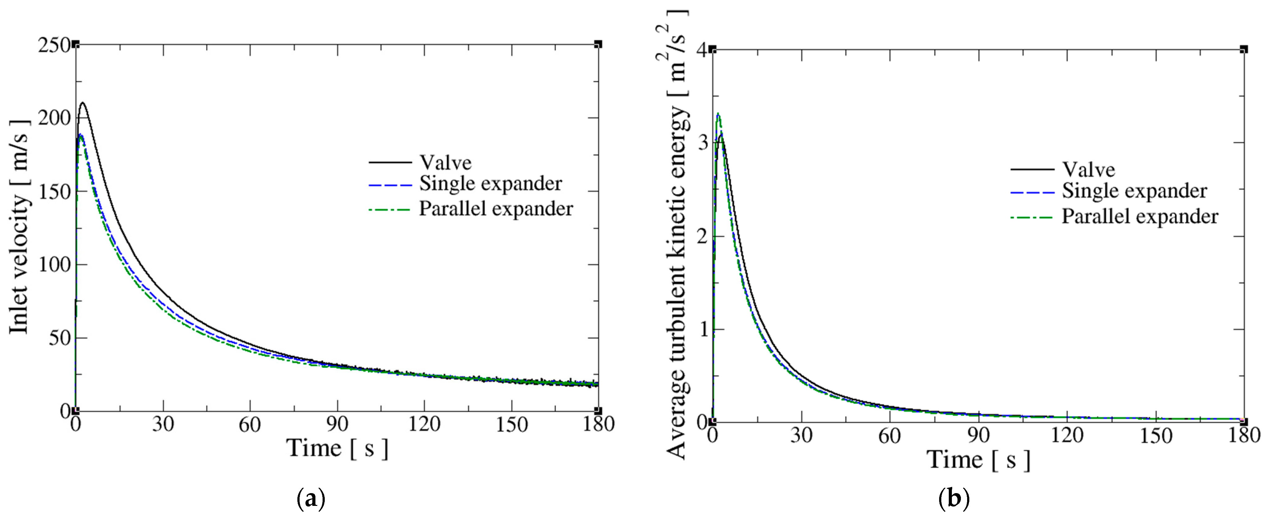

Disclaimer/Publisher’s Note: The statements, opinions and data contained in all publications are solely those of the individual author(s) and contributor(s) and not of MDPI and/or the editor(s). MDPI and/or the editor(s) disclaim responsibility for any injury to people or property resulting from any ideas, methods, instructions or products referred to in the content. |
© 2026 by the authors. Licensee MDPI, Basel, Switzerland. This article is an open access article distributed under the terms and conditions of the Creative Commons Attribution (CC BY) license.