


Abstract
The research investigates lubrication characteristics of a three-stage planetary transmission system under first and second gear conditions. A whole-system CFD model and a planetary carrier bearing CFD model are established. Oil distribution is simulated using a UDF dynamic mesh technique. A dedicated test bench is designed and built for a multi-stage planetary transmission system to measure oil flow data at the outlets of each planetary stage. By comparing the simulation and experimental results, the CFD model is confirmed. The oil distribution in the planetary transmission system is followed. In the first gear condition, the oil distribution within the second stage is significantly lower than that in the other two stages, and mainly converges onto the meshing surfaces of gears. In the second gear condition, the planetary carrier remained stationary, resulting in limited oil distribution in the first stage. Meanwhile, the third-stage planetary carrier bearings exhibit insufficient oil distribution across different gear conditions. To address this issue, several structural optimization structures for the numerical model of the third-stage planetary carrier bearings are compared in terms of theoretical oil supply rates and oil volume fraction distribution characteristics. Among these, constrained by the fixed positions between the oil inlet and oil holes, the structures with different numbers of oil holes in the planetary carrier lead to an oil flow rate reduction due to flow division and pressure loss induced by turbulence at high rotational speed, failing to meet the oil demand. Optimization of oil-hole diameter enlargement, the oil flow rate increases proportionally with the hole diameter. A diameter of 5 mm satisfies the theoretical oil flow rate demand, yet an asymmetric oil distribution is observed between the two inner bearings. Building upon the initial design with two oil holes, a 5 mm diameter design, a 1 mm axial leftward offset of the oil hole position, and a 20° oil-guiding inclination on the outer hub reduce the oil distribution asymmetry between the two inner bearings from 64.5% to 13%. The oil volume fraction increases from 0.005 to 0.069 in the inner bearing and from 0.001 to 0.013 in the outer bearing, resulting in a substantial improvement in overall bearing lubrication performance.
1. Introduction
Multi-stage planetary transmission systems serve as critical components in aero-space and automotive transmission applications, owing to their high power density, compact structure, large transmission ratio, efficient material utilization, even load distribution, light weight, high inner space utilization, and excellent transmission performance. Nevertheless, the system demands high precision in component manufacturing and assembly. Dynamic unbalance tends to occur easily in structures with numerous planetary gears. Lubrication performance of essential components such as gears, bearings, and planetary carriers within the system is ensured by the combined effects of oil supply from the oil passages and centrifugal oil splashing under operating conditions. Inadequate lubrication would significantly impact the transmission efficiency and the reliability of the system. Thus, investigating the lubrication characteristics of the meshing gears and supporting bearings in each planetary stage is critical for multi-stage planetary transmission systems. Researchers have carried out a number of studies on the lubrication flow characteristics of multi-stage planetary transmission systems and inter-stage bearings.
Many researchers have investigated the lubrication characteristics in multi-stage planetary transmission systems through both numerical and experimental methods. Liu et al. [1] focused on the forced oil injection lubrication system in high-power gear boxes. They obtained the oil flow rate at each lubrication point as well as the diameters of nozzles and oil passages by calculating the power loss of gears and bearings. However, they did not conduct numerical validation of their model. Based on fluid mechanics theory, Li et al. [2] utilized XFlow software to study the lubrication characteristics of oil passages in heavy-duty vehicle transmissions. Nevertheless, they did not investigate the lubrication performance of internal gears and bearings. Liu et al. [3] and Dai et al. [4] investigated the effects of oil immersion depth, lubricant viscosity, and injection angle on oil distribution via experimental tests and numerical simulations. In contrast, detailed research on oil flow characteristics in multi-stage planetary transmission systems remains absent in their studies. Lu et al. [5] performed splash lubrication simulations on a helicopter intermediate gearbox using the VOF method and dynamic mesh technique based on CFD. Combined with experiments, they identified that the structure of the oil guide pipe was unreasonable. However, their model only considered a pair of bevel gears and did not extend to complex planetary transmission systems. Ouyang et al. [6] investigated the oil jet lubrication characteristics of orthogonal face gears and proposed a thermo-fluid coupled numerical analysis method. Using experimental validation, they examined the gear lubrication performance under various geometric, injection, and layout parameters. In spite of this, their findings have not been extended or validated in complex planetary transmission systems. Mastrone et al. [7] and Mo et al. [8] verified the validity of numerical simulation by adopting diverse simulation software and meshing strategies, combined with experimental tests and simulations under varied boundary conditions. Yet, their studies did not cover the oil distribution characteristics of multi-stage planetary transmission systems. Qian et al. [9] researched the oil characteristics and jet-induced torque in a three-stage planetary gear system, and analyzed the variations in torque with oil flow rate, nozzle diameter, nozzle number, and oil viscosity. In spite of this, they did not investigate the oil distribution characteristics or the lubrication of inter-stage bearings. Hu et al. [10], Zhang et al. [11], and Gong et al. [12] established dedicated test benches to conduct CFD numerical simulations and experimental validations. Their studies targeted the variable-speed transmission system of helicopters, three-stage planetary transmission systems of vehicles and multi-branch rotating oil passages of turbine planetary reducers. The influences of rotational speed, pressure, and oil temperature on the oil flow rate at each outlet were analyzed. However, none of these studies investigated the oil distribution characteristics of gears, bearings, and other internal components.
Research on gear tooth surface friction properties under varied lubrication and different nano lubricating materials include Čukić et al. [13], who put forward an analytical method for gear tooth number calculation. The approach was verified on a Ravigneaux planetary gear set with seven kinematic chains and two degrees of freedom. It helps create more compact and lightweight gear structures and delivers favorable dynamic performance. Nevertheless, this method fails to consider strength, dynamic, and lubrication limitations, leading to limited application adaptability. Trzepieciński et al. [14] adopted commonly used DC04 low-carbon steel sheets for automobiles as research samples. They explored the effects of edible and non-edible oils on friction coefficients under diverse boundary conditions via strip tensile tests. The results proved non-edible oils can effectively reduce the friction coefficient of steel sheets. However, the study did not test extreme working conditions such as high temperature and heavy load, nor analyze lubrication stability during long-term operation. Zapletal et al. [15], Hartinger et al. [16], and Ding et al. [17] conducted numerical simulations and experimental tests. They verified that gear surface roughness serves as a core factor affecting EHL transition, which greatly alters oil film formation and friction behavior. Their findings provided reliability predictions for complex gear meshing under lubricated conditions, yet lack validation across various lubricants and working conditions. Ebner et al. [18] and Sun et al. [19] conducted experimental tests and dynamic simulations on a FZG twin-disk tester and on timing gears within a marine diesel engine multi-branch shaft system. Their work revealed how different manufacturing methods affect friction coefficient, oil film thickness, and fluid load-carrying capacity. They also proposed installing vibration dampers to improve lubrication and reduce wear. However, their studies did not adequately analyze the effects of different lubricant types or the influence of surface texture on oil film formation. Jiao [20], Shahnazar [21], and Alves [22] separately adopted alumina-silica composite nanoparticles, metallic, metal oxide, carbon-based and boron-based nanoparticles, as well as 5 nm ultrafine copper oxide nanoparticles as lubricant additives. The results show that modified composite nanoparticles can adhere to friction surfaces and produce a rolling friction effect, which helps reduce the friction coefficient. Meanwhile, Huang [23] and S. Tarasov [24] studied the lubrication performance of nanofluids applied to high-speed spur gears and engine oil. It is found that lubricants blended with nano additives can attach to friction surfaces, cut the friction coefficient, and greatly alleviate friction and wear. In spite of this, their simulation outcomes lack experimental verification, and relevant research on nano lubricants under high temperature and oxidative conditions remains inadequate.
Studies on planetary transmission bearings and the corresponding structural optimization are summarized as follows: Nitonye et al. [25] established a mathematical representation of the lubricating oil system in a 955 kW tugboat to calculate the cooling oil flow rate for bearings in the shafting, stern tube, and other components. They determined the pump capacity, oil tank, and oil-passage parameters to meet the system’s lubrication and cooling demands. However, no experimental or numerical simulation validation was performed. Jiang et al. [26] researched the lubricant flow rate of oil guiding devices in helicopter intermediate gearboxes under different oil guide pipe parameters using a CFD numerical model, and experimentally validated the effectiveness of their optimization. Yet, their optimized structure requires considerable layout space and lacks detailed optimized parameters for compact multi-stage planetary systems. Zhang et al. [27] and Wang et al. [28] adopted Flowmaster software to analyze heat generation at each lubrication point. The flow demands of individual lubrication points and the total lubricant flow were calculated based on thermal equilibrium conditions. The design method verified through bench tests and road tests was effective. Chen et al. [29] and Gao et al. [30] combined experimental observations with CFD simulations to comparatively analyze the effects of boundary parameters including viscosity, rotational speed, and surface tension, as well as jet and splash lubrication modes on oil distribution. The influencing mechanisms of these factors on bearing performance were revealed. However, the influence of inter-stage transmission on lubrication characteristics in multi-stage planetary systems was not investigated. Wei et al. [31] and Jia et al. [32] carried out structural optimizations such as designing airfoil-shaped bearing cages, thickening gearbox baffles and adding slots. They explored the lubrication performance of gearboxes and bearings under different structures via experimental tests and CFD simulations. In spite of this, simultaneous research on the two structures has not been conducted. Hu et al. [33] and Dai et al. [34] established an oil-gas two-phase flow model for jet lubricated angular contact ball bearings. Combined with CFD simulations and bench tests, they analyzed the effects of rotational speed, oil supply rate and lubricant physical properties on internal oil-gas distribution. Structural optimizations of bearing inner holes and oil injection nozzles were also performed to determine optimal schemes. Nevertheless, such structural layouts and lubrication modes have limitations when applied to compact planetary transmission systems. Hu et al. [35] proposed an innovative method by optimizing the bearing housing structure. CFD simulations were conducted to compare the oil supply rate of the driven shaft bearings before and after optimization, and experimental results validated a 74% increase in oil supply. Nevertheless, their work only focused on structural optimization of the gearbox housing, without corresponding optimization or verification on the gears and bearings themselves. Wei et al. [36] performed oil-air multiphase flow in planetary bearing cavities with a fixed carrier. They observed that oil-air distribution was negatively correlated with rotational speed, which was verified using a visualized test bench. Suggestions were proposed to optimize nozzles or add injection structures, yet no detailed parametric comparisons or analyses were conducted.
Regarding the lubricating characteristics in multi-stage planetary transmission systems and structural optimization of carrier-supported bearings, most previous studies have primarily concentrated on the splash or churning lubrication behavior in a single gear pair. In the research on gear transmission lubrication characteristics, Qian et al. [10] and Liu et al. [3] mainly explored the influence of nozzle design on jet torque and churning lubrication under different oil immersion depths. Hu et al. [9] and Zhang et al. [11] investigated the oil supply characteristics in multi-branch lubrication passages. However, the oil-gas distribution of meshing gears and support bearings in multi-stage planetary gears under different operating boundaries in splash lubrication has not yet been studied. Research on the lubrication of bearing cavities has mainly focused on side-injection lubrication. Lubrication optimization has been conducted by Hu et al. [33] and Wei et al. [36], who investigated parameters such as injection angle, oil supply rate, and cage oil-guiding method. Yet, few studies have focused on the optimization of lubrication characteristics for planetary carrier-supported bearings under the constraints of their compact structure. This paper focuses on a three-stage planetary transmission system, and conducts numerical and experimental verification of oil flow rate for each planetary stage under different boundary conditions by using a test bench. The lubrication characteristics of components in each planetary stage under various operating conditions are analyzed. Structural optimization is carried out on the highly loaded third-stage planetary carrier bearing to improve its oil-air distribution and operational reliability.
2. Numerical Methods
In this study, the CFD numerical model is discretized using a computational mesh to obtain discrete solutions. Since the effect of oil temperature heating is not considered, the fluid motion is governed by the principles of mass and momentum conservation. Meanwhile, the governing equations for the flow field are derived, including the Navier-Stokes momentum equation and the continuity equation.
where , and are the velocity components in the -, -, and - directions, respectively, and is time, is the density.
The governing principle of the fluid momentum equation is that the sum of forces acting on a fluid element, including body forces and surface forces, equals the product of its mass and acceleration, thereby adhering to Newton’s second law. The specific expression of the equation is as follows:
where represents the body force per unit mass acting on the fluid element, is the stress in the direction acting on the plane perpendicular to the axis, and is the static pressure.
2.1. Turbulence Model
In this study, the κ–ε two-equation turbulence model is applied within the RANS framework, with its solution obtained from two independent transport equations. However, by neglecting molecular viscosity, the standard κ–ε model is not applicable to near-wall regions and other flow zones with underdeveloped turbulence. To overcome this issue, the RNG κ–ε model with an additional term introduced in the dissipation rate equation is adopted, which can improve the accuracy for rapidly strained flows. In this article, each component of the planetary transmission system has a large speed difference under various transmission ratios, and the vortex centrifugal force generated in the complex structure cavity will enhance the circumferential and axial turbulence intensities in the near-wall region within the system. Therefore, the RNG κ–ε turbulence model is adopted in this study, where represents the correction term accounting for various Reynolds numbers (). The specific transport equations are as follows,
where is the production due to buoyancy effects, denotes the turbulent kinetic energy production from mean velocity gradients, and are the reciprocals of the effective Prandtl numbers for turbulent dissipation rate and turbulent kinetic energy, respectively; and are the user-defined source items, characterizes the influence of compressible turbulence dilatation on the overall dissipation rate, , , .
2.2. Multi-Phase Flow Model
When a multi-stage planetary transmission system is in either startup or normal operation, during the lubrication of components such as gears and bearings in each planetary stage, a gasoil two-phase mixed flow forms internally. In order to capture the oil-air interface, this study adopts the model of VOF [19] to track the interface between two incompatible fluids. The phase volume fractions in each cell are obtained using this method, and the volume fraction of phase q is given by the following equation.
where denotes the generalized source term of the volume fraction equation; denotes the oil density; represents the oil volume fraction; denotes the oil velocity. Given that only two phases are considered in the planetary transmission system, the equation can be simplified to the following conclusion:
where and are the volume fractions both air and oil. If is 0, no oil exists in the cell; if is 1, the cell is completely filled with oil.
2.3. Dynamic Mesh Model
In a multi-stage planetary transmission system, the shape and position of the mesh within the fluid domain for components such as gears and bearings in each planetary stage vary with time during system startup and operation. In the dynamic mesh method, the mesh evolves in accordance with the motion of the components. The specific governing equations of the dynamic mesh are as follows:
For an arbitrary control volume, the integral conservation equation for a general scalar is:
where is the fluid density; is the velocity vector; is the moving velocity of the mesh; is the diffusion coefficient; is the source term; and is the boundary of the control volume .
By using the first-order backward difference formula, the time derivative term in the above equation can be written as follows:
where n and n + 1 denote the quantities at the current time step and the next time step, respectively. The volume at the (n + 1)-th time level is calculated by the following equation:
where represents the rate of change of the control volume with respect to time. To satisfy the grid conservation law, the time derivative of the control volume is obtained through the following calculation:
where denotes the number of faces on the control volume, and is the area vector of the j-th face. The dot product is computed on each face of the control volume.
where is the volume swept by face j of the control volume over the time interval .
In this work, the rotational speeds of various components in the multi-stage planetary transmission system are defined via a user-defined function (UDF) file to achieve the definition of rotational motion in the dynamic zones.
2.4. Geometric and Physical Parameters
In this paper, a three-stage planetary transmission system is investigated, which is composed of two NGW planetary gear sets each with four planet gears supported by cylindrical roller bearings, and a double planetary gear set with six planet gears supported by cylindrical roller bearings. These components are connected by the main shaft and three planetary carriers that are supported by five planet carrier bearings. The individual components of the transmission system are appropriately simplified. A detailed 3D structure of the three-stage planetary gear sets is presented in Figure 1, which includes the first-stage, second-stage, and third-stage planetary gear sets as well as the oil supply passages. In Figure 1d, lubricating oil is first supplied to each planetary carrier through the main shaft oil passage, and then delivered to the bearings and gears through the planetary gear pin holes and the main shaft oil passage respectively. In this figure, parts sharing the same color are identical, and those with different colors are separate components.
Figure 1.
Oil supply passage and simplified model of the three-stage planetary gear sets ((a) the first-stage planetary gear set; (b) the second-stage planetary gear set; (c) the third-stage planetary gear set; (d) planetary carriers and oil supply passage).
To effectively simulate oil distribution during gear meshing in the planetary gear sets, a tooth surface shifting method is applied at the meshing regions, reducing the tooth thickness and increasing the gear meshing clearance. This method not only ensures the quantity and quality of the mesh in the meshing region but also effectively tracks the oil distribution between the meshing tooth surfaces. The specific planetary gear clearance adjustment model is illustrated in Figure 2: Different colors in the figure represent different components, and the arrows illustrate the simplification of the model.
Figure 2.
Gear meshing clearance control ((a) planetary gear set model; (b) tooth surface shifting method; (c) meshing tooth surfaces).
In this study, bearing lubrication is critical to the efficiency of the overall planetary transmission system. Therefore, appropriate simplifications are applied to the bearings located within each planetary stage and between planetary carriers. These simplifications enable effective analysis of lubrication conditions and facilitate subsequent design optimization. To better monitor oil supply to the bearings, the rolling elements are also simplified. The bearing simplification is shown in Figure 3: Different colors in the figure represent different components, and the arrows illustrate the simplification of the model.
Figure 3.
Bearing locations and model simplification of the multi-stage planetary transmission system ((a) three-stage planetary gear set model; (b) cross-section of the model; (c) simplification of planetary carrier bearings; (d) simplification of planetary gear bearings).
To facilitate better understanding of the model and more accurate definition of the operating boundaries, Table 1 lists the parameters of each component in the three-stage planetary transmission system; Table 2 presents all parameters of the supporting bearings for the planetary carrier and planetary gears.
Table 1.
Gear parameters in a three-stage planetary transmission system.
Table 2.
Parameters of bearings.
This study investigates first gear and second gear operating conditions in a three-stage planetary transmission system. In this system, the first-stage sun gear serves as the power input, and the second- and third-stage gear sets transmit power via the planetary carriers joined to the main shaft. The rotational speeds of the planetary carriers in the second- and third-stage gear sets remain consistent, the rotational speeds of the remaining planetary gears and ring gears are distributed according to different transmission ratios. The speed distribution under different gear positions is detailed in Table 3 and Table 4. Table 5 gives the main physical parameters used in the simulation.
Table 3.
Rotational speeds of components in the three-stage planetary transmission (first gear condition).
Table 4.
Rotational speeds of components in the three-stage planetary transmission (second gear condition).
Table 5.
Physical parameters of simulations.
2.5. Mesh
Fluid domains were extracted for the entire multistage planetary transmission system and the third-stage support bearing chamber. The fluid domain and cross-section model in a three-stage planetary transmission system are shown in Figure 4. The fluid domain and cross-section model of the third-stage support bearing are presented in Figure 5. Different colors in the figure represent different inter-stage models. In Figure 5, green denotes the internal cavity structure, and wireframes illustrate the mounting positions of relevant parts.
Figure 4.
Fluid domain extracted from a three-stage planetary transmission system. ((a) Overall fluid model; (b) cross-section fluid model).
Figure 5.
Bearing fluid domain model. ((a) Overall fluid model; (b) cross-section fluid model).
Unstructured meshes are employed to discretize the extracted fluid domain. Under the 10 mm global mesh size, refined mesh sizes of 2 mm are used in narrow regions such as gear meshing zones and component clearances, with a minimum control size of 0.4 mm. The final mesh consists of 10,702,248 elements and 2,204,896 nodes. The detailed mesh and cross-sectional views of each planetary stage are shown in Figure 6.
Figure 6.
Fluid mesh of the multi-stage planetary transmission system. ((a) Overall mesh model; (b) section A-A; (c) s section B-B; (d) section C-C).
For the bearing fluid domain, adopting the same 10 mm global mesh size, bearing surfaces are refined to 3 mm, and a refined mesh size of 0.2 mm is applied in local clearances and oil holes. The generated grid contains 580,029 elements and 120,513 nodes. The detailed mesh and cross-sectional views are presented in Figure 7.
Figure 7.
Bearing fluid domain mesh. ((a) Overall mesh model; (b) section A-A).
All fluid domain meshes have cell quality and orthogonal quality values above 0.2, fulfilling the criteria for accurate fluid dynamic computations. A 1 × 10⁻⁶ s time step is utilized for the transient analysis, accompanied by 20 iterations in each step.
2.6. Validation of the Numerical Methods
Experiments represent the most direct validation of mechanical performance, as they reflect both the rationality of structural design and the precision of numerical simulations. A dedicated test bench is designed and experiments are performed to verify the numerical method adopted in this work for the lubrication flow field in the three-stage planetary transmission system. The components are shown in Figure 8. The test bench mainly consists of power input, flow control, and flow measurement components. Under the control of the lubricating oil pump station, the oil is supplied to each planetary stage in the test chamber via oil passages. According to the test requirements, the oil is obtained from the oil outlet of each planetary stage using dedicated measuring cups. Figure 9 shows the configuration of the test chamber. The planetary carriers of each stage are separated by partition plates to prevent oil cross-flow between stages. The main drive motor controls the rotational speed through the main shaft. Each of the three stages has an oil outlet with a diameter of 16 mm at the bottom, through which oil is collected and measured via connecting tubes and measuring cups. In the test, the measuring cups have a 5000 mL capacity and a tolerance of ±10 mL. Detailed experimental parameters are provided in Table 6.
Figure 8.
Test bench of the three-stage planetary system.
Figure 9.
Three stage planetary gearbox for experiments. ((a) Experimental test chamber; (b) test chamber layout diagram; (c) internal assembly).
Table 6.
Physical parameters of the validation tests.
The experiment was performed as follows. The rotational speed is controlled via the drive motor connected to the main shaft. During the experiment, the rotational speeds of the main shaft and the second- and third-stage planetary carriers are identical, while the first-stage planetary carrier remains stationary. The oil in the system is supplied by a lubricating oil pump. After the drive motor has operated for 20 s, the test bench stops supplying oil and shuts down. The lubricating oil is then collected continuously for 10 min until the oil volume in the measuring cup stabilizes, which demonstrates that a steady-state condition has been reached. Subsequently, the lubricating oil is gathered using Measuring Cups 1, 2, and 3 located at the oil outlets of each planetary stage, as shown in Figure 10. Each test is conducted three times, with each trial consisting of a complete 620-s data monitoring and acquisition process under three oil pressure conditions at the same rotational speed. Upon completion of data measurement, the lubricating oil in cups is recirculated back to the oil tank until every operating condition has been completed. Figure 11 shows the oil splashing induced by the rotation of the planetary gears, with the lubricating oil accumulating on the transparent cover at the top of each planetary carrier. This suggests that, under the influence of rotational motion, the second and third planetary stages have more oil volume than the first stage.
Figure 10.
Oil collection cups for the three-stage planetary gear sets.
Figure 11.
Oil-splash behavior on the transparent top cover.
In order to compare the simulation and experimental data, First, a grid independence test [11] is performed to eliminate the effect of discrete grid sizes upon simulation results and enhance simulation validity. Three grid models with sizes of 0.8 mm, 1.2 mm, and 1.6 mm are selected to compare the deviations of the outlet and inlet flow rates and validate the grid in the three-stage planetary transmission system. The flow rate deviation between the inlet and outlet gradually decreases with grid refinement, and this relative error is less than 0.2%. Given calculation accuracy and computational cost, a 1.2 mm grid size is selected as the optimal solution. The grid independence data are presented in Table 7. Meanwhile, the orthogonality and element quality of the computational mesh are both greater than 0.2, meeting the accuracy requirements for fluid simulation.
Table 7.
Grid independence verification.
The reliability of the numerical simulation established in this study is verified by correlating oil flow rates at the outlet of each planetary stage between simulation results and experimental data. Three repeated tests were carried out at each of the inlet oil pressures of 0.2, 0.3, and 0.4 MPa, with a driving speed of 1048 r/min, and the average oil discharge volume of each planetary stage is obtained. Figure 12 and Figure 13 show the deviations in oil discharge rates between simulation results and tested data. As shown in the figure, the data obtained from the simulation agree well with the test results. Under the experimental rotational speed, the maximum deviation is 5.3%, which meets the requirements in engineering applications, indicating that the CFD model established in this study for simulating lubrication characteristics is reliable in three-stage planetary transmission systems at different operating conditions.
Figure 12.
Comparison of oil discharge volume obtained tests and simulations.
Figure 13.
Relative deviations of oil discharge volume obtained tests and simulations.
3. Results and Discussion
Under operating conditions, the bearings and gears in the three-stage planetary transmission system are lubricated by a combination of oil supply through oil passages and gear splashing. Accordingly, with the increase in oil discharge volume of each planetary stage, the oil distribution in gear transmission and the system lubrication performance are continuously improved. Therefore, typical operating conditions are selected to identify potential insufficient lubrication regions at gear pairs and bearings using numerical methods. Optimization is then implemented for areas with insufficient oil to improve overall lubrication performance.
3.1. Lubrication Character Analysis of Multi-Stage Planetary Transmission System
In this study, the typical operating conditions of the multi-stage planetary transmission system are the first and second gear conditions, and the lubrication characteristics under different gear conditions are analyzed. The lubrication characteristics in the planetary transmission system are complex, and the oil distribution in each planetary stage is also different, owing to the variations in gear rotational speeds among planetary stages under different gear conditions. Therefore, by analyzing the oil distribution around gear pairs and bearings in the multistage planetary transmission system under different gear conditions, areas with insufficient oil supply to bearings are identified. Meanwhile, several bearing configurations are designed and compared according to their oil distribution, and the optimal design is determined to improve the overall lubrication performance.
3.1.1. Lubrication Character Analysis Under First Gear Condition
In the first-gear condition, Figure 14 shows the oil-gas distribution inside the three-stage planetary transmission system. Overall, the oil is concentrated mainly in individual planetary stages, with relatively little distribution in the interconnection regions between stages. The oil distribution is most concentrated at the cylindrical roller bearing near the oil inlet, owing to direct oil supply. The oil distribution in the first planetary stage is more uniform and concentrated at each gear pair meshing position, due to its relatively high rotational speed. In contrast, the second planetary stage features more planetary gears and a more compact structure, resulting in slower oil diffusion, less oil inside the stage, and relatively less oil on the tooth surfaces. In the third planetary stage, where the planetary gears are stationary and the ring gear rotates, oil distribution becomes more uniform around the ring gear under the centrifugal force exerted by the planet carrier.
Figure 14.
Oil distribution of the three-stage planetary transmission system. ((a) Overall oil distribution; (b) oil distribution of gears and ring gears).
A detailed analysis of oil distribution is conducted on each planetary stage. Figure 15 illustrates the oil distribution at the gear meshing locations for each stage. As observed from the figure, the lubricating oil is distributed uniformly across all planetary stages under the first gear condition. Owing to axial oil outlets designed on the planetary carriers of the first and third planetary stages, which ensure direct oil supply to the gear meshing zones, oil distribution in these two stages is more sufficient than that in the second planetary stage. Both the first and third planetary stages are of the NGW type with similar oil supply approaches, yet due to differences in the rotational speeds of gears in each stage, the internal oil distribution patterns differ between the two stages. In the first planetary stage, the contact regions between gears change continuously due to the different rotational speeds of each component. The oil is transferred and redistributed constantly among different components, resulting in relatively uniform overall oil distribution. In contrast, in the third planetary stage, oil accumulates at the oil supply inlet and forms a distinct local oil distribution due to the stationary state of the planetary gears. Under the centrifugal effect of the sun gear, oil on the remaining components rotating synchronously as a whole is splashed onto the ring gear. Within the second planetary stage, more oil is distributed in the meshing zones of the sun gear-planetary gears and planetary gears-idler gears than at the ring gear-idler gears meshing interface. Unlike the other planetary stages, the second stage is not configured with axial oil supply holes. Oil is preferentially supplied to the sun gear through a single inlet in the main oil passage. Due to the long path required for the oil to diffuse to the ring gear, which remains stationary, oil distribution at the meshing interface between the ring gear and idler gear is relatively sparse.
Figure 15.
Oil distribution in each planetary stage under first gear condition. ((a) Overall oil distribution in the first planetary stage; (b) oil distribution in the gears and ring gear of the first planetary stage; (c) overall oil distribution in the second planetary stage; (d) oil distribution in the gears and ring gear of the second planetary stage; (e) overall oil distribution in the third planetary stage; (f) oil distribution in the gears and ring gear of the third planetary stage).
Compared with conventional oil churning lubrication, the components of a planetary transmission system are primarily lubricated by the rotation of the ring gear. Under high-speed centrifugal loading, the ring gear scatters oil from the gearbox bottom to all gears, offering more sufficient oil supply than splash lubrication. This method provides a more abundant oil supply than the splash lubrication discussed in this paper. In contrast, due to geometric constraints in the present design, splash lubrication delivers oil more precisely to the meshing regions of the gears [7].
The oil distribution in the cylindrical roller bearings supporting the planetary gears in the three-stage planetary transmission system is illustrated in Figure 16. The oil first contacts the cylindrical roller bearings after leaving the oil passage, leading to abundant oil distribution in this region. In the simplified simulation model without rolling elements, the oil is directly sprayed onto the outer raceway of the bearing after leaving the oil outlets. Without rolling elements in the path of oil flow between the inner and outer raceways, the outer raceway exhibits considerably more lubricant than the inner raceway. In the full model, the oil within the bearing raceways generally forms an oil film at the contact interface with the raceways under the rolling and shearing action of the rolling elements, achieving continuous lubrication. However, the overall oil distribution shows that the outer raceway contains more lubricant than the inner raceway [33].
Figure 16.
Oil distribution of NU304E bearings in the multi-stage planetary transmission system under first gear condition. ((a) Oil distribution in planetary gear bearings of all planetary stages; (b) oil distribution in planetary gear bearings of the first planetary stage; (c) oil distribution in planetary gear bearings of the second planetary stage; (d) oil distribution in planetary gear bearings of the third planetary stage).
The oil distribution on the deep-groove ball bearings of the carriers in the three-stage planetary transmission system is shown in Figure 17. The bearing models in Figure 17a from left to right are 16020 (1), 16020 (2), 61818 (3), and 61828 (4), respectively. The third-stage planetary carrier bearing assembly consists of two inner bearings of type 60818 and one outer bearing of type 61828. The surfaces of the bearings supporting the planetary carrier at each stage are covered with a quantity of oil. Among them, bearing 16020 (1) exhibits the most oil distribution, which presents a band-shaped pattern at the raceway. The first-stage planetary bearings with specially designed oil-collecting and oil-supply holes enable oil to be delivered centrifugally onto the bearing surfaces. The oil distribution in the third-stage planetary carrier bearing is moderate. Although the inner bearing 61818 (3) is designed with an axial oil supply outlet, oil accumulates primarily near the outlet of the cylindrical roller bearing due to the centrifugal effect, with a modest quantity of oil in the inner bearing [11]. As observed in Figure 17b, the outer bearing 61828 (4) has local oil under gravity on the side adjacent to the stationary planetary gear. The planetary carrier support bearing 16020 (2), located beneath the cylindrical roller bearing of the second planetary stage, exhibits the least oil distribution. The oil flows out through the cylindrical roller bearing and is splashed onto the bearing by high-speed gear rotation, resulting in a relatively small but uniformly distributed oil volume. Extraction of oil data from the simulation results shows that the oil volume fractions on the planetary carrier support bearings 16020 (1), 16020 (2), 61818 (3), and 61828 (4) are 0.015, 0.006, 0.008, 0.009, and 0.007, respectively. Both the oil data and oil distribution indicate that the oil volume is relatively low at the second- and third-stage planetary carrier bearings. Figure 17b details parts in the red box of Figure 17a, with arrows marking the indicated locations.
Figure 17.
Oil distribution in deep-groove ball bearings of multi-stage planetary carriers under first gear condition. ((a) Oil distribution in support bearings of three-stage planetary carriers; (b) oil distribution in support bearings of the third-stage planetary carrier).
3.1.2. Lubrication Character Analysis Under Second Gear Condition
Figure 18 shows the oil-gas distribution inside the multi-stage planetary transmission system under second gear condition. Overall, the oil is also concentrated mainly within individual planetary stages similar to the first gear, with relatively little distribution in the interconnection regions between stages. The oil is most densely distributed at the cylindrical roller bearing near the oil inlet due to direct oil supply. Under second gear condition, the oil distribution on the ring gear increases with rising rotational speed. Oil distribution is relatively low in the first planetary stage. As the planetary carrier is stationary, oil can only flow toward the gears under gravity, splashing and lubricating the tooth surfaces as the gears rotate. In contrast, under the second gear condition, a significant increase in oil distribution on the ring gear is observed due to the centrifugal force with increasing rotational speeds of the planetary carrier, ring gear, and planetary gears.
Figure 18.
Oil distribution in the multi-stage planetary transmission system. ((a) Overall oil distribution; (b) oil distribution of gears and ring gears).
Figure 19 illustrates the oil distribution for each stage under second gear condition. Owing to the stationary planetary carrier in the first planetary stage, the overall oil distribution remains relatively low and the oil near the oil supply outlets is much more than other regions [11]. The second- and third-stage planetary carriers rotate at an identical high speed. Although oil also accumulates near the oil supply outlets, the high-speed rotation of the planetary gears and the ring gear results in a greater oil distribution in the planetary gears-ring gear meshing zone and along the circumferential direction of the ring gear than in other zones. Notably, the sun gear of the second planetary stage, which rotates at 0 r/min, exhibits the lowest oil distribution. This phenomenon is mainly associated with the high rotational speed of the planetary carrier under the second gear condition. Oil accumulates near the oil outlets in the bearings supporting the planetary gears. Lubricating oil within the bearing raceways is ejected outward by centrifugal force and disperses along the rotational direction. Due to the outer location of the ring gear and its large meshing contact area with the planetary gears, the ejected oil preferentially accumulates on the ring gear surface, resulting in a significantly higher oil distribution on its meshing surface than that in other regions. Comparing oil distribution in gearboxes under churning lubrication reported in references [3,31], oil can be effectively dispersed to all components by ring gear rotation under centrifugal force. Restricted by structural layout and sealing requirements, this study adopts splash lubrication to realize precise oil distribution.
Figure 19.
Oil distribution in each planetary stage under second gear condition. ((a) Overall oil distribution in the first planetary stage; (b) oil distribution in the gears and ring gear of the first planetary stage; (c) overall oil distribution in the second planetary stage; (d) oil distribution in the gears and ring gear of the second planetary stage; (e) overall oil distribution in the third planetary stage; (f) oil distribution in the gears and ring gear of the third planetary stage).
Under the second gear condition, the oil distribution inside the cylindrical roller bearings supporting the planetary gears is shown in Figure 20. The cylindrical roller bearings supporting the planetary gears of the first stage exhibit the highest oil distribution, due to the stationary state of the planetary carrier under second-gear conditions. Furthermore, bearing rotation is unaffected by the motion of the planetary carrier, resulting in relatively uniform oil distribution across the bearing surfaces. Meanwhile, for the second- and third-stage planetary gear bearings, the lubricating oil distribution is concentrated in specific regions. This difference can be mainly attributed to the fact that when the planetary carrier is stationary or rotating at low speed, the rotation of the bearing itself promotes a relatively uniform oil distribution on the cylindrical roller bearing surfaces [33]. However, the oil flow inside the cylindrical roller bearings becomes complex under differential high-speed rotation between the bearing and the planetary carrier. Affected by centrifugal force and shearing effects, the oil is no longer uniformly distributed across the bearing surfaces.
Figure 20.
Oil distribution of NU304E bearings in the multi-stage planetary transmission system under second gear condition. ((a) Oil distribution in planetary gear bearings of all planetary stages; (b) oil distribution in planetary gear bearings of the first planetary stage; (c) oil distribution in planetary gear bearings of the second planetary stage; (d) oil distribution in planetary gear bearings of the third planetary stage).
Figure 21 illustrates the oil distribution on the deep-groove ball bearings of the carriers in the multi-stage planetary transmission system under second gear condition. Bearing models 16020 (1), 16020 (2), 61818 (3), and 61828 (4) are displayed from left to right in Figure 21a. Bearings 61818 (3) and 61828 (4) serve as the two inner support bearings and one outer support bearing for the third-stage planetary carrier, respectively. All bearing surfaces are covered with a certain amount of oil. Under second gear condition, the planetary carrier of the first stage is stationary, and oil flows under gravity. The oil distribution at bearing 16020 (1) is relatively concentrated and non-uniform. Oil accumulates on the outer raceway of the inner support bearings 61818 (3) for the third-stage planetary carrier under high-speed centrifugal action, whereas the oil on both raceways of the outer bearing 61828 (4) is considerably reduced. Under second gear condition, the oil distribution at support bearing 16020 (2) of the second-stage planetary carrier increases with increasing rotational speed. Extraction of oil data from the simulation results shows that the oil volume fractions on the planetary carrier support bearings 16020 (1), 16020 (2), 61818 (3), and 61828 (4) are 0.0012, 0.008, 0.005, 0.006, and 0.001, respectively. Compared with the data under first gear condition, the oil distribution at the support bearings of the third-stage planetary carrier exhibits relatively large fluctuations, and the oil at the outer bearing is significantly reduced. Figure 21b details parts in the red box of Figure 21a, with arrows marking the indicated locations.
Figure 21.
Oil distribution in deep-groove ball bearings of multi-stage planetary carriers under second gear condition. ((a) Oil distribution in support bearings of three-stage planetary carriers; (b) oil distribution in support bearings of the third-stage planetary carrier).
3.2. Optimization Analysis of Bearing
Analyzing oil distribution in the three-stage planetary transmission reveals that oil is delivered directly through the oil passages inside the planetary carrier to the cylindrical roller bearings that support the planetary gears. Owing to the coupling between gravity and centrifugal force, the other components in each planetary stage are lubricated. However, compared with the supporting bearings of the planetary carrier in each stage, the oil distribution of both the inner and outer supporting bearings in the third-stage planetary carrier shows considerable variation. Given the relatively high load on the third planetary stage under actual operating conditions, structural optimization is required to improve the lubrication performance of the supporting bearings in the third-stage planetary carrier, with a target of ensuring adequate theoretical oil flow rate and uniform oil distribution, thereby enhancing the reliability of the transmission system. In this section, three deep-groove ball bearings supporting the third-stage planetary carrier, namely 61818 (left), 61818 (right), and 61828, are selected. The optimal design is determined by comparing simulation data of internal oil flow rate as well as oil distribution for various structural optimization schemes. Figure 22a is the structure of bearings supporting the third-stage planetary carrier, Figure 22b presents the fluid domain model extracted from the bearing structure. Oil enters through the oil inlet and is delivered to bearings 61818 (left) and 61818 (right) via the oil holes in the planetary carrier under rotational motion. Meanwhile, the oil flowing through the 61818 bearings and other components lubricates bearing 61828 under the effects of centrifugal force and gravity.
Figure 22.
Bearing structural model. ((a) Bearing cross-section and model description; (b) overall fluid domain model of the bearing structure).
3.2.1. Analysis of Bearing Oil Flow Rate
Regarding the supporting bearings of the third-stage planetary carrier, the Palmgren heat generation model [25] is employed based on the thermal equilibrium flow principle in which all heat generated by bearing friction is assumed to be carried away by the oil. This model divides bearing power loss into no-load loss and load-dependent loss.
Bearing lubrication method, oil viscosity, and rotational speed are the main parameters affecting no-load power loss, and expressions are as follows:
The formula for load-dependent power loss of the bearing under radial load is given as follows:
where denotes the bearing pitch diameter, mm; bearing loss coefficients; represent bearing losses, N·m. is the equivalent bearing load, N; represents the kinematic viscosity of the oil at operating temperature, mm2/s.
The formula below gives the overall power loss of the bearing, which is the total of the two losses above.
where denotes the bearing speed, r/min; represents the angular velocity of the bearing, rad/s.
On the basis of the total bearing loss, the oil flow rate that meets the requirements of the bearing friction pairs is calculated. Under the assumption that the oil removes 90% of the generated heat, with the influence of adjacent components neglected, the required oil flow rate is obtained using the following equation [28]:
where denotes the specific heat capacity of the oil, J/(kg·°C); represents the required lubricant flow rate, L/min; is the oil density, kg/m3; denotes the heat generation rate of the friction pair, kW; represents the temperature rise of the oil after passing through the friction pair, °C. Typically, the increment in oil temperature after absorbing heat from the friction pair is limited to within 30 °C [28].
The total oil flow rate meeting the requirement of the three deep-groove ball bearings is calculated to be 0.193 L/min by using the above formulas. To obtain the flow rate for the initial bearing model configuration, a transient simulation is performed. The dynamic mesh in the model is set as follows: the outer hub, the 61818 bearing outer ring, along with the inner ring of the 61828 bearing are set as stationary, while the remaining components are assigned a rotational speed of 1149 r/min. Additionally, the flow rate is monitored at the planetary carrier oil holes. The specific positions of the monitoring surfaces are illustrated in Figure 23.
Figure 23.
Location of the monitoring surfaces. ((a) Full model with detection surfaces; (b) cross-section of the model).
Figure 24 presents the flow rate variation curves for the two monitoring surfaces as well as the total flow rate values. The flow rate at the planetary carrier oil holes fluctuates within a certain range, with the amplitude of fluctuations decreasing after 0.225 s. The flow rate data from 0.225 s to 0.3 s were selected and averaged. The total flow rate at the two monitoring surfaces was found to be 0.13 L/min, which is lower than the oil flow rate for the bearings, indicating that the initial bearing structure cannot meet the oil demand.
Figure 24.
Flow rate variation and data comparison at monitoring surfaces. ((a) Flow rate variation curves at monitoring surfaces; (b) deviation of flow rate data).
3.2.2. Influence of Oil Hole Number on Oil Flow Rate
For the purpose of increasing the oil flow rate supplied to the bearings, oil holes of the same diameter are uniformly added along the circumferential direction of the planetary carrier with the positions of the two original oil holes unchanged. The fluid models with four and eight oil holes are established for comparative simulation analysis, with a total simulation time set to 0.3 s. Figure 25 shows the cross-section of fluid models for the configurations with different numbers of oil holes. The green area is the bearing fluid model, while blue areas mark the oil holes.
Figure 25.
Fluid domain with different numbers of oil holes. ((a) Fluid domain with four oil holes; (b) fluid domain with eight oil holes).
The total oil flow rate through the oil holes is extracted from the simulation data of models with different numbers of planetary carrier oil holes, and the results are listed in Table 8.
Table 8.
Oil flow rates under different numbers of oil holes.
Figure 26 shows the flow rate variation curves and numerical comparison analysis for the different oil hole structures. Compared with the initial model, the total oil flow rate decreases significantly as the number of oil hole increases, and the flow rate deviation becomes larger than that of the initial structure.
Figure 26.
Flow monitoring and data analysis of structures with different numbers of oil holes. ((a) Flow rate variation curves at monitoring surfaces; (b) deviation of flow rate data).
Figure 27 shows the oil volume fraction contours in the planetary carrier oil holes for different oil hole structures. Notably, most of the oil is still concentrated at the two original oil holes, whereas only a small amount of oil distributed in the newly added oil holes. This is primarily because the oil holes rotate with the planetary carrier, and the relative positions remain fixed with a short oil supply path between the oil inlet and the oil hole. Thus, in the original structure, after entering through the oil inlet, the oil can rapidly flow into the oil holes under the rotation of the planetary carrier, forming a short oil supply path with low flow resistance. In structures with an increased number of oil holes, the newly added oil holes are farther from the oil inlet with longer oil supply paths, resulting in higher flow resistance and greater fluid friction losses. Meanwhile, the small amount of oil flowing through the newly added oil holes weakens the oil delivery volume of the original oil holes. The comparison of results reveals that adding more oil holes in the planetary carrier increases the flow resistance and alters the flow field characteristics, leading to a reduction in the flow rate per unit time. Therefore, modifying the number of oil holes exerts no distinct effect on enhancing the oil flow rate to the bearings in this work, but instead degrades the overall oil delivery capacity and impairs the lubrication effect.
Figure 27.
Oil volume fraction distribution contours of oil holes. ((a) Oil volume fraction distribution of the four oil holes; (b) oil volume fraction distribution of the eight oil holes).
In this section, the oil flow through the oil holes decreases as the number of oil hole increases. The original design, which has two oil holes located close to the oil inlet, shows the smallest deviation in flow and is therefore optimal.
3.2.3. Influence of Oil Hole Diameter on Oil Flow Rate
To further investigate the factors affecting the oil flow rate for the bearings, optimizations are carried out based on the initial structure with two 3-mm-diameter oil holes in the planetary carrier, by increasing the hole diameters to 4 mm, 5 mm, and 6 mm respectively. Simulations are conducted on models with different oil hole diameters or a total duration of 0.3 s. The flow rate through the oil holes for each diameter is obtained by averaging the data recorded from 0.225 s to 0.3 s. Table 9 lists the calculated data for different schemes; the oil flow rate via all oil holes increases with increasing hole diameter. Furthermore, the flow rate meets the bearing’s lubricating oil demand for oil hole diameters ≥ 5 mm. Therefore, considering structural dimensions and reliability, increasing the oil hole diameter appropriately can enhance oil flow rate and improve lubrication effectiveness.
Table 9.
Oil flow rates under different diameters of oil hole.
The flow rate data for the structures with different oil hole diameters are compared and analyzed. As shown in Figure 28a, the flow rate fluctuates within a certain range and increases gradually with increasing oil hole diameter. As illustrated in Figure 28b, the oil flow rate through the oil hole is approximately 7.6% greater than the theoretical demand for the structure with a diameter of 5 mm, meeting the oil supply requirement of the bearing.
Figure 28.
Flow monitoring and data analysis of structures with different oil hole diameters. ((a) Flow rate variation curves at monitoring surfaces; (b) deviation of flow rate data).
Based on simulation results for structures with different oil hole diameters, the oil distribution on the surfaces of bearings 61818 (Left) and 61818 (Right), which are connected to the oil holes, is extracted and analyzed. As shown in Figure 29, the oil distribution on the right bearing is generally greater than that on the left bearing under all structures. In the meantime, the oil distribution on both bearings increases gradually with increasing oil hole diameter. The primary reason is that the oil collides with the outer hub surface after entering the bearing cavity through the oil holes, resulting in complex turbulent flow and an obvious tendency for the oil to flow toward the right side. In addition, the simplification of the roller structure also affects the oil distribution.
Figure 29.
Oil distribution on both bearings. ((a) Oil distribution on bearings with oil hole diameter of 3 mm; (b) oil distribution on bearings with oil hole diameter of 4 mm; (c) oil distribution on bearings with oil hole diameter of 5 mm; (d) oil distribution on bearings with oil hole diameter of 6 mm).
Analysis of bearing structures with different numbers and diameters of oil holes reveals that the oil flow rate meets the thermal equilibrium requirement of the bearings at an oil hole diameter of 5 mm. However, oil distribution across the two bearings is noticeably uneven. To address this uneven oil distribution, the bearing structure must be further optimized based on the 5 mm oil hole design to improve lubricant distribution.
3.2.4. Influence of Oil Hole Position Offset on Oil Distribution
In bearing structures where the diameter of the oil holes in the planetary carrier exceeds 5 mm, oil flow meets the theoretical lubrication requirement for bearings. However, as shown in Figure 29c, the oil distribution at the left bearing is insufficient, leading to inadequate lubrication. To further improve oil distribution, a series of structures with the oil hole offset to the left are designed while maintaining an oil hole diameter of 5 mm. The offset distances are set to 0.5 mm, 1 mm, 1.5 mm, and 2 mm, as illustrated in Figure 30. The red lines in the figure mark the positions of each scheme, and other colors represent different components.
Figure 30.
Description of oil hole offset structures. ((a) Original position of the oil hole; (b) offset position of the oil hole; (c) all oil hole offset structures).
Figure 31 presents the simulated oil distribution on the surfaces of the two bearings under different offset structures. Notably, as the oil hole offsets toward the left, the oil distribution on the left bearing raceway initially increases and subsequently decreases. The most uniform oil distribution across both bearings and the optimal lubrication performance are achieved at an offset distance of 1 mm.
Figure 31.
Oil distribution on left and right bearing raceways. ((a) Oil distribution with a 0.5 mm leftward offset; (b) oil distribution with a 1 mm leftward offset; (c) oil distribution with a 1.5 mm leftward offset; (d) oil distribution with a 2 mm leftward offset).
The simulated data for the average oil volume fraction on the bearing surfaces under different offset structures are extracted and presented in Figure 32. It can be observed that as the offset distance of the oil hole to the left increases, the trends of the oil volume fraction on the raceway surfaces of both bearings are consistent. Meanwhile, the mean oil volume fraction at all raceways reaches its maximum at an offset distance of 1 mm; however, the deviation in oil distribution between the two bearings remains considerable.
Figure 32.
Average oil volume fraction on bearing surfaces with oil hole offset distance. ((a) Oil volume fraction distribution under different structures; (b) oil volume fraction deviation distribution under different structures).
3.2.5. Influence of Inclination Angle of Oil Guide on Oil Distribution
Analysis of the optimization on axial offset of the oil hole in the planetary carrier within the bearing assembly indicates that this approach can improve oil distribution on the surfaces of the two bearings. Nevertheless, as can be observed in Figure 32, the deviation in oil distribution between the two sides remains above 40%, and the oil volume fraction on both bearing surfaces is below 0.05, indicating that further improvement in lubrication performance is still required. By analyzing the outer hub structure and oil distribution between the two bearings, it reveals that the oil injected through the oil hole onto the outer hub wall fails to flow effectively into the bearing raceways, thereby limiting the lubrication performance to some extent. Therefore, the outer hub wall in the bearing assembly is structurally optimized with an inclined angle to create a flow-guiding structure. The oil guided by this flow-guiding structure flows along the wall surface and enters the bearing raceways more efficiently. As illustrated in Figure 33, multiple outer hub wall structures with different inclination angles are designed based on the structure featuring an oil hole diameter of 5 mm and a leftward offset of 1 mm. The red arrows indicate the flow direction of the oil, the blue lines mark the positions of each scheme, and other colors represent different components.
Figure 33.
Outer hub structures with different oil-guiding inclination angles. ((a) Original outer hub structure; (b) outer hub structure with oil-guiding inclination angle; (c) outer hub structures with all oil-guiding inclination angles).
Figure 34 presents the contour plots of the oil volume fraction distribution from the numerical simulations for the five oil guide inclination angle structures. After introducing an inclination angle to the outer hub structure, both oil volume fraction and oil distribution on the bearing surfaces improve significantly compared to the structure without an inclination angle. Furthermore, as the inclination angle increases, the oil tends to gradually flow toward the left bearing. The oil distribution on the left and right bearing surfaces is most balanced at an inclination angle of 20°. As the inclination angle continues to increase beyond 25°, the oil on the right bearing gradually decreases, and at 45°, almost no oil exists on the right bearing surface.
Figure 34.
Oil volume fraction distribution on bearing surfaces under different oil-guiding inclination angles ((a) oil volume fraction distribution under a 15° inclination angle; (b) oil volume fraction distribution under a 20° inclination angle; (c) oil volume fraction distribution under a 25° inclination angle; (d) oil volume fraction distribution under a 30° inclination angle; (e) oil volume fraction distribution under a 45° inclination angle).
Figure 35 presents the average oil volume fraction on all bearing surfaces under various oil-guiding inclination angle schemes. Notably, as the leftward offset distance of the oil hole increases, the oil volume fraction at all bearing raceways first increases and then decreases. Meanwhile, the average oil volume fraction on all bearing raceways reaches its maximum at an offset distance of 1 mm; however, the deviation in oil distribution between the two bearings remains considerable. According to the analysis, when the inclination angle is at 20°, the average oil volume fraction on both bearing surfaces not only reaches a relatively high level but also shows a small deviation between the two surfaces, resulting in uniform oil distribution and better lubrication performance. Under this structure, the mean oil volume fractions on all bearing surfaces within the three bearings (61818 (left), 61818 (right), and 61828) are 0.069, 0.061, and 0.013, respectively, representing a significant improvement compared with the original structure.
Figure 35.
Average oil volume fraction on bearing surfaces as oil-guiding inclination angle. ((a) Oil volume fraction distribution curves under different oil-guiding inclination angles; (b) deviation of oil volume fraction under different oil-guiding inclination angles).
In summary, based on a comprehensive comparison of different bearing structural designs, the optimal structure is determined to ensure both the oil flow rate under thermal equilibrium and the uniformity of oil distribution on the bearing surfaces. The design features a 5 mm oil hole in the planetary carrier, a 1 mm leftward axial offset, and a 20° oil-guiding inclination angle on the outer hub wall, which significantly improves the lubrication performance of the bearings.
4. Conclusions
In this paper, a CFD numerical model is established for the three-stage planetary transmission system to study the oil distribution characteristics inside the system under various operating conditions. Experimental results validate the efficacy of the developed numerical method. Meanwhile, the oil characteristics for the three-stage planetary transmission system under first and second gear conditions are numerically analyzed. A detailed comparative investigation is conducted on the oil distribution across different components in each planetary stage. Furthermore, an independent CFD model of oil flow is established for the insufficiently lubricated support bearings of the third-stage planetary carrier in the system. Optimization designs are developed for various parameters in the model, including the number, diameter and axial offset of oil holes in the planetary carrier, and the oil guide inclination angle of the outer hub structure. The effects of these different structures on the oil flow rate and oil distribution are subsequently investigated. The conclusions are as follows:
- (1)
- Under different operating conditions, the overall oil distribution in the multi-stage planetary transmission system is primarily concentrated within the individual stages. Under first gear condition, the oil distribution on the tooth surfaces in the first and third stages is uniform. However, in the second stage, due to the absence of a direct oil supply passage, the oil is primarily concentrated on the meshing tooth surfaces of the sun gear and planet gears. In the second gear condition, the oil distribution on the tooth surfaces in the second and third stages is uniform, as the planetary carriers operate at the same high rotational speed. In contrast, the first-stage planetary carrier remains stationary, resulting in limited oil distribution.
- (2)
- Under all operating conditions, oil distribution is most concentrated in the cylindrical roller bearings supporting the planetary gears at each stage, owing to direct oil supply from the oil passage outlets. Furthermore, under the centrifugal effect of the rotating planetary carrier and planetary gears, the oil primarily accumulates in the outer raceways of the cylindrical roller bearings. Meanwhile, at the support bearings of the planetary carriers in each stage, oil is supplied through direct oil supply outlets at the bearings and splash oil generated by rotating components. For the deep groove ball bearings supporting the first- and second-stage planetary carriers, the oil distribution is relatively uniform. By contrast, the oil distribution between the inner and outer deep groove ball bearings supporting the third-stage planetary carrier is uneven due to the complex bearing structure and the absence of a direct oil supply outlet. Moreover, the oil distribution varies significantly with changing operating conditions and may even present shortages.
- (3)
- Among all optimization structures for the supporting bearings of the third-stage planetary carrier, increasing the number of oil holes in the planetary carrier leads to a reduction in the oil flow rate, with the two-hole configuration performing best. In the structures of enlarging oil hole diameter, oil flow rate is positively correlated with hole diameter. At a diameter of 5 mm, the oil flow rate exceeds the lubrication requirement by 7.6%. For axially left-offset oil hole schemes, the oil distribution of bearings on both sides rises first and then drops, and the minimum distribution deviation occurs at a 1 mm offset. In schemes with added oil-guiding structures, oil volume fraction also rises initially and then declines. At an inclination angle of 20°, the oil volume fraction reaches its maximum: it increases from 0.005 to 0.069 for the inner bearing and from 0.001 to 0.013 for the outer bearing. The oil volume fraction deviation between the two bearings is reduced from 64.5% to 13%.
- (4)
- Considering both the oil flow rate requirement and the oil distribution uniformity between the two bearings, the optimal structure is determined as follows: two oil holes in the planetary carrier, each with a diameter of 5 mm with a 1 mm leftward offset, and an oil-guiding inclination angle of 20° on the outer hub. This structure significantly improves the bearing lubrication performance.
This study systematically analyzes the oil distribution of components in a three-stage planetary transmission system and conducts multi-parameter structural optimization for the support bearings of the planetary carrier. Further investigations regarding the influence of diverse boundary parameters on the optimized structure and corresponding experimental validation will be conducted in future work. In practical engineering applications, the proposed method can provide theoretical guidance for the structural design optimization and lubrication performance improvement of bearings in multi-stage planetary transmission systems, which is beneficial to effectively extending the service life of related products.
Author Contributions
Conceptualization, X.H.; methodology, P.J.; validation, P.J.; writing—original draft preparation, P.J.; writing—review and editing, X.H. All authors have read and agreed to the published version of the manuscript.
Funding
This research received no external funding.
Institutional Review Board Statement
Not application.
Informed Consent Statement
Not application.
Data Availability Statement
All data generated or analyzed during this study are included in this article.
Acknowledgments
The authors would like to acknowledge the guidance and review provided by the corresponding author, Xiaozhou Hu. We also extend our gratitude to Peng Jin for his contribution to the simulation work, experimental validation, and data processing.
Conflicts of Interest
The authors declare no conflicts of interest.
References
- Liu, X.G.; Sun, L.; Liu, L.R.; Niu, X.L. Design and calculation method of lubrication system for high-power gearbox. Mech. Eng. 2014, 4, 69–70. [Google Scholar]
- Li, J.; Ma, Z.; Jiang, M.; Zhang, Y.; Wan, L. Optimized design of the flow network in the lubrication system for the heavy vehicle transmission. Adv. Mech. Eng. 2017, 9, 1–16. [Google Scholar] [CrossRef] [Scilit]
- Liu, H.; Standl, P.; Sedlmair, M.; Lohner, T.; Stahl, K. Efficient CFD Simulation Model for a Planetary Gearbox. Forsch. Ingenieurwesen 2018, 82, 319–330. [Google Scholar] [CrossRef] [Scilit]
- Dai, Y.; Wu, W.; Zhou, H.B.; Zhang, J.; Ma, F.Y. Numerical simulation and optimization of oil jet lubrication for rotorcraft meshing gears. Int. J. Simul. Model. 2018, 17, 318–326. [Google Scholar] [CrossRef] [Scilit]
- Lu, F.X.; Wang, M.; Wang, C.L.; Li, Y.Z.; Zhu, R.P. Analysis and optimization method for flow field of intermediate gearbox splash lubrication in helicopters. Acta Aeronaut. Astronaut. Sin. 2020, 41, 123659. [Google Scholar] [CrossRef]
- Ouyang, B.; Ma, F.; Dai, Y.; Zhang, Y. Numerical analysis on heat-flow-coupled temperature field for orthogonal face gears with oil–jet lubrication. Eng. Appl. Comput. Fluid Mech. 2021, 15, 1918259. [Google Scholar] [CrossRef] [Scilit]
- Mastrone, M.N.; Hildebrand, L.; Paschold, C.; Lohner, T.; Stahl, K.; Concli, F. Numerical and Experimental Analysis of the Oil Flow in a Planetary Gearbox. Appl. Sci. 2023, 13, 1014. [Google Scholar] [CrossRef] [Scilit]
- Mo, S.; Luo, B.; Dang, H.; Zhang, Y.; Cen, G.; Huang, Y. Lubrication characteristic of tooth surface on arc tooth cylindrical gears. Lubr. Sci. 2023, 35, 14–28. [Google Scholar] [CrossRef] [Scilit]
- Qian, X.; Liu, C.; Zhang, S.; Yan, W.; Li, X.; Chen, S.; Zhang, Y.; Yang, K. Mathematical modeling and numerical simulation of jet torque. Int. J. Mech. Sci. 2024, 277, 109439. [Google Scholar] [CrossRef] [Scilit]
- Hu, X.; Huang, Z.; Wang, A. The Effect of Rotating Speed and Oil Supply Pressure of the Rotating Passage of the Transmission System for a Helicopter. Tribol. Trans. 2023, 66, 787–800. [Google Scholar] [CrossRef] [Scilit]
- Zhang, J.; Jin, P.; Hu, X.; Yuan, Y. Numerical and Experimental Investigations on Oil Supply Characteristics of a Multi-Passage Lubrication System for a Three-Stage Planetary Transmission in a Tracked Vehicle. Technologies 2025, 13, 576. [Google Scholar] [CrossRef] [Scilit]
- Gong, R.; Liu, C.; Che, H.; Li, G. Numerical Investigation on Lubrication Performance of Rotating Oil Circuit in Planetary Gear Reducer. Tribol. Trans. 2025, 69, 310–323. [Google Scholar] [CrossRef] [Scilit]
- Čukić, S.; Miladinović, S.; Gajević, S.; Milovanović, F.; Ivanović, L.; Stojanović, B. Analytical Methodology for Gear Tooth Number Synthesis in a Ravigneaux Planetary Gear with Seven Kinematic Links and Two Degrees of Freedom. Appl. Sci. 2026, 16, 4231. [Google Scholar] [CrossRef] [Scilit]
- Trzepieciński, T.; Szewczyk, M.; Szwajka, K. The Use of Non-Edible Green Oils to Lubricate DC04 Steel Sheets in Sheet Metal Forming. Lubricants 2022, 10, 210. [Google Scholar] [CrossRef] [Scilit]
- Zapletal, T.; Sperka, P.; Krupka, I.; Hartl, M. The effect of surface roughness on friction and film thickness in transition from EHL to mixed lubrication. Tribol. Int. 2018, 128, 356–364. [Google Scholar] [CrossRef] [Scilit]
- Hartinger, M.; Reddyhoff, T. CFD modeling compared to temperature and friction measurements of an EHL line contact. Tribol. Int. 2018, 126, 144–152. [Google Scholar] [CrossRef] [Scilit]
- Ding, H.; Deng, X.Y.; Xiao, Y.Y.; Wang, J.; Li, R.C.; Zhang, G.; He, D.G. Rough tooth flank thermal elastohydrodynamic lubrication analysis model of spiral bevel gears. Int. J. Heat Mass Transf. 2024, 230, 125778. [Google Scholar] [CrossRef] [Scilit]
- Ebner, M.; Yilmaz, M.; Lohner, T.; Michaelis, K.; Höhn, B.-R.; Stahl, K. On the effect of starved lubrication on elastohydrodynamic (EHL) line contacts. Tribol. Int. 2018, 118, 515–523. [Google Scholar] [CrossRef] [Scilit]
- Sun, W.; Shi, X.J.; Lu, X.Q.; Hua, D.L.; Li, R.Z.; Liu, H. Coupling analysis of timing gear dynamics and three-dimensional mixed lubrication under multi-branch shafting. Structures 2023, 58, 105351. [Google Scholar] [CrossRef] [Scilit]
- Jiao, D.; Zheng, S.; Wang, Y.; Guan, R.; Cao, B. The tribology properties of alumina silica composite nanoparticles as lubricant additives. Appl. Surf. Sci. 2011, 257, 5720–5725. [Google Scholar] [CrossRef] [Scilit]
- Shahnazar, S.; Bagheri, S.; Hamid, S.B.A. Enhancing lubricant properties by nanoparticle additives. Int. J. Hydrogen Energy 2016, 41, 3153–3170. [Google Scholar] [CrossRef] [Scilit]
- Alves, S.M.; Mello, V.S.; Faria, E.A.; Camargo, A.P.P. Nanolubricants developed from tiny CuO nanoparticles. Tribol. Int. 2016, 100, 263–271. [Google Scholar] [CrossRef] [Scilit]
- Huang, X.B.; Yang, B.T.; Wang, Y.Q. A Nano Lubrication Solution for High-Speed Heavy-Loaded Spur Gears and Stiffness Modelling. Appl. Math. Model. 2019, 72, 623–649. [Google Scholar] [CrossRef] [Scilit]
- Tarasov, S.; Kolubaev, A.; Belyaev, S.; Lerner, M.; Tepper, F. Study of friction reduction by nanocopper additives to motor oil. Wear 2002, 252, 63–69. [Google Scholar] [CrossRef] [Scilit]
- Nitonye, S. Design Calculation for Equipment and Components Specification of Lubricating Oil System of a Tug Boat. Int. J. Adv. Eng. Technol. 2017, 10, 449–462. [Google Scholar]
- Jiang, Y.; Hu, X.; Hong, S.; Li, P.; Wu, M. Influences of an oil guide device on splash lubrication performance in a spiral bevel gearbox. Tribol. Int. 2019, 136, 155–164. [Google Scholar] [CrossRef] [Scilit]
- Zhang, L.; Ge, K.; Shan, H.B.; Li, H.B.; Zhao, Y.M.; Zhan, B.; Mu, L.H.; Gao, L.L.; Zhao, J.; Jiang, Z. Design and experimental research on lubrication and heat dissipation system of high-power transfer case. J. Mech. Transm. 2018, 42, 173–178. [Google Scholar] [CrossRef]
- Wang, A.; Tan, W.Z. Design and analysis of spray lubrication system for planetary gearbox based on Flowmaster. Lubr. Eng. 2022, 47, 102–108. [Google Scholar] [CrossRef]
- Chen, H.; Wang, W.; Liang, H.; Ge, X. Observation of the oil flow in a ball bearing with a novel experiment method and simulation. Tribol. Int. 2022, 174, 107731. [Google Scholar] [CrossRef] [Scilit]
- Gao, S.; Hou, X.; Ma, C.; Yang, Y.; Li, Z.; Yin, R.; Zhu, R. Transient Simulation Analysis of Needle Roller Bearing in Oil Jet Lubrication and Planetary Gearbox Lubrication Conditions Based on Computational Fluid Dynamics. Lubricants 2024, 12, 39. [Google Scholar] [CrossRef] [Scilit]
- Wei, C.; Wu, W.; Hou, X.; Nelias, D.; Yuan, S. Research on mechanism of enhancing lubrication flow field regulation of high-speed bearing functional cage. Tribol. Int. 2023, 188, 108780. [Google Scholar] [CrossRef] [Scilit]
- Jia, F.; Liu, X.; Fu, Y. Optimization of high-speed reducer in electric vehicle based on analysis of lubrication. Ind. Lubr. Tribol. 2024, 76, 1077–1084. [Google Scholar] [CrossRef] [Scilit]
- Hu, X.Z.; Lin, J. Study on Flow Field Characteristics of High-Speed Double-Row Ball Bearings with Under-Race Lubrication. Aerospace 2025, 12, 861. [Google Scholar] [CrossRef] [Scilit]
- Dai, Y.; Tang, R.; Yu, C.; Yang, C.; Yang, D.; Zhu, X. Air–oil two-phase flow and oil penetration characteristics of angular contact ball bearing under oil jet lubrication: Numerical and experimental investigations. Phys. Fluids 2025, 37, 047133. [Google Scholar] [CrossRef] [Scilit]
- Hu, X.; Wei, Z. Influences of bearing cups on oil supply for bearings of a spiral bevel gearbox with splash lubrication and their structural improvement. Tribol. Int. 2026, 219, 111859. [Google Scholar] [CrossRef] [Scilit]
- Wei, C.; Wu, W.; Zhao, N.; Li, T.; Liu, Y.; Nelias, D.; Li, X. Investigation of lubricant flow in a planetary bearing cavity under stationary carrier condition. Tribol. Int. 2026, 215, 111458. [Google Scholar] [CrossRef] [Scilit]
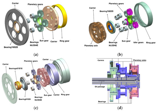
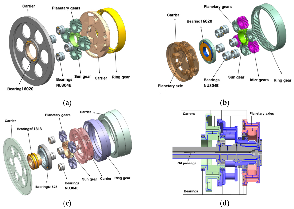
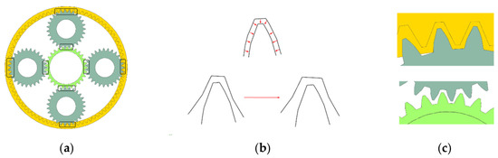
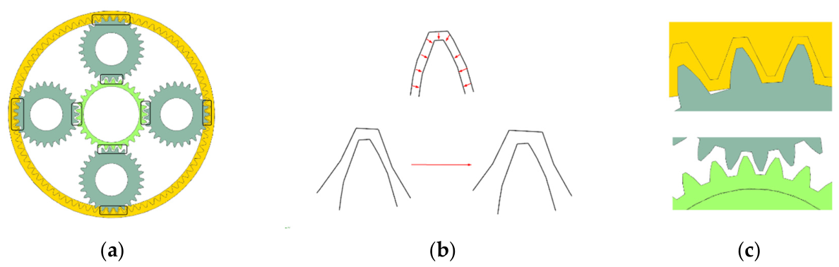
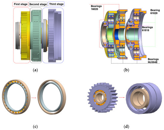
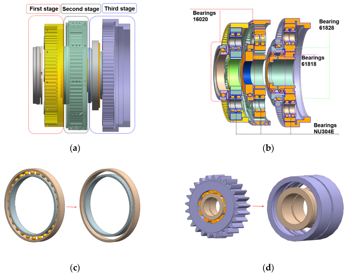
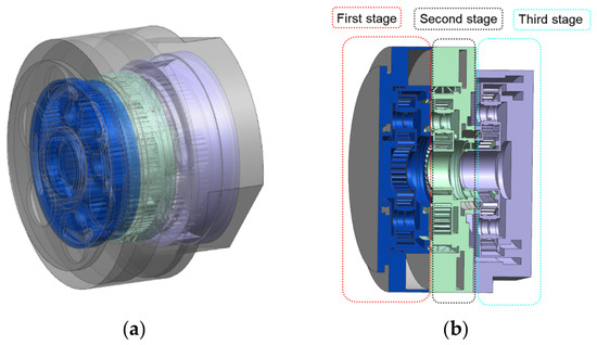
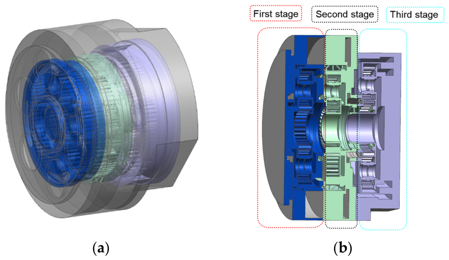
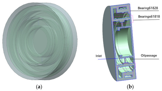
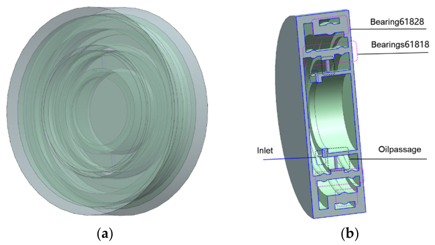
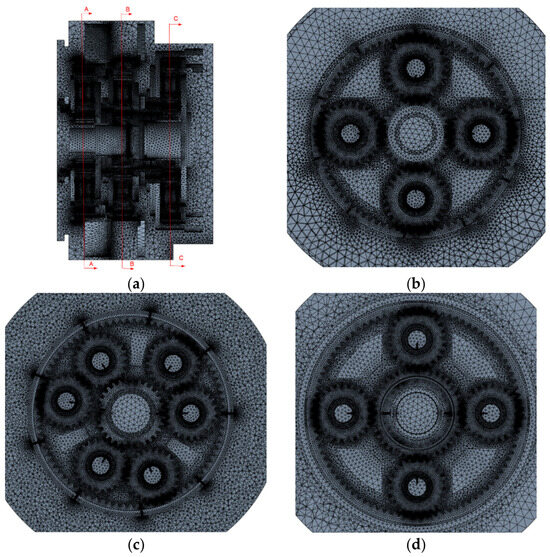
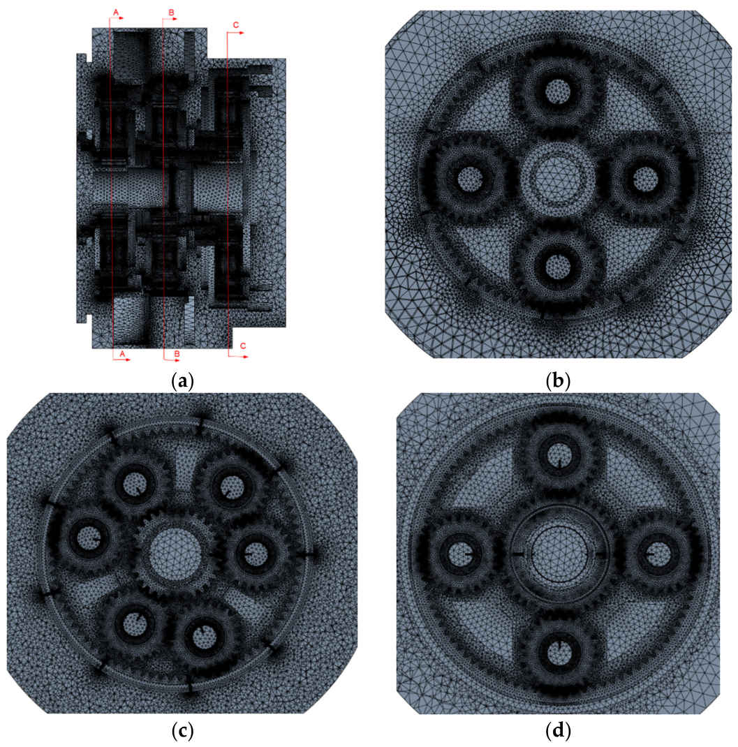
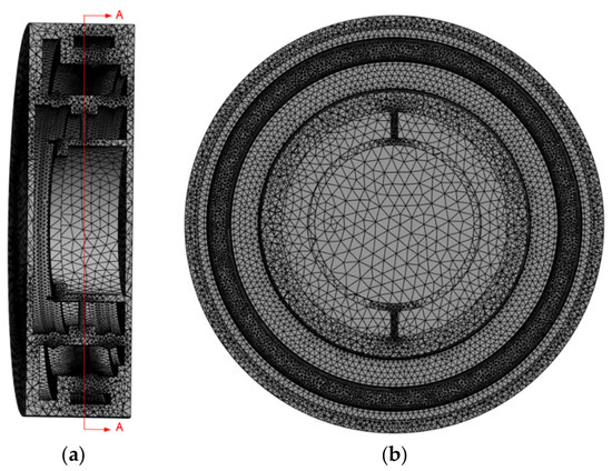
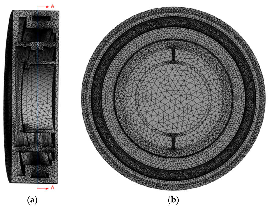
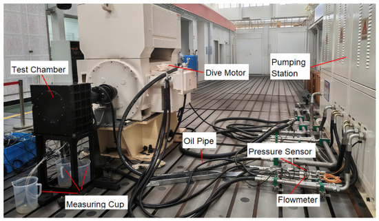
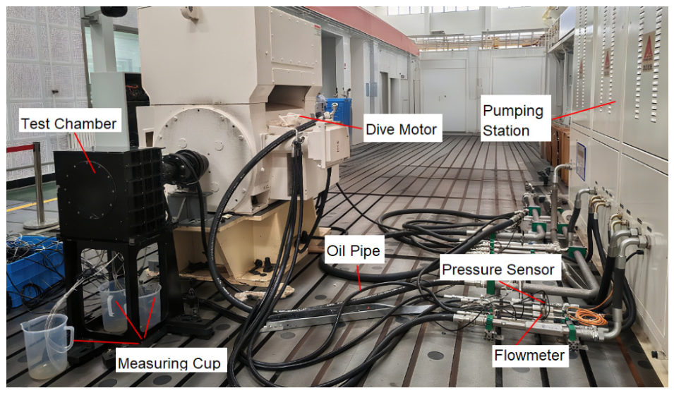
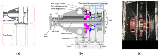
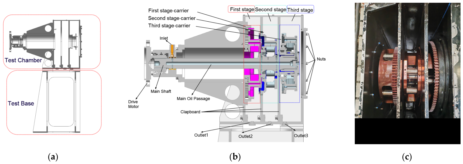
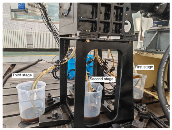
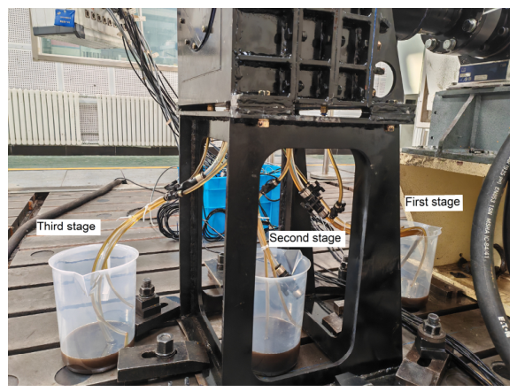
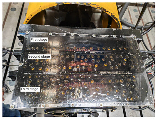
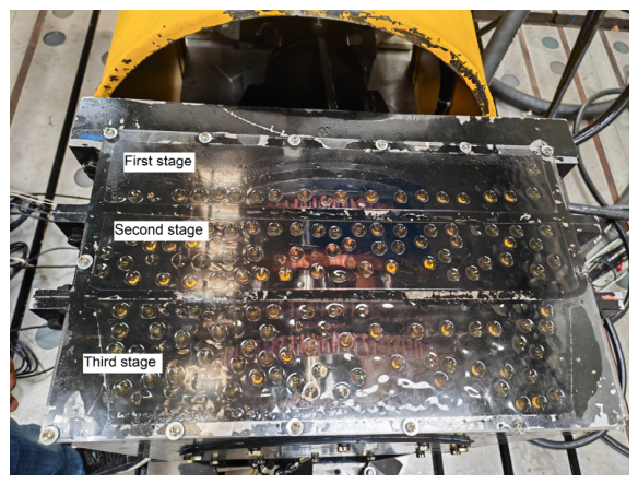
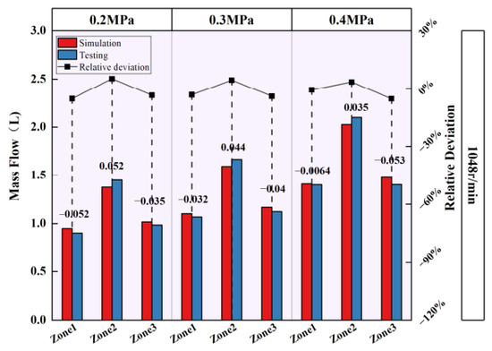
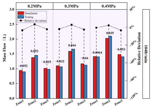
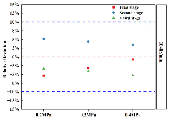
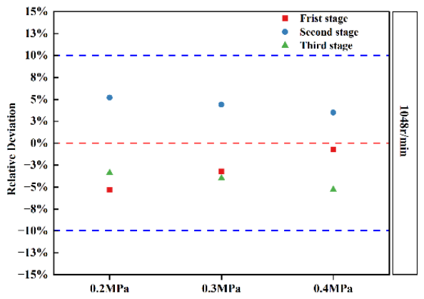

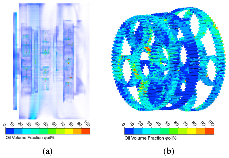
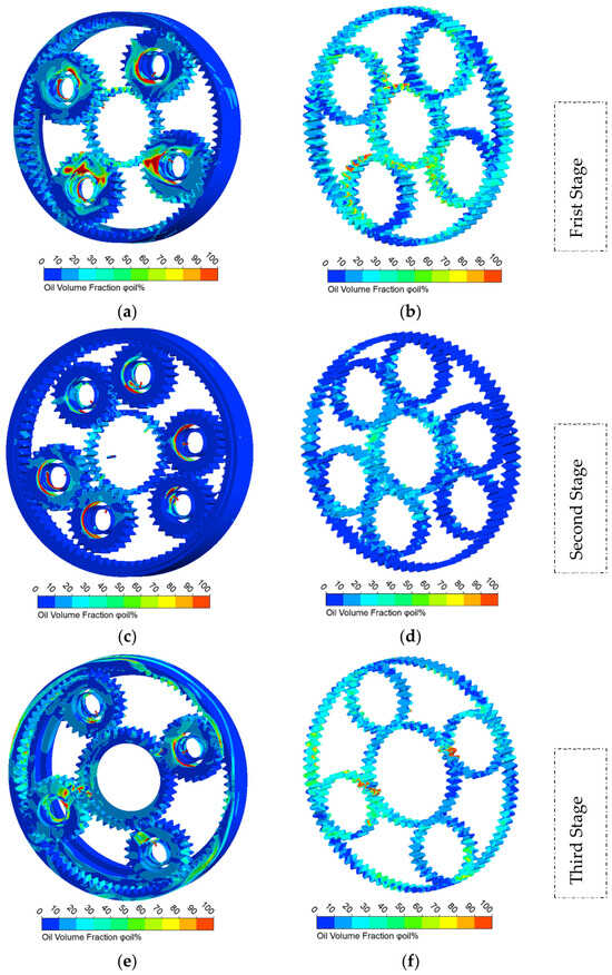
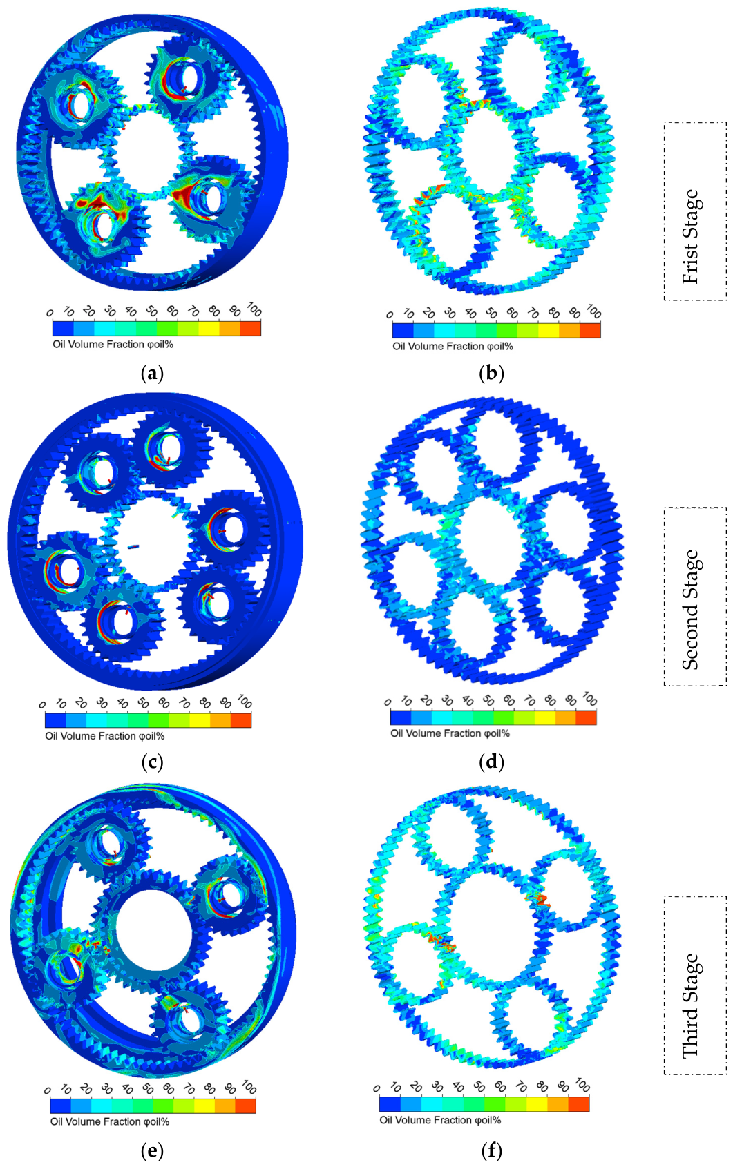
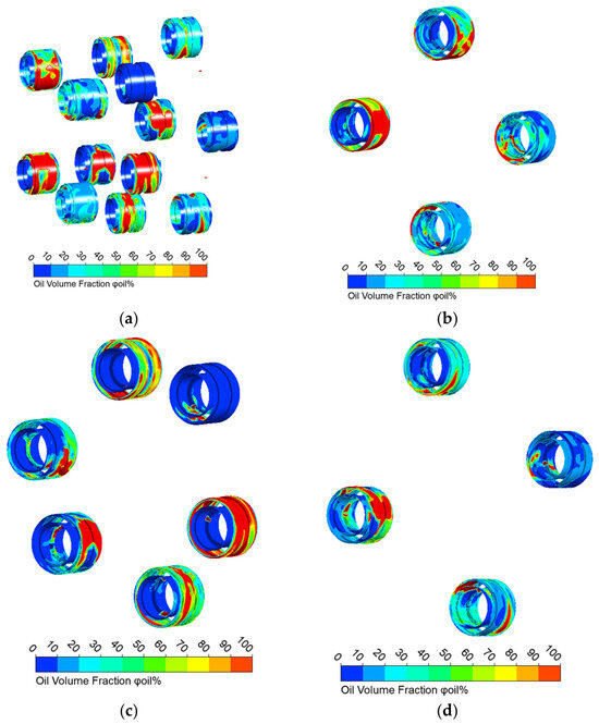
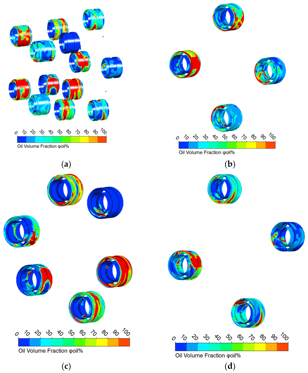
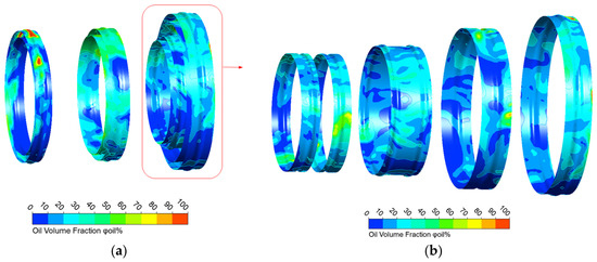
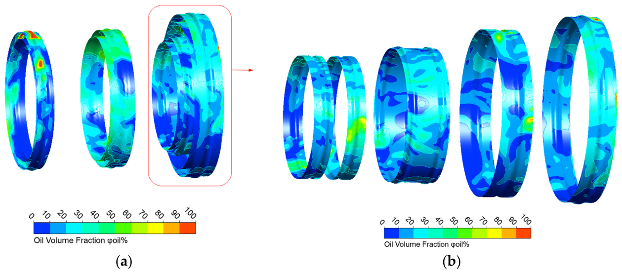
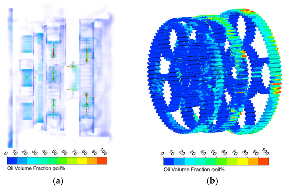
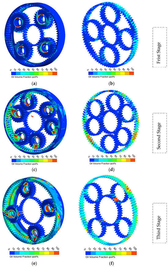
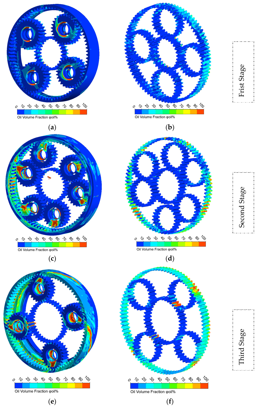
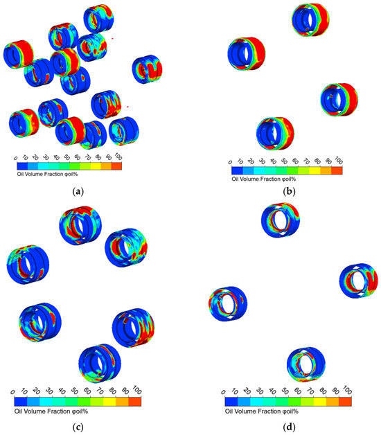
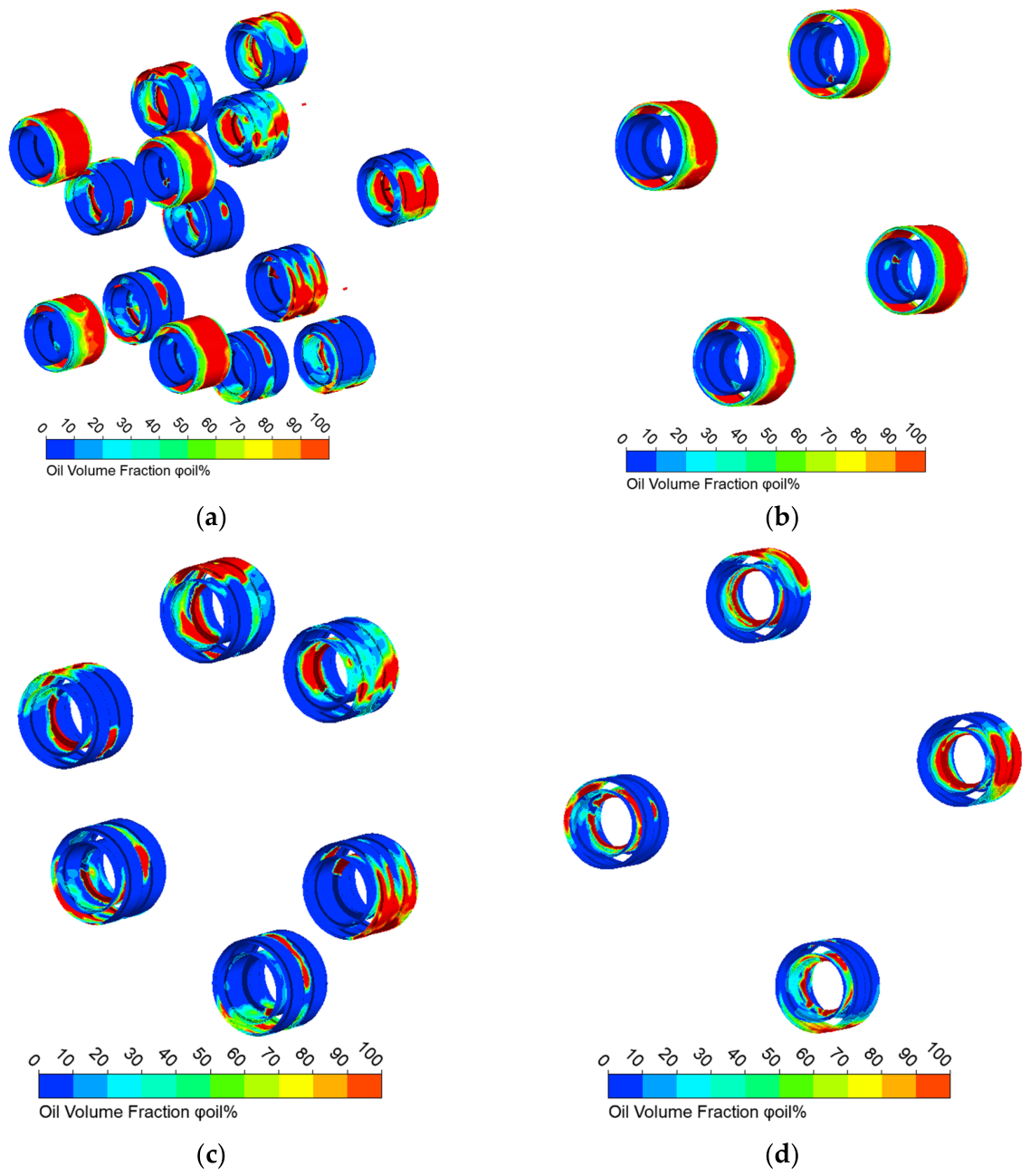
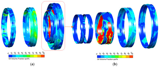
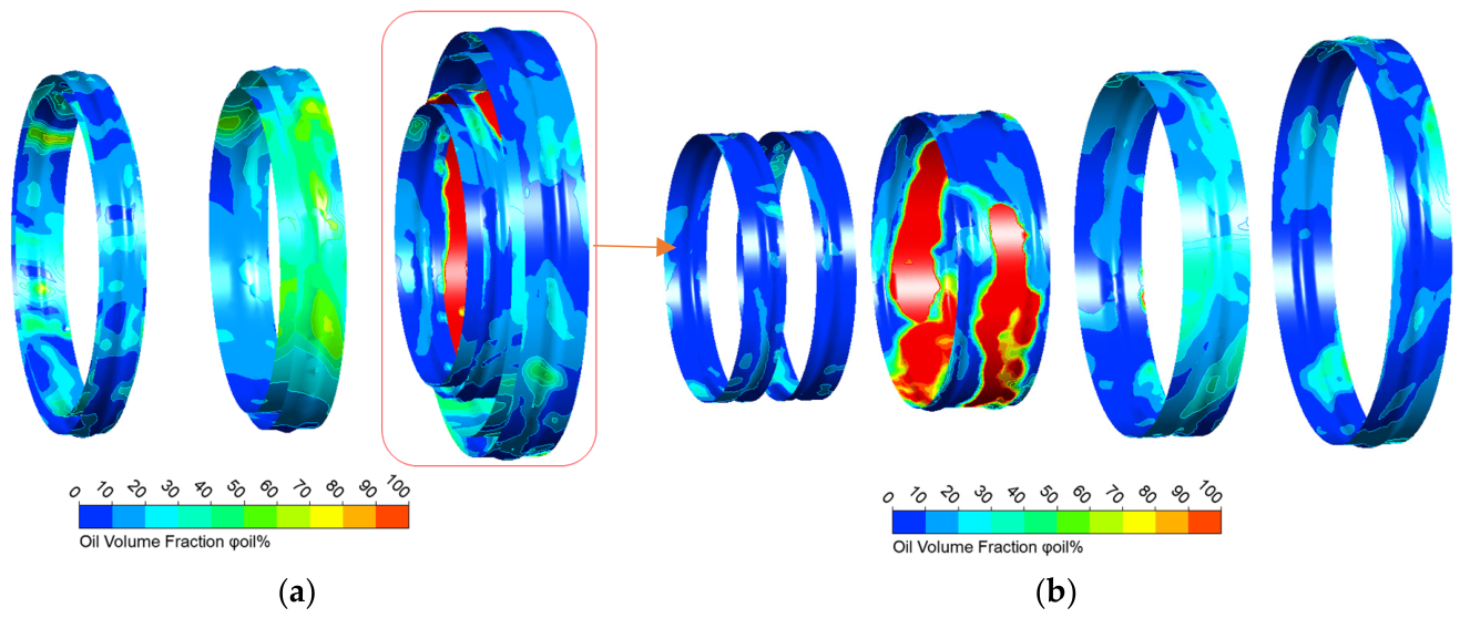
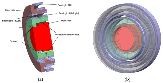
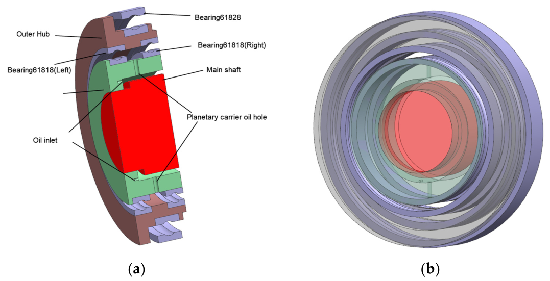
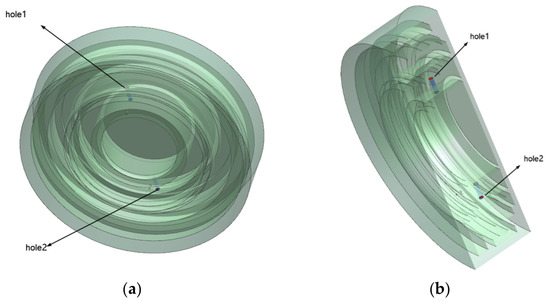
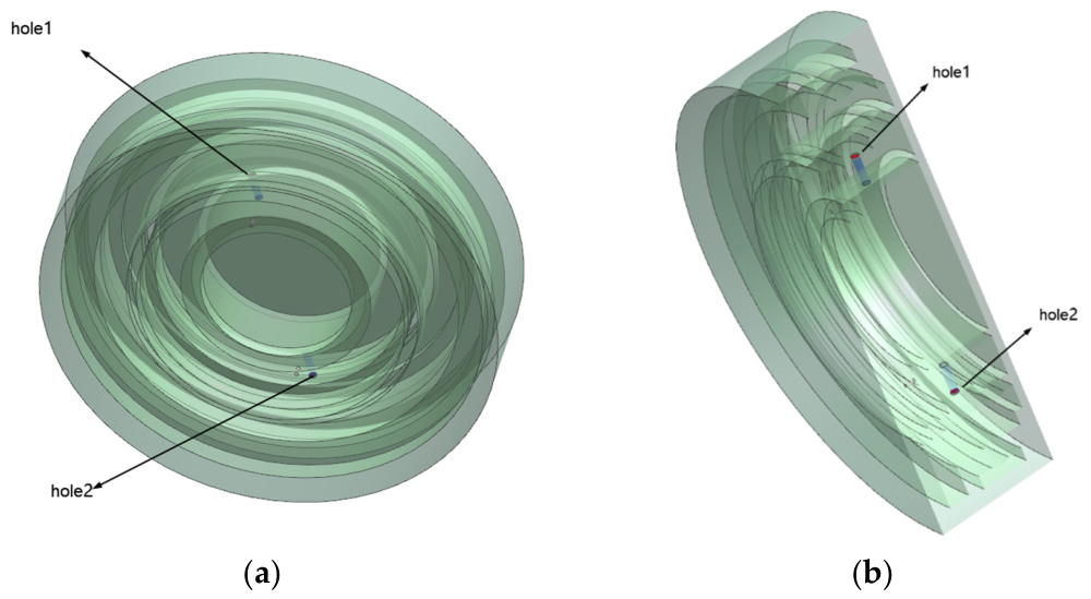
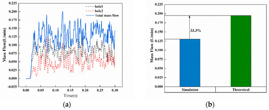
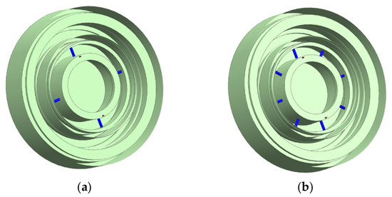
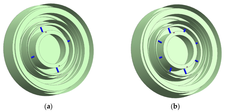
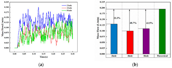
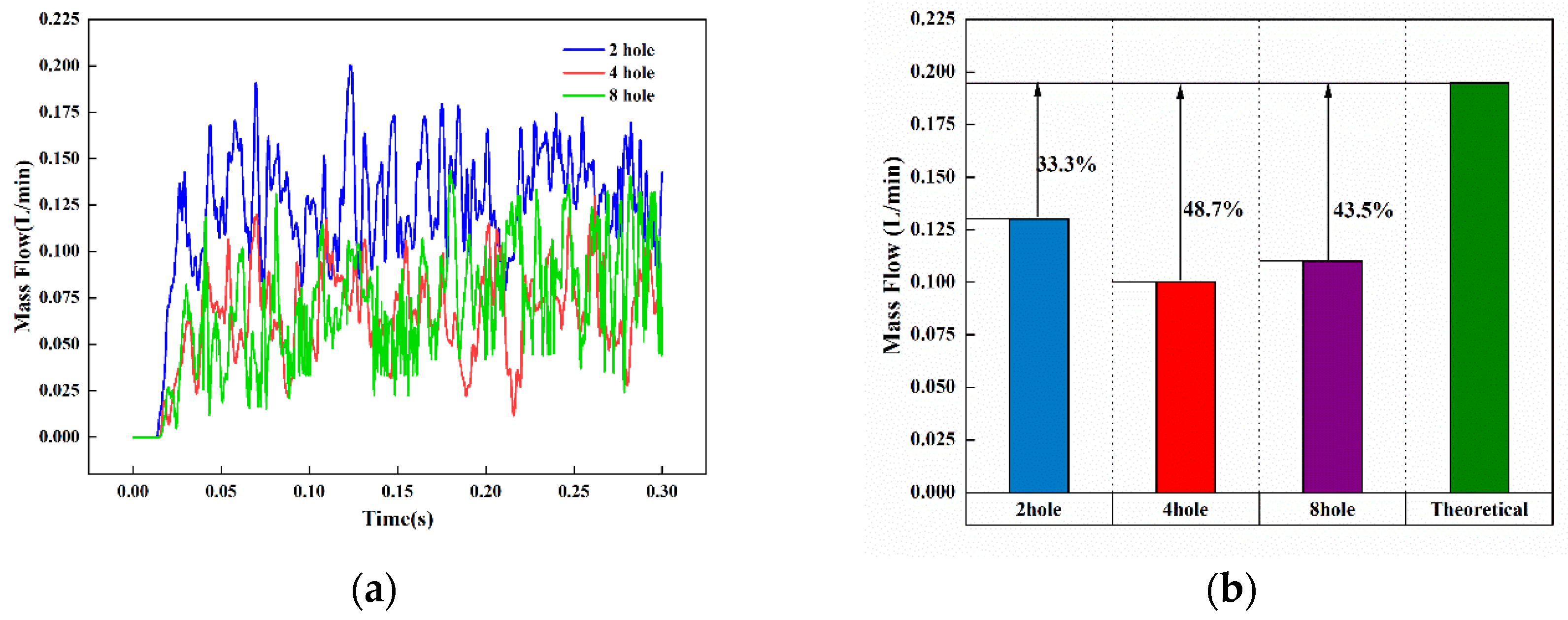
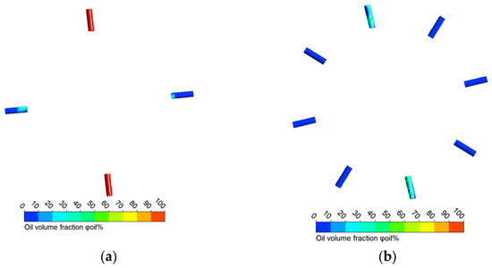
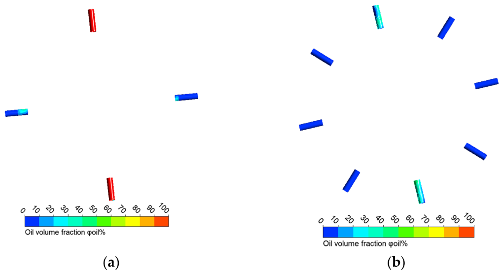
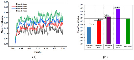
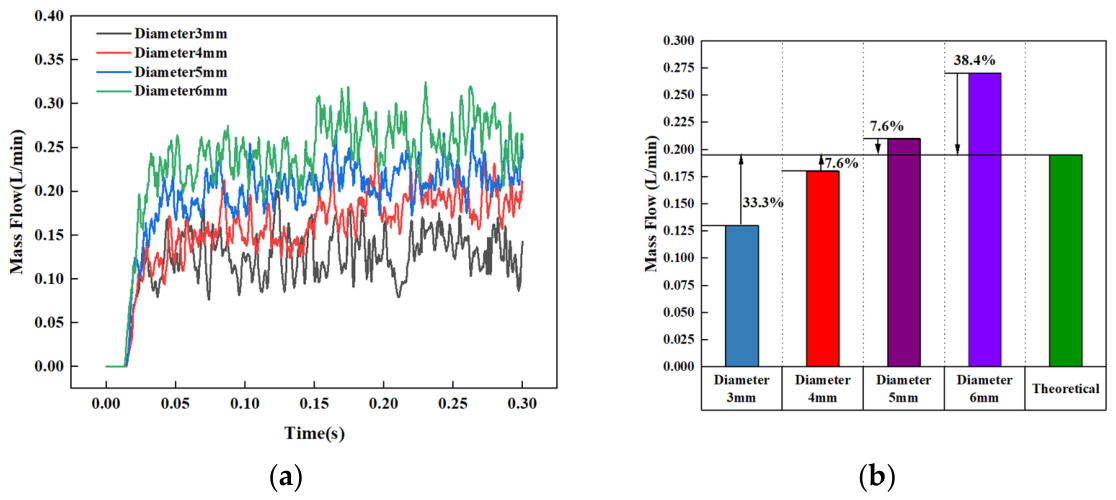
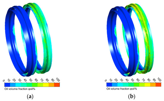
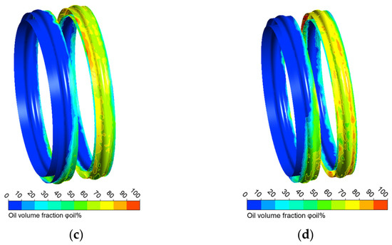
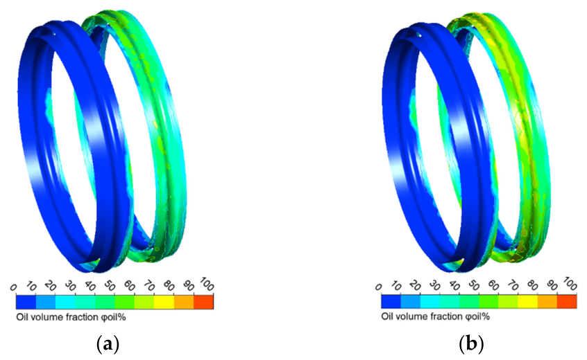
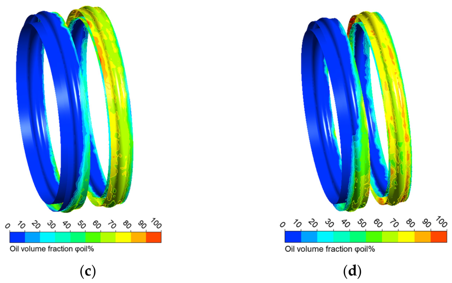
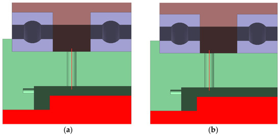
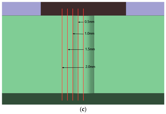
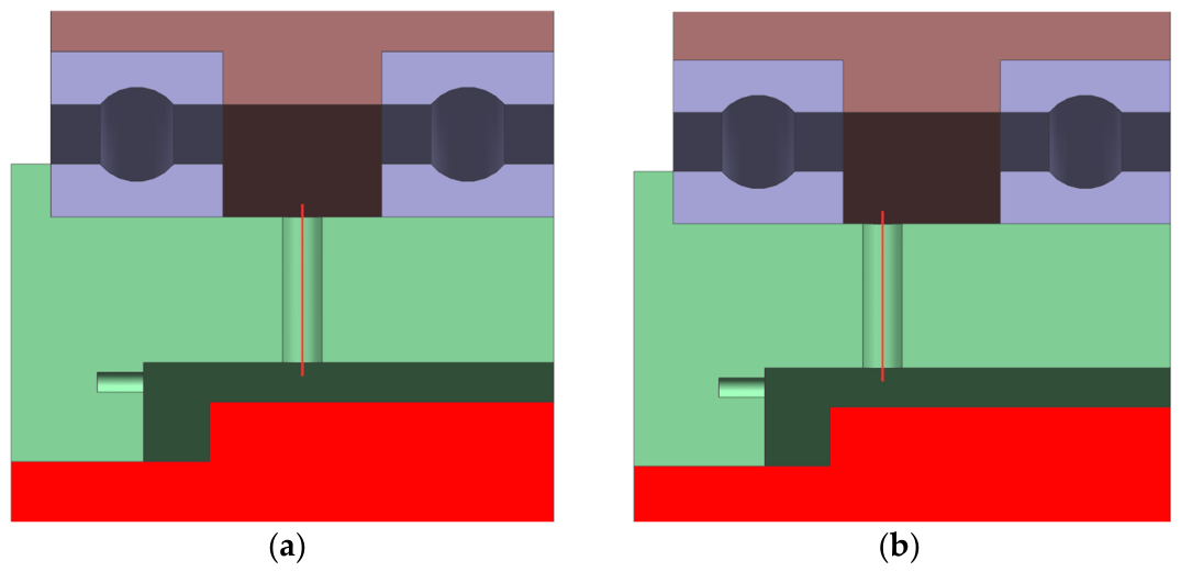
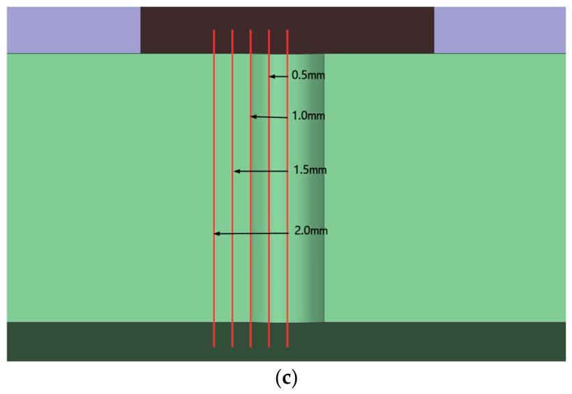
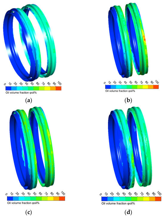
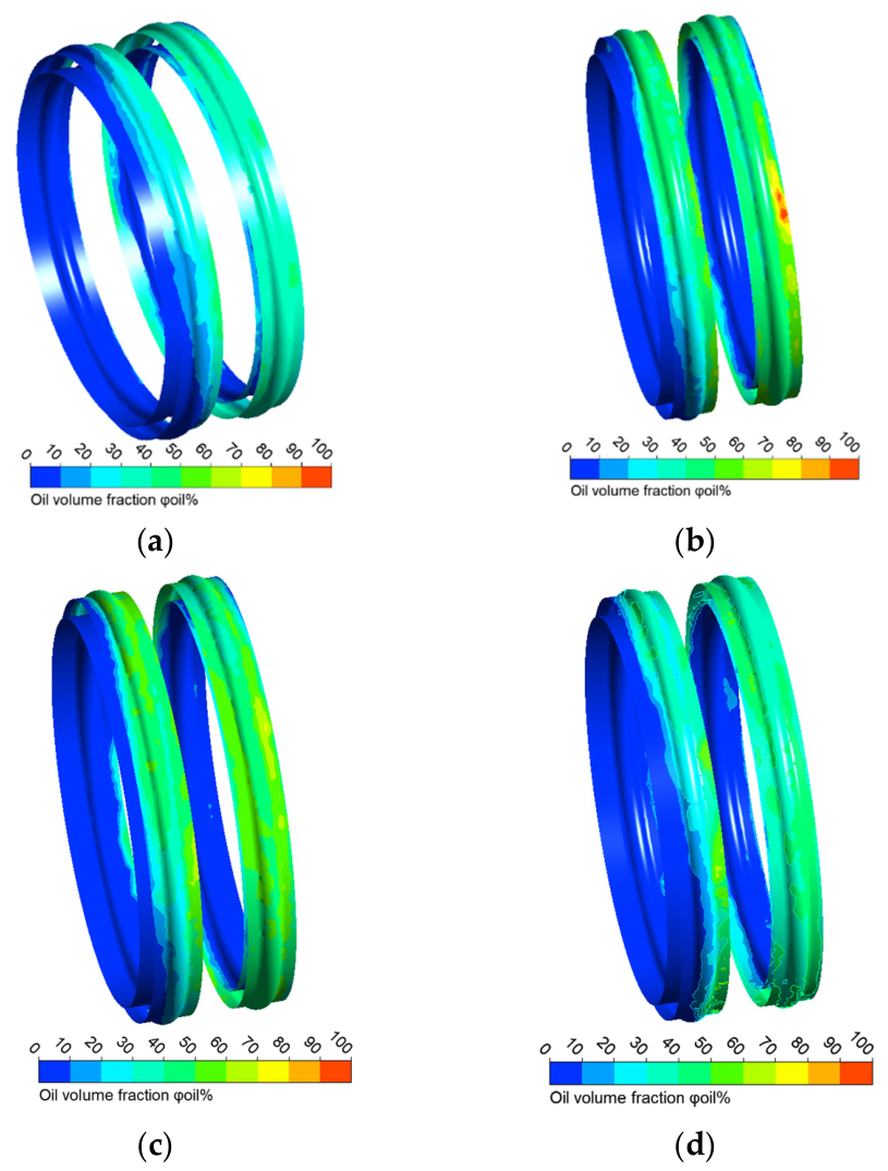
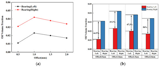
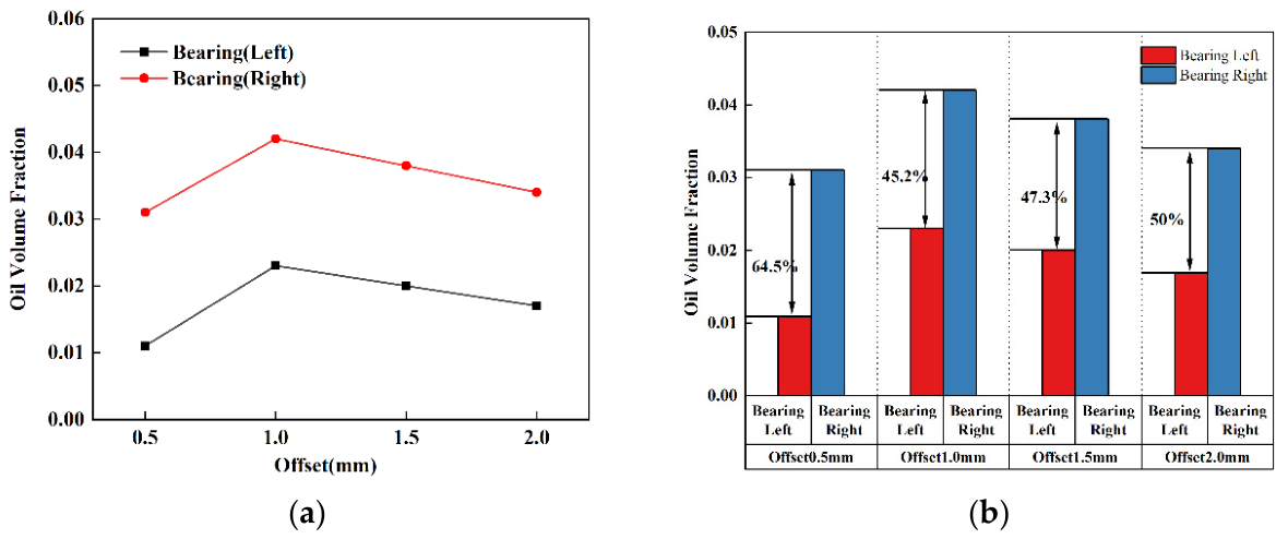
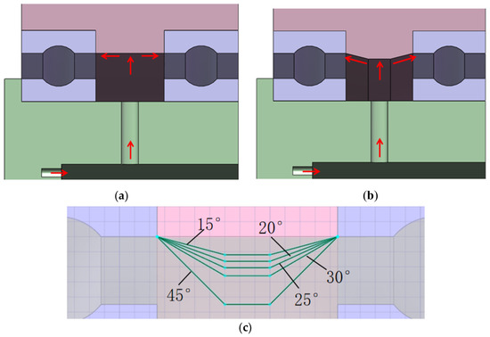
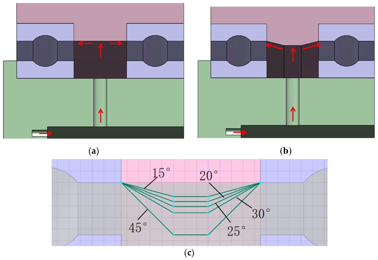
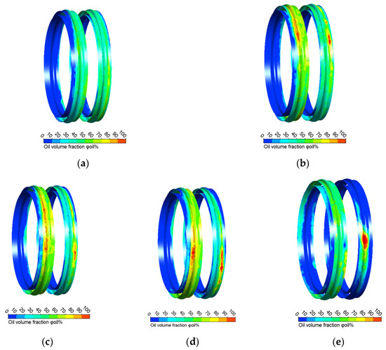
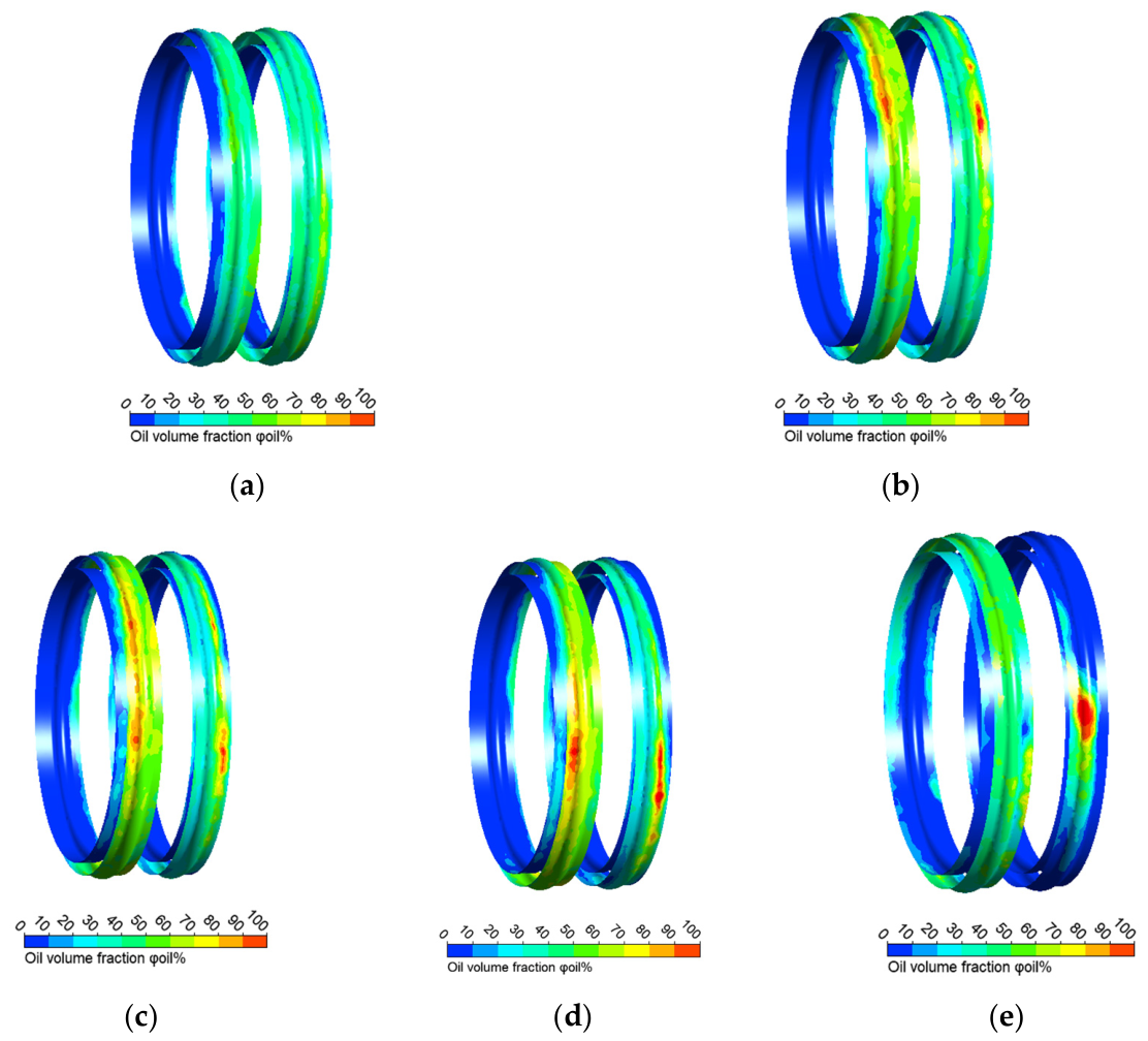
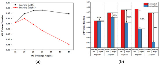
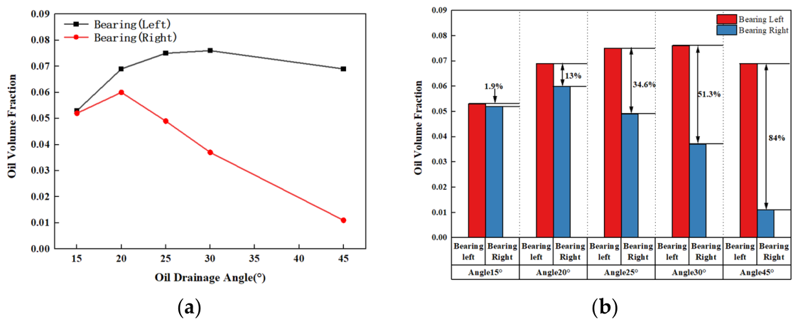

Disclaimer/Publisher’s Note: The statements, opinions and data contained in all publications are solely those of the individual author(s) and contributor(s) and not of MDPI and/or the editor(s). MDPI and/or the editor(s) disclaim responsibility for any injury to people or property resulting from any ideas, methods, instructions or products referred to in the content. |
© 2026 by the authors. Licensee MDPI, Basel, Switzerland. This article is an open access article distributed under the terms and conditions of the Creative Commons Attribution (CC BY) license.