


Abstract
Aircraft stands impose asymmetric spatial and procedural constraints that cannot be represented by geometric free space alone. This study proposes a Structured Operation Corridor for unmanned ground support equipment (SOC-UGSE), which converts existing stand markings, aircraft-side boundaries, and operating rules into machine-interpretable corridor constraints and corridor-specific actions. The framework distinguishes a detour-permitted Longitudinal Transfer Corridor (LTC-UGSE) from a no-detour Lateral Service-Approach Corridor (LSAC-UGSE), and maps object class, motion state, distance, corridor occupancy, and available clearance to Normal, Warning, or Stop responses. Standard vision, ranging, LiDAR, and temporal-processing modules are used only to instantiate these decision variables. On a controlled 1:10-scale platform, the implemented perception chain achieved an overall corridor-perception success of 83.9%, while frame-level agreement with rule-derived reference states reached 90.95%. Across 63 independent interaction sequences, sequence-level success was 95.2%, with no complete missed-stop event or prohibited boundary crossing. In a separate balanced comparison of 150 sequences, SOC-UGSE achieved the highest overall scenario-response compliance of 94.7%, outperforming distance-only stopping and corridor-free obstacle avoidance by reducing unnecessary stops and prohibited actions, respectively. These results support the structured-corridor rule-execution concept under controlled scaled-platform conditions, rather than full-scale operational safety or deployment readiness.
1. Introduction
Aircraft stands are among the most constrained and interaction-intensive areas of airport ground operations. Aircraft, ground support equipment (GSE), personnel, and service facilities operate in close proximity, so local vehicle motion is governed not only by free space but also by marked boundaries and operating procedures. ICAO A-SMGCS specifications emphasize continuous management of airport-surface traffic and operational boundaries [1], with corresponding implementation guidance from EUROCONTROL [2]. In near-aircraft areas, IATA AHM 913 defines ground-handling requirements [3], while MH5001-2021 specifies relevant aircraft-side safety and operating constraints [4].
As unmanned ground equipment (UGSE) is introduced into these environments, stand-side rules must be converted into machine-interpretable constraints. Existing studies have examined aircraft-stand management and operational efficiency [5,6], GSE automation and control [7,8,9], visual monitoring of personnel and vehicles [10,11,12], and related apron conflict assessment, aircraft-motion behavior analysis, trajectory anomaly analysis, and aircraft-scene understanding [13,14,15,16].
Safe-corridor construction and constrained trajectory planning provide useful geometric representations for navigation in restricted environments [17,18,19,20], while vision-based lane and boundary detection can extract structured regions from images [21,22,23]. Near-aircraft operation nevertheless differs from general road or free-space navigation because avoidance permissions are asymmetric: constrained detouring away from the aircraft may be permitted in one region but prohibited in a more restricted service-approach region. Geometric free space alone is therefore insufficient to represent stand-side UGSE operating constraints.
Multi-source perception provides the measurements needed to instantiate these constraints. Visual–LiDAR–inertial methods support localization and state estimation [24,25,26], camera–LiDAR fusion provides complementary geometric observations [27,28,29], safety-oriented models convert geometric observations into interpretable decision variables [30,31,32], and camera calibration supports physical-space projection [33,34,35]. Object detection and tracking further provide object class and motion information [36,37,38,39,40,41,42]. For vehicle-side decision-making, these outputs must be converted into structured variables tied to corridor boundaries, occupancy relationships, and operating rules.
To address this gap, this study develops a Structured Operation Corridor for Unmanned Ground Support Equipment (SOC-UGSE) and a corridor-aware rule-based safety-state framework for near-aircraft operation. SOC-UGSE converts stand markings, aircraft-side boundaries, and operating rules into machine-interpretable spatial and behavioral constraints, distinguishing the Longitudinal Transfer Corridor for Unmanned Ground Support Equipment (LTC-UGSE), where constrained outward detouring may be permitted, from the Lateral Service-Approach Corridor for Unmanned Ground Support Equipment (LSAC-UGSE), where lateral detouring is prohibited. Multi-source perception supplies corridor geometry, object class, distance, motion state, occupancy, and clearance, which are mapped to Normal, Warning, and Stop states and corridor-specific actions. The overall operational workflow of SOC-UGSE, linking UGSE task assignment with structured-corridor selection and corridor-constrained movement within the aircraft stand, is illustrated in Figure 1.
Figure 1.
Schematic workflow of UGSE operations under the SOC-UGSE.
The main contributions of this study are as follows:
- A structured-corridor representation for near-aircraft UGSE operation is established. SOC-UGSE formalizes stand markings, aircraft-side hard boundaries, nominal travel references, and corridor-specific operating permissions as explicit spatial constraints. The distinction between the LTC-UGSE and LSAC-UGSE enables asymmetric detour permissions specific to aircraft-stand operation to be represented beyond conventional geometric free space.
- A corridor-aware safety-event and rule-mapping mechanism is formulated. Object class, motion state, distance, corridor occupancy, and available clearance are mapped to Normal, Warning, and Stop states and to corridor-specific permissible actions. Conservative fallback is applied when critical perception, motion, or clearance information is invalid or uncertain.
- The framework is evaluated at perception, decision, and closed-loop execution levels. Experiments include corridor-perception stress tests, object-detection and ranging evaluation, frame- and sequence-level rule-execution analysis, corridor-specific detouring, braking, and stopping trials, and a balanced 150-sequence comparison with distance-only stopping and obstacle avoidance without corridor constraints.
Standard HSV processing, ground-plane homography, lightweight YOLO detection, monocular ranging, LiDAR gating, and exponential moving average (EMA) smoothing are implementation components used to instantiate the required decision variables rather than independent methodological contributions. Validation is limited to low-speed operation on a controlled 1:10-scale platform; full-scale dynamics, real-apron environmental variability, operational authorization, independent safety validation, and certification remain outside the validated scope.
2. Related Work
2.1. UGSE at Aircraft Stands and Near-Aircraft Operational Safety
Studies of aircraft-stand operations have mainly addressed stand management, ground-handling simulation, GSE scheduling, and automated ground operations [5,6,7,8,9]. Related work has examined ground-staff behavior, turnaround monitoring, vehicle states, stand conflicts, and aircraft-scene understanding [10,11,12,13,14,15,16]. Together, these studies provide an important basis for airport-surface automation and monitoring.
Their outputs are nevertheless usually expressed as operational states, detected objects, or trajectories rather than vehicle-side constraints that directly determine whether UGSE should continue, decelerate, detour, or stop. Near-aircraft autonomy therefore requires stand markings and operating procedures to be translated into explicit spatial and behavioral constraints.
2.2. Structured Navigation and Corridor Representation
Safe-corridor construction, constrained trajectory planning, and visual boundary extraction provide complementary tools for navigation in restricted environments [17,18,19,20,21,22,23]. Linear and relative safe-corridor methods represent locally feasible space [17,18], cooperative planning and constrained optimization incorporate geometric and interaction constraints [19,20], and vision-based lane-detection methods support structured boundary extraction [21,22,23].
These methods are primarily designed for general road or free-space navigation. Aircraft stands impose additional asymmetric constraints: motion toward the aircraft side may be prohibited, and permissible avoidance behavior changes with the operating corridor. A stand-side corridor representation must therefore encode both navigable geometry and corridor-specific operating permissions.
2.3. Multi-Source Perception and Safety-State Inputs
Multi-source state estimation and camera–LiDAR fusion have been widely studied for localization, ego-motion estimation, and environmental perception [24,25,26,27,28,29]. Safety-oriented models further convert geometric observations into interpretable proximity or decision variables [30,31,32], while camera calibration, object detection, and multi-object tracking support physical-space projection, object recognition, and temporal motion estimation [33,34,35,36,37,38,39,40,41,42].
For stand-side UGSE, these perception outputs must additionally be related to aircraft-side boundaries and corridor occupancy. Relevant decision variables therefore include not only object class and distance but also motion state, occupancy relationship, and available rule-compliant clearance.
2.4. Safety-State Classification and Corridor-Specific Avoidance
Airport-surface conflict detection and collaborative trajectory planning have considered interactions among aircraft and ground vehicles [43,44]. These studies, however, primarily address conflict resolution or trajectory generation and do not explicitly encode different permissible actions for distinct near-aircraft operating corridors.
Accordingly, this study uses rule-based safety-state classification rather than probabilistic risk estimation. SOC-UGSE distinguishes the detour-permitted LTC-UGSE from the no-detour LSAC-UGSE and maps object class, motion state, distance, corridor occupancy, and available clearance to the Normal, Warning, and Stop states and their corridor-specific actions. Table 1 summarizes the main related research directions and highlights the positioning of the present SOC-UGSE framework relative to existing studies.
Table 1.
Summary of related studies and positioning of this work.
3. Problem Formulation and Overall System Framework
To represent the combined geometric and procedural constraints of near-aircraft operation, the proposed framework maps multimodal sensor observations to structured decision variables and then to corridor-specific control actions, as shown in Figure 2. The processing chain is organized into sensor, perception, and decision layers.
Figure 2.
Overall system architecture.
The sensor layer acquires multimodal environmental observations and ego-vehicle states. The RGB-D camera and elevated RGB camera provide visual observations for the Longitudinal Transfer Corridor for UGSE (LTC-UGSE) and Lateral Service-Approach Corridor for UGSE (LSAC-UGSE), respectively. LiDAR supplies short-range geometric observations and corridor-occupancy confirmation, while IMU and wheel odometry provide the ego-motion reference used for subsequent compensation.
The perception layer converts heterogeneous sensor data into structured safety-state inputs. Corridor perception generates geometric boundaries and core occupancy regions from stand markings; object detection and ranging provide object class and relative position; and motion estimation classifies targets as static, dynamic, or uncertain after local ego-motion compensation.
The decision layer maps these structured inputs to executable actions. Object class, motion state, corridor occupancy, and class-specific distance thresholds determine Level I Normal, Level II Warning, or Level III Stop, after which the LTC-UGSE or LSAC-UGSE rule set selects the permissible control response. This forms the perception–decision–control loop used in the experiments.
4. Structured Operational-Corridor and Rule Modeling
4.1. Definitions of the LTC-UGSE and LSAC-UGSE Structured Corridors
To transform complex stand-side near-aircraft operating rules into computable control constraints for UGSE, this study constructs an SOC-UGSE model in the local stand coordinate frame . In this coordinate frame, the -axis is aligned with the main travel direction of the corridor, while the -axis denotes the lateral offset direction. According to the relative distance between the operating area and the aircraft, the corridor is divided into the LTC-UGSE and the LSAC-UGSE.
- (1)
- LTC-UGSE
The LTC-UGSE is the primary longitudinal transfer region within the aircraft stand. Relative to the near-aircraft service-approach region, it provides greater lateral clearance and therefore permits a constrained detour only toward the side away from the aircraft when a static obstacle satisfies the applicable rule conditions. Intrusion toward the aircraft-side boundary remains prohibited.
Let the aircraft-side hard boundary, the corridor center reference line, and the outward detour extension boundary be denoted by , , and , respectively. Let the signed boundary functions and describe the positional relationship of a point with respect to the two boundary types. The LTC-UGSE corridor region is formally defined as:
where denotes the longitudinal transfer corridor region; and constrain the aircraft-side hard boundary and the detour-allowable boundary on the side away from the aircraft, respectively; and represents the range of the current longitudinal transfer segment.
Under obstacle-free conditions, the vehicle travels stably within the center constraint band , which is formed along the center reference line :
where denotes the allowable lateral deviation.
The schematic structure of the LTC-UGSE is shown in Figure 3, and the physical and rule-based semantics of the key corridor reference lines are listed in Table 2.
Figure 3.
Schematic structure of the LTC-UGSE.
Table 2.
Definitions of boundary and reference lines in the LTC-UGSE.
- (2)
- LSAC-UGSE
The LSAC-UGSE is the more constrained corridor used as the vehicle approaches a near-aircraft service position. Because lateral maneuvering is restricted near the aircraft, the adopted corridor rule prohibits detouring: the vehicle follows the service-approach centerline, decelerates when required, and stops when the applicable condition is triggered.
Let the non-crossable hard boundaries on the left and right sides of the LSAC-UGSE be denoted by and , respectively, and let the terminal stopping reference line be denoted by the Finish Line of LSAC-UGSE (FL-LSAC). The lateral service-approach corridor region is defined as:
where denotes the lateral service-approach corridor region; and constrain the non-crossable boundaries on the two sides of the corridor, respectively; and represents the range of the near-aircraft travel segment.
Because this corridor follows the no-detouring straight-line travel rule, the nominal travel band is defined as:
where is the center constraint line, and denotes the allowable lateral deviation.
The schematic structure of the LSAC-UGSE is shown in Figure 4, and the related geometric boundary definitions are provided in Table 3.
Figure 4.
Schematic structure of the LSAC-UGSE.
Table 3.
Definitions of boundary and reference lines in the LSAC-UGSE.
4.2. Safety-Relevant Object Classification and Corridor-Occupancy Modeling
UGSE avoidance rules depend on both detected object class and the object’s topological relationship with the structured corridor. The four classes are not assigned probabilistic risk scores. Instead, operational attributes, motion uncertainty, and potential consequences are used to select conservative rule conditions, as summarized in Table 4.
Table 4.
Safety-relevant object classification and applicable rules.
The occupancy relationship between the object and the corridor is formally modeled by spatial set intersections as follows:
where denotes the occupancy state of safety-relevant object ; denotes its spatial envelope; denotes the current nominal corridor region; denotes the core occupancy region; and the empty set indicates no spatial intersection.
This topological relationship determination jointly considers the object envelope, the ego-vehicle safety envelope, and the corridor boundaries. Reducing the multidimensional geometry to the discrete occupancy state provides a reproducible rule input for standardized safety-event generation and subsequent decision-table lookup.
5. Multi-Source Perception of Stand Markings and Safety-Relevant Objects
5.1. Perception of SOC-UGSE at Aircraft Stands
SOC-UGSE perception uses existing stand markings to generate navigable regions, core occupancy areas, and hard/soft boundary constraints. The LTC-UGSE and LSAC-UGSE are then instantiated from these geometric references according to vehicle width and operating rules.
To reduce sensitivity to illumination, shadows, and ground reflections, ROI brightness is used to switch among three pre-calibrated HSV parameter sets for low, normal, and strong illumination/local reflection. This lightweight implementation supports SOC-UGSE instantiation on the current platform rather than introducing a new segmentation method. Equations (6)–(8) define the ROI brightness, switching rule, and HSV mask, with calibrated thresholds reported in Section 7.1.
- (1)
- LTC-UGSE perception process
For the LTC-UGSE (Figure 5), the brightness-selected HSV mask is processed using standard morphological operations, after which center points are fitted to the longitudinal reference marking. Ground-plane projection and geometry-based expansion then generate the core region, INB-LTC, and ODEL-LTC from the vehicle width, safety margins, and corridor rules.
Figure 5.
Process of stand-marking extraction and corridor-region generation for the LTC-UGSE. (a) Original image; (b–d) marking extraction and mask processing; (e,f) ROI filtering and center-point extraction; (g,h) geometric projection and corridor-region generation.
- (2)
- LSAC-UGSE perception process
For the LSAC-UGSE (Figure 6), connected-component filtering and ROI-based scanning are applied to the brightness-selected mask to extract the lateral guidance line and FL-LSAC. Standard camera calibration and ground-plane projection then generate the bilateral NCB-LSAC boundaries and the no-detour service-approach corridor.
Figure 6.
Process of stand-marking extraction and corridor-region generation for the LSAC-UGSE. (a) Original image; (b–d) marking extraction and mask processing; (e,f) ROI filtering and center-point extraction; (g,h) generation of the lateral near-aircraft corridor and finish-line constraint.
The extracted marking points are mapped to the local stand frame using the calibrated ground-plane homography in Equation (9), and the resulting reference line is expanded along its normal direction to form the corridor boundaries in Equation (10). These are standard geometric operations; the corridor-specific contribution lies in assigning the resulting boundaries different hard/soft constraints and operating permissions.
Detected-object footprints are intersected with the corridor polygons to obtain occupancy states. If the principal marking or FL-LSAC cannot be reconstructed reliably, or if the polygon is incomplete or unstable, that observation is rejected. In the no-detour LSAC-UGSE, the vehicle defaults to Stop-and-wait until a valid corridor is re-established.
5.2. Lightweight YOLO Detection for Safety-Relevant Objects
A lightweight YOLO detector identifies safety-relevant objects and outputs object class, confidence, and two-dimensional bounding boxes. Because object class selects downstream safety rules and distance thresholds, the detector is evaluated under small-object conditions, partial vehicle occlusion, and illumination variation in the stand-scene dataset.
YOLOv5s is used as the baseline for edge-oriented lightweight reconstruction. To reduce computation while retaining the P3, P4, and P5 detection scales required for low-profile obstacles, personnel, and GSE of different apparent sizes, the modified network combines a lightweight backbone with low-cost feature-fusion modules, as shown in Figure 7.
Figure 7.
Architecture of the improved YOLOv5s model.
The lightweight reconstruction contains two modifications. Backbone lightweighting: selected high-cost convolutional structures are replaced by ShuffleNetV2 modules to reduce edge-side computation while preserving multiscale feature extraction, as shown in Figure 8b. Neck redundancy reduction: conventional C3 modules in the multiscale feature-aggregation stage are replaced by C3Ghost modules, which reduce redundant computation through low-cost feature generation, as shown in Figure 8a.
Figure 8.
Structures of the improved modules: (a) C3Ghost module; (b) ShuffleNetV2 module.
5.3. Obstacle Ranging and Motion-State Estimation
YOLO detections are converted into the spatial variables required by the safety-state decision layer. Camera projection, LiDAR-sector processing, and temporal smoothing are implementation components; their role is to provide decision-valid distance, lateral offset, and motion state under the conservative validity rules defined below.
Figure 9 summarizes monocular ranging based on ground-plane geometric projection and size-prior fusion, using the detected ground-contact point to relate image observations to ground distance.
Figure 9.
Principle of monocular ranging based on geometric projection and size-prior fusion.
- (1)
- Visual ranging and size-prior fusion for small objects
For low-profile obstacles, the vertical pixel coordinate of the detection-box ground-contact point is first corrected to reduce reference-point jitter caused by pose variation:
where is the corrected vertical coordinate of the ground-contact point, is the lower-edge coordinate of the detection box, is the ground-contact correction coefficient, and is the detection-box height.
The geometric-projection depth is then fused with the size-prior depth to obtain the visual-depth estimate :
where is the fusion weight.
This fusion is used to reduce the sensitivity of small-object ranging to ground-contact-point jitter and apparent-scale variation.
- (2)
- Safety-oriented gated camera–LiDAR depth fusion for large objects
For large vehicle targets, visual ranging is susceptible to contour truncation, partial occlusion, and rapid apparent-scale variation at short range. The object bearing is therefore estimated from the center of the YOLO detection box, and valid points are extracted from the corresponding LiDAR angular sector. The LiDAR sector-based distance observation is calculated using the sector median:
where is the object azimuth sector; and denote the radial range and azimuth angle of the th LiDAR point, respectively; and and define the valid LiDAR range in the current scaled experiment. In the present narrow forward sector, this radial range is used as a line-of-sight approximation to the longitudinal decision distance; a full-scale implementation should explicitly transform LiDAR points into the vehicle frame before extracting the longitudinal component.
The median, rather than the single-point minimum, attenuates sparse reflections, isolated returns, and background points. Let be the number of valid candidate ranges in the sector and the true target distance. If more than half of the candidates lie within an interval of radius around , then
Thus, fewer than half of the candidate points may be arbitrary outliers without moving the median outside the bounded inlier interval; equivalently, the median has an asymptotic breakdown point of 50% [45]. This property bounds the influence of sparse contamination under the stated inlier condition, but does not imply rejection of all measurement noise.
To prevent invalid observations from entering the safety-state decision process, validity indicators are defined for the camera and LiDAR branches. Camera-branch validity is given by
where is the camera validity indicator, is the detection confidence, is its threshold, is the ground-contact point, is the valid ground-contact region, and and define the valid camera-ranging interval.
LiDAR-branch validity is similarly defined as
where is the LiDAR validity indicator, is the number of valid points in the object sector, is the minimum valid-point threshold ( in this study), and and define the valid LiDAR-ranging interval.
A branch is excluded from fusion when it has insufficient valid points or its robust distance estimate lies outside the effective range.
Before fusion, camera projection and LiDAR-sector processing convert the raw measurements into direct scalar observations of the same decision-distance variable. Let denote the true distance at frame . The fusion-layer observation model is
Under the conventional assumption of two independent zero-mean Gaussian measurements and without an informative dynamic prior, the minimum-variance linear unbiased estimate is given by the following inverse-variance weighted fusion; this can also be viewed as a static special case of Kalman-type measurement fusion [46]:
where and are the measurement-error variances. The estimate satisfies
This estimator optimizes a symmetric squared-error criterion but does not guarantee that the estimate is no greater than the nearer valid observation. For near-aircraft braking, distance overestimation can delay braking, whereas underestimation generally produces an earlier, more conservative response. To make this asymmetry explicit, the following loss is introduced as a safety-oriented design criterion:
where . Equation (20) expresses the safety preference rather than defining an estimator to be optimized directly. The implemented fusion rule in (21) instead enforces a deterministic one-sided conservative distance constraint; no claim of minimum mean-square error or Bayesian optimality is made.
After validity gating, and are combined into the decision-valid depth using
where and denote branch validity, and denotes the absence of a valid distance output. If both branches are invalid, the decision layer issues a conservative stop or wait command rather than interpreting zero as a valid distance.
Because branch activation is class dependent, the camera estimate is the primary observation for small targets, whereas the LiDAR constraint is additionally applied to large vehicle targets.
For the dual-valid case, let and . The fused positive overestimation error then satisfies
Hence, if at least one valid sensor does not overestimate the true distance, the fused distance also does not overestimate it. The rule may inherit a negative bias and cause earlier deceleration or stopping; this is the accepted conservative cost of the safety-oriented design.
EKF and UKF are appropriate when nonlinear states and covariances are recursively propagated through a validated transition model [46,47]. At the present fusion interface, however, the camera and LiDAR branches have already been reduced to scalar distance observations, and no common object-specific transition model has been validated for heterogeneous personnel, vehicles, and static obstacles. A recursive filter would therefore introduce dynamic-model assumptions not supported by the current dataset without adding a nonlinear measurement-update advantage at this interface. Particle filtering can represent non-Gaussian or multimodal posteriors, but likewise requires validated transition and likelihood models together with particle-number and resampling choices [48]. These stochastic filters remain relevant for future continuous-target-tracking extensions.
- (3)
- Temporal filtering and motion-state estimation
EMA is used only as a standard temporal smoother for motion-state estimation, as summarized in Equation (25). To avoid masking a newly observed closer target, the distance supplied to safety-state classification and braking follows the conservative rule in Equation (26). The smoothing factor is treated as a calibrated implementation setting rather than a methodological contribution.
Wheel-speed odometry and IMU data are used to compensate for short-term UGSE motion. Let be the compensated cumulative target displacement over consecutive frames. A target is classified as static when and its occupancy state remains stable; it is classified as dynamic or uncertain when , a corridor-entry trend is detected, tracking is lost, or the motion estimate is unreliable. For ground staff, static status is used only as a temporary decision condition in the controlled laboratory bypass test; it is not treated as operational permission to pass personnel. The static condition must remain valid before and throughout the laboratory maneuver; any detected change immediately cancels the maneuver and triggers stopping and waiting. A new laboratory bypass attempt can be considered only after a renewed -frame static confirmation and an updated clearance check. For full-scale airport deployment, detection of ground staff defaults to Stop unless a separately validated and airport-operator-approved personnel-passage procedure is established. Repeated tests on the scaled platform yielded and m.
The system finally outputs the target forward distance , lateral offset , object category , motion state , and occupancy state relative to the UGSE. These variables are projected into the SOC-UGSE local frame and used for subsequent safety-state classification and corridor-specific action selection.
6. Rule-Based Safety-State Classification and Corridor-Specific Avoidance
6.1. Safety-Event Modeling and Decision-Variable Definition
The decision layer is decoupled from raw images, point clouds, and low-level pose data by receiving standardized safety events from the perception layer. For each detected object, the safety-event vector is defined as:
where and denote object class and motion attribute, respectively; , , , and describe the object–corridor spatial relationship; and and are the class-specific warning and stopping thresholds derived below.
For object class , the stopping threshold is calculated from the maximum test speed, total system response time, constant-deceleration braking distance, class-specific ranging uncertainty, and a conservative class margin:
where is the declared maximum test speed; is the end-to-end perception–decision–control response time; is the conservative braking deceleration magnitude; is the ranging uncertainty for class ; and is the class-specific safety margin.
The warning threshold adds a fixed observation interval before the stopping threshold:
For the current 1:10-scale platform implementation, the declared calculation settings are = 0.50 m/s, = 0.20 s, = 0.50 m/s2, and = 1.00 s. The class-specific values are 0.02, 0.02, 0.06, and 0.06 m, and values are 0.20, 0.30, 0.30, and 0.40 m, for traffic cones, ground staff, UGSE, and manned GSE, respectively. Equation (28) gives 0.57, 0.67, 0.71, and 0.81 m; conservative upward rounding to the next 0.05 m increment yields the implemented values of 0.60, 0.70, 0.75, and 0.85 m. Using these conservatively rounded stopping thresholds in Equation (29) gives the implemented values of 1.10, 1.20, 1.25, and 1.35 m. These are declared control settings for this scaled platform rather than full-scale UGSE parameters; deployment requires remeasurement of speed, response time, braking deceleration, ranging uncertainty, and safety margins.
Equation (28) defines a conservative longitudinal operating condition for the current scaled implementation. Continued motion is permitted only when the available clearance remains consistent with the response distance, braking distance, ranging uncertainty, and prescribed safety margin. For LTC-UGSE detouring, the aircraft-side requirement is expressed by the sufficient lateral-clearance condition , where the left-hand term is the minimum planned clearance to INB-LTC, the three error terms bound tracking, corridor-reconstruction, and localization errors, and the final term is the prescribed lateral margin. Detouring is permitted only while this sufficient condition is satisfied; otherwise, Stop is enforced. It is a bounded operating criterion for the present proof-of-concept, not a formal full-scale safety guarantee or certification claim.
These variables reduce high-dimensional perception outputs to explicit, reproducible inputs for the rule-based decision logic.
Here, is discretized as outside, buffer intrusion, or core occupancy, while is static or dynamic; an uncertain motion estimate is handled conservatively as dynamic. These inputs allow direct lookup by class, distance, occupancy, corridor type, and detour feasibility.
6.2. Rule-Based Three-Level Safety-State Classification
The system assigns three categorical operational safety states—Level I Normal, Level II Warning, and Level III Stop—using the thresholds and , corridor occupancy, motion state, and corridor type. These levels select conservative actions; they are not quantitative risk values derived from a likelihood–consequence calculation.
Distance and lateral occupancy are evaluated jointly: an object can enter Warning or Stop because it approaches longitudinally, crosses into the buffer/core laterally, or has a dynamic or uncertain motion state.
6.3. Corridor-Specific Decision Rules for the LTC-UGSE and LSAC-UGSE
The two corridors share the same three safety states but differ in their permissible actions. Table 5 consolidates the state definitions, corridor-specific triggers, and category-dependent detour parameters into a single decision table.
Table 5.
Complete rule-based safety-state decision table.
In the LTC-UGSE, a confirmed static non-person object in the Warning state can trigger a constrained detour toward ODEL-LTC when outward passage is available. Ground staff are not treated as ordinary static obstacles. The ground-staff bypass case retained in this study is a controlled laboratory execution maneuver used to evaluate rule switching; it is not an operational recommendation. Within this laboratory test, the maneuver is activated only after the person remains stationary for consecutive frames, the motion estimate is reliable, no core-corridor occupancy or entry trend is detected, and the outward clearance and INB-LTC constraints are satisfied. Current CAAC aircraft-movement-area traffic rules require vehicles to yield to ground staff working beside aircraft [49], while current transport-airport regulations require airport operators and service providers to implement documented apron operating procedures [50]. Neither requirement is interpreted here as explicit authorization for autonomous UGSE to bypass stationary personnel. During the laboratory maneuver, the person is continuously monitored. If displacement reaches , an entry trend appears, tracking becomes uncertain or is lost, or clearance becomes insufficient, the laboratory bypass is cancelled immediately and the UGSE stops and waits. The previous command is not resumed directly: a laboratory bypass may restart only after renewed -frame confirmation and revalidation of the updated trajectory. If the person leaves the affected corridor region, normal centerline travel resumes only after the corridor has been re-evaluated as passable. For full-scale deployment, detected ground staff invoke Stop by default. Any personnel-passage maneuver would require a separately validated procedure, explicit authorization by the airport operator, and compliance with the applicable local operating rules.
In the LSAC-UGSE, the vehicle remains on SACL-LSAC and does not perform lateral detouring; personnel are never bypassed. Warning initiates straight-line deceleration and stop preparation, while Stop triggers braking and waiting. Motion resumes only after the core corridor has been confirmed passable. For simultaneous targets, the system applies the highest safety state and the nearest applicable stopping threshold.
7. Experiments and Analysis
Experiments were conducted on a controlled 1:10-scale aircraft-stand platform to evaluate SOC-UGSE corridor reconstruction, safety-event generation, rule-based state assignment, and corridor-specific control execution. The ROSMASTER R2 mobile robot (Yahboom, Shenzhen, China) was equipped with a Jetson Orin NX 16 GB module (NVIDIA Corporation, Santa Clara, CA, USA), an Astra Pro Plus RGB-D camera (Orbbec, Shenzhen, China), a DCXGW12030 monocular camera (Jierruiweitong, Shenzhen, China), and a YDLIDAR 4ROS LiDAR (EAI Technology, Shenzhen, China), together with the onboard IMU and wheel odometry, running Ubuntu 22.04 and ROS 2 Humble.
All experiments are interpreted within the controlled 1:10-scale platform conditions; deployment limitations are summarized in Section 7.3.
7.1. Validation of the UGSE Perception Algorithms
This section evaluates whether the multi-source perception pipeline provides the corridor boundaries, object classes, relative distances, and motion states required by the decision layer under the tested physical and illumination conditions.
- (1)
- Structured-corridor perception validation
The fixed-HSV baseline and ROI brightness-guided switching method were evaluated on identical frames using the same downstream processing and without frame-specific manual adjustment. Table 6 lists the four HSV configurations.
Table 6.
HSV configurations for the fixed-HSV method and the ROI brightness-guided HSV threshold switching method.
The evaluation covered low, normal, and strong illumination/local-reflection conditions. Figure 10 compares the resulting marking masks, centerline point sequences, and corridor boundaries.
Figure 10.
Comparison of marking-perception results obtained using fixed-HSV and brightness-guided HSV switching under (a) low illumination, (b) normal illumination, and (c) strong illumination/local reflection. Within each panel, the left and right columns show fixed-HSV and switching results, respectively. Left: fixed-HSV; right: brightness-guided HSV.
Under normal illumination, the two methods produced similar results. Threshold switching retained more marking pixels under low illumination and reduced highlight-induced loss under strong illumination/local reflection, yielding more complete masks and centerlines. Figure 11 evaluates deliberately degraded markings: black/white patches introduce localized intensity and reflection interference, while wrinkled material causes deformation and discontinuity; locally darkened regions from repeated braking were retained on the test surface.
Figure 11.
Simulated marking-interference conditions and corresponding corridor-perception results: (a) localized intensity/reflection interference introduced by 3 cm × 3 cm black and white patches; (b) large-area irregular deformation introduced by wrinkled marking material.
Figure 12 shows the reconstructed corridors. LTC-UGSE is generated from the longitudinal reference marking, whereas LSAC-UGSE requires both the lateral guidance line and FL-LSAC.
Figure 12.
Marking and structured-corridor perception results for the LTC-UGSE and LSAC-UGSE under the tested illumination and simulated marking-interference conditions: (a) LTC-UGSE; and (b) LSAC-UGSE.
Both corridors were reconstructed when their principal markings remained discernible. LTC-UGSE depended mainly on longitudinal-marking continuity, whereas LSAC-UGSE was more sensitive to local occlusion and terminal deformation because both the guidance line and FL-LSAC are required.
The quantitative evaluation was designed as a stress test across three illumination states and two marking-interference conditions rather than nominal scenes alone. Each corridor type used 100 frames per condition (500 per type; 1000 total).
Manual corridor boundaries served as references. A frame was counted as successful only when the principal markings produced a complete, geometrically valid corridor whose maximum lateral deviation from the reference did not exceed 0.05 m on the 1:10 platform. Figure 13 summarizes the results.
Figure 13.
Corridor-perception success rates of the fixed-HSV and HSV threshold switching methods under five test conditions.
HSV threshold switching increased overall success from 76.0% to 81.4% for the LSAC-UGSE and from 79.8% to 86.4% for the LTC-UGSE (Figure 13). The lower LSAC-UGSE result reflects its dependence on both the guidance line and FL-LSAC; dominant failures were marking fragmentation, unreliable FL-LSAC extraction, and incomplete or unstable corridor polygons. Invalid observations are rejected, and the LSAC-UGSE defaults to Stop-and-wait until a valid corridor is recovered. These results characterize corridor-perception performance under the controlled stress-test conditions.
- (2)
- Obstacle-category perception validation
Because available public datasets do not reproduce the combined aircraft-background, ground-staff, specialized-GSE, and low-profile-object distribution of the present test environment, a platform-specific stand-scene dataset was collected on the 1:10-scale physical platform. The dataset contains 800 images of four interaction classes—traffic cones, ground staff, UGSE, and manned GSE—and includes wide-angle distortion, material reflections, and physical occlusions present in the test setup. Images were divided into training, validation, and test sets at a 7:2:1 ratio; Mosaic, MixUp, and HSV color perturbation were applied during training. Representative samples are shown in Figure 14.
Figure 14.
Samples of the stand-side safety-relevant object dataset.
The four safety-relevant classes were evaluated using F1-score, mAP@0.5, and mAP@0.5:0.95, while deployment cost was characterized by parameter count, GFLOPs, and inference speed. Figure 15 shows representative detections in the aircraft-stand test scenes.
Figure 15.
Representative YOLO detections in aircraft-stand test scenes. (a) first test scene; (b) second test scene.
Table 7 and Figure 16 summarize the accuracy–efficiency trade-off. Relative to YOLOv5s, the proposed lightweight model reduces Params and GFLOPs by 67.1% and 76.3%, respectively, and increases inference speed from 51 to 104 FPS, while F1-score and mAP@0.5:0.95 decrease from 0.969 and 0.726 to 0.941 and 0.652. The selected model is therefore an edge-platform implementation trade-off rather than an accuracy improvement.
Table 7.
Performance and efficiency comparison of lightweight YOLOv5s variants.
Figure 16.
Performance curves of YOLOv5s and its lightweight variants during training: (a) mAP; (b) recall.
Table 8 and Figure 17 provide class-wise diagnostics for the final lightweight detector on the independent test set. Ground staff achieved precision, recall, and F1-score of 0.988, 0.952, and 0.970, respectively. Among 83 ground-staff instances in the independent test set, four were false negatives, corresponding to a 4.8% miss rate. The normalized confusion matrix indicates that the dominant residual errors arise from background responses rather than systematic inter-class confusion, while the F1–confidence curves show class-specific confidence behavior. These diagnostics characterize performance on the current test set; the selected lightweight configuration is not interpreted as evidence of operational safety, and external-domain generalization and an operationally acceptable personnel-miss rate require independent validation on representative real-apron data.
Table 8.
Class-wise instance counts for the full dataset and detection performance on the independent test set.
Figure 17.
Detection diagnostics on the independent test set: (a) normalized confusion matrix; (b) class-wise F1–confidence curves.
- (3)
- Controlled baseline evaluation of obstacle-distance perception
The distance-perception module was first evaluated under controlled baseline conditions. For small targets with weak or sparse LiDAR returns, including ground staff and traffic cones, monocular ranging was quantified using MAE, RMSE, MRE, bias, and standard deviation. This segmented-distance test characterizes calibrated static ranging accuracy on the current platform rather than robustness to all dynamic or environmental disturbances.
Measurements were collected from 0.5 to 3.0 m, spanning the principal braking-response range, with 20 repetitions at each distance. Results are reported in Table 9 and Figure 18.
Table 9.
Overall accuracy statistics of monocular ranging for small obstacles.
Figure 18.
Error trends of the monocular ranging algorithm: (a) comparison between true and measured distances; (b) MAE and RMSE at different distances.
Measured distance tracked the reference over the tested static range (Figure 18). Standard deviation, MAE, and RMSE increased with distance, consistent with reduced target pixel resolution and sensitivity of ground-contact extraction to the non-perfectly-flat surface. Across 0.5–3.0 m, overall MAE and RMSE were 0.012 m and 0.020 m. These values serve as calibrated baseline uncertainty estimates for the present platform; they do not independently establish robustness to moving targets, occlusion, full-scale pavement variation, posture changes, vibration, or real-apron lighting.
Table 10 lists the manufacturer-specified ranging accuracy of the YDLIDAR 4ROS used for vehicle-type targets. The specification documents the sensor configuration and informs the conservative uncertainty allowance used on the scaled platform; it is not treated as experimentally verified ground truth. Accordingly, the LiDAR branch is used only as a supplementary short-range geometric constraint for large vehicle targets after validity gating and sector-median processing.
Table 10.
Ranging accuracy of the YDLIDAR 4ROS.
Figure 19 illustrates the implemented camera–LiDAR ranging chain. The camera branch provides the primary observation for small targets, while the LiDAR branch adds a geometric constraint for large vehicles. The figure documents implementation flow rather than independent validation of LiDAR accuracy, sensor-noise robustness, or real-world ranging generalization.
Figure 19.
Camera–LiDAR fusion ranging results under representative stand-scene conditions.
The single-camera/2D-LiDAR configuration remains sensitive to monocular scale and calibration error, LiDAR scanning-plane limitations, occlusion, and cross-sensor mismatch. These effects do not scale proportionally with target size or operating distance, and the present ground-staff tests mainly cover standing persons under different viewing orientations. Full-scale use therefore requires sensor recalibration and validation across representative target sizes, distances, occlusions, pavement and illumination conditions, personnel appearances, and sensor mounting configurations.
- (4)
- Perception-parameter sensitivity analysis
Following the distance-segment validation in Table 9, a one-factor-at-a-time sensitivity analysis was conducted for five calibrated perception parameters, with all other settings fixed. The ground-contact correction coefficient and size-prior fusion weight were evaluated on an independent set of 900 ranging observations; the confidence threshold on 900 annotated targets with visually similar background interference; and the motion parameters and on 60 stationary and 60 dynamic sequences incorporating bounding-box jitter and vehicle vibration. Because the ranging set differed from that used in Table 9, their absolute errors are not directly comparable.
Figure 20a,b show a local U-shaped response for both ranging parameters. The selected settings and yielded the lowest MAE (0.0196 m) and RMSE (0.0246 m), with a mean bias of +0.0026 m. In Figure 20c,d, smaller motion settings increased false alarms, whereas larger settings delayed or missed brief and slow intrusions. The intermediate settings and achieved the highest balanced accuracy (96.7%). Dynamic recognition was counted as correct only when confirmed before the experimental stopping boundary .
Figure 20.
Local sensitivity analysis of the calibrated perception parameters: (a) ground-contact correction coefficient ; (b) size-prior fusion weight ; (c) motion-confirmation window ; and (d) displacement threshold .
As shown in Table 11, increasing reduced false detections but increased missed detections. At , recall was 99.1%, but precision was limited to 84.7% by 161 false detections. At , precision reached 98.8%, whereas recall fell to 18.3%. The intermediate setting achieved the highest F1-score (96.7%) and was adopted for the laboratory experiments.
Table 11.
Sensitivity of the detection confidence threshold .
These numerical settings are specific to the 1:10 platform. For full-scale UGSE, , , and should be recalibrated for the actual camera, targets, training data, and background. The frame window should be converted into a confirmation duration using the deployed inference rate, while should reflect localization uncertainty, detection jitter, vibration, and operationally relevant motion. The experimental boundary should likewise be recomputed from verified speed, system delay, braking performance, uncertainty, and the required safety margin. The analysis therefore validates the calibration procedure only, not full-scale operational effectiveness or safety.
7.2. Validation of the UGSE Decision-Control Algorithm
This section evaluates rule-based safety-state assignment and corridor-specific action execution. Frame- and sequence-level consistency are assessed first, followed by a balanced comparison with two simplified decision baselines and by closed-loop detouring, dynamic-intrusion braking, and LSAC-UGSE stopping tests.
The decision layer prioritizes the aircraft-side boundary over unrestricted detouring: insufficient outward clearance, dynamic or uncertain targets, and relevant LSAC-UGSE occupancy invoke Level III Stop. The personnel bypass retained in the LTC-UGSE is a laboratory-only rule-switching test, not an operational permission to pass ground staff. For full-scale deployment, detected ground staff default to Stop unless a separately validated, airport-operator-approved procedure is available.
7.2.1. Frame-Level Rule-Execution Consistency and Sequence-Level Safety Response
Object-detection metrics in Section 7.1 characterize perception performance but do not directly evaluate the rule-based decision layer. The complete perception–ranging–decision pipeline was therefore assessed by comparing system-generated Normal, Warning, and Stop states with rule-derived reference states, followed by sequence-level evaluation of complete interaction trials.
- (1)
- Experimental setup and sampling protocol
The evaluation comprised 1006 valid sampled frames from 63 independent obstacle-interaction sequences on the 1:10-scale physical platform. Each sequence began from a reset initial condition and captured one complete interaction. To reduce short-term redundancy and correlation between adjacent video frames, one frame was sampled every five frames; samples from the same sequence still share event context and are therefore not treated as statistically independent safety events.
The sequences covered static traffic cones, stationary ground staff, simulated moving ground staff, stationary vehicles, and simulated moving vehicles. Sampling was concentrated within ±5 cm of the applicable state-transition thresholds to stress-test decision stability. The resulting dataset is therefore a boundary-focused controlled evaluation rather than an estimate of the natural frequency of safety states in routine stand operation.
Reference states were assigned frame by frame by one annotator from the predefined decision rules using object class, temporal motion state, corridor occupancy, distance relative to the applicable thresholds, and event context. Labels were assigned without viewing the system-generated state. Because the reference states are derived from the same formalized operating rules, this analysis evaluates implementation consistency of the perception–decision chain rather than the independent safety or regulatory adequacy of those rules. No inter-annotator reliability claim is made. Performance is summarized by the three-class confusion matrix, overall agreement, class-wise precision, recall, F1-score, FPR, and FNR; FPR and FNR are computed one-versus-rest.
- (2)
- Frame-level rule-execution consistency
The system-generated states agreed with the rule-derived reference states in 90.95% of sampled frames (Table 12). F1-scores for Normal, Warning, and Stop were 90.21%, 88.94%, and 93.38%, respectively, and corridor-specific agreement was comparable for the LTC-UGSE (90.34%) and LSAC-UGSE (91.90%).
Table 12.
Performance metrics of the rule-based safety-state decision.
For the safety-critical Stop state, recall was 92.80% and FNR was 7.20%. All 29 false-negative Stop frames were classified as Warning rather than Normal, indicating one-level under-classification or delayed Stop triggering rather than direct Stop-to-Normal transitions.
Most frame-level errors occurred between adjacent states near transition thresholds, consistent with ranging fluctuations, motion-state transitions, and temporal confirmation delays. These metrics therefore characterize rule-execution consistency under boundary-focused controlled conditions, not independent-event reliability. The corresponding confusion matrix and class-wise precision, recall, and F1-score are presented in Figure 21.
Figure 21.
Performance of the rule-based safety-state decision: (a) overall confusion matrix, with each cell reporting frame count and row-normalized percentage; (b) class-wise precision, recall, and F1-score.
- (3)
- Sequence-level response evaluation
Each independent sequence was evaluated as a complete interaction. A sequence was considered successful only when the prescribed corridor-specific response was completed, including the applicable recovery or terminal-position requirement, without a missed required Stop or prohibited corridor action. A missed-stop event was defined as a Stop-required interaction in which the prescribed Stop response was not successfully issued or completed during the sequence.
Sequence success was 97.1% for the LTC-UGSE and 92.9% for the LSAC-UGSE, yielding 95.2% overall (Table 13). No complete missed-stop event or prohibited boundary crossing was observed across the 63 sequences. For Stop-required interactions, the mean delay from the predefined intrusion trigger to Stop-command issuance was 0.27 s for the LTC-UGSE and 0.33 s for the LSAC-UGSE, with an overall mean of approximately 0.30 s. These event-level measures complement rather than replace the frame-level consistency metrics.
Table 13.
Sequence-level safety response in independent obstacle-interaction trials.
The three unsuccessful sequences involved response-completion or terminal-position deviations rather than missed Stop or prohibited boundary crossing. One LTC-UGSE sequence completed the detour without crossing the prohibited boundary but did not stably return to the nominal travel band within the predefined recovery range. In two LSAC-UGSE sequences, the vehicle completed the Stop response without boundary crossing but stopped outside the predefined docking-preparation region. Thus, zero severe failure events does not imply that every sequence satisfied the complete success criterion.
- (4)
- Scope of validation
These frame- and sequence-level results quantify rule-execution consistency and response completion on the current 1:10-scale platform; they do not constitute full-scale safety certification. The balanced comparison below separately isolates the effect of corridor-aware decision logic before the closed-loop execution tests.
7.2.2. Comparison with Simplified Decision Baselines
To isolate the contribution of corridor-aware decision logic, a separate balanced benchmark of 150 independent interaction sequences was constructed, with 50 sequences in each regime: S1, LTC-UGSE static-obstacle encounters permitting constrained outward detouring; S2, LTC-UGSE dynamic or motion-uncertain intrusions requiring Stop; and S3, LSAC-UGSE no-detour encounters requiring straight-line deceleration or Stop. This benchmark is distinct from the 1006-frame/63-sequence evaluation in Section 7.2.1, which assesses rule-execution consistency of the complete system. Here, scenario-response compliance is used for strategy comparison and is therefore not directly comparable with the 95.2% sequence-success rate in Table 13.
A sequence was counted as compliant only when the prescribed response for its regime was completed. In S1, the vehicle was required to complete the permitted detour without crossing INB-LTC and return to the nominal travel band within the predefined recovery range. In S2, Stop had to be issued within the predefined response-timing criterion and completed without a prohibited corridor action. In S3, the vehicle was required to remain within the no-detour corridor and stop within the predefined docking-preparation region. All methods used identical perception outputs and class-specific distance thresholds; only the decision logic differed. The resulting scenario-response compliance across the three benchmark regimes is summarized in Table 14.
Table 14.
Scenario-response compliance of simplified baselines and the proposed SOC-UGSE framework.
The distance-only baseline was conservative in Stop-required cases but caused 19 unnecessary stops in S1, reducing task continuity. Unconstrained avoidance achieved the highest S1 compliance but performed poorly in S3, with 16 prohibited corridor actions and four missed-stop events; diagnostic categories may overlap within a sequence.
SOC-UGSE achieved the highest overall compliance of 94.7%. Its eight non-compliant sequences comprised three S1 recovery deviations, two S2 Stop-response timing deviations, and three S3 terminal-position deviations. The two S2 cases ultimately completed Stop but exceeded the predefined timing criterion, and no complete missed-stop event or prohibited corridor action occurred. Overall, SOC-UGSE better balanced permitted maneuverability with aircraft-side and no-detour constraints under the tested conditions.
7.2.3. Validation of Corridor-Specific Decision-Control Execution
Figure 22 illustrates how object class, relative position, motion state, and corridor geometry are combined for safety-state classification. Core-corridor occupancy is a sufficient trigger for Level III Stop, whereas objects in the buffer or outside the corridor are evaluated jointly with distance, motion state, object class, and corridor-specific rules. This representation links structured perception outputs to the subsequent detouring and braking tests.
Figure 22.
Representative safety-state classification results.
- (1)
- Constrained detouring experiment in the LTC-UGSE longitudinal corridor
This experiment evaluates constrained outward maneuver execution under the Level II Warning rule in the LTC-UGSE on the controlled platform. Static non-person targets use the category-specific detour parameters and . For the ground-staff case, the bypass is retained only as a laboratory rule-switching test and is not intended to represent a real-airport operating recommendation. In this controlled test, the maneuver is enabled only after -frame static confirmation and verification of the outward clearance and INB-LTC constraints. The vehicle then proceeds at restricted speed while continuously monitoring the person. Any motion, tracking uncertainty, or clearance loss immediately cancels the maneuver and triggers Stop. The evaluation focuses on boundary compliance, lateral peak offset, and longitudinal return range.
Figure 23 and Figure 24 show that the repeated LTC-UGSE trajectories remained on the outward side of INB-LTC and returned to the nominal travel band under the tested conditions. The ground-staff trajectory in Figure 23b is the laboratory-only case defined in Section 6.3; any detected motion, tracking uncertainty, or clearance loss switches the state to Level III Stop, as exercised in the dynamic-intrusion test of Figure 25.
Figure 23.
Controlled LTC-UGSE maneuver trajectories: (a) traffic cone; (b) laboratory-only conditional bypass test for ground staff confirmed as stationary; (c) UGSE; (d) manned ground support vehicle.
Figure 24.
Comprehensive comparison of avoidance trajectories for different obstacles.
Figure 25.
Distribution of braking points for dynamic-obstacle intrusion in the LTC-UGSE longitudinal corridor.
- (2)
- Braking experiment for dynamic-obstacle intrusion in the LTC-UGSE longitudinal corridor
This experiment evaluates the stopping response when a dynamic target enters the forward travel region of the LTC-UGSE. Scenarios include lateral entry by ground staff, brief intrusion by a manned GSE, and dynamic approach by a UGSE. Unlike the static ranging test, these trials exercise the complete perception–decision–braking chain during target and vehicle motion, including detection, ranging, ego-motion compensation, motion-state estimation, corridor-occupancy assessment, and braking control. The observed response therefore reflects combined effects of target motion, platform vibration, surface irregularity, and local illumination/reflection variation rather than an isolated test of the monocular estimator.
As shown in Figure 25, braking-trigger points under dynamic intrusion are concentrated near the applicable forward stopping threshold. A laterally intruding object, including ground staff whose displacement reaches , is treated as dynamic and triggers Level III stopping and waiting. For multiple targets, the highest safety state and nearest applicable stopping threshold take precedence. Restart is prohibited until the target state and updated corridor clearance have been revalidated.
Braking-distance error was further quantified across the LTC-UGSE trials, as shown in Figure 26.
Figure 26.
Braking distance error analysis.
Across 10 valid LTC-UGSE braking trials, mean braking-distance error was 0.070 m, with SD = 0.038 m and RMSE = 0.079 m; the maximum and minimum errors were 0.120 m and 0.004 m. These results provide system-level evidence of repeatable dynamic-intrusion braking under the combined disturbances of the present scaled platform, but do not independently validate monocular-ranging robustness or full-scale braking performance.
- (3)
- Automatic braking experiment in the LSAC-UGSE lateral near-aircraft corridor
This experiment evaluates whether the vehicle can reduce a prescribed initial heading offset and stop before the reference stopping line while remaining within the LSAC-UGSE boundaries. The task is corridor-constrained docking-preparation stopping on the scaled platform, not final precision docking at an aircraft door or service interface. After stopping, the vehicle remains in a waiting state; subsequent precision docking would require a separately validated localization and control stage with task-specific tolerances.
In the trials shown in Figure 27, trajectories converged toward the LSAC-UGSE center region from the prescribed initial heading offsets, remained within the corridor boundaries, and terminated in the predefined stopping region. Because lateral detouring is prohibited, forward core-corridor occupancy or unstable object/tracking states invokes the conservative stopping rule. Motion resumes only after the core corridor has been re-evaluated as passable.
Figure 27.
Distribution of automatic stopping points in the LSAC-UGSE lateral near-aircraft corridor.
LSAC-UGSE stopping repeatability was further quantified using lateral error, longitudinal error, and Euclidean position deviation relative to the reference docking-preparation point (Figure 28).
Figure 28.
Positional deviation analysis: (a) lateral error statistics; (b) longitudinal error statistics; (c) Euclidean position error distribution.
The lateral MAE was 0.180 m (SD = 0.071 m), and the mean longitudinal error was −0.267 m (SD = 0.029 m). The negative longitudinal bias indicates a repeatable early-stopping tendency under the current scaled-platform settings. Euclidean position MAE was 0.326 m. These values characterize docking-preparation stopping repeatability only and are not interpreted as final docking tolerances for full-scale UGSE. Operational tolerances must be established for the specific vehicle, aircraft interface, service task, braking dynamics, and ground-handling procedure.
7.3. Scope and Deployment Limitations
The present validation does not reproduce the full diversity of aircraft-stand operation. Ground-staff tests primarily cover standing persons under controlled orientations, while large posture changes and unpredictable behavior were not systematically evaluated. The illumination and marking-interference tests represent controlled perturbations rather than outdoor day/night or weather validation. The current camera/2D-LiDAR configuration also remains sensitive to calibration, scanning-plane, occlusion, and cross-sensor errors. Rain, snow, fog, wet or oil-contaminated pavement, severely worn markings, and the associated changes in sensing and braking dynamics are outside the capability of the indoor scaled platform. Because sensing geometry, vehicle dynamics, and control parameters do not scale proportionally, the 1:10 results cannot be transferred by geometric scaling alone. Full-scale deployment requires representative real-apron data, external detector validation, sensor and vehicle recalibration, vehicle-specific braking identification, fail-safe redundancy, cybersecurity assessment, operational authorization, and certification under applicable airport procedures.
8. Conclusions
This study proposes SOC-UGSE as an applied aviation safety framework for translating aircraft-stand geometry and operating rules into explicit spatial and behavioral constraints for low-speed UGSE operation. The contribution lies in the structured-corridor representation and corridor-specific rule mapping, while the perception, ranging, and temporal-processing modules are implementation components.
- (1)
- SOC-UGSE formalizes two asymmetric operating regions: the LTC-UGSE permits constrained outward detouring when rule-compliant clearance is available, whereas the LSAC-UGSE prohibits lateral detouring and requires straight-line deceleration or Stop. This representation enables stand markings and operational rules to be used directly as decision constraints rather than as geometric free space alone.
- (2)
- The corridor-aware safety-state mechanism maps object class, motion state, distance, occupancy, and available clearance to Normal, Warning, and Stop responses, with conservative fallback under invalid perception or insufficient clearance. Frame-level agreement with rule-derived reference states reached 90.95%, and 63 independent interaction sequences yielded a 95.2% sequence-level success rate with no complete missed-stop event or prohibited boundary crossing.
- (3)
- The 150-sequence balanced comparison further isolated the contribution of corridor semantics. SOC-UGSE achieved 94.7% overall scenario-response compliance, whereas distance-only stopping was overly conservative in detour-permitted interactions and unconstrained avoidance produced prohibited corridor actions in no-detour scenarios. Closed-loop tests further confirmed corridor-specific detouring, braking, and docking-preparation stopping under the tested conditions.
The present evidence remains limited to a controlled 1:10-scale platform. Real-apron sensing, full-scale vehicle dynamics, weather and personnel variability, operational authorization, independent safety validation, and certification remain deployment requirements.
Author Contributions
Conceptualization, K.T., L.Z. and X.Z.; Methodology, K.T., L.Z. and H.L.; Software, L.Z., H.L. and M.L.; Validation, L.Z., H.L., M.L. and D.Z.; Formal analysis, L.Z., H.L. and D.Z.; Investigation, L.Z., M.L. and Z.Z.; Resources, Z.Z. and X.Z.; Data curation, H.L., M.L. and D.Z.; Visualization, H.L., M.L. and D.Z.; Writing—original draft, K.T., L.Z. and H.L.; Writing—review and editing, L.Z. and X.Z.; Supervision, X.Z.; Project administration, K.T. and X.Z.; Funding acquisition, X.Z. All authors have read and agreed to the published version of the manuscript.
Funding
This research was funded by National Key R&D Program of China, grant number 2024YFB2605201 and the Fundamental Research Funds for the Central Universities, grant number 25CAFUC04060 & 26CAFUC10029.
Data Availability Statement
The original contributions presented in this study are included in the article. Further inquiries can be directed to the corresponding author.
Conflicts of Interest
Author Zhiqiang Zhang was employed by Civil Airport Electronic Engineering Design Co., Ltd. The remaining authors declare that the research was conducted in the absence of any commercial or financial relationships that could be construed as a potential conflict of interest.
References
- International Civil Aviation Organization. Advanced Surface Movement Guidance and Control Systems (A-SMGCS) Manual; ICAO: Montreal, QC, Canada, 2004. [Google Scholar]
- EUROCONTROL. EUROCONTROL Specification for A-SMGCS Services, 2nd ed.; EUROCONTROL: Brussels, Belgium, 2020. [Google Scholar]
- International Air Transport Association. Airport Handling Manual (AHM) 913: Basic Safety Requirements for Aircraft Ground Support Equipment, 43rd ed.; IATA: Montreal, QC, Canada, 2023. [Google Scholar]
- MH5001-2021; Technical Standards for Civil Airport Airfield Area. Civil Aviation Administration of China: Beijing, China, 2021. (In Chinese)
- Sznajderman, L.; Ramírez-Díaz, G.; Di Bernardi, C.A. Influence of the Apron Parking Stand Management Policy on Aircraft and Ground Support Equipment (GSE) Gaseous Emissions at Airports. Aerospace 2021, 8, 87. [Google Scholar] [CrossRef] [Scilit]
- Mota, M.M.; Di Bernardi, A.; Scala, P.; Ramírez-Díaz, G. Simulation-Based Virtual Cycle for Multi-Level Airport Analysis. Aerospace 2018, 5, 44. [Google Scholar] [CrossRef] [Scilit]
- Alonso Tabares, D.; Mora-Camino, F. Aircraft Ground Handling: Analysis for Automation. In Proceedings of the 17th AIAA Aviation Technology, Integration, and Operations Conference, Denver, CO, USA, 2017; American Institute of Aeronautics and Astronautics: Reston, VA, USA, 2017. [Google Scholar] [CrossRef] [Scilit]
- Wang, S.; Che, Y.; Zhao, H.; Lim, A. Accurate Tracking, Collision Detection, and Optimal Scheduling of Airport Ground Support Equipment. IEEE Internet Things J. 2021, 8, 572–584. [Google Scholar] [CrossRef] [Scilit]
- Zhang, T.; Zhang, Z.; Zhu, X. Detection and Control Framework for Unpiloted Ground Support Equipment within the Aircraft Stand. Sensors 2024, 24, 205. [Google Scholar] [CrossRef] [Scilit] [PubMed]
- Li, J.; Dong, X. Intelligent Surveillance of Airport Apron: Detection and Location of Abnormal Behavior in Typical Non-Cooperative Human Objects. Appl. Sci. 2024, 14, 6182. [Google Scholar] [CrossRef] [Scilit]
- Yildiz, S.; Aydemir, O.; Memis, A.; Varli, S. A Turnaround Control System to Automatically Detect and Monitor the Time Stamps of Ground Service Actions in Airports: A Deep Learning and Computer Vision Based Approach. Eng. Appl. Artif. Intell. 2022, 114, 105032. [Google Scholar] [CrossRef] [Scilit]
- Tang, K.; Zeng, L.; Zhang, T.; Zhu, D.; Liu, W.; Zhu, X. Vision-Based Vehicle State and Behavior Analysis for Aircraft Stand Safety. Sensors 2026, 26, 1821. [Google Scholar] [CrossRef] [Scilit] [PubMed]
- Sun, J.; Tang, X.; Shao, Q. A Collision Risk Assessment Method for Aircraft on the Apron Based on Petri Nets. Appl. Sci. 2024, 14, 9128. [Google Scholar] [CrossRef] [Scilit]
- Lee, S. m-ABCNet: Multi-Modal Aircraft Motion Behavior Classification Network at Airport Ramps. IEEE Access 2024, 12, 133982–133993. [Google Scholar] [CrossRef] [Scilit]
- Wu, Y.; Zhao, Y.; Wang, H. A Review of Flight Abnormal Behavior Analysis and Trajectory Anomaly Detection Methods. Aerospace 2026, 13, 209. [Google Scholar] [CrossRef] [Scilit]
- Bingol, E.C.; Al-Raweshidy, H. From Benchmarking to Optimisation: A Comprehensive Study of Aircraft Component Segmentation for Apron Safety Using YOLOv8-Seg. Appl. Sci. 2025, 15, 11582. [Google Scholar] [CrossRef] [Scilit]
- Park, J.; Lee, Y.; Jang, I.; Kim, H.J. DLSC: Distributed Multi-Agent Trajectory Planning in Maze-Like Dynamic Environments Using Linear Safe Corridor. IEEE Trans. Robot. 2023, 39, 3739–3758. [Google Scholar] [CrossRef] [Scilit]
- Park, J.; Kim, H.J. Online Trajectory Planning for Multiple Quadrotors in Dynamic Environments Using Relative Safe Flight Corridor. IEEE Robot. Autom. Lett. 2021, 6, 659–666. [Google Scholar] [CrossRef] [Scilit]
- Yang, Q.; Ai, Y.; Teng, S.; Gao, Y.; Bian, Y.; Wang, X.; Wu, M. Multi-Vehicle Collaborative Trajectory Planning in Unstructured Conflict Areas Based on V-Hybrid A*. IEEE Trans. Intell. Transp. Syst. 2025, 26, 1567–1583. [Google Scholar] [CrossRef] [Scilit]
- Taguchi, H.; Itoh, E. Trajectory Optimization with Constraints Using Neural Networks and Genetic Algorithms. Aerospace 2025, 12, 583. [Google Scholar] [CrossRef] [Scilit]
- Tabelini, L.; Berriel, R.; Paixao, T.M.; Badue, C.; De Souza, A.F.; Oliveira-Santos, T. Keep Your Eyes on the Lane: Real-Time Attention-Guided Lane Detection. In Proceedings of the IEEE/CVF Conference on Computer Vision and Pattern Recognition (CVPR), Nashville, TN, USA, 2021; IEEE: Piscataway, NJ, USA, 2021; pp. 294–302. [Google Scholar] [CrossRef] [Scilit]
- Liu, L.; Chen, X.; Zhu, S.; Tan, P. CondLaneNet: A Top-to-Bottom Lane Detection Framework Based on Conditional Convolution. In Proceedings of the IEEE/CVF International Conference on Computer Vision (ICCV), Montreal, QC, Canada, 2021; IEEE: Piscataway, NJ, USA, 2021; pp. 3773–3782. [Google Scholar] [CrossRef] [Scilit]
- Zheng, T.; Fang, H.; Zhang, Y.; Tang, W.; Yang, Z.; Liu, H.; Cai, D. RESA: Recurrent Feature-Shift Aggregator for Lane Detection. Proc. AAAI Conf. Artif. Intell. 2021, 35, 3547–3554. [Google Scholar] [CrossRef] [Scilit]
- Shan, T.; Englot, B.; Ratti, C.; Rus, D. LVI-SAM: Tightly-Coupled Lidar-Visual-Inertial Odometry via Smoothing and Mapping. In Proceedings of the 2021 IEEE International Conference on Robotics and Automation (ICRA), Xi’an, China, 2021; IEEE: Piscataway, NJ, USA, 2021; pp. 5692–5698. [Google Scholar] [CrossRef] [Scilit]
- Xu, W.; Cai, Y.; He, D.; Lin, J.; Zhang, F. FAST-LIO2: Fast Direct LiDAR-Inertial Odometry. IEEE Trans. Robot. 2022, 38, 2053–2073. [Google Scholar] [CrossRef] [Scilit]
- Zhao, S.; Zhang, H.; Wang, P.; Nogueira, L.; Scherer, S. Super Odometry: IMU-Centric LiDAR-Visual-Inertial Estimator for Challenging Environments. In Proceedings of the 2021 IEEE/RSJ International Conference on Intelligent Robots and Systems (IROS), Prague, Czech Republic, 2021; IEEE: Piscataway, NJ, USA, 2021; pp. 8729–8736. [Google Scholar] [CrossRef] [Scilit]
- Lee, S.; Seo, S.-W. Sensor Fusion for Aircraft Detection at Airport Ramps Using Conditional Random Fields. IEEE Trans. Intell. Transp. Syst. 2022, 23, 18100–18112. [Google Scholar] [CrossRef] [Scilit]
- Bai, X.; Hu, Z.; Zhu, X.; Huang, Q.; Chen, Y.; Fu, H.; Tai, C.-L. TransFusion: Robust LiDAR-Camera Fusion for 3D Object Detection with Transformers. In Proceedings of the IEEE/CVF Conference on Computer Vision and Pattern Recognition (CVPR), New Orleans, LA, USA, 2022; IEEE: Piscataway, NJ, USA, 2022; pp. 1080–1089. [Google Scholar] [CrossRef] [Scilit]
- Li, Y.; Yu, A.W.; Meng, T.; Caine, B.; Ngiam, J.; Peng, D.; Shen, J.; Wu, B.; Lu, Y.; Zhou, D.; et al. DeepFusion: Lidar-Camera Deep Fusion for Multi-Modal 3D Object Detection. In Proceedings of the IEEE/CVF Conference on Computer Vision and Pattern Recognition (CVPR), New Orleans, LA, USA, 2022; IEEE: Piscataway, NJ, USA, 2022; pp. 17161–17170. [Google Scholar] [CrossRef] [Scilit]
- Wang, C.; Xie, Y.; Huang, H.; Liu, P. A Review of Surrogate Safety Measures and Their Applications in Connected and Automated Vehicles Safety Modeling. Accid. Anal. Prev. 2021, 157, 106157. [Google Scholar] [CrossRef] [Scilit] [PubMed]
- Chen, J.; Li, S.E.; Tomizuka, M. Interpretable End-to-End Urban Autonomous Driving With Latent Deep Reinforcement Learning. IEEE Trans. Intell. Transp. Syst. 2022, 23, 5068–5078. [Google Scholar] [CrossRef] [Scilit]
- Tang, X.; Yang, K.; Wang, H.; Yu, W.; Yang, X.; Liu, T.; Li, J. Driving Environment Uncertainty-Aware Motion Planning for Autonomous Vehicles. Chin. J. Mech. Eng. 2022, 35, 120. [Google Scholar] [CrossRef] [Scilit]
- You, X.; Zheng, Y. An Accurate and Practical Calibration Method for Roadside Camera Using Two Vanishing Points. Neurocomputing 2016, 204, 222–230. [Google Scholar] [CrossRef] [Scilit]
- Guo, S.; Yu, X.; Sha, Y.; Ju, Y.; Zhu, M.; Wang, J. Online Camera Auto-Calibration Appliable to Road Surveillance. Mach. Vis. Appl. 2024, 35, 91. [Google Scholar] [CrossRef] [Scilit]
- Rosten, E.; Loveland, R. Camera Distortion Self-Calibration Using the Plumb-Line Constraint and Minimal Hough Entropy. Mach. Vis. Appl. 2011, 22, 77–85. [Google Scholar] [CrossRef] [Scilit]
- Redmon, J.; Divvala, S.; Girshick, R.; Farhadi, A. You Only Look Once: Unified, Real-Time Object Detection. In Proceedings of the IEEE Conference on Computer Vision and Pattern Recognition (CVPR), Las Vegas, NV, USA, 2016; IEEE: Piscataway, NJ, USA, 2016; pp. 779–788. [Google Scholar] [CrossRef] [Scilit]
- Han, K.; Wang, Y.; Tian, Q.; Guo, J.; Xu, C.; Xu, C. GhostNet: More Features from Cheap Operations. In Proceedings of the IEEE/CVF Conference on Computer Vision and Pattern Recognition (CVPR), Seattle, WA, USA, 2020; IEEE: Piscataway, NJ, USA, 2020; pp. 1577–1586. [Google Scholar] [CrossRef] [Scilit]
- Wang, C.-Y.; Yeh, I.-H.; Liao, H.-Y.M. YOLOv9: Learning What You Want to Learn Using Programmable Gradient Information. In Computer Vision-ECCV 2024; Lecture Notes in Computer Science; Springer Nature: Cham, Switzerland, 2025; pp. 3–20. [Google Scholar] [CrossRef] [Scilit]
- Xu, Y.; Liu, Y.; Shi, K.; Wang, X.; Li, Y.; Chen, J. An Airport Apron Ground Service Surveillance Algorithm Based on Improved YOLO Network. Electron. Res. Arch. 2024, 32, 3569–3587. [Google Scholar] [CrossRef] [Scilit]
- He, Z.; He, Y.; Lv, Y. DT-YOLO: An Improved Object Detection Algorithm for Key Components of Aircraft and Staff in Airport Scenes Based on YOLOv5. Sensors 2025, 25, 1705. [Google Scholar] [CrossRef] [Scilit] [PubMed]
- Zhang, Y.; Sun, P.; Jiang, Y.; Yu, D.; Weng, F.; Yuan, Z.; Luo, P.; Liu, W.; Wang, X. ByteTrack: Multi-Object Tracking by Associating Every Detection Box. In Computer Vision-ECCV 2022; Lecture Notes in Computer Science; Springer Nature: Cham, Switzerland, 2022; pp. 1–21. [Google Scholar] [CrossRef] [Scilit]
- Cao, J.; Pang, J.; Weng, X.; Khirodkar, R.; Kitani, K. Observation-Centric SORT: Rethinking SORT for Robust Multi-Object Tracking. In Proceedings of the IEEE/CVF Conference on Computer Vision and Pattern Recognition (CVPR), Vancouver, BC, Canada, 2023; IEEE: Piscataway, NJ, USA, 2023; pp. 9686–9696. [Google Scholar] [CrossRef] [Scilit]
- Zhou, F.; Shi, X.; Bao, J.; Zhang, J.; Ye, Z. Vehicle-Aircraft Conflict Detection on the Airport Surface: An Improved Velocity Obstacle Method. Digit. Transp. Saf. 2025, 4, 251–263. [Google Scholar] [CrossRef] [Scilit]
- Yuan, D.; Zhong, Y.; Zhu, X.; Chen, Y.; Jin, Y.; Du, X.; Tang, K.; Huang, T. Trajectory Planning for Unpiloted Vehicles on Airport Apron under Aircraft-Vehicle-Airfield Collaboration. Sensors 2025, 25, 71. [Google Scholar] [CrossRef] [Scilit] [PubMed]
- Hampel, F.R.; Ronchetti, E.M.; Rousseeuw, P.J.; Stahel, W.A. Robust Statistics: The Approach Based on Influence Functions; Wiley: New York, NY, USA, 1986. [Google Scholar] [CrossRef] [Scilit]
- Kalman, R.E. A New Approach to Linear Filtering and Prediction Problems. J. Basic Eng. 1960, 82, 35–45. [Google Scholar] [CrossRef] [Scilit]
- Julier, S.J.; Uhlmann, J.K. Unscented Filtering and Nonlinear Estimation. Proc. IEEE 2004, 92, 401–422. [Google Scholar] [CrossRef] [Scilit]
- Arulampalam, M.S.; Maskell, S.; Gordon, N.; Clapp, T. A Tutorial on Particle Filters for Online Nonlinear/Non-Gaussian Bayesian Tracking. IEEE Trans. Signal Process. 2002, 50, 174–188. [Google Scholar] [CrossRef] [Scilit]
- Civil Aviation Administration of China. Rules for Traffic Safety Management on Roads in Civil Airport Aircraft Movement Areas (CCAR-331SB-R1); Order No. 170; CAAC: Beijing, China, 2006. (In Chinese)
- Ministry of Transport of the People’s Republic of China. Regulations on Operational Safety Management of Transport Airports (CCAR-139B); Order No. 5 of 2025; Ministry of Transport of the People’s Republic of China: Beijing, China, 2025. (In Chinese)
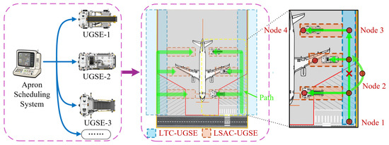
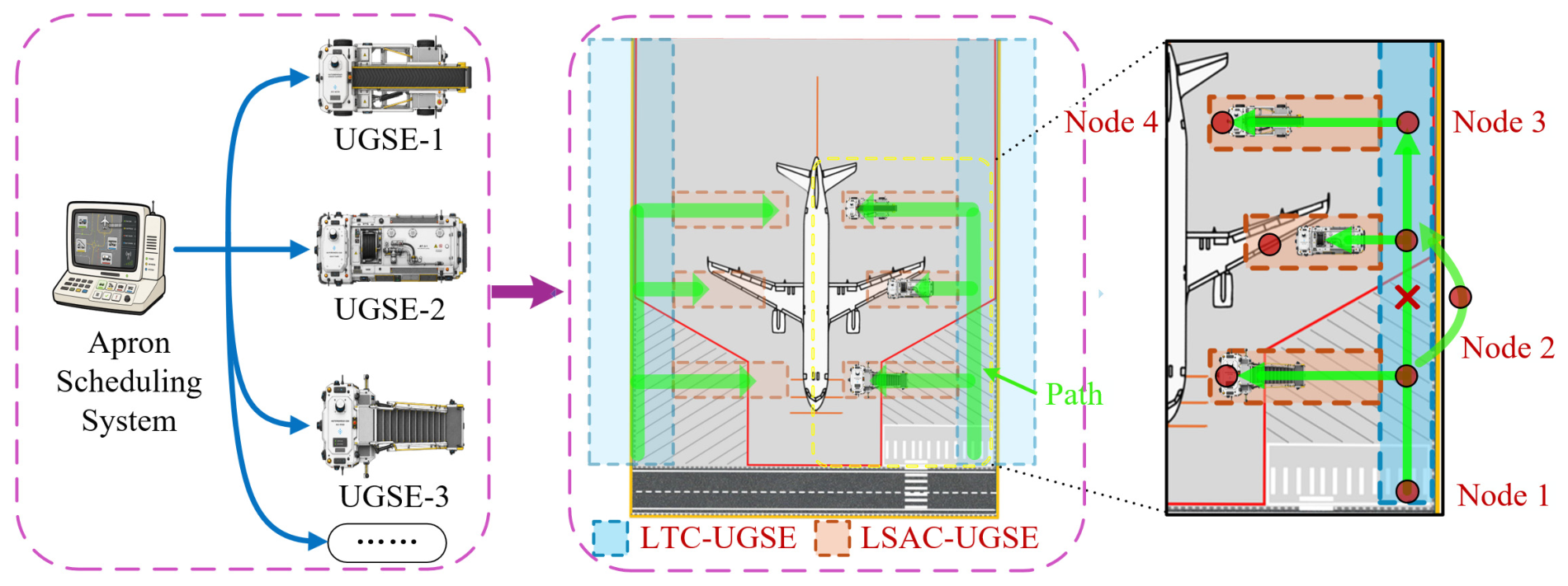
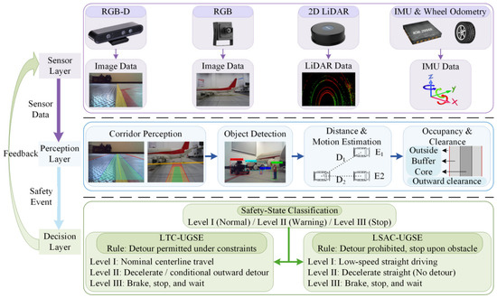
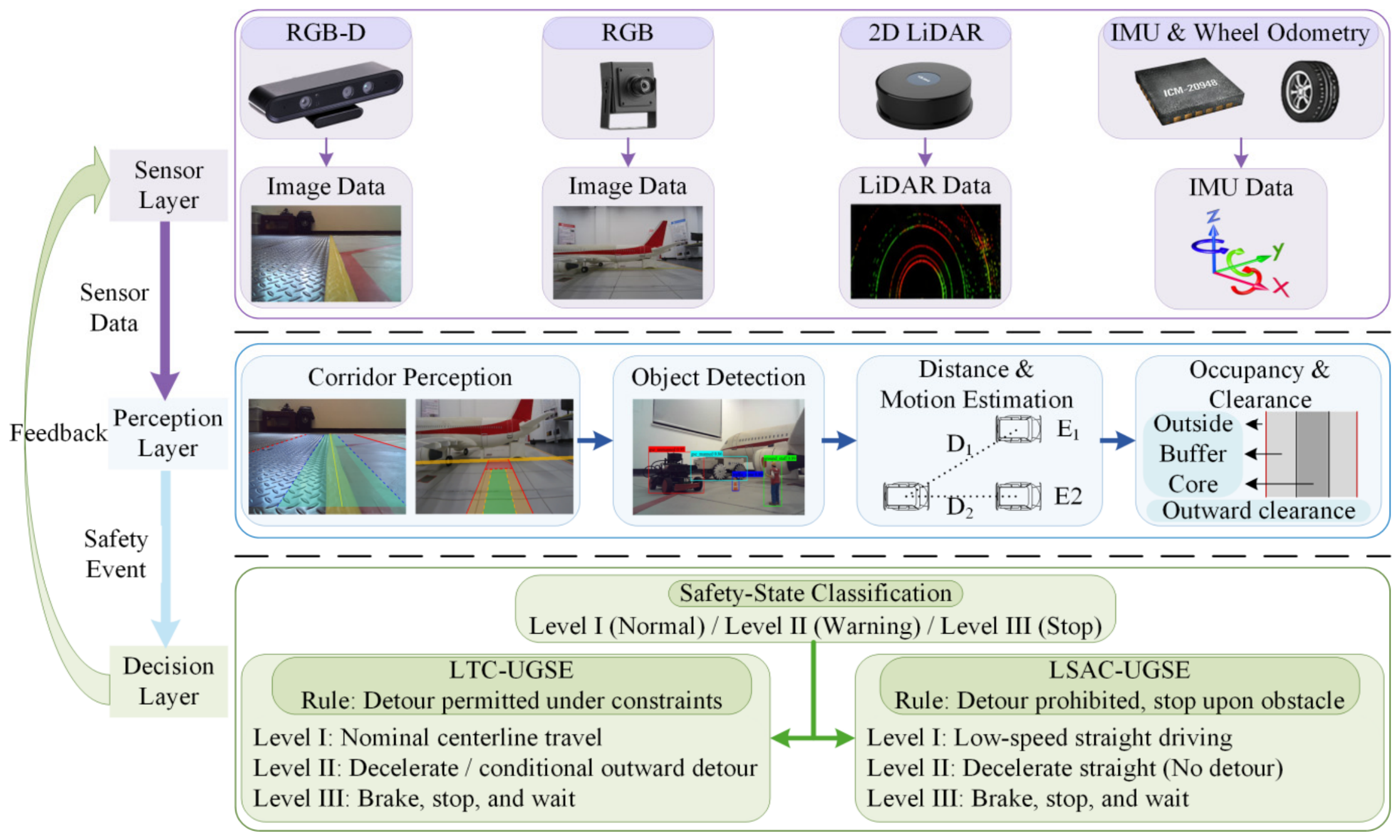
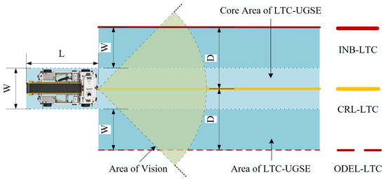
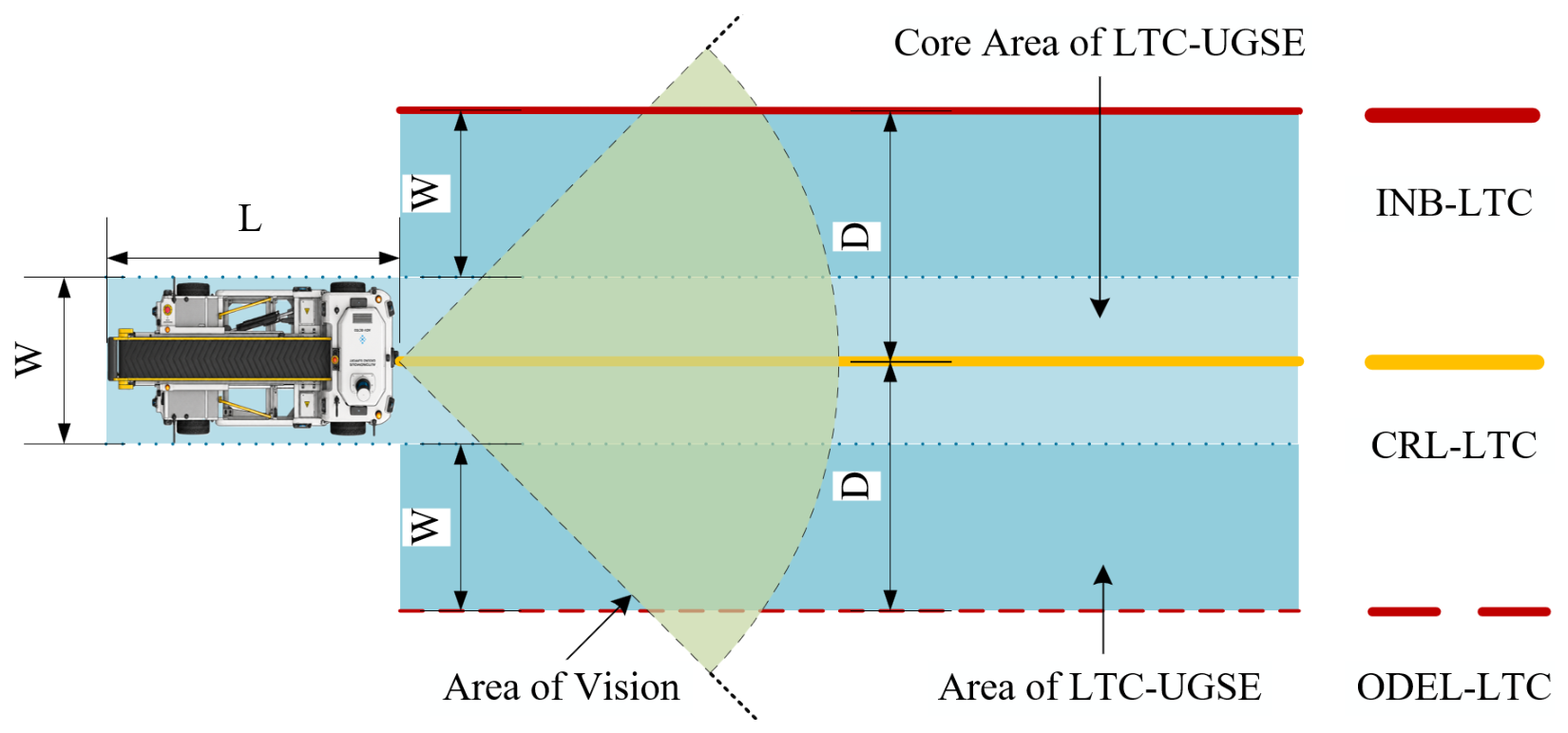
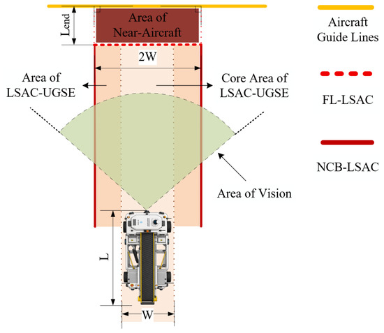
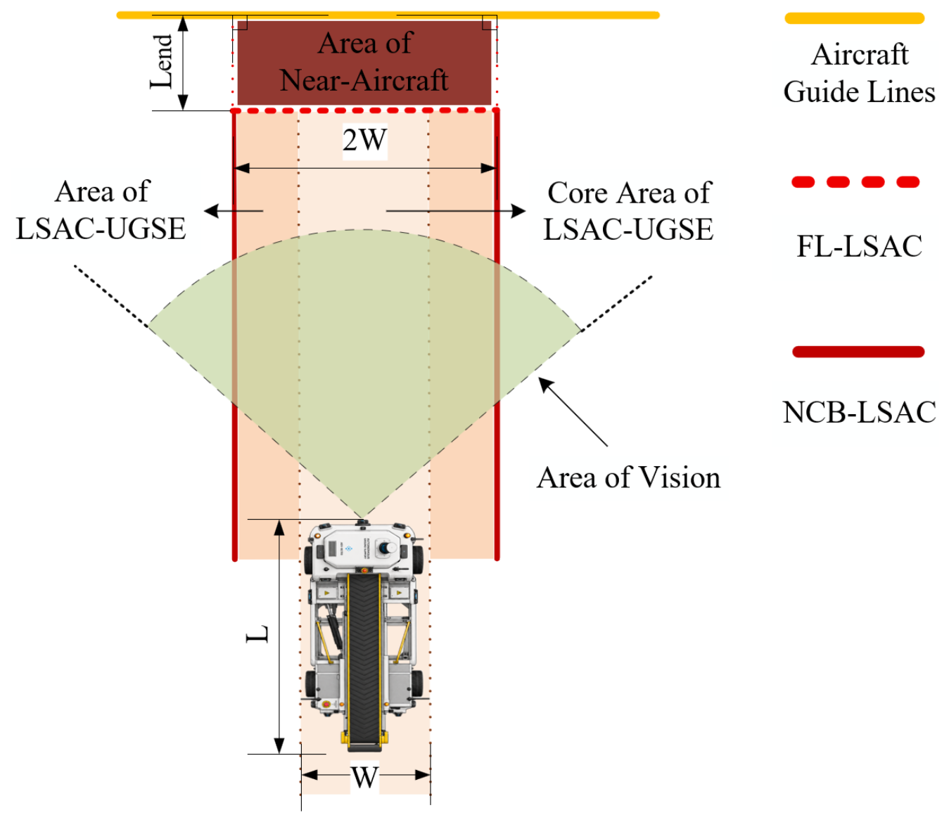
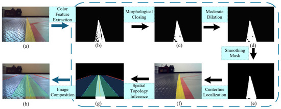
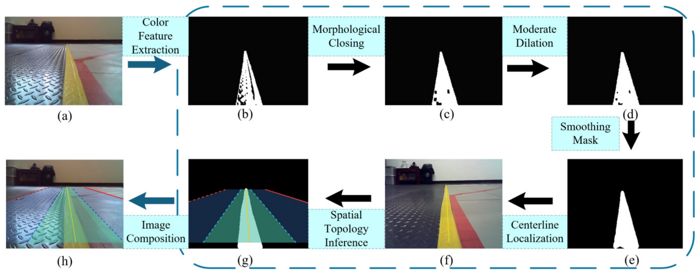
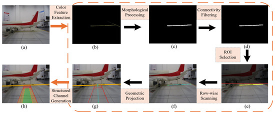
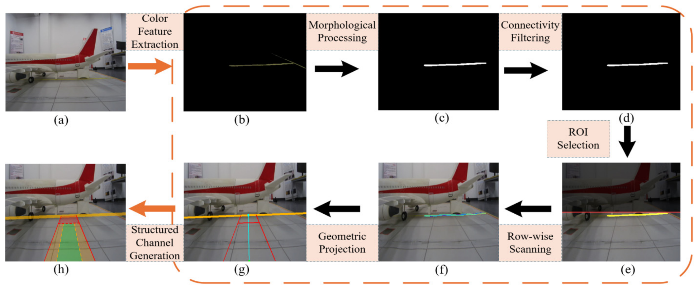
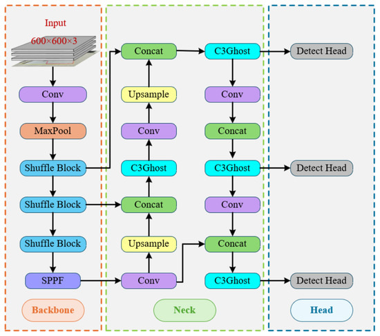
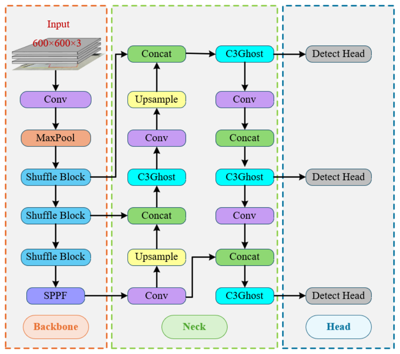
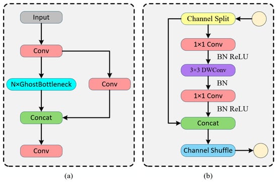
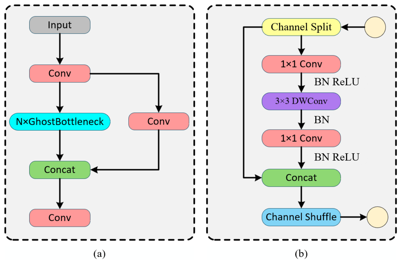
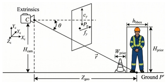
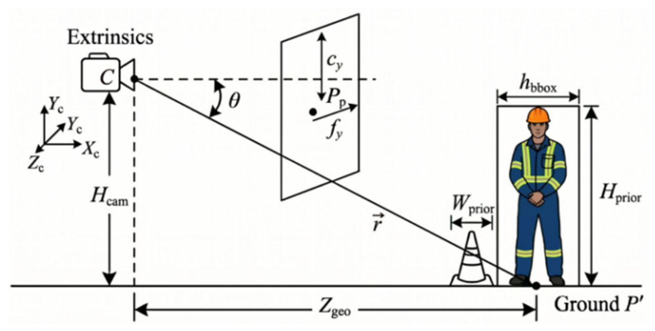
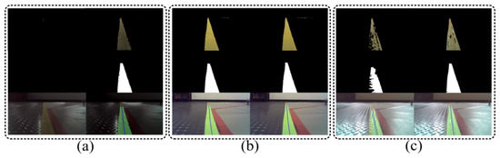
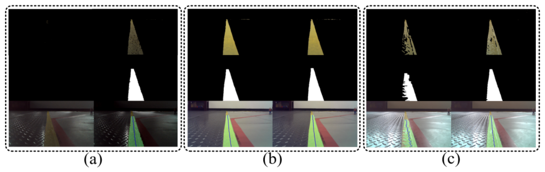
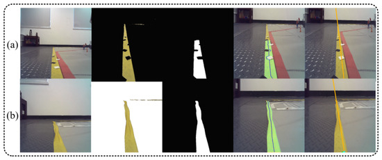
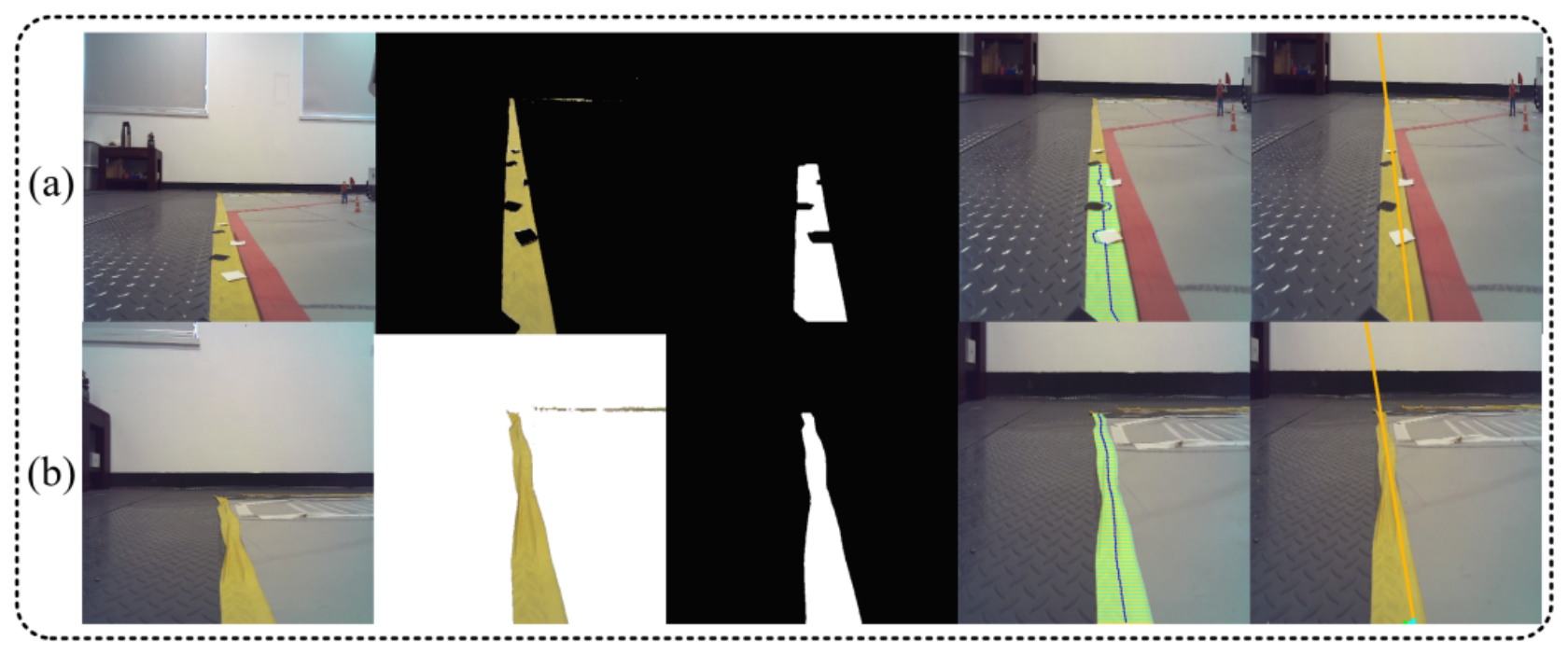
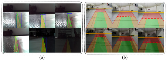
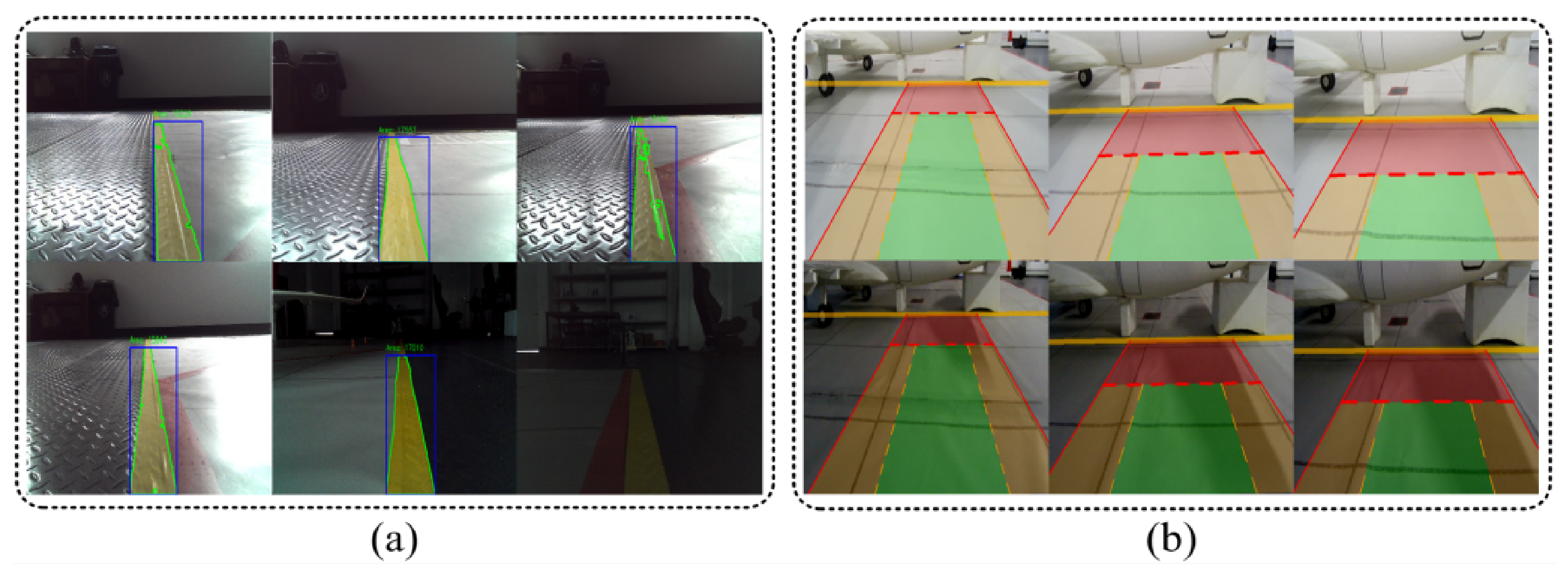
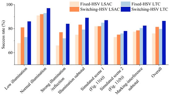
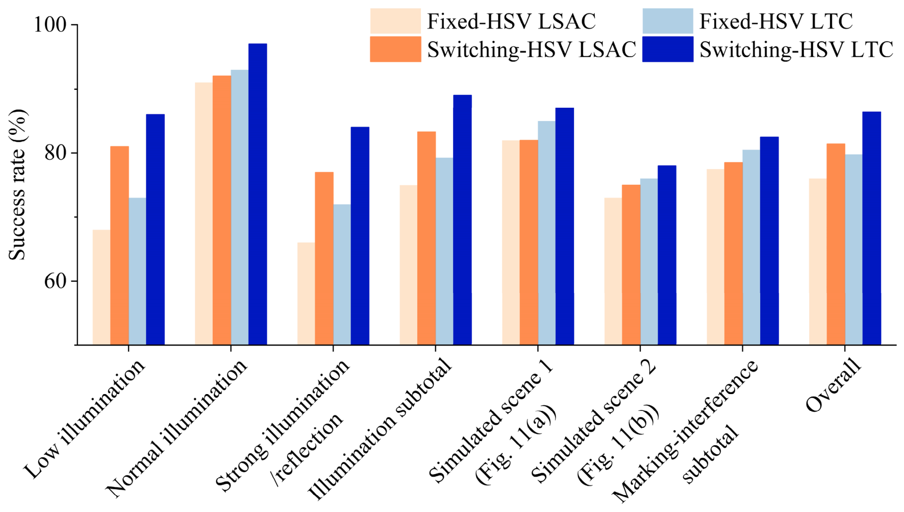
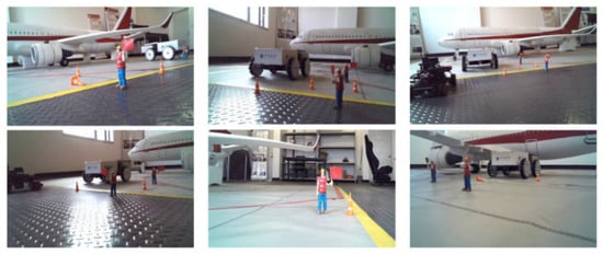
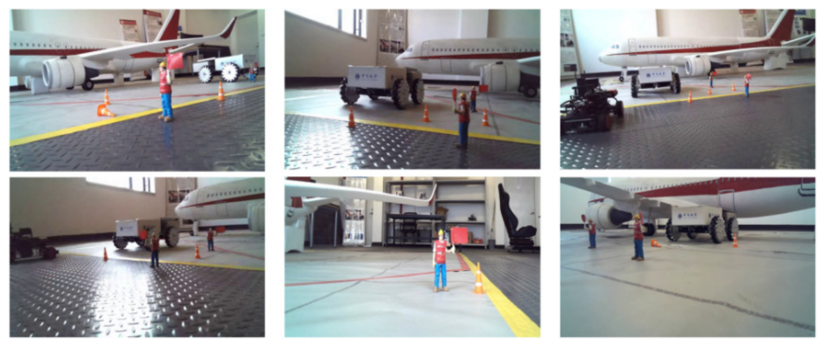
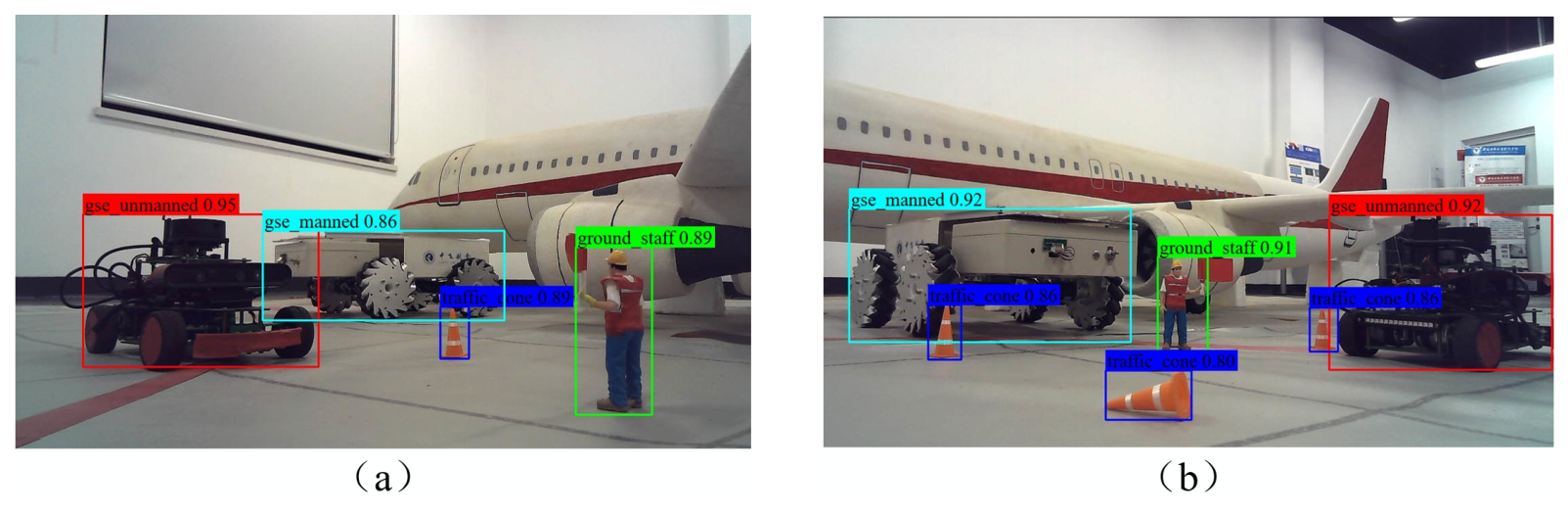
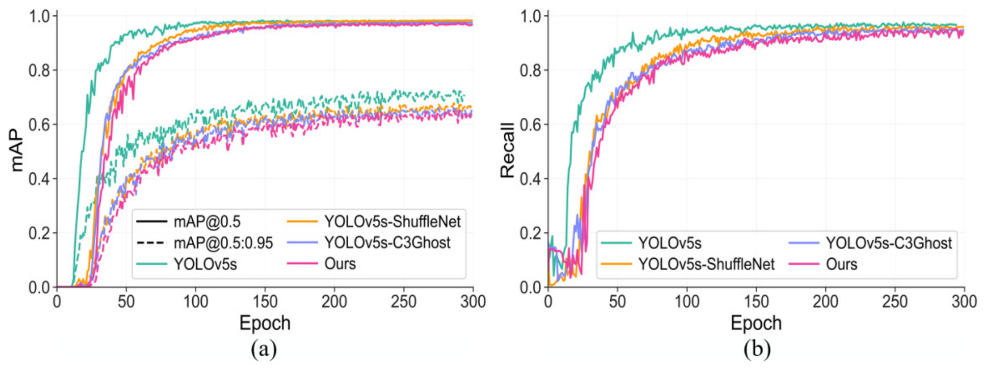
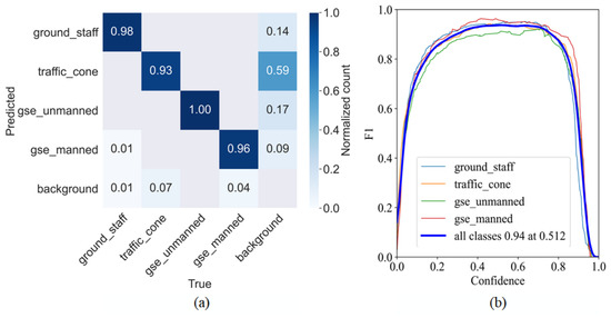
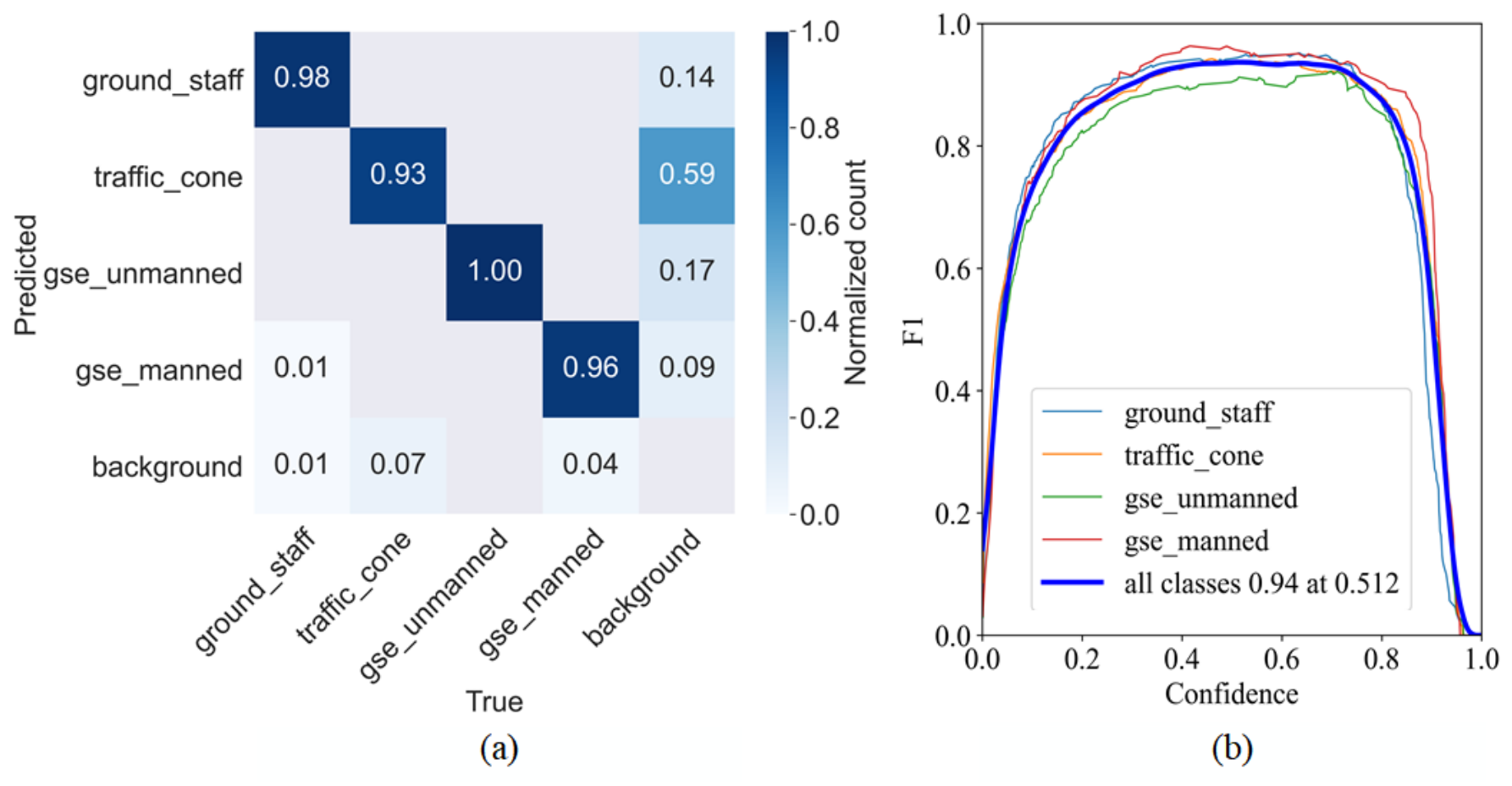
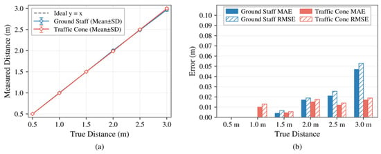
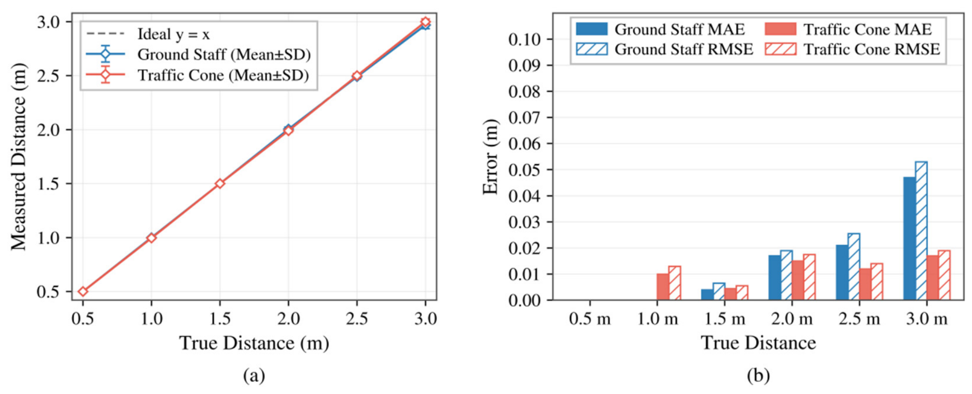
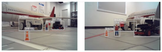
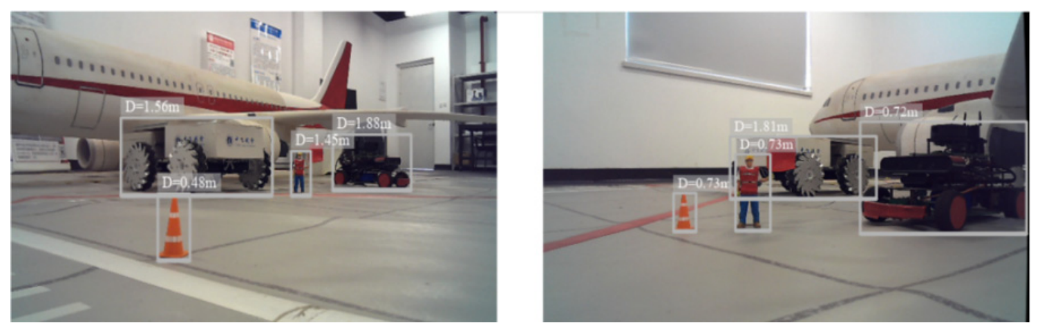
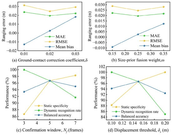
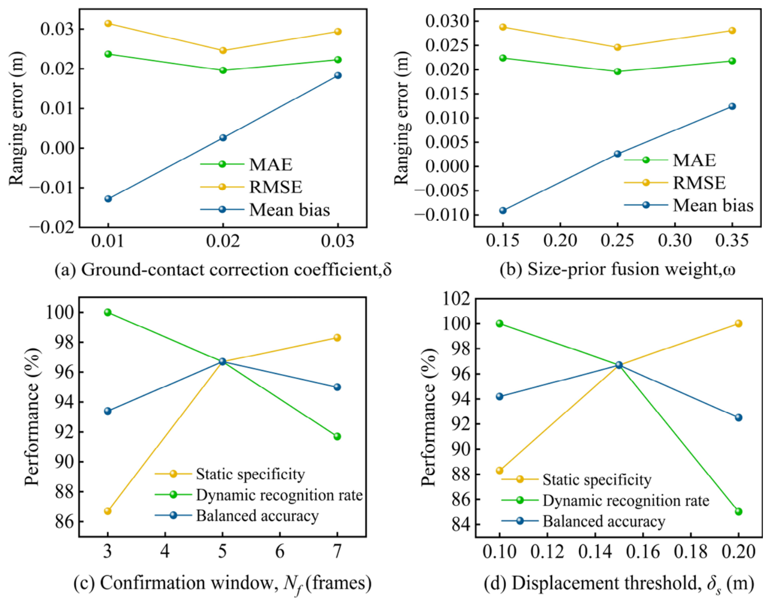
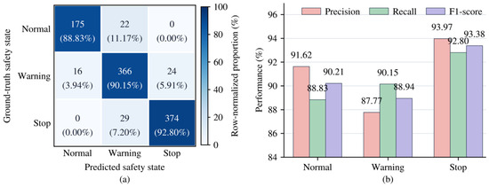
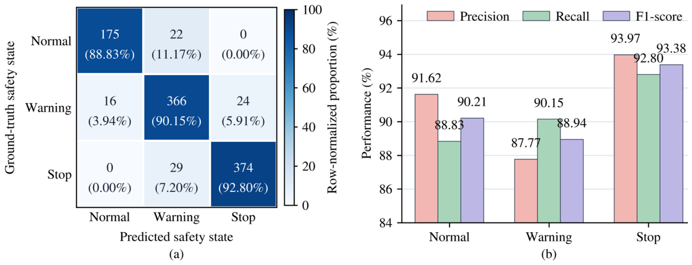
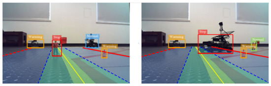
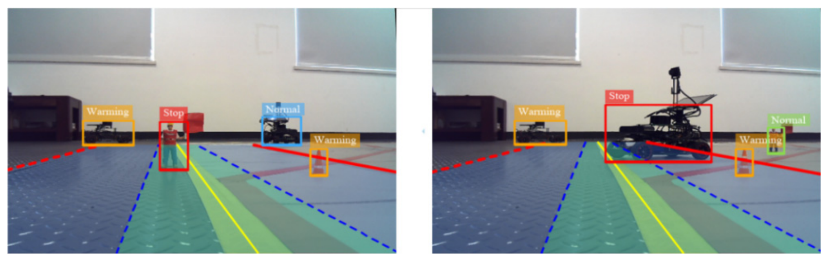
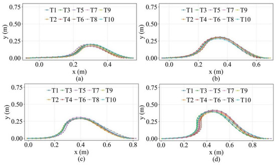
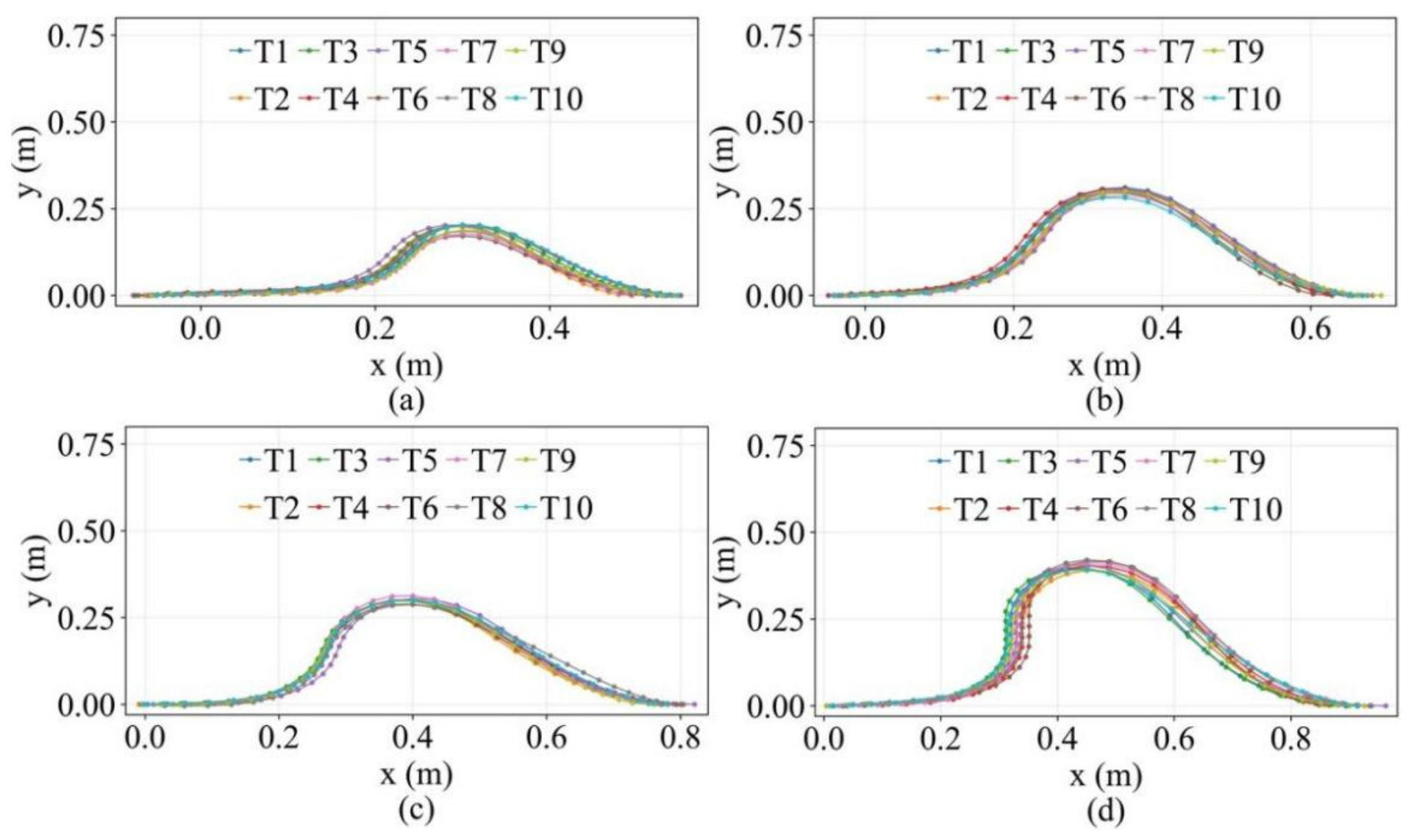
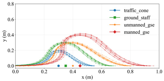
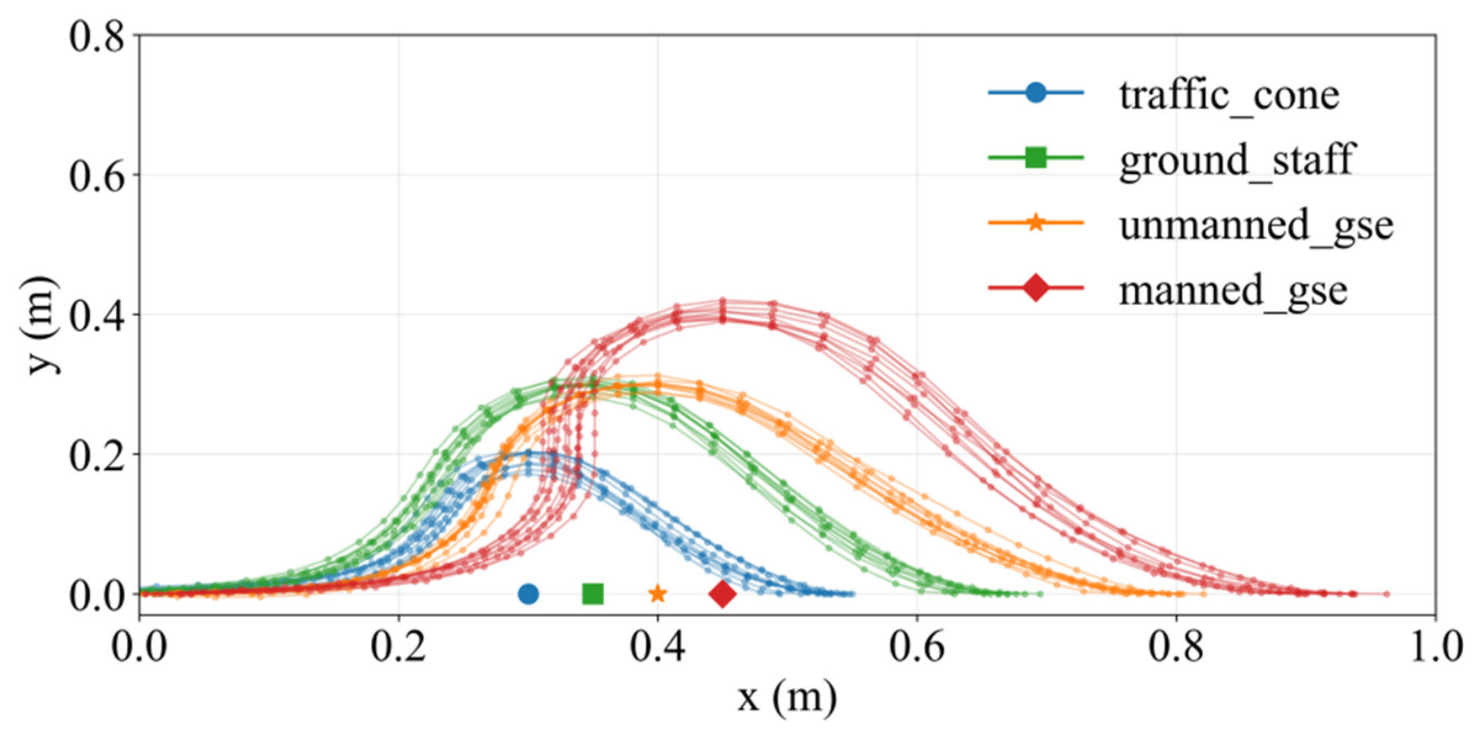
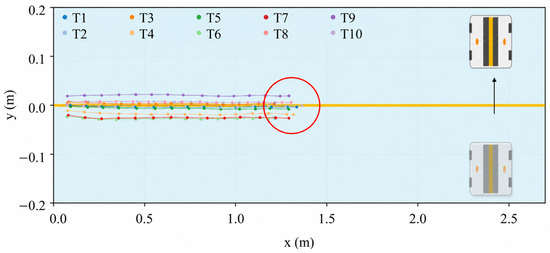
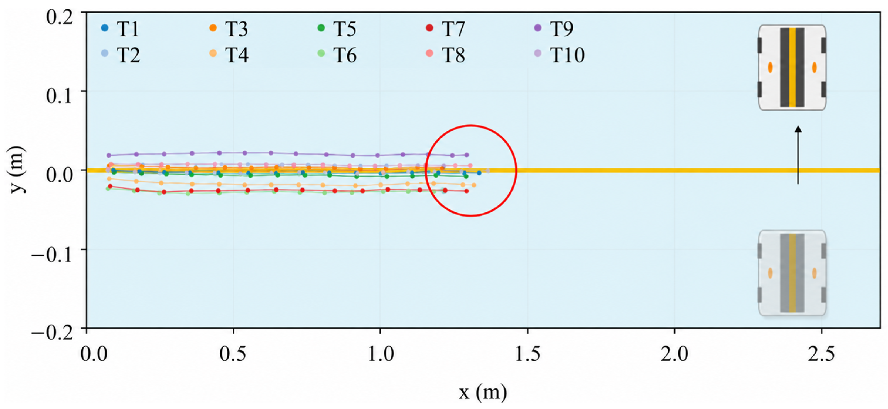
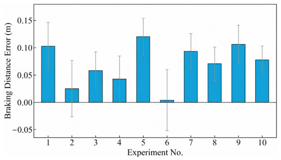
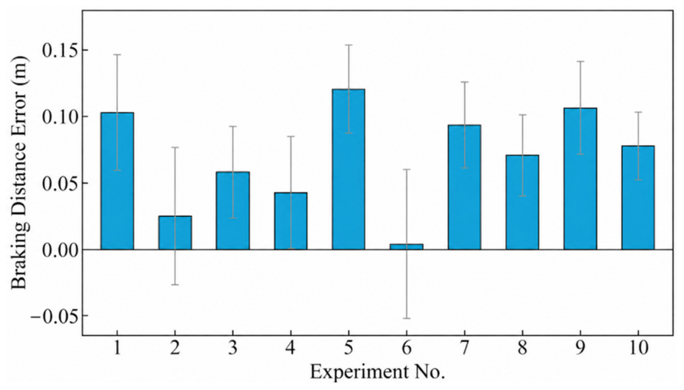
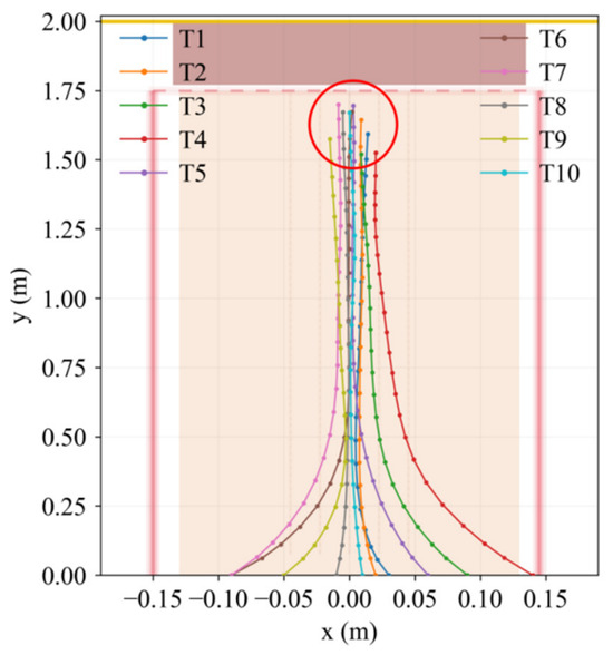
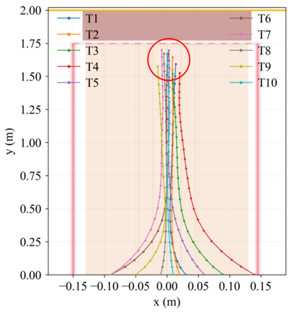
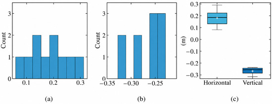
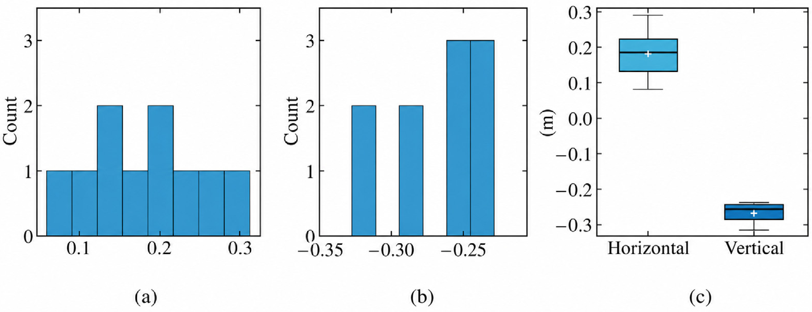

Disclaimer/Publisher’s Note: The statements, opinions and data contained in all publications are solely those of the individual author(s) and contributor(s) and not of MDPI and/or the editor(s). MDPI and/or the editor(s) disclaim responsibility for any injury to people or property resulting from any ideas, methods, instructions or products referred to in the content. |
© 2026 by the authors. Licensee MDPI, Basel, Switzerland. This article is an open access article distributed under the terms and conditions of the Creative Commons Attribution (CC BY) license.