


Abstract
Tip leakage degrades ducted fan performance and contributes to unsteady loading noise. This study investigates a wall-penetrating blade ring (WPBR) ducted fan for unmanned electric vertical takeoff and landing (eVTOL), replacing radial clearance with axial end face gaps. Six configurations of a 381 mm four-bladed rotor were evaluated at 5000 r/min under quasi-hover conditions: a conventional ducted fan, an internal blade ring rotor, and four WPBR cases with single-sided clearances of 0.8–2.0 mm. Sliding-mesh unsteady Reynolds-averaged Navier–Stokes simulations using the shear stress transport k-ω model were coupled with the Ffowcs Williams–Hawkings formulation. The WPBR formed a U-shaped cavity recirculation and redistributed the concentrated tip-region vortical structures. The 1.2 mm case retained 28.72 N of thrust, 2.1% above baseline, while reducing torque by 6.1% relative to the 0.8 mm case; its figure of merit remained lower. Its simulations predicted a reduction of 16.4 dB in the first blade-passing frequency level in the rotor plane and a predicted reduction of up to 15 dB in overall sound pressure level at 1 m. Thus, it represents a compromise among thrust, torque, and predicted acoustic performance rather than an aerodynamic optimum. A magnetically supported prototype operated up to 2000 r/min, demonstrating low-speed operability of the architecture for unmanned eVTOL propulsion.
1. Introduction
The rapid development of unmanned aerial vehicles and unmanned electric vertical takeoff and landing (eVTOL) aircraft has increased the demand for compact propulsion systems that combine high thrust density, operational safety, and low acoustic impact. Ducted fans are attractive for unmanned eVTOL propulsion because the surrounding duct can improve rotor loading, provide physical protection, and modify acoustic radiation [1]. The development of shrouded propellers and ducted fans can be traced to the pioneering experimental investigations conducted by NASA in the 1960s [2]. However, the operating clearance required between the rotating blade tips and the stationary duct-wall permits pressure-driven leakage flow. The resulting tip leakage vortex (TLV), together with its interaction with the blade wake and duct boundary layer, contributes to aerodynamic loss, unsteady surface loading, and acoustic radiation [3].
Previous studies have extensively examined the formation, identification, instability, and downstream evolution of tip leakage vortices. Numerical investigations of bubble type and conical vortex breakdown have demonstrated the complex anisotropic characteristics of the associated turbulent flow [4]. The instability of the TLV under near surge conditions has also been investigated [5], while different vortex identification criteria and their equivalent thresholds have been evaluated for complex tip leakage flows [6]. In addition to the intrinsic evolution of the TLV, external vortical disturbances can substantially alter its stability. The interaction between an incoming vortex and TLV breakdown has been shown to modify the momentum distribution within the vortex core and affect its downstream development [7,8]. Rotor–stator interactions can introduce additional disturbances, with the passage vortex generated by a downstream guide vane intensifying the unsteady evolution of the tip leakage flow [9]. Clearance nonuniformity, backflow, and rotating instability have also been shown to influence TLV stability and the onset of unsteady flow behavior [10,11]. These studies provide an important basis for understanding TLV dynamics, although most were conducted for compressor or turbomachinery configurations in which the leakage path remained a radial gap between a rotating blade tip and a stationary casing.
Because an operating clearance cannot be completely eliminated, modifying the leakage path and vortex evolution has become an important approach to controlling tip leakage flow. Different turbulence models have been assessed for predicting leakage flow through relatively large tip clearances [12]. Passive casing treatments, including circumferential grooves and L-shaped grooves, have also been proposed to modify the near wall pressure gradient, vortex stability, and flow blockage associated with TLV evolution [13,14]. Complementary studies have shown that adverse pressure gradients and incoming turbulence influence the stability and decay of wall bounded vortices [15], while wall pressure fluctuations require adequate turbulence resolution when assessing their potential acoustic effects [16]. Tip vortex behavior is also sensitive to operating condition. During hovering, descent, and landing, interactions among the rotor wake, vehicle downwash, and descent velocity may produce vortex ring states and additional flow instability [17,18]. Although these investigations demonstrate that TLV evolution can be modified, the conventional radial clearance and its associated pressure-driven leakage path are generally retained.
The generation and evolution of the TLV affect both aerodynamic performance and aeroacoustic behavior. Duct geometry optimization has been used to improve propulsion efficiency while reducing acoustic radiation [19]. For conventional ducted rotors, the tip gap is generally defined by the radial distance between the blade tip and the stationary duct-wall, and its size has been shown to strongly influence both aerodynamic and aeroacoustic performance in hover [20]. Grooved duct configurations provide another approach to modifying the blade tip region. Hu et al. [21] showed that the hovering-efficiency penalty associated with large blade tip clearance can be mitigated by adjusting the groove geometry and blade tip location, including configurations in which the blade tip extends into the stationary duct groove. Blade tip rotating shrouds represent a related concept in which a continuous ring connects the blade tips. Canepa et al. [22] showed that the leakage flow is transferred to the annular gap between the rotating ring and the stationary shroud, where leakage jets, recirculating structures, and subsequent flow re-ingestion may occur. Pereira et al. [23] further investigated a rotating shroud fan with a radial ring to casing clearance and controlled the associated leakage flow by air injection. These studies demonstrate that both casing modification and blade tip rings can substantially alter the blade tip flow; however, the resulting rotating–stationary interface and leakage pathway remain different from the wall-penetrating configuration considered in the present study.
Other investigations have examined the effects of inlet and duct shape factors on internal flow development and aerodynamic performance [24]. From an acoustic perspective, interactions among the rotor, duct boundary layer, and leakage flow can contribute to both tonal and broadband noise [25]. Numerical and experimental studies of ducted fan acoustic fields have further demonstrated the importance of source distribution, duct propagation, and observer position [26,27]. Consequently, recent ducted fan designs increasingly require a compromise among thrust, power consumption, and acoustic radiation [28,29]. An aerodynamic improvement obtained by restricting leakage does not necessarily produce an acoustic or efficiency benefit, because additional rotating surfaces and narrow clearances may increase viscous torque and unsteady loading. For unmanned eVTOL aircraft, these competing effects are particularly important because a compact propulsion unit must provide sufficient hover thrust while limiting power demand and acoustic impact.
In contrast to these related concepts, the defining feature of the wall-penetrating blade ring (WPBR) considered in this study is not the presence of a blade tip ring alone, but the topology of the rotating–stationary interface and the resulting leakage pathway. A continuous ring is integrated with the blade tips and extends radially through a split duct-wall. The conventional radial clearance within the main passage is therefore replaced by upper and lower axial end face clearances between the rotating ring and the stationary duct sections. The pressure-driven leakage flow is redirected through an annular cavity in the duct-wall before returning to the main passage. The axial clearance may consequently produce competing aerodynamic effects: a narrow clearance can restrict flow exchange but increase viscous shear, whereas a wider clearance can reduce end face friction while permitting stronger leakage through the cavity. The penetrating ring also requires a noncontact support system to avoid contact with the stationary duct. Active magnetic bearings provide a potential means of supporting the outer ring and regulating its axial position [30,31]. In the present study, a laboratory prototype is used to demonstrate the physical implementation, system integration, and low-speed operability of this magnetic support architecture. The WPBR configuration is considered specifically as a propulsion-unit concept for an unmanned eVTOL aircraft.
Against this background, the objective of this study is to determine how replacing a conventional radial tip clearance with axial end face clearances affects the aerodynamic, aeroacoustic, and preliminary structural characteristics of a ducted fan intended for unmanned eVTOL propulsion. The present work is conducted at the propulsion-unit level, while complete aircraft integration is outside the scope of this study. A conventional radial clearance configuration, an internal blade ring configuration, and four WPBR configurations with different axial clearances are compared under the same quasi-hover condition. The investigation focuses on: (1) changes in total thrust, rotor torque, and hover figure of merit; (2) reorganization of the clearance flow path and the associated changes in tip-region vortex organization and rotational strength, modeled turbulent kinetic energy (TKE), and time-averaged pressure distribution; (3) variations in the predicted blade-passing frequency components, overall sound pressure level, and acoustic directivity; and (4) the preliminary modal characteristics and low-speed operability of the magnetic support concept. The acoustic results are interpreted primarily as comparative predictions obtained using the unsteady Reynolds-averaged Navier–Stokes (URANS) equations coupled with the Ffowcs Williams–Hawkings (FW-H) formulation.
2. Materials and Methods
2.1. Geometric Configurations and Design Parameters
To isolate the influence of the blade tip boundary topology, all investigated configurations employ the same rotor core, duct profile, rotor-plane position, and nominal operating condition. The principal differences among the configurations are the presence and location of the blade tip ring and the orientation of the operating clearance. This comparative arrangement enables the aerodynamic effects associated with adding a blade tip ring to be distinguished from those caused by relocating and reorienting the clearance between the rotating and stationary components.
The baseline ducted fan has a rotor diameter D of 381 mm and consists of four blades. The 381 mm rotor is treated as a propulsion-unit-scale research model for unmanned eVTOL applications; no specific airframe, payload, or mission profile is prescribed in the present study. The blade sections are based on the NACA 6409 airfoil. The pitch-to-diameter ratio is 0.65 at the 75% radial position (r/R = 0.75), and the rotor solidity is 0.144. The duct profile is derived from the shrouded-propeller geometry reported in [2]. External mounting and fairing components that do not define the internal aerodynamic passage are excluded from the computational geometry. For all configurations, the rotor plane is located at one-third of the total duct height from the inlet. The nominal rotational speed is 5000 r/min, corresponding to a blade tip Mach number of approximately 0.29.
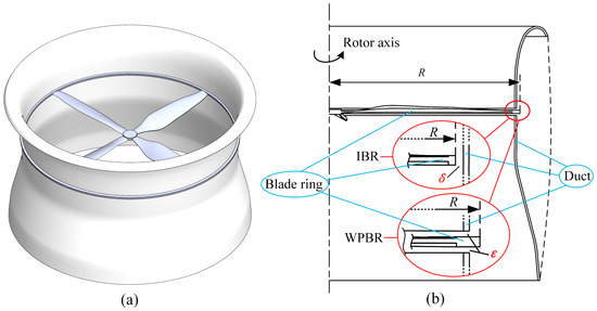
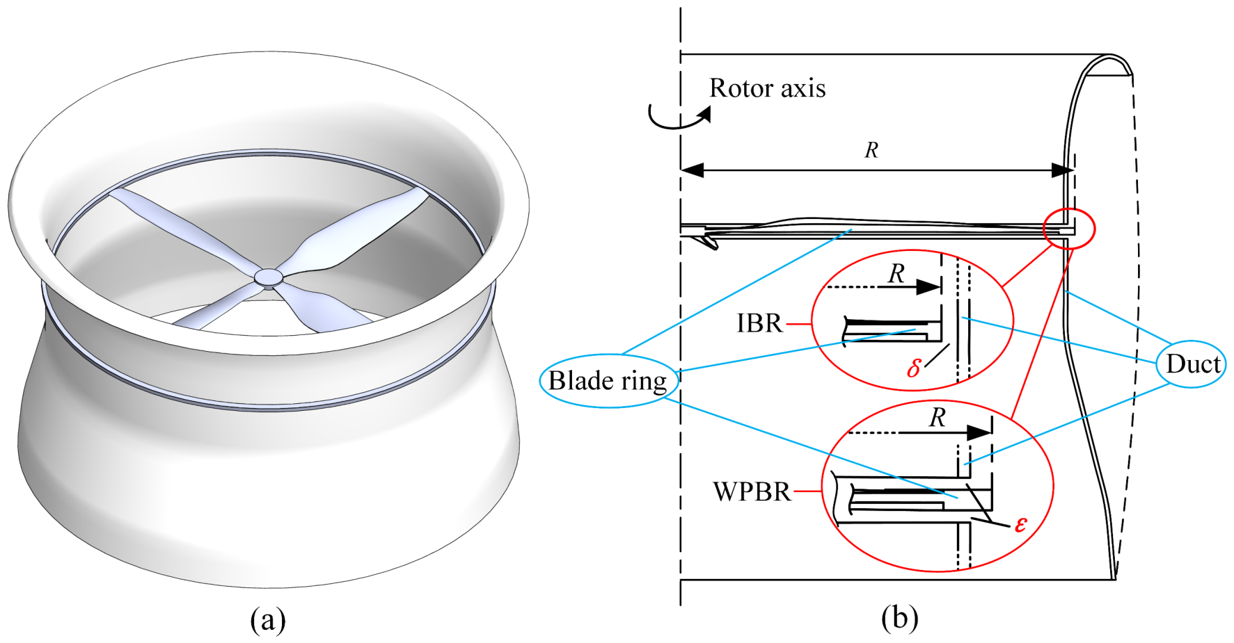
Figure 1 presents the overall ducted-fan geometry and the local definitions of the different blade tip boundary configurations. Case 1 is the conventional open-tip ducted-fan baseline. A radial clearance of δ = 2.0 mm is maintained between the blade tip and the smooth inner surface of the stationary duct. The pressure difference between the blade pressure and suction sides therefore drives the leakage flow directly through the radial gap into the main flow passage.
Figure 1.
Geometric configurations and blade tip clearance definitions: (a) overall geometry of the ducted fan; (b) conventional radial clearance configuration, internal blade ring configuration, and wall-penetrating blade ring configuration.
Case 2 is the internal blade ring (IBR) configuration. A continuous annular ring is integrated with the blade tips and remains entirely inside the main flow passage. The inner and outer diameters of the blade ring are 380 and 396 mm, respectively, and the axial thickness of the outer ring is fixed at 3.4 mm. A radial clearance of δ = 2.0 mm is retained between the outer cylindrical surface of the rotating ring and the stationary duct-wall. Case 2 therefore serves as an intermediate reference for distinguishing the aerodynamic effect of introducing a continuous blade tip ring from that of relocating and reorienting the rotating–stationary clearance in the WPBR configurations.
Cases 3–6 are the WPBR configurations. In these configurations, the blade tip ring extends radially through an annular slot formed in the split duct-wall. The conventional radial clearance is consequently removed from the main flow passage, while relative motion between the rotating ring and the stationary duct is accommodated by axial end face clearances. The inner and outer diameters of the rotating ring remain 380 and 396 mm, respectively, and the axial thickness of the outer ring remains 3.4 mm.
The axial clearance parameter ε denotes the distance from one axial surface of the rotating outer ring to the adjacent stationary duct surface. Equal clearance values are prescribed above and below the rotating ring; therefore, the upper and lower end face clearances are both equal to ε. Four single-sided axial clearances are investigated: ε = 0.8, 1.2, 1.6, and 2.0 mm, corresponding to Cases 3–6, respectively. The annular duct slot must accommodate the 3.4 mm axial thickness of the rotating ring together with the equal clearances on its upper and lower sides. The resulting total axial slot widths are therefore 5.0, 5.8, 6.6, and 7.4 mm for Cases 3–6, respectively, as summarized in Table 1.
Table 1.
Geometric definitions of the investigated ducted-fan configurations.
The selected clearance range extends from an axial gap considerably narrower than the 2.0 mm radial clearance of the conventional configuration to an equal dimensional clearance. It is used to examine the competing effects associated with stronger viscous interaction in narrow end face gaps and increased flow exchange through wider gaps. The comparison is limited to the four investigated clearance values and is not intended to establish a globally optimal axial clearance.
The penetrating blade ring requires a non-contact support arrangement to prevent direct contact with the stationary upper and lower duct sections. In the present concept, an active magnetic-bearing system is employed as a potential means of supporting the outer ring and regulating its axial position. The magnetic-bearing components are not included in the aerodynamic computational domain. A proof-of-concept prototype and its low-speed operational demonstration are presented separately in Section 4. The prototype experiment is used to demonstrate the basic operability of the support architecture rather than to validate the aerodynamic or aeroacoustic predictions at 5000 r/min.
Cases 3 and 4 were selected as representative narrow- and moderate-clearance WPBR configurations for detailed flow-field and aeroacoustic comparisons. Cases 5 and 6 were retained only to establish the clearance-dependent trend in the integral aerodynamic quantities. Therefore, the present study does not provide an acoustic ranking of all four WPBR clearances or establish a globally optimal axial clearance.
2.2. Numerical Methodology
All numerical simulations were performed using Ansys Fluent (2024 R2). The computational domain dimensions, boundary conditions, rotor speed, numerical schemes, and convergence criteria were kept consistent across all configurations. Only the local geometry and mesh associated with the blade tip clearance and annular duct slot were modified.
2.2.1. Aerodynamic Setup and Flow Solver Settings
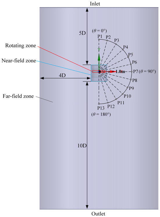
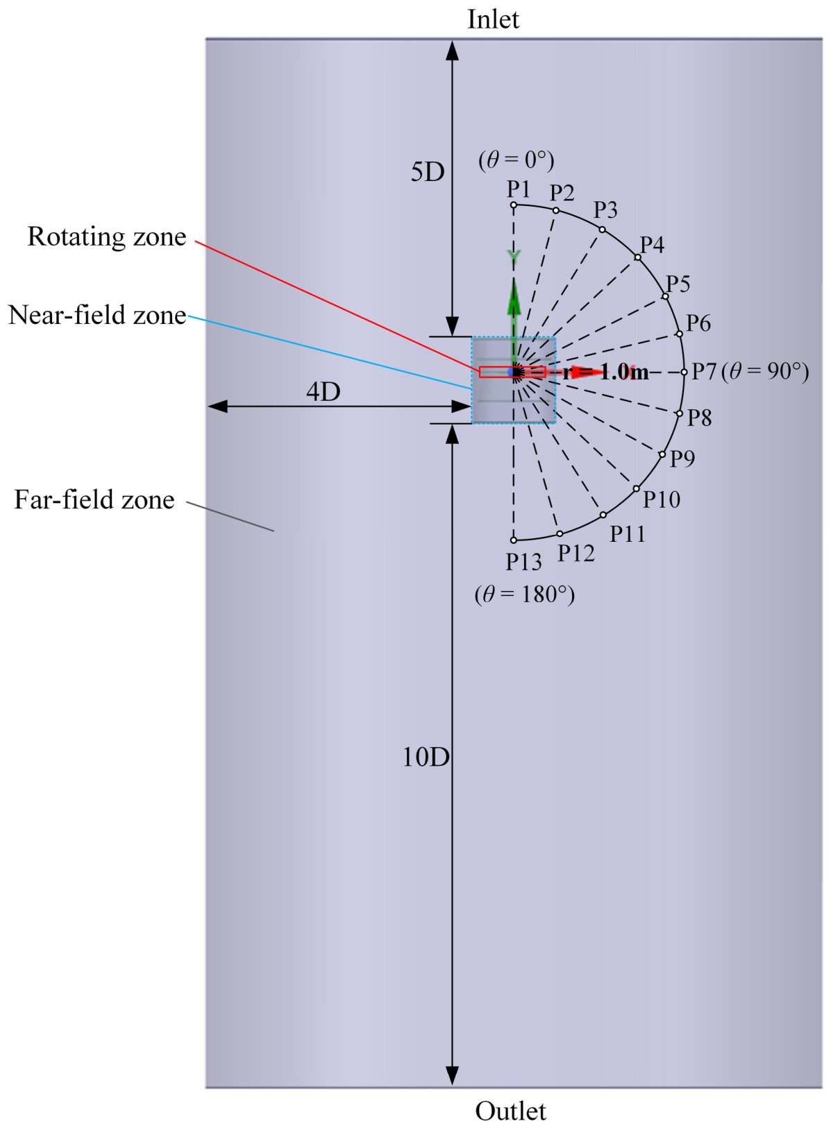
The computational domain was divided into a rotating zone, a stationary near-field zone, and a stationary far-field zone, as shown in Figure 2. The rotating zone encloses the rotor assembly, while the near-field zone contains the duct and annular-slot region and is surrounded by the outer far-field domain. The rotor diameter was D = 381 mm. The velocity inlet was located approximately 5D upstream of the near-field, the downstream pressure outlet was positioned approximately 10D downstream, and the outer cylindrical boundary was located approximately 4D from the near-field. These distances were selected to provide sufficient separation between the external boundaries and the rotor-induced inflow and wake regions, thereby reducing direct boundary effects on the ducted-fan flow field. The outer boundary was also specified as a pressure outlet to permit ambient flow entrainment and radial wake expansion.
Figure 2.
Computational domain and observer arrangement.
Thirteen virtual observers were arranged on a semicircular arc with a radius of 1.0 m from the rotor center, as shown in Figure 2. The observer angle θ ranged from 0° at the duct inlet to 180° at the outlet in increments of 15°. Accordingly, P1, P7, and P13 correspond to θ = 0°, θ = 90°, and θ = 180°, respectively. The observer at θ = 90° was located in the rotor plane. The observer locations were identical for all configurations.
A uniform axial velocity of 1 m/s was prescribed at the inlet as a weak background inflow representative of the quasi-hover condition. At the nominal rotational speed of 5000 r/min, this condition corresponded to an advance ratio of approximately J = 0.03, representing quasi-hover rather than a strictly static hover condition. The corresponding blade tip Mach number was approximately 0.29, indicating that the present operating condition remained within the low-subsonic regime. Air at standard atmospheric conditions was used as the working fluid. The flow was assumed to be incompressible and isothermal, with constant fluid properties.
All blade, hub, blade ring, duct-wall, and annular-slot surfaces were treated as no-slip walls. The blades, hub, and blade ring rotated together within the rotating fluid domain, whereas the duct, slot walls, and surrounding fluid domain remained stationary. The rotating and stationary domains were coupled through sliding-mesh interfaces. The magnetic-bearing components and external support structures were excluded from the aerodynamic computational domain because they were located outside the internal flow passage.
A three-dimensional unsteady Reynolds-averaged Navier–Stokes formulation was used to calculate the flow field. Considering the adverse pressure gradients, blade tip separation, and complex vortex dynamics in the ducted fan, the shear stress transport k-ω model was employed for turbulence closure. Pressure–velocity coupling was achieved using the Coupled algorithm. A second-order scheme was used for pressure interpolation, while second-order upwind schemes were adopted for the momentum, TKE, and specific dissipation rate equations. Time advancement employed a bounded second-order implicit formulation.
A sequential steady to transient procedure was adopted. First, a steady multiple reference frame (MRF) calculation was performed at 5000 r/min for approximately 2500 iterations to establish the initial flow field. Convergence was assessed from scaled residuals below 1.0 × 10⁻⁵, together with stabilization of the monitored thrust and torque. The converged steady solution was subsequently used to initialize the transient sliding-mesh calculation.
The transient calculation was initially advanced for three complete rotor revolutions without acoustic sampling to reduce the numerical adjustment associated with the transition from the steady MRF solution. Flow field and acoustic source data were then recorded for another eight complete revolutions. The physical time step was 5.0 × 10⁻⁵ s, corresponding to 240 time steps per revolution at 5000 r/min. For the four-bladed rotor, the blade-passing frequency (BPF) was 333.3 Hz, and each blade passing period was resolved using 60 time steps. The eight sampled revolutions therefore contained 1920 time steps and 32 blade passing events.
The total axial thrust T was obtained by summing the axial forces acting on the rotating rotor assembly and the stationary duct surfaces. The rotor torque Q was evaluated about the rotational axis by integrating the aerodynamic moments over all rotating surfaces, including the blades, hub, and blade ring where applicable. The stationary duct surfaces were excluded from the reported rotor torque. The hover figure of merit was evaluated as
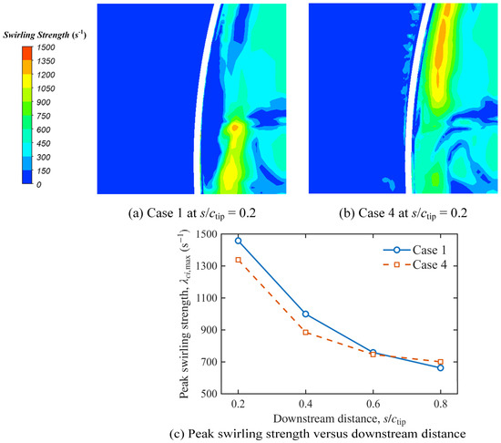
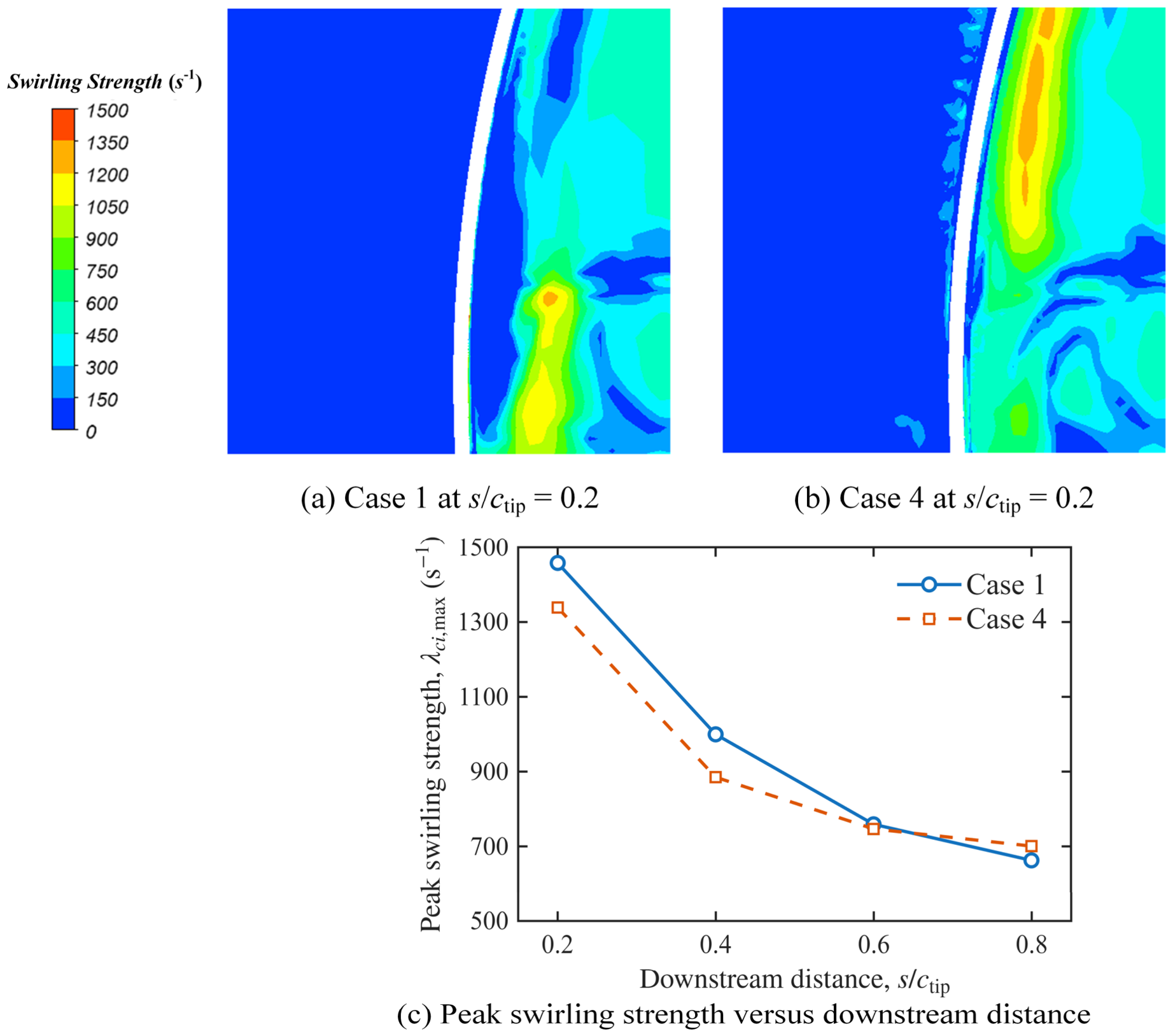
where Ω is the angular velocity, ρ (1.225 kg/m3) is the air density, and A is the rotor disk area. The reported aerodynamic quantities were averaged over the eight sampled revolutions. To complement the Q-criterion visualization, the swirling strength λci was evaluated on X-Z cross-sectional planes located at s/ctip = 0.2, 0.4, 0.6, and 0.8 downstream of the blade tip trailing edge region, where ctip = 16 mm and s denotes the downstream distance. The peak swirling strength λci,max was extracted within the same fixed blade tip region window for Cases 1 and 4.
2.2.2. Aeroacoustic Prediction Methodology
The unsteady surface pressure data obtained from the sliding-mesh URANS calculations were coupled with the FW-H formulation to predict acoustic radiation. Impermeable solid FW-H source surfaces were assigned to the blades, hub, blade ring, duct inner wall, and annular-slot walls. The same source-surface selection principle was applied to all configurations, except for surfaces that were absent in a particular geometry.
The solid surface FW-H formulation accounted for the thickness and loading contributions associated with the rotating and stationary solid boundaries. At the present low-Mach number condition, the method was primarily used to compare periodic loading noise and relative acoustic differences among the configurations. Because the unresolved turbulent scales were modeled within the URANS framework, the absolute high-frequency broadband levels were interpreted with caution.
A physical time step of 5 × 10⁻⁵ s was adopted, corresponding to 240 time steps per rotor revolution and approximately 60 time steps per blade-passing period at 5000 r/min. A separate formal time-step-independence assessment was not performed. However, the adopted temporal resolution was selected to resolve the dominant BPF harmonics that form the primary basis of the present comparative tonal analysis.
FW-H sampling was activated after the initial three transient revolutions and continued for eight complete rotor revolutions. During the subsequent sampling interval, the monitored thrust and torque exhibited periodic fluctuations about stable mean values without any systematic drift, and their transient mean values remained close to those obtained from the converged MRF solution. Pressure data were recorded at every physical time step, giving a sampling frequency of 20 kHz and a Nyquist frequency of 10 kHz. FW-H source data were acquired over eight complete rotor revolutions, corresponding to 0.096 s. After the default receiver signal pruning in Fluent, the resulting acoustic pressure histories contained 1888 uniformly spaced samples over approximately 0.0944 s, giving a frequency resolution of approximately 10.59 Hz. To assess the stability of the dominant tonal response, the existing receiver histories were additionally reprocessed using terminal sampling windows of two, four, and six rotor revolutions with a common end time.
The acoustic pressure histories and spectra were obtained directly using the built-in FW-H postprocessing functions in Ansys Fluent. A Hanning window and fast Fourier transform were applied to the sampled acoustic signals. Sound pressure level (SPL) values were referenced to 20 μPa, and identical signal processing settings were used for all observers and configurations. The unweighted overall sound pressure level (OASPL) was calculated by integrating the resolved spectrum from 10.59 Hz to 10 kHz. The same integration range was used for all observers and configurations.
A direct acoustic validation of the present WPBR configuration at the nominal 5000 r/min condition is not currently available. As an external reference, Hirono et al. [28] compared tonal predictions obtained using a full-annulus URANS-based hybrid acoustic method with anechoic-chamber measurements for an electric ducted fan. Good agreement was obtained for the first few BPF harmonics in some configurations, whereas configuration- and direction-dependent over- and underpredictions were also observed; nevertheless, the relative trends in tonal SPL among the investigated designs were captured well.
The acoustic results are therefore used mainly to compare tonal components, directivity, and relative configuration-to-configuration variations. Because the small-scale turbulent fluctuations are modeled rather than explicitly resolved by URANS, no quantitative claim is made regarding convergence of the complete broadband spectrum. In particular, the predicted high-frequency broadband levels and their absolute differences should not be interpreted as experimentally validated values.
2.2.3. Mesh Generation and Grid Independence Assessment
A predominantly hexahedral structured mesh was generated for the rotating fluid domain, while a hybrid mesh comprising structured and unstructured elements was employed in the stationary domain. Local refinement was applied near the blade leading and trailing edges, blade tip region, rotor wake, sliding interfaces, blade ring, and annular duct slot. Consistent local sizing principles were used for all configurations to reduce mesh-induced differences among the comparative cases.
Prism layers were generated on all solid-wall surfaces using the Smooth Transition method. The blades and blade ring form an integrated rotating assembly, for which 16 prism layers were applied. Three prism layers were generated on the stationary duct and annular-slot wall surfaces. Additional local mesh refinement was applied in the blade tip clearance, blade-ring, and annular-cavity regions. The resulting nondimensional wall distance remained predominantly below y+ = 1.
In the final volume mesh, approximately 16 cells were distributed across the smallest single-sided axial clearance of 0.8 mm. The minimum orthogonal quality of the final mesh was 0.20. Consistent near-wall treatments and comparable local mesh sizing strategies were applied to all configurations to minimize mesh-induced differences among the comparative cases.
A grid independence assessment was conducted for the conventional baseline configuration using coarse, medium, and fine meshes. The rotating domain cell counts were 2.81, 4.22, and 6.07 million, while the corresponding total cell counts were 6.58, 9.63, and 14.45 million. Total thrust, torque, and figure of merit were selected as the assessment quantities, as summarized in Table 2.
Table 2.
Grid independence assessment for the conventional configuration at 5000 r/min.
The total thrust changed by approximately 0.71% when the mesh was refined from the coarse to the medium level. Further refinement from the medium to the fine mesh resulted in a thrust difference of only approximately 0.07% and a torque difference of approximately 0.14%, while the figure of merit remained unchanged to the reported precision. The medium mesh was therefore adopted as the basis for the subsequent transient calculations.
Additional local refinement was introduced for the blade ring and annular-slot geometries. Consequently, the final mesh sizes of Cases 2–6 ranged from approximately 11 to 15 million cells, depending on the clearance width and local cavity geometry. The same near-wall treatment and local-refinement principles were maintained among all configurations.
Because the WPBR introduces narrow axial clearances and recirculating flow within the annular duct-wall cavity, an additional local mesh-sensitivity assessment was performed for Case 3, which has the smallest single-sided axial clearance of 0.8 mm and therefore represents the most demanding WPBR configuration in terms of local spatial resolution. The current production mesh contained approximately 14.66 million cells and about 16 cells across the 0.8 mm clearance. A locally refined mesh increased the total cell count to approximately 16.54 million and the number of cells across the clearance to approximately 20, while retaining the same near-wall treatment, numerical schemes, and solver settings.
As shown in Table 3, further local refinement changed the thrust from 30.25 to 30.12 N and the torque from 0.870 to 0.866 N·m, corresponding to relative differences of approximately 0.43% and 0.46%, respectively. The figure of merit changed from 69.10% to 68.97%. These small variations indicate that the adopted production mesh provides adequate resolution of the narrow axial-clearance region for the integral aerodynamic comparisons presented in this study.
Table 3.
Local mesh sensitivity assessment for Case 3 with a 0.8 mm axial clearance.
The grid assessment demonstrates convergence of the integral aerodynamic quantities. It does not independently establish convergence of the detailed vortex core structure, wall pressure fluctuations, or absolute broadband acoustic levels. These local flow and acoustic results are therefore interpreted primarily as comparative trends within the adopted URANS and mesh framework.
3. Results and Discussion
3.1. Overall Aerodynamic Performance
Six configurations were evaluated under the same quasi-hover condition at 5000 r/min with an axial inflow velocity of 1 m/s. These included the conventional ducted fan with a 2.0 mm radial clearance (Case 1), the internal blade ring configuration with the same radial clearance (Case 2), and four WPBR configurations with single-sided axial clearances of 0.8, 1.2, 1.6, and 2.0 mm (Cases 3–6). The time-averaged aerodynamic performance of the six configurations is summarized in Table 4. All aerodynamic quantities reported in this section are numerical predictions at the 5000 r/min design condition. No matched thrust or torque measurements are presently available at this rotational speed; therefore, the reported absolute values and performance differences have not been experimentally validated at the design condition. In the table, CT represents thrust coefficient, CQ represents torque coefficient, and FM represents figure of merit.
Table 4.
Aerodynamic performance of the investigated configurations.
The conventional configuration produced a thrust of 28.131 N, a torque of 0.702 N·m, and the highest figure of merit of 76.8%. Adding an internal blade ring in Case 2 increased thrust by approximately 3.6%, but also increased torque by approximately 10.4%, reducing the figure of merit to 73.4%. The internal ring therefore provided a moderate thrust benefit at the expense of additional power consumption.
Among the WPBR configurations, Case 3 with the smallest axial clearance produced the highest thrust of 30.250 N, corresponding to an increase of approximately 7.5% relative to Case 1. However, it also produced the highest torque of 0.870 N·m and a reduced figure of merit of 69.1%. This result indicates that the narrowest axial clearance enhances rotor loading but introduces a substantial torque penalty.
As the axial clearance increased from 0.8 to 2.0 mm, thrust decreased monotonically, while the torque dropped sharply between 0.8 and 1.2 mm and then remained approximately constant at 0.815–0.817 N·m. The figure of merit consequently decreased from 69.1% to 66.4%. These trends indicate that the axial clearance modifies both the clearance-flow organization and the aerodynamic loading of the rotating assembly. The pronounced torque decrease between the 0.8 and 1.2 mm configurations therefore reflects the integrated response of the blades, hub, and blade ring, rather than being assigned to a single surface contribution.
Case 4 retained a thrust of 28.724 N, approximately 2.1% higher than that of Case 1. Relative to Case 3, its torque decreased from 0.870 to 0.817 N·m, corresponding to a reduction of approximately 6.1%, although its thrust and figure of merit also decreased. Therefore, Case 4 is not identified as an aerodynamic optimum. Instead, Cases 3 and 4 were selected as representative narrow- and moderate-clearance WPBR configurations for the subsequent detailed flow-field and aeroacoustic analyses. Case 3 represents the smallest axial clearance and the highest rotor loading, whereas Case 4 avoids the peak torque of Case 3 while retaining a modest thrust benefit relative to the conventional baseline. Cases 5 and 6 retain the same WPBR topology and differ from Cases 3 and 4 only in the larger axial-clearance size. Their integral aerodynamic results continue the same clearance-dependent trend, with decreasing thrust and figure of merit as the clearance increases. Therefore, Cases 5 and 6 are retained to establish the overall clearance-dependent aerodynamic trend, while the detailed flow-field and aeroacoustic comparisons focus on Cases 1–4 to avoid repetitive analysis of geometrically similar WPBR configurations.
3.2. Clearance Flow Topology and Vortex Evolution
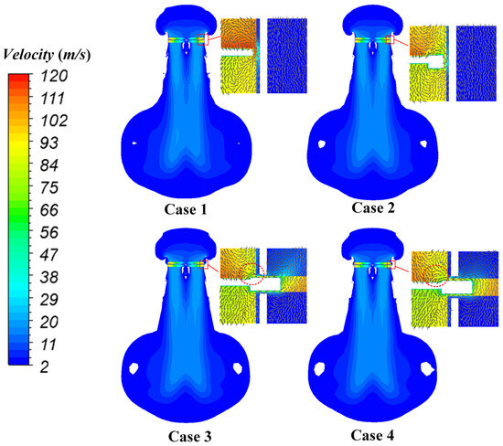
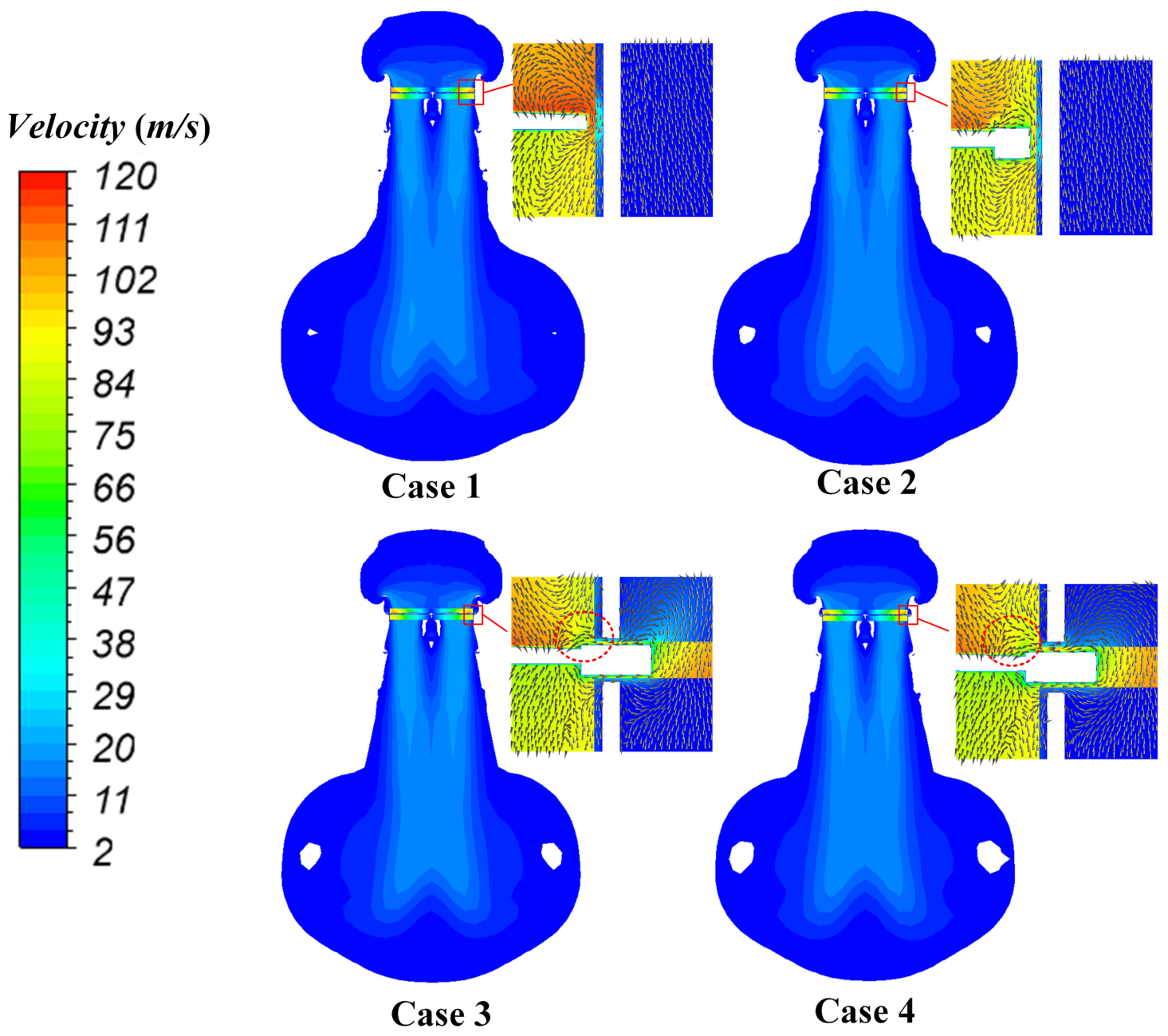
To clarify the flow mechanisms underlying the aerodynamic performance variations discussed in Section 3.1, the clearance flow topology and vortex evolution are compared for four representative configurations. Figure 3 presents the midplane velocity distributions and enlarged velocity vectors in the blade tip and clearance regions. Regions with velocity magnitudes below 2 m/s are displayed in white to highlight the wake boundaries, while the local vectors indicate the flow direction within the clearance regions.
Figure 3.
Midplane velocity distributions and near-clearance velocity vectors for Cases 1–4.
In the conventional configuration, Case 1, the pressure difference between the blade pressure and suction sides drives the tip leakage flow directly through the radial clearance, producing a concentrated leakage jet and shear layer near the blade tip. In Case 2, the internal blade ring restricts the direct radial penetration of the leakage flow. However, the radial clearance retained between the rotating ring and the stationary duct-wall continues to generate a circumferential shear layer. The internal ring therefore redistributes, rather than completely removes, the radial clearance leakage flow.
The WPBR configurations, Cases 3 and 4, exhibit a distinctly different leakage path. The flow moves radially outward through the lower axial clearance, passes upward through the annular duct-wall cavity, and re-enters the main passage through the upper clearance, forming a U-shaped recirculation path around the rotating ring. The returning cavity flow interacts with the main passage flow and produces a localized stagnation and blockage region near the upper clearance. Compared with Case 3, the wider clearance in Case 4 permits stronger flow exchange between the cavity and the main passage, which is consistent with the reduction in thrust observed as the axial clearance increases. Meanwhile, the wider axial clearance in Case 4 reduces the local velocity gradient near the rotating end faces, indicating weaker local viscous interaction. However, because the total rotor torque includes the combined contributions of the blades, hub, and blade ring, the present results do not isolate the end-face contribution to the torque reduction from Case 3 to Case 4. The observed decrease in total torque is therefore interpreted as the combined response of the rotating assembly to the modified clearance-flow field and aerodynamic loading. This comparison shows that the aerodynamic distinction of the WPBR arises primarily from the relocation and reorientation of the clearance flow path rather than from the presence of the blade tip ring alone: Case 2 retains a radial ring duct clearance and its associated circumferential shear layer, whereas the WPBR redirects the leakage flow through the axial clearances and duct-wall cavity.
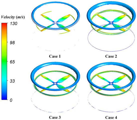
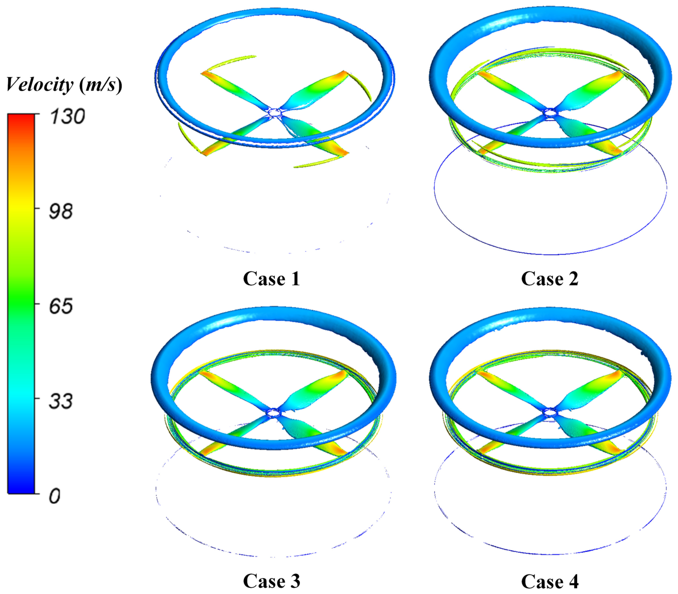
The influence of the clearance topology on the three-dimensional vortical structures is further illustrated by the Q-criterion iso-surfaces in Figure 4. For all configurations, the iso-surfaces were plotted using the same dimensional threshold of Q = 1.0 × 10⁶ s−2 and colored by the local velocity magnitude.
Figure 4.
Three-dimensional vortical structures identified using the Q-criterion at Q = 1 × 10⁶ s−2 for Cases 1–4.
In Case 1, the conventional leakage flow rolls up into a concentrated and spatially continuous TLV that persists downstream. In Case 2, this discrete vortex tube is redistributed into a broader but still relatively coherent circumferential vortical structure around the internal ring. In the WPBR configurations, the interaction among the U-shaped recirculation, axial clearance shear layers, and main passage flow causes the initially concentrated vortex structures to expand, lose continuity, and fragment within approximately 0.8 local blade-tip chord lengths from the blade region. The observed morphology indicates rapid breakdown-like fragmentation and loss of spatial coherence. However, because this interpretation is based on URANS flow fields and Q-criterion visualization, the phenomenon is not classified as a quantitatively confirmed canonical vortex-breakdown mode.
To complement the qualitative Q-criterion visualization, Figure 5 quantitatively compares the local swirling strength in the blade tip region for Cases 1 and 4. At s/ctip = 0.2, Case 1 exhibits a more concentrated high swirling strength region, whereas the corresponding structure in Case 4 is spatially redistributed and has a lower peak value. The peak swirling strength λci,max decreases downstream in both configurations, from 1457.82 to 662.56 s−1 for Case 1 and from 1338.82 to 700.78 s−1 for Case 4 over s/ctip = 0.2–0.8. At s/ctip = 0.2 and 0.4, the peak values in Case 4 are approximately 8.2% and 11.5% lower than those in Case 1, respectively. Farther downstream, the difference progressively diminishes, with comparable values at s/ctip = 0.6 and a slightly higher value for Case 4 at s/ctip = 0.8. These results indicate that the WPBR primarily weakens the initial concentration of the tip-region rotating structure and redistributes the rotational motion downstream, rather than uniformly suppressing vortical motion throughout the wake.
Figure 5.
Quantitative characterization of the tip-region vortical structures: swirling strength distributions at s/ctip = 0.2 for (a) Case 1 and (b) Case 4, and (c) downstream evolution of the peak swirling strength λci,max.
Together with the Q-criterion morphology, the swirling-strength results indicate that the WPBR modifies the concentration and downstream organization of the tip-region vortical structures. The maximum local velocity in the displayed tip region decreases from approximately 127 m/s in Case 1 to 118 m/s in Case 4, indicating that the concentrated leakage jet is weakened and redistributed over a broader region. These changes in leakage flow organization and vortex coherence provide the flow-field basis for the modeled turbulent kinetic-energy and surface pressure variations discussed in Section 3.3.
3.3. Modeled Turbulent Kinetic Energy and Surface Pressure
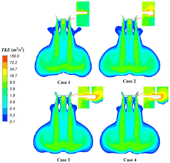
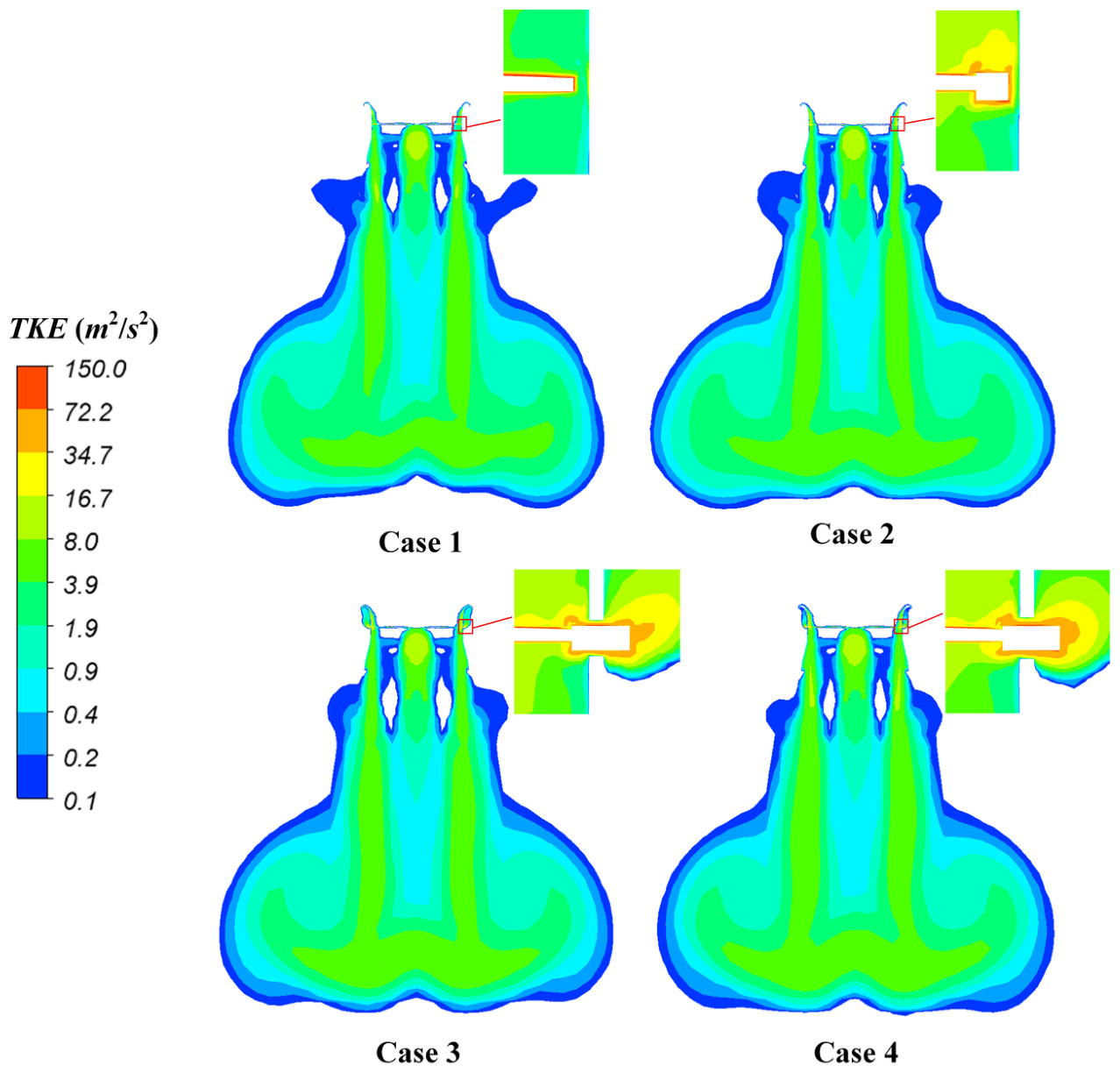
The changes in clearance flow topology and vortex coherence identified in Section 3.2 affect the distribution of modeled turbulence and time-averaged aerodynamic loading near the blade tip. Figure 6 compares the modeled TKE in the rotor midplane for Cases 1–4. It should be noted that the TKE obtained from the URANS calculation is a turbulence-model quantity rather than directly resolved fluctuation energy.
Figure 6.
Distributions of modeled TKE in the rotor midplane for Cases 1–4.
The TKE contours are presented using a logarithmic color scale, with values below 0.1 m2/s2 blanked to highlight the principal high shear regions. In all configurations, the highest modeled TKE is concentrated near the blade tip clearance. Case 2 exhibits the largest peak value of approximately 143 m2/s2, indicating strong shear within the retained radial gap between the rotating ring and the stationary duct. This result is consistent with the higher torque and lower figure of merit reported in Section 3.1.
For the WPBR configurations, the peak modeled TKE decreases to approximately 102 m2/s2 in Case 3 and 99 m2/s2 in Case 4. Meanwhile, moderate TKE is distributed over a broader region within the annular duct-wall cavity. This pattern indicates that the concentrated shear associated with the conventional radial leakage jet is redistributed through the axial clearances and cavity flow. However, the lower peak value should not be interpreted as direct quantitative evidence of total turbulent-energy dissipation or broadband-noise reduction.
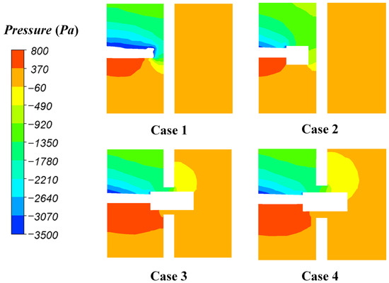
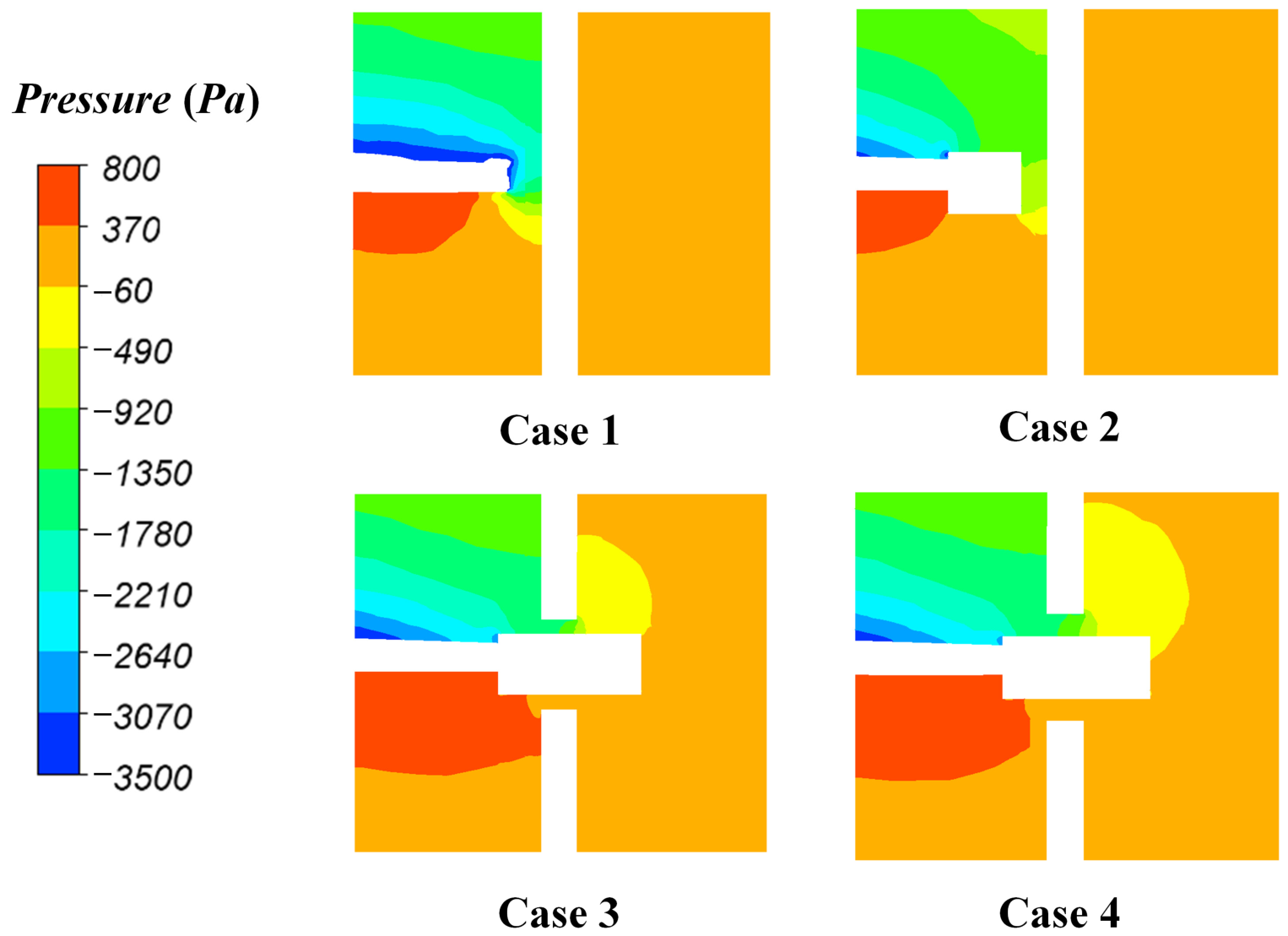
The corresponding time-averaged static pressure distributions are shown in Figure 7. In Case 1, a localized suction region below approximately −3500 Pa appears near the blade tip suction surface. The resulting pressure difference across the blade tip drives the concentrated radial leakage flow observed in Figure 3. In Case 2, the suction peak is moderately reduced, but the retained radial clearance continues to sustain a cross-clearance pressure gradient around the internal ring.
Figure 7.
Time-averaged static pressure distributions in the blade tip and clearance regions for Cases 1–4.
The WPBR configurations exhibit a substantially different near wall pressure distribution. The outward leakage flow and its return through the annular cavity generate a localized high-pressure stagnation region beneath the blade ring, with pressure values of approximately 370–800 Pa. This pressure accumulation reflects the blockage and momentum exchange associated with the U-shaped recirculation and contributes to the redistribution of aerodynamic loading near the blade tip. As the axial clearance increases from Case 3 to Case 4, the enlarged flow exchange through the cavity modifies this loading distribution while reducing the total thrust, consistent with the trend reported in Section 3.1.
Sharp pressure gradients remain near the axial clearance edges, where the returning cavity flow interacts with the main passage. These regions may contribute to variations in unsteady surface loading. Nevertheless, the time-averaged pressure contours alone do not quantify wall pressure fluctuations or acoustic-source strength. The resulting tonal components, overall sound-pressure levels, and spatial directivity predicted using the URANS-FW-H method are therefore examined separately in Section 3.4.
3.4. Aeroacoustic Characteristics and Directivity
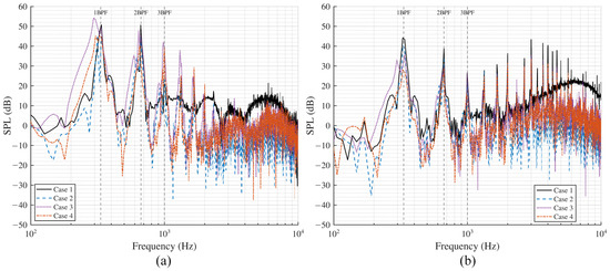
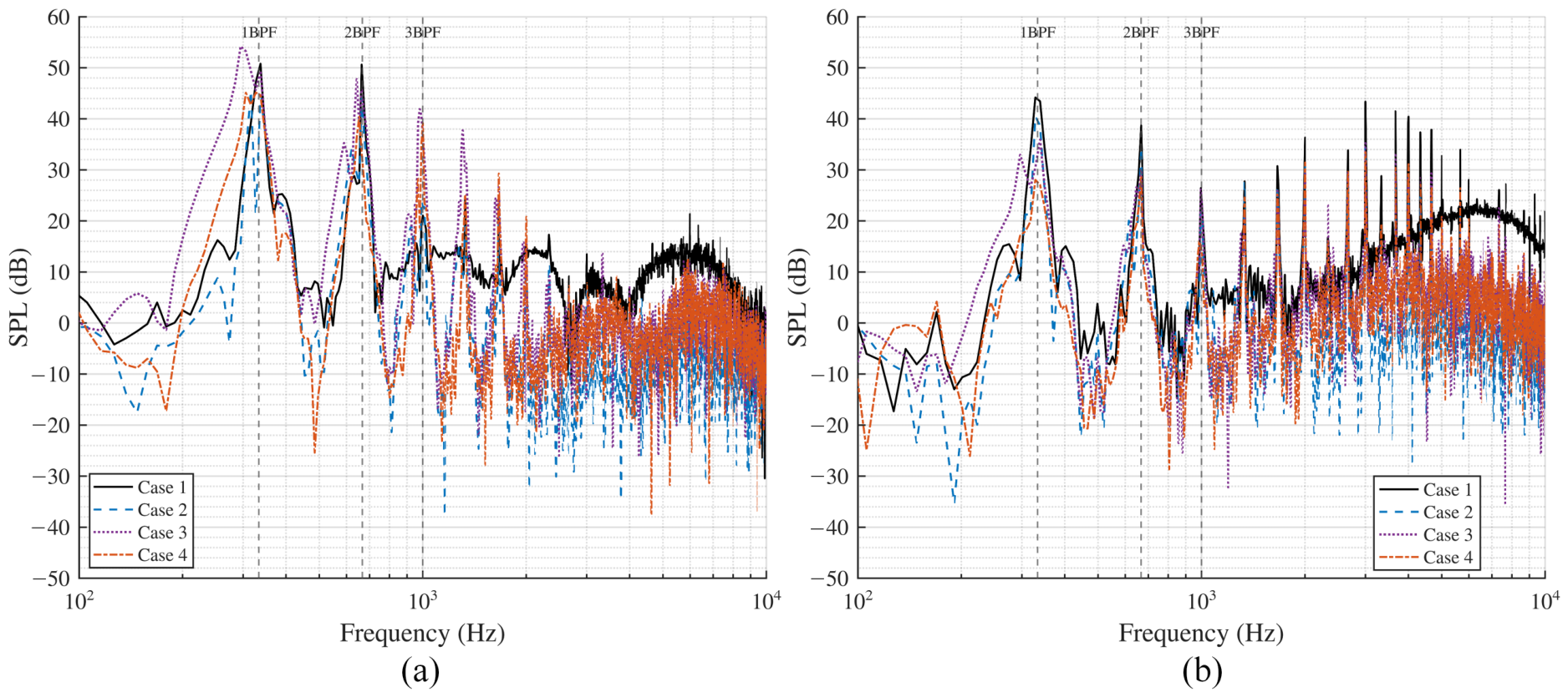
The predicted acoustic characteristics of Cases 1–4 are compared using the 13 virtual observers defined in Section 2.2. Two representative observers are selected for spectral analysis: the inlet-side observer at θ = 0° and the rotor-plane observer at θ = 90°. Figure 8 presents the SPL spectra at these two locations. All spectra are shown without vertical offsets to allow direct comparison among the configurations.
Figure 8.
Predicted sound pressure level spectra for Cases 1–4 at (a) the inlet-side observer (θ = 0°) and (b) the rotor-plane observer (θ = 90°).
The sampling-duration sensitivity of the dominant tonal response was assessed using the terminal portions of the existing FW-H receiver histories. At the representative 90° rotor-plane observer, the 1BPF harmonic amplitude varied by less than approximately 0.7 dB when terminal sampling windows of two, four, and six rotor revolutions were considered for Cases 1 and 4. In particular, extending the terminal sampling window from four to six revolutions changed the 1BPF harmonic amplitude by approximately 0.3 dB for Case 1 and 0.1 dB for Case 4. These relatively small variations indicate that the dominant tonal response in the terminal portion of the sampled record was sufficiently stable for the comparative acoustic analysis presented below.
All configurations exhibit distinct peaks at the BPF of 333.3 Hz and its harmonics, indicating that periodic blade loading is an important component of the predicted acoustic field. The differences between the inlet-side and rotor plane spectra further demonstrate the directional dependence of the predicted acoustic radiation, although these differences alone do not establish a single dominant acoustic source mechanism.
The axial clearance size modifies both the magnitude and distribution of the predicted tonal components. At the inlet-side observer (θ = 0°), the predicted 1BPF level decreases from 50.80 dB in Case 1 to 49.38 dB in Case 3 and 44.64 dB in Case 4. Thus, increasing the single-sided axial clearance from 0.8 to 1.2 mm reduces the predicted 1BPF level by approximately 4.74 dB. Relative to Case 1, Case 4 provides predicted reductions of approximately 6.16 and 17.17 dB at 1BPF and 2BPF, respectively. However, its predicted 3BPF level increases from 21.05 to 39.14 dB. The predictions, therefore, indicate that the axial clearance topology redistributes tonal energy among the blade-passing harmonics rather than uniformly suppressing all tonal components.
At the rotor plane observer (θ = 90°), Case 4 yields predicted SPL values of 27.08, 28.56, and 14.78 dB at 1BPF, 2BPF, and 3BPF, respectively. Relative to Case 1, these values correspond to predicted reductions of approximately 16.36, 10.13, and 11.67 dB. The reduction across the first three blade-passing harmonics is, therefore, more consistent at the rotor plane observer than at the inlet side observer. The altered clearance flow path, reduced near-field concentration and downstream redistribution of the tip-region vortical structures, and duct-wall cavity may jointly contribute to this directional change in the predicted tonal radiation. The predicted 1BPF difference is substantially larger than the sampling-related variation identified above; however, its absolute magnitude remains unvalidated experimentally at the 5000 r/min design condition.
Differences are also observed above approximately 2 kHz. Case 1 exhibits a broad spectral elevation over part of the resolved high frequency range, whereas Case 4 generally shows lower predicted levels over the same range. This trend is qualitatively consistent with the redistribution of the leakage flow and the reduced near-field concentration and altered downstream organization of the vortical structures discussed in Section 3.2 and Section 3.3. However, because the small-scale turbulent fluctuations are modeled rather than fully resolved within the URANS framework, these high frequency differences are interpreted as comparative predictions rather than quantitatively validated broadband noise reductions.
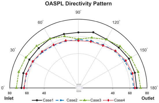
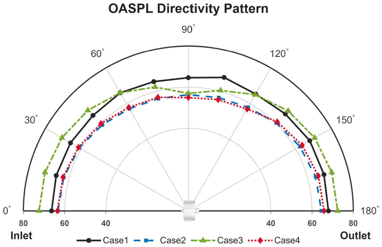
The OASPL directivity calculated from the 13 observers is presented in Figure 9. The same frequency range and signal processing settings are used for all configurations.
Figure 9.
Predicted OASPL directivity at a radius of 1.0 m for Cases 1–4.
Using the same integrated frequency range and signal processing settings, Case 1 exhibits relatively high predicted OASPL values in the rotor plane and downstream sectors, particularly over approximately θ = 90–120°. Case 3 shows increased acoustic levels in several directions, indicating that the narrowest axial clearance does not provide a consistent acoustic benefit. By comparison, Case 4 exhibits generally lower predicted OASPL values over the observer arc and provides a maximum predicted reduction of approximately 15 dB near the rotor plane observer relative to Case 1.
The acoustic comparison is limited to Cases 1–4. Within the two WPBR configurations examined acoustically, Case 4 exhibits the more favorable response. Case 3 yields higher predicted OASPL values in several directions, whereas Case 4 generally yields lower predicted OASPL values over the observer arc and lower predicted levels of the first three BPF components at the rotor-plane observer relative to Case 1. Combined with its modest thrust benefit over Case 1 and its lower torque than Case 3, Case 4 is treated as a representative thrust–torque–noise compromise. This designation does not imply a global optimum over the full clearance range because Cases 5 and 6 were not evaluated acoustically and the figure of merit of Case 4 remains below that of Case 1. The predicted broadband and absolute OASPL differences require further validation using turbulence-resolving simulations or high-speed acoustic experiments.
Although Case 4 is selected based on its balance among thrust, torque, and predicted acoustic response, practical implementation of the WPBR configuration also requires stable non-contact support of the penetrating blade ring. Section 4 therefore examines the preliminary structural implications and low-speed feasibility of the magnetic support architecture. At the propulsion-unit level, these predicted results indicate that axial clearance can be used to balance thrust, torque, and tonal radiation in ducted fans intended for unmanned eVTOL aircraft. Whole-aircraft acoustic performance will require further evaluation of installation and multiple-propulsor effects.
4. Preliminary Structural Assessment and Low-Speed Feasibility Demonstration
The structural and prototype assessments are intended to evaluate the support architecture of an unmanned eVTOL propulsion unit rather than a complete aircraft system. The WPBR configuration requires a non-contact support system to prevent contact between the rotating blade ring and the stationary duct sections. This section presents a low-speed prototype demonstration and a preliminary prestressed modal assessment of the magnetically supported rotor. The 2000 r/min test is included only to demonstrate the physical realization and low-speed operability of the magnetically supported architecture; aerodynamic and acoustic measurements at this operating condition are outside the scope of the present study.
4.1. Prototype Setup and Low-Speed Operational Demonstration
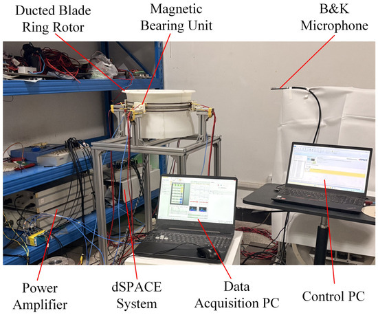
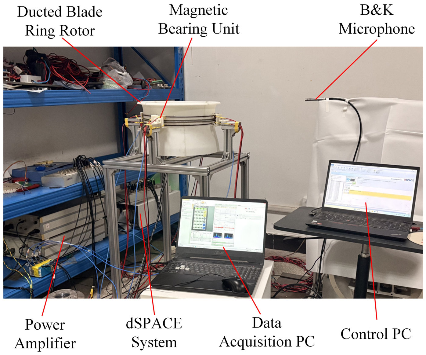
A laboratory prototype was constructed to examine the physical realization and low-speed operability of the magnetically supported blade ring concept. As shown in Figure 10, the experimental platform consisted of the ducted blade ring rotor, magnetic-bearing units, power amplifiers, a dSPACE real-time control system (dSPACE Group SE & Co. KG, Paderborn, Germany), displacement sensing and signal conditioning components, a Brüel & Kjær microphone (Hottinger Brüel & Kjær A/S, Virum, Denmark), a data-acquisition computer, and a separate control computer. The platform integrates the rotating prototype, magnetic support system, real-time controller, and measurement equipment within a complete laboratory setup.
Figure 10.
Laboratory prototype and integrated control and measurement platform for the magnetically supported ducted blade ring rotor.
The magnetic actuators provided noncontact support forces to the outer blade ring, while the dSPACE system regulated the actuator currents using the measured displacement signals. Controlled rotation was achieved at up to 2000 r/min, demonstrating integrated operation of the rotor, displacement sensors, power amplifiers, controller, and magnetic actuators. The test speed was limited by the strength, manufacturing accuracy, dynamic balance, and assembly reliability of the additively manufactured rotor. Reaching the numerical design condition of 5000 r/min will require a higher-strength, dynamically balanced rotor together with improved manufacturing and assembly accuracy. Accordingly, the experiment is interpreted as a low-speed feasibility demonstration of the support architecture for the intended unmanned eVTOL propulsion concept, rather than as quantitative validation of the aerodynamic or aeroacoustic predictions at 5000 r/min. A key limitation of the present study is therefore the absence of matched thrust and torque measurements at or near the 5000 r/min design condition. Consequently, the high-speed aerodynamic performance reported in Section 3 should be regarded as numerical predictions rather than experimentally validated performance. Design-speed validation will require a higher-strength, accurately manufactured and dynamically balanced rotor together with dedicated thrust/torque measurements under matched operating conditions.
4.2. Prestressed Modal Analysis
A prestressed modal analysis was conducted to provide a preliminary assessment of the structural dynamic characteristics of the rotating configurations at the nominal speed of 5000 r/min. Centrifugal prestress and the associated stress-stiffening effect were included before extracting the natural frequencies. The calculated modal frequencies were compared with the rotational frequency (1P = 83.3 Hz) and the BPF (333.3 Hz), which represent two principal periodic excitation frequencies of the four-bladed rotor.
The structural model represents the intended high-speed carbon-fiber-composite rotor rather than the additively manufactured low-speed prototype described in Section 4.1. The numerical design rotor was modeled using an equivalent isotropic carbon fiber composite with an elastic modulus of 65 GPa, a Poisson’s ratio of 0.31, and a density of 1500 kg/m3. For Cases 1 and 2, the hub interface was fixed, while no additional support was applied to the blade tip or outer-ring region. For the WPBR configurations, the hub was fixed and the magnetic-bearing action on the outer ring was represented by an equivalent distributed elastic support, as illustrated in Figure 11.
Figure 11.
Structural boundary conditions and equivalent magnetic support representation of the WPBR rotor used in the prestressed modal analysis.
A normal foundation stiffness of 0.01949 N/mm3 was applied to the supported outer ring surface. This equivalent stiffness was obtained by linearizing the magnetic restoring force around the nominal operating gap of 0.5 mm and represents the local support effect of the active magnetic-bearing system. Both Cases 3 and 4 were included in the structural analysis. Because they share the same rotating structural geometry and equivalent magnetic support condition, they yield identical modal frequencies. Cases 5 and 6 were not analyzed separately; however, because their rotating structures and support conditions are the same as those used for Cases 3 and 4, their modal characteristics are expected to be identical within the assumptions of the present structural model. The first six prestressed natural frequencies of Cases 1–4 are summarized in Table 5.
Table 5.
First six prestressed natural frequencies of Cases 1–4 at 5000 r/min.
The first four modes of Case 1 are closely clustered around 102.7 Hz. Inspection of the computed mode shapes indicates that these modes are primarily associated with blade bending. Their frequencies are approximately 23% higher than the 1P excitation frequency at 5000 r/min. Although no direct frequency coincidence occurs at the nominal speed, the close modal clustering may increase the sensitivity of the rotor response to structural asymmetry and unsteady aerodynamic loading.
Adding the unsupported internal blade ring in Case 2 reduces the first natural frequency to 70.69 Hz. The added ring mass and the absence of an external tip support introduce a ring-dominated global deformation mode. Because this frequency is lower than the 1P frequency at the nominal speed, a frequency crossing may occur during rotor acceleration or deceleration. The modal result therefore indicates a potential acceleration or deceleration resonance concern, but it does not by itself demonstrate a steady-state resonance at 5000 r/min.
The equivalent magnetic support in the WPBR configurations changes the structural boundary condition and increases the first natural frequency to 141.91 Hz, approximately 70% above the nominal 1P frequency. The remaining calculated modes are more widely distributed between 191.54 and 294.37 Hz. None of the first six modes coincides directly with either 1P or BPF at 5000 r/min. However, comparison at the nominal rotational speed alone does not exclude possible frequency crossings during rotor acceleration. Therefore, a speed-dependent Campbell analysis was further performed to examine the evolution of the modal frequencies relative to the 1P and 4P excitation lines over the operating-speed range.
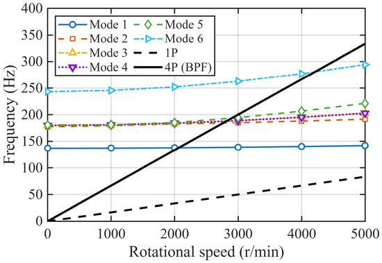
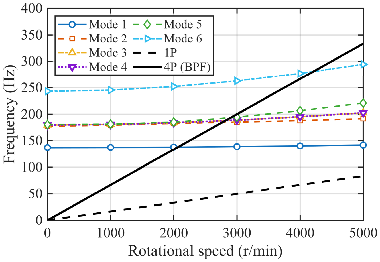
To further assess possible frequency crossings during rotor acceleration, a speed-dependent Campbell diagram was constructed for the WPBR rotor using the same prestressed structural model and equivalent magnetic-support condition. Because Cases 3 and 4 share the same rotating structural geometry and support condition, they exhibit identical modal characteristics. The first six natural frequencies were evaluated from 0 to 5000 r/min at intervals of 1000 r/min and compared with the 1P rotational-frequency and 4P blade-passing frequency excitation lines.
As shown in Figure 12, the first six natural frequencies increase gradually with rotational speed, indicating the centrifugal-stiffening effect captured by the prestressed structural model. The 1P excitation remains below the first natural-frequency branch throughout the investigated speed range and therefore exhibits no frequency crossing up to 5000 r/min. In contrast, the 4P excitation line crosses the first five modal branches within approximately 2100–2900 r/min and crosses the sixth modal branch at approximately 4210 r/min. These intersections identify potential frequency-crossing regions during rotor acceleration rather than confirmed resonances, because the present analysis does not include forced-response amplitudes, structural damping, or the complete speed-dependent magnetic-bearing control dynamics.
Figure 12.
Speed-dependent Campbell diagram of the magnetically supported WPBR rotor (Cases 3 and 4).
The results indicate that the elastic support shifts low-frequency modal behavior associated with the unsupported internal ring and substantially alters the modal distribution of the rotor. Nevertheless, the present analysis is limited to a linear prestressed modal model with an equivalent magnetic support stiffness. It does not include the complete speed-dependent magnetic-bearing control dynamics, gyroscopic coupling, structural damping, actuator saturation, assembly tolerances, or possible rotor duct contact. Although the Campbell diagram identifies potential frequency-crossing regions during rotor acceleration, harmonic-response analysis and high-speed experimental characterization are still required to quantify the associated vibration amplitudes and to confirm resonance avoidance and structural stability.
Compared with the conventional configuration, the WPBR relocates the rotor–duct clearance from the main flow passage to axial end-face gaps within the duct-wall, thereby providing an additional means of controlling the clearance-flow path and acoustic radiation. The representative 1.2 mm WPBR case retains a modest thrust increase while showing lower predicted tonal and overall sound levels in important observer directions. In addition, the penetrating outer ring enables non-contact magnetic support and provides potential for future active clearance and vibration control. These features may be relevant to compact unmanned eVTOL propulsion, although the present WPBR does not provide an overall efficiency improvement relative to the conventional baseline.
5. Conclusions
This study investigated a wall-penetrating blade ring ducted fan in which the conventional radial tip clearance was replaced by equal upper and lower axial end face clearances. A conventional ducted fan, an internal blade ring configuration, and four WPBR configurations with single-sided axial clearances of 0.8–2.0 mm were compared under the same quasi-hover condition at 5000 r/min using sliding-mesh URANS simulations coupled with the FW-H formulation.
The numerical results showed a clear trade-off among thrust, torque, and predicted acoustic radiation. The 0.8 mm configuration generated the highest thrust of 30.250 N but also the highest torque of 0.870 N·m. Increasing the clearance to 1.2 mm reduced the torque by approximately 6.1% relative to the 0.8 mm case while retaining a thrust of 28.724 N, approximately 2.1% above the conventional baseline. Its figure of merit remained below the baseline value; therefore, the 1.2 mm configuration is not regarded as an aerodynamic optimum. Instead, it is used as a representative compromise among thrust, torque, and predicted acoustic response between the two WPBR configurations examined in detail acoustically.
The WPBR topology redirected the clearance flow through the annular duct-wall cavity and formed a U-shaped recirculation path between the lower and upper axial clearances. Compared with the continuous TLV in the conventional configuration, the WPBR cases exhibited shorter and less spatially coherent vortical structures within approximately 0.8 local blade-tip chord lengths from the blade region. The peak modeled TKE was reduced and distributed over a broader cavity region, while the maximum local velocity decreased from approximately 127 m/s in Case 1 to 118 m/s in Case 4. These results indicate a redistribution and weakening of the concentrated leakage jet, although the present URANS results do not quantitatively confirm a canonical vortex breakdown mode.
The URANS-FW-H results predicted a reduction of approximately 16.4 dB in the 1BPF level at the rotor-plane observer relative to the conventional baseline and a maximum OASPL reduction of approximately 15 dB near the rotor plane. These predictions indicate changes in tonal radiation and acoustic directivity rather than uniform suppression at all harmonics and observer locations. Because the small-scale turbulent fluctuations were modeled rather than fully resolved, the high-frequency and absolute OASPL differences are interpreted as comparative numerical trends.
The preliminary modal assessment showed that the equivalent outer ring magnetic support substantially modified the modal distribution of the intended carbon fiber composite rotor. The additively manufactured prototype achieved controlled contactless rotation at up to 2000 r/min, demonstrating system integration and low-speed operability of the support architecture for the proposed unmanned eVTOL propulsion concept. However, the present prototype does not provide quantitative validation of the numerical predictions at the 5000 r/min design condition. The absence of matched thrust and torque measurements at or near 5000 r/min therefore remains a key limitation of the present study, and the reported high-speed aerodynamic performance should be interpreted as numerical predictions rather than experimentally validated values. Future work will focus on aerodynamic, aeroacoustic, and structural validation at the design speed using a higher-strength, dynamically balanced carbon-fiber rotor, together with further investigation of active vibration and axial-clearance control using the active magnetic suspension system. Overall, the present results provide a propulsion-unit-level basis for further development of magnetically supported ducted fans for unmanned eVTOL aircraft.
Author Contributions
Conceptualization, Q.L. and M.Z.; methodology, Q.L. and M.Z.; software, Q.L.; validation, Q.L.; formal analysis, C.H.; investigation, C.H.; resources, Y.H.; data curation, Q.L.; writing—original draft preparation, Q.L.; writing—review and editing, Y.H. and M.Z.; visualization, Q.L.; supervision, Y.H.; project administration, Y.H.; funding acquisition, Y.H. All authors have read and agreed to the published version of the manuscript.
Funding
Q.L. was supported by the China Scholarship Council. This research also received financial support from research funds administered by Y.H. at Wuhan University of Technology.
Data Availability Statement
The data presented in this study are available on request.
Acknowledgments
The authors acknowledge Wuhan University of Technology and the National University of Singapore for providing access to research facilities, institutional support, and technical assistance during this work.
Conflicts of Interest
The authors declare no conflicts of interest.
References
- Liu, Y. Multi-fidelity Optimization of Ducted Fan for eVTOL Aircraft. In Proceedings of the AIAA AVIATION 2023 Forum, San Diego, CA, USA, 12–16 June 2023; p. 4393. [Google Scholar]
- Goodson, K.; Grunwald, K. Aerodynamic Loads on an Isolated Shrouded-Propeller Configuration for Angles of Attack from-10 Deg to 110 Deg; NASA: Washington, DC, USA, 1962.
- Shang, W.; Li, D.; Luo, K.; Fan, J.; Liu, J. Effects of tip clearance size on vortical structures and turbulence statistics in tip-leakage flows: A direct numerical simulation study. Phys. Fluids 2021, 33, 085127. [Google Scholar] [CrossRef] [Scilit]
- Liberatori, J.; Valorani, M.; Ciottoli, P.P. Anisotropy analysis of vortex breakdown states via direct numerical simulation. Int. J. Heat Fluid Flow 2024, 109, 109531. [Google Scholar] [CrossRef] [Scilit]
- Seki, R.; Azuma, T.; Iwatani, J.; Nakaniwa, A.; Okui, H.; Shibata, T. Investigation of tip leakage vortex breakdown in a high-speed multistage axial compressor. J. Turbomach. 2023, 145, 071017. [Google Scholar] [CrossRef] [Scilit]
- Liu, Y.; Zhong, W.; Zhong, L.; Tang, Y. Comparison of vortex identification criteria for tip leakage flow in an axial compressor rotor. Aerosp. Sci. Technol. 2025, 168, 110840. [Google Scholar] [CrossRef] [Scilit]
- Cao, Z.; Gao, X.; Yang, J.; Wang, C.; Liu, B. Interaction mechanism between incoming vortex and tip leakage vortex breakdown of a compressor cascade. Phys. Fluids 2023, 35, 096102. [Google Scholar] [CrossRef] [Scilit]
- Gao, X.; Cao, Z.; Liu, B. RANS investigation of incoming vortex on the tip leakage vortex breakdown in an aspirated compressor cascade. Int. J. Heat Fluid Flow 2025, 114, 109796. [Google Scholar] [CrossRef] [Scilit]
- Wang, T.; Xuan, Y.; Han, X. The effects of stator-rotor interaction on unsteady characteristics of turbine tip leakage flow. Aerosp. Sci. Technol. 2023, 141, 108544. [Google Scholar] [CrossRef] [Scilit]
- Yang, F.; Wu, Y.; Chen, Z.; Spence, S.; Li, B. The unsteadiness of tip leakage vortex breakdown and its role in rotating instability. Phys. Fluids 2023, 35, 0169353. [Google Scholar] [CrossRef] [Scilit]
- Yang, F.; Wu, Y.; Spence, S.; Li, B.; Chen, Z. The investigation on vortex breakdown prior to stall in a compressor rotor with non-uniform tip clearance. Phys. Fluids 2024, 36, 0223835. [Google Scholar] [CrossRef] [Scilit]
- Li, J.; Qiang, X.; Teng, J.; Zhu, M.; Lu, S. Comparison of turbulence models for tip leakage flow of a large clearance compressor cascade with casing motion. Aerosp. Sci. Technol. 2025, 166, 110545. [Google Scholar] [CrossRef] [Scilit]
- Cao, Z.; Li, Z.; Yang, J.; Gu, Q.; Gao, X.; Yang, N.; Liu, B. Influence of circumferential casing treatment groove on leakage vortex breakdown and unsteady flow characteristics in a transonic compressor rotor. Aerosp. Sci. Technol. 2025, 168, 110992. [Google Scholar] [CrossRef] [Scilit]
- Zhang, X.; Wu, Y.; Zhang, Z.; Wang, D.; Liu, C. Vortex Breakdown Suppression in a Compressor Cascade Using an L-shaped Groove via Flow Deflection. Aerosp. Sci. Technol. 2026, 172, 111709. [Google Scholar] [CrossRef] [Scilit]
- Medzorian, J.R.; Lynch, S.P. Effect of Freestream Turbulence on Wall-Bounded Tip Vortex Breakdown and Decay Mechanisms. In Proceedings of the AIAA SCITECH 2023 Forum, National Harbor, MD, USA, 23–27 January 2023; p. 2484. [Google Scholar]
- Stack, C.M.; Barone, M.F.; Wagnild, R.; Fisher, T. Wall pressure fluctuation prediction for high-speed flows via wall-modeled large-eddy simulation. In Proceedings of the AIAA SCITECH 2025 Forum, Orlando, FL, USA, 6–10 January 2025; p. 2589. [Google Scholar]
- Hahn, C.J.; Wolek, A.; Misar, A.S.; Uddin, M. Characterizing Vortex Ring State During UAV Landing on a Ground Vehicle Using CFD. In Proceedings of the AIAA SCITECH 2025 Forum, Orlando, FL, USA, 6–10 January 2025; p. 1686. [Google Scholar]
- Ozturk, I.; Sezer-Uzol, N. Aerodynamic Investigation of Hover Using Vortex Ring Wake Model and Free Vortex Wake Model. In Proceedings of the AIAA SCITECH 2025 Forum, Orlando, FL, USA, 6–10 January 2025; p. 2027. [Google Scholar]
- Cantos, S.; Zhou, P.; Wu, H.; Ma, Z.; Chen, W.; Zhong, S.; Zhang, X. Aerodynamics and aeroacoustics of ducted propellers: A study on the design and geometry effects. Phys. Fluids 2024, 36, 0191323. [Google Scholar] [CrossRef] [Scilit]
- Goudswaard, R.J.; Ragni, D.; Baars, W.J. Effects of the rotor tip gap on the aerodynamic and aeroacoustic performance of a ducted rotor in hover. Aerosp. Sci. Technol. 2024, 155, 109734. [Google Scholar] [CrossRef] [Scilit]
- Hu, Y.; Chao Zhang, X.; Qiang Wang, G.; Zhang, X.P.; Li, H.Z. Hovering efficiency optimization of ducted propeller with large blade tip clearance based on grooved duct configuration. Aerosp. Sci. Technol. 2024, 150, 109226. [Google Scholar] [CrossRef] [Scilit]
- Canepa, E.; Cattanei, A.; Zecchin, F.M.; Parodi, D. Large-scale unsteady flow structures in the leakage flow of a low-speed axial fan with rotating shroud. Exp. Therm. Fluid Sci. 2019, 102, 1–19. [Google Scholar] [CrossRef] [Scilit]
- Pereira, M.; Ravelet, F.; Azzouz, K.; Azzam, T.; Oualli, H.; Kouidri, S.; Bakir, F. Improved aerodynamics of a hollow-blade axial flow fan by controlling the leakage flow rate by air injection at the rotating shroud. Entropy 2021, 23, 877. [Google Scholar] [CrossRef] [Scilit]
- Wang, K.; Huang, H.-X.; Tan, H.-J.; Lin, Z.-K.; Tang, X.-B.; Cheng, T. Impact of shape factors on flow dynamics and performance in boundary layer ingesting inlet. Aerosp. Sci. Technol. 2025, 157, 109829. [Google Scholar] [CrossRef] [Scilit]
- Ahmed, F.; Ramos-Romero, C.A.; Torija Martinez, A.J.; Azarpeyvand, M. Boundary layer ingestion ducted fan: Aeroacoustic and psychoacoustic insights. In Proceedings of the 30th AIAA/CEAS Aeroacoustics Conference, Rome, Italy, 4–7 June 2024; p. 3379. [Google Scholar]
- Moghadam, S.M.A.; Loosen, S.; Meinke, M.; Schröder, W. Reduced-order analysis of the acoustic near field of a ducted axial fan. Int. J. Heat Fluid Flow 2020, 85, 108657. [Google Scholar] [CrossRef] [Scilit]
- Miller, K.; Morata, D.; Papamoschou, D. Investigation of the Near Acoustic Field of a Ducted Fan. In Proceedings of the AIAA AVIATION 2023 Forum, San Diego, CA, USA, 12–16 June 2023; p. 3514. [Google Scholar]
- Hirono, F.C.; Torija, A.J.; Grimshaw, S.D.; Cousins, D.; Farman, J.; Taylor, J.V. Aerodynamic and aeroacoustic design of electric ducted fans. Aerosp. Sci. Technol. 2024, 153, 109411. [Google Scholar] [CrossRef] [Scilit]
- Ali, M.M.; Iftikhar, H.; Khan, A.; Zain, M.; Azim, R.A.; Talha, T.; Akhtar, I. A Numerical Investigation of Aerodynamic and Aeroacoustic Performance of Aerial Screw Propeller for Small UAVs and VTOL. Aerosp. Sci. Technol. 2026, 172, 111732. [Google Scholar] [CrossRef] [Scilit]
- Zheng, S.; Wang, C. Rotor balancing for magnetically levitated TMPs integrated with vibration self-sensing of magnetic bearings. IEEE/ASME Trans. Mechatron. 2021, 26, 3031–3039. [Google Scholar] [CrossRef] [Scilit]
- Wei, S.; Le, Y.; Zhou, J.; Yin, Y.; Zhang, D.; Zheng, S. Stability control of high-speed magnetic levitation turbomolecular pumps with shock-excited disturbance. ISA Trans. 2023, 142, 585–593. [Google Scholar] [CrossRef] [Scilit]



Disclaimer/Publisher’s Note: The statements, opinions and data contained in all publications are solely those of the individual author(s) and contributor(s) and not of MDPI and/or the editor(s). MDPI and/or the editor(s) disclaim responsibility for any injury to people or property resulting from any ideas, methods, instructions or products referred to in the content. |
© 2026 by the authors. Licensee MDPI, Basel, Switzerland. This article is an open access article distributed under the terms and conditions of the Creative Commons Attribution (CC BY) license.