


Abstract
Focusing on the complex aerodynamic interference and attitude response during multibody separation in the low-pressure and low-density environment of near space, a numerical investigation of the effects of different initial separation conditions on submunition motion is conducted. A three-dimensional unsteady flow model is established by coupling the six-degree-of-freedom rigid-body equations with the overset mesh technique. The effects of the free stream Mach number, initial angle of attack, initial separation velocity, and separation altitude on the motion characteristics of the submunition are systematically analyzed. The results show that, compared with conventional low-altitude conditions, aerodynamic forces have a weaker corrective effect on the separation motion and attitude in near space, making the initial separation parameters more influential. Increasing the free stream Mach number and initial angle of attack enhances the radial separation capability but intensifies the attitude response. As the separation altitude increases, the aerodynamic forces weaken, and the displacement and attitude variations in the submunition decrease accordingly. The initial axial separation velocity Vx0 has relatively little influence on the radial separation distance and pitching response. Increasing the initial radial separation velocity Vy0 increases the radial separation distance and reduces pitch oscillations, whereas increasing the magnitude of the initial lateral separation velocity significantly amplifies the roll and yaw responses. The results provide a reference for the design of initial parameters for multi-body separation systems operating in near space.
1. Introduction
With the development of long-range precision-strike weapons and high-altitude, high-speed vehicles, multi-body separation operations have gradually extended from the dense atmosphere to near space. Near space generally refers to the atmospheric region at altitudes of approximately 20–100 km, between the conventional operating airspace of aircraft and satellite orbits [1].
Multi-body separation is a complex dynamic process in which multiple rigid bodies transition from a mechanically connected state to mutually independent motion during flight. It is an important topic in modern aerospace vehicle design and is commonly encountered in internal weapon release [2], two-stage-to-orbit vehicle separation [3,4], cluster munition dispensing, fairing separation, and ejection-seat deployment [5]. At the onset of separation, strongly unsteady flow evolution and complex aerodynamic interference occur between the separating bodies, including shock-wave interactions [6] and the evolution of separation vortices in the wake [7]. During separation, complex flow structures, such as shock waves, separation vortices, and shear layers, evolve continuously with the relative motion between the submunition and the carrier. These changes redistribute the aerodynamic loads over the bodies and induce attitude variations. In turn, variations in body attitude modify the surrounding flow structures and further alter the surface aerodynamic load distribution.
Multi-body separation in near space involves not only high-speed compressible effects, flow separation, and multi-physics coupling, but also the influence of the low-density, high-altitude environment. Consequently, its aerodynamic characteristics differ markedly from those under dense-atmosphere conditions [8,9,10]. Improper initial separation parameters may lead to large attitude disturbances of the submunition and may even result in collision with the carrier. Therefore, investigating the effects of different initial separation conditions on multi-body separation in near space, and predicting the post-release trajectory and attitude of the submunition, are important for improving separation safety and supporting the design of initial separation parameters.
Extensive studies have been conducted on complex flow field interference during multi-body separation. Wind tunnel testing provides a direct means of reproducing the aerodynamic interactions between separating bodies. Panneerselvam S et al. [11] investigated the aerodynamic interference between a carrier and a submunition through wind-tunnel experiments. Woods et al. [12] examined the stage-separation aerodynamics of the Hyper-X vehicle under near-space conditions and provided experimental data for the analysis of hypersonic multi-body separation. When aerodynamic and dynamic similarity requirements are satisfied, wind-tunnel tests can be combined with high-speed photography to capture separation trajectories and obtain the displacement and attitude responses of the separating bodies [13,14,15,16]. However, wind tunnel testing is limited by the difficulty of simultaneously satisfying all similarity requirements, as well as by its relatively high cost and long experimental cycle. Consequently, computational fluid dynamics has gradually become an important tool for investigating multi-body separation. Koomullil et al. [17] developed a computational framework coupling the overset mesh method with six-degree-of-freedom rigid-body dynamics, enabling the simultaneous solution of the unsteady flow field, aerodynamic loads, and rigid-body motion. Zhang et al. [18] applied the overset mesh method to the numerical simulation of supersonic cluster munition separation and demonstrated its capability to capture the complex disturbed flow field arising during the separation process. Tian et al. [19] further coupled unstructured overset meshes, six-degree-of-freedom equations of motion, and a rigid-body collision model to simulate the simultaneous motion and mutual collisions of multiple separating bodies. These studies demonstrate that the coupled overset mesh and six-degree-of-freedom approach is capable of handling large relative displacements and complex aerodynamic interference during multi-body separation, thereby providing a methodological basis for the numerical approach adopted in the present study.
With the progressive improvement in the understanding of carrier–submunition separation flows, it has been recognized that the aerodynamic coupling between the carrier and the submunition depends not only on the flow-field structure but also strongly on the initial separation conditions. Accordingly, considerable attention has been devoted to the effects of initial separation parameters on the attitude evolution of the submunition. Panagiotopoulos et al. [20] employed computational fluid dynamics to investigate the flow structures and trajectories of an externally carried store released at different angles of attack. Wang et al. [21] coupled the Arbitrary Lagrangian–Eulerian (ALE) method with a six-degree-of-freedom motion model to examine the effects of the initial separation velocity and initial attitude angle on the separation dynamics of a carrier–submunition system. Chu and Li [22] conducted numerical simulations of a three-stage separation process and found that an excessively large initial attitude angle was unfavorable for stable flight after deployment, whereas appropriate matching of the initial separation velocity and the addition of a baffle structure could improve separation stability. Other studies have examined the effects of key variables, including Mach number, flight altitude, dynamic pressure, and ejection force, on the separation trajectory, and have further explored efficient approaches for reducing the computational cost of large-scale parametric simulations [23,24,25].
Considerable progress has been made in experimental and numerical investigations of multi-body separation. Previous studies have examined the effects of parameters such as the freestream Mach number, initial angle of attack, and radial ejection velocity on the separation process. However, for airbag-driven dispensing, the airbag ideally provides an ejection force predominantly along the prescribed radial separation direction, whereas during the actual ejection process, nonuniform deformation of the airbag and variations in the contact state between the airbag and the submunition may alter the magnitude and direction of the resultant force. Consequently, the actual release state may deviate from the ideal radial separation condition, leading to variations in the axial, radial, and lateral components of the initial separation velocity. Therefore, the three initial velocity components Vx, Vy, and Vz may all influence the subsequent separation motion and attitude response. Nevertheless, systematic comparisons of the effects of these three velocity components remain limited. Most previous studies have focused on separation under relatively low-altitude dense-atmosphere conditions, while the effects of flight altitude on the aerodynamic interference and separation response under near-space conditions have received comparatively less attention.
To address the above issues, the uppermost submunition in the cluster munition configuration is selected for the present study, and a three-dimensional unsteady numerical model coupling the flow field with six-degree-of-freedom rigid-body motion is established using the overset mesh technique. The freestream Mach number, flight altitude, initial angle of attack, and the axial, radial, and lateral components of the initial separation velocity are selected as the main influencing parameters. Their effects on the aerodynamic characteristics, separation motion, and attitude response of the submunition are systematically investigated. The present study aims to clarify the influence of different flight conditions and initial release states on the near-space carrier–submunition separation process and to provide a reference for the selection of initial separation parameters.
2. Numerical Method
2.1. Governing Equations
Transient numerical simulations of the multi-body separation process are performed using ANSYS Fluent 2023 R1 [26]. The flight altitudes considered in this study range from 20 to 30 km. Taking the submunition diameter as the characteristic length, the Knudsen number is defined as
where is the molecular mean free path, which can be expressed as
where is the dynamic viscosity of air, p is the freestream static pressure, T is the freestream static temperature, and R is the specific gas constant for air. The calculated Knudsen numbers over the altitude range of 20–30 km are on the order of 10−5, which is well below 0.01, indicating that the continuum assumption remains valid. Therefore, to account for the moving boundaries during the multi-body separation process, the flow field is solved using the three-dimensional unsteady compressible Navier–Stokes equations formulated within the arbitrary ALE framework. The integral form of the governing equations is given as follows:
where is the volume of the cell, is the surface boundary, n is the unit vector of the boundary, dV is the infinitesimal volume element of the control volume, and dS denotes the infinitesimal surface element on the control volume boundary.
The conservation variables Q are
where is the gas density; u, v, w are the velocity components of the fluid in the x, y, z directions, e is the total energy per unit volume.
The convective flux vector F(Q) is represented as
where i, j, k denote the unit vectors in the x, y, z directions. The conservative-form expressions for the three components of the flux vector incorporating the relative motion velocity are given as follows:
The relative velocities U, V, W along the x, y, z directions are respectively expressed as
where , , denote the mesh velocities in the x, y and z directions, p is the gas pressure.
Viscous flux vector H(Q) is
where the three components of the viscous flux are expressed respectively as
where stands for the components of the viscous stress tensor in different directions, is the viscous dissipation and heat flux terms, given by
In the above, kl is the laminar thermal conductivity and kt is the thermal conductivity.
2.2. Numerical Solution Methods
The configuration investigated in this study operates under supersonic flight conditions, for which flow compressibility cannot be neglected. Therefore, a density-based solver is employed. During the separation of the parent munition and submunition, complex shock-wave structures, expansion waves, and disturbances induced by vortex shedding develop around the bodies, resulting in steep local pressure gradients. The governing equations are discretized using the finite volume method, and the advection upstream splitting method AUSM is employed for convective-flux evaluation to ensure adequate shock-capturing capability and numerical stability. An implicit time-marching method is used for temporal discretization, while a second-order upwind scheme is adopted for the spatial discretization of the flow variables.
The shear stress transport SST k-ω turbulence model is employed to close the governing equations. This model applies the k-ω formulation in the near-wall region and gradually blends it with the k-ε formulation away from the wall. It provides reliable predictions of both near-wall boundary-layer flows and free-shear flows and is particularly suitable for flows involving adverse pressure gradients and local flow separation.
2.3. Dynamic Mesh Method
During the separation process, the submunition undergoes continuous translation and rotation relative to the carrier. To accurately capture the complex unsteady flow field characteristics throughout separation, a stable and efficient dynamic mesh strategy is required. Conventional dynamic mesh methods realize boundary motion via mesh stretching, compression and local remeshing. However, when dealing with multi-body problems featuring large displacement and large-angle rotation, they are prone to severe mesh distortion, degraded computational accuracy and even solver divergence.
To address the above drawbacks, the overset mesh method is adopted in this paper to handle dynamic boundaries during submunition–carrier separation. The overset mesh technique divides the entire computational domain into multiple sub-grids with mutual overlaps. Flow field information is exchanged via interpolation in overlapping regions to achieve continuous transmission of physical quantities across overlaps.
The computational domain is split into a background mesh zone and a submunition body-fitted mesh zone in the present work. The background mesh covers the entire outer flow field to resolve far-field flow, while the body-fitted mesh closely adheres to the submunition surface to improve calculation precision in the near-wall region and around shock waves. During computation, the background mesh remains stationary, whereas the submunition body-fitted mesh updates its position and attitude in real time following the motion of the submunition. As the submunition translates and rotates, the mesh connectivity within overlapping regions is updated synchronously, and flow variables between the background and body-fitted meshes are transferred using a least-squares interpolation method.
2.4. Six-Degree-of-Freedom Rigid-Body Dynamic Equations
To describe the spatial motion of the submunition during separation, a ground-fixed inertial coordinate system OXYZ and a body-fixed coordinate system ObXbYbZb, with its origin located at the center of mass of the submunition, are established. The relative orientation between any two spatial coordinate systems can be described using three Euler angles. Taking the ground-fixed coordinate system as the reference, the body-fixed coordinate system ObXbYbZb is obtained by successively rotating through the yaw angle about the y-axis, the pitch angle about the z-axis, and the roll angle about the x-axis.
In numerical simulations of multi-body separation, the fluid governing equations can only resolve flow field distributions and aerodynamic loads, yet cannot directly yield the spatial motion and attitude evolution of separated bodies. For this reason, rigid body dynamic equations are introduced, where the aerodynamic forces and moments extracted from flow field solutions are treated as external input loads. A bidirectional coupled solution between the six-degree-of-freedom (6-DOF) motion of submunitions and the flow field is performed to obtain kinematic parameters including the submunition’s mass center position, translational velocity, attitude angles and angular velocities, thereby predicting the trajectory and attitude variations in the submunition throughout the separation process.
The rigid-body dynamic equations consist of the translational equations of motion for the rigid-body mass center, the rotational dynamic equations of rigid bodies, and the attitude solving equations of rigid bodies, etc.
2.4.1. Translational Equations of Motion for the Rigid-Body Mass Center
In the inertial coordinate system, the motion of the submunition’s center of mass satisfies Newton’s second law:
where m denotes the mass of the rigid body, V is the velocity vector of the rigid-body centroid in the inertial frame, and F represents the total vector sum of external forces acting on the rigid body, including gravity and aerodynamic forces. Solving Equation (11) yields the translational velocity and acceleration of the centroid, and the centroid displacement can be obtained via time integration.
2.4.2. Rigid-Body Rotational Dynamic Equations
According to rigid-body rotation theory, the attitude motion of the submunition about its mass center obeys the theorem of angular momentum, and the dynamic equations can be expressed as:
where H is the angular momentum of the rigid body about its mass center; M denotes the resultant moment vector of external forces acting on the rigid body with respect to the mass center.
In the submunition body coordinate system, the relationship between angular momentum H and angular velocity is expressed as:
where I is the inertia tensor, and stands for the rotational angular velocity.
The rotational equations of the submunition about its mass center in the body coordinate system are written as follows:
Solving Equation (14) yields the angular velocity of the rigid body under the submunition body coordinate system.
2.4.3. Rigid-Body Attitude Solution Equations
To obtain the attitude variation in the submunition during separation, the relationship between the Euler angle rates and the body angular velocity needs to be established. The total angular velocity of the submunition relative to the inertial coordinate system can be expressed as the vector superposition of the rotational angular velocities corresponding to each Euler angle, namely:
where , , denote the pitch rate, yaw rate and roll rate of the submunition about the submunition body coordinate system, respectively.
2.5. Coupled Solution Method
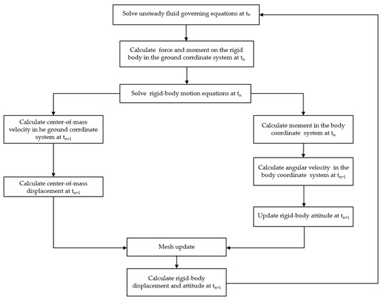
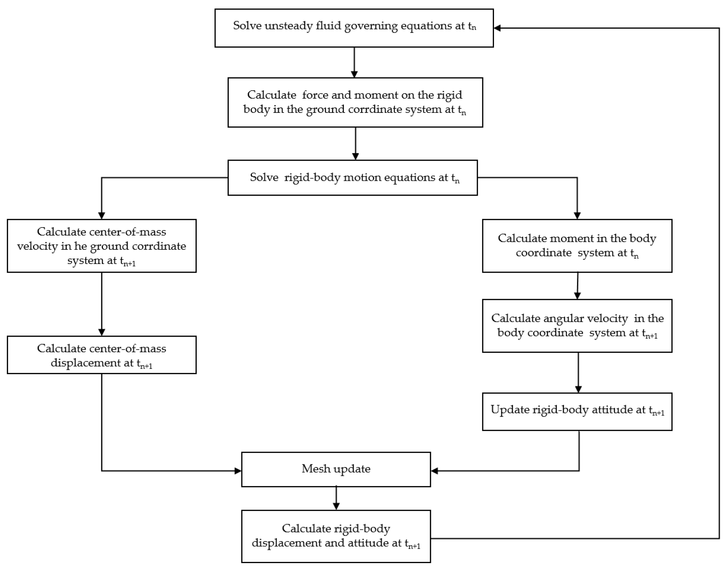
Combining the rigid-body centroid motion equations, rigid-body rotational dynamic equations and attitude solution equations, a coupled solution method integrating CFD and flight dynamics is established for the separation process of cluster munitions, and its calculation procedure is described as follows:
(1) At time step n, solve the fluid governing equations to obtain the aerodynamic loads on the rigid-body surface. Integrate these loads to calculate the resultant force and resultant moment of the rigid body in the ground coordinate system, and convert the moment to the submunition body coordinate system via coordinate transformation relations.
(2) At time step n, the aerodynamic force obtained from the flow-field solution is used to calculate the acceleration of the rigid body in the ground coordinate system according to Equation (11). The centroid velocity and displacement at time step n + 1 are then obtained by integrating the rigid-body motion equations over the time interval . After the position and attitude of the rigid body are updated to n + 1, the mesh and flow field are updated accordingly for the next time step.
(3) Integrate the rotational equations in the submunition body coordinate system based on Equation (12) to obtain the angular velocity of the rigid body at time step n + 1.
(4) Adopt the Euler angles and angular velocity at time step n to solve the Euler angle rates, then conduct time integration to get the rigid-body attitude angles at step n + 1.
(5) Compute the coordinate positions of all nodes on the rigid-body surface at the new time step using the updated centroid velocity, displacement and attitude angles, thus completing the pose update of the rigid body.
(6) Update the mesh by means of dynamic mesh technology, then proceed to the next time step for successive flow field computation.
The above procedures are executed iteratively at each time step to realize real-time two-way coupling among flow field evolution, aerodynamic force variation and motion response of the submunition. The flowchart of the coupled solution is presented as follows (Figure 1).
Figure 1.
Flowchart of the coupled solution procedure.
2.6. Method Validation
To verify the reliability of the numerical method proposed in this paper, numerical simulations are carried out for the three-dimensional external store separation process, and the numerical results are compared with experimental data. Reasonable simplifications are applied to the physical model in simulations: only aerodynamic interference between the wing and external store is considered, while the influence of the fuselage and other external stores is neglected. The wing ejection force, action position, geometric parameters and experimental data are taken from Reference [20], and the detailed parameters are listed in Table 1.
Table 1.
Calculation parameters.
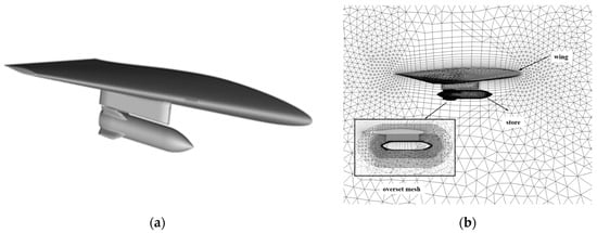
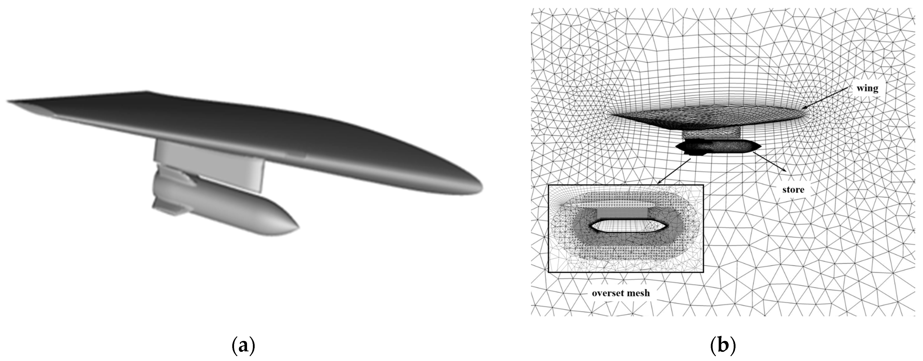
The free-stream Mach number of the test case is 1.2, the angle of attack , static pressure P = 20,646 Pa, static temperature T = 216.65 K, and the simulation time step . The computational model and mesh used for the validation case are shown in Figure 2. An unstructured overset mesh was employed, consisting of a background mesh for the external flow field and an overset mesh surrounding the separating store.
Figure 2.
Geometry and Mesh of the Validation Model: (a) Geometric configuration; (b) Mesh structure.
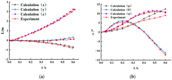
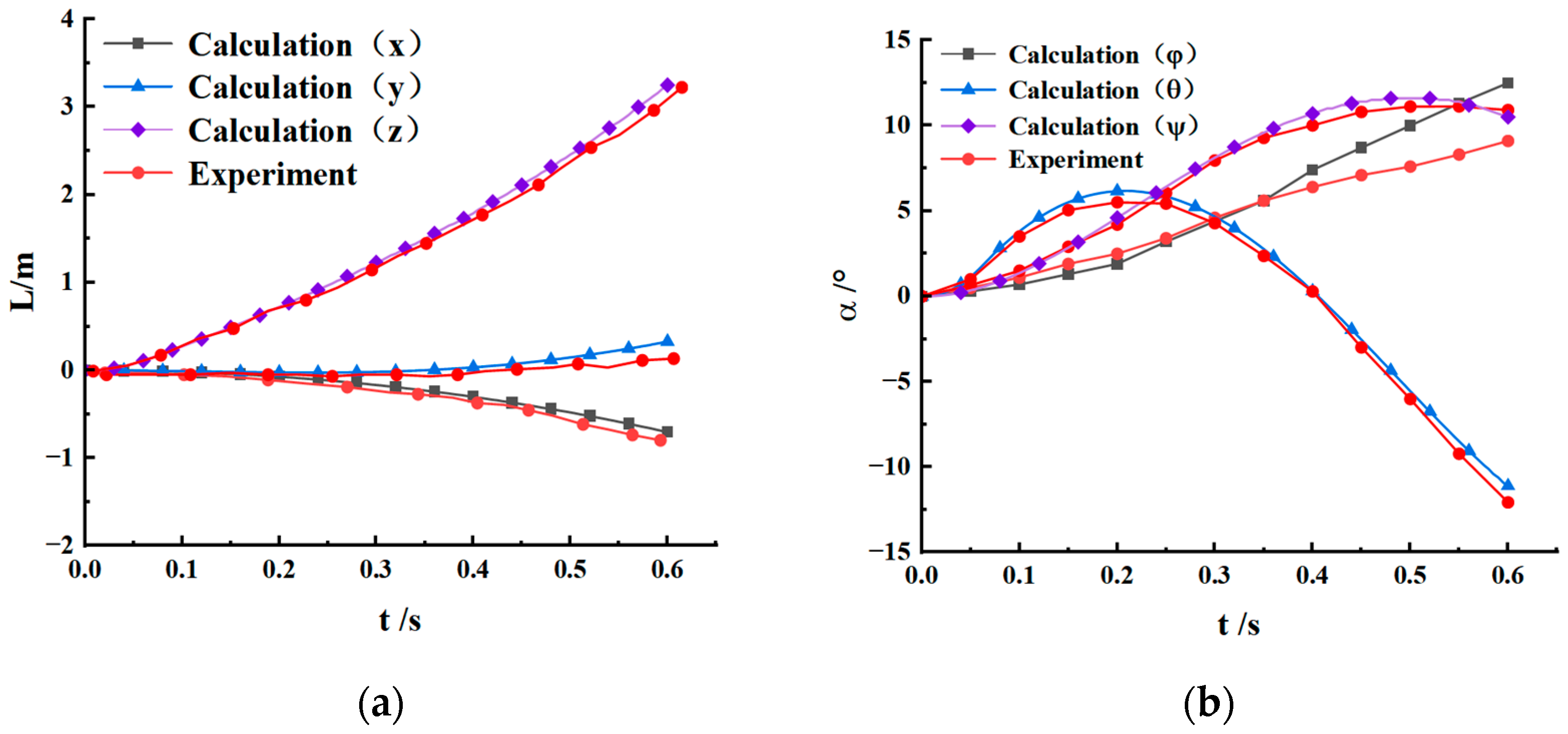
Figure 3 present the time histories of the center-of-mass displacement and Euler angles of the external store, respectively. Comparison of the numerical and experimental results shows good agreement during the initial stage of separation. As the separation progresses, however, the discrepancy between the predicted and measured roll angles gradually increases. This deviation may be attributed to the relatively small axial moment of inertia of the external store, which results in a larger roll response and amplifies the accumulated error in the roll angle. In subsequent simulations, the prediction accuracy of the roll angle can be improved by refining the circumferential mesh around the store and reducing the computational time step. Overall, the numerical results reasonably reproduce the primary center-of-mass motion and attitude evolution of the external store during separation, demonstrating the capability of the coupled CFD–overset-mesh–6DOF method to predict the translational and rotational responses of a separating rigid body. Although the validation case differs from the present configuration in geometry and freestream conditions, both involve unsteady aerodynamic interference and strongly coupled rigid-body motion, and the benchmark therefore provides validation of the numerical framework adopted in this study.
Figure 3.
Numerical and experimental results of the separation displacements and Euler angles of the store: (a) Displacements; (b) Euler angles.
3. Numerical Calculation Model
3.1. Physical Model
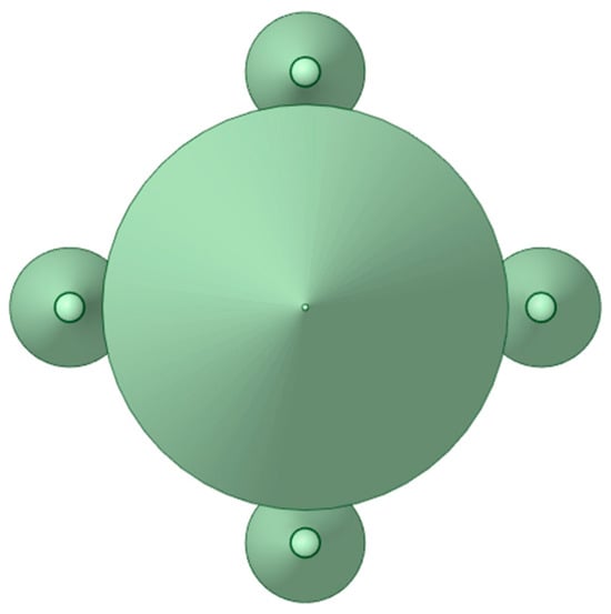
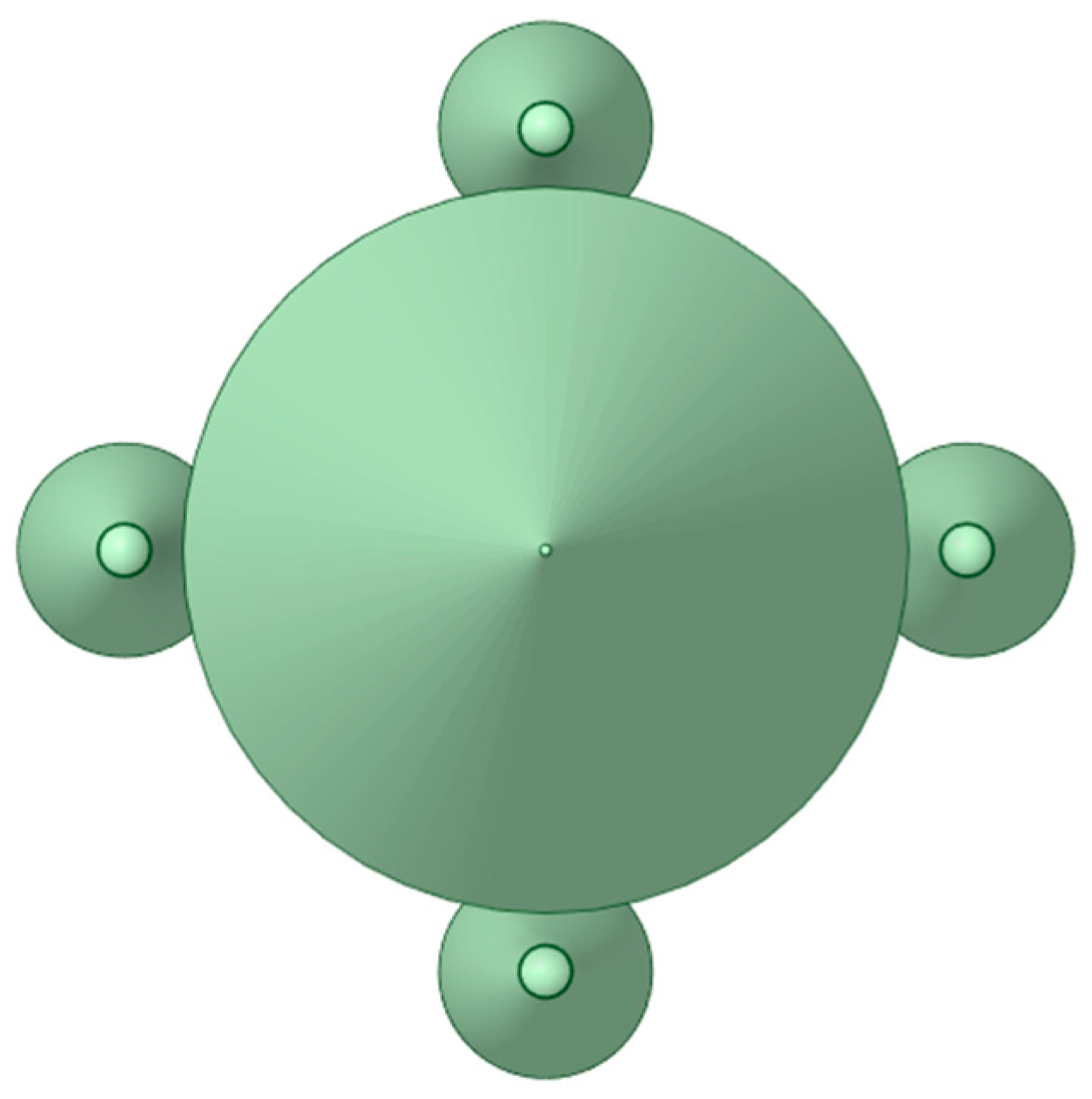
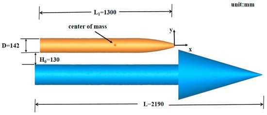
Figure 4 shows the geometric configuration of the cluster munition, in which multiple submunitions are circumferentially arranged inside the carrier. Among these submunitions, the separation direction of the uppermost submunition is opposite to the direction of gravity. Gravity therefore reduces its radial separation capability and increases the potential risk of collision with the carrier. Accordingly, the uppermost submunition is selected as the representative object in the present study. To reduce the computational cost, only the uppermost submunition and the carrier are retained in the numerical model.
Figure 4.
Model of the cluster munition.
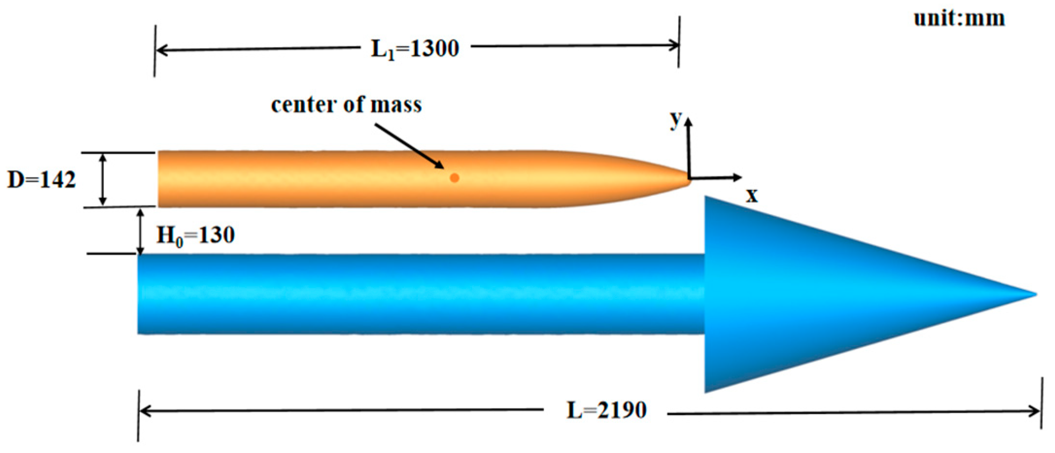
The present numerical study starts from the prescribed initial configuration shown in Figure 5. At the initial instant of the calculation, a clearance of h0 = 130 mm exists between the submunition and the carrier. The preceding deployment and contact-ejection stages are outside the scope of the present study and are therefore not modeled. The present work focuses on the subsequent aerodynamic interference and rigid-body motion of the submunition. The submunition has a diameter of D = 142 mm, L1 = 1300 mm, and a mass of m = 23 kg. The moments of inertia about the three body-fixed axes are , .
Figure 5.
Schematic diagram of the multi-body model.
3.2. Mesh Generation
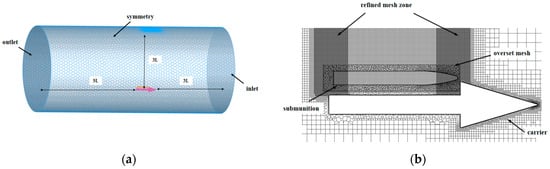
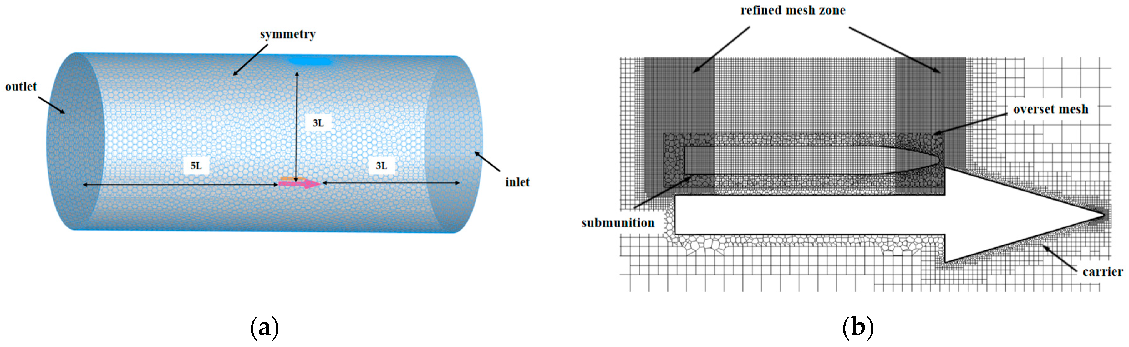
The computational domain and mesh configuration are shown in Figure 6. The inlet boundary is located 3 L upstream of the carrier nose, the outlet boundary is positioned 5 L downstream of the carrier tail, and the outer radial boundary is placed 3 L away from the carrier, where L denotes the carrier length. The computational domain is discretized using an unstructured overset mesh. A stationary background mesh is employed for the carrier and the surrounding flow-field region, while a moving overset mesh is generated around the submunition. The overset mesh moves synchronously with the submunition and exchanges flow-field information with the background mesh through the overlapping region. A sufficiently wide overlap is maintained between the background and overset meshes to ensure the continuous updating of grid connectivity throughout the submunition motion.
Figure 6.
Schematic of computational mesh: (a) Mesh discretization of the flow domain; (b) Local mesh on the X-Y cross-section of the computational domain.
To improve the numerical resolution in critical flow regions, local mesh refinement is applied near the submunition nose, the inner wall of the carrier bay, and the expected trajectory of the submunition. The first-layer height is set to 0.05 mm, with 10 boundary-layer layers and the near-wall mesh resolution selected to ensure y+ < 5, thereby providing adequate resolution of the boundary layer. The mesh size gradually increases from the near-wall regions toward the far field, ensuring a smooth transition while maintaining numerical accuracy and controlling the overall computational cost. The final mesh contains approximately 2.96 million cells, as illustrated in the figure.
3.3. Boundary Conditions
A pressure far-field boundary condition was imposed at the outer boundary of the computational domain, with the freestream Mach number, static pressure, and static temperature specified according to the corresponding flight condition. The freestream parameters prescribed at the far-field boundary are expressed as: , , , where , , and denote the freestream Mach number, static pressure, and static temperature, respectively. The surface of the carrier vehicle was treated as a stationary wall, whereas the submunition surface was defined as a moving wall. At the solid surface, the no-penetration boundary condition is imposed as: . During the calculation, the motion velocities of the stationary carrier wall and the moving submunition wall at each time step are updated through the aerodynamic coupling solution procedure.
Before conducting the unsteady simulation of submunition separation, a steady-state flow field was first obtained with the submunition located inside the bay of the carrier vehicle. The converged steady-state solution was then used as the initial flow field for the subsequent unsteady separation simulation, thereby ensuring the numerical stability and physical reasonableness of the flow field during the initial stage of separation. The time step for the unsteady calculation was set to , and the total physical simulation time was 0.1 s. The residual convergence criterion was set to 10−3 at each physical time step.
To investigate the effects of different initial separation conditions on the aerodynamic characteristics, separation trajectory, and attitude motion of the submunition, the freestream Mach number, initial angle of attack, axial separation velocity, radial separation velocity, lateral separation velocity, and flight altitude were selected as the influencing factors. The ranges of these factors are listed in Table 2.
Table 2.
Numerical calculation conditions.
A single-factor analysis was conducted, in which only one influencing parameter was varied at a time while all other parameters were held constant. The baseline condition was defined as follows: flight altitude H = 20 km, free stream Mach number Ma = 2.0, initial angle of attack of the submunition , and initial axial, radial, and lateral separation velocities of Vx = 0 m/s, Vy = 15 m/s and Vz = 0 m/s, respectively. The physical simulation time for each case was set to 100 ms.
3.4. Grid-Independence Study
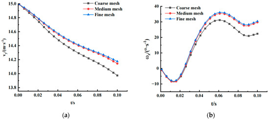
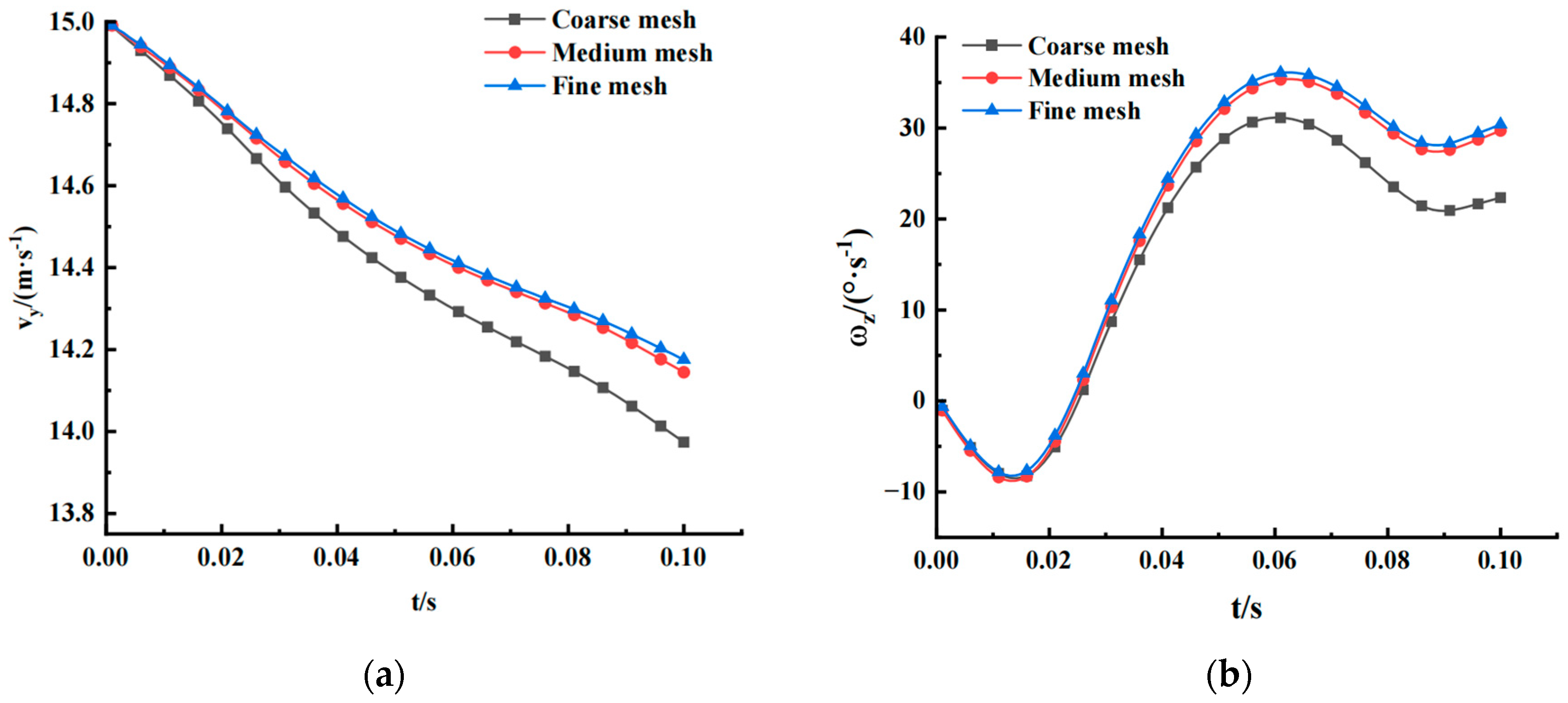
To verify the influence of mesh resolution on the numerical results, three sets of overset meshes with different densities, namely coarse, medium, and fine meshes, were generated, containing approximately 1.85 million, 2.96 million, and 4.33 million cells, respectively. The unsteady separation process under the baseline condition was simulated using the three mesh resolutions. The calculated center-of-mass radial velocity Vy(t) and pitching angular velocity , representing the translational separation response and attitude response of the submunition, respectively, were selected as the evaluation quantities for the grid-independence study, as shown in Figure 7.
Figure 7.
Velocity and angular velocity of the submunition under three mesh densities: (a) Radial velocity; (b) Pitching angular velocity.
As shown in Figure 7, the calculated Vy(t) and histories obtained with the three meshes exhibit generally consistent trends. Some deviations are observed between the coarse-mesh results and those obtained with the medium and fine meshes, and the differences gradually become apparent as the separation proceeds. The results obtained with the medium and fine meshes are in good agreement, with relative differences of 0.2% and 2.3% in the radial velocity Vy and pitching angular velocity at t = 0.1 s, respectively, indicating that further mesh refinement has only a minor influence on the separation motion and attitude response considered in this study. Considering both numerical accuracy and computational cost, the medium mesh containing approximately 2.96 million cells was adopted for the subsequent numerical simulations.
4. Results and Discussion
Based on the baseline condition and single-factor simulation cases defined in Section 3.3, this chapter analyzes the unsteady aerodynamic interference and separation attitude during the multi-body separation process. First, the flow-field structures and attitude evolution of the submunition under the baseline condition are investigated. The effects of different initial separation parameters on the aerodynamic and dynamic characteristics of the submunition are then discussed.
4.1. Flow-Field Evolution and Attitude Variation Under the Baseline Condition
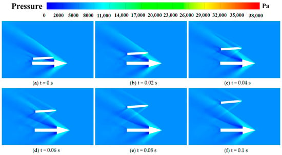
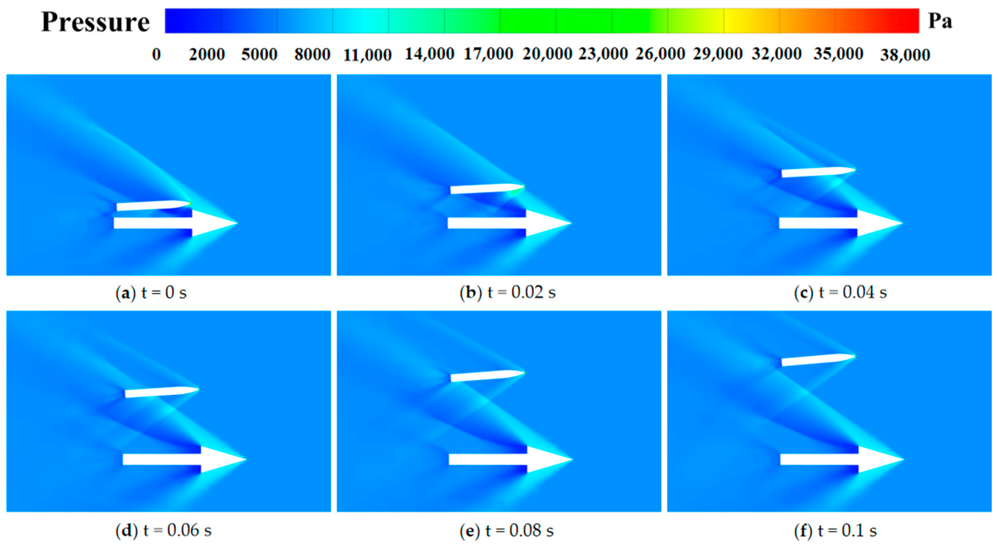
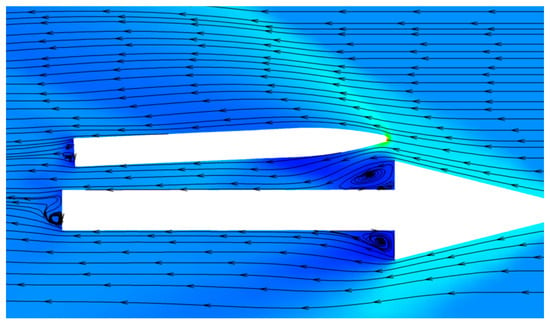
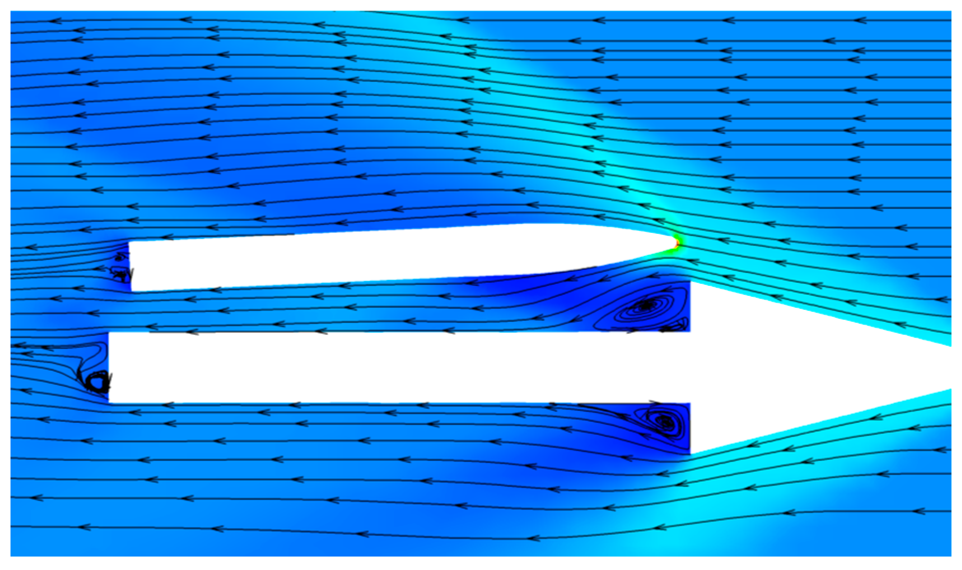
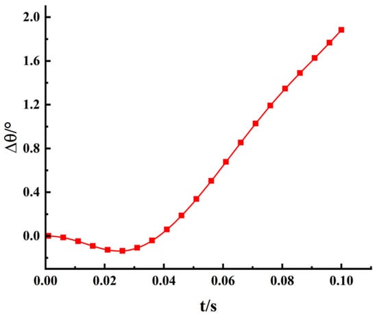
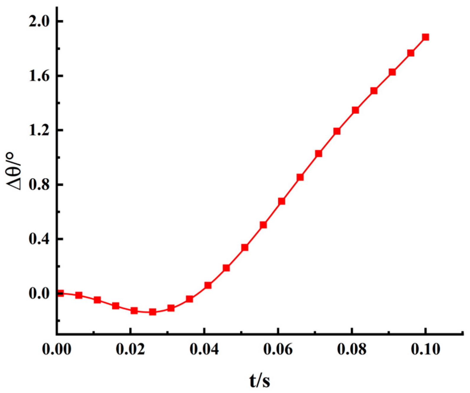
To analyze the submunition surface pressure distribution and attitude variation during the multi-body separation process, the baseline condition defined in Section 3.3 is selected for numerical simulation. Figure 8 presents the pressure distributions at different separation times, Figure 9 shows the streamline distribution at the initial separation instant, and Figure 10 presents the time history of the submunition pitch-angle variation. Since the attitude variation in the submunition under the baseline condition is dominated by pitching motion in the longitudinal plane, the pitch-angle variation is used to characterize the attitude response in this section.
Figure 8.
Pressure distributions at different separation times under the baseline condition: (a) T = 0 s; (b) T = 0.02 s; (c) T = 0.04 s; (d) T = 0.06 s; (e) T = 0.08 s; (f) T = 0.10 s.
Figure 9.
Streamline distribution at the initial separation instant.
Figure 10.
Time history of the submunition pitch-angle variation under the baseline condition.
As shown in Figure 8 and Figure 9, at the initial stage of separation, the carrier bow shock impinges on the upper surface of the submunition nose, forming a localized high-pressure region. The shock generated ahead of the submunition interacts with the carrier and is reflected from its surface, intensifying the shock-wave interference between the two bodies. Meanwhile, the abrupt geometric change at the carrier shoulder induces flow expansion and separation, forming a local recirculation region characterized by relatively low pressure. The recirculation region remains at a certain distance from the submunition surface; therefore, its influence is primarily manifested through changes in the local flow field and pressure distribution near the lower surface of the submunition. The combined effects of the shock-wave interference and shoulder-induced separated flow produce an asymmetric pressure distribution over the submunition, resulting in a nose-down aerodynamic pitching moment during the initial separation stage. Driven by the initial radial separation velocity, the submunition gradually moves away from the carrier. During the period of 0.02–0.04 s, the region affected by the carrier shock on the submunition surface shifts from the nose toward the mid-body, and the submunition nose gradually moves out of the primary influence region of the carrier shock. Meanwhile, the impingement location of the reflected shock induced by the submunition shock moves toward the submunition tail. As the relative position between the submunition and the carrier changes, the pressure on the lower surface of the submunition increases and gradually exceeds that on the upper surface, generating a nose-up pitching moment along the positive Z-axis. The pitching angular velocity therefore changes from negative to positive and continues to increase. This change is consistent with the attitude response shown in Figure 10: the pitch angle decreases during the initial stage and reaches its minimum value at approximately 0.03 s, after which it begins to increase, indicating a gradual transition of the submunition from nose-down to nose-up motion. During the period of 0.06–0.1 s, the distance between the submunition and the carrier further increases, and the influence of the carrier bow shock on the submunition weakens. The submunition moves largely out of the main aerodynamic interference region of the carrier, while a relatively complete detached shock gradually forms ahead of the submunition nose. The pressure distribution over the submunition surface becomes more uniform, and the pitching moment and the rate of attitude-angle variation consequently decrease.
4.2. Effect of Mach Number on Separation Characteristics
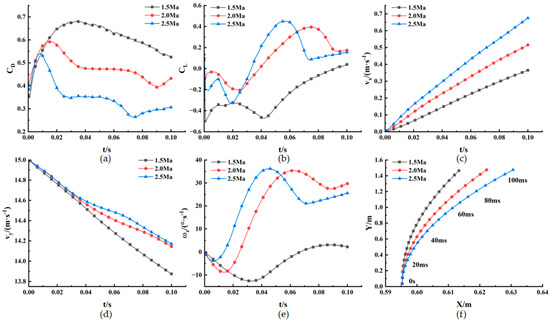
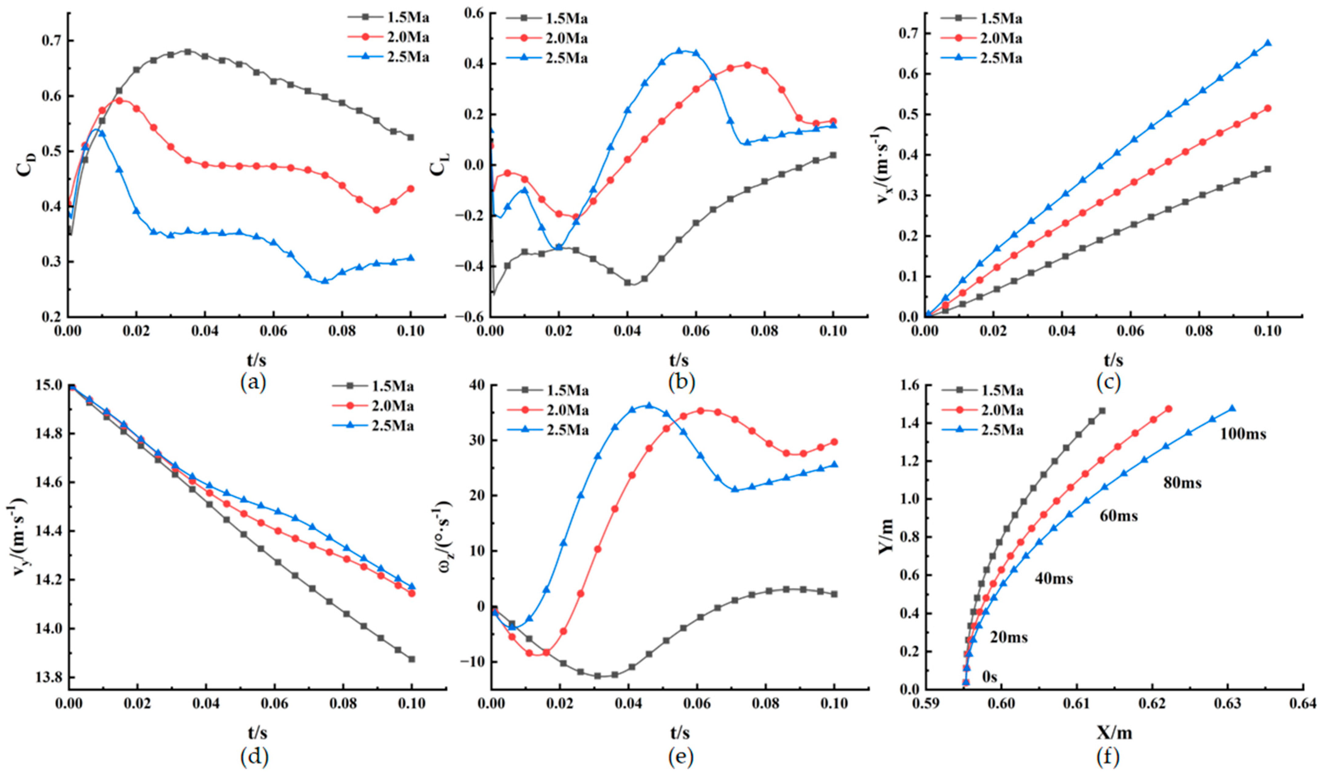
Figure 11 presents the time histories of separation parameters of the submunition at freestream Mach numbers of Ma = 1.5, 2.0, 2.5, a flight altitude of H = 20 km, an initial angle of attack of 3° and initial separation velocities of Vx0 = 0 m/s, Vy0 = 15 m/s, Vz0 = 0 m/s.
Figure 11.
Time histories of separation parameters of the submunition at different freestream Mach numbers: (a) drag coefficient; (b) lift coefficient; (c) relative velocity in the X-direction; (d) relative velocity in the Y-direction; (e) pitching angular velocity; (f) relative displacement of the center of mass.
As the freestream Mach number increases from 1.5 to 2.5, the carrier bow shock becomes stronger and its shock angle decreases. As shown in Figure 11, under the same initial separation velocity, the submunition passes through the main shock-interference region of the carrier earlier. Accordingly, the drag coefficient decreases overall, while the lift coefficient changes from negative to positive earlier and its positive peak increases. Under the action of the axial aerodynamic force, the relative velocity of the submunition in the X-direction gradually increases. For all cases, the relative velocity in the Y-direction decreases with time. At higher Mach numbers, the lift coefficient becomes positive earlier, thereby reducing the decay rate of the Y-direction relative velocity. Under high-Mach-number conditions, the pressure difference between the upper and lower surfaces of the submunition increases, resulting in a larger pitching angular velocity and a more pronounced attitude variation. Because the X-direction relative velocity increases more rapidly and the Y-direction relative velocity decreases more slowly, the separation distance between the submunition and the carrier increases with Mach number over the same period, allowing the submunition to leave the main aerodynamic interference region of the carrier earlier.
4.3. Effect of Initial Submunition Angle of Attack on Separation Characteristics
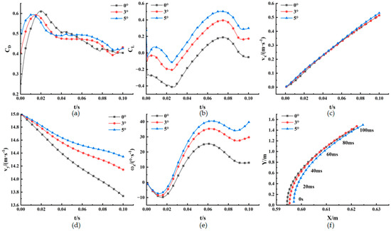
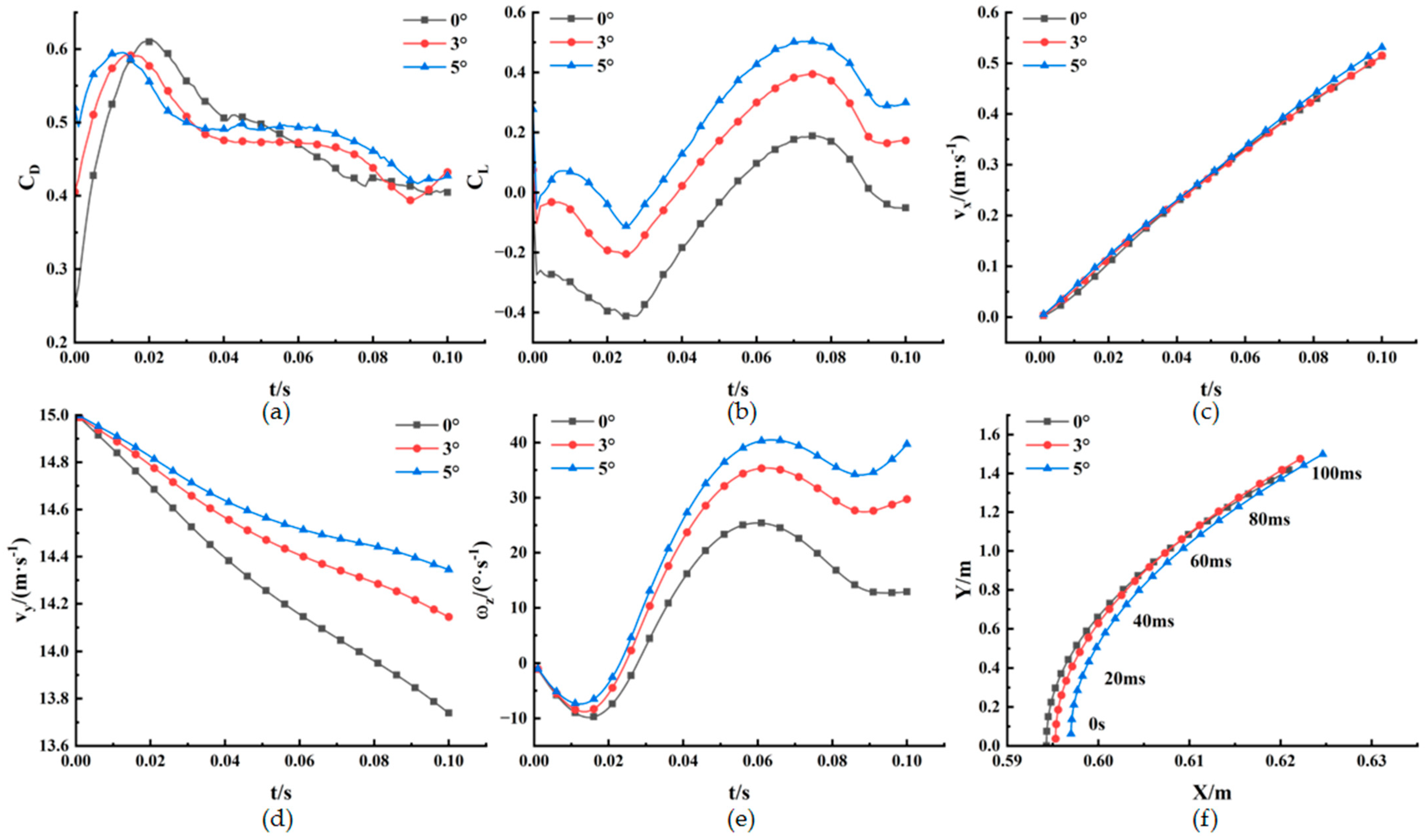
Figure 12 presents the time histories of separation parameters of the submunition at a freestream Mach number of Ma = 2.0, a flight altitude of H = 20 km, initial angles of attack of 0°, 3° and 5°, and initial separation velocities of Vx0 = 0 m/s, Vy0 = 15 m/s, Vz0 = 0 m/s.
Figure 12.
Time histories of separation parameters of the submunition at different angles of attack: (a) drag coefficient; (b) lift coefficient; (c) relative velocity in the X-direction; (d) relative velocity in the Y-direction; (e) pitching angular velocity; (f) relative displacement of the center of mass.
As shown in Figure 12, increasing the initial angle of attack changes the location at which the carrier shock acts on the submunition surface and advances the occurrence of the drag-coefficient peak. At an initial angle of attack of 0°, the carrier shock first acts on the upper surface of the submunition nose, producing negative lift and a nose-down pitching moment. As the initial angle of attack increases, the shock-affected region gradually shifts toward the lower surface of the submunition, increasing the lower-surface pressure and weakening the nose-down pitching moment. Consequently, the lift coefficient and pitching angular velocity change from negative to positive earlier, and their positive peaks increase. The differences in the X-direction relative velocity among the cases with different initial angles of attack are relatively small, indicating that the initial angle of attack has a limited influence on the axial motion. A larger initial angle of attack increases the normal aerodynamic force, reduces the decay of the Y-direction relative velocity, and consequently increases the radial separation distance and the relative displacement of the submunition center of mass.
4.4. Effects of Initial Separation Velocity on Separation Characteristics
4.4.1. Effect of Initial Axial Separation Velocity on Separation Characteristics
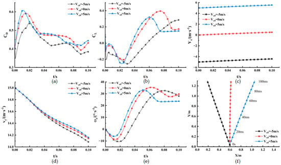
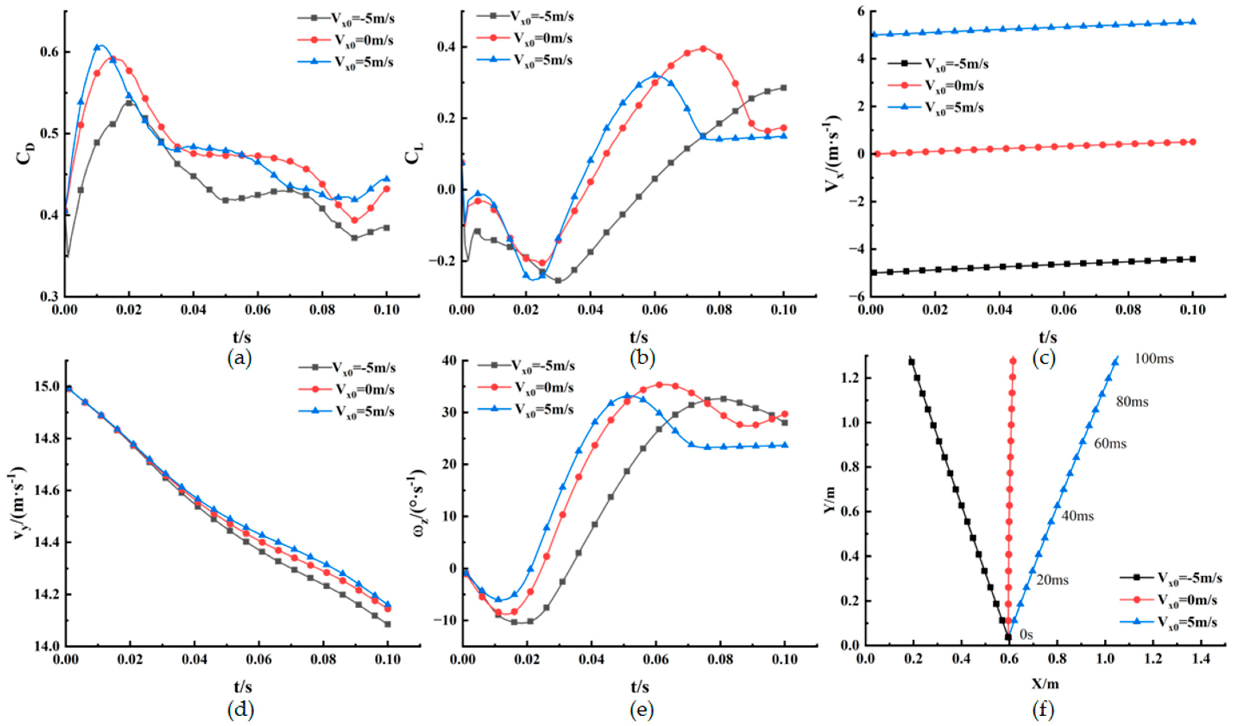
Figure 13 presents the time histories of separation parameters of the submunition at a freestream Mach number of Ma = 2.0, a flight altitude of H = 20 km, an initial angle of attack of 3°, axial initial ejection velocities of Vx0 = −5 m/s, 0 m/s, 5 m/s, and Vy0 = 15 m/s, Vz0 = 0 m/s.
Figure 13.
Time histories of separation parameters of the submunition at different initial axial separation velocities: (a) drag coefficient; (b) lift coefficient; (c) relative velocity in the X-direction; (d) relative velocity in the Y-direction; (e) pitching angular velocity; (f) relative displacement of the center of mass.
As shown in Figure 13, the relative velocity of the submunition in the X-direction gradually increases under all conditions. This indicates that the initial axial separation velocity Vx0 changes the motion of the submunition relative to the carrier bow shock, expansion-wave region, and wake-interference region, thereby affecting the aerodynamic loads acting on the submunition. When Vx0 = 5 m/s the submunition moves forward relative to the carrier and enters the region of strong interference from the carrier bow shock earlier. Consequently, the surface pressure changes rapidly, the peak drag coefficient increases, and the lift coefficient and pitching angular velocity change from negative to positive earlier. When Vx0 = −5 m/s, the submunition moves rearward relative to the carrier and is more strongly affected by the low-pressure regions associated with the wake and expansion waves. As a result, the peak drag coefficient is lower and occurs later, while the lift coefficient and pitching angular velocity remain negative for a longer period. As Vx0 increases, the time required for the submunition to pass through the near-field interference region of the carrier decreases, thereby shortening the duration of the complex wave-system effects on the submunition and reducing the decrease in the Y-direction relative velocity. As shown in Figure 13f, the radial trajectories of the submunition under the three conditions are similar, whereas the axial displacements differ considerably.
4.4.2. Effect of Initial Radial Separation Velocity on Separation Characteristics
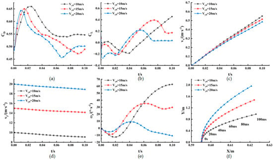
Figure 14 presents the time histories of separation parameters of the submunition at a freestream Mach number of Ma = 2.0, a flight altitude of H = 20 km, an initial angle of attack of 3°, Vx0 = 0 m/s, radial initial ejection velocities of Vy0 = 10 m/s, 15 m/s, 20 m/s, and Vz0 = 0 m/s.
Figure 14.
Time histories of separation parameters of the submunition at different initial radial separation velocities: (a) drag coefficient; (b) lift coefficient; (c) relative velocity in the X-direction; (d) relative velocity in the Y-direction; (e) pitching angular velocity; (f) relative displacement of the center of mass.
The initial radial separation velocity affects the interaction between the carrier and the submunition by changing the radial distance between the two bodies. During the initial stage of separation, the submunition is subjected to the carrier shock, causing the drag coefficient to increase rapidly, while the lift coefficient and pitching moment are negative. As shown in Figure 14, as Vy0 increases from 10 m/s to 20 m/s, the submunition moves away from the main aerodynamic interference region of the carrier more rapidly. Consequently, the drag-coefficient peak occurs earlier, and the lift coefficient changes from negative to positive at an earlier time. A larger Vy0 shortens the duration of the effects of the carrier shock, reflected shock, and expansion waves on the submunition surface, thereby reducing the overall pitching angular velocity and slowing the attitude variation. Under all conditions, the relative velocity of the submunition in the X-direction gradually increases. At Vy0 = 10 m/s, the submunition remains within the carrier shock-interference region for a relatively longer period, resulting in a more pronounced cumulative effect of the axial aerodynamic force and, consequently, a larger increase in Vx. The relative velocity Vy gradually decreases with time under all conditions, whereas a larger initial radial separation velocity corresponds to a smaller reduction in Vy. As shown in Figure 14f, the differences in axial displacement among the three conditions are relatively small, while the radial displacement increases markedly with Vy0.
4.4.3. Effect of Initial Lateral Separation Velocity on Separation Characteristics
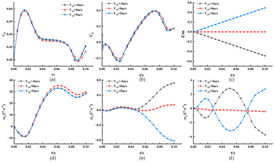
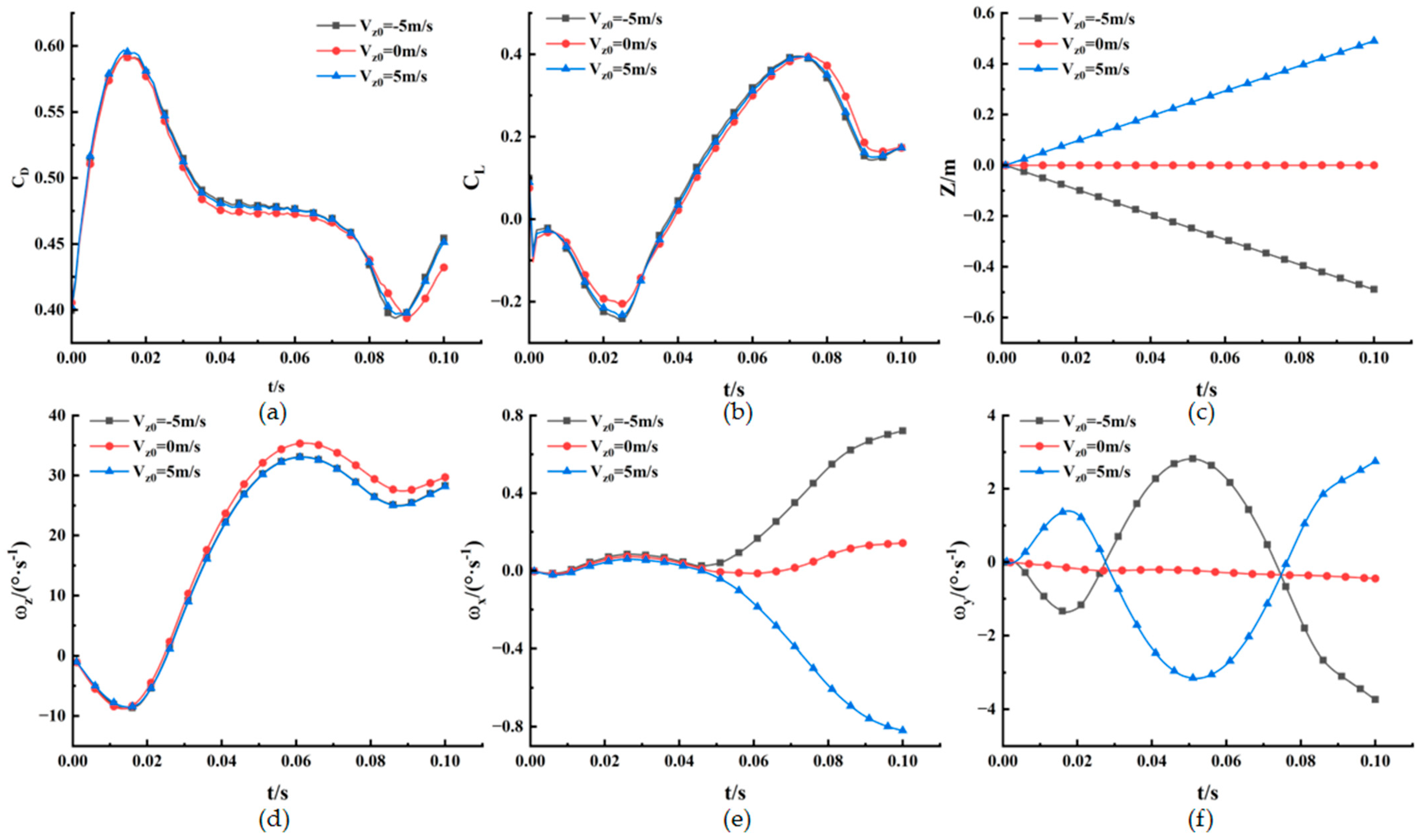
Figure 15 presents the time histories of separation parameters of the submunition at a freestream Mach number of Ma = 2.0, a flight altitude of H = 20 km, an initial angle of attack of 3°, Vx0= 0 m/s, Vy0 = 15 m/s, and lateral initial ejection velocities of Vz0 = −5 m/s, 0 m/s, 5 m/s.
Figure 15.
Time histories of separation parameters of the submunition at different initial lateral separation velocities: (a) drag coefficient; (b) lift coefficient; (c) relative displacement in the Z-direction; (d) pitching angular velocity; (e) rolling angular velocity; (f) yawing angular velocity.
As shown in Figure 15a,b,d, the drag coefficient, lift coefficient, and pitching angular velocity exhibit generally similar trends under different Vz0 conditions, indicating that the initial lateral separation velocity has only a limited influence on the pressure distribution over the upper and lower surfaces of the submunition and on the longitudinal aerodynamic forces. Figure 15c shows that when Vz0 = 0 m/s, the lateral relative displacement of the submunition remains close to zero. When , the lateral displacement increases approximately linearly with time, while the two cases exhibit opposite motion directions and similar displacement magnitudes. This indicates that the lateral motion of the submunition is primarily determined by the initial lateral separation velocity. The lateral velocity induces sideslip motion, disrupts the symmetry of the flow field around the submunition, and alters the axial aerodynamic force. As shown in Figure 15e,f, the initial lateral separation velocity has a pronounced influence on the rolling and yawing motions. When Vz0 is close to zero, the pressure distributions on the two sides of the submunition are relatively symmetric, resulting in small rolling and yawing moments and correspondingly low angular velocities. As increases, the sideslip motion and the pressure difference between the two sides of the submunition increase, leading to larger rolling and yawing angular velocities. Since the sign of Vz0 primarily changes the direction of lateral motion and the corresponding aerodynamic moments, the magnitudes of the rolling and yawing angular velocities are approximately symmetric about Vz0 = 0.
The rolling and yawing angular velocities continue to increase during the separation process, indicating that Vz0 has a persistent influence on the attitude motion. As increases, the initial lateral disturbance and the resulting aerodynamic moments become stronger, causing the pitching and yawing angular velocities to accumulate further during the subsequent motion. Therefore, an excessively large lateral separation velocity is unfavorable for separation-attitude stability and may increase the difficulty of subsequent attitude control. To maintain a stable and controllable motion state after separation, the lateral separation velocity should be tightly constrained.
4.5. Effect of Flight Altitude on Separation Characteristics
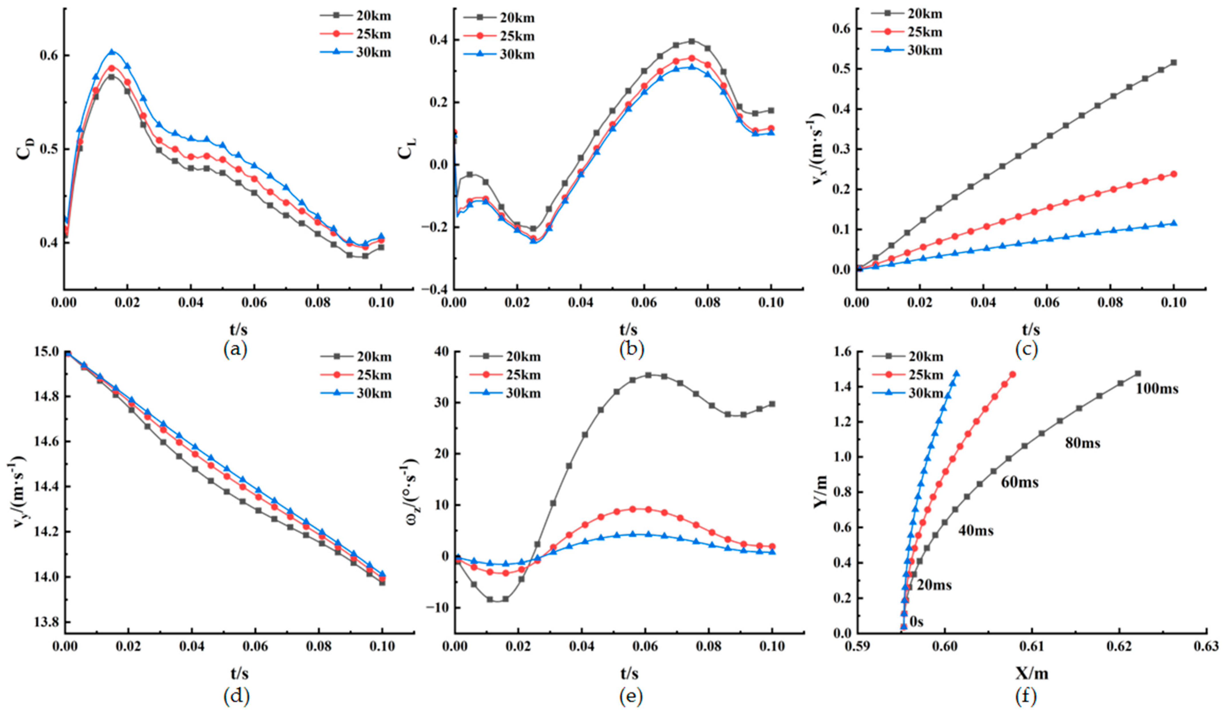
Figure 16 presents the time histories of separation parameters of the submunition at a freestream Mach number of Ma = 2.0, flight altitudes of H = 20, 25, 30 km, an initial angle of attack of 3°, Vx0 = 0 m/s, Vy0 = 15 m/s, and initial separation velocities of Vx0 = 0 m/s, Vy0 = 15 m/s, Vz0 = 0 m/s.
Figure 16.
Time histories of separation parameters of the submunition at different flight altitudes: (a) drag coefficient; (b) lift coefficient; (c) relative velocity in the X-direction; (d) relative velocity in the Y-direction; (e) pitching angular velocity; (f) relative displacement of the center of mass.
As shown in Figure 16, as the separation altitude increases, the freestream density decreases, leading to a reduction in the Reynolds number and a slight increase in the drag coefficient of the submunition. At an altitude of 20 km, the carrier shock interference is stronger, and the pressure difference between the upper and lower surfaces of the submunition varies more significantly, resulting in larger fluctuations in the lift coefficient and pitching angular velocity. The stronger negative normal aerodynamic force suppresses the separation motion in the Y-direction, producing a larger reduction in Vy. As the altitude increases, the aerodynamic forces and moments acting on the submunition surface decrease, and the variations in the lift coefficient, pitching angular velocity, and Y-direction relative velocity are correspondingly reduced. Meanwhile, the freestream dynamic pressure decreases significantly with altitude, weakening the axial aerodynamic force acting on the submunition. Consequently, the acceleration in the X-direction decreases, and the growth rate of Vx gradually declines. Owing to the reduced aerodynamic loading, the relative displacement of the submunition center of mass within the same simulated period decreases with increasing altitude.
5. Conclusions
Based on numerical simulations combined with the three-dimensional overset mesh technique, this paper investigates the unsteady aerodynamic interference and multi-degree-of-freedom motion characteristics of submunition during the multi-body separation of carrier-submunition system under supersonic flight conditions in near space. The effects of free-stream Mach number, submunition initial separation attitude angle, initial separation velocities (axial velocity, radial velocity and lateral velocity), as well as flight altitude on separation attitudes are systematically analyzed. The main conclusions are summarized as follows:
(1) Although the freestream density in near space is relatively low, the shock-wave structure and the variation in its impingement location on the submunition surface remain important factors governing the motion of the submunition during the initial separation stage. An increase in the freestream Mach number strengthens the carrier shock wave, intensifies the aerodynamic interference acting on the submunition, and results in a more pronounced attitude response. Increasing the initial angle of attack changes the impingement location of the carrier shock wave on the submunition surface, which promotes radial separation but also enhances the nose-up motion.
(2) The initial axial, radial, and lateral separation velocities have distinctly different effects on the motion characteristics. The initial axial separation velocity mainly changes the process by which the submunition passes through the carrier shock-wave, expansion-wave, and wake-interference regions. The initial radial separation velocity determines the growth rate of the radial distance between the two bodies and affects the duration of the carrier shock-wave interference. The initial lateral separation velocity significantly enhances the rolling and yawing motions. Under the low-dynamic-pressure conditions of near space, the aerodynamic forces have a relatively limited effect on modifying the velocity of the submunition; therefore, its motion during the initial separation stage is strongly influenced by the initial separation velocity.
(3) As the flight altitude increases, the air density decreases, resulting in reductions in the aerodynamic forces and moments acting on the submunition. Consequently, the variations in velocity, displacement, and attitude are all reduced.
(4) Compared with separation under conventional low-altitude conditions, the low dynamic pressure in near space weakens the cumulative effects of aerodynamic loading but does not eliminate the transient aerodynamic interference induced by the complex wave system. Considering the combined effects of the initial separation conditions, increasing the initial radial separation velocity, maintaining Vz0 close to zero, and appropriately selecting the initial angle of attack and freestream Mach number are beneficial for reducing attitude disturbances, increasing the separation clearance, and improving the stability and reliability of carrier–submunition separation in near space.
Author Contributions
Conceptualization, S.S. and L.T.; Methodology, R.T. and L.T.; Validation, R.T.; Formal analysis, S.S.; Supervision, H.W., R.T. and L.T.; Funding acquisition, H.W.; Writing—original draft, S.S.; Writing—review and editing, S.S., L.T.; Visualization, S.S. All authors have read and agreed to the published version of the manuscript.
Funding
This research received no external funding.
Data Availability Statement
The datasets used in this study are available from the corresponding author upon reasonable request.
Conflicts of Interest
The authors declare no conflicts of interest.
References
- Stephens, H. Near-space. Air Force Mag. 2005, 88, 36–40. [Google Scholar]
- Hayward, D.M.; Duff, A.; Wagner, C. F-35 weapons design integration. In Proceedings of the 2018 Aviation Technology, Integration, and Operations Conference, Atlanta, GA, USA, 25–29 June 2018. [Google Scholar]
- Moelyadi, M.A.; Breitsamter, C.; Laschka, B. Stage-separation aerodynamics of two-stage space transport systems. Part 1: Steady-state simulations. J. Spacecr. Rockets 2008, 45, 1230–1239. [Google Scholar] [CrossRef] [Scilit]
- Moelyadi, M.A.; Breitsamter, C.; Laschka, B. Stage-separation aerodynamics of two-stage space transport systems. Part 2: Unsteady simulation. J. Spacecr. Rockets 2008, 45, 1240–1250. [Google Scholar] [CrossRef] [Scilit]
- Song, W.; Lu, W.; Jiang, Z. Wind tunnel drop model test of nose cap separation of supersonic vehicle. J. Exp. Fluid. Mech. 2017, 31, 45–50, 70. [Google Scholar]
- Wang, Y.; Wang, Y.; Jiang, Z. Numerical investigation of aerodynamic separation schemes for a two-stage-to-orbit-like two-body system. Aerosp. Sci. Technol. 2022, 131, 107995. [Google Scholar] [CrossRef] [Scilit]
- Cui, P.; Jia, H.; Chen, J.; Zhou, G.; Wu, X.; Ma, M.; Li, H.; Tang, J. Numerical investigation on unsteady shock wave/vortex/turbulent boundary layer interactions of a hypersonic vehicle during its shroud separation. Aerospace 2022, 9, 619. [Google Scholar] [CrossRef] [Scilit]
- Hu, R.; Wu, Z.; Wu, Z.; Wang, X.; Tian, Z. Aerodynamic map for soft and hard hypersonic level flight in near space. Acta Mech. Sin. 2009, 25, 571–575. [Google Scholar] [CrossRef] [Scilit]
- Xu, K.; Li, Q.; Li, Z. Direct modeling-based computational fluid dynamics. Sci. Sin. Phys. Mech. Astron. 2014, 44, 519–530. [Google Scholar] [CrossRef] [Scilit]
- Ye, Y.; Zhang, H.; Jiang, Q.; Zhang, X. Some key problems in the study of aerodynamic characteristics of near-space hypersonic vehicles. Chin. J. Theor. Appl. Mech. 2018, 50, 1292–1310. [Google Scholar]
- Panneerselvam, S.; Soundararajan, P.; Nagarajan, V.; Santhakumar, S. Dispenser-induced aerodynamic interference loads on submunition during dispense. In Proceedings of the 15th Applied Aerodynamics Conference, Atlanta, GA, USA, 23–25 June 1997. [Google Scholar]
- Woods, W.C.; Holland, S.D.; DiFulvio, M. Hyper-X stage separation wind-tunnel test program. J. Spacecr. Rockets 2001, 38, 811–819. [Google Scholar] [CrossRef] [Scilit] [PubMed]
- Holden, M.S.; Harvey, J.K.; MacLean, M.; Walker, B. Development and application of a new ground test capability to conduct full-scale shroud and stage separation studies at duplicated flight conditions. In Proceedings of the 43rd AIAA Aerospace Sciences Meeting and Exhibit, Reno, NV, USA, 10–13 January 2005. [Google Scholar]
- Murray, N.E.; Jansen, B.J.; Gui, L.; Seiner, J.M.; Birkbeck, R. Measurements of store separation dynamics. In Proceedings of the 47th AIAA Aerospace Sciences Meeting Including the New Horizons Forum and Aerospace Exposition, Orlando, FL, USA, 5–8 January 2009. [Google Scholar]
- Jiang, Z.; Song, W.; Jia, Q.; Chen, N. Wind tunnel free-flight test for multi-bodies separation. Acta Aerodyn. Sin. 2016, 34, 581–586. [Google Scholar]
- Chin, D.; Granlund, K.; Maatz, I.; Schmit, R.F.; Reeder, M.F. Stochastic store trajectory of ice models from a cavity into supersonic flow. J. Aircr. 2019, 56, 1313–1319. [Google Scholar] [CrossRef] [Scilit]
- Koomullil, R.P.; Cheng, G.C.; Soni, B.K.; Noack, R.; Prewitt, N.C. Moving-body simulations using an overset framework with rigid-body dynamics. Math. Comput. Simul. 2008, 78, 618–626. [Google Scholar] [CrossRef] [Scilit]
- Zhang, M.; Jiang, Y.; Cheng, L.; Yang, H.; Liu, Q. Numerical analysis of separation of supersonic submunition based on nested grid. Acta Armamentarii 2019, 40, 79–88. [Google Scholar]
- Tian, S.; Fu, J.; Chen, J. A numerical method for multi-body separation with collisions. Aerosp. Sci. Technol. 2021, 109, 106426. [Google Scholar] [CrossRef] [Scilit]
- Panagiotopoulos, E.E.; Kyparissis, S.D. CFD transonic store separation trajectory predictions with comparison to wind tunnel investigations. Int. J. Eng. 2010, 3, 538–553. [Google Scholar]
- Wang, J.; Wang, H.; Jiang, K.; Jiang, S. Analysis of the aerodynamic impact of the dispenser stance for the separation of cluster munitions. Eng. Appl. Comput. Fluid Mech. 2016, 10, 427–440. [Google Scholar] [CrossRef] [Scilit]
- Chu, J.; Li, D. Aerodynamic numerical analysis of the three-stage submunition separation scheme. J. Ordnance Equip. Eng. 2023, 44, 22–28. [Google Scholar] [CrossRef]
- Lei, J.; Niu, J.; Wang, S.; Zhou, Q. Numerical simulation of the effect of initial separation conditions on the safety of an aerial bomb separated from an aircraft. Acta Armamentarii 2016, 37, 357–366. [Google Scholar]
- Cui, Y.; Xu, Y.; Lyu, F.; Zhao, F.; Zhang, Y.; Sun, J.; Zuo, G. Influencing factors of weapon separation of hypersonic vehicles in near space. Acta Aeronaut. Astronaut. Sin. 2023, 44, 128539. [Google Scholar]
- Fatima, K.; Ahmed, S.; Irfan, M.; Khan, H.N.; Masud, J.; Shahzad, A.; Akram, F.B.; Safdar, M.M. The effects of flight and ejection parameters on store separation. In Proceedings of the AIAA SciTech Forum 2026, Orlando, FL, USA, 12–16 January 2026. [Google Scholar]
- ANSYS, Inc. ANSYS Fluent Theory Guide, Release 2023 R1; ANSYS, Inc.: Canonsburg, PA, USA, 2023. [Google Scholar]


Disclaimer/Publisher’s Note: The statements, opinions and data contained in all publications are solely those of the individual author(s) and contributor(s) and not of MDPI and/or the editor(s). MDPI and/or the editor(s) disclaim responsibility for any injury to people or property resulting from any ideas, methods, instructions or products referred to in the content. |
© 2026 by the authors. Licensee MDPI, Basel, Switzerland. This article is an open access article distributed under the terms and conditions of the Creative Commons Attribution (CC BY) license.