


Abstract
Surface icing poses a significant risk to unmanned aerial vehicles (UAVs) and compact aerospace platforms, where limited onboard power and space require efficient anti-/de-icing surfaces. In this study, micro/nanostructures were fabricated on TC4 titanium alloy (Ti–6Al–4V) surfaces by femtosecond laser processing at different scanning speeds. The effects of scanning speed on surface morphology, wettability, static freezing, dynamic droplet behavior, and electrothermal de-icing performance were systematically investigated. Increasing the scanning speed induced nonlinear changes in microstructure height and surface roughness, while variations in ablation intensity caused nonuniform material redistribution. The surface processed at 250 mm/s showed the best anti-icing performance, with a water contact angle of 157.5 ± 0.5° and a maximum freezing delay 21.5 times longer than untreated TC4. During electrothermal de-icing, melting initiated at discrete ice–substrate contact points, forming coalesced meltwater films, while interfacial stress concentration promoted crack propagation and rapid ice detachment. Compared with untreated surfaces, ice detachment time (250 mm/s) achieved complete ice detachment at approximately 152 s, whereas ice on the untreated surface remained adhered after 270 s of continuous heating, representing a de-icing time reduction of at least 44%. These results demonstrate that combining laser-fabricated microstructures with electrothermal heating effectively reduces real ice–substrate contact, providing an enhanced anti-/de-icing strategy for lightweight, long-endurance UAV applications under identical electrical input.
1. Introduction
Surface icing frequently occurs on rotors, wing leading edges, fuselage skins, and sensor windows of unmanned aerial vehicles (UAVs) and other compact aerospace platforms operating in cold, humid, or cloudy environments [1,2]. Ice accumulation can significantly alter the aerodynamic profile of aircraft, increase drag, reduce lift, and introduce additional structural loads. In severe cases, it may impair attitude control, sensor reliability, and flight safety [3,4]. Compared with large manned aircraft, UAVs are more sensitive to icing because of limited onboard power, payload capacity, and installation space for anti-/de-icing devices [5,6,7]. These constraints are particularly critical for long-endurance missions, where ice protection systems must operate repeatedly or continuously with low energy consumption [8,9,10]. Therefore, the development of lightweight, compact, and energy-efficient surface ice protection strategies is essential for improving the operational reliability of UAVs and other power-limited aerospace platforms. In addition, the dynamic response of supercooled droplets to surface wettability and environmental conditions is an important consideration in icing mitigation [11].
In addition to fixed-wing platforms, rotor-based UAVs are particularly susceptible to propeller icing. Rotational motion induces centrifugally driven water runback, non-uniform ice accretion along the blade span, and altered aerodynamic loading. Because centrifugal forces strongly govern liquid-film transport, water runback and refreezing on rotating surfaces differ fundamentally from those on fixed-wing surfaces [12]. Recent studies have shown that supercooled large droplets (SLDs) exhibit freezing dynamics on rotating propeller surfaces that differ substantially from those observed on stationary airfoils [13]. The resulting ice accretion can substantially degrade thrust and induce imbalance-related vibration and, under severe icing conditions, may compromise structural integrity. These rotor-specific icing challenges underscore the need for effective anti-/de-icing strategies applicable to diverse UAV configurations [14].
The morphology of accreted ice plays an important role in its aerodynamic impact. Rime ice, generally formed at lower temperatures when small supercooled droplets freeze rapidly after impact, typically produces opaque and irregular surface accretions that increase surface roughness and may promote earlier boundary-layer transition. Glaze ice, which is commonly associated with larger droplets and incomplete freezing near the freezing point, can form denser and more strongly adhering ice with complex shapes. Recent experimental studies have demonstrated that ice accretion can markedly degrade the aerodynamic performance of UAV airfoils and propellers [15,16]. These distinct ice morphologies pose different challenges for ice protection systems: rime ice may be more susceptible to mechanical shedding, whereas strongly adhering glaze ice generally requires more intensive thermal or mechanical intervention. Therefore, an effective anti-/de-icing strategy for UAVs should be capable of addressing different icing conditions.
Surface wettability and micro-/nano-scale topography strongly influence droplet freezing and ice–surface interactions [17]. Freezing–melting-mediated wetting transitions and droplet motion on structured superhydrophobic surfaces further demonstrate that anti-icing performance depends on both surface structure and environmental conditions [18,19]. Active thermal de-icing provides a complementary approach by supplying heat to weaken the ice–substrate interface [20,21].Ice detachment is also closely related to interfacial adhesion strength [22]. Electrothermal approaches, including pulse heating and continuous thermal de-icing, have demonstrated considerable potential for rapid ice removal [23,24,25]. Nevertheless, the thermal energy required to initiate and sustain interfacial melting remains an important consideration for UAVs with restricted onboard power.
Surface characteristics have a pronounced influence on de-icing performance [26], while interfacial fracture behavior also governs ice detachment under mechanical or thermally induced loading [27]. Laser surface texturing provides a direct method for constructing micro-/nano-structured surfaces on metallic substrates without introducing an additional thick coating layer. Laser-fabricated hierarchical structures have demonstrated favorable anti-icing and icephobic behavior [28,29], while the stabilization of interfacial air pockets has been shown to play an important role in improving anti-icing performance [30]. For TC4 titanium alloy (Ti–6Al–4V), laser surface texturing has been widely investigated as a means of regulating surface morphology and wettability [31,32,33,34]. Laser processing can generate grooves, retained regions, micro-protrusions, and locally remelted features through ablation, melting, and resolidification, while processing parameters strongly affect the resulting surface topography [33,34,35]. Related studies have further demonstrated that laser-generated hierarchical structures can improve anti-icing behavior and surface functionality [36,37,38].
These microstructured surfaces can alter droplet wetting and subsequent ice–substrate interactions by modifying the real contact area and the stability of trapped air within recessed regions. Previous studies on structured titanium and superhydrophobic surfaces have demonstrated improved anti-icing behavior, reduced ice adhesion, or enhanced durability under icing environments [39,40,41,42,43]. In particular, the Cassie–Baxter and Wenzel wetting states can lead to distinctly different ice-adhesion behavior [44]. When surface microstructures are combined with active electrothermal heating, the resulting coupling between wettability, interfacial contact, heat transfer, and ice detachment may provide additional benefits for de-icing [45].
Despite these advances, several issues remain insufficiently clarified for laser-patterned TC4 surfaces used in energy-constrained anti-/de-icing applications. First, the effects of laser scanning speed on the formation of retained micro-cylindrical regions, groove morphology, surface roughness, and localized melting behavior have not been systematically correlated with wetting and freezing performance. Second, most studies on passive icephobic surfaces focus primarily on static water repellency or freezing delay, while the relationship between dynamic droplet response, microstructure height, and air-cavity stability remains unclear. Third, the role of laser-patterned microstructures during electrothermal de-icing is not fully understood, especially with respect to preferential melting sites, meltwater-film formation, stress concentration, and interfacial failure under limited heat input.
To address these issues, TC4 surfaces with different microstructures were fabricated in this study by varying the femtosecond laser scanning speed. Surface morphology, roughness, wettability, static icing behavior, and dynamic droplet response were characterized. Electrothermal de-icing tests were conducted using a self-built electrothermal de-icing platform to examine the coupling effects of surface microstructures under applied heating. Particular attention was paid to how the retained micro-cylindrical structures influence the real ice–substrate contact area, localized melting, lubricating-film formation, and the ice detachment process. This study provides experimental guidance for designing low-energy anti-/de-icing surfaces on TC4 titanium alloy components for UAVs and compact aerospace platforms.
2. Experimental Section
2.1. Sample Preparation
Commercially available TC4 titanium alloy plates with dimensions of 100 mm × 100 mm × 5 mm were selected as substrates. Before laser texturing, all specimens were mechanically ground using 240#, 400#, 600#, 1000#, 1500#, and 2000# SiC abrasive papers in sequence to remove the surface oxide layer and reduce the influence of initial surface roughness. Subsequently, the specimens were ultrasonically cleaned in ethanol and distilled water for 10 min, respectively, to remove polishing residues and surface contaminants. The cleaned specimens were dried with compressed air and stored in ethanol. Prior to laser processing, the specimens were taken out and thoroughly dried using compressed nitrogen.
2.2. Laser Treatment
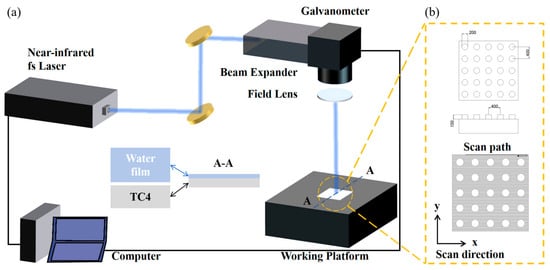
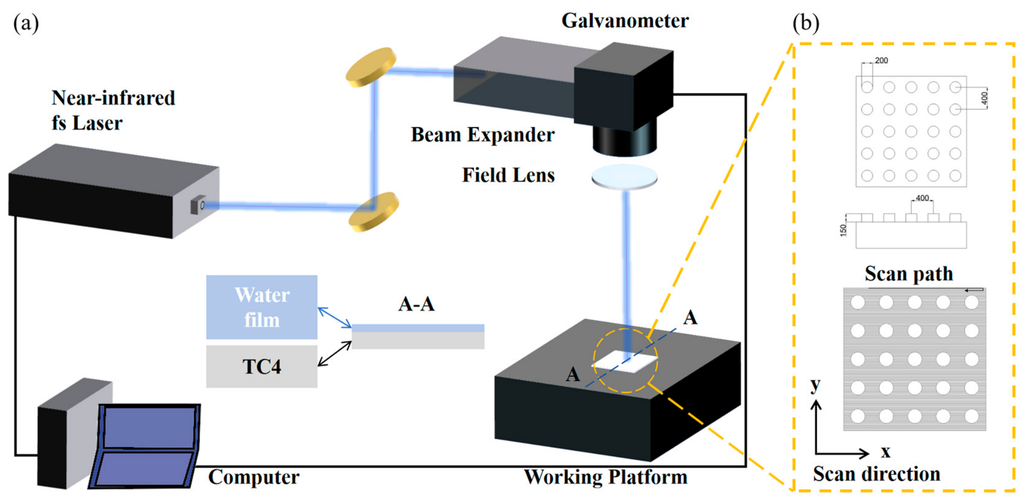
Figure 1 shows the laser processing setup used for surface texturing of TC4 titanium alloy. A home-built femtosecond laser system was employed as the laser source. The laser beam was steered by an external two-axis galvanometer scanner and focused onto the sample surface using focal-length lens. The TC4 specimen was fixed on an electrically controlled X–Y–Z translation stage to adjust the processing position. A computer motion-control system was used to coordinate the laser emission, galvanometer scanning, and stage movement.
Figure 1.
(a) Schematic diagram of the near-infrared femtosecond laser processing system; the blue lines represent the laser beam path. (b) Laser scanning pattern and trajectory within a 100 mm × 100 mm processing area, showing the scan path and scan direction along x-y axes.
The focal spot diameter was approximately 50 μm. The laser processing parameters are summarized in Table 1. To regulate the energy input during surface texturing, a fixed laser power of 6 W was used for all texturing experiments, and the scanning speed was adjusted from 125 to 500 mm/s.
Table 1.
The laser treatment parameters in this experiment.
Before laser irradiation, a thin deionized-water layer was introduced onto the polished TC4 surface using a spin coater. The water-assisted processing environment was employed to reduce thermal accumulation, remove ablation debris, and influence the formation of surface microstructures. In addition, the water layer helped attenuate excessive laser reflection and improve the uniformity of laser–material interaction.
As shown in Figure 1b, the laser-textured region was a 100 mm × 100 mm square area, processed with dense parallel scanning tracks. After laser treatment, the specimens were ultrasonically cleaned in absolute ethanol and deionized water for 10 min, respectively, to remove residual debris from the textured surface. Finally, the samples were dried with compressed nitrogen before further characterization and testing.
The femtosecond laser operated with a nominal pulse duration of ~280 fs according to the laser system specification. Based on the fixed laser parameters (6 W average power, 50 kHz repetition rate, ~50 μm focal spot diameter, Gaussian beam profile), the calculated single-pulse fluence at the focal plane was approximately 0.31 J/cm2 and the peak fluence was ~0.61 J/cm2. The laser beam was focused using an f-theta lens with a focal length of 160 mm; the focused spot diameter at the focal plane was approximately 50 μm (1/e2 diameter). During processing, the specimen surface was positioned at the focal plane of the f-theta lens.
All specimens were stored in ambient laboratory conditions after laser processing. Wettability measurements (contact angle) were performed 7–10 days after laser texturing to allow the surface chemistry to reach a quasi-stable state, as the laser-induced surface oxides and adsorbed hydrocarbon contaminants are known to influence wettability over the initial days following processing [27,29].
2.3. Characterizations and Measurements
The surface morphology of the TC4 specimens was characterized by scanning electron microscopy (SEM) to examine the microstructural changes induced by different laser processing parameters. Three-dimensional surface profiles, height variations, surface roughness, and the distribution of laser-patterned microstructures were obtained using laser confocal microscopy.
The wettability of the four types of surfaces was evaluated using a contact angle meter (OCA15EC). Static water contact angle was measured at room temperature, and the reported values were obtained by averaging five independent measurements taken at different positions on each sample. Before each test, the test equipment was cleaned with ethanol, and the specimens were ultrasonically cleaned in deionized water to remove residual dust and solid contaminants. All tests were performed at room temperature, except for the low-temperature icing experiments.
For contact angle measurements and freezing delay tests, deionized water droplets with a volume of 4.0 μL were dispensed via an electronically controlled injection device for precise volume regulation. The droplet and ambient temperatures were equilibrated to the target subzero temperature (−5, −10, and −15 ± 0.5 °C) within the temperature-controlled chamber prior to each icing test. The relative humidity inside the test chamber was maintained at 60 ± 5% throughout all icing and de-icing experiments.
Freezing onset was defined as the first visible appearance of opacity at the droplet apex (indicating ice nucleation), and complete freezing was defined as the point at which the entire droplet became opaque with no remaining transparent liquid region, as determined from sequential optical images. Complete ice detachment was defined as the moment when the ice layer visibly separated from and slid off the specimen surface under gravity, confirmed by optical imaging. Partial detachment or cracking without shedding was not counted as complete detachment.
For de-icing experiments, ice layers were prepared on the 10 cm × 10 cm TC4 specimens using a silicone ice mold with 60 mL of deionized water to ensure comparable ice formation conditions across all specimens. The resulting ice layer had an approximate thickness of 6 mm. For electrothermal de-icing tests, a constant DC voltage of 54 V was applied to the resistive heating element attached to the back surface of the TC4 specimen (measured current 1.8 A), corresponding to an input power of approximately 97.2 W (power density 0.972 W/cm2 over the 100 mm × 100 mm specimen area). A resistive heating film (polyimide-insulated) was bonded to the entire back surface (100 mm × 100 mm) of each TC4 specimen using thermally conductive adhesive, providing uniform heating across the specimen area. Icing (freezing delay) tests were performed with the specimen mounted horizontally (0° tilt). For electrothermal de-icing tests, the specimen was mounted at an angle of 30° with respect to the horizontal plane to facilitate gravity-assisted ice shedding.
Schematic diagrams of the self-built icing-delay test system and the electrothermal de-icing platform have been added as Figures S1 and S2 in the Supplementary Materials, showing the temperature-controlled chamber, droplet dispensing system, optical imaging setup, infrared camera arrangement, heating circuit, and data acquisition configuration.
The infrared imaging system was equipped with an automatic temperature correction function, which was performed periodically during measurement (every 10 s). All infrared images were acquired from a top-view perspective at a distance of approximately 30 cm from the specimen surface, with the infrared camera positioned perpendicular to the sample plane.
For each laser scanning speed condition (125, 250, 375, and 500 mm/s), one independent TC4 specimen (100 mm × 100 mm × 5 mm) was prepared under identical processing parameters. All characterizations were performed on these specimens. Static contact angle was measured at n = 5 different positions per specimen. Freezing delay behavior was evaluated through repeated experiments under identical conditions; electrothermal de-icing tests were conducted under repeated identical conditions. For contact angle and surface roughness measurements, where differences between groups are discussed, two-tailed Student’s t-tests with a significance threshold of p < 0.05 were applied. For freezing and de-icing experiments, results are reported as representative observations from repeated tests, and no statistical comparison of time-based metrics is claimed. The freezing process presented in the manuscript represents a characteristic measurement selected from repeated experiments under identical testing conditions, reflecting the consistent freezing delay trend induced by the laser-textured surface.
Static anti-icing performance was evaluated using a self-built icing-delay test system. The freezing delay time of water droplets on different TC4 surfaces was recorded under controlled low-temperature conditions. Electrothermal de-icing performance was investigated using a self-built static de-icing platform coupled with a signal acquisition system. During the de-icing process, the temperature response, de-icing time, and evolution of the ice–substrate interface were recorded. These measurements were used to analyze the effects of laser-patterned microstructures on wettability, icing delay, and electrothermal ice detachment behavior.
3. Results and Discussion
3.1. Surface Morphology
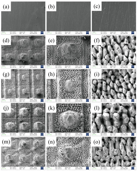
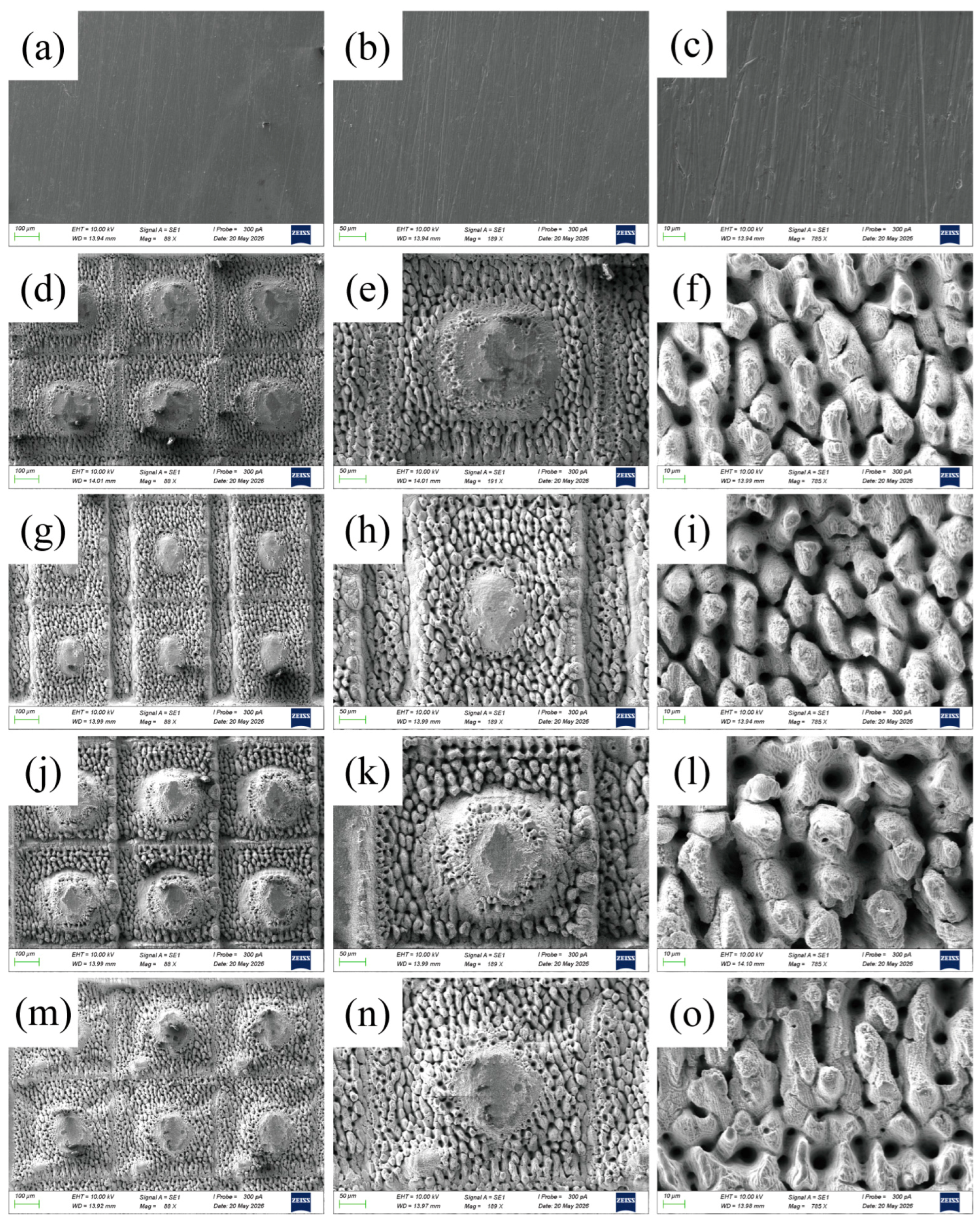
Figure 2 shows the SEM morphologies of untreated TC4 and laser-treated samples prepared at different scanning speeds. The untreated TC4 surface is relatively smooth, with only slight polishing scratches and no obvious microstructural features (Figure 2a–c). After laser processing, periodic cylindrical microstructures, ablated grooves, pores, and recast regions are formed on the TC4 surface, and their distribution varies markedly with scanning speed (Figure 2d–o).
Figure 2.
SEM images of the untreated TC4 (a–c), laser-treated TC4 with the speed of 125 mm/s (d–f), laser-treated TC4 with the speed of 250 mm/s (g–i), laser-treated TC4 with the speed of 375 mm/s (j–l), laser-treated TC4 with the speed of 500 mm/s (m–o).
At lower scanning speed, stronger local melting and material accumulation occur around the cylindrical regions, while increasing the scanning speed changes the degree of ablation, groove continuity, pore distribution, and the boundary between processed and retained regions. These morphology changes directly affect the size and distribution of air cavities between the surface and water/ice, which may further influence interfacial heat transfer during electrothermal anti-/de-icing. The scanning speed plays a key role in controlling local melting behavior, surface pattern distribution, and the microstructural features around the retained cylindrical regions.
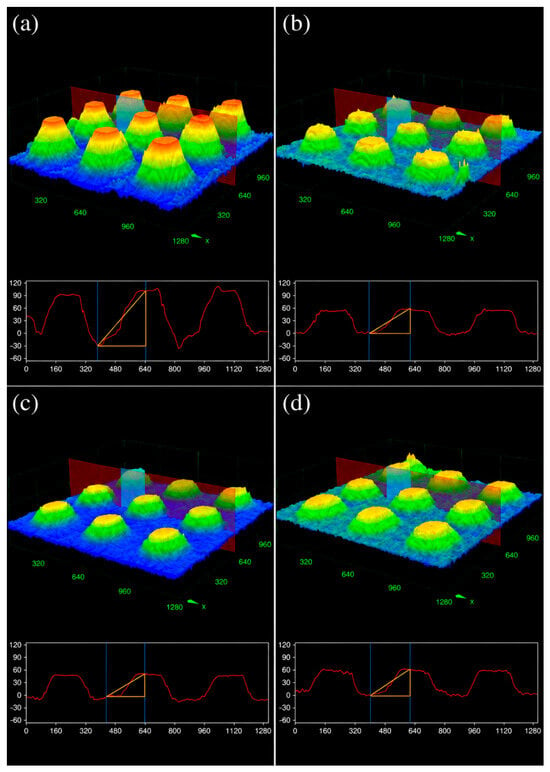
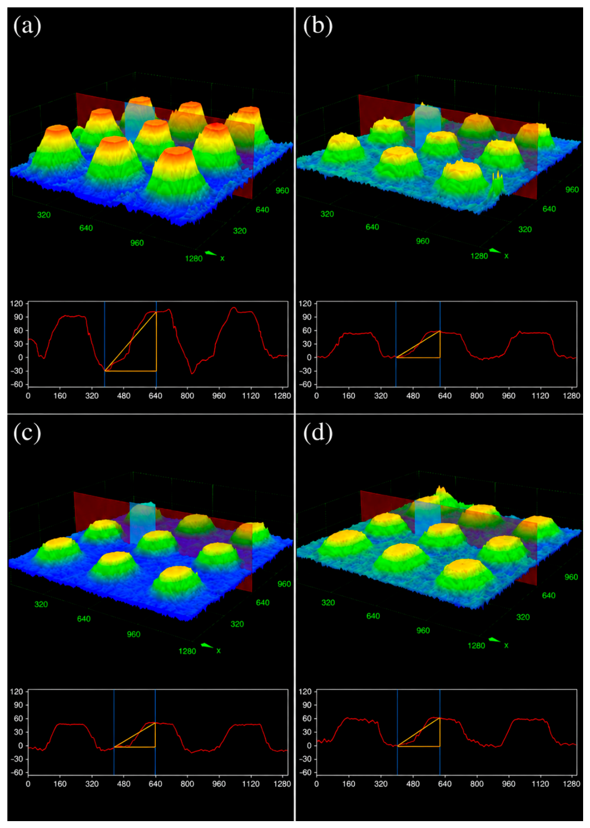
Quantitative analysis of the micro-cylinder diameters, obtained from CLSM cross-sectional profiles, reveals a non-monotonic variation with scanning speed. The measured mean diameters (±standard deviation) are: 143 ± 28 μm at 125 mm/s, 118 ± 15 μm at 250 mm/s, 105 ± 19 μm at 375 mm/s, and 91 ± 22 μm at 500 mm/s. This non-monotonic variation in cylinder diameter can be attributed to the interplay of two laser–matter interaction mechanisms that operate with different relative contributions across the scanning speed range: (i) Ablation-driven material removal, where the femtosecond laser pulse energy ablates material along the scanning tracks, defining the grooves that separate adjacent micro-cylinders (at higher scanning speeds, the reduced laser energy density per unit area and lower spot overlap ratio decrease the ablation width, tending to produce larger-diameter cylinders), and (ii) melting-driven material redistribution, where the accumulated heat at lower scanning speeds promotes localized melting and resolidification, causing material to flow and accumulate around the cylinder periphery, which increases the apparent cylinder diameter. At low speeds (125 mm/s), melting-driven accumulation dominates, producing the largest diameters (143 μm). At intermediate speeds (250–375 mm/s), reduced melting and moderate ablation narrow the cylinders (118–105 μm). At the highest speed (500 mm/s), minimal ablation and low spot overlap produce the smallest and most irregular cylinders (91 μm), but with increased variability reflecting the stochastic nature of weak ablation at high speed. The corresponding three-dimensional surface morphologies and cross-sectional profiles are shown in Figure 3.
Figure 3.
Surface morphologies of TC4 alloy at different laser scanning speeds: (a) 125 mm/s, (b) 250 mm/s, (c) 375 mm/s, (d) 500 mm/s. The color gradient represents surface height, and the lower-panel curves denote 2D cross-section profiles of the micro-structures.
The surface morphology and geometrical characteristics of the laser-treated TC4 samples were further examined using confocal laser scanning microscopy (CLSM). Three-dimensional topography and quantitative structural parameters were obtained to evaluate the influence of laser scanning speed on surface evolution.
Prior to laser processing, the polished TC4 surfaces exhibited only minor scratches and defects, appearing overall smooth. After femtosecond laser treatment, the surfaces developed complex microstructures characterized by isolated protrusions and interconnecting grooves. Structures fabricated under identical processing conditions displayed uniform size and shape, whereas the groove geometry between adjacent protrusions varied with scanning speed. At higher scanning speeds, the grooves adopted an inverted V-shape, reflecting limited energy dispersion in Figure 3a. In contrast, lower scanning speeds produced grooves with an inverted trapezoidal cross-section, resulting from larger continuous ablation within each laser period in Figure 3d.
Additionally, numerous microscale and nanoscale spikes formed on the surface and sidewalls of the protrusions due to localized melting and resolidification, contributing to a composite microstructure. These features were arranged in a relatively regular and ordered pattern across the treated surface.
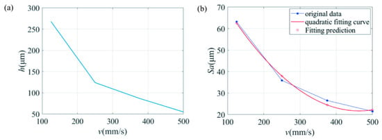
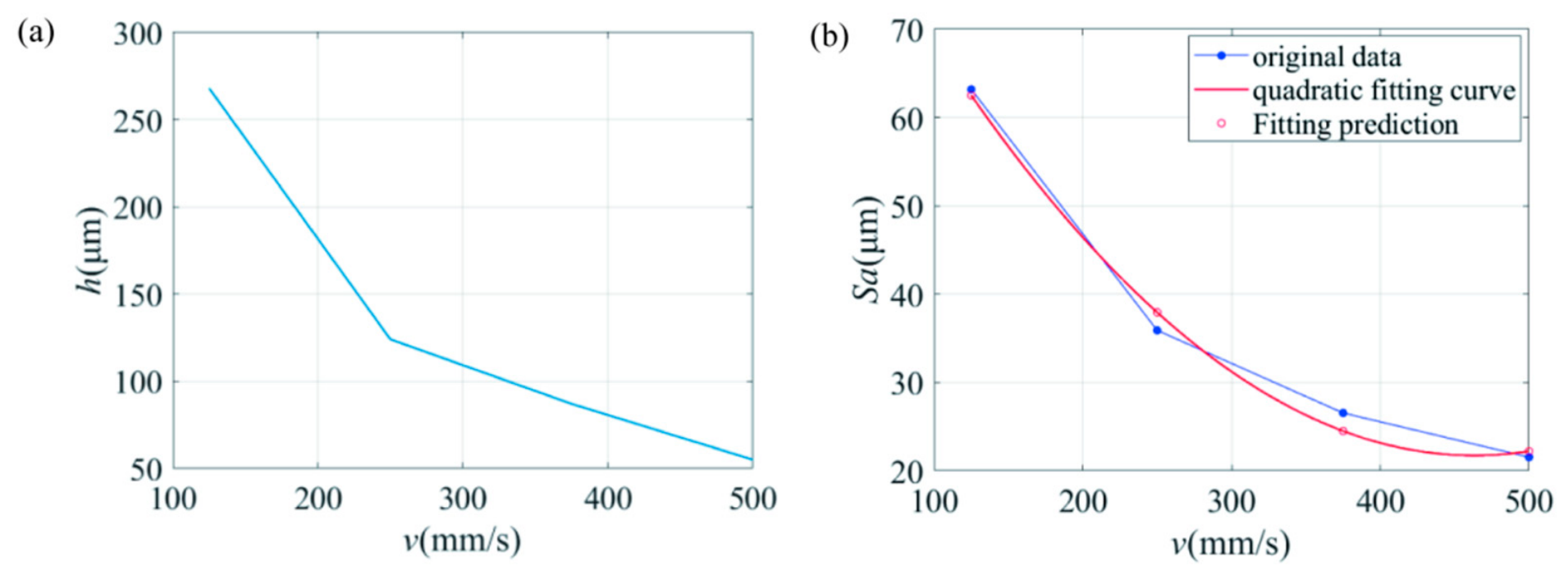
The variations in micro-cylinder height and surface roughness with laser scanning speed are summarized in Figure 4.
Figure 4.
(a) Micro-cylinder height and (b) surface roughness (Sa) of micro-cylindrical structures fabricated on TC4 alloy surface at different laser scanning velocities (v). The scattered points represent original experimental data, and solid lines denote quadratic fitting curves.
As shown in Figure 4a, the height of the micro-cylindrical structures gradually decreases with increasing laser scanning speed. At a scanning speed of 125 mm/s, the maximum height of the micro-cylinders reaches 268 μm. When the scanning speed increases to 250 mm/s, the height decreases to 124 μm, corresponding to 46.3% of the value obtained at 125 mm/s. With further increases in scanning speed to 375 mm/s and 500 mm/s, the heights decrease to 87 μm and 55 μm, accounting for 32.5% and 20.5% of the initial value, respectively. This trend can be attributed to the decrease in laser energy density per unit area at higher scanning speeds, which reduces the ablation and material removal rates, thereby limiting the vertical development of the micro-cylindrical structures.
Meanwhile, the surface roughness measurements, shown in Figure 4b, indicate that the maximum surface roughness of 63.187 μm is obtained at 125 mm/s. When the scanning speed increases to 250 mm/s, the roughness decreases to 35.9 μm, corresponding to 56.8% of the maximum value. At scanning speeds of 375 mm/s and 500 mm/s, the surface roughness further decreases to 26.547 μm and 21.541 μm, respectively, which are 42.0% and 34.1% of the value obtained at the lowest scanning speed. The surface roughness shows a nonlinear negative correlation with scanning speed and decreases as the scanning speed increases. This behavior indicates that the reduced laser energy density and lower spot overlap ratio decrease the ablation efficiency and suppress the vertical height of the fabricated micro-cylindrical protrusions.
To quantitatively describe the relationship between scanning speed and surface roughness, the experimental data were fitted using a quadratic polynomial based on the least-squares method. The obtained fitting equation captures the nonlinear variation in surface roughness with laser scanning speed and reflects the intrinsic relationship between surface morphology evolution and processing parameters, as expressed in Equation (1).
Sa = 0.000356v2 − 0.330243v + 98.21775
3.2. Surface Hydrophobicity and Droplet Freezing Behavior
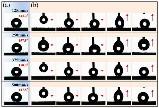
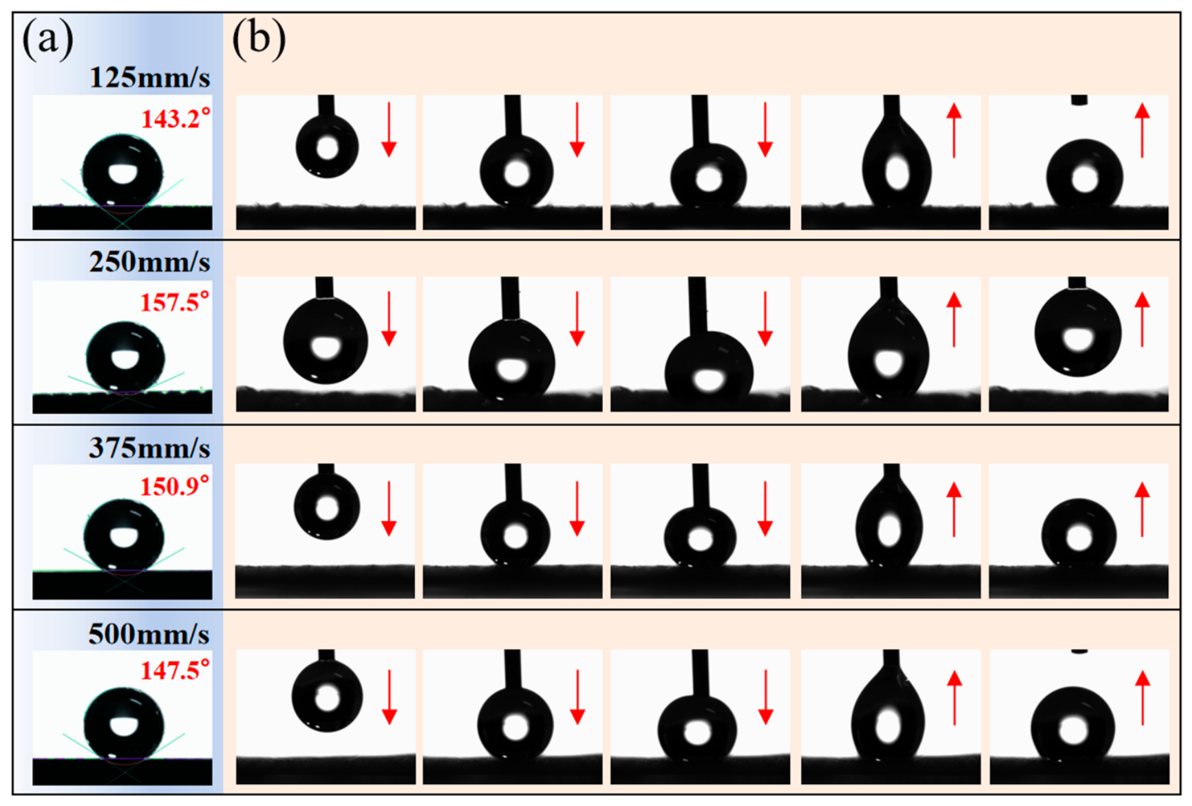
Figure 5 presents the wettability and dynamic droplet behavior of TC4 surfaces processed at different laser scanning speeds. The untreated TC4 surface is hydrophilic, with water contact angles of approximately 50–65°. After laser texturing, the contact angles increase significantly, and all treated surfaces exhibit hydrophobic behavior. As shown in Figure 5a, the contact angle rises from 143.2 ± 1.5° at 125 mm/s to 157.5° at 250 mm/s, and then decreases to 150.9° and 147.5° at 375 and 500 mm/s, respectively.
Figure 5.
Dynamic stretching and detachment behavior of water droplets on TC4 microstructured surfaces fabricated at 125 mm/s, 250 mm/s, 375 mm/s, and 500 mm/s processing speeds: (a) static water contact angle images; (b) needle-assisted droplet contact-retraction sequence, illustrating the adhesion behavior during forced contact and withdrawal. Downward arrows represent droplet compression, upward arrows represent droplet retraction; colored lines denote the contact-angle fitting baselines.
We note that the reported static contact angles provide an incomplete characterization of surface wettability. Advancing and receding contact angles, together with contact-angle hysteresis (CAH), would offer a more comprehensive assessment of droplet adhesion and mobility on these surfaces. Qualitative observations of droplet behavior under tilting conditions suggest that the 250 mm/s surface exhibits the lowest droplet pinning among all tested conditions, consistent with the needle-assisted retraction results shown in Figure 5b. Quantitative advancing/receding contact angle measurements represent a valuable direction for future wettability characterization of these surfaces.
The variation in wettability is related to both the height and spatial distribution of the micro-cylindrical structures. As shown in Figure 4a, the cylinder height decreases with increasing scanning speed. At 125 mm/s, the cylinders reach the maximum height, but pronounced local melting and material accumulation around the cylinders result in an uneven surface morphology, which may enhance local droplet pinning. At 250 mm/s, the cylinders maintain sufficient height and the surrounding grooves and processed regions are more uniformly distributed. This arrangement helps maintain air beneath the droplet and reduces the effective solid–liquid contact area, resulting in the highest apparent contact angle. When the scanning speed increases to 375 and 500 mm/s, the reduced cylinder height weakens the air retention between the droplet and the textured surface, increasing the droplet contact with grooves and processed regions and causing a decrease in contact angle.
Dynamic droplet tests, shown in Figure 5b, confirm these trends. The 250 mm/s surface exhibits a smaller droplet contact area, a more spherical droplet shape, and a more pronounced retraction response, indicating lower liquid adhesion. In contrast, droplets on the 125, 375, and 500 mm/s surfaces display greater deformation and weaker retraction behavior. These results demonstrate that wettability is determined not only by the cylinder height but also by the combined effect of cylinder height, groove distribution, and the stability of air cavities at the solid–liquid interface. It is noteworthy that a high static contact angle does not necessarily guarantee effective dynamic water repellency. For example, the 375 mm/s surface reaches the superhydrophobic range in terms of static contact angle, but reduced cylinder height and excessive surface asperities prevent the formation of effective microstructural units, limiting its dynamic hydrophobic performance.
The needle-assisted contact-retraction test qualitatively probes the adhesion between the droplet and the surface: a more complete retraction with minimal residual liquid on the surface indicates lower solid–liquid adhesion. While this test does not directly measure spontaneous rebound (which would require free-fall droplet impact), it provides a useful qualitative comparison of relative droplet adhesion across surfaces.
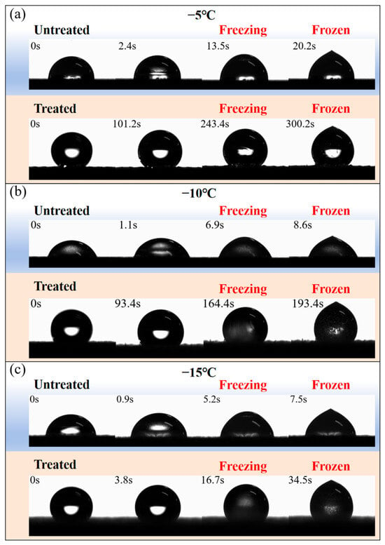
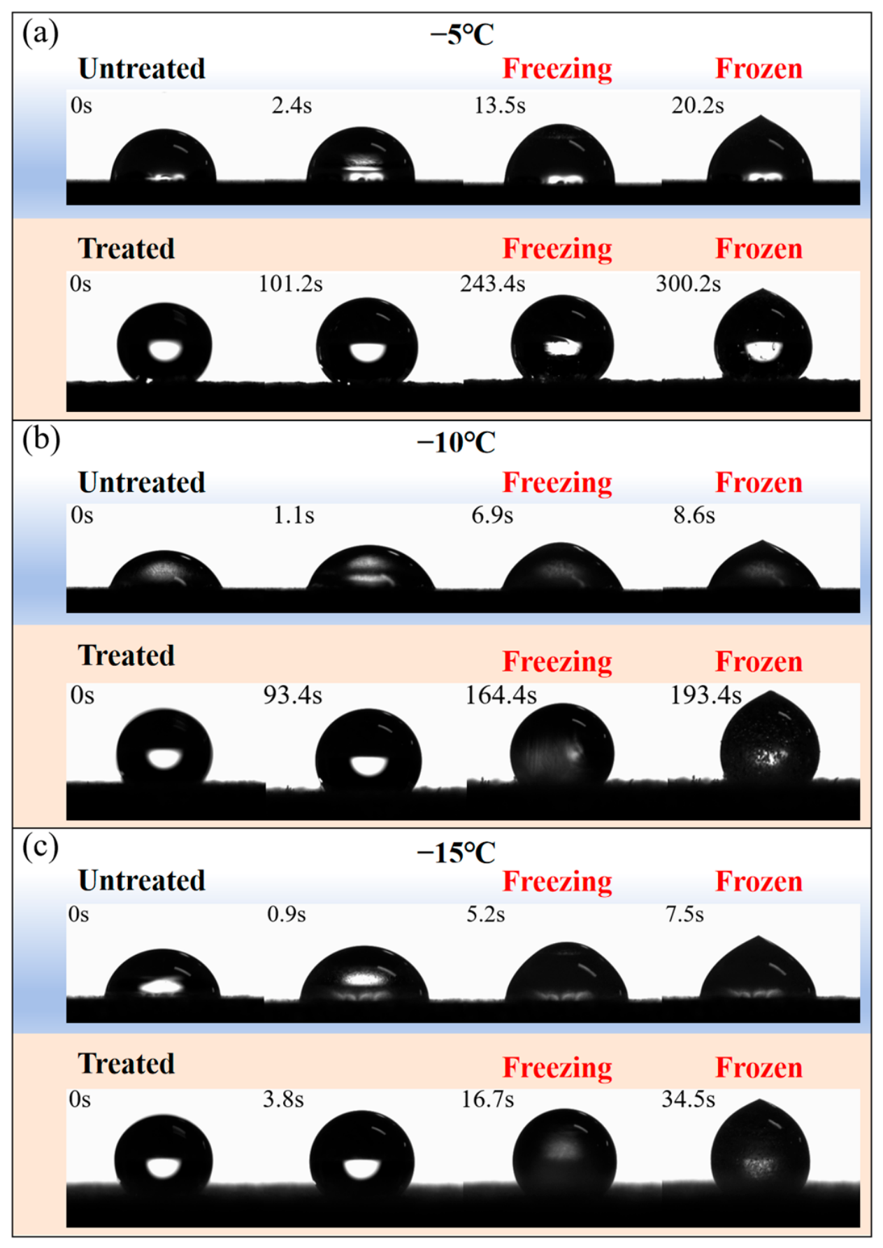
The freezing behaviors of water droplets on untreated and laser-treated TC4 surfaces at different subzero temperatures are compared in Figure 6.
Figure 6.
Comparison of the icing process of water droplets on untreated and laser-treated (250 mm/s) TC4 surfaces at different subzero temperatures. Sequential optical images of water droplets during freezing on untreated and treated surfaces at (a) −5 °C, (b) −10 °C, and (c) −15 °C. Red text labels denote the critical time points of the freezing procedure.
Figure 6 shows the freezing behavior of water droplets on untreated and laser-treated (250 mm/s) TC4 surfaces at −5, −10, and −15 °C. On the untreated TC 4 surface, the droplets spread more readily and freeze rapidly at all tested temperatures. In contrast, droplets on the laser-treated surface maintain a more spherical shape with a smaller apparent contact area, in agreement with the wettability results in Figure 5.
At −5 °C, the freezing onset and complete freezing times on untreated TC4 are 13.5 s and 20.2 s, respectively. After laser treatment (250 mm/s), these values increase to 243.4 s and 300.2 s, with the complete freezing time extended by approximately 14.9 times. At −10 °C, the complete freezing time increases from 8.6 s to 193.4 s, corresponding to an approximately 22.5 fold increase. At −15 °C, freezing is accelerated on both surfaces, but the laser-treated surface still delays freezing; the onset and complete freezing times increase from 5.2 s and 7.5 s to 16.7 s and 34.5 s, respectively.
The delayed freezing can be explained by the contact state between the droplet and the textured surface. The retained micro-cylindrical regions support the droplet, while the grooves between adjacent structures trap air at the interface. This reduces the actual solid–liquid contact area and weakens heat transfer from the droplet to the substrate. The discontinuous contact also decreases the number of effective heterogeneous nucleation sites. As the temperature decreases, the higher degree of supercooling shortens the freezing process, so the delay effect becomes less pronounced. Nevertheless, the laser-treated surface shows a longer freezing time than untreated TC4 throughout the tested temperature range.
Repeated observations under identical testing conditions consistently showed the same freezing delay trend, and the freezing process presented in Figure 6 represents a characteristic measurement selected from these repeated experiments.
3.3. Electrothermal De-Icing Behavior
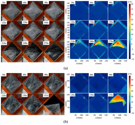
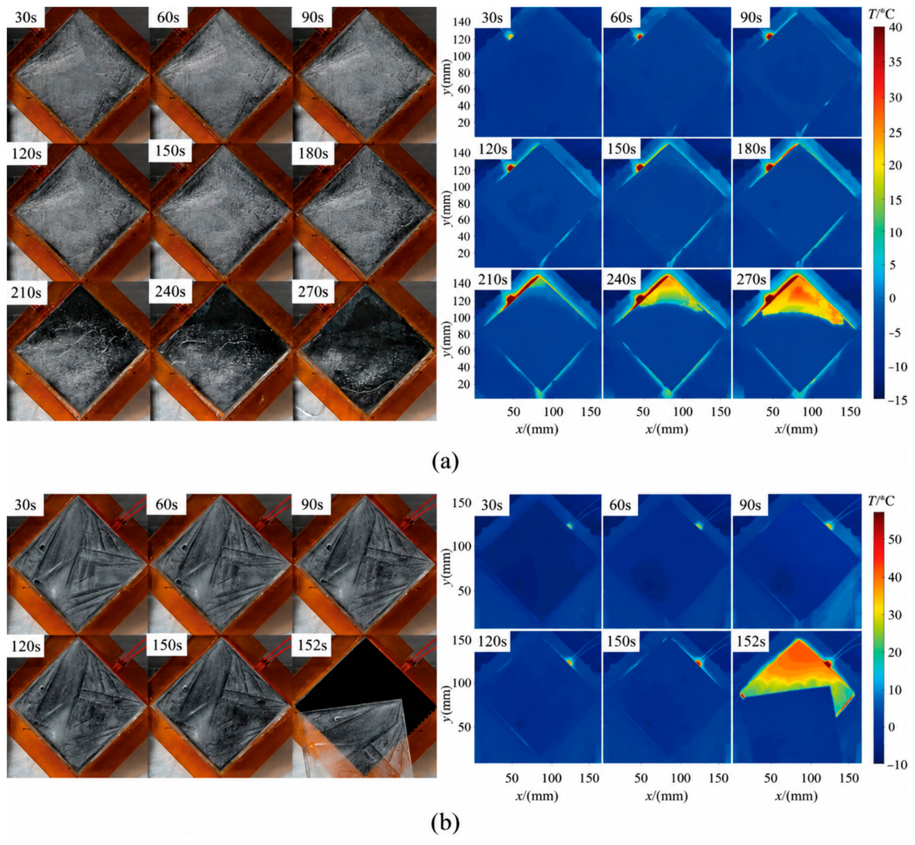
Although the laser-treated TC4 surface can passively delay droplet freezing, active de-icing is still necessary after ice accumulation. Therefore, electrothermal de-icing tests were performed to compare the ice-removal behavior of untreated and laser-treated TC4 surfaces, as shown in Figure 7.
Figure 7.
Electrothermal de-icing behavior of (a) untreated and (b) laser-treated (250 mm/s) TC4 surfaces, including optical images and corresponding infrared thermal images recorded at different heating times.
To further clarify the role of laser-patterned microstructures in electrothermal de-icing, the ice detachment process on untreated and laser-treated TC4 surfaces was recorded by optical imaging and infrared thermography under the same heating condition, as shown in Figure 7 At the initial stage, the ice layer is firmly attached to both surfaces. For the untreated TC4 surface, heat is mainly transferred through a continuous ice–substrate interface. Owing to the large real contact area and strong interfacial adhesion, the supplied heat is first consumed in gradually melting the ice near the substrate and forming a relatively continuous meltwater layer. This process is slow, and the generated meltwater is insufficient to trigger complete interfacial failure. As observed from the optical images, the ice layer still remains on the untreated surface after continuous heating for 270 s.
In contrast, the laser-treated surface shows a markedly faster de-icing response. During heating, localized melting first appears near the lower edge of the ice layer in the microstructured region, which agrees with the local temperature rise observed in the corresponding infrared images. As heating continues, the meltwater regions expand and connect along the ice–substrate interface, reducing interfacial adhesion and promoting ice detachment. Complete ice removal occurs at approximately 152 s.
The difference in de-icing behavior is hypothesized to arise from the laser-patterned surface morphology, which reduces the effective ice–substrate contact area. The retained micro-cylindrical structures and surrounding grooves reduce the effective ice–substrate contact area and introduce discontinuous contact at the interface. Under electrothermal heating, these contact regions act as preferential melting sites, while the trapped air and geometric discontinuities weaken heat transfer uniformity and facilitate local stress concentration. As a result, interfacial failure occurs earlier on the laser-treated surface. Compared with untreated TC4, the laser-treated surface enables faster ice shedding under the same heat input, indicating improved electrothermal de-icing efficiency.
Under the same applied electrical power of 97.2 W (54 V DC, 1.8 A), the laser-treated surface (250 mm/s) achieved complete ice detachment at approximately 152 s, whereas ice remained adhered to the untreated surface after 270 s of continuous heating. The estimated total energy input to the point of detachment on the laser-treated surface was approximately 14.58 kJ (97.2 W × 150 s), while the untreated surface consumed at least 26.24 kJ (97.2 W × 270 s) without achieving detachment. Normalized by the iced area, the energy to detachment on the laser-treated surface was approximately 0.146 kJ/cm2, compared with >0.262 kJ/cm2 for the untreated surface. It should be noted that the untreated surface had not achieved ice detachment at the termination of the 270 s observation period. Therefore, the de-icing time reduction is reported as a lower bound: the laser-treated surface achieves complete detachment in at most 152 s, while the untreated surface requires more than 270 s, corresponding to a minimum de-icing time reduction of 44%. We recognize that extending the untreated-surface test to complete detachment would provide a more precise baseline for quantifying the improvement. The 270 s test duration was governed by the pre-set safety limit of the heating platform to prevent substrate overheating and potential damage to the test setup. Under this constraint, the reported lower-bound value represents a conservative estimate of the actual improvement.
We note an important methodological limitation: the top-view infrared images in Figure 7 represent the apparent surface temperature of the ice layer, which is influenced by the thermal resistance of the ice itself. The temperature at the buried ice–substrate interface, where melting initiates, is expected to be higher than the ice surface temperature recorded by the IR camera. Therefore, the infrared images should be interpreted as qualitative indicators of the spatial distribution of heating rather than as direct measurements of interfacial temperature. The infrared images in Figure 7 are displayed using a common temperature scale of −10 °C to +15 °C for both untreated and treated surfaces to enable direct thermal comparison.
3.4. Mechanism Analysis
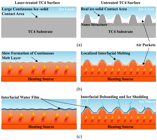
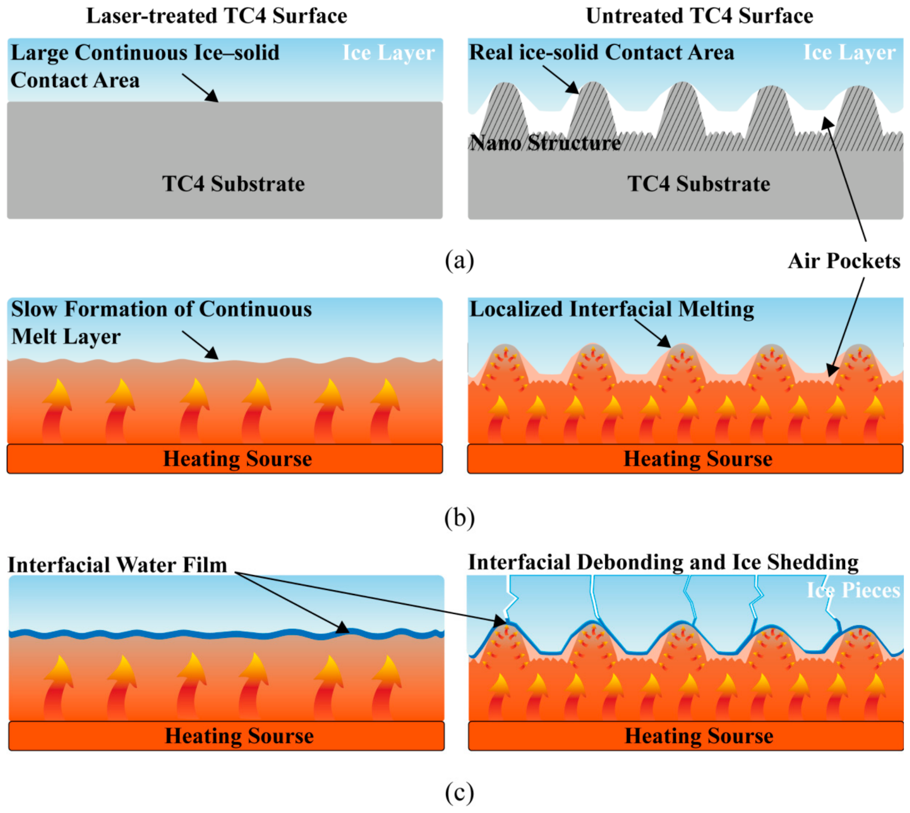
Based on the experimental observations reported above, we propose the following mechanistic hypotheses for the role of laser-patterned microstructures in electrothermal de-icing. These electrothermal de-icing mechanisms are schematically illustrated in Figure 8. We emphasize that these mechanisms are inferred from indirect evidence (SEM morphology, contact angle, freezing delay, and top-view IR thermography) and have not been directly validated by interfacial visualization or quantitative adhesion measurements. The comparison indicates that the laser scanning speed strongly affects the morphology of the laser-patterned microstructures and the local melting behavior. These changes further influence surface wettability, ice adhesion, and electrothermal de-icing performance. Among all tested conditions, the surface processed at 250 mm/s shows the highest water contact angle and the most stable dynamic droplet response, suggesting it as a promising candidate for anti-/de-icing applications.
Figure 8.
Schematic illustration of the electrothermal de-icing mechanism of ice-covered untreated and laser-treated TC4 surfaces: (a) initial ice–solid interfacial contact, (b) interfacial heat-transfer evolution under electrothermal heating, and (c) formation of an interfacial meltwater film and ice debonding/shedding.
On the one hand, the laser-induced microstructures are hypothesized to change the contact mode between ice and the substrate. On untreated TC4, the ice layer is expected to form a continuous interface with the smooth substrate, resulting in a large real contact area and strong adhesion. In contrast, on the laser-treated surface, the ice–substrate contact is proposed to be mainly confined to the tops of the micro-protrusions, while the recessed regions and nanoscale cavities reduce the effective contact area. This discontinuous contact weakens mechanical interlocking and lowers the interfacial bonding strength between the ice layer and the substrate.
On the other hand, during active electrothermal de-icing, ice removal from the untreated surface requires heat input over a large and continuous interface to form an interfacial melt layer. For the laser-treated surface, it is hypothesized that melting starts preferentially at the discrete contact points on the microstructures. The generated meltwater regions then expand and merge into a lubricating layer, which rapidly reduces the interfacial shear strength and promotes ice removal. In addition, the geometric discontinuities of the microstructured surface are proposed to, together with the thermal mismatch between ice and the TC4 substrate, promote local stress concentration and crack propagation, accelerating interfacial failure.
Overall, the improved de-icing performance of the laser-treated surface is hypothesized to arise from the combined effects of reduced ice adhesion, localized interfacial melting, and accelerated interface failure. The microstructures are proposed not to simply enhance heat transfer. Instead, they reduce the effective ice–substrate contact area and decrease the heat required to initiate ice detachment, allowing faster ice shedding than on the untreated surface. By adjusting the laser processing parameters, the surface morphology and local ablation/remelting degree can be controlled, providing a feasible route for tailoring the anti-icing and de-icing performance of titanium alloy surfaces.
(a) Reduced ice–substrate contact area and Cassie–Baxter wetting state. Observation: SEM imaging (Figure 2) reveals retained micro-cylindrical regions separated by interconnected grooves; static contact angle measurements confirm a transition from hydrophilic (untreated, ~50–65°) to superhydrophobic (treated, up to 157.5°). Hypothesized mechanism: The micro-cylindrical structures support the droplet/ice in a Cassie–Baxter state, with air trapped in the recessed grooves reducing the real solid–liquid and solid–ice contact area. This discontinuous contact may weaken mechanical interlocking at the ice–substrate interface. Literature support: This interpretation is consistent with findings by Memon et al. (2021) [26], Chen et al. (2024) [30], and Huré et al. (2022) [44], who independently reported that surface microtexturing reduces ice–substrate contact area and lowers ice adhesion through air-cavity stabilization at the interface.
(b) Localized interfacial melting at discrete contact points. Observation: Infrared thermography (Figure 7) shows non-uniform temperature distribution on the laser-treated surface during early-stage heating, with localized temperature rise near the lower edge of the ice in the microstructured region, preceding bulk melting. Hypothesized mechanism: Under electrothermal heating, the discrete ice–substrate contacts at the tops of micro-protrusions act as preferential thermal pathways, where melting initiates before spreading to recessed regions. The resulting meltwater regions expand and coalesce into a lubricating film that reduces interfacial shear strength. Literature support: This hypothesis aligns with reports by Pan et al. (2021) [28] and Zhao et al. (2022) [45], who reported that electrothermal de-icing on microstructured surfaces proceeds via preferential melting at asperity tips, where local thermal resistance is lowest.
(c) Stress concentration and interfacial crack propagation. Observation: Optical imaging during de-icing (Figure 7) shows crack formation initiating near the ice edge on the laser-treated surface, followed by rapid crack propagation and ice detachment, whereas the untreated surface exhibits gradual melting without visible fracture. Hypothesized mechanism: Geometric discontinuities at the microstructured interface, combined with the thermal expansion mismatch between ice and the TC4 substrate (α_ice ≈ 50 × 10−6/K vs. α_TC4 ≈ 8.6 × 10⁻⁶/K), may generate localized stress concentrations at the ice–substrate contact perimeter. These stresses may promote Mode-I crack initiation and propagation along the interface, accelerating ice detachment. Literature support: Dawood et al. (2023) [27] characterized ice adhesion fracture in Mode-I and Mode-II configurations, showing that interfacial geometric discontinuities reduce the effective fracture toughness and promote crack initiation at lower applied loads.
(d) Meltwater film lubrication and interfacial weakening. Observation: On the laser-treated surface, complete ice shedding occurs rapidly (~152 s) once meltwater regions become visible, whereas on the untreated surface, meltwater accumulates without triggering detachment within 270 s. Hypothesized mechanism: The combination of reduced initial contact area and localized melting enables a thin, continuous meltwater film to form more rapidly on the microstructured surface. This film may act as a lubricating layer that reduces interfacial shear strength, enabling gravity-driven ice shedding at a lower cumulative thermal input than would be required for complete interfacial melting on a smooth surface. Literature support: This mechanism is consistent with studies by Xu et al. (2024) [21] and Li et al. (2022) [24], who reported that a thin interfacial meltwater film can reduce ice adhesion strength by an order of magnitude under dynamic heating conditions.
Regarding the durability of the laser-induced microstructures, we note that the micro-cylindrical structures fabricated on TC4 in this study are integral to the bulk substrate, produced by localized ablation and resolidification of the Ti-alloy itself. This is a fundamental durability advantage over polymer-based or particle-filled coatings, where interfacial delamination between the coating and substrate is a common failure mechanism under thermal cycling and erosion. Published studies on laser-textured Ti-alloy surfaces consistently report that femtosecond-laser-induced microstructures retain their functional properties under moderate mechanical loads: Lian et al. [33] reported that femtosecond-laser-textured superhydrophobic Ti6Al4V surfaces retained water contact angles above 150° after 20 abrasion cycles under 2 kPa pressure, and Xu et al. [31] demonstrated that laser-textured and micro-arc-oxidized TC4 surfaces maintained superhydrophobicity after 50 tape-peeling cycles and 120 min of water-jet impact. Chen et al. [41] further demonstrated that hierarchical micro-nano structures on metallic substrates sustain icephobic performance over multiple freeze–thaw cycles, with surface morphology and wettability remaining stable. Based on these literature precedents, the present microstructures are expected to exhibit qualitatively similar mechanical and environmental robustness. However, we acknowledge that the present study does not include direct durability characterization. Dedicated durability testing under application-relevant conditions is essential to validate the practical viability of the proposed approach and is identified as a key future research priority.
4. Conclusions
This study investigated the effects of femtosecond-laser-fabricated microstructures on the surface morphology, static wettability, and electrothermal de-icing behavior of TC4 surfaces at different scanning speeds. The main conclusions are summarized as follows:
Laser scanning speed strongly affects the surface morphology and physical characteristics of TC4. The scanning speed determines the morphology of the laser-patterned microstructures, while the local ablation degree affects their geometric features. Laser processing also modifies the surface composition and microstructure of TC4. Among the tested conditions, the surface processed at 250 mm/s exhibited the most favorable combination of morphology and wettability, with sufficient local ablation and well-developed microstructures. This surface exhibits the highest static water contact angle, improved dynamic droplet behavior, and reduced effective solid–liquid and ice–solid contact areas. Lower or higher scanning speeds lead to less desirable structures due to excessive melting or incomplete pattern formation.
- (1)
- The microstructures change the ice–substrate contact mode. On untreated TC4, the ice layer forms a continuous interface with the smooth substrate. In contrast, on laser-treated surfaces, ice contact is mainly confined to the tops of the micro-protrusions, while the recessed regions reduce the effective contact area. This discrete contact weakens mechanical interlocking and lowers the interfacial bonding strength, thereby delaying ice nucleation and improving anti-icing performance.
- (2)
- Electrothermal de-icing is accelerated by localized interfacial melting and early interface failure. During Joule heating, melting starts preferentially at discrete contact points on the microstructured surface. The local meltwater regions expand and merge into a lubricating layer, which reduces interfacial shear strength and promotes ice detachment. Meanwhile, the air gaps at the interface reduce continuous ice–solid contact and facilitate interfacial instability during heating. Geometric discontinuities and thermal mismatch between ice and the TC4 substrate further promote crack initiation and interface failure, contributing to faster de-icing.
Overall, optimization of the laser processing parameters enables the formation of uniform microstructures on TC4 surfaces, improving hydrophobicity and reducing ice adhesion at the physical interface. When coupled with electrothermal heating, the microstructured surface promotes localized interfacial melting rather than requiring uniform melting over the entire ice–substrate interface, thereby reducing the time and total energy required for ice detachment under identical heating conditions, thereby improving de-icing efficiency relative to the untreated surface. This strategy provides a simple, economical, and efficient approach for enhancing the anti-icing and de-icing performance of titanium alloy surfaces, with potential applications in aerospace, wind energy, power transmission, and other fields requiring lightweight and compact ice-protection systems.
We note that the proposed de-icing mechanisms (discontinuous contact, localized interfacial melting, stress concentration, and crack propagation) are inferred from indirect morphological, thermal, and optical observations and are supported by published literature; direct validation through cross-sectional interfacial imaging and quantitative ice-adhesion measurements under controlled heating conditions is an important direction for future investigation. Future work should systematically evaluate the mechanical and functional durability of the laser-textured surfaces under simulated in-service conditions, including rain/particle erosion, cyclic thermal loading (−20 to +60 °C), UV exposure, and repeated icing/de-icing cycles. Long-term wettability stability under varying humidity and contamination conditions should also be assessed. Comprehensive icing/de-icing testing across all scanning speeds represents an additional important direction for future work. A complete energy-efficiency assessment would also require systematic power-variation experiments, ice mass normalization, and comparative benchmarking against alternative de-icing methods.
Supplementary Materials
The following supporting information can be downloaded at: https://www.mdpi.com/article/10.3390/aerospace13080738/s1. Figure S1: Schematic diagram of the experimental setup for observing droplet icing behavior under controlled temperature and humidity conditions; Figure S2: Schematic diagram of the experimental setup for electrothermal de-icing performance evaluation.
Author Contributions
J.R.: Conceptualization, Methodology, Investigation, Formal analysis, Data curation, Visualization, Writing—original draft. H.L. (Hua Liang): Supervision, Project administration, Funding acquisition, Resources, Writing—review & editing. B.W.: Methodology, Supervision, Validation, Resources, Writing—review & editing. Z.S.: Conceptualization, Methodology, Supervision, Validation, Writing—review & editing. H.L. (Hongrui Liu): Investigation, Formal analysis, Data curation, Validation, Writing—review & editing. X.Z.: Methodology, Supervision, Validation, Writing—review & editing. All authors have read and agreed to the published version of the manuscript.
Funding
This research was funded by the National Key Research and Development Program of China, grant number 2023YFB4605700; the National Natural Science Foundation of China (NSFC), grant numbers 52407190 and 12402332; and the National Key Laboratory Fund, grant number APSPT202302003. The APC was funded by the authors.
Data Availability Statement
The raw/processed data generated in this work will be made available upon reasonable request to the corresponding author.
Conflicts of Interest
The authors declare no conflicts of interest.
References
- Zhou, L.; Yi, X.; Liu, Q. A review of icing research and development of icing mitigation techniques for fixed-wing UAVs. Drones 2023, 7, 709. [Google Scholar] [CrossRef] [Scilit]
- Muhammed, M.; Virk, M.S. Ice accretion on rotary-wing unmanned aerial vehicles—A review study. Aerospace 2023, 10, 261. [Google Scholar] [CrossRef] [Scilit]
- Han, N.; Siddique, M.A.; Zhang, Z.; Tian, L.; Hu, H.; Hu, H. A flight-testing campaign to examine inflight icing characteristics and its effects on the flight performance of an unmanned-aerial-vehicle. Cold Reg. Sci. Technol. 2023, 207, 103775. [Google Scholar] [CrossRef] [Scilit]
- Karpen, N.; Diebald, S.; Dezitter, F.; Bonaccurso, E. Propeller-integrated airfoil heater system for small multirotor drones in icing environments: Anti-icing feasibility study. Cold Reg. Sci. Technol. 2022, 201, 103616. [Google Scholar] [CrossRef] [Scilit]
- Müller, N.C.; Løw-Hansen, B.; Borup, K.T.; Hann, R. UAV icing: Development of an ice protection system for the propeller of a small UAV. Cold Reg. Sci. Technol. 2023, 213, 103938. [Google Scholar] [CrossRef] [Scilit]
- Tu, J.; Tian, W.; Wang, X.; Tian, L. Experimental study on the effects of substrate hydro-/icephobicity on ice mitigation and ice shedding during the dynamic icing process over the rotating propeller of an unmanned-aerial-vehicle. Aerosp. Sci. Technol. 2024, 155, 109610. [Google Scholar] [CrossRef] [Scilit]
- Løw-Hansen, B.; Müller, N.C.; Coates, E.M.; Johansen, T.A.; Hann, R. Identification of an Electric UAV Propulsion System in Icing Conditions. SAE Technical Paper 2023-01-1378. 2023. Available online: https://saemobilus.sae.org/papers/identification-electric-uav-propulsion-system-icing-conditions-2023-01-1378 (accessed on 9 July 2026).
- Chen, L.; Xu, J.; Luo, X.; Liu, Z.; Wang, B.; Song, Q.; Cai, Y.; Wan, Y.; Gao, X.; Li, C. Micro/nano manufacturing aircraft surface with anti-icing and deicing performances: An overview. Nanotechnol. Rev. 2023, 12, 20230105. [Google Scholar] [CrossRef] [Scilit]
- Cong, Q.; Qin, X.; Chen, T.; Jin, J.; Liu, C.; Wang, M. Research progress of superhydrophobic materials in the field of anti-/de-icing and their preparation: A review. Materials 2023, 16, 5151. [Google Scholar] [CrossRef] [Scilit] [PubMed]
- Cui, Y.; Chen, W.; Dai, N.; Han, C. Integrated technologies for anti-deicing functions and structures of aircraft: Current status and development trends. Aerospace 2024, 11, 821. [Google Scholar] [CrossRef] [Scilit]
- Guo, C.; Liu, L.; Yang, R.; Lu, J.; Liu, S. Bouncing regimes of supercooled water droplets impacting superhydrophobic surfaces with controlled temperature and humidity. Langmuir 2023, 39, 10199–10208. [Google Scholar] [CrossRef] [Scilit] [PubMed]
- Wang, J.; Dhulipalla, A.; Zhao, Y.; Nunes, A.; Hu, H. An experimental investigation on dynamic water runback process over the blade surface of a rotating drone propeller. In AIAA Aviation Forum and Ascend 2025; AIAA 2025-3164; American Institute of Aeronautics and Astronautics, Inc.: Reston, VA, USA, 2025. [Google Scholar] [CrossRef] [Scilit]
- Wang, J.; Bowers, K.; Valentin, C.; Hu, H. An experimental study of droplet impinging dynamics on rotating UAV propellers under freezing rain conditions. In AIAA Aviation 2026 Forum; AIAA 2026-4355; American Institute of Aeronautics and Astronautics, Inc.: Reston, VA, USA, 2026. [Google Scholar] [CrossRef] [Scilit]
- Wang, J.; Frantz, J.; Chumbley, E.; Samad, A.; Hu, H. An explorative study on using carbon nanotube-based superhydrophobic self-heating coatings for UAV icing protection. Molecules 2025, 30, 3472. [Google Scholar] [CrossRef] [Scilit] [PubMed]
- Wang, J.; Dhulipalla, A.; Hu, H. An experimental study on the aerodynamic performance degradation of a high-lift UAV airfoil induced by ice accretion. In AIAA SciTech 2026 Forum; AIAA 2026-0887; American Institute of Aeronautics and Astronautics, Inc.: Reston, VA, USA, 2026. [Google Scholar] [CrossRef] [Scilit]
- Müller, N.C.; Villeneuve, E.; Hann, R. UAV icing: Experimental characterization of the performance impact of ice accretion on a propeller. Drones 2026, 10, 166. [Google Scholar] [CrossRef] [Scilit]
- Hatte, S.; Kant, R.; Pitchumani, R. Freezing characteristics of a water droplet on a multiscale superhydrophobic surface. Langmuir 2023, 39, 11898–11909. [Google Scholar] [CrossRef] [Scilit] [PubMed]
- Cui, J.; Wang, T.; Che, Z. Freezing–melting mediated dewetting transition for droplets on superhydrophobic surfaces with condensation. Langmuir 2024, 40, 14685–14696. [Google Scholar] [CrossRef] [Scilit] [PubMed]
- Liu, D.; Mahmood, A.; Sun, Y.; Wang, Q. Directional motion of water droplets enhances anti-icing failure of structural superhydrophobic surfaces. Surf. Interfaces 2024, 45, 103878. [Google Scholar] [CrossRef] [Scilit]
- Wang, L.; Shu, L.; Lv, Y.; Hu, Q.; Ma, L.; Jiang, X. Ultra-efficient and thermally-controlled atmospheric structure deicing strategy based on the Peltier effect. Appl. Therm. Eng. 2024, 248, 123162. [Google Scholar] [CrossRef] [Scilit]
- Xu, K.; Jiang, W.; Zhou, Z.; Li, Z.; Bai, T.; Xiong, H. Adhesive strength of ice on solid surfaces under dynamic heating condition. J. Adhes. Sci. Technol. 2024, 38, 3397–3412. [Google Scholar] [CrossRef] [Scilit]
- Wang, Y.; Xiong, K.; Zhu, C.; Zhu, C.; Chen, L. Evaluation of the shear adhesion strength of impact ice by a new method. Eng. Fract. Mech. 2023, 292, 109641. [Google Scholar] [CrossRef] [Scilit]
- Khodakarami, S.; Agarwal, V.; Kabirzadeh, P.; Solecki, A.; Hoque, M.J.; Yang, W.; Stokowski, N.; Jacobs, J.; Chatterji, A.; Lovelace, E.; et al. Aircraft electrothermal pulse deicing. ASME J. Heat Mass Transf. 2025, 147, 012401. [Google Scholar] [CrossRef] [Scilit]
- Li, L.; Khodakarami, S.; Yan, X.; Rabbi, K.F.; Gunay, A.A.; Stillwell, A.; Miljkovic, N. Enabling renewable energy technologies in harsh climates with ultra-efficient electro-thermal desnowing, defrosting, and deicing. Adv. Funct. Mater. 2022, 32, 2201521. [Google Scholar] [CrossRef] [Scilit]
- Esmaeilifar, E.; Raj, L.P.; Myong, R.S. Computational simulation of aircraft electrothermal de-icing using an unsteady formulation of phase change and runback water in a unified framework. Aerosp. Sci. Technol. 2022, 130, 107936. [Google Scholar] [CrossRef] [Scilit]
- Memon, H.; Mirshahidi, K.; Zarasvand, K.A.; Golovin, K.; De Focatiis, D.S.A.; Choi, K.-S.; Hou, X. Comparative study on the influence of surface characteristics on de-icing evaluation. J. Mater. Sci. 2021, 56, 17337–17352. [Google Scholar] [CrossRef] [Scilit]
- Dawood, B.; Yavas, D.; Bastawros, A.F. Ice adhesion characterization using mode-I and mode-II fracture configurations. J. Appl. Mech. 2023, 90, 121015. [Google Scholar] [CrossRef] [Scilit]
- Pan, R.; Zhang, H.; Zhong, M. Triple-scale superhydrophobic surface with excellent anti-icing and icephobic performance via ultrafast laser hybrid fabrication. ACS Appl. Mater. Interfaces 2021, 13, 1743–1753. [Google Scholar] [CrossRef] [Scilit] [PubMed]
- Gaddam, A.; Sharma, H.; Karkantonis, T.; Dimov, S. Anti-icing properties of femtosecond laser-induced nano and multiscale topographies. Appl. Surf. Sci. 2021, 552, 149443. [Google Scholar] [CrossRef] [Scilit]
- Chen, Z.; Song, L.; Wang, Y.; Tao, H.; Liu, Z.; Wang, T.; Ye, F.; He, Y.; Lin, J. Air pocket-optimization strategy for micro/nanostructures fabricated by femtosecond laser technology for anti-icing performance improvement. Appl. Surf. Sci. 2024, 655, 159454. [Google Scholar] [CrossRef] [Scilit]
- Xu, G.; Liu, P.; Liu, A.; Zhang, C.; Zhang, G.; Wu, Q.; Lu, H. Mechanically stable superhydrophobic surfaces constructed by laser surface texturing and micro-arc oxidation of TC4 alloy prepared based on SLM. Mater. Chem. Phys. 2024, 325, 129791. [Google Scholar] [CrossRef] [Scilit]
- Liu, M.; Yang, Z.; Dong, L.; Wang, Z.; Wang, S.; Wang, L.; Xie, Y.; Zhang, Q.; Weng, Z.; Tian, Y. Vacuum conditions for tunable wettability transition on laser ablated Ti-6Al-4V alloy surfaces. Colloids Surf. A Physicochem. Eng. Asp. 2022, 647, 129023. [Google Scholar] [CrossRef] [Scilit]
- Lian, Z.; Yang, J.; Wang, J.; Zhou, D.; Xu, J.; Yu, H. Texturing of superhydrophobic Ti6Al4V surfaces by dynamic water film assisted laser micromachining. Opt. Laser Technol. 2025, 181, 112044. [Google Scholar] [CrossRef] [Scilit]
- Xiao, P.; Chen, G.; Chen, Y.; Zhang, X.; Yuan, X. Morphology and wettability of titanium alloy surface textured by femtosecond laser. Chin. J. Lasers 2023, 50, 1602208. [Google Scholar] [CrossRef] [Scilit]
- Schell, F.; Alamri, S.; Hariharan, A.; Gebert, A.; Lasagni, A.F.; Kunze, T. Fabrication of four-level hierarchical topographies through the combination of LIPSS and direct laser interference pattering on near-beta titanium alloy. Mater. Lett. 2022, 306, 130920. [Google Scholar] [CrossRef] [Scilit]
- Liu, D.; Liu, R.; Cao, L.; Saeed, S.; Bryanston-Cross, P.J.; Wang, Z. Fabrication of periodic hierarchical structures with anti-icing performance by direct laser interference lithography and hydrothermal treatment. Surf. Coat. Technol. 2023, 471, 129819. [Google Scholar] [CrossRef] [Scilit]
- Wang, S.; Dong, S.; Liu, X.; Yan, S. Multifunctional surface of titanium alloy with dual-scale hierarchical micro/nanostructures fabricated by femtosecond laser processing. Opt. Laser Technol. 2023, 164, 109423. [Google Scholar] [CrossRef] [Scilit]
- Haryono, M.B.; Lin, K.W.Y.; Waritanant, T. Fast fabrication of superhydrophobic Ti-6Al-4V surface using Q-switched nanosecond pulsed laser at 1064 nm and cyclohexane. Heliyon 2024, 10, e37808. [Google Scholar] [CrossRef] [Scilit] [PubMed]
- Cui, J.; Wang, Y.; Wang, C.; Yang, G. Anti-icing and weatherability study of superhydrophobic titanium metal matrix composites surface. Colloid Interface Sci. Commun. 2024, 58, 100759. [Google Scholar] [CrossRef] [Scilit]
- Xuan, S.; Yin, H.; Li, G.; Zhang, Z.; Jiao, Y.; Liao, Z.; Li, J.; Liu, S.; Wang, Y.; Tang, C.; et al. Trifolium repens L.-like periodic micronano structured superhydrophobic surface with ultralow ice adhesion for efficient anti-icing/deicing. ACS Nano 2023, 17, 21749–21760. [Google Scholar] [CrossRef] [Scilit] [PubMed]
- Chen, C.; Tian, Z.; Luo, X.; Jiang, G.; Hu, X.; Wang, L.; Peng, R.; Zhang, H.; Zhong, M. Micro-nano-nanowire triple structure-held PDMS superhydrophobic surfaces for robust ultra-long-term icephobic performance. ACS Appl. Mater. Interfaces 2022, 14, 23973–23982. [Google Scholar] [CrossRef] [Scilit] [PubMed]
- Guo, C.; Zhang, M.; Hu, J. Icing delay of sessile water droplets on superhydrophobic titanium alloy surfaces. Colloids Surf. A Physicochem. Eng. Asp. 2021, 621, 126587. [Google Scholar] [CrossRef] [Scilit]
- He, Y.; Wang, L.; Wu, T.; Wu, Z.; Chen, Y.; Yin, K. Facile fabrication of hierarchical textures for substrate-independent and durable superhydrophobic surfaces. Nanoscale 2022, 14, 9392–9400. [Google Scholar] [CrossRef] [Scilit] [PubMed]
- Huré, M.; Olivier, P.; Garcia, J. Effect of Cassie-Baxter versus Wenzel states on ice adhesion: A fracture toughness approach. Cold Reg. Sci. Technol. 2022, 194, 103440. [Google Scholar] [CrossRef] [Scilit]
- Zhao, Z.; Chen, H.; Zhu, Y.; Liu, X.; Wang, Z.; Chen, J. A robust superhydrophobic anti-icing/de-icing composite coating with electrothermal and auxiliary photothermal performances. Compos. Sci. Technol. 2022, 227, 109578. [Google Scholar] [CrossRef] [Scilit]

Disclaimer/Publisher’s Note: The statements, opinions and data contained in all publications are solely those of the individual author(s) and contributor(s) and not of MDPI and/or the editor(s). MDPI and/or the editor(s) disclaim responsibility for any injury to people or property resulting from any ideas, methods, instructions or products referred to in the content. |
© 2026 by the authors. Licensee MDPI, Basel, Switzerland. This article is an open access article distributed under the terms and conditions of the Creative Commons Attribution (CC BY) license.