


Abstract
To address the structural deformation and mechanism jamming frequently observed in critical linkages during retraction and extension of door-coupled landing gear systems, this study proposes a rigid–flexible coupled dynamic modeling approach. A representative landing gear system was studied, and a high-fidelity rigid–flexible multibody dynamics model was developed based on a conventional rigid-body framework. The left linkage, which was prone to failure, was modeled as a flexible finite element component, while the remaining parts were treated as rigid bodies. A multibody dynamics method based on nonlinear finite element was adopted, incorporating elastoplastic constitutive relations and Lagrange constraint equations. Two materials, ultra-high-strength 300M steel and high-strength 7075-T6 aluminum alloy, were evaluated to investigate the influence of structural stiffness on critical linkage stress and door kinematics during deployment. Results showed that maximum stress occurred at the hinge joint, identified as the critical region for strength assessment. The peak stress for 300M reached approximately 168 MPa, about 8.4% higher than that of 7075-T6. However, 7075-T6 exhibited lower stress oscillation frequency and superior damping performance, which helped suppress high-frequency vibration. Material selection had negligible influence on door centroid displacement, velocity, and opening angle, and the motion trajectories remained highly consistent.
1. Introduction
The landing gear system is a critical functional subsystem that ensures the safety of aircraft during takeoff and landing, and the dynamic characteristics of its retraction and extension mechanisms directly affect mission reliability and operational safety [1,2]. Statistics indicate that, among civil aviation accidents caused by landing gear system failures over the past two decades, failures associated with the retraction and extension system have been the most frequent among all landing gear subsystems [3]. Owing to advantages such as high space utilization efficiency and simplified hydraulic architecture, door-coupled landing gear systems have been widely adopted in modern aircraft design. However, their spatial multi-link configurations are prone to motion incoordination and complex load transfer during retraction and extension, which may further induce linkage deformation and mechanism jamming, thereby posing a serious threat to flight safety [4,5]. Therefore, a thorough understanding of the dynamic behavior and failure mechanisms of these systems is of great significance for improving landing gear design and operational reliability.
Extensive studies have been conducted worldwide on the dynamic modeling of landing gear retraction and extension mechanisms. Yin et al. [6] established a coupled dynamic model of the landing gear retraction mechanism and hydraulic system based on the second kind of Lagrange equation and the power bond graph method, enabling coupled solutions for mechanism motion and hydraulic response. Shi et al. [7] investigated linkage deformation during the operation of a door-coupled mechanism by employing the Denavit–Hartenberg (D-H) coordinate transformation method and the second kind of Lagrange equation to establish kinematic and dynamic models. Their study revealed the failure mechanism in which abrupt variations in hinge torque induce linkage deformation, and the hinge spatial position and orientation were further optimized using a particle swarm optimization algorithm. Knowles et al. [8,9] introduced numerical continuation methods into landing gear mechanism analysis to investigate the stability of locking mechanisms during retraction and extension. They observed a jump phenomenon in the locking linkage at the instant of engagement, revealing the intrinsic nonlinear characteristics of the mechanism. Flores et al. [10,11,12] systematically established dynamic models of mechanisms with joint clearances and analyzed the effects of dry friction, wear-induced, and lubricated clearances on dynamic performance. Although these studies effectively characterized the overall motion behavior of landing gear systems, they were primarily based on multibody rigid-body assumptions and therefore could not adequately capture the feedback effects of flexible deformation in critical components on the system response.
With increasing demands for simulation accuracy, rigid–flexible coupled dynamic modeling that incorporates structural flexibility has gradually become a major research focus. Zhu [13] established a rigid–flexible coupled landing gear drop test model considering piston rod stiffness using a co-simulation platform integrating HyperWorks and Adams/Aircraft. The results showed that introducing piston rod flexibility increased the peak air-spring force of the shock absorber by 3.5%, the peak hydraulic damping force by 2.5%, and the peak tire vertical force by 4.7%, while energy absorption efficiency decreased. Moreover, the simulation results agreed more closely with experimental measurements. Zhang et al. [14] developed a rigid–flexible coupled dynamic model incorporating hinge clearances and nodal deviations to investigate synchronous locking in dual-strut landing gear systems. Experimental validation demonstrated that nodal deviations significantly affect synchronous locking performance, whereas structural clearances exert comparatively minor effects. Gao et al. [15] proposed a dynamic modeling approach for landing gear retraction mechanisms considering the coupled effects of clearance hinges, flexible rods, and salt-spray corrosion. Their results indicated that corrosion significantly increases the peak hinge impact force and enhances the nonlinear dynamic characteristics of the system. Erkaya et al. [16,17] analyzed the influence of clearance joints on the dynamics of four-bar mechanisms and found that joint clearances induce periodic transient impacts, reducing motion accuracy and system stability. Xiao et al. [18] investigated the nonlinear dynamics of rigid–flexible coupled multi-link mechanisms with multiple clearances, revealing complex behaviors arising from the coupling between flexibility and clearances. Nevertheless, existing studies have primarily focused on the flexibility of specific components or the effects of clearances, while the flexible modeling of critical linkages in door-coupled mechanisms and their dynamic responses during retraction and extension has received insufficient attention. Consequently, the interaction mechanism between flexible deformation and mechanism motion under rigid–flexible coupling conditions remains insufficiently understood.
Researchers have also explored the influence of key factors on landing gear dynamic characteristics from the perspectives of material properties, driving laws, and aerodynamic loads. Regarding material properties, Ossa [19] analyzed the failure modes of civil aircraft landing gear and identified material degradation as an important cause of structural failure. Zhang et al. [20] investigated the reliability of aerospace mechanisms, although their work focused primarily on structural strength rather than elastic material parameters. Concerning driving laws, Chinvorarat et al. [21] designed and analyzed retractable landing gear for amphibious aircraft, but did not investigate the influence mechanism of driving-law profiles on motion smoothness. Xu et al. [22] performed a bifurcation analysis of the locking performance of dual-strut landing gear systems considering hinge clearances, revealing the high sensitivity of locking performance to structural parameters. In terms of aerodynamic loading, Knowles et al. [23] investigated a three-dimensional retractable main landing gear mechanism using numerical continuation methods and examined the effects of different unlocking forces on retraction trajectories, defining both the critical unlocking force and the critical unlocking position. Tartaruga et al. [24] applied enhanced evolutionary optimization techniques to nonlinear landing gear design and explored the effects of parameters such as aerodynamic loads on mechanism performance. Yuan et al. [25] studied electro-hydraulic servo loading systems for landing gear retraction and extension, thereby providing technical support for aerodynamic load simulation.
In summary, current research still exhibits several limitations. First, in terms of dynamic modeling, multibody rigid-body assumptions are inadequate for capturing the feedback effects of flexible deformation in critical components on system responses, and studies on the rigid–flexible coupled dynamics of vulnerable linkages remain insufficient. Second, regarding influence analysis, the coupled effects of different material selections on the flexible responses of linkages have not been systematically investigated, and intuitive, as well as reliable, guidance for material selection in such mechanisms is still lacking.
To address these issues, this study investigated a door-coupled landing gear system by introducing a rigid–flexible coupled dynamic analysis approach into an existing rigid-body dynamic model. The left linkage, which exhibits frequent failures, was modeled using a flexible finite element formulation, while the remaining components were retained as rigid bodies, thereby establishing a high fidelity rigid–flexible coupled dynamic simulation model. Two representative material selection schemes were systematically considered to investigate the effects of structural stiffness on the dynamic characteristics of landing gear retraction and extension, as well as on the flexible response of the linkage. The coupling mechanism between flexible deformation and mechanism motion was further elucidated, providing theoretical support and engineering guidance for ensuring the safety and stability of the landing gear deployment process. The findings of this work may also provide useful references for structural optimization, material selection, and retraction control strategy development for door-coupled landing gear systems.
2. Causes of Landing Gear Failures
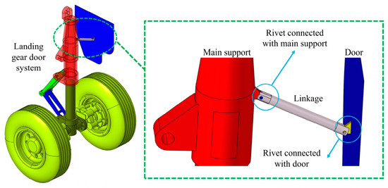
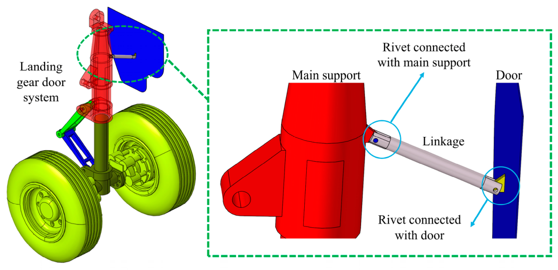
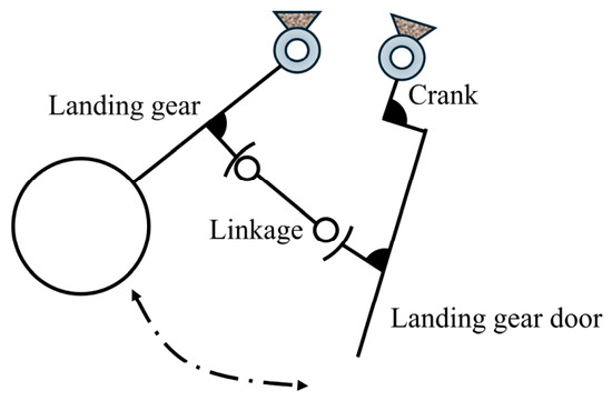
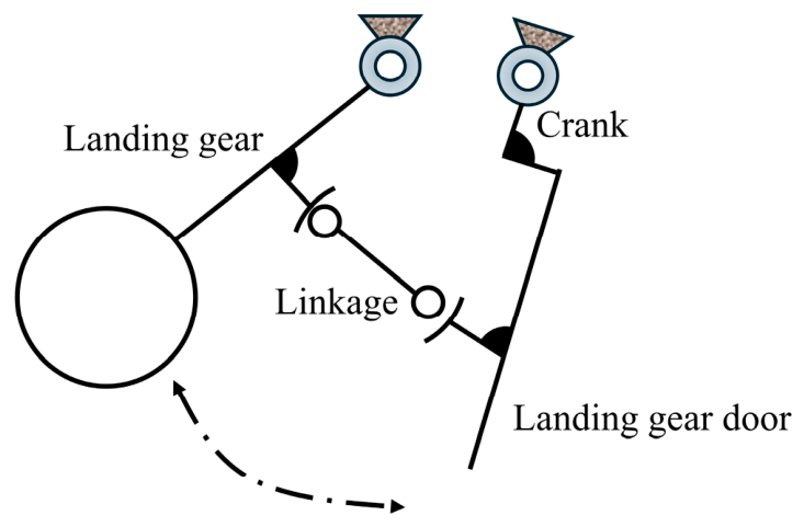
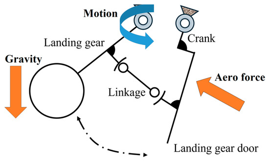
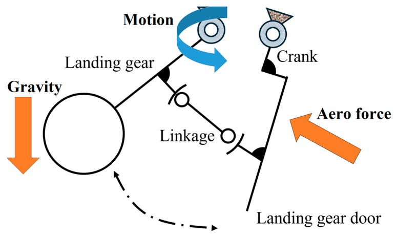
Figure 1 illustrates a representative door-coupled landing gear mechanism. The linkage system primarily consists of the main support, connecting linkage, follower door, strut pin joint, and door pin joint. During landing gear extension and retraction, the main support drives the door to move synchronously through the connecting linkage, thereby enabling coordinated motion between the linkage mechanism and the landing gear door. A schematic illustration of the operating principle is presented in Figure 2. Notably, during multiple landing gear retraction and extension tests, significant structural deformation is observed in the local region of the connecting linkage near the strut pin joint. The transfer of excessive force and moment loads further increases the criticality of this region, making it highly susceptible to failure. Therefore, verification and analysis should focus particularly on the strength and stiffness margins of the connecting linkage to ensure reliable operation of the door-coupled landing gear mechanism during service.
Figure 1.
Schematic of a representative door-coupled landing gear mechanism.
Figure 2.
Operating principle of the representative door-coupled landing gear mechanism.
3. Finite Element Modeling and Validation of Flexible Components
To accurately evaluate the flexible response of the connecting linkage and provide both quantitative and qualitative guidance for iterative design of the door-coupled mechanism, this section employed a flexible multibody dynamic approach based on nonlinear finite element theory to model the critical linkage component prone to recurrent failures. A series of numerical case studies were then conducted to validate the accuracy and applicability of the proposed modeling methodology.
3.1. Modeling
3.1.1. Kinematic Description
This study adopted the displacement interpolation framework commonly used in conventional finite element methods, in which the displacement vector of an arbitrary material point within an element is represented as a polynomial interpolation function of the nodal displacements. No modal reduction approximations are applied, and all nodal degrees of freedom are fully retained. For an n-node element, the displacement vector u of an arbitrary point within the element is interpolated using the shape functions as follows:
where N denotes the shape function matrix of the element, and q represents the generalized coordinate vector of the element. Accordingly, the velocity field and acceleration field of an arbitrary material point within the element are obtained by taking the time derivatives of Equation (1):
In general, the shape function components of a standard eight-node hexahedral solid element are expressed as follows:
where ξ, η, and ζ are three dimensionless normalized coordinates, which play a crucial role in the formulation and application of isoparametric elements.
3.1.2. Constitutive Equation
The representative door-coupled landing gear mechanism investigated in this study was primarily fabricated from high-strength metallic materials, including ultra-high-strength steel 300M and high-strength aluminum alloy 7075-T6. To characterize the mechanical behavior of the connecting linkage, an elastoplastic constitutive equation accounting for plastic yielding was employed. During the elastic deformation stage, the stress–strain relationship strictly follows Hooke’s law, described as follows:
where σ and ε denote the stress tensor and strain tensor, respectively, while D represents the elastic stiffness matrix, which is expressed as follows:
where λ and μ denote the first and second Lamé constants, respectively, whose relationships with Young’s modulus E and Poisson’s ratio ν are calculated as follows:
Plastic deformation was analyzed using the von Mises plasticity model based on J2 flow theory, which is well suited for metallic materials under low strain-rate conditions. The yield function is expressed as follows:
where s denotes the deviatoric stress tensor, Y represents the yield stress, and β is the back stress tensor used to characterize kinematic hardening. In determining the material state, if f < 0, the material remains in the elastic regime; if f = 0, the material enters the plastic regime; whereas the condition f > 0 is physically inadmissible. It should be noted that, when the material is in the plastic state and the deviatoric strain rate is nonzero, plastic flow occurs. The associated flow rule is defined as follows:
In addition to the yield criterion and flow rule described above, two further aspects of the material model warrant clarification. First, with regard to the hardening behavior, the von Mises plasticity model employed in this study adopts an isotropic hardening rule, in which the yield surface expands uniformly with increasing equivalent plastic strain while maintaining a fixed center in stress space. The evolution of the yield stress Y in Equation (7) is determined as a function of the equivalent plastic strain using a piecewise-linear hardening law. Although the back stress tensor β is retained in the general formulation of Equation (7) for completeness, it is not activated in the present simulations, as the loading conditions do not involve cyclic loading with plastic strain reversal that would necessitate a kinematic hardening description. Second, to represent additional energy dissipation in the flexible linkage during dynamic response, Rayleigh damping is incorporated into the time-domain integration of the equations of motion. The Rayleigh damping coefficients are calibrated such that the damping ratios of the first two vibrational modes of the flexible linkage match those obtained from the ABAQUS reference solutions, ensuring consistent dissipation characteristics between the present model and the reference solution.
3.1.3. Dynamic Equation
Based on the principle of virtual work, the differential–algebraic equations of motion for the landing gear–door system, incorporating constraint equations and Lagrange multipliers, are formulated as follows:
where M denotes the system mass matrix, fint represents the elastoplastic force vector, and fext is the external force vector. Φ denotes the constraint equations of the system, while Λ represents the Lagrange multiplier vector. Figure 3 presents the finite element discretization mesh of the key structural components, including the flexible linkage and pin joints.
Figure 3.
Finite element mesh discretization of key flexible components.
Before presenting the dynamic results, it is important to clarify the overall analysis workflow and the mechanism of load transmission from the global assembly to the local component. The simulation was performed using a fully integrated rigid–flexible coupled multibody dynamic framework, in which the flexible connecting linkage was embedded directly into the global mechanism model through kinematic constraints imposed at the hinge joints. Under this unified formulation, the global and local responses were solved simultaneously at each time step rather than through a sequential or loosely coupled procedure. As the main support followed the prescribed driving motion, the resulting joint reaction forces were directly transmitted to the flexible linkage through the constraints at the strut pin and door pin joints, thereby transferring global inertial and aerodynamic loads to the local component without requiring separate load extraction or manual load mapping. The stress and strain fields within the flexible linkage were extracted directly from the converged solution of the coupled system. This integrated approach ensures that force equilibrium and displacement compatibility between the flexible linkage and surrounding rigid bodies are consistently satisfied throughout the deployment process.
3.2. Validation
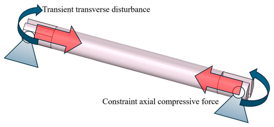
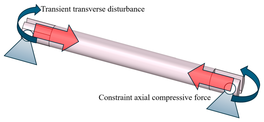
To preliminarily validate the accuracy and effectiveness of the flexible linkage rod dynamic model developed using the finite element method, a pin-jointed linkage rod subjected to combined axial compression and transverse disturbance was designed. The numerical results obtained from this model were compared in detail with the highly reliable reference solution provided by ABAQUS to ensure credibility. Figure 4 illustrates the pin-jointed linkage rod subjected to combined axial compression and transverse disturbance, and Table 1 presents the basic physical parameters of the rod.
Figure 4.
Simply supported flexible linkage rod subjected to a central transient load.
Table 1.
Basic physical parameters of the flexible linkage rod.
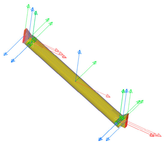
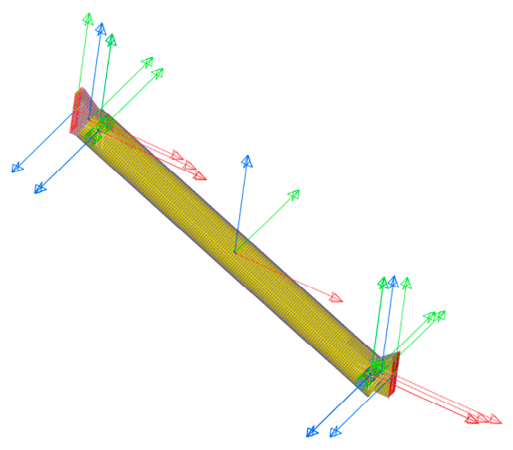
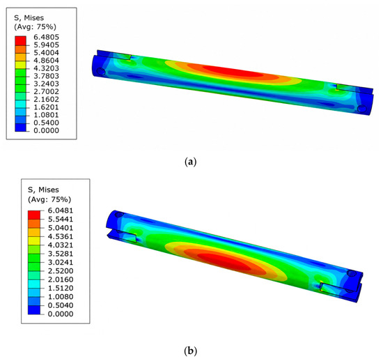
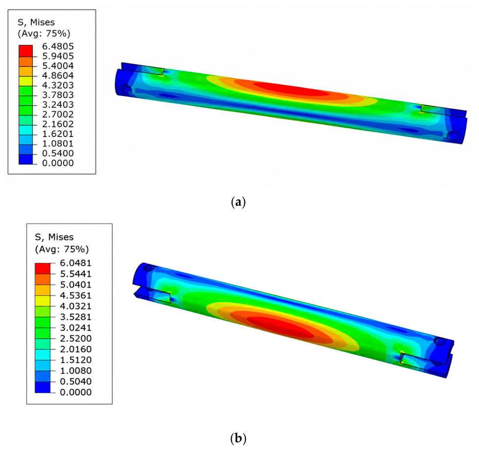
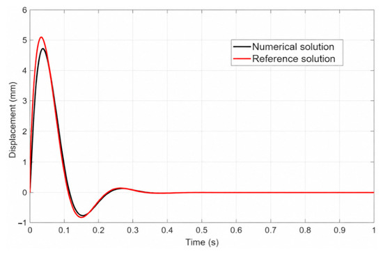
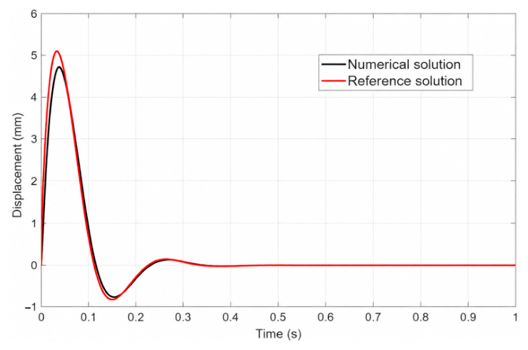
As shown in Figure 4, The rod was pin-supported at both ends, with a constant axial compressive force of 1000 N applied to simulate the in situ axial load of the connecting linkage and a transient transverse disturbance of 1000 N·m applied at the end to induce bending effects. The load duration was set to 0.5 s. Figure 5 presents a stress contour plot at a characteristic time of 0.5 s, comparing the reference solution with the numerical results obtained in this study. Figure 6 compares the vertical displacement at the center of the rod. Notably, the absolute stress magnitude in this validation benchmark depends on the applied test load and is not representative of actual service loads; the critical metric is the relative error with respect to the ABAQUS reference solution. The stress contour comparison indicates that, under this coupled axial-bending loading condition, the computed stress distribution agrees closely with the reference solution, with the maximum stress (on the order of 6.48 MPa) from the present model exhibiting a relative error of less than 2%. These results demonstrate good numerical accuracy and consistency. Notably, the center-point vertical displacement from this model also agrees well with the reference solution. The similar vibration evolution patterns confirm the reliability of the modeling approach, demonstrating its suitability for further analysis of multibody system dynamic responses.
Figure 5.
Comparison of stress contours of the flexible linkage rod at 0.5 s: (a) Stress contour of the flexible linkage rod from ABAQUS reference solution; (b) stress contour of the flexible linkage rod from the present numerical model.
Figure 6.
Comparison of vertical displacement at the rod center.
It should be noted that the above validation primarily assessed the numerical accuracy of the flexible component solver and the elastoplastic constitutive implementation, rather than that of the complete multibody system involving joints, constraints, and prescribed motions. A comprehensive system-level validation would ideally require comparison with experimental measurements or high-fidelity commercial software results for the complete mechanism, which will be pursued in our future work. Nevertheless, the present validation is sufficient to demonstrate the accuracy of the flexible link dynamics, which represents the key novel aspect of our rigid–flexible coupling formulation. The constraint enforcement and joint kinematics follow standard multibody dynamics procedures that have been extensively validated in the literature [10,11,12,14,15], and the current validation demonstrates that the flexible response of the critical linkage under external loading is accurately captured.
4. Dynamic Response Analysis
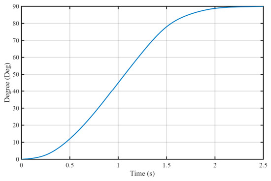
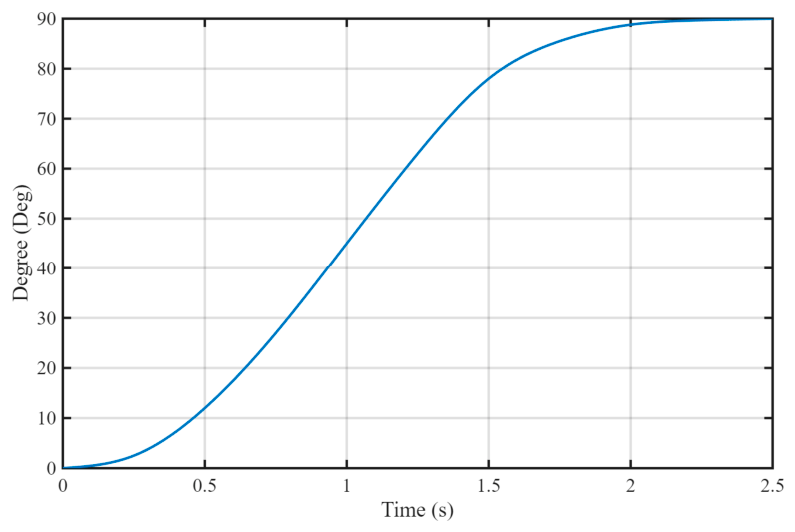
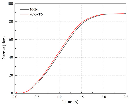
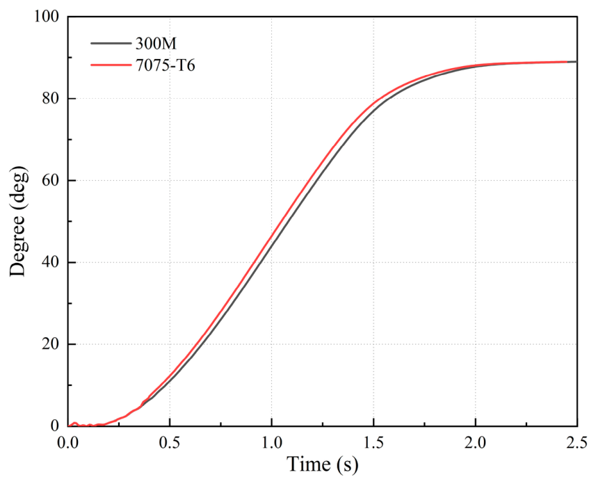
This section investigates the effect of material selection on the deployment of the cabin door linkage landing gear, aiming to clarify how different materials influence the flexible response of the mechanism and to provide guidance for the safe maintenance of the frequently failing left-end joint. The analysis focused on key indicators, including stress in critical flexible linkage rods, the response trajectory of the cabin door, and its velocity characteristics. The prescribed angle variation in the landing gear drive is shown in Figure 7. The motion process spans 2.5 s, until the main support is fully deployed.
Figure 7.
Prescribed angle variation in the landing gear main drive.
Prior to presenting the dynamic results, it is essential to clarify the load transfer mechanism from the global assembly to the local flexible component, as this mechanism underpins the interpretation of the stress distributions presented subsequently. As illustrated in Figure 1, the kinematic chain of the door-coupled landing gear system comprised the main support, connecting linkage, and follower door. The drive torque applied to the main support generated a constraint force at the strut pin joint, which was transmitted through the connecting linkage to the door pin joint, ultimately driving the follower door against the aerodynamic resistance acting on its surface. At the strut pin joint, the resultant hinge force was decomposed into an axial component along the longitudinal axis of the connecting linkage and a transverse component perpendicular to it. The axial component governed the primary tensile or compressive stress state within the linkage, whereas the transverse component, combined with the eccentricity between the hinge center and the neutral axis of the linkage cross-section, induced significant bending moments. This combined axial-bending loading condition made the hinge-adjacent regions particularly susceptible to stress concentrations, which is consistent with the numerical results presented below, where the maximum stresses consistently localized at the joint areas regardless of material selection. This load transfer pathway also explains why the left linkage, situated at the critical interface between the main support and the connecting rod, frequently experiences structural deformation and fatigue failures in engineering applications. The loading and boundary conditions applied to the assembly are shown in Figure 8.
Figure 8.
The loading and boundary conditions applied to the assembly.
To investigate the effect of material selection, several numerical simulation scenarios were designed. The material candidates for the cabin door linkage landing gear mechanism include 300M and 7075-T6. Table 2 summarizes the mechanical properties of these materials. While 300M provides higher structural stiffness and yield strength, 7075-T6 offers a distinct advantage in lightweight design.
Table 2.
Mechanical properties of 300M and 7075-T6.
Additionally, during deployment and retraction of the cabin door linkage landing gear, the cabin door was also subjected to significant aerodynamic loads, which affected the motion of the mechanism. Table 3 presents the aerodynamic simulation parameters under standard operating conditions. The aerodynamic load acting on the cabin door was simplified as a concentrated force applied at the aerodynamic center of the door surface, with its magnitude calculated as follows:
where denotes the air density, represents the drag coefficient, A is the frontal area of the cabin door, and v is the airspeed. The corresponding parameter values are summarized in Table 3. The aerodynamic force was assumed to act normal to the door surface, and its magnitude was maintained constant throughout the door deployment process, as the airspeed variation during the short retraction–extension cycle (2.5 s) was negligible for the present analysis. This simplified representation was adopted because the primary objective of this study is to compare the relative effects of different material selections on the dynamic response, rather than to achieve highly accurate absolute predictions of the aerodynamic loading.
Table 3.
Aerodynamic parameters under standard conditions.
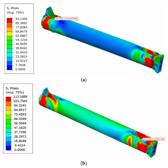
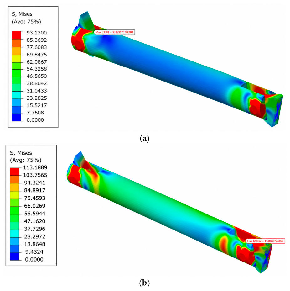
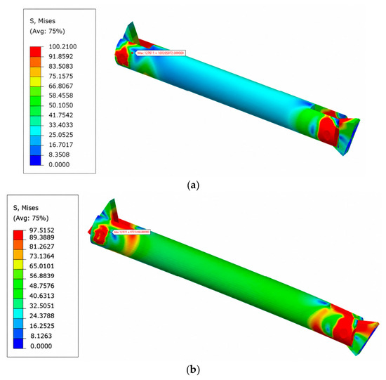
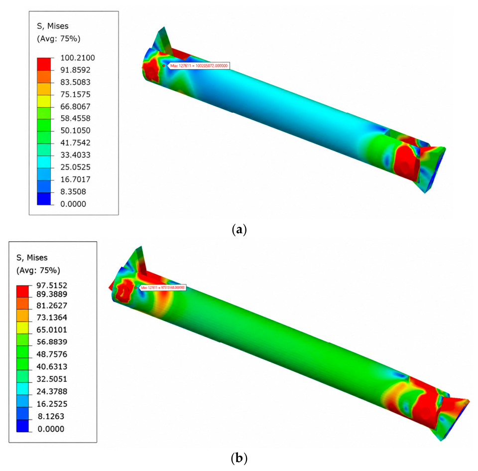
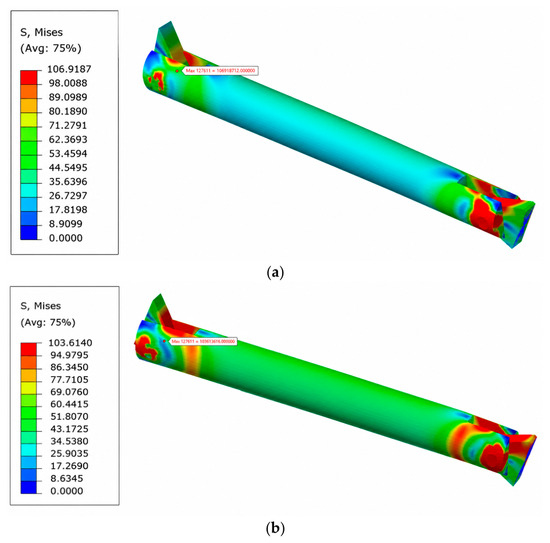
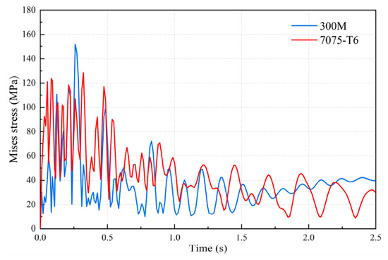
Figure 9, Figure 10 and Figure 11 present the stress contours of the key linkage mechanisms at 0.5 s, 1 s, and 2 s, respectively, for the two material selections: 300M and 7075-T6. Figure 12 shows the time history of the maximum stress for both materials. In all configurations, the maximum stress consistently occurs at the left and right hinge joints, which are critical regions for structural strength and stiffness verification and therefore require particular attention. During the early stages of landing gear deployment, the stress in 7075-T6 exceeds that in 300M. However, the peak stress in 300M reaches approximately 168 MPa, about 8.4% higher than that of 7075-T6, indicating that higher structural stiffness leads to larger stress peaks in the flexible rods. Notably, the maximum stress in 7075-T6 exhibits lower oscillation frequency, an advantage particularly evident during the middle and later stages of landing gear deployment. It is important to clarify that the observed attenuation of stress oscillations does not originate from intrinsic material damping, because the employed elastoplastic constitutive model does not incorporate rate-dependent or viscoelastic dissipation mechanisms. Instead, the oscillation frequency is primarily governed by the structural stiffness of the linkage, which is directly determined by the material Young’s modulus. The lower stress oscillation frequency observed for 7075-T6 arises from its lower elastic modulus (71 GPa) compared with that of 300M (210 GPa), which reduces the structural stiffness and consequently lowered the natural frequency of the flexible linkage. The gradual decay of oscillation amplitude observed in both cases is mainly attributed to the numerical dissipation inherent in the time integration scheme (the Newmark-β method) and, to a lesser extent, by energy dissipation associated with localized plastic deformation. Therefore, the advantage of 7075-T6 in terms of vibration response should be understood as a consequence of its lower structural stiffness rather than superior intrinsic damping capacity. This stiffness characteristic may be advantageous for suppressing high-frequency vibrations in lightweight structural applications.
Figure 9.
Stress contour of the key linkage mechanism at 0.5 s: (a) 300M; (b) 7075-T6.
Figure 10.
Stress contour of the key linkage mechanism at 1 s: (a) 300M; (b) 7075-T6.
Figure 11.
Stress contour of the key linkage mechanism at 2.5 s: (a) 300M; (b) 7075-T6.
Figure 12.
Time history of the maximum stress in the key linkage mechanism.
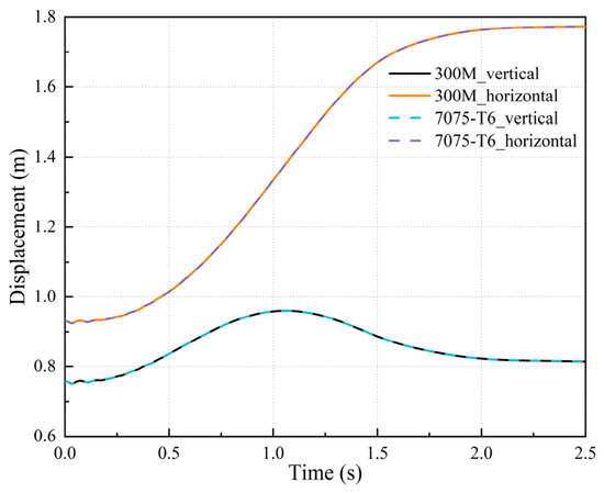
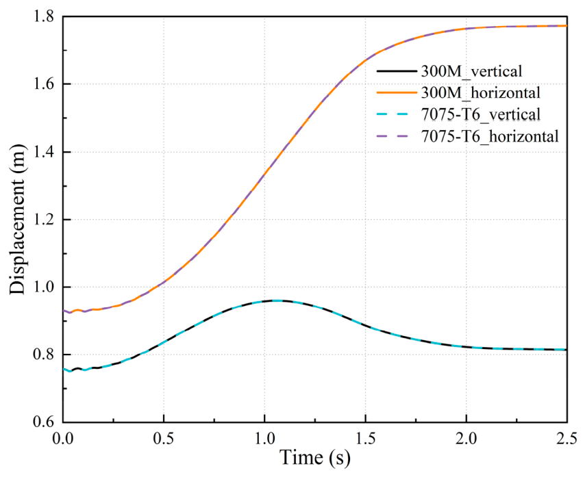
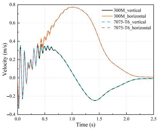
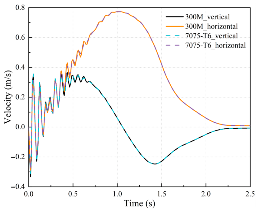
Figure 13 and Figure 14 show the vertical and horizontal displacement and velocity responses of the cabin door centroid under the action of the main drive. Figure 15 presents the rotation angle of the cabin door about its hinge axis. The results indicate that material selection has negligible effects on the motion responses, including displacement and velocity. The responses exhibit a high degree of agreement and consistency, suggesting that these parameters are not highly sensitive to the choice of engineering material. Therefore, related requirements and standards can be appropriately relaxed.
Figure 13.
Vertical and horizontal displacement of the cabin door centroid.
Figure 14.
Vertical and horizontal velocity of the cabin door centroid.
Figure 15.
Follow-up opening angle of the cabin door.
Quantitative comparison reveals that the maximum vertical displacement difference between the two material configurations is less than 0.05 mm (relative deviation < 0.15%), while the maximum horizontal displacement difference is less than 0.03 mm (relative deviation < 0.08%). Similarly, the maximum deviation in the cabin door opening angle is less than 0.02° (relative deviation < 0.05%). These results demonstrate that the kinematic responses are largely insensitive to material selection, with all relative deviations remaining below 0.2% of the corresponding motion amplitudes. Therefore, material selection has negligible effects on the motion responses, including displacement and velocity, and the responses obtained for the different materials exhibits close agreement.
To establish a clear relationship between the local stress behavior and the global deployment process, the deployment process is divided into three characteristic phases based on the main support angular position (Figure 8): Phase I (0–1.0 s, initial acceleration), Phase II (1.0–1.8 s, high-speed deployment with peak aerodynamic load), and Phase III (1.8–2.5 s, final locking and deceleration). As shown in Figure 12, the peak stress in both material configurations occurs during Phase II, which coincides with the maximum aerodynamic load on the cabin door (cf. Table 3). This indicates that aerodynamic resistance is the dominant external contributor to the stress peaks in the connecting linkage. Furthermore, the stress oscillations in 7075-T6 exhibit a markedly lower frequency than those in 300M throughout Phase III, corresponding to the final locking stage where residual vibrations are most pronounced. This correlation demonstrates that material selection, through its influence on elastic wave propagation speed and structural stiffness, directly affects the high-frequency vibration characteristics during the critical locking phase.
To quantitatively assess the influence of flexible deformation on global kinematics, an additional comparative simulation was performed using a fully rigid-body model (i.e., treating all components as rigid). The results show that the maximum deviation in cabin door opening angle between the rigid-body model and the rigid–flexible model is less than 0.5°, indicating that the kinematic responses (displacement, velocity, and opening angle) were only weakly affected by the elastic deformation of the connecting linkage for the present configuration. This finding justifies the adoption of the rigid–flexible coupling approach, not to improve kinematic predictions, but to enable accurate stress and fatigue evaluation of the critical linkage, which cannot be evaluated within a rigid-body framework.
5. Conclusions
The cabin door linkage landing gear mechanism was examined in this study, with particular attention given to structural deformation and jamming issues in key linkages during deployment and retraction. A nonlinear finite element based on rigid–flexible coupled dynamic model was developed. By treating the frequently failing left linkage as flexible, while keeping other components rigid, and incorporating elastoplastic constitutive relations along with Lagrange constraint equations, the model accurately captured the interaction between the flexible response of the linkage and the overall mechanism motion. Using this model, the dynamic behavior of the landing gear during deployment was systematically compared for two material options: steel 300M and Al 7075-T6. The main conclusions are summarized as follows:
- (1)
- The simply supported beam central impact example demonstrated that the peak stress computed by the present model deviates by less than 2% from the reference solution. The displacement response also shows excellent agreement, confirming the accuracy and reliability of the modeling approach.
- (2)
- Regardless of material selection, the maximum stress consistently occurs at the hinge joints, which are critical for structural strength verification. The peak stress in 300M reaches approximately 168 MPa, about 8.4% higher than that in 7075-T6, indicating that higher structural stiffness leads to larger stress peaks in flexible rods; 7075-T6 exhibits lower stress oscillation frequency and superior elastic vibration damping, which helps suppress high-frequency vibrations. This property is particularly valuable for lightweight aircraft or for non-primary load-bearing components. However, the above comparison was confined to the elastic response and vibration characteristics of the linkage under the specified loading conditions. A comprehensive material selection for engineering applications would require further consideration of fatigue life, manufacturing cost, corrosion resistance, and strength-to-weight ratio, which are beyond the scope of the present study. The results presented herein are intended to provide insights into the dynamic response characteristics of the two candidate materials, rather than to recommend a universal material choice for all applications.
- (3)
- Material selection has negligible influence on the motion responses of the cabin door centroid, including displacement, velocity, and opening angle, with trajectories showing a high degree of agreement. This indicates that kinematic parameters are insensitive to variations in material elastic modulus. Therefore, provided strength requirements are met; aluminum alloy can be prioritized to reduce peak stresses and improve vibration damping, while constraints on motion responses may be appropriately relaxed.
Author Contributions
F.L., conceptualization, methodology, investigation, writing—original draft preparation, writing—review and editing; M.Z., validation, investigation; writing—review and editing; Y.L., writing—review and editing; J.T., writing—review and editing; M.T., conceptualization, project administration. All authors have read and agreed to the published version of the manuscript.
Funding
This research received no external funding.
Data Availability Statement
Data are contained within the article.
Conflicts of Interest
The authors declare no conflicts of interest.
References
- Gao, S.; Fan, S.; Wang, W. The dynamic behavior and nonlinear characteristics of aircraft landing gear retraction mechanism considering atmospheric corrosion. Appl. Math. Model. 2024, 135, 438–456. [Google Scholar] [CrossRef] [Scilit]
- Nie, H.; Wei, X. Key technologies of landing gear for large civil aircraft. J. Nanjing Univ. Aeronaut. Astronaut. 2008, 40, 427–432. [Google Scholar]
- Reveley, M.S.; Briggs, J.L.; Evans, J.K.; Jones, S.M.; Kurtoglu, T.; Leone, K.M.; Sandifer, C.E. Causal factors and adverse events of aviation accidents and incidents related to integrated vehicle health management. In Aviation Safety Reporting System; National Aeronautics and Space Administration: Cleveland, OH, USA, 2011. [Google Scholar]
- Xu, J. Design of Linkage Mechanism and Air Tightness Study for Aircraft Landing Gear Door. Master’s Thesis, Nanjing University of Aeronautics and Astronautics, Nanjing, China, 2017. [Google Scholar]
- Yang, G. Research on linkage mechanism of nose landing gear door. Sci. Technol. Vis. 2017, 14, 73+95. [Google Scholar]
- Yin, Y. Research on Retraction Dynamics and Reliability of Landing Gear. Ph.D. Thesis, Nanjing University of Aeronautics and Astronautics, Nanjing, China, 2017. [Google Scholar]
- Shi, X.; Zhang, J.; Liang, T.; Yin, Y.; Wei, X. Failure analysis and optimization design of landing gear door linkage mechanism. J. Nanjing Univ. Aeronaut. Astronaut. 2025, 57, 292–300. [Google Scholar]
- Knowles, J.A.C.; Krauskopf, B.; Lowenberg, M.H. Numerical continuation applied to landing gear mechanism analysis. J. Aircr. 2011, 48, 1254–1262. [Google Scholar] [CrossRef] [Scilit][Green Version]
- Knowles, J.A.C.; Krauskopf, B.; Lowenberg, M.H.; Neild, S.A.; Thota, P. Numerical continuation analysis of a dual-sidestay main landing gear mechanism. J. Aircr. 2014, 51, 129–143. [Google Scholar] [CrossRef] [Scilit][Green Version]
- Flores, P.; Ambrósio, J. Revolute joints with clearance in multibody systems. Comput. Struct. 2004, 82, 1359–1369. [Google Scholar] [CrossRef] [Scilit]
- Flores, P.; Koshy, C.S.; Lankarani, H.M.; Ambrósio, J.; Claro, J.C.P. Numerical and experimental investigation on multibody systems with revolute clearance joints. Nonlinear Dyn. 2011, 65, 383–398. [Google Scholar] [CrossRef] [Scilit]
- Flores, P.; Machado, M.; Seabra, E.A.R.; Silva, M.T. A parametric study on the Baumgarte stabilization method for forward dynamics of constrained multibody systems. J. Comput. Nonlinear Dyn. 2009, 6, 011019. [Google Scholar] [CrossRef] [Scilit]
- Zhu, Z. Reliability Analysis of Retraction and Energy Absorption Characteristics of Aircraft Landing Gear System. Ph.D. Thesis, Northwestern Polytechnical University, Xi’an, China, 2020. [Google Scholar]
- Zhang, Z.; Wu, S.; Zhu, H.; Nie, H.; Wei, X. Analysis of the synchronized locking dynamic characteristics of a dual-sidestay main landing gear retraction mechanism. Aerospace 2024, 11, 356. [Google Scholar] [CrossRef] [Scilit]
- Gao, S.; Fan, S.; Fan, S. Dynamic characteristics of aircraft landing gear retraction mechanism under the coupling effects of extreme conditions. Acta Mech. Sin. 2025, 41, 524105. [Google Scholar] [CrossRef] [Scilit]
- Erkaya, S.; Uzmay, B. Investigation on effect of joint clearance on dynamics of four-bar mechanism. Nonlinear Dyn. 2009, 58, 179–198. [Google Scholar] [CrossRef] [Scilit]
- Erkaya, S.; Dogan, S. A comparative analysis of joint clearance effects on articulated and partly compliant mechanisms. Nonlinear Dyn. 2015, 81, 323–341. [Google Scholar] [CrossRef] [Scilit]
- Xiao, L.; Yan, F.; Chen, T.; Zhang, S.; Jiang, S. Study on nonlinear dynamics of rigid-flexible coupling multi-link mechanism considering various kinds of clearances. Nonlinear Dyn. 2023, 111, 3279–3301. [Google Scholar] [CrossRef] [Scilit]
- Ossa, E.A. Failure analysis of a civil aircraft landing gear. Eng. Fail. Anal. 2006, 13, 1177–1183. [Google Scholar] [CrossRef] [Scilit]
- Zhang, J.; Liu, Y.; Su, D. Reliability analysis technology and application of aircraft mechanisms. Acta Aeronaut. Astronaut. Sin. 2006, 27, 827–829. [Google Scholar]
- Chinvorarat, S.; Vallikul, P. A novel retractable landing gear of a light amphibious airplane: Design, synthesis, analysis, and implementation. Aircr. Eng. Aerosp. Technol. 2021, 93, 1547–1558. [Google Scholar] [CrossRef] [Scilit]
- Xu, K.; Yin, Y.; Yang, Y.; Nie, H.; Wei, X. Bifurcation analysis of dual-sidestay landing gear locking performance considering joint clearance. Chin. J. Aeronaut. 2022, 35, 209–226. [Google Scholar] [CrossRef] [Scilit]
- Knowles, J.A.C.; Krauskopf, B.; Lowenberg, M. Numerical continuation analysis of a three-dimensional aircraft main landing gear mechanism. Nonlinear Dyn. 2013, 71, 331–352. [Google Scholar] [CrossRef] [Scilit][Green Version]
- Tartaruga, I.; Cooper, J.; Lowenberg, M.; Lemmens, Y. Enhanced evolutionary-based optimization techniques applied to a nonlinear landing gear design problem. J. Aircr. 2019, 56, 2004–2018. [Google Scholar] [CrossRef] [Scilit]
- Yuan, C.; Cui, H. Force/torque control for aerodynamic load simulator of an undercarriage. Chin. Hydraul. Pneum. 2004, 3, 23–26. [Google Scholar]

Disclaimer/Publisher’s Note: The statements, opinions and data contained in all publications are solely those of the individual author(s) and contributor(s) and not of MDPI and/or the editor(s). MDPI and/or the editor(s) disclaim responsibility for any injury to people or property resulting from any ideas, methods, instructions or products referred to in the content. |
© 2026 by the authors. Licensee MDPI, Basel, Switzerland. This article is an open access article distributed under the terms and conditions of the Creative Commons Attribution (CC BY) license.