


Abstract
Since the thrust of a single-emitter Field Emission Electric Propulsion (FEEP) thruster is limited to 1–20 µN, a multi-emitter configuration is necessary to increase the thrust capacity. This study proposes a hybrid multi-emitter configuration designed to achieve uniform current distribution, enhanced thrust, and high efficiency. The design consists of linearly arrayed hybrid emitters, dummy emitters, and a slit extractor. Preliminary experiments investigated Taylor cone formation and ion emission characteristics. Capillary emitters exhibited pulse, oscillating, and continuous emission modes depending on the power supply method, whereas hybrid emitters exhibited only continuous emission with well-confined Taylor cone formation and consistent current–voltage characteristics. Key design requirements for the hybrid multi-emitter configuration include axially aligned electric field distribution and a large extractor hole diameter. The proposed configuration generates the required electric field distribution with the aid of dummy emitters, achieving uniform current emission across the emitter array. The calculated maximum thrust and emitter power-to-thrust ratio were 279.0 µN and 160.4 mW/µN, respectively, at an emitter current of 2.86 mA. These results demonstrate the potential of the proposed hybrid multi-emitter configuration as a scalable emitter architecture for FEEP thruster applications requiring uniform ion emission and increased thrust capacity.
1. Introduction
With rapid advancements in the private aerospace sector, the significance of CubeSats is increasing due to their cost-effective manufacturing and deployment. CubeSats are satellites constructed in cube units, each characterized by dimensions of 10 cm × 10 cm × 10 cm and a mass of less than 1.33 kg (1 U) [1]. The economic advantages of CubeSats stem from their high packing density, made possible by their compact size. However, as mission requirements become increasingly complex, the volume and mass of CubeSats continue to decrease. This evolution has led to a growing demand for propulsion systems tailored to CubeSats. Due to the limited internal space, CubeSats require thrusters within the size range of 0.25–1 U and a wet mass of only a few kilograms [2]. Consequently, thrusters for CubeSats must exhibit high specific impulse, utilize high-density propellants, and operate efficiently within miniaturized geometries.
Field Emission Electric Propulsion (FEEP) is a propulsion technique that ionizes and accelerates liquid metal propellants through the formation of Taylor cones, which occur due to the strong electric fields applied to sharp emitter tips. FEEP thrusters are well-suited for CubeSat applications, utilizing high-density liquid metals as propellants, offering high specific impulse due to their electric propulsion mechanism, and operating more efficiently in small dimensions owing to the characteristics of field evaporation [3,4]. Nevertheless, the limited thrust capability of single-emitter FEEP thrusters, typically in the range of 1–20 µN, presents a significant obstacle to broader applications [5]. To overcome this limitation, emitter configurations offering multiple emission sites, such as blade emitters, slit emitters, and porous emitters, have been explored to enhance the thrust capacity of FEEP thrusters [6,7]. However, these configurations often suffer from current concentration at a few emission sites, particularly at the ends of slit and blade emitters, due to the absence of sharp solid structures where the Taylor cones are designated to form. Pfeffer et al. reported a linear array of solid nickel needles installed in a frame similar to a slit-type emitter, with a packing density of 150 needles/cm and a strip length of 3 cm, using cesium as the propellant [8]. They also employed a linear slit extractor with enlarged holes at both ends to tune the electric field distribution. This work demonstrated the feasibility of high-density needle arrays for liquid-metal ion emission. However, because the number and spatial distribution of the active emission sites were not directly observed, the emission uniformity and per-site characteristics required for FEEP multi-emitter design remain insufficiently clarified. In tests of a ring-type porous emitter, Tajmar et al. observed that the liquid-metal film was drawn toward a limited number of dominant emission sites rather than being uniformly distributed across the emitter [6]. These previous studies indicate that high-density FEEP multi-emitter design requires not only dense emitter arrangements but also controlled emission-site localization and emitter-to-emitter current uniformity.
To achieve uniform emission across FEEP emitters, research has focused on multi-emitter configurations with distinct emission sites separated by arrays of sharp emitters. For instance, a 3 × 3 grid-array of capillary emitters [6] and solid needle emitters [9] demonstrated stable current–voltage characteristics, with evaluated thrust ranges of 10–500 µN and 0.4–100 µN, and emitter activation rates of 100% and 77.8%, respectively. However, the emitter packing density in grid arrays is limited by the required spacing between emitters. Additionally, propellant contamination due to broad propellant exposure in needle emitters has hindered their performance in long-term activations. Tajmar investigated a micro-electro-mechanical systems (MEMS) based µFEEP concept for miniaturizing the Austrian Research Centers Seibersdorf (ARCS) indium FEEP thruster, including a 21 × 21 emitter array prototype on a 5 × 5 mm area [10]. Lenard et al. reported silicon-based MEMS In-FET development by Sandia National Laboratories (SNL), ARCS, and Jet Propulsion Laboratory (JPL). Their work included a 5 × 5 MEMS-based In-FET module with individually addressable emitter/extractor pairs on a 15 × 15 mm wafer and a proposed 10 × 10 cm module with approximately 160,000 emitters for high-power scaling [11]. These studies demonstrated the feasibility of MEMS-based FEEP clustering, while indicating that emitter-to-emitter uniformity, fabrication accuracy, and emitter–extractor alignment remain critical for uniform and scalable multi-emitter operation.
On the other hand, porous crown emitters, consisting of an annular array of 28 porous tungsten needles, exhibit high emitter packing densities and superior emission characteristics while offering propellant protection. These emitters have achieved a thrust range of 0–1.5 mN and an average emitter activation rate of 90% [12]. Porous crown emitters have also obtained substantial flight heritage through indium-based FEEP propulsion systems. As of 2024, more than 200 FEEP propulsion systems based on this technology had been launched and used in LEO and GEO for applications including orbit acquisition, formation control, precise orbit keeping, and conjunction avoidance [13]. Despite these advantages, fabricating porous needle emitters using micro powder injection molding (µPIM) remains technically demanding, as achieving the desired pore structure and mechanical integrity requires precise control over feedstock properties, mold design, debinding process, and sintering conditions [14,15]. This complexity motivates the development of a multi-emitter configuration based on a simpler emitter architecture. To reduce manufacturing difficulty while protecting the propellant from contamination, capillary and hybrid emitters are promising candidates for FEEP multi-emitter systems.
The hybrid emitter integrates a sharply etched needle core with a capillary outer shell, thereby protecting the propellant while preserving a highly localized emission site. Similar needle–capillary configurations have been explored in related electrospray and liquid metal ion source (LMIS) studies. For LMISs, Tajmar proposed a wire-squeezed capillary emitter in which an unsharpened tungsten wire was inserted into a capillary [10], which increased the electrical impedance from 2.55 MΩ to 10.94 MΩ at emitter currents below 300 µA. However, the inserted wire was not intended to form a sharp and protruding emission site but rather to increase the hydraulic resistance inside the capillary. For ionic-liquid electrospray thrusters, Wright et al. tested a hybrid emitter consisting of a stainless-steel capillary and a sharpened tungsten needle [16]. Using a pressurized flow rate control device, the emitter produced spray–ion dual-mode emission depending on the flow rate and voltage condition. These studies demonstrate the usefulness of needle–capillary-type geometries for controlling liquid supply and emission behavior. However, their implementation in gallium-fed FEEP multi-emitter configurations, where localized ion emission, high electrical impedance, emitter-to-emitter current uniformity, and extractor-induced electric field distribution must be considered together, remains insufficiently explored.
To address these challenges, this study proposes a novel hybrid multi-emitter configuration for FEEP systems that integrates a plane-symmetric linear emitter array, dummy emitters at both ends, and a slit extractor. This architectural design is engineered to achieve a high emitter packing density and uniform current distribution while maintaining a simplified structure. Gallium is utilized as the propellant to alleviate the thermal management burden owing to its low melting point. The effects of the emitter array and extractor geometry are systematically investigated through a combination of numerical simulations and experimental validations. Specifically, Taylor cone formation and ion emission experiments are conducted in a vacuum environment to compare the performance of conventional capillary emitters with the proposed hybrid design. By providing a continuous emission mode and high electrical impedance, this hybrid configuration serves as a viable building block for scalable FEEP multi-emitter arrays. Ultimately, the developed system achieves high electrical impedance, a wide thrust capability, and a reasonably low power-to-thrust ratio, demonstrating its profound potential for next-generation FEEP thruster applications.
2. Theoretical Background
2.1. Taylor Cone
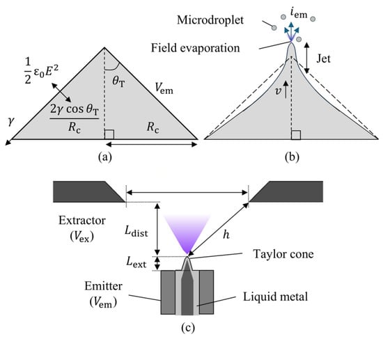
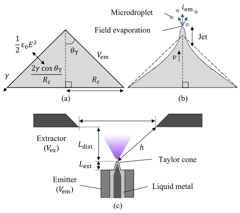
When a strong electric field is applied to the surface of a liquid droplet, a conical shape known as a Taylor cone is formed, as shown in Figure 1a,b. This occurs due to the balance between the Laplace pressure and the electric stress, described in Equation (1):
where represents the vacuum permittivity, is the electric field strength applied to the liquid surface, denotes the surface tension, is the Taylor cone half angle, and is the Taylor cone base radius. In the case of a liquid metal droplet, ionization occurs via field evaporation when the electric field strength at the apex of the Taylor cone exceeds 1010 V/m [17]. The onset voltage (), at which ion emission begins, can be calculated using Equation (2) for the needle emitters [18]:
where is the onset voltage of the needle emitter, is the geometric constant which is equal to 2 for a paraboloidal needle, and is the effective distance between the emitter and extractor electrode, which can be calculated using Equation (3):
where is the emitter–extractor vertical distance and is the extractor hole diameter, as shown in Figure 1c. For a multi-emitter configuration, in which the emitter position can deviate from the center of the extractor hole, represents the minimum distance between the emitter tip and the extractor rim.
Figure 1.
Schematics of ion emission and microdroplet formation on the liquid metal Taylor cone: (a) Taylor cone at onset; (b) Taylor cone with ion emission; (c) schematic of the emitter and extractor.
The applied voltage () is defined as the potential difference between the emitter voltage () and the extractor voltage () such that . When exceeds the onset voltage (), a Taylor cone forms at the emitter tip, ion emission starts, and the emitter current () is produced. For , the emitter current follows Equation (4) [19]:
where is the ion mass and is the elementary charge. By combining Equation (4) with Ohm’s law, expressed as , the electrical impedance () of the needle emitter can be derived as Equation (5):
At the onset of the Taylor cone formation, a conical shape having a half angle of 49.3° occurs as illustrated in Figure 1a [20]. When ion emission begins, a dynamic pressure term is added to Equation (1), resulting in Equation (6) [21]:
where is liquid metal density and is the flow velocity within the Taylor cone. The dynamic pressure deforms the Taylor cone into a concave shape, with a nanometer-scale cylindrical jet forming at the apex, as shown in Figure 1b. At low emitter currents, below 21.7–26.3 µA for gallium, the pure ionic mode emission dominates, with monatomic ions constituting the majority of the liquid metal mass consumption [20,22]. When the emitter current exceeds the critical threshold for pure ion emission, microdroplets are generated on the extruded jet due to Rayleigh instability [23]. At significantly higher emitter currents, pressure modulations caused by repeated jet formation and consumption induce Faraday instability, resulting in the formation of larger droplets at the apex of the Taylor cone [24,25,26].
2.2. Field Emission Electric Propulsion
Field emission electric propulsion (FEEP) is a propulsion method that utilizes ion emission from a Taylor cone as a thrust source. The generated thrust () can be calculated using Equation (7) [27]:
where is the ion beam divergence factor, is the extractor current, and is the electric charge of the ion. For the gallium propellant, and can be substituted with the atomic mass of gallium and the elementary charge (), respectively, since the composition of the field-evaporated ion beam is dominated by singly charged monatomic ions [17,22,28]. The ion beam divergence factor can be calculated using Equation (8) [29]:
where denotes the ion beam divergence half angle. For the NanoFEEP thruster, which employs gallium propellant, as a function of emitter current is given by Equation (9) [27]:
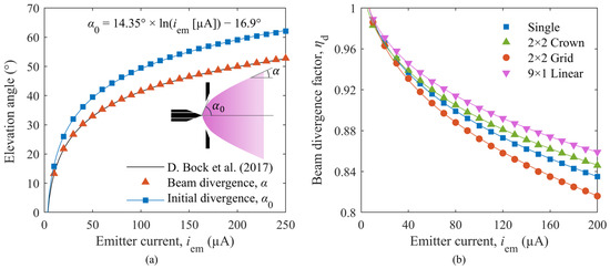
where is the emitter current expressed in microamperes (μA). Equation (9) was obtained for the specific emitter–extractor geometry of the NanoFEEP configuration and is therefore not directly applicable to other emitter–extractor geometries. In this study, it was used only as a reference relation for deriving the initial beam divergence half angle, , in the ion trajectory simulation.
For CubeSats, low thruster power consumption is essential due to their limited power availability. To evaluate thrust generation efficiency, the power-to-thrust ratio (PTR) is calculated using Equation (10):
3. Materials and Methods
3.1. Emitter Fabrication
3.1.1. Capillary Emitter
Capillary single-emitters are fabricated using stainless-steel capillaries with an inner diameter (I.D.) of 0.13 mm and an outer diameter (O.D.) of 0.30 mm, protruding 15 mm from the base. The tip of the capillary is electrochemically etched in a 10 M potassium hydroxide (KOH) solution using a direct current (DC) power supply. The etching process consists of two stages, applying 2.5 V potential for 900 s followed by 3 V potential for 300 s, with an immersion depth of 0.5 mm. After etching, the capillary is wetted with gallium using a 10% concentration hydrochloric acid (HCl) solution [30]. The wetting process involves sequentially supplying liquid gallium and HCl solution to the capillary while keeping its tip in contact with a gallium droplet immersed in HCl solution. After the wetting process, the capillary emitter was installed for the experiment with an emitter–extractor distance () of 0.2 mm and an extractor hole diameter () of 4 mm.
3.1.2. Hybrid Emitter
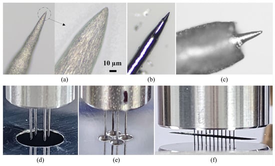
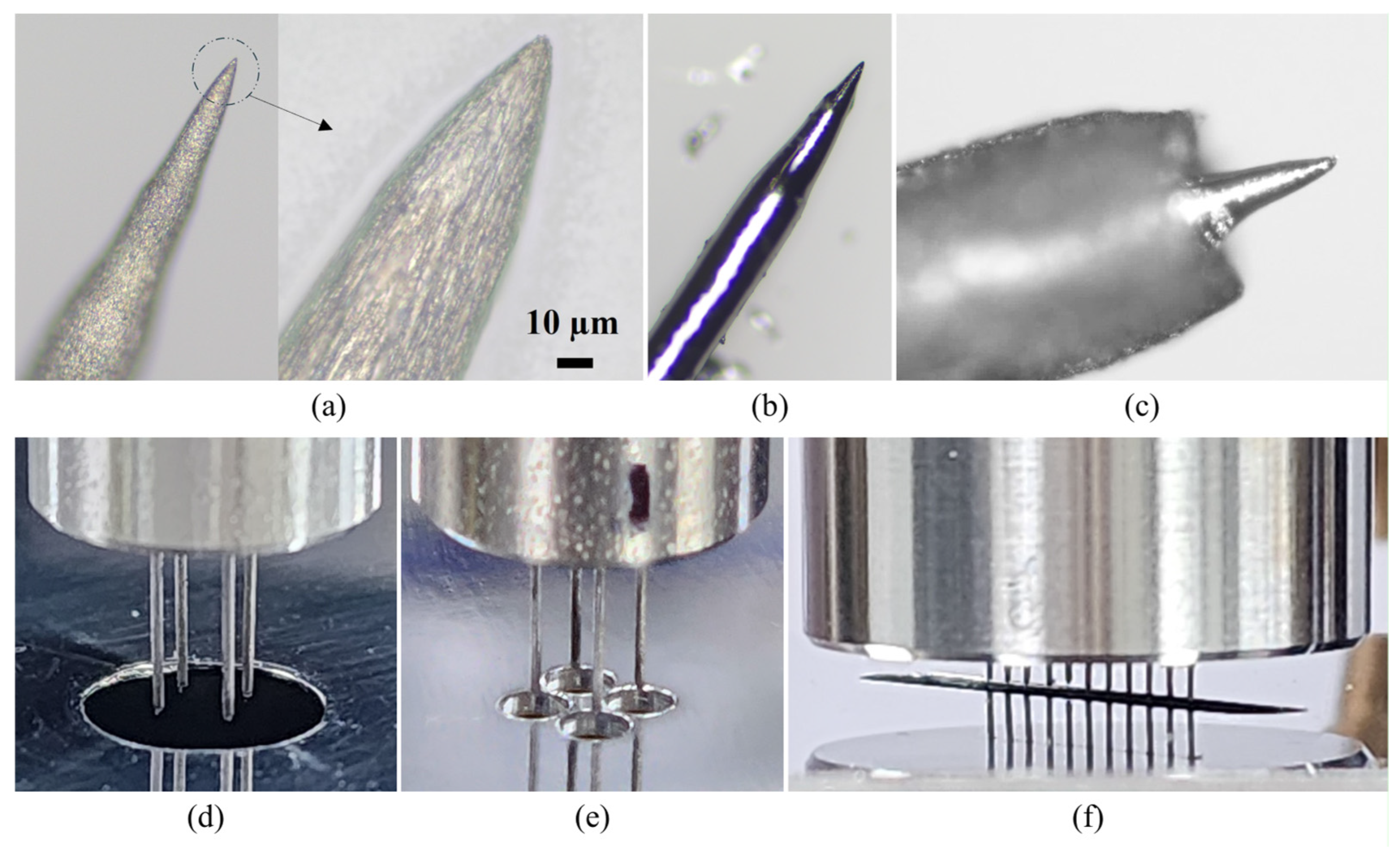
Hybrid emitters consisted of a gallium-wetted tungsten needle core enclosed within a tantalum capillary outer shell. The tungsten needle was fabricated by electrochemical etching of a tungsten wire with a diameter of 0.18 mm in a 10 M KOH solution using a DC power supply. First, etching was performed at 3 V for 50 s with an immersion depth of 15 mm to clean the wire surface and reduce the wire diameter to 0.15 mm. Second, 16.5 V was applied for 5 s at an immersion depth of 0.4 mm to sharpen the needle tip. Third, 3 V was applied for 5 s at an immersion depth of 0.1 mm to remove protruding residues and improve etching repeatability. Finally, 1.4 V was applied for 5 s at an immersion depth of 15 mm to create micro-grooves on the needle surface. Figure 2a shows the sharpened tungsten needle tip and the micro-grooves formed on its surface.
Figure 2.
Fabrication of the hybrid emitter and assembled multi-emitter configurations: (a) etched tungsten needle; (b) gallium-wetted tungsten needle; (c) needle inserted into the capillary; (d) crown-type array; (e) grid-type array; (f) linear array with slit extractor.
The etched tungsten needles were wetted with gallium under a vacuum of 1 × 10⁻³ Pa. During wetting, the alumina boat containing the gallium was heated to above 900 °C, as measured beneath the boat using a K-type thermocouple. The gallium film formed on the needle after the wetting process is shown in Figure 2b. After wetting, the needles were inserted from the bottom into tantalum capillaries with an O.D. of 0.31 mm and an I.D. of 0.16 mm. To improve emission uniformity, excess gallium was removed by suction to control the gallium meniscus at the emitter tip. Figure 2c shows the gallium meniscus after this control process.
For the hybrid single emitter, the tantalum capillary was fixed to a luer-lock base with a capillary protrusion length () of 5 mm. The tungsten needle was inserted with a needle extrusion length () of 0.17 mm. For the experiment, the emitter was positioned 0.8 mm above an extractor with 4 mm.
Hybrid multi-emitters consisted of a stainless-steel base, tantalum capillaries, and inserted tungsten needles. A 2 × 2 multi-emitter had a base height of 20 mm and an O.D. of 10 mm. The tantalum capillaries were fixed to the base using epoxy adhesive, with 6 mm. The distance between adjacent emitters was 2.12 mm. The corresponding extractors were fabricated from a 0.8 mm-thick 5052 aluminum alloy plate and designed in two configurations: a crown-type extractor with a 7 mm-diameter hole and a grid-type extractor with multiple 2 mm-diameter holes. The 5052 aluminum alloy was selected for the extractors because of its ease of machining for the laboratory-scale experiments. No visible deformation of the extractor was observed under the present ion emission test conditions; however, direct contact with leaked liquid gallium can degrade aluminum alloys. Therefore, gallium-compatible materials should be considered for practical thruster applications. Figure 2d and Figure 2e show the 2 × 2 multi-emitter aligned with the crown-type and grid-type extractors, respectively. For the crown-type extractor case, and were 0.12 mm and 0.50 mm, respectively. For the grid-type extractor case, and were 0.17 mm and 0.44 mm, respectively.
A 9 × 1 multi-emitter had a base height of 15 mm and an O.D. of 23 mm. To improve electric field uniformity and structural robustness, was reduced to 2 mm. The distance between adjacent emitters was 1.3 mm. The corresponding extractor had a round-ended slit with a length of 25 mm and a width of 4 mm. Figure 2f shows the fabricated 9 × 1 multi-emitter aligned with the slit extractor. For the experiment, and were 0.24 mm and 0.47 mm, respectively.
3.2. Ion Emission Test
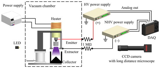
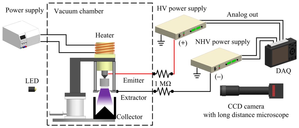
The Taylor cone formation and ion emission characteristics of capillary and hybrid emitters were evaluated through ion emission tests conducted in a vacuum environment (1 × 10⁻³ Pa). Figure 3 illustrates the experimental setup for the tests. The test models, including both single-emitters and multi-emitters, were attached to a stainless-steel syringe reservoir filled with liquid gallium. A high-voltage power supply (SHV600R, ConverTech, Gwangmyeong, Republic of Korea) applied a voltage ranging from 0 to 20 kV to the emitter. The specified load regulation and output-voltage ripple were 0.05% and less than 0.2% peak-to-peak, respectively. The reservoir was placed within an insulating poly-ether-ether-ketone (PEEK) block and surrounded by a heating wire connected to a power supply (BRP-5020, BRONN, Gunpo, Republic of Korea). Positioned in front of the emitter tip, the extractor electrode was connected to a negative high-voltage power supply (SHV120R, ConverTech, Gwangmyeong, Republic of Korea), applying −2 kV to repel secondary electrons to prevent interference. A 1 MΩ (±1%) spark-protection resistor was installed on each voltage input line of the emitter and extractor to reduce the risk of discharge during ion emission experiments, particularly when the liquid-metal meniscus was unstable. A graphite ion collector was placed beneath the extractor to minimize sputtering from surrounding components. Voltages (, ) and currents (, ) were recorded to a data acquisition (DAQ970A, Keysight Technologies, Santa Rosa, CA, USA) using an analog output signal from the high-voltage power supplies. The uncertainties of the voltage and current measurements are summarized in Table 1. Luminous emission from the emitter was identified using long-exposure images captured with a digital camera, whereas shadowgraphy was used to observe the Taylor cone shape and to determine whether the luminous emission originated from the needle tip or the needle shaft. The shadowgraphy setup consisted of a charge-coupled device (CCD) camera (BFS-U3-31S4M-C, Teledyne FLIR, Wilsonville, OR, USA), a long-distance microscope (12X Zoom, Navitar, Rochester, NY, USA), and an LED light source with a collimating lens. The light source was installed on the opposite side of the vacuum chamber and aligned with the emitter tip and CCD camera through the viewports.
Figure 3.
Schematic of experimental setup for ion emission test.
Table 1.
Measurement uncertainties of voltage and current instruments.
3.3. Numerical Simulation
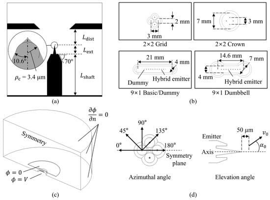
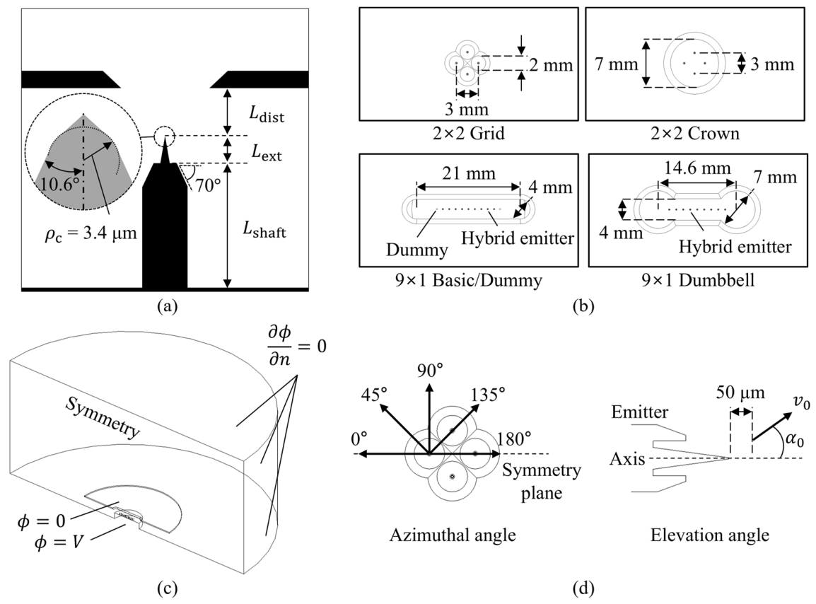
Numerical simulations were conducted using the commercial software Ansys Fluent 2023 R2 with user-defined functions (UDFs) to analyze the effects of the emitter and extractor geometries on the onset voltage and ion beam divergence. The domain geometry, grid generation, boundary conditions, and governing equations for electrostatics followed the methodology of Shin et al. [31]. Figure 4 shows the emitter, extractor, and computational domain geometries, along with the boundary conditions. Because the electrostatic simulation aimed to identify the onset voltage at which ion emission starts, space charge effects were neglected and the electric potential () was solved using the Laplace equation, as given by Equation (11):
Figure 4.
Computational setup for electrostatic and ion trajectory simulations: (a) emitter geometry and extractor position; (b) extractor geometries for different multi-emitter array types; (c) simulation domain and boundary conditions; (d) initial emission directions and positions of ions.
The electric field () was computed using Equation (12):
The onset voltage was determined by comparing the area-integrated axial electric stress on the Taylor cone surface with the surface tension force acting along the Taylor cone base, as expressed in Equation (13):
where denotes the axial component of the surface electric field and is the infinitesimal surface area on the Taylor cone. After determining the onset voltage, the emitter current was calculated using Ohm’s law given as Equation (14):
For the ion beam divergence simulation, the discrete particle model (DPM) was used. Following Vasiljevich and Tajmar [32], ions were released from a plane located 50 µm downstream of the needle apex. The initial divergence half-angle, , was defined as the angle between the emitter axis and the trajectory of the outermost ions included in the thrust calculation. The ions were initialized at the intersections of the 50 µm release plane with straight lines originating from the needle apex at an elevation angle of , with their initial velocity vectors aligned along these lines. Multiple ions were distributed in the azimuthal direction to account for the three-dimensional variation in the electric field. Thus, represents the effective angular extent of the ion beam after the near-source acceleration and space-charge effects occurring within 50 µm of the emission site have been incorporated. Although may also depend on source-specific conditions, the influence of moderate differences in the underlying emitter geometry was assumed to be secondary when a geometrically similar, axis-aligned single Taylor cone was maintained. The final beam divergence half-angle, , was determined from the elevation angles of the ions initialized at , evaluated 90 mm downstream of the emitter after they had passed through the extractor aperture, where their trajectories had approached their asymptotic directions. Five azimuthal directions were simulated, as shown in Figure 4d: two opposite directions parallel to the symmetry planes and three intermediate directions at 45° intervals. Considering symmetry, these five simulated directions corresponded to eight effective azimuthal directions.
The initial ion velocity, , was calculated from energy conservation using Equation (15):
where denotes the electric potential at the initial ion position . The body force applied to each ion due to the Coulomb force was defined using Equation (16):
where is the body force per unit ion mass and denotes the local electric field at the ion position. During the trajectory calculation, the velocity magnitude was corrected to satisfy energy conservation using Equation (17):
where and denote velocity magnitude and electric potential at position , respectively.
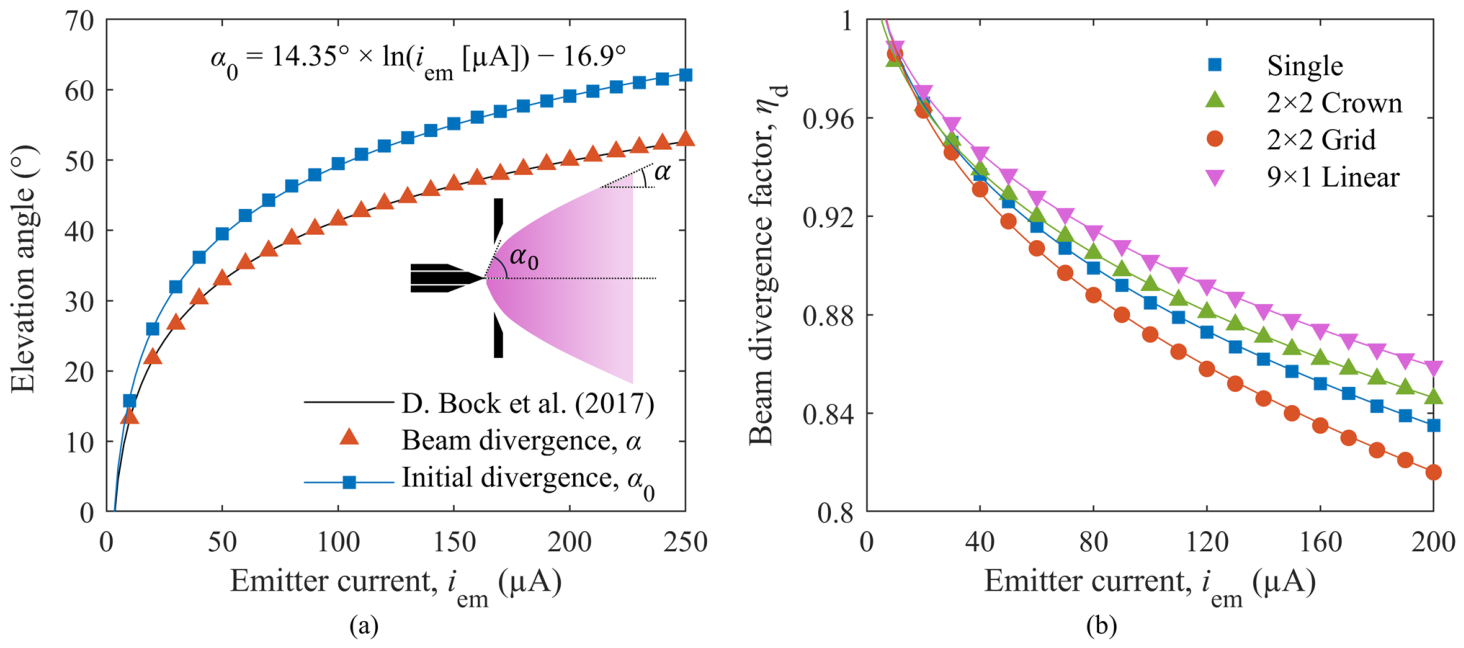
Vasiljevich and Tajmar [32] derived a correlation between the initial beam divergence half angle and the emitter current for an indium ion source. However, an equivalent correlation for a gallium ion source was not available for the present analysis. For the gallium-based NanoFEEP thruster, the final beam divergence half angle, , is given by Equation (9). Because this correlation is specific to the NanoFEEP emitter–extractor geometry, it was not directly applied to the present emitter geometry. Instead, the NanoFEEP geometry [27,33] was reconstructed in the ion-trajectory simulation, and the initial divergence half-angle, , was determined for each emitter current. Specifically, was iteratively varied until the simulated final divergence half-angle reproduced the corresponding value of given by Equation (9). Figure 5a compares the prescribed final divergence half-angle, , with the corresponding values of obtained from the inverse trajectory analysis using the NanoFEEP geometry. Based on these results, the current-dependent correlation for the initial divergence half-angle of the gallium ion beam was derived as Equation (18):
where denotes the emitter current in microamperes. Equation (18) was subsequently used as the initial angular boundary condition for the present emitter geometries.
Figure 5.
Beam divergence characteristics obtained from ion trajectory simulations: (a) empirical beam divergence reported by Bock et al. [27], simulated beam divergence, and fitted initial divergence for the reference NanoFEEP geometry; (b) beam divergence factor of hybrid emitter configurations averaged over azimuthal directions and individual emitters.
The corresponding beam divergence factor () was calculated for eight effective azimuthal directions. The resulting beam divergence factors were then averaged over the azimuthal directions and emitters to obtain the effective beam divergence factor for each emitter configuration, as shown in Figure 5b. In this study, thrust was calculated from the measured emitter and extractor currents and the applied voltage using this effective beam divergence factor. Because the actual beam divergence of a multi-emitter array can be affected by fringe-field effects and emitter-to-emitter interactions, the reported thrust values should be regarded as calculated estimates rather than direct thrust measurements.
4. Results
4.1. Capillary Single-Emitter
A capillary emitter is the simplest emitter geometry that can effectively protect the propellant from contamination while offering a simple fabrication process for FEEP emitter applications. To evaluate its suitability for FEEP multi-emitters, an experimental model of a capillary single-emitter is fabricated and tested under both voltage-control and current-control conditions, revealing three distinct Taylor cone formation modes.
4.1.1. Voltage-Control
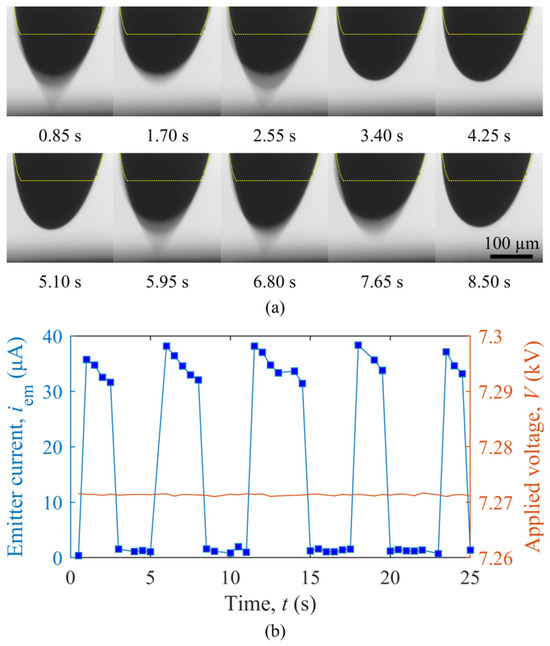
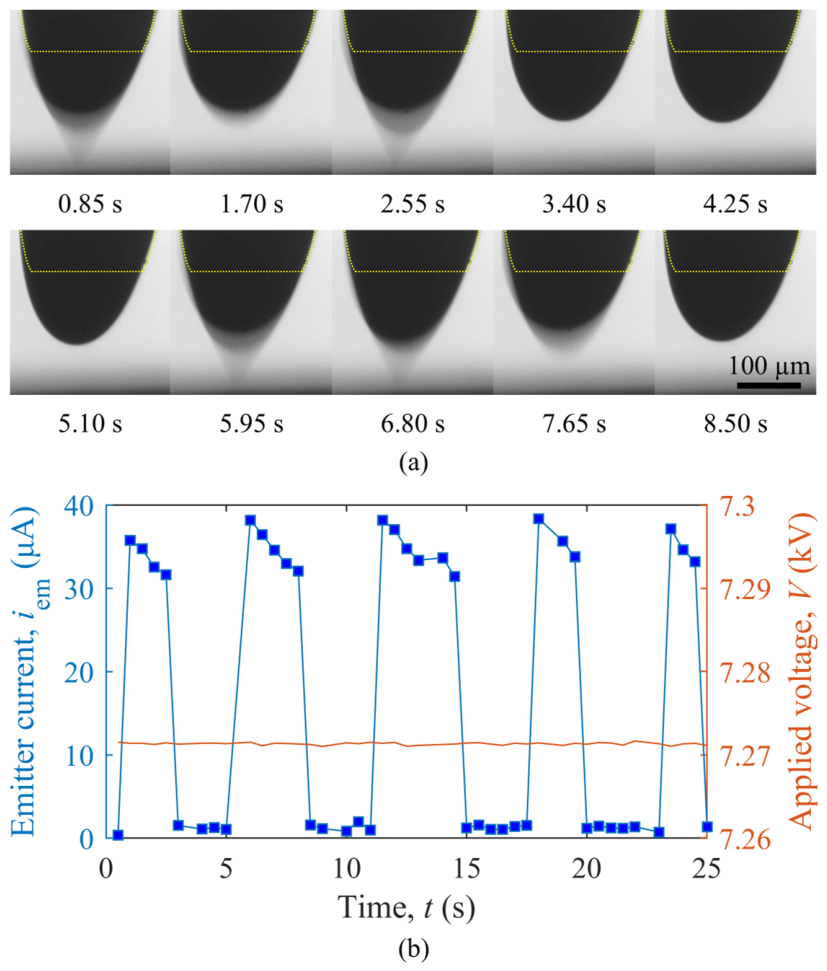
First, the capillary emitter was tested under constant-voltage-control conditions, in which the applied voltage was kept constant while the emitter current varied according to the emission state. Under these conditions, a pulse emission mode occurred, in which the Taylor cone formed periodically in a pulsating manner. In this mode, a gallium droplet maintains a hemispherical meniscus with slow inflation during the idle regime until a pulsating Taylor cone forms, rapidly transitioning between a conical and a round shape, as shown in Figure 6a. The resulting emitter currents exhibit positive half-cycles of a burst rectangular wave, as illustrated in Figure 6b.
Figure 6.
Experimental results of the pulse emission mode: (a) pulsating Taylor cone, where the yellow dotted line indicates the capillary profile obscured by the Taylor cone and meniscus; (b) pulse waveform, where the blue and orange lines correspond to the left and right y-axes, respectively.
The pulsating behavior is attributed primarily to the difference between the voltage required for initial droplet deformation and that required for Taylor cone sustainment. Because the capillary emitter has a relatively large meniscus diameter, a high voltage is required to deform the meniscus and initiate Taylor cone formation. Once a sharp Taylor cone is formed, this voltage exceeds the level required to sustain the Taylor cone, producing an initial emitter current exceeding 30 µA. The resulting mass consumption rapidly collapses the Taylor cone, which subsequently undergoes a continuous cycle of reformation, generating burst-like pulsed emission. A similar mechanism involving current overshoot, depletion of the emitting cone, current extinction, and subsequent cone replenishment has been proposed for liquid-metal ion sources by Thompson and Prewett [34]. As this process continues, the droplet volume decreases, increasing the distance between the droplet surface and the extractor and weakening the local electric field. The emitter current gradually decreases until the Taylor cone can no longer be sustained, as shown in Figure 6b. Continuous gallium resupply during the idle regime then increases the droplet volume and restarts the pulsed emission cycle. However, because the capillary emitter was connected through a 1 MΩ series resistor, the current-dependent voltage drop across the resistor may also have contributed to the extinction and reformation dynamics.
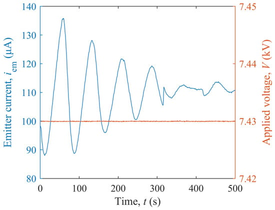
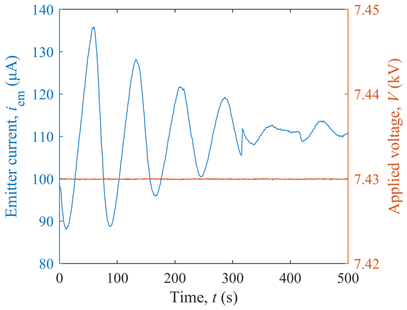
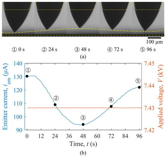
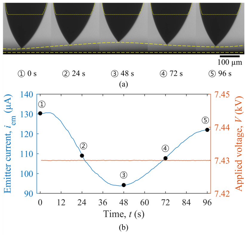
With a slow increase in the applied voltage during pulse emission mode, an oscillating emission mode is achieved, characterized by a repeating damped sine wave, as shown in Figure 7. The correlation between the sequential changes in the Taylor cone–extractor distance, illustrated in Figure 8a, and the damped sine wave pattern, shown in Figure 8b, provides insight into the mechanism behind this oscillatory waveform. Thompson and Prewett [34] similarly attributed post-onset current overshoot and decay in a liquid-metal ion source to transient changes in cone geometry, which modify the apex electric field and consequently the emission current. Due to the inherently intense microdroplet generation and high mass consumption of capillary emitters [25], the Taylor cone height fluctuates during ion emission, which in turn alters the electric field strength at its apex. At the current peak, high mass consumption reduces the Taylor cone height, thereby decreasing the field strength and emitter current. At the trough, reduced emission allows the cone to recover, increasing the field strength and current. When the waveform converges to equilibrium, internal instabilities amplify the oscillations, causing the cycle to repeat. The long timescale of this oscillation suggests that it was governed primarily by the coupled mass-consumption and replenishment dynamics, although a secondary modulation of the effective emitter voltage through the series resistor cannot be entirely excluded.
Figure 7.
Damped sine wave of the emitter current in the oscillating emission mode. The blue and orange lines correspond to the left and right y-axes, respectively.
Figure 8.
Experimental results in the oscillating emission mode: (a) deformation of the Taylor cone with changing Taylor cone–extractor distance, where the yellow dotted line indicates the capillary profile obscured by the meniscus and the yellow long-dashed line indicates the distance between the Taylor cone apex and the extractor plate and (b) emitter current waveform, where the blue and orange lines correspond to the left and right y-axes, respectively.
4.1.2. Current-Control
The pulse and oscillating emission modes primarily originate from the unregulated mass flow rate of the capillary emitter. For the capillary emitter used in this study, the propellant was supplied by passive feeding without active mass flow rate control. As a result, Taylor cone formation and ion emission fluctuated with meniscus oscillations and droplet volume changes. To suppress these fluctuations, a current-control condition was tested, in which the emitter current, and therefore the ion emission rate, was regulated.
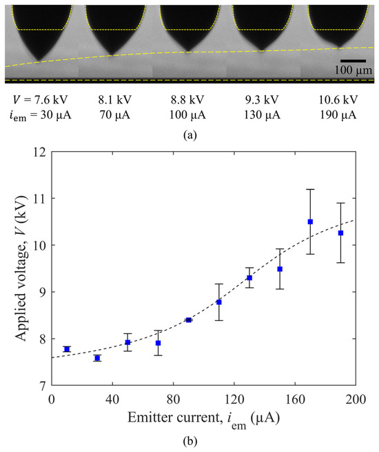
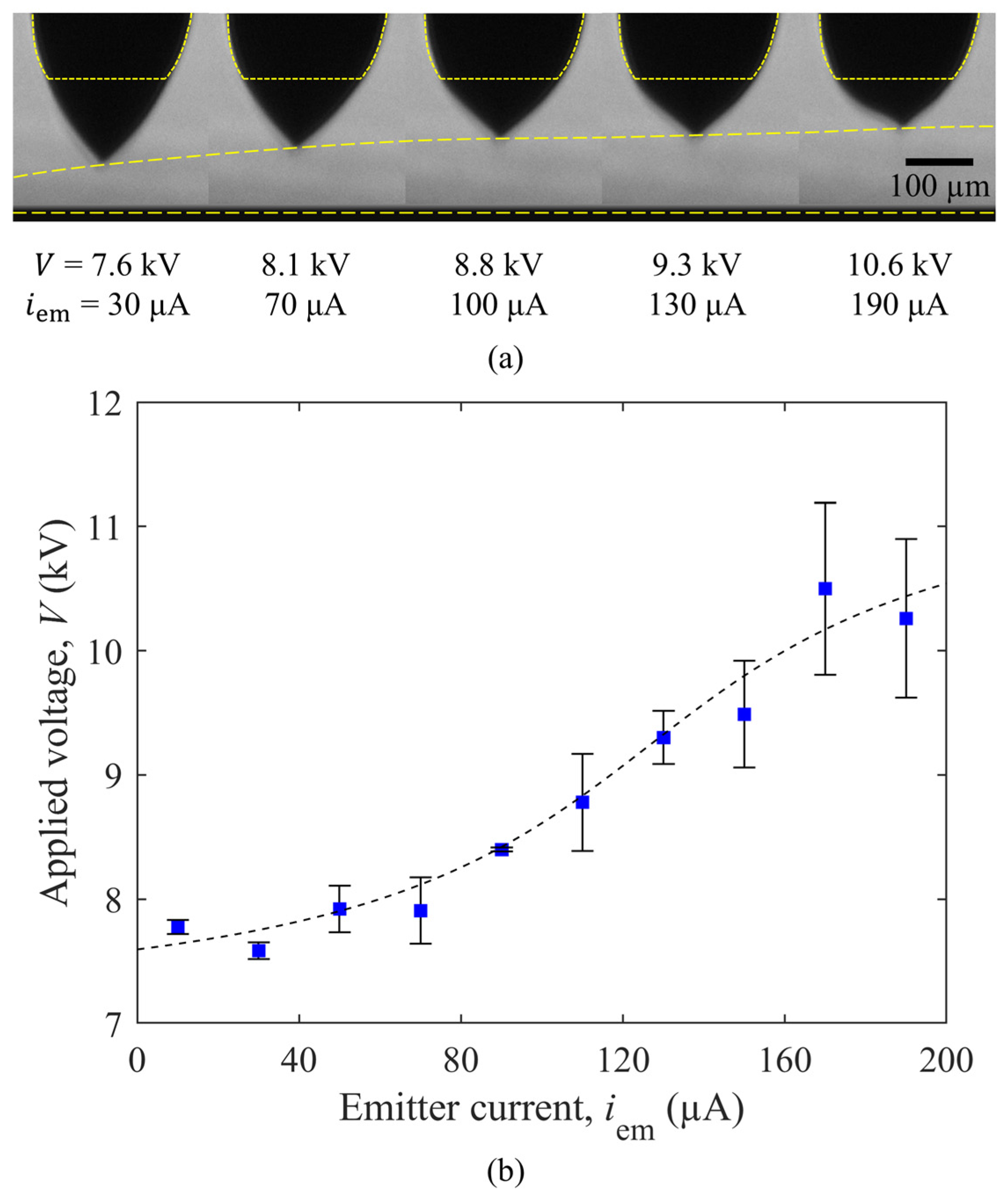
Under current-control, pulse and oscillating modes were significantly suppressed, leading to a continuous emission mode in which both the emission current and applied voltage remained nearly constant. Under the gradually varied emitter current condition, the Taylor cone reached an equilibrium volume and height at each current, as shown in Figure 9a. However, the equilibrium height and volume changed between repeated current cycles because of the slow recovery of the meniscus under passive feeding. In particular, when the emitter current was increased and then decreased, the Taylor cone did not immediately recover to its previous height, resulting in relatively large standard deviations in the measured voltage. The slightly lower mean voltage at 190 µA than at 170 µA is therefore attributed to this delayed meniscus recovery rather than to a reduction in the voltage required for emission. At emitter currents above 70 µA, increased mass consumption reduced the Taylor cone height and weakened the local electric field, resulting in an increase in electrical impedance, as shown in Figure 9b. The apparent electrical impedance was 12.7 MΩ over the 0–200 µA current range, whereas it decreased to 3.6 MΩ when only the emitter-current range below 70 µA was considered.
Figure 9.
Experimental results in continuous emission mode: (a) decrease in Taylor cone height with increasing emitter current, where the yellow dotted line indicates the capillary profile obscured by the meniscus and the yellow long-dashed line indicates the distance between the Taylor cone apex and the extractor plate; (b) current–voltage characteristics for the capillary single-emitter.
In a FEEP multi-emitter configuration, where multiple emission sites are controlled by a single power supply, high electrical impedance is required to improve current uniformity. For a clustered array of single-emitters, an electrical impedance higher than 20 MΩ has been suggested as a reference level for achieving sufficient current uniformity [35]. In addition, a porous needle emitter, which serves as the basic element of a porous crown multi-emitter [12], exhibited an impedance of 14 MΩ in a single-emitter configuration [33]. Since higher impedance also increases power consumption, an electrical impedance range of 14–20 MΩ is considered appropriate for precise current control and uniform emission in multi-emitter configurations. In contrast, the capillary emitter exhibited an electrical impedance of 12.7 MΩ, which decreased to 3.6 MΩ at emitter currents below 70 µA. Therefore, the capillary emitter was considered unsuitable for multi-emitter applications.
4.2. Hybrid Single-Emitter
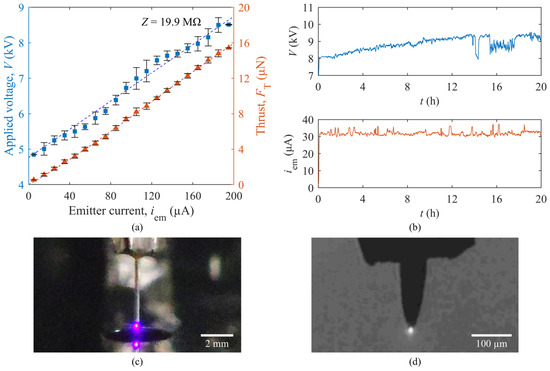
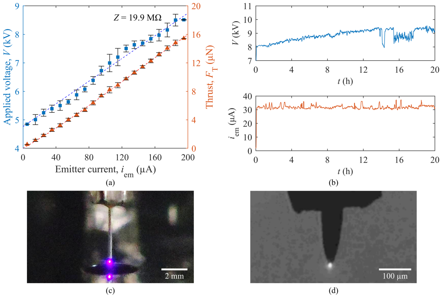
According to Equation (5), reducing the Taylor cone base radius is essential for increasing electrical impedance and reducing current fluctuations during ion emission. In the hybrid emitter, the Taylor cone forms at the tip of the sharply etched tungsten needle, yielding an average cone base radius of 2.22 μm. This radius is substantially smaller than that of the capillary emitter, which is typically in the tens of micrometers range. As a result, the hybrid emitter exhibited current–voltage characteristics with greatly reduced voltage standard deviation, as shown in Figure 10a. The maximum standard deviation of the applied voltage was approximately 0.3 kV in the 100–120 µA current range, corresponding to about 4% of the applied voltage of approximately 7 kV. This reduced standard deviation is attributed to the localized Taylor cone formation at the needle tip, which suppresses meniscus fluctuation and reduces the influence of meniscus height variation on the effective emitter–extractor distance and local electric field distribution. The hybrid emitter exhibited a high electrical impedance of 19.9 MΩ, as shown in Figure 10a. Under both voltage and current controls, the hybrid emitter maintained a continuous emission mode, indicating non-oscillatory emission behavior. During the current–voltage tests, the luminous light from ion emission remained steady at the needle tip, as shown in Figure 10c,d, which confirms well-confined Taylor cone formation and consistent propellant feeding to the needle apex.
Figure 10.
Experimental results of the hybrid single-emitters: (a) current–voltage characteristics and calculated thrust, where the blue squares and orange triangles correspond to the left and right y-axes, respectively; (b) long-term emission test at a controlled emitter current of 30 µA; (c) color image of luminous emission from the emitter used for the current–voltage test; (d) shadowgraphy image of luminous emission at the needle tip during the current–voltage test. Panels (a,b) were obtained from different hybrid single-emitters fabricated during the same study.
To further evaluate the temporal emission behavior of the hybrid emitter, a long-term emission test was conducted using a hybrid single-emitter at a controlled emitter current of 30 µA, as shown in Figure 10b. For this long-term test, a pristine emitter was used, which was distinct from the sample employed to obtain the data shown in Figure 10a. The current–voltage characteristics in Figure 10a were obtained over a short emission duration of less than 30 min, thereby effectively minimizing potential long-term contamination from the vacuum-chamber environment. Although noise was observed in both the measured voltage and current signals, the emitter current remained centered around 30 µA. The emitter voltage remained above approximately 8 kV and gradually increased during the first 10 h, after which it reached a plateau near 9.3 kV. This gradual voltage increase indicates a time-dependent change in the emission condition under low-current operation. Similar voltage increases have been reported in long-term ground tests of liquid-metal ion sources. For example, Tajmar et al. observed an increase in emitter voltage during a 500 h test of a porous tungsten crown emitter and suggested backsputtering contamination from the collector or extractor electrodes as a possible cause [36]. Therefore, the voltage increase observed in the present test may be associated not only with changes in the local emission site or Taylor cone geometry, but also with contamination effects in the vacuum-chamber test environment. Subsequent voltage fluctuations, including the temporary disturbance observed after approximately 14 h, caused only temporary decreases, and the voltage returned to the plateau level without further increase. These fluctuations may be associated with repeated contamination of the emission site by backsputtered material and partial recovery of the liquid-metal surface through ion emission. These results show that the hybrid single-emitter maintained ion emission for 20 h, providing an initial assessment of long-term emission behavior under low-current operation.
The thrust shown in Figure 10a was calculated from the measured current and voltage using the beam divergence factor obtained from the ion trajectory simulations. The calculated thrust of the hybrid single-emitter was 15.9 µN at an emitter current of 200 µA. Its high electrical impedance and non-oscillatory emission behavior indicate the promising performance of the hybrid emitter. Consequently, hybrid emitters were selected for FEEP multi-emitter development.
4.3. Hybrid Multi-Emitter
4.3.1. 2 × 2 Multi-Emitter
Since a major advantage of the FEEP thruster is its ease of miniaturization, maximizing emitter packing density in the multi-emitter is crucial for minimizing system volume. The emitter packing density is determined by the array pattern of the emitters and the arrangement of the extractor holes. To identify the most suitable geometry for the hybrid multi-emitter, a 2 × 2 array of four hybrid emitters was designed, which allows selection between a crown-type or grid-type multi-emitter.
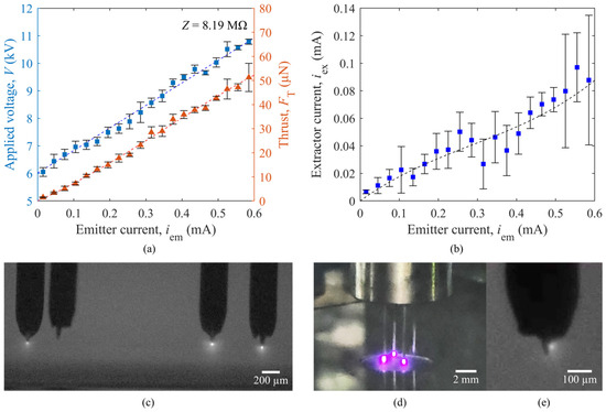
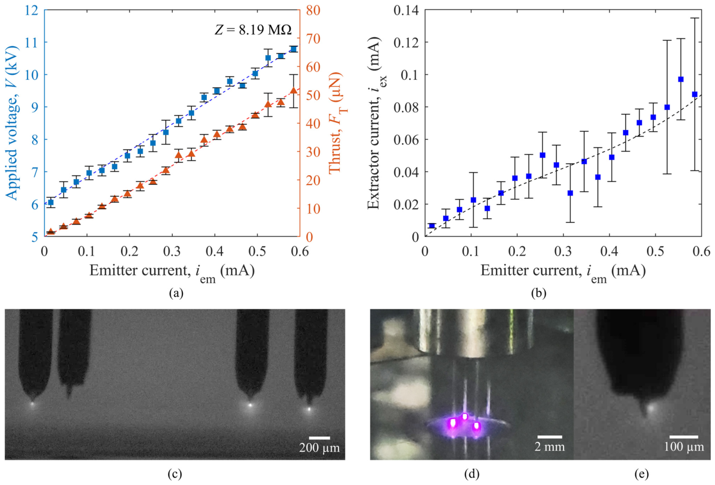
For the crown-type multi-emitter tests, an extractor with a single hole encompassing all emitters was used in the ion emission experiments. The crown-type multi-emitter exhibited well-defined current–voltage characteristics with an electrical impedance of 8.19 MΩ, as shown in Figure 11a. Excluding the contribution of the 1 MΩ resistor, this corresponds to an average electrical impedance of 21.6 MΩ per active emitter. The maximum standard deviation of the applied voltage was approximately 0.37 kV in the 0.27–0.30 mA current range, corresponding to about 4.5% of the applied voltage of approximately 8.2 kV. After accounting for the extractor current shown in Figure 11b, the calculated thrust of the crown-type multi-emitter was 52.2 μN at an emitter current of 0.6 mA, with an active emitter ratio of 75%, as shown in Figure 11c,d. This calculated thrust is 3.28 times higher than that of a single emitter, while maintaining sufficient electrical impedance for uniform multi-emitter operation.
Figure 11.
Experimental results of the crown-type multi-emitter: (a) current–voltage characteristics and calculated thrust, where the blue squares and orange triangles correspond to the left and right y-axes, respectively; (b) extractor current as a function of emitter current; (c) shadowgraphy image of luminous emission at the needle tips; (d) color image of luminous emission from the emitter array; (e) off-tip luminous emission from the needle shaft.
As shown in Figure 11b, the extractor current exhibited relatively large standard deviations. These large deviations are partly attributed to measurement noise associated with the small magnitude of the extractor current and to fluctuating ion interception by the extractor. However, the dominant cause is considered to be unintended ion emission from the needle shaft. Because the crown-type extractor uses a single extractor hole shared by multiple emitters, the electric field became biased toward the edge of the hole, often causing ion emission from the needle shaft in the outer radial direction, as shown in Figure 11e. When this unintended shaft emission occurred, the extractor current increased substantially, degrading the electrical stability. The large standard deviation in the calculated thrust at emitter currents above 0.5 mA is also attributed to the variation in extractor current caused by shaft emissions. Consequently, the crown-type multi-emitter was deemed incompatible with hybrid emitters.
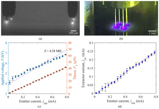
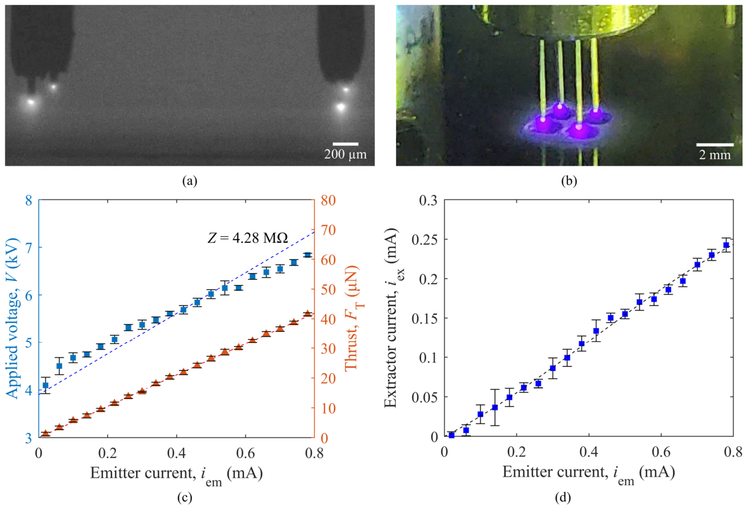
To test the conventional grid array, a grid-type extractor with independent holes aligned to each emitter is used. The extractor hole diameter was reduced to 2 mm, smaller than the conventional 4–4.5 mm, to enhance the emitter packing density of the grid array. Under an axis-aligned electric field, the grid-type multi-emitter achieved an active emitter ratio of 100%, as shown in Figure 12a,b. Figure 12c describes the well-defined current–voltage characteristics of the multi-emitter, with an electrical impedance of 4.28 MΩ. Excluding the contribution of the 1 MΩ resistor, this corresponds to an average electrical impedance of 13.1 MΩ per active emitter. The lower electrical impedance of the grid-type multi-emitter results from a reduced onset voltage due to the smaller extractor hole diameter. The calculated thrust of the grid-type multi-emitter was 41.9 µN at an emitter current of 0.8 mA, which is significantly lower than that of the crown-type multi-emitter despite the higher total current. This reduced thrust is attributed to the decreased operating voltage and increased extractor current caused by the smaller extractor hole diameter. As shown in Figure 12d, the extractor current exhibited smaller deviations than that of the crown-type multi-emitter shown in Figure 11b, but its magnitude was substantially higher. Despite providing uniform emitter activation and axis-aligned emission, the trade-off between emitter packing density and thrust generation makes the grid-type multi-emitter less attractive for FEEP applications.
Figure 12.
Experimental results of the grid-type multi-emitter: (a) shadowgraphy image of luminous emission at the needle tips; (b) color image of luminous emission from the emitter array; (c) current–voltage characteristics and calculated thrust, where the blue squares and orange triangles correspond to the left and right y-axes, respectively; (d) extractor current as a function of emitter current.
4.3.2. Modified Electrical Impedance Model
Based on the experimental results of the 2 × 2 multi-emitters, the applicability of Equation (5) to hybrid multi-emitter configurations was evaluated, and a modified form of the equation was derived. According to Equation (5), the electrical impedances () per emitter for the crown-type and grid-type multi-emitters are estimated to be 29.0 MΩ and 15.2 MΩ, respectively. These values result in relatively large errors of 34.7% and 15.7%, respectively. This discrepancy is attributed to the excessive influence of the onset voltage () in Equation (5). In this equation, is proportional to , which stems from the electrical field effect term, , and the space charge effect term, , in Equation (4). The electric field effect term is expressed as the ratio , allowing the electric field strength to be evaluated consistently for different emitter shapes and extractor geometries. In contrast, the space charge effect term, which was derived from a numerical approach [37], is not normalized by this ratio. As a result, an increase in caused by geometric effects can lead to an overestimation of , even when the Taylor cone base radius and fluid properties remain unchanged.
To correct this overestimation, a voltage increase ratio () is defined using Equation (19):
where is the actual onset voltage of the emitter and is the onset voltage of a needle emitter calculated using Equation (2). To compensate for the excessive contribution of the space charge effect term, Equation (5) was multiplied by , resulting in the modified electrical impedance equation given by Equation (20):
This modification reduces the errors to 2.2% and 0.2% for the crown-type and grid-type multi-emitters, respectively, indicating that the modified equation provides improved agreement with the experimental results.
4.3.3. 9 × 1 Multi-Emitter
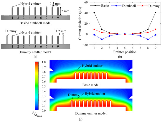
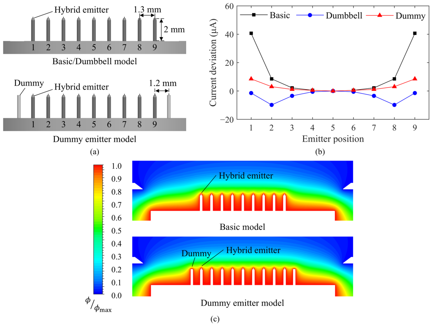
In preliminary experiments using 2 × 2 multi-emitters, the importance of an axially aligned electric field and a large extractor hole diameter was confirmed. Since the conventional crown and grid array approaches could not meet the required performance, a new emitter array pattern is necessary. To achieve the desired conditions, a linear emitter array combined with a slit extractor was designed and evaluated. This configuration offers high emitter packing density while maintaining a 4 mm extractor hole width and a plane-symmetric electric field distribution. To maximize linear packing density while ensuring the minimum margin needed for the needle insertion tool, an interval of 1.3 mm was selected. Figure 13a describes the basic 9 × 1 multi-emitter model with numbered emitters for position identification.
Figure 13.
Design and simulation results of the 9 × 1 hybrid multi-emitter: (a) spacing and emitter numbering for three 9 × 1 array configurations; (b) current deviation from the central emitter; (c) near-emitter electric potential distributions of the basic and dummy-emitter models.
At an average emitter current of 120 μA per emitter, where long-term emission can be maintained without significant emitter degradation, the emitter current deviation relative to the central emitter was analyzed at each position to assess emission uniformity. The emitter current of each position was estimated using Ohm’s law, together with the onset voltages obtained from numerical simulations and the electrical impedance calculated using Equation (20). Although the linear array provides a plane-symmetric electric field, the field remains biased along the slit length, increasing the emitter current at both ends of the array, as shown in Figure 13b. This current concentration at both ends results from the abrupt potential drop near the array ends, as shown in Figure 13c.
To mitigate this field concentration and achieve a uniform emitter current distribution, two approaches were investigated: a dumbbell-type extractor and dummy emitters. The dumbbell-type extractor has large holes at both ends of the slit, as shown in Figure 4b, effectively suppressing electric field concentration and reducing current deviation at the edge emitters, as shown in Figure 13b. However, this configuration also weakens the electric field at the intermediate emitters, causing emitters 2, 3, 7, and 8 to exhibit lower currents than the central emitter. In contrast, dummy emitters, positioned adjacent to the end emitters as shown in Figure 13a, improve the uniformity of the potential distribution, as shown in Figure 13c. This results in a more uniform current distribution across the array, as shown in Figure 13b. Consequently, the dummy emitter model of the 9 × 1 multi-emitter combined with a basic slit extractor was selected as the final configuration, as it provided the most uniform current distribution among the tested designs.
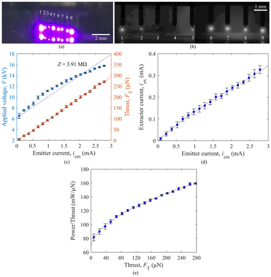
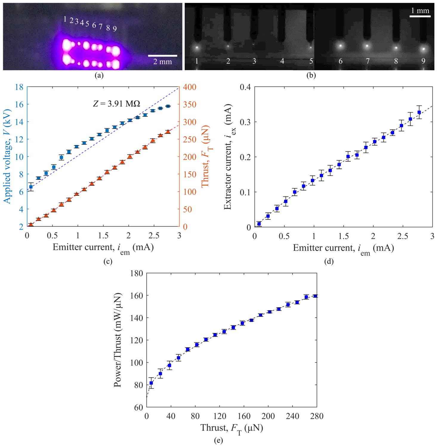
To evaluate the electrical characteristics and thruster performance, a dummy emitter model of the 9 × 1 multi-emitter was experimentally tested. The multi-emitter exhibited an active emitter ratio of 89%, as shown in Figure 14a,b. Although Figure 14a appears to show 16 luminous emission sites, half of them correspond to reflections on the extractor surface. Figure 14c shows the current–voltage characteristics, with an onset voltage of 6.18 kV and an electrical impedance of 3.91 MΩ. Excluding the contribution of the 1 MΩ resistor, this corresponds to an average electrical impedance of 23.3 MΩ per active emitter. The electrical impedance calculated using Equation (20) was 21.7 MΩ, with an error rate of 6.8%, confirming the equation’s reliability. As shown in Figure 14d, the extractor current is lower than that of the crown-type multi-emitter, indicating reduced current loss to the extractor. In addition, the small standard deviation of the extractor current suggests the absence of significant off-axis emission or unintended emission from the needle shaft. The calculated thrust of the multi-emitter was 155.6 µN at an emitter current of 1.6 mA, corresponding to an average current of 200 µA per active emitter. At the maximum tested current of 2.86 mA, the calculated thrust reached 279.0 µN. Figure 14e shows the emitter power-to-thrust ratio (PTR), calculated using Equation (10).
Figure 14.
Experimental results of the dummy emitter model of the 9 × 1 hybrid multi-emitter: (a) color image of luminous emission from the emitter array; (b) shadowgraphy image of emission at the needle tips, with the numbers 1–9 in (a,b) identifying the individual emitters in the array; (c) current–voltage characteristics and calculated thrust, where the blue squares and orange triangles correspond to the left and right y-axes, respectively; (d) extractor current as a function of emitter current; (e) power-to-thrust ratio.
The PTR increased with emitter current, resulting in 134.8 mW/µN at 1.6 mA and 160.4 mW/µN at 2.86 mA. Because part of the input power was dissipated by the 1 MΩ external resistor attached to the power input line, the PTR can be reduced by decreasing this resistance. Assuming that the external resistance is reduced from 1 MΩ to 100 kΩ while maintaining the same emission characteristics, the estimated PTR values decrease to 119.6 mW/µN and 135.2 mW/µN at emitter currents of 1.60 mA and 2.86 mA, respectively.
For comparison, the commercial ENPULSION Nano R3, which employs a porous crown-type indium FEEP emitter, generates a nominal thrust of 350 µN with a total power consumption of 45 W including the neutralizer, heater, and other auxiliaries [38]. At the nominal thrust condition, the average ion current per emission site is approximately 125 µA [39]. Because emitter performance depends strongly on the current assigned to each emission site, the present hybrid multi-emitter was compared at a similar average emitter-current condition rather than by directly comparing the total thrust of arrays with different numbers of active emitters. At an average current of approximately 125 µA per active emitter, the 9 × 1 hybrid multi-emitter consumed approximately 10.9 W of emitter power and produced a calculated thrust of 92.1 µN. If multiple equivalent arrays or clustered units are operated in parallel to reach a total thrust of 350 µN while maintaining the same emitter-level performance, the corresponding emitter power is estimated to be approximately 41.3 W. This value does not include neutralizer, heater, or other system-level power and is therefore not directly comparable to the total power consumption of commercial systems. Nevertheless, it indicates that the emitter-level power consumption of the proposed hybrid multi-emitter is within a feasible range for CubeSat-scale FEEP applications.
MORPHEUS SPACE GO-2, another FEEP-based commercial propulsion system, provides a thrust range of 5–400 µN with a power range of 7–40 W [40]. Since this power includes system-level contributions and the detailed operating-point-dependent thrust–power characteristics are not available, a direct comparison with the emitter-only PTR obtained in this study is limited. In addition, the GO-2 architecture uses individually controlled emitters, whereas the present hybrid multi-emitter is driven as a coupled emitter array using a common power input. Therefore, the present results should be interpreted as an emitter-level demonstration of a simpler multi-emitter architecture rather than as a system-level performance comparison.
The specific impulse of the present hybrid multi-emitter was not directly measured because the propellant mass flow rate was not independently measured during ion emission. However, because the specific impulse of FEEP emitters is closely related to the current assigned to each emission site, the present emitter was evaluated at an average emitter current comparable to the nominal emission-site current of the ENPULSION Nano R3. Therefore, the specific impulse is expected to remain within the high-specific-impulse range characteristic of FEEP-based systems, although direct thrust and mass flow measurements are required for quantitative validation.
5. Conclusions
This study proposed a FEEP multi-emitter using hybrid emitters arranged in a plane-symmetric linear array with dummy emitters at both ends. The emitter, extractor, and array geometries were experimentally investigated to realize uniform emitter-current distribution, high electrical impedance, and a wide thrust capacity. The key findings are summarized as follows:
- The capillary emitter exhibited pulsed (burst rectangular wave) and oscillatory (damped sine wave) emission modes under voltage control, while a continuous mode was achieved under current control. However, its low electrical impedance (3.6 MΩ at emitter currents below 70 µA) indicates limited suitability for FEEP multi-emitter applications.
- In contrast, the hybrid emitter maintained a continuous emission mode throughout the tested conditions and demonstrated a high electrical impedance of 19.9 MΩ, supporting its suitability as a building block for FEEP multi-emitters.
- Comparative tests of 2 × 2 hybrid multi-emitters with crown-type and grid-type extractors revealed that an axially aligned electric field and a large extractor hole diameter are important design requirements for achieving uniform emission in multi-emitter operation.
- Based on these requirements, a 9 × 1 hybrid multi-emitter featuring a plane-symmetric linear array with dummy emitters at both ends and a slit extractor was developed. This configuration achieved an emitter activation rate of 89% with a uniform current distribution.
- The 9 × 1 multi-emitter delivered a maximum thrust of 279.0 µN at an emitter current of 2.86 mA and an emitter PTR of 160.4 mW/µN. These results confirm the feasibility of the proposed hybrid multi-emitter for FEEP thruster applications, particularly for achieving uniform current distribution, wide thrust range, and high electrical impedance.
- For comparison with state-of-the-art FEEP systems, the 9 × 1 hybrid multi-emitter was evaluated at an average current of approximately 125 µA per active emitter, which is comparable to the average ion current per emission site of the ENPULSION Nano R3 at its nominal thrust condition. Under this condition, the hybrid multi-emitter consumed approximately 10.9 W of emitter power and produced a calculated thrust of 92.1 µN. If multiple equivalent arrays or clustered units are operated in parallel to reach a total thrust of 350 µN while maintaining the same emitter-level performance, the corresponding emitter power is estimated to be approximately 41.3 W. Although this value excludes neutralizer, heater, and other system-level power, it suggests that the proposed hybrid multi-emitter has potential as a scalable emitter architecture for FEEP thruster applications requiring uniform current distribution, high electrical impedance, and increased thrust capacity.
Author Contributions
Conceptualization, K.H.K., D.K.S. and H.S.K.; methodology, K.H.K., D.K.S. and H.S.K.; software, K.H.K., D.K.S. and H.S.K.; validation, K.H.K., D.K.S. and H.S.K.; formal analysis, K.H.K., D.K.S. and H.S.K.; investigation, K.H.K.; resources, D.K.S. and H.S.K.; data curation, K.H.K.; writing—original draft preparation, K.H.K.; writing—review and editing, D.K.S. and H.S.K.; visualization, K.H.K.; supervision, D.K.S. and H.S.K.; project administration, D.K.S., K.H.L., J.K. and H.S.K.; funding acquisition, D.K.S., K.H.L., J.K. and H.S.K. All authors have read and agreed to the published version of the manuscript.
Funding
This work was supported by the National Research Foundation of Korea (NRF) grant, funded by the Korea AeroSpace Administration (KASA) [RS-2021-NR056001] and the Korean government (MSIT) [RS-2024-00337022].
Data Availability Statement
The data presented in this study are available on request from the corresponding author.
Conflicts of Interest
Author Jungwon Kuk was employed by the LIG Nex1 Co., Ltd. The remaining authors declare that the research was conducted in the absence of any commercial or financial relationships that could be construed as a potential conflict of interest.
Nomenclature
| Extractor hole diameter (m) | |
| Elementary charge (C) | |
| Electric field strength (V/m) | |
| Electric field (V/m) | |
| Thrust (N) | |
| Geometric constant | |
| Emitter–extractor effective distance (m) | |
| Emitter current (A) | |
| Extractor current (A) | |
| Emitter–extractor vertical distance (m) | |
| Ion mass (kg) | |
| Electrical charge of ion (C) | |
| Taylor cone base radius (m) | |
| Velocity (m/s) | |
| Ion initial velocity (m/s) | |
| Applied voltage (V) | |
| Emitter voltage (V) | |
| Extractor voltage (V) | |
| Onset voltage (V) | |
| Onset voltage of needle emitter (V) | |
| Electrical impedance (Ω) | |
| Greek symbols | |
| Ion beam divergence half-angle () | |
| Initial ion beam divergence half-angle () | |
| Voltage increase ratio | |
| Surface tension (N/m) | |
| Vacuum permittivity (F/m) | |
| Ion beam divergence factor | |
| Taylor cone half-angle () | |
| Density (kg/m3) | |
| Tip radius of curvature (m) | |
| Electric potential (V) | |
References
- Lemmer, K. Propulsion for CubeSats. Acta Astronaut. 2017, 134, 231–243. [Google Scholar] [CrossRef] [Scilit]
- Lev, D.; Myers, R.M.; Lemmer, K.M.; Kolbeck, J.; Koizumi, H.; Polzin, K. The Technological and Commercial Expansion of Electric Propulsion. Acta Astronaut. 2019, 159, 213–227. [Google Scholar] [CrossRef] [Scilit]
- Levchenko, I.; Bazaka, K.; Ding, Y.; Raitses, Y.; Mazouffre, S.; Henning, T.; Klar, P.J.; Shinohara, S.; Schein, J.; Garrigues, L.; et al. Space Micropropulsion Systems for Cubesats and Small Satellites: From Proximate Targets to Furthermost Frontiers. Appl. Phys. Rev. 2018, 5, 11104. [Google Scholar] [CrossRef] [Scilit]
- Kramer, A.; Bangert, P.; Schilling, K. UWE-4: First Electric Propulsion on a 1U CubeSat—In-Orbit Experiments and Characterization. Aerospace 2020, 7, 98. [Google Scholar] [CrossRef] [Scilit]
- Levchenko, I.; Xu, S.; Mazouffre, S.; Lev, D.; Pedrini, D.; Goebel, D.; Garrigues, L.; Taccogna, F.; Bazaka, K. Perspectives, Frontiers, and New Horizons for Plasma-Based Space Electric Propulsion. Phys. Plasmas 2020, 27, 20601. [Google Scholar] [CrossRef] [Scilit]
- Tajmar, M.; Genovese, A.; Buldrini, N.; Steiger, W. Miniaturized Indium-FEEP Multiemitter Design and Performance. In Proceedings of the NanoTech 2002—“At the Edge of Revolution”, Houston, TX, USA, 9–12 September 2002. AIAA 2002-5718. [Google Scholar]
- Marcuccio, S.; Genovese, A.; Andrenucci, M. Experimental Performance of Field Emission Microthrusters. J. Propuls. Power 1998, 14, 774–781. [Google Scholar] [CrossRef] [Scilit] [PubMed]
- Pfeffer, H.A.; Bartoli, C.; von Rohden, H. The electric propulsion activities of the European Space Agency. In Proceedings of the AIAA/DGLR 13th International Electric Propulsion Conference, San Diego, CA, USA, 25–27 April 1978; pp. 78–713. [Google Scholar]
- Genovese, A.; Tajmar, M.; Buldrini, N.; Scheerer, M.; Semerad, E.; Steiger, W. Indium FEEP Multiemitter Development and Test Results. In Proceedings of the 40th AIAA/ASME/SAE/ASEE Joint Propulsion Conference and Exhibit, Fort Lauderdale, FL, USA, 11–14 July 2004. AIAA 2004-3620. [Google Scholar]
- Tajmar, M. MEMS indium FEEP Thruster: Manufacturing Study and First Prototype Results. In Proceedings of the 40th AIAA/ASME/SAE/ASEE Joint Propulsion Conference & Exhibit, Fort Lauderdale, FL, USA, 11–14 July 2004. AIAA 2004-3619. [Google Scholar]
- Lenard, R.X.; Kravitz, S.H.; Tajmar, M. Recent Progress in Silicon-based MEMS Field Emission Thrusters. In Proceedings of the Space Technology and Applications International Forum, Albuquerque, NM, USA, 13–17 February 2005. CP746. [Google Scholar]
- Vasiljevich, I.; Buldrini, N.; Plesescu, F.; Tajmar, M.; Betto, M.; del Amo, J. Consolidation of Milli-Newton FEEP Thruster Technology Based on Porous Tungsten Multiemitters. In Proceedings of the 47th AIAA/ASME/SAE/ASEE Joint Propulsion Conference & Exhibit, San Diego, CA, USA, 31 July–3 August 2011. AIAA 2011-5592. [Google Scholar]
- Krejci, D.; Toller, F.; Schönherr, T.; Koch, Q.; Grimaud, L.; Hugonnaud, V.; Vasiljevich, I.; Reissner, A. Flight heritage of Indium-based FEEP propulsion systems across different applications and orbits: In space cleaning of extractor electrode. In Proceedings of the 38th International Electric Propulsion Conference, Toulouse, France, 23–28 June 2024. IEPC-2024-279. [Google Scholar]
- Loh, N.H.; Tor, S.B.; Tay, B.Y.; Murakoshi, Y.; Maeda, R. Fabrication of Micro Gear by Micro Powder Injection Molding. Microsyst. Technol. 2008, 14, 43–50. [Google Scholar] [CrossRef] [Scilit]
- Momeni, V.; Hufnagl, M.; Shahroodi, Z.; Gonzalez-Gutierrez, J.; Schuschnigg, S.; Kukla, C.; Holzer, C. Research Progress on Low-Pressure Powder Injection Molding. Materials 2023, 16, 379. [Google Scholar] [CrossRef] [Scilit] [PubMed]
- Wright, P.L.; Huh, H.; Uchizono, N.M.; Thuppul, A.; Wirz, R.E. A Novel Variable Mode Emitter for Electrospray Thrusters. In Proceedings of the 36th International Electric Propulsion Conference, Vienna, Austria, 15–20 September 2019. IEPC-2019-650. [Google Scholar]
- Mair, G.L.R. Electrohydrodynamic Instabilities and the Energy Spread of Ions Drawn from Liquid Metals. J. Phys. D Appl. Phys. 1996, 29, 2186. [Google Scholar] [CrossRef] [Scilit]
- Mair, G.L.R. On the Onset Voltage of Liquid Metal Ion Sources. Nucl. Instrum. Methods Phys. Res. Sect. B Beam Interact. Mater. At. 1989, 43, 240–242. [Google Scholar] [CrossRef] [Scilit]
- Mair, G.L.R. Theoretical Determination of Current-Voltage Curves for Liquid Metal Ion Sources. J. Phys. D Appl. Phys. 1984, 17, 2323. [Google Scholar] [CrossRef] [Scilit]
- Taylor, G.I. Disintegration of Water Drops in an Electric Field. Proc. R. Soc. London. Ser. A Math. Phys. Sci. 1964, 280, 383–397. [Google Scholar] [CrossRef] [Scilit]
- Mair, G.L.R. Advances in Liquid Metal Ion Sources Modelling: The Analytical Approach. Nucl. Instrum. Methods Phys. Res. Sect. B Beam Interact. Mater. At. 1994, 88, 435–440. [Google Scholar] [CrossRef] [Scilit]
- Fehringer, M.; Ruedenauer, F.; Steiger, W. Indium Liquid-Metal Ion Sources as Micronewton Thrusters. AIP Conf. Proc. 1998, 456, 207–213. [Google Scholar] [CrossRef] [Scilit]
- Vladimirov, V.V.; Gorshkov, V.N. Stability of Liquid-Metal Ion Sources. Appl. Phys. A 1988, 46, 131–136. [Google Scholar] [CrossRef] [Scilit]
- Vladimirov, V.V.; Badan, V.E.; Gorshkov, V.N. Microdroplet Emission and Instabilities in Liquid-Metal Ion Sources. Surf. Sci. 1992, 266, 185–190. [Google Scholar] [CrossRef] [Scilit]
- Tajmar, M.; Genovese, A. Experimental Validation of a Mass- Efficiency Model for an Indium Liquid-Metal Ion Source. Appl. Phys. A 2003, 76, 1003–1006. [Google Scholar] [CrossRef] [Scilit]
- Tajmar, M. Overview of Indium LMIS for the NASA-MMS Mission and Its Suitability for an In-FEEP Thruster on LISA. In Proceedings of the 32nd International Electric Propulsion Conference, Wiesbaden, Germany, 11–15 September 2011. IEPC-2011-009. [Google Scholar]
- Bock, D.; Spethmann, A.; Trottenberg, T.; Kersten, H.; Tajmar, M. In-Plume Thrust Measurement of NanoFEEP Thruster with a Force Measuring Probe Using Laser Interferometry. In Proceedings of the The 35th International Electric Propulsion Conference, Atlanta, GA, USA, 8–12 October 2017. IEPC-2017-391. [Google Scholar]
- Swanson, L.W. Use of the Liquid Metal Ion Source for Focused Beam Applications. Appl. Surf. Sci. 1994, 76–77, 80–88. [Google Scholar] [CrossRef] [Scilit]
- Malina, F.J. Characteristics of the Rocket Motor Unit Based on the Theory of Perfect Gases. J. Frankl. Inst. 1940, 230, 433–454. [Google Scholar] [CrossRef] [Scilit]
- Cui, Y.; Liang, F.; Xu, S.; Ding, Y.; Lin, Z.; Liu, J. Interfacial Wetting Behaviors of Liquid Ga Alloys/FeGa3 Based on Metallic Bond Interaction. Colloids Surf. A Physicochem. Eng. Asp. 2019, 569, 102–109. [Google Scholar] [CrossRef] [Scilit]
- Shin, J.; Lee, K.H.; Kuk, J.; Ko, H.S. Study on the Improvement of Theoretical and Electric Field Simulation Methods for the Accurate Prediction of FEEP Thruster Performance. Aerospace 2024, 11, 716. [Google Scholar] [CrossRef] [Scilit]
- Vasiljevich, I.; Tajmar, M. The Beam Divergence of an Indium LMIS at a Distance of 50μm as Determined by Plasma Diagnostic Measurements. Ultramicroscopy 2011, 111, 969–972. [Google Scholar] [CrossRef] [Scilit] [PubMed]
- Bock, D.; Tajmar, M. Highly Miniaturized FEEP Propulsion System (NanoFEEP) for Attitude and Orbit Control of CubeSats. Acta Astronaut. 2018, 144, 422–428. [Google Scholar] [CrossRef] [Scilit]
- Thompson, S.P.; Prewett, P.D. The dynamics of liquid metal ion sources. J. Phys. D Appl. Phys. 1984, 17, 2305. [Google Scholar] [CrossRef] [Scilit]
- Genovese, A.; Buldrini, N.; Tajmar, M.; Tamas, E.; Vasiljevich, I.; Marhold, K.; Ruedenauer, F. Indium FEEP Cluster Development. In Proceedings of the 41st AIAA/ASME/SAE/ASEE Joint Propulsion Conference & Exhibit, Tucson, AZ, USA, 10–13 July 2005. AIAA 2005-4385. [Google Scholar]
- Tajmar, M.; Vasiljevich, I.; Grienauer, W. High current liquid metal ion source using porous tungsten multiemitters. Ultramicroscopy 2010, 111, 1–4. [Google Scholar] [CrossRef] [Scilit] [PubMed]
- Langmuir, I. The Effect of Space Charge and Initial Velocities on the Potential Distribution and Thermionic Current between Parallel Plane Electrodes. Phys. Rev. 1923, 21, 419–435. [Google Scholar] [CrossRef] [Scilit]
- Seifert, B.; Engel, W.; Gerger, J.; Koch, Q.; Schönherr, T.; Krejci, D. Direct Thrust Measurement of the Enpulsion Nano R3 Propulsion System on Fotec’s Thrust Test Stand. In Proceedings of the 8th Space Propulsion Conference, Estoril, Portugal, 9–13 May 2022. [Google Scholar]
- Krejci, D.; Reissner, A. The first 100 FEEP propulsion systems in space: A statistical view and lessons learnt of 4 years of ENPULSION. In Proceedings of the 37th International Electric Propulsion Conference, Cambridge, MA, USA, 19–23 June 2022. IEPC-2022-199. [Google Scholar]
- Morpheus Space. GO-2 FEEP-Based Electric Propulsion. Available online: https://www.morpheus.space/ (accessed on 23 July 2026).

Disclaimer/Publisher’s Note: The statements, opinions and data contained in all publications are solely those of the individual author(s) and contributor(s) and not of MDPI and/or the editor(s). MDPI and/or the editor(s) disclaim responsibility for any injury to people or property resulting from any ideas, methods, instructions or products referred to in the content. |
© 2026 by the authors. Licensee MDPI, Basel, Switzerland. This article is an open access article distributed under the terms and conditions of the Creative Commons Attribution (CC BY) license.