


Abstract
The selection of a temperature probe for aerodynamic applications involves a critical trade-off between the measurement accuracy and structural robustness. While the existing literature typically treats thermal performance and structural limits as isolated problems, this study bridges this gap by introducing a novel coupled experimental framework in which the aerodynamic and structural performance of the probes are characterized and interpreted jointly. Three unshielded, cylindrical K-type thermocouples (diameters: D = 0.5, 1.0, and 1.5 mm) were tested in a freejet facility across a Mach number range of M = 0.05 to 0.50, corresponding to a probe Reynolds number range of ReD ≈ 500 to 16,200, at a free cantilever length of L = 70 mm for aerodynamic characterization and L = 20–70 mm for structural characterization. Tests were conducted at a total temperature of approximately To ≈ 291–294 K, continuously monitored throughout each run. The recovery factor was highest for the 0.5 mm probe (r ≈ 0.4–0.55) and comparable for the 1.0 mm and 1.5 mm probes (r ≈ 0.29–0.34), such that the largest diameter did not produce the lowest value. Structurally, the 0.5 mm probe reached its deflection limit at M ≈ 0.22, while the 1.0 mm probe remained stable to M ≈ 0.36, for a free length of 70 mm. By treating probe selection as a constrained selection problem rather than an ad hoc decision, this study provides a quantitative operational envelope—a critical, data-driven framework for researchers to balance sensor accuracy and physical viability in aerodynamic testing.
1. Introduction
The precise measurement of temperature is a cornerstone of experimental fluid dynamics, serving as a critical parameter in applications ranging from gas turbine performance characterization and high-speed wind tunnel testing to combustion diagnostics and validation of computational fluid dynamics (CFD) models [1,2,3]. When a temperature sensor is placed in a high-velocity fluid stream, the temperature indicated by the sensor is not equal to the true static temperature or isentropic total temperature of the fluid. Instead, it reflects a “recovery temperature,” resulting from a complex thermal equilibrium driven by viscous dissipation heating and convective cooling, where accurate thermal characterization is paramount. This recovery temperature arises because a portion of the fluid’s kinetic energy is irreversibly converted into internal (thermal) energy within the boundary layer adjacent to the sensor surface, while the remainder is convected away; the resulting balance between this viscous heating and convective cooling establishes the sensor’s thermal equilibrium. The efficiency of this energy conversion is quantified by the recovery factor (), a dimensionless parameter essential for correcting raw temperature data. Understanding this recovery factor is crucial, and its theoretical underpinnings reveal its dependence on several fluid and flow properties.
Although fundamentally rooted in thermal boundary layer analysis, the theoretical understanding of the recovery factor is complex. It primarily depends on the fluid’s Prandtl number () [4]. While idealized scenarios, such as laminar flow over a flat plate, allow for simple approximations, the reality of cylindrical probes in cross-flow is significantly more complex. The flat-plate case is commonly introduced as a first-order approximation because it isolates the dependence of the recovery factor on within a simple, well-characterized laminar boundary layer; however, it neglects the flow curvature, streamwise pressure gradient, and boundary-layer separation that are inherent to cross-flow over a cylinder, and which are known to govern the recovery factor of cylindrical probes. Recent experimental work has documented substantial azimuthal variation (i.e., a systematic dependence of the local recovery factor on angular position around the cylinder circumference), with surface temperatures varying by position relative to the stagnation point [5]. The practical application of cylindrical probes introduces complexities governed by the interplay of the flow regime, defined by the Reynolds () and Mach () numbers. Of these, only is inherently linked to the probe’s dimensions, through its dependence on the characteristic length scale (the probe diameter); , by contrast, is a property of the free-stream flow and is independent of probe geometry. The two parameters therefore influence the recovery factor through distinct, though coupled, physical mechanisms.
The Reynolds number, for instance, dictates the boundary layer state, separation points, and wake characteristics [6,7], leading to nonlinear changes in the recovery factor. The Mach number further influences the shear layer transition and reattachment. Recent simulations have shown that the effect of the Mach number on the local heat transfer distribution depends strongly on the surface-to-freestream temperature ratio [8]. Physically, and act jointly on the recovery factor: governs the boundary-layer thickness, transition location, and separation behavior that set the balance between viscous heating and convective cooling at the probe surface, while governs the magnitude of kinetic energy available for conversion to thermal energy through compressibility effects. The recovery factor therefore reflects the combined state of the momentum and thermal boundary layers. Furthermore, the recovery factor is sensitive to freestream turbulence levels [9], and recent experiments have revealed that aerodynamic cooling in the wake can produce strongly non-uniform local recovery factors on cylinder surfaces, particularly at higher Mach numbers [10]. Its behavior has also been extensively characterized in historical studies for other geometries and flow regimes, such as supersonic flow over cones [11]. Thus, the thermal behavior of a probe is a complex function of the fluid’s properties (), the flow regime (, , turbulence), and the probe’s own geometry [12,13,14,15].
However, this dependence on the probe geometry introduces a critical design trade-off. While smaller diameter probes are often desired for their faster response times [16,17], higher spatial resolution, and reduced flow blockage, they are inherently more susceptible to bending under aerodynamic load, owing to the dependence of the cross-sectional second moment of area (). It should be noted that the faster response time associated with smaller diameters reflects the sensor’s transient thermal time constant (), which scales approximately with and governs how quickly the probe tracks fluctuating temperatures; this is a distinct physical quantity from the recovery factor addressed in this study, which instead describes a steady-state measurement bias. Here it is worth distinguishing the two roles of geometry: the cantilevered behavior itself arises from the probe’s mounting configuration—fixed at the support clamp and free at the tip—rather than from its diameter; the diameter instead governs the magnitude of the resulting bending deflection for a given cantilever configuration and load, through its strong influence on . In a fluid stream, a probe acts as a cantilevered beam, and aerodynamic drag forces can cause significant structural deflection or flow-induced vibration [18,19,20]. This represents a practical conflict between the desirable transient measurement characteristics and structural robustness. Optimization strategies in engineering often require balancing conflicting objectives, such as structural integrity and aerodynamic efficiency, to identify valid operational limits [21].
While the principles of aerodynamic (thermal) recovery, the viscous heating of a probe surface in a moving fluid stream quantified by the recovery factor r (Equation (3)), and structural loading are individually well-understood, no experimental study has simultaneously characterized these two aspects for standard thermocouple probes as a coupled, diameter-dependent operational envelope, leaving a clear gap in the literature. This gap is consequential because the two performance dimensions are not independent in practice: the same diameter reduction that improves thermal response and spatial resolution simultaneously degrades structural robustness, so a probe selected on purely thermal or purely structural grounds may prove unsuitable once the other constraint is considered. A joint characterization is therefore required to establish which probe geometries are simultaneously accurate and structurally viable for a given test condition. To the authors’ knowledge, this is the first study to characterize the aerodynamic recovery factor and the structural deflection limit of cylindrical thermocouple probes within a single, diameter-resolved framework, rather than treating the two aspects in isolation.
Existing studies typically isolate the problems; they either focus on the detailed aero-thermal analysis and error modeling (e.g., conduction, radiation) of complex, shielded probes [22,23,24,25], or analyze the structural response of cylinders without considering the implications for thermal measurement accuracy. Even recent studies on unshielded probes have focused primarily on their transient thermal response and time constant optimization [26] and on decoupling velocity-dependent recovery errors from conduction errors through advanced calibration techniques [27] rather than their steady-state aerodynamic accuracy and structural limits in a coupled framework. However, thermocouples, which are often favored for their simplicity and rapid response, are particularly vulnerable to these coupled effects, making a comprehensive study of their operational envelope critical.
This study addresses this by treating probe selection as a single constrained selection challenge rather than two separate problems. In practice, this amounts to a structurally constrained selection: for a required free length and target Mach number, the admissible probe diameters are those that remain within their deflection limits, and the recovery factor of the selected diameter is then applied as a fixed calibration correction. Establishing a formal inverse-design procedure over a continuous range of diameters would require a substantially larger dataset and is left to future work. A dual-focus investigation that first quantifies the effect of probe diameter (0.5, 1.0, and 1.5 mm) on the integral recovery factor and, second, experimentally maps the structural deflection limits of these probes is presented. The final objective is to provide a holistic, data-driven “operational envelope” (the safe measurement boundaries in the Mach number–free length parameter space) to guide researchers in making informed, practical decisions for probe selection in subsonic flow experiments.
2. Materials and Methods
2.1. Experimental Facility
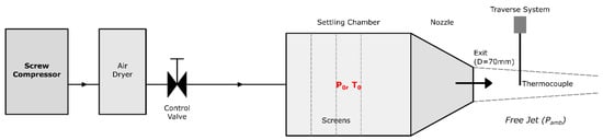
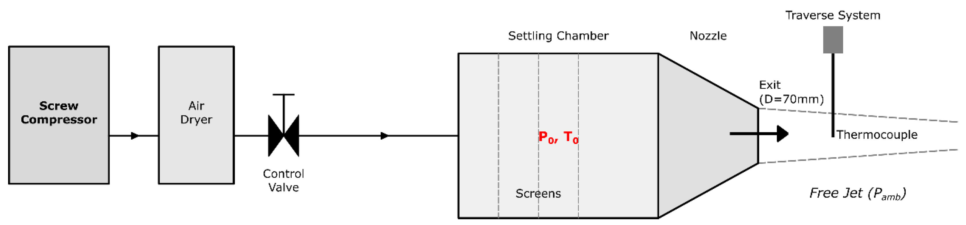
The experiments were conducted in an open-jet wind tunnel at the Calibration and Measurement Technologies Application and Research Center of Eskisehir Technical University. The continuous flow facility is driven by two screw compressors, each rated at 250 kW (Aykom ATV 250 D, İzmir, Türkiye). A 600 mm diameter settling chamber, equipped with honeycomb and multiple screens, ensures low-turbulence, uniform flow to the nozzle inlet. The total temperature and total pressure are measured in this chamber.
An axisymmetric nozzle with an exit diameter of 70 mm accelerates the flow, discharging into the ambient laboratory environment where the pressure is taken as the jet static pressure . The flow Mach number is determined from the measured pressure ratio via the isentropic relations presented in Section 2.3.4 (Equations (1) and (2)), from which the flow velocity is subsequently calculated. The test setup is shown in Figure 1.
Figure 1.
Schematic diagram of the freejet facility.
2.2. Test Articles and Instrumentation
The test articles were commercial, ungrounded, K-type (Chromel–Alumel) thermocouples with an Inconel 600 sheath, which was chosen for its high corrosion resistance and strength. K-type thermocouples are the most widely used thermocouples in experimental aerodynamics, ensuring that the results are of maximum practical utility. Because the recovery factor and structural response are governed by the probe’s external geometry (diameter and sheath material) and flow conditions () rather than the internal junction type, the findings are directly applicable to any sheathed thermocouple of equivalent geometry. This is because the junction configuration primarily governs the internal thermal path and the sensor’s time response, whereas the aerodynamic recovery temperature and the structural deflection examined here are set by the external boundary layer and the beam mechanics of the sheath, respectively. Since neither of these quantities depends on how the thermocouple wires are terminated inside the sheath, the internal junction configuration has only a secondary influence on the results reported here. The probes had nominal outside diameters () of 0.5 mm, 1.0 mm and 1.5 mm, which represent commercially standard sizes spanning a factor of three, providing sufficient resolution to characterize diameter-dependent trends.
The probe was positioned using a motorized 2-axis traversing system. The two axes provide independent control of the probe’s immersion into the jet in the transverse (cross-stream) direction and of its standoff distance from the nozzle exit along the vertical jet axis (the z-axis of the traverse). This system secured the probe and allowed for precise adjustment of the free length ()—defined as the unsupported length of the probe exposed to the flow from the support clamp to the probe tip—relative to the nozzle centerline. For the structural deflection tests, the free length was equivalent to the immersion depth because the probe tip was maintained at the jet centerline in all configurations. The complete test matrix, which includes the specific sensor dimensions and their corresponding aerodynamic and structural testing ranges, is summarized in Table 1.
Table 1.
Summary of experimental parameters and test matrix.
High-fidelity signal digitization was performed using an HBM Genesis HighSpeed Gen7tA data recorder (HBK, Darmstadt, Germany). The thermocouple signals were conditioned using an HBM QuantumX MX1609KB module (HBK, Darmstadt, Germany) that uses internal cold-junction compensation to ensure high thermal stability. A reference RTD (PT100; Elimko, Ankara, Türkiye) was installed in the settling chamber to monitor the total temperature of the flow, whereas the total and static pressures were transduced using Druck ADROIT6200 pressure sensors (Druck, Leicester, UK), which provide an NLH&R (non-linearity, hysteresis, and repeatability) precision of 0.04% span BSL. A complete summary of the measurement instrumentation, including the model and key specifications of each device, is provided in Table 2.
Table 2.
Specifications of the measurement instrumentation used in the study.
All data recording, sensor configuration, and real-time signal visualization were managed using the HBM Perception software (version 7.12; HBK, Darmstadt, Germany). This platform ensured synchronized timestamping across all thermal and pressure channels, allowing for a precise correlation between flow fluctuations and thermal responses. A high-resolution camera (Nikon D7000, Nikon Corporation, Tokyo, Japan) was used to monitor and record the probe deflection during the structural tests.
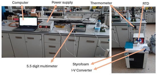
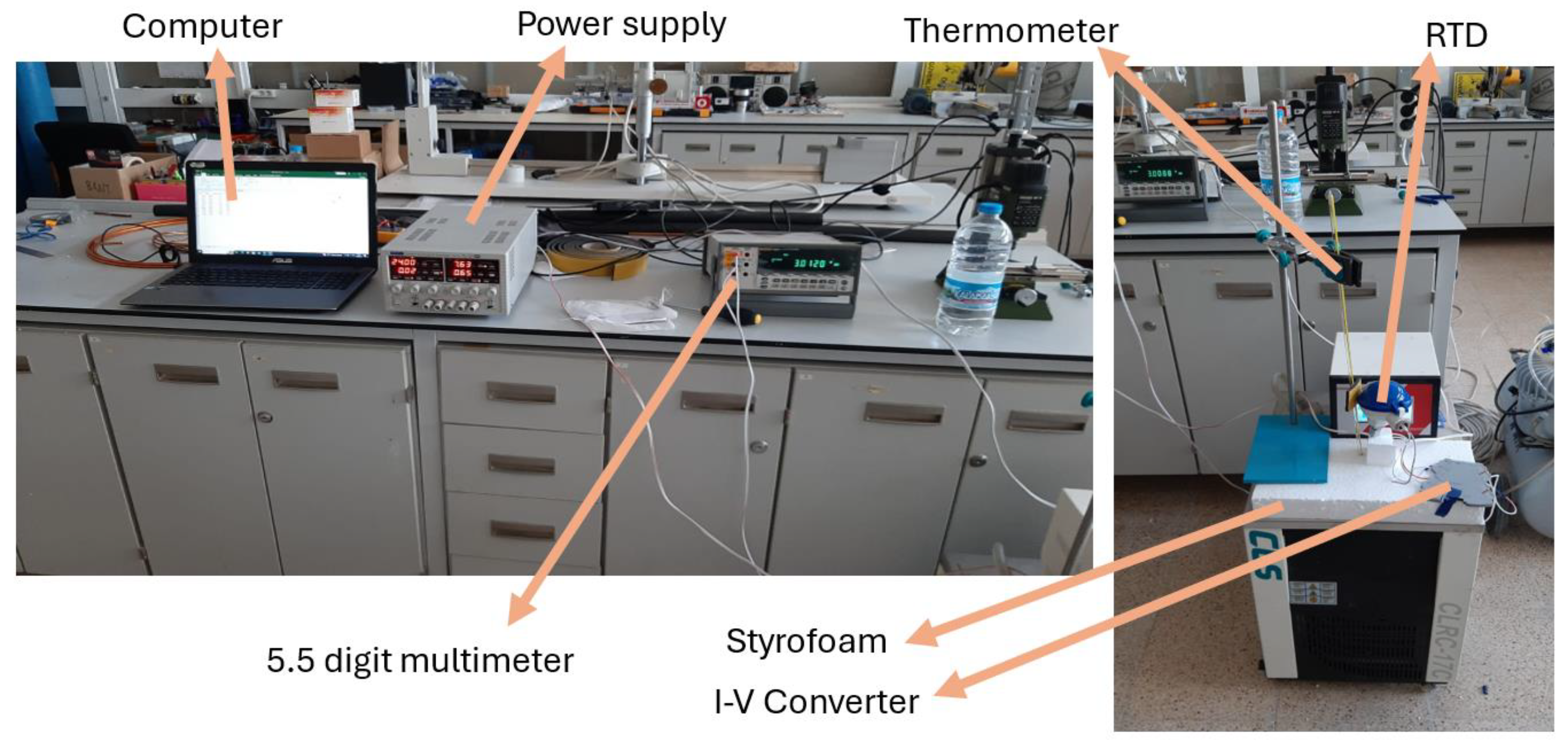
The sensor calibration setup is shown in Figure 2. Calibration was performed over a temperature range that encompassed the experimental conditions. Linear correction equations were derived for each sensor and applied to the raw data during the data reduction phase, ensuring that the reported temperatures reflected the true thermodynamic state within the limits of the reference thermometer’s precision.
Figure 2.
Thermocouple calibration setup.
2.3. Experimental Procedures
2.3.1. Sensor Calibration
Prior to the aerodynamic experiments, all thermocouple probes and the settling chamber RTD (PT100) underwent a rigorous static calibration process to minimize bias errors. The sensors were immersed in a CLS Scientific CLRC-17C refrigerated circulating bath (CLS Scientific, Ankara, Türkiye), which provided a temperature stability of ±0.1 °C via microprocessor-based PID control. To minimize heat exchange with the ambient environment and improve thermal uniformity, the standard metal bath cover was replaced with a Styrofoam lid during calibration. A mercury-in-glass reference thermometer (Alla France, Chemillé-en-Anjou, France) with a scale resolution of 0.1 °C was immersed alongside the sensors as the primary reference standard.
Calibration was performed at six set points spanning approximately 10–50 °C, covering the full range of expected experimental conditions. At each set point, multiple readings were recorded after allowing sufficient thermal stabilization, with the bath temperature remaining within ±0.2 °C of the target value throughout. Linear correction equations were derived for each sensor using least-squares regression, yielding a coefficient of determination of and an RMS residual of 0.16 K. These correction curves were applied to all raw thermocouple data during the data reduction phase, as shown in Figure 2.
2.3.2. Aerodynamic Characterization
For the recovery factor measurement campaign, each of the three probes was positioned at the jet centerline with a fixed free cantilever length () of 70 mm. The Mach number was incrementally varied from 0.05 to the maximum achievable or structurally permissible limit for the probe. Specifically, the aerodynamic characterization spanned for the 1.5 mm probe (bounded by the subsonic ceiling of the campaign), for the 1.0 mm probe, and for the 0.5 mm probe, with the latter two ranges set by each probe’s critical deflection Mach number at = 70 mm (Table 3). At each steady-state condition, , and the indicated probe temperature () were recorded for 60 s.
Table 3.
Critical Mach numbers () for all tested probe diameter and free length combinations.
The aerodynamic characterization was limited to , as this range encompasses the most common subsonic experimental conditions for temperature probe applications. Furthermore, the structural limits of the smaller-diameter probes ( ≈ 0.22 for = 0.5 mm and = 70 mm) preclude recovery measurements at higher Mach numbers for these geometries. The extension of the recovery factor characterization to transonic regimes remains a direction for future work.
The tested conditions correspond to a probe Reynolds number range of , which lies below the critical Reynolds number for the drag crisis of a smooth cylinder, and a Prandtl number of for air.
2.3.3. Structural Deflection Test
Structural deflection tests were conducted for all three probe diameters (0.5, 1.0, and 1.5 mm). Tip displacement was quantified from still images against a millimetric reference scale placed in the plane of the probe within the camera field of view; the deflection was read directly from this scale with a resolution of approximately ±0.5 mm, without digital sub-pixel image processing. For the 1.5 mm probe, no deflection exceeding the 5% deflection threshold was observed across the entire tested Mach number range at any free length configuration, consistent with the analytical prediction of at = 70 mm (Equation (5)). Critical deflection Mach numbers () were therefore only recorded for the 0.5 mm and 1.0 mm probes, as detailed below.
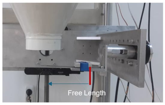
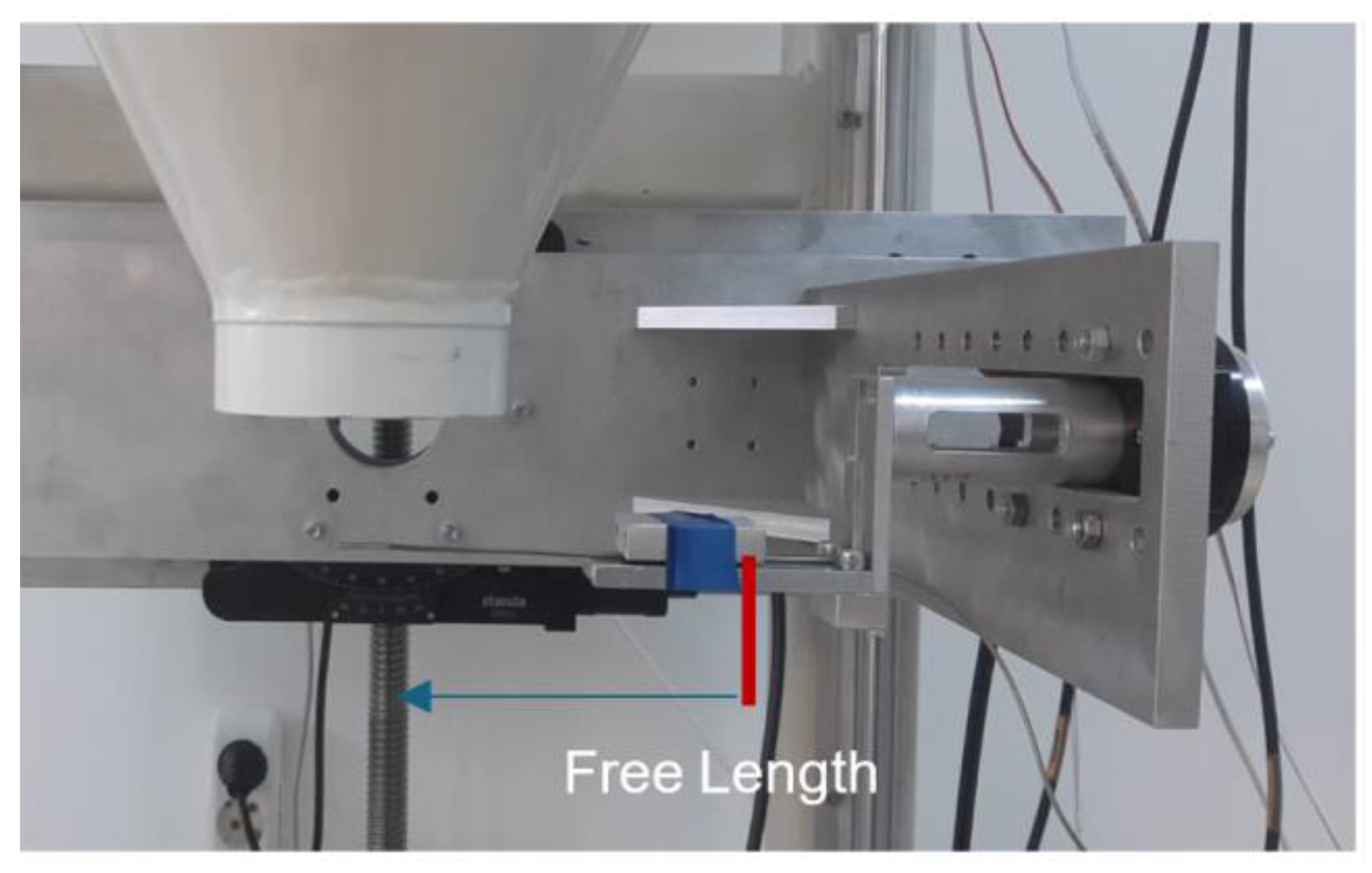
Figure 3 shows the test setup for both the structural and aerodynamic tests. The free length was systematically set to values between 70 mm and 20 mm. For each length, the Mach number slowly increased from a low value until the onset of a significant probe tip deflection. Deflection was monitored using a camera positioned perpendicular to the flow direction, with a reference scale placed within the field of view to enable frame-by-frame displacement tracking.
Figure 3.
Structural and aerodynamic test setup.
The critical condition was defined as the point at which the tip displacement, as measured from the camera imagery, exceeded 5% of the probe’s free length or when flow-induced oscillations became persistent. This 5% deflection limit was selected because it corresponds to a probe tip deviation of approximately 3° from the freestream vector (), at which point the probe’s angle of attack is no longer negligible and the standard calibration assumptions begin to break down.
Beyond this point, the measurement error is driven not only by structural risk but also by the invalidation of the standard calibration curve owing to excessive inclination. The Mach number at which this condition was first met was recorded as the critical deflection Mach number (). The resulting values for all tested diameter and free length combinations are summarized in Table 3.
2.3.4. Data Reduction and Uncertainty
All calculations were performed by assuming that the air behaved as a perfect gas. The Mach number was calculated from the isentropic pressure ratio as follows:
where the ratio of specific heats was taken as . The static temperature was subsequently calculated using the measured total temperature:
The experimental recovery factor was then determined using the measured indicated temperature ():
The specific gas constant for dry air was taken as [28]. The Reynolds number ( was calculated using the local density , evaluated at the static conditions at each measurement point, and the local flow velocity . The dynamic viscosity was evaluated as a function of using Sutherland’s Law with reference constants , , and [28].
An uncertainty analysis was conducted using the Kline–McClintock method [29]. The primary sources of uncertainty were the pressure transducers (±0.04% of reading) and calibrated thermocouples (±0.2 K). The propagated uncertainty in the Mach number was estimated to be less than ±0.002.
The uncertainty in the recovery factor r was propagated from the primary measured quantities () following the same method. Since is itself derived from and the pressure ratio (Equations (1) and (2)), the dominant contribution to arises from the denominator (), which scales as :
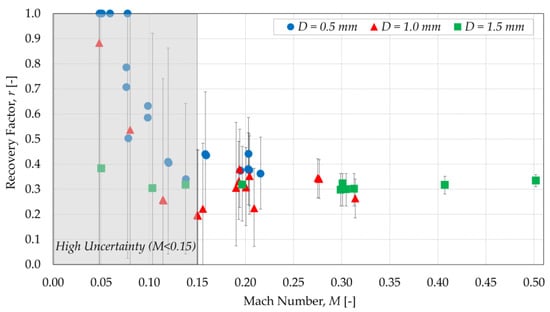
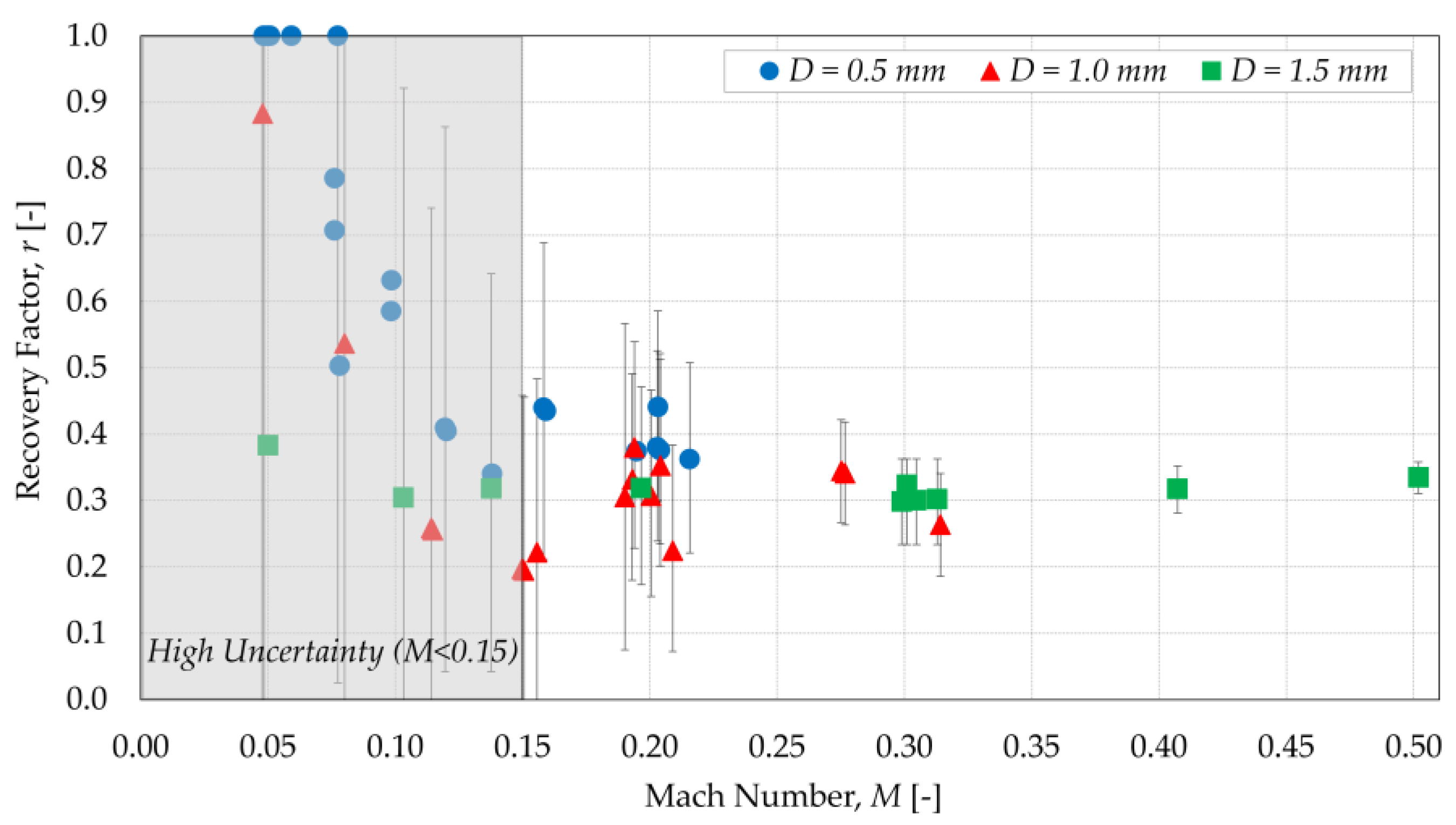
with , the numerator is fixed at approximately 0.28 K, and the uncertainty is entirely governed by the magnitude of the temperature differential. At , —below the thermocouple uncertainty of ±0.2 K—rendering indeterminate in this region. At , still yielding . By , the differential grows to approximately 1.6 K, reducing to , and at , yields . For , the uncertainty bounds stabilize to a physically meaningful range, consistent with the error bars shown in Figure 4.
Figure 4.
Recovery factor (r) as a function of Mach number (M) for thermocouple probe diameters D = 0.5, 1.0, and 1.5 mm at L = 70 mm. Error bars represent the propagated measurement uncertainty. Data points at M < 0.15 fall within the thermocouple measurement uncertainty and should not be interpreted quantitatively.
The uncertainty in the critical Mach number was obtained by propagating the ±0.5 mm displacement-reading resolution through the quasi-static deflection relation. Because the tip displacement grows approximately as near the threshold, the relative uncertainty is , which increases at shorter free lengths where the 5% of threshold displacement is smallest. The resulting bounds range from about ±0.02 at = 70 mm to about ±0.14 at = 20 mm and are reported with the values in Table 3.
3. Results and Discussion
3.1. Aerodynamic Performance: Recovery Factor Analysis
The relationship between the recovery factor, Mach number, and probe diameter is shown in Figure 4. The recovery factor did not decrease uniformly with probe diameter. The 0.5 mm probe exhibited the highest values, in the range of 0.4 to 0.55, whereas the 1.0 mm and 1.5 mm probes were comparable, both lying between approximately 0.29 and 0.34 over most of the tested range, with no consistent ordering between the two. The largest-diameter (1.5 mm) probe therefore did not yield the lowest recovery factor. This non-monotonic behavior shows that the recovery factor cannot be treated as a simple function of diameter and that using a generic value for different probe geometries can lead to significant measurement errors.
Physically, this non-monotonic dependence reflects the diameter dependence of the probe Reynolds number (): at a given Mach number the three diameters sit at different points within the subcritical Reynolds-number range and therefore sample different stages of boundary-layer and wake development around the cylinder, so that the recovery factor reflects the combined influence of diameter and local flow regime rather than diameter alone. As introduced in Section 1, the recovery factor of a cylindrical probe is governed primarily by the fluid Prandtl number, which sets the baseline recovery relation, and is modulated by the Reynolds and Mach numbers through their influence on the boundary-layer state and wake structure. Because probe diameter enters this set only indirectly—chiefly through the Reynolds number at a given velocity—its effect on the recovery factor is not a simple ordered trend, consistent with the behavior in Figure 4. Consequently, since neither the smallest nor the largest probe provides a bounding value across the full range, the recovery-factor correction must be determined for the specific diameter in use.
The extent of the data available for each probe is directly governed by its structural limit. The 0.5 mm probe data terminates at , corresponding to its critical deflection Mach number at = 70 mm, beyond which safe operation is not possible. Similarly, the 1.0 mm probe data extends to , its structural limit at the same free length. For , where only the 1.0 mm and 1.5 mm probe data are available, the 1.5 mm probe maintains a near-constant value of approximately 0.32, while the 1.0 mm probe stabilizes at a comparable level. The two larger diameters differ by less than the measurement scatter, and their relative ordering is not fixed across the tested range.
This stabilization is consistent with the Reynolds number dependency of the recovery factor, as the boundary layer characteristics become less sensitive to the Mach number at higher flow velocities within the subsonic regime.
The scatter observed at low Mach numbers was consistent with the instrumentation limits discussed in Section 2.3.4. For , the data stabilizes markedly across all three probe diameters, with uncertainty bounds converging to a physically meaningful range as shown by the error bars in Figure 4. This value denotes the threshold above which the measurement uncertainty stabilizes; it does not represent a limit of the tested Mach range, which extends, for each probe diameter, up to the structural deflection limits specified in Section 2.3.2. Therefore, interpretations at low Mach numbers should be treated with caution. As detailed in Section 2.3.4, this behavior arises because the temperature differential () that governs the recovery-factor uncertainty scales with and therefore becomes small at low Mach number relative to the fixed ±0.2 K thermocouple uncertainty; the propagated uncertainty in consequently grows as decreases. Accordingly, the region is shaded in Figure 4 to identify the points that lie within the measurement uncertainty and are therefore not interpreted quantitatively.
The results of the present study are consistent with the broader literature in confirming that the recovery factor of cylindrical probes is strongly dependent on the probe geometry and cannot be treated as a universal constant. Kulkarni et al. [9] reported for a mm butt-joint probe at , while Huster and Paymal [5] measured for larger sensors ( = 12.7–14.5 mm) at comparable Mach numbers. These values differ substantially from each other and from those reported here ( depending on diameter), collectively demonstrating that assuming a single correction factor across different probe geometries introduces significant systematic error.
Furthermore, Zditovets et al. [10] showed that local recovery factor distributions on cylinder surfaces can become strongly non-uniform and approach zero near the rear stagnation line at higher Mach numbers, highlighting the additional sensitivity of to flow topology beyond probe geometry alone. These findings collectively motivate the diameter-specific characterization and coupled operational framework presented in this study.
3.2. Structural Performance: Aeroelastic Deflection Analysis
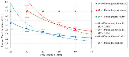
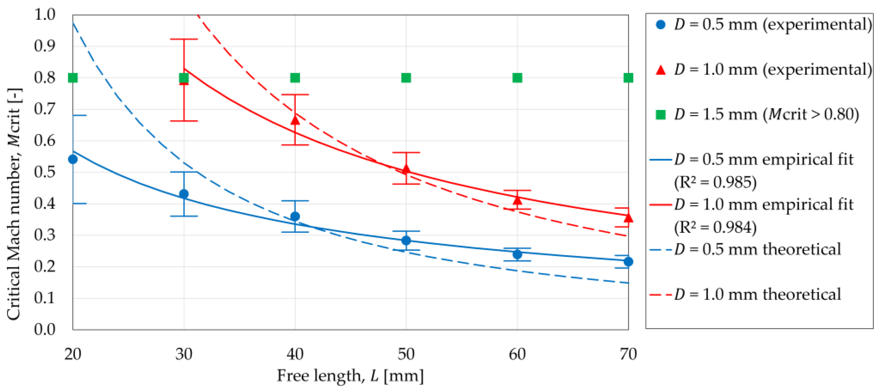
The practical limitations of using smaller-diameter probes are quantified in Figure 5. This plot shows the critical Mach number at which significant deflection occurs as a function of the free cantilever length of the probe. The results were stark: the 0.5 mm probe exhibited a much lower structural limit than the 1.0 mm probe. For example, at a 70 mm free length, the 0.5 mm probe becomes structurally unstable at , while the 1.0 mm probe remains stable up to . Physically, this ordering reflects the competing diameter dependence of the aerodynamic load and the bending stiffness: the distributed drag force grows only linearly with diameter (), whereas the second moment of area, and hence the flexural rigidity, grows with the fourth power (). Consequently, at a fixed flow velocity the tip deflection scales inversely with the cube of the diameter (), so a smaller-diameter probe reaches the 5% of length deflection threshold, and hence its structural limit, at a substantially lower Mach number. This mechanism is quantified by the Euler–Bernoulli model developed below.
Figure 5.
Critical Mach number () as a function of free cantilever length () for 0.5 mm, 1 mm, and 1.5 mm diameter probes.
To validate the experimental deflection limits, a simplified analytical model was applied using the Euler–Bernoulli beam theory. The thermocouple probe was modeled as a cantilever beam subjected to a distributed aerodynamic load. The drag force per unit length, , acting on the cylinder is defined as . For a smooth cylinder in the tested regime the drag coefficient remains relatively constant, and a conservative value of is assumed. The tested Reynolds-number range lies entirely within the subcritical regime, well below the drag-crisis transition () at which falls abruptly. Across this range the smooth-cylinder drag coefficient varies only modestly, remaining within approximately . Because the critical velocity derived from Equation (5) scales as , this ±≈10% variation propagates to only a ±≈5% change in the predicted critical Mach number (e.g., for the 0.5 mm probe at = 70 mm shifts from 0.22 to the range 0.21–0.23). This variation is comparable to the experimental scatter and does not alter any structural conclusion; adopting a fully Reynolds-dependent in place of the constant value would therefore not materially change the operational envelope. Therefore, the maximum deflection is given by:
This model rests on several simplifying assumptions: (i) deflections are small relative to the free length (linear elastic, Euler–Bernoulli regime); (ii) the probe cross-section is uniform and circular along its entire free length; (iii) the sheath material (Inconel 600) is homogeneous and isotropic; (iv) the boundary condition is idealized as perfectly fixed at the clamp and free at the tip; and (v) the aerodynamic load is treated as quasi-static, thereby neglecting any dynamic or flow-induced vibration effects.
Using the properties of the Inconel 600 sheath [30], the model was applied to the limiting case of the 0.5 mm probe at = 70 mm and = 0.22 . The calculated theoretical tip deflection was approximately 8.6 mm. This theoretical value exceeds the experimental 5% threshold (3.5 mm), confirming that the operational envelope is dictated by the fundamental structural mechanics. Equation (5) explicitly shows that for the adopted 5–of-length deflection criterion (), the critical velocity scales as . The experimental data follow the same inverse power-law form; the fitted exponents are, however, somewhat shallower than this ideal −3/2 value. This deviation is consistent with the simplifying assumptions of the beam model (in particular a uniform solid cross-section and a perfectly fixed clamp) and with the assumption of a constant drag coefficient: while that assumption is well justified across the subcritical Reynolds-number range of the measured conditions, it progressively loses validity toward the shortest free lengths, where the corresponding critical velocities approach the compressible regime and the drag coefficient can no longer be treated as constant. The larger deflection-measurement uncertainty at the shortest free lengths contributes further to the deviation. Furthermore, when applied to the 1.5 mm probe at = 70 mm, Equation (5) predicts —well beyond the studied operational limit of = 0.50. This prediction is consistent with, though not independently confirmed by, the experimental observation that no deflection exceeding the 5% threshold was recorded for the 1.5 mm probe at any tested free length or Mach number.
The validity of the quasi-static assumption (v) was assessed by comparing the characteristic aerodynamic forcing frequency with the structural natural frequency of the probe. Modeling the probe as a homogeneous Inconel 600 cantilever, the first natural frequency, with for the clamped–free fundamental mode, is approximately 72 Hz for the most flexible configuration ( = 0.5 mm, = 70 mm). The unsteady aerodynamic load is dominated by vortex shedding at fs = St·U/D; with ≈ 0.2 in the subcritical regime (), this yields ≈ 30 kHz at the corresponding critical condition (), evaluated at the measured static temperature. The shedding frequency thus exceeds the fundamental structural frequency by more than two orders of magnitude (), equivalent to a reduced velocity , far above the range associated with vortex-induced lock-in. A comparable separation () holds for the 1.0 mm and 1.5 mm probes across their tested ranges. The probe therefore cannot follow the high-frequency fluctuating lift and responds essentially only to the time-mean drag, so the deflection is governed by the mean aerodynamic load and the quasi-static treatment in Equation (5) is justified.
Propagating representative tolerances in the drag coefficient (±10%), the elastic modulus (±5%), and the sheath diameter (±2%) through Equation (5), for which the critical velocity scales as , yields a predicted range of for this configuration. As this range brackets the = 0.80 facility limit, the absence of observed deflection is consistent with the model rather than an independent verification of the point value.
3.3. Synthesis: The Operational Envelope
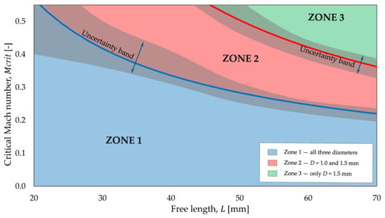
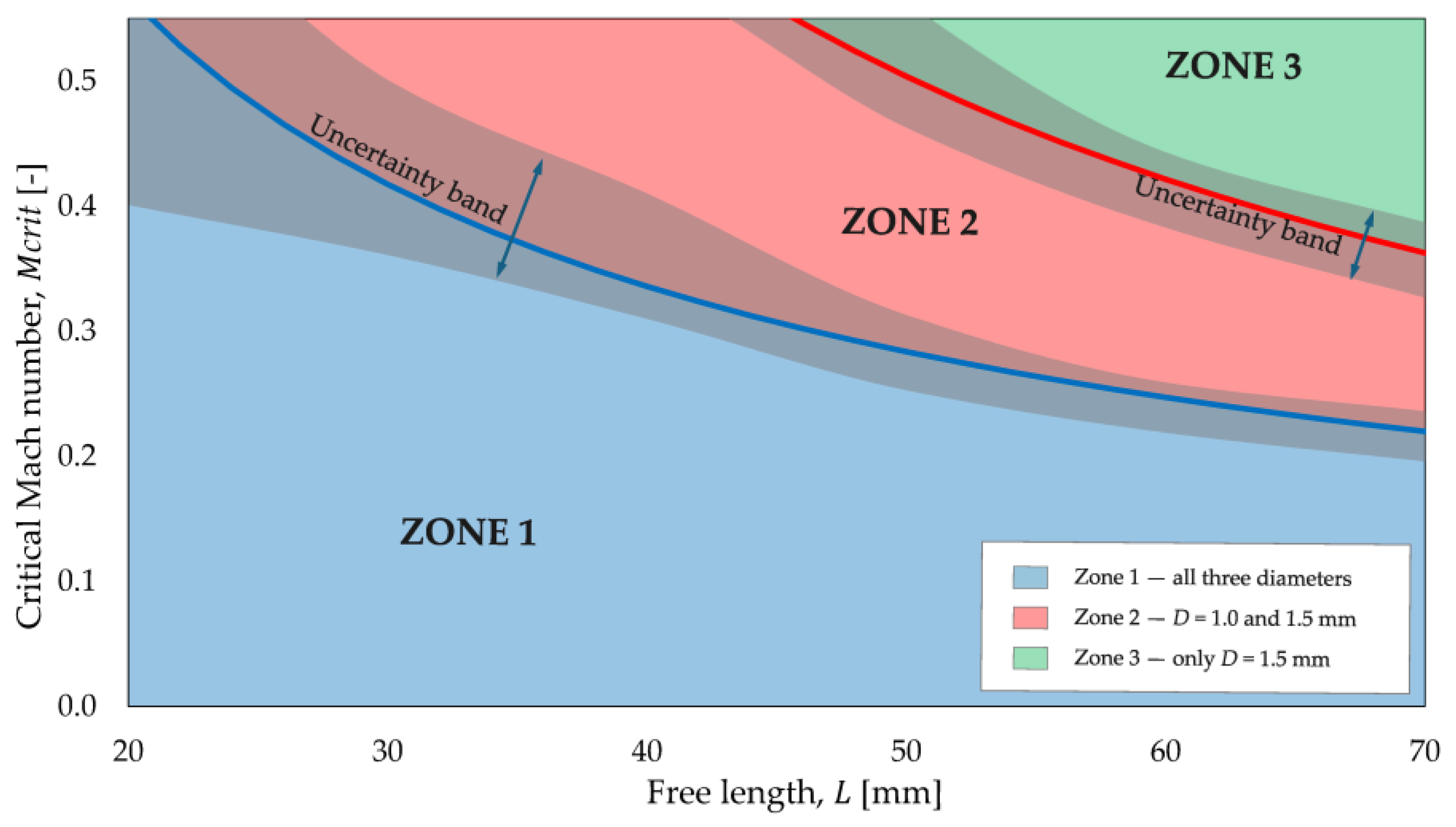
After characterizing the aerodynamic performance and structural limitations of the probes individually, this section synthesizes these findings to present a comprehensive operational envelope. Figure 6 encapsulates the primary contribution of this study, presenting a practical operational map for probe selection. This chart illustrates that the choice of probe is a constrained selection problem. Each boundary of the operational map in Figure 6 corresponds to the fitted critical-Mach-number relation of the respective probe diameter, obtained from the power-law fits in Figure 5. A given operating point, defined by its Mach number and free length, is assigned to a region by comparison with these relations, so that the map derives directly from the critical Mach numbers listed in Table 3 and their fitted trends.
Figure 6.
Operational envelope for Inconel 600 sheathed cylindrical thermocouples. Zone 1: all three diameters structurally viable; Zone 2: only the 1.0 mm and 1.5 mm probes viable; Zone 3: only the 1.5 mm probe viable.
An experimentalist cannot simply choose a probe based on a single desired characteristic (e.g., fast response time of a 0.5 mm probe) without considering the structural limitations. The chart delineates the viable operational spaces for each probe. For example, consider an experiment requiring measurements up to with a necessary free length of 70 mm.
According to the map (Figure 6), a 0.5 mm probe is structurally unsuitable, with its deflection limit reached at . A 1.0 mm probe is similarly insufficient, with at this free length. Therefore, the only viable option is the 1.5 mm probe, which remains structurally stable up to the facility limit of . However, the researcher must then accept and use the specific recovery factor for this probe to ensure accurate temperature correction. This outcome reflects the underlying physical trade-off: at this combination of Mach number and free length, both smaller probes have already exceeded their structural deflection limits, so the 1.5 mm probe is the only geometry for which the aerodynamic measurement remains physically valid. Its recovery factor is therefore not a quantity the experimentalist can optimize, but one that is imposed by the structural constraint and must be applied as measured to obtain an accurate temperature correction. This chart transforms an ad hoc decision into a data-driven engineering choice.
In the present dataset, the practically binding constraint at the tested conditions is predominantly structural: once a probe diameter and free length are structurally viable, its associated recovery factor is fixed and must simply be accepted, rather than optimized. The contribution of the coupled framework is therefore less about actively trading off the two effects against each other, and more about ensuring that a probe selected on structural grounds is not silently assumed to carry a generic, diameter-independent recovery factor. Future work with a wider Mach range or additional diameters may reveal conditions under which the thermal and structural constraints trade off more symmetrically.
Beyond the specific critical Mach numbers and recovery-factor values reported here, the broader physical insight is that probe selection for aerodynamic temperature measurement cannot be governed by thermal accuracy alone. The structural deflection limit depends far more strongly on probe diameter than the recovery factor does, so for small-diameter probes structural viability becomes the binding constraint well before any thermal advantage can be realized. As a general design principle, this implies that thermocouple probes for high-speed applications should be sized primarily against their structural limit at the required free length, with the associated recovery factor then adopted as a fixed, probe-specific calibration correction rather than treated as a free design variable.
The present conclusions and the derived operational envelope are strictly valid within the tested range of . Extrapolation to higher subsonic or transonic Mach numbers is not supported by the current dataset, since compressibility effects on both the recovery factor and the aerodynamic loading (via ) are expected to become more pronounced and cannot be assumed to follow the same trends observed here. Extending the characterization to higher is identified as a direction for future work.
4. Conclusions
This experimental study comprehensively investigated, for the first time in a coupled framework, the aerodynamic and structural performance of cylindrical thermocouples in subsonic flow. The key conclusions drawn from this study are as follows:
- For the tested subsonic range (), the aerodynamic recovery factor r is not constant and is strongly dependent on the probe diameter, but not in a simple ordered way: it was highest for the 0.5 mm probe () and comparable for the 1.0 mm and 1.5 mm probes (), so that the largest probe did not exhibit the lowest value—a variation large enough to introduce significant systematic error if a generic correction factor is assumed.
- The structural integrity of small-diameter probes is a critical operational constraint. The critical Mach number for the onset of aeroelastic deflection follows a strong inverse power-law dependence on free cantilever length (). The observed exponents are somewhat shallower than, but qualitatively consistent with the −3/2 prediction of Euler–Bernoulli beam theory. At = 70 mm, the 0.5 mm probe reaches its deflection limit at , while the 1.0 mm probe remains stable to .
- The selection of a temperature probe is a quantifiable engineering trade-off: smaller diameters offer faster response times and higher spatial resolution but impose severe structural limits, whereas larger diameters provide structural robustness. Because the recovery factor does not follow a simple diameter trend, it does not act as a straightforward penalty for increased size; instead, it must be determined for the specific diameter in use and applied as a fixed calibration correction.
- The operational envelope synthesized in this study provides a practical, data-driven framework for experimentalists to make informed probe-selection decisions. Given a target Mach number and required free length, the envelope directly identifies which probe diameters are structurally viable and what recovery factor correction must be applied, thereby transforming an ad hoc choice into a rigorous engineering decision.
Future work could involve extending the recovery factor characterization to transonic Mach numbers, dynamic analysis to investigate flow-induced vibrations, and direct quantification of the transient thermal time constant (τ). Complementary numerical studies—fluid–structure interaction (FSI) simulations to model the observed deflection phenomena and computational fluid dynamics (CFD) to further validate the recovery factor trends reported here—lie outside the experimental scope of the present study and are likewise left to future work.
Funding
This research received no external funding.
Data Availability Statement
The data that support the findings of this study are available from the corresponding author upon reasonable request.
Conflicts of Interest
The author declares no conflicts of interest.
Abbreviations
The following abbreviations are used in this manuscript:
| CFD | Computational Fluid Dynamics |
| RTD | Resistance Temperature Detector |
| NLH&R | Non-Linearity, Hysteresis, and Repeatability |
| BSL | Best Straight Line |
| PID | Proportional-Integral-Derivative |
| RMS | Root Mean Square |
References
- Eckert, E.R.; Drake, R.M., Jr. Analysis of Heat and Mass Transfer; Hemisphere Publishing Corporation: New York, NY, USA, 1987. [Google Scholar]
- Moffat, R.J. Gas temperature measurement. Temperature Its Meas. Control Sci. Ind. 1962, 3, 553. [Google Scholar]
- Benedict, R.P. Fundamentals of Temperature, Pressure, and Flow Measurements; John Wiley & Sons: New York, NY, USA, 1991. [Google Scholar]
- Schlichting, H.; Gersten, K. Boundary-Layer Theory, 7th ed.; McGraw-Hill: New York, NY, USA, 1979; Chapters 14 and 20. [Google Scholar]
- Huster, A.; Paymal, S. Experimental determination of the recovery factor on cylindrically flow-around temperature sensors Part 2: Determination of the local, tangential surface temperature distribution. Appl. Eng. Sci. 2025, 22, 100210. [Google Scholar] [CrossRef] [Scilit]
- Dominy, R.G.; Hodson, H.P. An investigation of factors influencing the calibration of five-hole probes for three-dimensional flow measurements. J. Turbomach. 1993, 115, 513–519. [Google Scholar] [CrossRef] [Scilit]
- Baidya, R.; Scharnowski, S.; de Silva, C.M.; Awasthi, M.; Kähler, C.J. Investigation of a near-field cylinder wake in the subsonic, transonic, and supersonic regimes. AIAA J. 2023, 61, 5415–5428. [Google Scholar] [CrossRef] [Scilit]
- Kula, A.; Aslangil, D.; Wong, M.L. Compressible and viscous flow over a heated cylinder with varying thermal effects. Phys. Fluids 2025, 37, 016125. [Google Scholar] [CrossRef] [Scilit]
- Kulkarni, K.S.; Madanan, U.; Goldstein, R.J. Effect of freestream turbulence on recovery factor of a thermocouple probe and its consequences. Int. J. Heat Mass Transf. 2020, 152, 119498. [Google Scholar] [CrossRef] [Scilit]
- Zditovets, A.G.; Kiselev, N.A.; Popovich, S.S.; Vinogradov, Y.A. Experimental investigation of the Eckert–Weise effect of pair side-by-side circular cylinders in a compressible cross-flow. Int. J. Heat Mass Transf. 2024, 231, 126061. [Google Scholar] [CrossRef] [Scilit]
- Stine, H.A.; Scherrer, R. Experimental Investigation of the Turbulent-Boundary-Layer Temperature-Recovery Factor on Bodies of Revolution at Mach Numbers from 2.0 to 3.8; NACA Technical Note 2664; National Advisory Committee for Aeronautics: Washington, DC, USA, 1952.
- Eckert, E.; Weise, W. The Temperature of Unheated Bodies in a High-Speed Gas Stream; NACA-TM-1000; National Advisory Committee for Aeronautics: Washington, DC, USA, 1941.
- Morgan, V.T. The overall convective heat transfer from smooth circular cylinders. Adv. Heat Transf. 1975, 11, 199–264. [Google Scholar] [CrossRef] [Scilit]
- Rhodes, R.; Moeller, T.M.; Conner, M.S. Heat transfer to truncated cylinder in cross-flow. Exp. Heat Transf. 2016, 29, 633–648. [Google Scholar] [CrossRef] [Scilit]
- Dogan, B. Numerical investigation of conjugate heat transfer in circular pipes considering wall thickness, material conductivity, and external convection. Results Eng. 2026, 29, 109236. [Google Scholar] [CrossRef] [Scilit]
- Incropera, F.P.; DeWitt, D.P.; Bergman, T.L.; Lavine, A.S. Fundamentals of Heat and Mass Transfer; John Wiley & Sons: New York, NY, USA, 1990. [Google Scholar]
- Straubinger, D.; Illés, B.; Busek, D.; Codreanu, N.; Géczy, A. Modelling of thermocouple geometry variations for improved heat transfer monitoring in smart electronic manufacturing environment. Case Stud. Therm. Eng. 2022, 33, 102001. [Google Scholar] [CrossRef] [Scilit]
- Singhal, D.; Narayanamurthy, V. On the parametric large deflection study of Euler–Bernoulli cantilever beams subjected to combined tip point loading. Int. J. Mech. Sci. 2018, 136, 366–379. [Google Scholar]
- Blevins, R.D. Flow-Induced Vibration; Van Nostrand Reinhold: New York, NY, USA, 1977. [Google Scholar]
- Huera-Huarte, F. Vortex-induced vibration of flexible cylinders in cross-flow. Annu. Rev. Fluid Mech. 2024, 56, 173–196. [Google Scholar]
- Chue, S.H. Pressure probes for fluid measurement. Prog. Aerosp. Sci. 1975, 16, 147–223. [Google Scholar] [CrossRef] [Scilit]
- Glawe, G.E.; Simmons, F.S.; Stickney, T.M. Radiation and Recovery Corrections and Time Constants of Several Chromel–Alumel Thermocouple Probes in High-Temperature, High-Velocity Gas Streams; NACA-TN-3766; National Advisory Committee for Aeronautics: Washington, DC, USA, 1956. [Google Scholar]
- Villafañe, L.; Paniagua, G. Aero-thermal analysis of shielded fine wire thermocouples. Int. J. Therm. Sci. 2013, 65, 214–223. [Google Scholar] [CrossRef] [Scilit]
- He, T.; Zhang, W.; Li, Z.; Zhang, Z.; Gao, F. Conjugate heat transfer analysis and steady-state error model for shielded thermocouples with multi-probes. Int. J. Therm. Sci. 2025, 211, 109702. [Google Scholar] [CrossRef] [Scilit]
- Reardon, J.P.; Schetz, J.A.; Lowe, K.T. Computational modeling of total temperature probes. J. Thermophys. Heat Transf. 2017, 31, 892–903. [Google Scholar] [CrossRef] [Scilit]
- Tagawa, M.; Ohta, Y. Two-thermocouple probe for fluctuating temperature measurement in combustion—Rational estimation of mean and fluctuating time constants. Combust. Flame 1997, 109, 549–560. [Google Scholar] [CrossRef] [Scilit]
- Sánchez de la Rosa, D.; Paniagua, G. Enhancing total temperature measurement accuracy: Calibration procedures and novel two-wire probes. J. Turbomach. 2024, 147, 031008. [Google Scholar] [CrossRef] [Scilit]
- White, F.M. Fluid Mechanics, 7th ed.; McGraw-Hill: New York, NY, USA, 2011. [Google Scholar]
- Kline, S.J.; McClintock, F.A. Describing uncertainties in single sample experiments. Mech. Eng. 1953, 75, 3–8. [Google Scholar]
- Special Metals Corporation. Inconel Alloy 600. Publication No. SMC-027, Huntington, WV, USA, 2008. Available online: www.specialmetals.com (accessed on 26 May 2026).

Disclaimer/Publisher’s Note: The statements, opinions and data contained in all publications are solely those of the individual author(s) and contributor(s) and not of MDPI and/or the editor(s). MDPI and/or the editor(s) disclaim responsibility for any injury to people or property resulting from any ideas, methods, instructions or products referred to in the content. |
© 2026 by the author. Licensee MDPI, Basel, Switzerland. This article is an open access article distributed under the terms and conditions of the Creative Commons Attribution (CC BY) license.