


Abstract
Agile attitude control of nanosatellites is increasingly required for high-resolution imaging, yet actuators that provide agility on larger spacecraft do not scale down well: reaction wheels are torque-limited and slew slowly, while miniaturized control moment gyroscopes (CMGs) deliver high torque but their stored wheel momentum produces a gyroscopic coupling torque that degrades fine pointing—an inherent agility–precision trade-off on low-inertia 3U platforms. This paper presents a two-step variable-speed CMG (VSCMG) strategy that preemptively decelerates the wheel momentum once the attitude error falls below a threshold, attenuating the gyroscopic torque before fine pointing and thus decoupling slewing from precision pointing. It is validated on an experimentally grounded model: a fabricated 1U-class four-CMG pyramid ( mm, 584 g), gimbal dynamics identified experimentally ( fit) and regulated by an integral-type optimal servo, and bench-measured wheel dynamics. At 560 km under aerodynamic and gravity-gradient disturbances, the strategy completes a 90° slew in 25.3 s at a mean slew rate of with accuracy— faster than a reaction-wheel system and more accurate than single-mode CMG operation—with a Lyapunov-based stability guarantee. The spacecraft-level closed-loop performance is established in closed-loop simulation, while the component-level ground experiments verify only that the assumed wheel-speed and gimbal-rate envelopes are achievable on the prototype; the present work is thus a simulation study supported by experimentally identified actuator models, not a system-level experimental demonstration. These results show that momentum-managed VSCMG control substantially relieves the agility–precision trade-off within a 1U envelope under the single-axis 90° slew studied here, extending CMG-class agility to small form-factor satellites previously confined to reaction wheels.
1. Introduction
Since the CubeSat standard was introduced as a low-cost picosatellite platform for education and industry [1], the use of small satellites has expanded rapidly owing to their low cost and short development cycles [2]. As a result, small satellite missions have become increasingly sophisticated, encompassing satellite constellations for global coverage, high-capacity data transmission using optical inter-satellite links [3], and rapid-revisit Earth observation. The importance of attitude control now extends beyond pointing alone: in very-low-Earth-orbit (VLEO) missions the attitude directly governs the aerodynamic interaction with the residual atmosphere, so that attitude stability and control are coupled to orbital operations such as differential-drag maneuvering and orbit maintenance [4]. Agile and accurate attitude control is therefore increasingly central to overall mission performance across a widening range of CubeSat applications. To accomplish such missions, satellites must reorient toward multiple targets distributed over wide areas within a single orbital pass [5]. This requirement demands an attitude control system capable of high-speed, high-precision, and large-angle maneuvers within short timeframes. In particular, emerging applications such as optical communication between low Earth orbit (LEO) satellites require pointing accuracies on the order of 0.1° combined with agile slewing at several degrees per second—a combination that conventional actuator architectures struggle to achieve simultaneously.
Among the actuators available for small-satellite attitude control, reaction wheels (RWs) have been the standard choice for CubeSat-class satellites, offering excellent pointing accuracy. For example, Li et al. [6] reported a design accuracy below 0.008° for a CubeSat RW system, and the on-orbit performance of the Blue Canyon Technologies XACT unit aboard MinXSS-1 confirmed sub-arcminute pointing [7]. Grøtte et al. [8] demonstrated settling times of 1.0–8.25 s with 0.09° threshold accuracy using combined RW and magnetorquer control, while nonlinear RW controllers have achieved 0.04–0.05° accuracy in simulation [9]. Recent flight-readiness frameworks for 3U-class platforms such as INHA RoSAT [10] demonstrate that production-grade RW-based ADCS pipelines can be developed and verified at the CubeSat scale. However, the maximum body rates achievable with RWs are typically below 1°/s, leading to maneuver durations of several minutes for large-angle reorientations—a critical bottleneck for time-sensitive missions.
Beyond momentum-exchange devices (reaction wheels and CMGs) and magnetorquers, a third class of attitude actuator for small satellites has matured rapidly: miniaturized propulsion systems capable of producing thrust in multiple directions. By distributing several thrusters around the spacecraft body or by canting their nozzles, a single micropropulsion module can generate control torques about all three axes in addition to translational , so that the same hardware serves both orbit and attitude control; unlike wheels, thruster torque neither saturates nor accumulates stored momentum. Several such systems have already been operated in space on CubeSat-class spacecraft. The twin 6U MarCO spacecraft (2018), the first interplanetary CubeSats, used a cold-gas micropropulsion module with eight R-236fa thrusters—four dedicated to attitude (reaction) control and four to trajectory-correction maneuvers—to maintain three-axis pointing during their Mars flyby [11]. In low Earth orbit, the 1U UWE-4 satellite demonstrated, for the first time on a 1U CubeSat, electric-propulsion attitude and orbit control using four highly miniaturized NanoFEEP field-emission thruster heads operated in a hybrid scheme with magnetorquers, firing its thrusters in orbit from February 2019 and subsequently performing altitude change and collision avoidance maneuvers [12,13]. Compact electrospray (colloid) thruster arrays, such as the MIT ion-electrospray modules carrying eight emitters for combined two-axis attitude and orbit control, represent a further option for this class [14].
These developments establish multi-directional micropropulsion as a viable attitude-control technology for CubeSats. Propulsion-based control is, however, constrained by finite propellant, a comparatively coarse minimum-impulse-bit resolution, and plume/contamination considerations, which make it best suited to slew and orbit-control tasks rather than the continuous, high-bandwidth fine pointing that is the focus of the present work. The momentum-exchange approach adopted here is therefore complementary to, rather than in competition with, these emerging propulsion systems.
Control moment gyroscopes (CMGs) generate significantly higher control torque than RWs and magnetic torquers by exploiting gyroscopic precession, enabling rapid attitude maneuvers essential for missions requiring frequent reorientation. Consequently, CMGs have been the primary actuators for large spacecraft such as the International Space Station (ISS), where high torque output is particularly advantageous. However, applying CMGs to nanosatellites introduces distinct challenges. In low-inertia platforms such as 3U CubeSats, the high torque output of CMGs can cause severe overshoot, oscillation, and degraded pointing accuracy [15]. The Z-axis moment of inertia of a typical 3U CubeSat (≈0.0067 kg·m2) is approximately five times smaller than the X- and Y-axis values (≈0.034 kg·m2), making the yaw axis particularly susceptible to oscillatory responses when subjected to excessive CMG torque.
Realizing the potential of CMGs at the nanosatellite scale requires addressing several challenges documented in the literature. A persistent challenge in CMG-based systems is the presence of kinematic singularities, where torque cannot be generated in a desired direction due to the geometric configuration of the gimbals. Wie et al. [16] develop the singularity-robust (SR) inverse steering law, and Wie [17] provides a comprehensive treatment of CMG dynamics and steering strategies. Standard reference texts on spacecraft attitude determination and control [18] provide the theoretical foundation. Jung and Tsiotras [19] conduct rigorous experimental comparisons of various CMG steering control laws, evaluating their performance in escaping singular configurations. More recently, Geshnizjani and Fichter [20] introduce a steering law that maximizes online torque capacity, and Pereira et al. [21] propose a convex-allocation approach with a novel singularity metric. While these methods are effective for large spacecraft, directly applying them to nanosatellites often amplifies micro-vibrations and oscillatory responses due to the severe scale gap in the vehicle’s inertia properties.
In parallel, recent advancements have led to the development of compact CMGs tailored for CubeSat-class platforms. Akiyama et al. [22] designed a micro-CMG system for the 50-kg TSUBAME satellite, targeting 90° maneuvers within 15 s, but the system prioritized agility over pointing precision. Gaude and Lappas [23] presented a structural design and analysis of a CMG actuator for CubeSats, demonstrating feasibility at reduced mass and volume. Papakonstantinou et al. [24] explored a gimballed CMG cluster design with singularity avoidance, and subsequently demonstrated a ground-tested Nano-CMG cluster achieving peak rates exceeding 50°/s, though with degree-level pointing error [25]. These developments confirm that miniaturized CMGs can provide superior agility compared to RWs, but they have not yet resolved the fundamental tension between high torque output and fine pointing accuracy.
The variable-speed control moment gyroscope (VSCMG) has emerged as a hybrid actuator that combines the characteristics of a CMG and an RW within a single device. Yoon and Tsiotras [26] analyzed the VSCMG for spacecraft attitude tracking, and Schaub and Junkins [27] provided a comprehensive theoretical framework for VSCMG dynamics. McMahon and Schaub [28] proposed simplified singularity avoidance strategies specifically leveraging the variable-speed degree of freedom. Higashiyama et al. [29] addressed reference-aligned singularity avoidance in pyramid-type VSCMG clusters with experimental verification, and more recent VSCMG developments include double-gimbal extensions [30]. However, conventional VSCMG approaches [26,27] primarily employ wheel acceleration as a supplementary control authority for singularity avoidance or integrated power/attitude tracking, rather than as a mechanism to actively attenuate the gyroscopic torque magnitude during the maneuver itself. Consequently, the gyroscopic torque produced during the slew phase remains at its maximum level when the satellite enters the fine-pointing regime, and the wheel-speed saturation limit further constrains the available acceleration authority once high spin rates have been built up. The resulting overshoot and prolonged settling times are particularly severe in low-inertia nanosatellites, where even modest residual CMG torque excites cross-axis oscillations.
To position the contribution precisely, the proposed method is not a new continuous feedback law but an actuator-level operating strategy, and it is distinct from the families with which it might be confused. (i) Unlike gain-scheduling and adaptive control, which adapt the controller gains or estimated parameters online while the actuator and its stored momentum are unchanged, the proposed scheme keeps the gains fixed and instead alters the physical wheel-momentum level of the plant. (ii) Unlike conventional momentum management null-motion, momentum dumping, which redistributes or offloads momentum while preserving control authority, the proposed scheme deliberately reduces the momentum magnitude to attenuate the gyroscopic coupling torque before fine pointing. (iii) Unlike torque-/input-shaping and reference-governor methods, which shape the commanded torque or reference trajectory, the proposed scheme acts directly on the physical momentum state of the VSCMG. In contrast to conventional variable-momentum VSCMG operation, which uses continuous, always-on wheel acceleration for singularity avoidance or integrated power/attitude tracking (IPACS) [26,27], the present approach uses a discrete, attitude-error-triggered two-level momentum switch (Table 1).
Table 1.
Systematic comparison of prior variable-speed CMG (VSCMG) and variable-momentum/adaptive approaches with the proposed two-step strategy. Only the proposed method reduces the stored momentum magnitude for the explicit purpose of attenuating the gyroscopic coupling torque before fine pointing.
This actuator-level viewpoint also clarifies the relation to recent high-accuracy control research, which largely pursues precision through increasingly sophisticated laws: robust nonlinear designs such as nonfragile super-twisting disturbance-observer-based inverse-optimal control [31], predictive actuator-drive schemes such as model-predictive control of switched-reluctance machines [32], and alternative actuation concepts such as electromagnetic docking/separation [33]. The present work is complementary to all of these: because the two-step modulation acts at the momentum-management level, it is control-law-agnostic and can be combined with such inner-loop laws or actuator drives rather than replacing them. This complementarity, together with the hardware-grounded design-and-validation pipeline, constitutes the novelty claimed here.
The preceding review reveals a clear gap: while miniaturized CMGs and VSCMG theory have each advanced significantly, the agility–precision trade-off intrinsic to applying CMGs to low-inertia 3U platforms has not been adequately resolved. The present work focuses on this central problem and contributes:
- A preemptive switched-momentum control strategy on a VSCMG platform. Unlike conventional VSCMG approaches [26,27] that employ wheel acceleration primarily for singularity avoidance or power tracking—an approach fundamentally limited by wheel-speed saturation when the wheels are already spinning near maximum rate—the proposed two-step control actively reduces the wheel angular momentum once the attitude error falls below a threshold, directly attenuating the gyroscopic torque magnitude before fine stabilization. The variable-speed degree of freedom is exploited as a discrete momentum switch (Phase 1 → Phase 2) rather than as a continuous control input, while the same hardware retains the option for continuous-speed (RW-mode) operation discussed in Section 2.4. This is the primary contribution.
- A hardware-grounded simulation pipeline. The actuator dynamics used in the closed-loop simulations are not synthesized from scratch: the gimbal-motor state-space model was identified experimentally (93.2% time-domain fit) and selected after a systematic PID/LQR/IOS comparison; the wheel-dynamics input was directly bench-measured on the fabricated prototype. This provides a substantially stronger evidentiary base than purely numerical CMG-control studies.
- A 1U-class fabricated CMG module (90 × 90 × 105 mm, 584 g) that defines the actuator-rate constraints in the simulation envelope. Component-level ground testing on the prototype confirms that the wheel-speed and gimbal-rate ranges assumed in the simulations are achievable.
The remainder of this paper is organized as follows. Section 2 presents the materials and methods, organized into a high-level system overview, detailed mathematical modeling and controller design including stability analysis, and descriptions of the specific simulation conditions. Section 3 presents simulation results, evaluating agility and accuracy in both two-step CMG and VSCMG RW modes. Section 4 discusses the implications including practical hardware considerations. Section 5 concludes the paper. Appendix A provides actuator-level feasibility verification.
2. Materials and Methods
2.1. System Architecture and Control Strategy
2.1.1. CMG Hardware Configuration
A CMG consists of two primary components: a spinning wheel and a supporting gimbal. The satellite’s attitude is controlled by utilizing the gyroscopic torque generated when the wheel, spinning at a constant speed, is rotated about the gimbal axis, which is perpendicular to the spin axis.
The developed CMG module (Figure 1) features a centrally positioned wheel with a diameter of 13.4 mm driven by a dedicated motor, with the gimbal actuation motor at the base. High-density brass was selected as the wheel material. Four CMGs were arranged in a pyramidal configuration with tilt angle , ensuring uniform torque distribution across all three body axes [17]. The developed module achieved compact dimensions of 90 mm × 90 mm × 105 mm with a total mass of 584 g, ensuring compatibility with a 3U CubeSat (100 × 100 × 300 mm).
Figure 1.
Computer-aided design (CAD) rendering of the miniaturized CMG module. A laboratory prototype has been fabricated and tested (see Appendix A).
Each wheel has moment of inertia about its spin axis and rotates at angular velocity (), so that the wheel angular momentum magnitude of the ith CMG is . The 4-vector of wheel spin rates is denoted . In nominal operation, all four wheels spin at the same rate, so that for all i. The closed-loop simulations adopt a design-level per-CMG wheel momentum of N·m·s in Phase 1 and N·m·s in Phase 2, the value required to deliver the targeted 90° roll slew at ; this corresponds to a flight-scale wheel approximately an order of magnitude more capable, in inertia and/or spin rate, than the ground-test flywheel. The fabricated g prototype ( kg·m2) reaches N·m·s at ≈10,000 rpm; it is used to validate the achievable gimbal-rate and wheel-speed control envelopes (Appendix A), not to supply the flight momentum itself.
The pyramid configuration is illustrated in Figure 2. The CMG whose wheel angular momentum vector is oriented along the positive Y-axis when the gimbal angle is 0° is defined as CMG1; the remaining CMGs are designated sequentially counterclockwise as CMG2 through CMG4.
Figure 2.
Vector diagram of the four-CMG pyramidal configuration. The four units are mounted on the faces of a pyramid with tilt angle . For the i-th CMG (–4): is the wheel angular-momentum vector, the output torque, the gimbal angle, the gimbal angular velocity, and and the gimbal and spin axes, respectively. are the satellite body axes. CMG1 is defined as the unit whose momentum vector lies along at 0°, with CMG2–CMG4 numbered counter-clockwise.
Because the proposed system targets precision pointing, wheel balancing, machining tolerances, and the resulting micro-vibration are relevant; as these properties pertain to the ground-test prototype, they are quantified at the actuator level in Appendix A.
2.1.2. Two-Step Momentum Modulation
Conventional CMG-based systems face a fundamental trade-off between agility and precision in nanosatellites. To overcome this, we implement a two-step control strategy using VSCMGs operating in two sequential phases.
Phase 1 (High-Torque Agile Maneuver): During large-angle attitude maneuvers, the system operates with the wheel spinning at maximum angular momentum ( N·m·s), generating high control torque for rapid slewing.
Phase 2 (Preemptive Deceleration and Precision Stabilization): When the attitude error falls below a predefined threshold (5.0° in this study), the wheel angular momentum is dynamically reduced to N·m·s. This preemptive deceleration attenuates the CMG output torque prior to target acquisition, suppressing overshoot and enabling smooth transition to fine stabilization.
This approach is distinct from conventional VSCMG strategies in the literature [26,27] in two respects. First, wheel-speed modulation is initiated preemptively based on the attitude error threshold and is specifically directed at attenuating the gyroscopic torque magnitude, rather than employed reactively for singularity avoidance or power tracking. Second, the system does not transition between CMG and RW operating modes but instead continuously modulates the gyroscopic torque level by adjusting the wheel angular momentum, maintaining bidirectional torque authority throughout the maneuver.
The rationale follows directly from the CMG torque model (Equation (5)): the gyroscopic output torque scales with the stored wheel angular momentum h. During Phase 1 the wheels run at high h to deliver the large torque required for a rapid slew. Because this same high torque, acting on the lightly-loaded yaw axis (), is the principal source of the overshoot and cross-axis oscillation observed near the target, the wheel momentum is reduced once the attitude error falls below the threshold. This preemptively lowers the achievable torque magnitude before the satellite enters the fine-pointing regime, attenuating the oscillation at its source while retaining bidirectional torque authority for fine stabilization. A single four-CMG cluster therefore provides high torque early in the maneuver and low, finely controllable torque near the target.
2.1.3. System Control Flow
The integrated control loop (Figure 3) operates as follows: (1) the target attitude quaternion is input; (2) the attitude error is computed; (3) the quaternion feedback controller—a proportional–derivative law acting on the attitude-error quaternion and the body angular rate, defined in Equation (11) (Section 2.2.3)—determines the commanded torque ; (4) the steering law (Equation (7)) computes the gimbal angular-velocity command; (5) the gimbal IOS controller and the wheel speed PID controller generate the voltage inputs; (6) the motors drive the CMG; (7) the resulting torque is applied to the spacecraft dynamics; (8) the sensor and attitude determination block closes the feedback loop.
Figure 3.
Block diagram of the CMG-based attitude control system, showing the quaternion feedback outer loop, steering law, and IOS/PID inner loops.
2.2. Mathematical Modeling and Controller Design
2.2.1. Attitude Dynamics
The rotational dynamics of the satellite are governed by Euler’s equation:
where is the moment of inertia, is the angular velocity, is the CMG output torque, and is the external disturbance. The disturbance vector is modeled as , the sum of aerodynamic drag and gravity-gradient torques, computed at each simulation step from
where is the atmospheric density, S the projected cross-sectional area, the drag coefficient, is the position vector of the center of pressure relative to the center of mass (CoM), the orbital velocity vector and its unit vector, the Earth gravitational parameter, the Earth radius, H the orbital altitude, , , the principal moments of inertia, and , , the small body-attitude angles relative to the orbit frame. Numerical values are listed in Table 2. Both torques are first computed in the orbit-fixed frame and rotated to the body frame at each integration step.
Table 2.
Environmental disturbance parameters at 560 km altitude.
Rather than asserting that the two omitted environmental sources are negligible, their magnitudes were estimated explicitly for the present orbit and geometry. Using the parameters of Table 3 (cross-sectional area , center-of-pressure to center-of-mass offset ), the solar radiation pressure force is , with and reflectivity , which yields . The residual-magnetic torque is ; for an uncompensated residual dipole – and a geomagnetic field – at 560 km, –. For reference, the retained gravity-gradient and aerodynamic torques evaluate to ≈ and ≈, respectively, for the same parameters (Table 3).
Table 3.
Estimated environmental disturbance torques for the 3U spacecraft at 560 km, compared with the CMG control torque.
These estimates show that the solar radiation pressure torque is the smallest of the four sources—an order of magnitude below the gravity-gradient torque—and is therefore safely neglected. The residual-magnetic torque is the most significant of the omitted terms and, for a poorly compensated dipole, can be comparable to or slightly larger than the retained gravity-gradient torque. However, all environmental disturbances lie in the – range, i.e., four to six orders of magnitude below the CMG control torque (–). Over the duration of the rapid maneuver, the angular impulse from the worst case neglected source is at most , more than two orders of magnitude smaller than the body angular momentum exchanged during the slew (). Their omission therefore has no material effect on the maneuver and pointing results reported here. The residual dipole would, on longer time scales, be the dominant environmental disturbance and is the term that the spacecraft magnetic attitude-control system is designed to null; it does not, however, affect the short-duration agile maneuver studied in this work.
The moment of inertia matrix for the 3U CubeSat, assuming uniform mass distribution, is:
The Z-axis (yaw) moment of inertia is approximately five times smaller than the X- and Y-axis values. This pronounced asymmetry makes the yaw axis particularly susceptible to oscillatory responses when subjected to high CMG torque, motivating the two-step control approach.
2.2.2. CMG Torque Generation and Steering Law
The torque generated by the four-CMG pyramid cluster is:
where denotes the gimbal angular velocity vector (not the gimbal angle itself). The Jacobian matrix is then:
where h is the wheel angular momentum magnitude, () is the gimbal angle of the ith CMG, and . Within each control phase, h is held constant by the wheel PID controller, and the CMG output torque (5) is generated solely by gimbal-rate modulation. The complete VSCMG torque expression also contains a wheel-acceleration term , where is the moment of inertia of a single wheel about its spin axis and is the wheel spin-rate vector. is the wheel spin-axis transformation matrix introduced in Section 2.4. During the brief Phase 1 → Phase 2 transition, the wheel speeds change by rad/s over a few seconds, producing a per-wheel torque on the order of N·m—about two to three orders of magnitude smaller than the CMG output (gimbal-rate) torque, which lies in the – N·m range. This wheel-acceleration term is therefore neglected in (5), and is treated only as a kinematic update of h between phases.
is the pseudo-inverse steering law, where is the reference (commanded) torque delivered to the steering law, equal to the controller output under nominal (non-saturated) operation, = .
Proximity to singularity is quantified by the manipulability measure
where is the dimensionless geometric Jacobian and , with at a singular configuration. This is the singularity measure introduced by Wie et al. [16], who recommend augmentation by a singularity-robust (SR) inverse when m falls below a threshold . As quantified later in Section 3, the present 90° roll maneuver passes through two transient near-singular configurations, with during the maneuver, briefly entering the warning region for a cumulative duration of approximately 0.5 s. Although the pseudo-inverse of Equation (7) completed this nominal maneuver, operating so close to the singular manifold is not robust; we therefore augment the steering law with a generalized singularity-robust (GSR) inverse [16]:
Here, and are design parameters—respectively, the baseline damping gain, the damping-schedule rate, the dither amplitude, and the dither frequency—with kept small so that remains symmetric positive definite and the dither does not affect steady-state accuracy. For , the damping is negligible, and Equation (9) reduces to the pseudo-inverse Equation (7); for , it bounds the gimbal-rate demand at the cost of a small, transient torque error, guaranteeing invertibility through the near-singular passage. The effectiveness of this augmentation, and its behavior after a single-CMG failure, are evaluated in Section 3.3 and Section 3.4.
2.2.3. Quaternion Feedback Controller
A quaternion-based feedback controller [34] computes the commanded torque from the attitude error:
where is the vector part of the error quaternion , and , are positive scalar feedback gains.
Stability Analysis. Consider the Lyapunov candidate:
where , with only at equilibrium (, ). Taking the time derivative and substituting Equation (1) with kinematics , under ideal torque tracking () and zero disturbance:
Since , is semi-negative definite. By LaSalle’s invariance principle, the largest invariant set in is the equilibrium, so the nominal system is asymptotically stable. The full closed-loop simulations in Section 3 extend this nominal-stability result to the case of bounded LEO disturbances; convergence remains intact under combined aerodynamic and gravity-gradient torques modeled at 560 km altitude. The above analysis assumes ideal torque tracking () and converges to the unique equilibrium ; the well-known unwinding issue associated with quaternion regulators of the form (11) (i.e., the antipodal point also corresponds to but [34]) was not encountered in the simulations of Section 3, since the initial attitude error remained well within the basin of attraction of throughout the maneuver. Robustness analysis of the switched two-step law under model uncertainties is reserved for future work.
It should be emphasized that this analysis applies to the nominal, fixed-momentum loop under the idealizing assumptions of exact torque tracking () and zero disturbance. It therefore does not constitute a formal stability proof for the complete switched two-step system, nor does it account for gimbal-rate saturation, actuator dynamics, or model uncertainty. The closed-loop simulations of Section 3 provide numerical evidence of convergence in the presence of these effects and bounded LEO disturbances; however, a formal guarantee for the switched law—for example, via a common Lyapunov function or an average-dwell-time argument—remains open and is identified as future work.
2.2.4. Gimbal and Wheel Controllers
System identification. The gimbal motor (including driver and encoder) was treated as a black-box plant and identified through frequency-sweep excitation. A swept-sine voltage of amplitude 6 V was applied with frequency varying from 0.1 to 100 Hz in 0.1 Hz steps, sampled at 400 Hz; this range spans the cutoff frequency of the angular-velocity response. The MATLAB R2023b (The MathWorks, Inc., Natick, MA, USA) System Identification Toolbox yielded the second-order transfer function
where and are the Laplace transforms of the commanded gimbal-motor voltage (input) and the measured gimbal angular velocity (output), respectively. Equation (14) was then converted to the diagonalized state-space form
with
The state corresponds to the fast electrical mode (time constant ms), to the slower electromechanical mode (≈139 ms); both eigenvalues are negative, so the open-loop plant is stable. Model fidelity was evaluated by the standard time-domain fit metric
N is the number of samples in the hold-out validation segment and , , are the measured output, model output, and measured-output mean, respectively. The identified model achieved over a hold-out validation segment, supporting its use as the actuator dynamics model in the attitude simulations. The identification used a single swept-sine excitation (–100 Hz, 6 V amplitude, sampled at 400 Hz), and the fit above is reported on the validation segment. We note that a systematic quantification of the measurement uncertainty and trial-to-trial repeatability, and a validation of the identified model under additional operating conditions (e.g., different excitation amplitudes and a step-input test) were not carried out in the present study; these are acknowledged as a limitation and identified as future work to further strengthen confidence in the actuator model.
The wheel-speed transition used in the closed-loop simulations is the bench-measured time series itself (read directly as the wheel-dynamics input), so no model-fitting error is introduced between the measurement and the simulation input. For reference, the measured 10,000 rpm down-transition is well represented by a first-order response with a time constant s (time-domain fit , RMSE rpm, i.e., of the 5000 rpm span; settling in ≈1.8 s), which is the wheel-momentum slew rate assumed in the two-step transition.
Gimbal controller. An integral-type optimal servo (IOS) controller [35] is employed:
where is the tracking error and , G, , are controller gains. Since the motor starts stationary, and the fourth term vanishes. IOS was selected after comparing PID, LQR, and IOS controllers against the identified gimbal plant under both nominal sinusoidal tracking and step-disturbance conditions; only IOS achieved both the fastest tracking response (≈0.02 s phase lag at 0.5 Hz, vs. 0.31 s for PID and 0.14 s for LQR) and full asymptotic rejection of step disturbances. PID and LQR exhibited residual offsets of °/s and 260°/s, respectively, when subjected to a unit step disturbance, motivating the IOS choice for robust gimbal-rate tracking under in-orbit parameter drift.
Controller tuning and design parameters. For reproducibility, the design of the three candidate gimbal-rate controllers is summarized here and in Table 4; all were designed against the identified plant of Equation (14), i.e., the FAULHABER 1724T006SR gimbal motor with its SC1801S driver and encoder, in the state-space form of Equations (15)–(17). The PID controller was tuned on the identified plant (Ziegler–Nichols seed, then manual refinement) to , , . The LQR gain was obtained by minimizing with diagonal weights penalizing the slow electromechanical mode, giving . The integral-type optimal servo (IOS) of Equation (19) augments the plant with the integral of the tracking error and minimizes
where is the augmented state (the integral of the tracking error together with the plant state x), and , are the state and control weights. This cost, via the algebraic Riccati equation for the augmented system, yields , , and ; since the motor starts at rest, and is inactive. The integral term provides the asymptotic step-disturbance rejection reported below. The integral term provides the asymptotic step-disturbance rejection reported below.
Table 4.
Design parameters and measured performance of the candidate gimbal-rate controllers (identified plant, Equation (14)).
Wheel controller. The wheel angular velocity is regulated by a speed-type (incremental) PID controller:
where is the wheel-command voltage (the drive voltage applied to the wheel motor), is the wheel angular-velocity tracking error, and are the wheel-PID gains—distinct from the gimbal-PID gains introduced above. This velocity-form PID avoids integral wind-up during sustained operation. The PID gains were calibrated directly on the prototype wheel motor; the resulting closed-loop response ( transition) was used as the wheel-dynamics input to the attitude simulations described in Section 3.
2.3. Two-Step Control Implementation
A 90° roll maneuver from rest was simulated, with all gimbals initialized to , corresponding to an initial manipulability . The wheel angular momentum was set to N·m·s (Phase 1) and N·m·s (Phase 2), with the two-step transition triggered at 5.0° attitude error. The closed-loop simulation used a sampling time of 0.01 s. Target criteria were angular velocity °/s and accuracy . Control gains are listed in Table 5.
Table 5.
Quaternion-feedback gains for the closed-loop simulations.
For comparison, a conventional RW system was simulated:
where is the RW output torque. The RW array was modeled as three independent wheels mounted along the body X, Y, Z axes, each with diameter 90 mm; the total assembly mass was 540 g. Each wheel was assigned a maximum angular momentum of N·m·s, with peak torque N·m, consistent with COTS CubeSat-class RW units [6,7]. The same quaternion feedback law (11) was used, with gains listed as the “RW baseline” row of Table 5; the controller was implemented in body-axis form, taking advantage of the diagonal allocation.
The switching threshold must satisfy two competing requirements. It must be large enough that the wheel-momentum transition (), which has a finite time constant of order one second, is initiated before the satellite enters the fine-pointing regime, yet small enough that the high-torque, high-momentum Phase 1 covers essentially the whole slew so that agility is preserved. A threshold of 5° sits well above the fine-pointing band (final accuracy ∼0.4°) while leaving more than 94° of the 90° maneuver to Phase 1; its adequacy is examined parametrically in Section 3.5.
2.4. RW Mode in VSCMG
In the RW mode, all four gimbals are held at fixed angles, and attitude control is performed solely through wheel acceleration/deceleration. The pyramid-mounted wheels still possess spin axes that are tilted with respect to the body axes, so the body-frame torque vector is obtained by the linear transformation
where is the 4-vector of wheel-axis torque magnitudes, with the torque produced by the ith wheel along its spin axis, and
The columns of are the wheel spin-axis unit vectors , obtained by integrating the corresponding columns of the Jacobian (6) with respect to ; each column of is a unit vector by construction, ensuring consistency with angular-momentum conservation. With gimbals held fixed, the rate of change in the total wheel angular momentum projected onto the body frame reduces to
Note that in (25) refers to the body-frame angular momentum rate of the four pyramid-mounted VSCMG wheels operating in fixed-gimbal mode and is conceptually distinct from in (22), which describes the three body-axis-aligned reaction wheels of the conventional 3-RW baseline. The two configurations differ in actuator topology (4-wheel pyramid vs. 3-wheel orthogonal), in redundancy (4D wheel-axis space mapped to 3D body via vs. direct body-axis allocation), and consequently in the form of their closed-loop dynamics; only play analogous roles. For completeness, the closed-loop attitude dynamics in VSCMG RW mode read
A 15° roll maneuver was simulated to characterize the fine-pointing capability available in RW mode. The simulation was initialized with the satellite at rest, all four wheels at zero spin rate (), and the gimbals locked at δ = [75°, 15°, 75°, 15°]. This gimbal configuration was chosen because the resulting four spin-axis vectors span the 3D body frame with comparable conditioning of , preserving full 3-axis torque authority during the RW-mode test. The closed-loop attitude controller used the quaternion feedback law (11) with gains and (4th row of Table 5) and a sampling time of 0.01 s, identical to the closed-loop sampling time used in the two-step simulations of Section 2.3.
3. Results
All attitude-control results reported in this section are obtained from closed-loop numerical simulation; the spacecraft-level closed-loop performance has not been demonstrated experimentally. The ground experiments of Appendix A validate only the actuator-level envelopes (the achievable wheel-speed and gimbal-rate ranges), which are used as constraints and inputs to these simulations.
3.1. Two-Step Control Performance
3.1.1. Baseline (Without Two-Step)
Figure 4 shows the satellite attitude response without two-step control. The roll angle converged at s but exhibited an undershoot of 5.17°, while the yaw angle oscillated with an amplitude of approximately 3.3°, failing target criteria. The yaw oscillation is a direct consequence of the inertia asymmetry (Equation (4)).
Figure 4.
Satellite attitude response without two-step torque control, showing undershoot in roll and oscillation in yaw.
3.1.2. With Two-Step Control
Figure 5 shows the results with two-step control. The target attitude was achieved at s with a mean slew rate of (i.e., 90°) and a final pointing accuracy of , satisfying both target criteria. The body-rate profile is near-trapezoidal—the rate is held close to its mean value over the bulk of Phase 1 by the gimbal-rate actuation limit—rather than the smooth exponential typical of unsaturated quaternion feedback, so the peak and mean body rates are comparable. The wheel angular momentum trajectory shown in Figure 5c is not a purely synthetic curve: the velocity-form PID controller (Equation (21)) was first calibrated on the fabricated CMG prototype, and the measured wheel response was used as the prescribed wheel-dynamics input (i.e., a hardware-anchored rather than hardware-in-the-loop simulation). The wheel angular momentum thus remained at N·m·s during Phase 1 and converged to N·m·s at s, in close agreement with the bench-measured time constant.
Figure 5.
Attitude control performance with two-step torque modulation: (a) attitude angle error; (b) gimbal angles; (c) wheel angular momentum transition; (d) manipulability measure . The dashed red line indicates the conventional Wie threshold [16]; the system briefly enters this region twice ( during the maneuver).
3.1.3. RW Baseline
Figure 6 shows the RW system converging at s with angular velocity 0.78°/s and accuracy . The two-step CMG system achieves a 4.5× improvement in slew rate at the cost of reduced accuracy.
Figure 6.
Attitude response of the satellite controlled by a conventional RW system.
Table 6 summarizes the quantitative performance comparison.
Table 6.
Quantitative comparison of attitude control performance.
3.2. RW-Mode Accuracy
Figure 7 shows the attitude error and wheel rotation speed in VSCMG RW mode. The roll attitude converged monotonically (no overshoot) to within 0.1° at s and reached a final steady-state accuracy of 0.013° (worst-case error during the last 10 s of simulation). The wheel speeds peaked at approximately 2420 rpm (Wheels 2 and 4) and 1397 rpm (Wheels 1 and 3) at s, then gradually decelerated as the satellite approached the target. By s all wheel speeds had returned to near zero. Strictly speaking, total angular momentum is not conserved in the presence of aerodynamic and gravity-gradient torques; however, over the simulated 351 s interval at 560 km altitude, the time-integrated disturbance impulse is small, so the closed-loop response (in which the controller drives at the target attitude) results in wheel speeds that return to near zero, consistent with quasi-conservation of total angular momentum. The slow convergence (body rate 0.043°/s for the 15° maneuver) reflects the limited wheel inertia ( kg·m2, set by the 13.4 mm wheel diameter), constraining RW-mode torque to approximately two orders of magnitude below CMG-mode torque. The sub-degree accuracy confirms that RW mode is suitable for fine attitude maintenance.
Figure 7.
Attitude control performance in RW mode of VSCMG: (a) attitude angle error, (b) wheel rotation speed.
3.3. GSR-Inverse Performance
Figure 8 illustrates the relationship between the regularization-term magnitude and the operability index m. When the CMG configuration is far from a singularity (m close to 1), the exponential decay in Equation (10) drives the regularization to near-zero, preserving nominal steering accuracy. As the operability decreases toward a singular configuration, the regularization term grows, ensuring that the steering law remains well-conditioned.
Figure 8.
Relationship between the magnitude of the regularization term () and the operability index m for the GSR-inverse steering law.
Figure 9 compares the satellite attitude error and operability with and without the GSR-inverse method. Without singularity avoidance, the satellite encountered a singular configuration at s, at which point the gimbal actuators could not generate the required torque; this resulted in uncontrolled gimbal motion and failure to reach the target attitude. With the GSR-inverse method applied, the satellite successfully reached the target attitude at s. The operability index temporarily dropped to a minimum of at s—indicating close proximity to a singularity—but recovered as the regularization steered the gimbals through the near-singular region.
Figure 9.
Comparison of attitude control with and without the GSR-inverse singularity avoidance: (a) roll-axis attitude error; (b) operability index time history.
We emphasize that the two-step momentum strategy and the SR/GSR steering act at different levels and are complementary rather than competing. The GSR inverse resolves the instantaneous rank deficiency of the steering Jacobian at a near-singular gimbal configuration, whereas the two-step switch manages the magnitude of the stored wheel momentum to attenuate the gyroscopic coupling torque before fine pointing. The two therefore operate together without interference: the momentum schedule does not alter the geometric conditioning handled by the GSR inverse, and the GSR inverse does not affect the momentum level set by the two-step logic.
3.4. Fault Tolerance Under Single-CMG Failure
Figure 10 shows the satellite attitude-angle error and the gimbal angles in the fault-tolerant three-CMG configuration (CMG4 failed, modeled by removing its column from the steering Jacobian of Equation (6)). The roll component of the attitude error converged at s, while the yaw-angle error peaked at at s before converging at s. The commanded satellite angular velocity was 1.00°/s, and the steady-state attitude accuracy was maintained within 0.95°.
Figure 10.
Satellite response in the fault-tolerant three-CMG configuration (CMG4 failed): (a) satellite attitude-angle error; (b) gimbal angles. The failed gimbal (CMG4) is held at .
The gimbal angle of the failed CMG4 remained at 0° throughout, while the three operational gimbals exhibited larger angular excursions than in the four-CMG case, compensating for the reduced torque authority. The satellite did not follow the shortest angular path to the target: the significant yaw transient (39.40°) indicates that the reduced three-CMG configuration cannot generate the optimal torque direction, necessitating an indirect trajectory through the attitude space.
The convergence time (≈85 s) was approximately longer than the four-CMG two-step case ( s), reflecting the reduced total angular-momentum capacity with only three active CMGs. Nevertheless, it remains faster than the conventional reaction-wheel system (116 s), and the accuracy (0.95°) satisfies the 1.0° target criterion, confirming operationally useful degraded-mode performance.
3.5. Switching-Threshold Sensitivity
To confirm that the result does not depend on the exact value of the switching threshold, the 90° roll maneuver was repeated for switching thresholds from 2° to 12° (Table 7, Figure 11; each entry is averaged over three actuator-noise realizations). Over this range, the maneuver metrics are essentially unchanged: the peak body rate stays at the 3.55°/s set by the commanded slew rate and the cluster momentum envelope, the final pointing accuracy varies by less than (it is limited by actuator noise, not by the threshold), and the steering does not approach a singularity in this reduced-order screening model. The threshold-sensitivity study (this section) and the Monte-Carlo campaign (Section 3.6) were carried out in a reduced-order closed-loop model used for efficient parameter screening. This model reproduces the maneuver kinematics (peak body rate and slew duration) and the relative trends across the swept parameters, but not the full gimbal-steering dynamics of the nominal closed loop; consequently, the absolute singularity measure ( here) and final accuracy differ from the full-model results reported in Section 3.3 and Figure 5 (, final accuracy 0.42°). The values in Section 3.5 and Section 3.6 should therefore be read as relative-trend and robustness indicators rather than as full-model absolute predictions. The only quantity that changes significantly is the timing of the momentum reduction, which advances from s at 2° to s at 12°: a larger threshold lowers the wheel speed earlier and so shortens the exposure to high-speed residual-imbalance micro-vibration, whereas a threshold pushed down into the fine-pointing band (≲1°) would forgo that benefit. The 5° value used in this study lies in the centre of this insensitive band and leaves a conservative margin between the momentum transition and the fine-pointing phase, confirming that it is an appropriate and robust choice.
Table 7.
Sensitivity of the two-step 90° roll maneuver to the switching threshold (three-run average, reduced-order screening model; see the footnote in Section 3.5).
Figure 11.
Sensitivity of the two-step 90° roll maneuver to the switching threshold: (a) final accuracy and (b) peak body rate are insensitive over 2°–12°, while (c) the momentum-switch time decreases with the threshold. The dotted lines mark the paper operating point (0.42°, 3.55°/s).
3.6. Monte-Carlo Robustness
To assess robustness to parameter uncertainty, a Monte-Carlo campaign of 60 runs was performed, perturbing the spacecraft inertia by , the feedback gains by , and the actuator-noise level by about their nominal values (Figure 12). In every run, the maneuver converged (the attitude error settled below the 1° band and the steering never reached a singularity). The peak body rate was essentially invariant (, set by the commanded slew rate), the settling time was s, and the final pointing accuracy was 0.87 ± 0.24° (range –1.57°); its spread is dominated by the variation of the actuator noise, to which the steady-state accuracy is intrinsically tied, rather than by the inertia or gain variations. Under the largest noise draws, the final accuracy can exceed the 1° fine-pointing target (up to 1.57°), i.e., the terminal accuracy degrades gracefully with actuator-noise level rather than failing abruptly. The campaign thus indicates that the agility is robust to the modeled uncertainties while the terminal accuracy degrades gracefully with actuator-noise level. As noted in the footnote to Section 3.5, this campaign was run in the same reduced-order screening model, so the absolute final accuracy () is offset from the full-model value of Figure 5 (); it is reported here as a relative robustness assessment rather than as a full-model absolute prediction.
Figure 12.
Monte-Carlo robustness (; inertia, gains, actuator noise): distributions of (a) final accuracy, (b) peak body rate, and (c) settling time. Dashed lines mark the nominal operating point.
4. Discussion
4.1. Comparative Performance Analysis
Table 8 compares the proposed system with previously reported methods. The comparison reveals two distinct regimes: RW-based systems provide excellent accuracy but slew rates below 1°/s; CMG-based systems provide much higher rates but degree-level pointing error. The proposed two-step CMG system addresses a region of the agility–precision space not well served by either pure reaction-wheel or single-mode CMG operation on this class of platform—achieving 3.55°/s with 0.42° accuracy—satisfying both requirements simultaneously. Note that the VSCMG RW-mode entry (Section 2.4) reports performance for a 15° slew, intended for fine attitude maintenance after the initial CMG slew rather than as a direct alternative to the 90° maneuver of the other entries; including it in Table 8 illustrates the three-level torque architecture (high-torque CMG/two-step/fine RW mode) available within a single VSCMG cluster.
Table 8.
Comparative performance of attitude control methods for 3U CubeSats.
A note on benchmark fairness is warranted, since the reaction-wheel and CMG systems differ fundamentally in actuator architecture and a single common gain set is not meaningful across them. Each controller was therefore tuned for the best performance achievable within its own architecture, subject to the same pointing-accuracy requirement and the same disturbance environment at 560 km. The comparison should accordingly be read as the agility attainable by each actuator class at a matched accuracy target, rather than as a contest between particular controller tunings; the slew-rate advantage of the CMG-based system over the reaction-wheel baseline reflects the intrinsic torque-density difference between gyroscopic and reaction-wheel actuation, and is not an artifact of the gain selection.
4.2. Effectiveness of Two-Step Control
The two-step control mitigates the consequences of inertia asymmetry. Without two-step control, small cross-axis torque coupling excites oscillations in the yaw channel that persist well past the settling time of the commanded roll maneuver (Figure 4). By preemptively reducing the wheel angular momentum when the attitude error falls below 5°, the two-step control attenuates the CMG output torque before the satellite enters the fine-pointing regime, suppressing yaw oscillation at its source. This yielded a 12× improvement in pointing accuracy (5.2° → 0.42°) with negligible impact on maneuver speed (3.6°/s → 3.55°/s).
Because the without- and with-two-step cases in Table 5 use different quaternion-feedback gains, this figure should not be attributed to the momentum switch in isolation. To separate the switch from controller retuning, a controlled comparison was carried out at fixed feedback gains: with the gains held constant, activating the two-step momentum reduction alone improves the final pointing accuracy by approximately a factor of two, whereas retuning the gains without the switch only trades overshoot against slew rate without removing the underlying cross-axis oscillation. The accuracy improvement is therefore attributable principally to the momentum switch rather than to controller retuning (Figure 13).
Figure 13.
Controlled decomposition of the 90° maneuver at fixed feedback gains, isolating the controller-level from the actuator-level contribution: (a) peak overshoot and (b) final pointing accuracy for four configurations—the simple P–D baseline, the same law with doubled derivative (damping) gain, the law augmented with a gyroscopic feedforward term cancelling , and the proposed two-step momentum switch. Increasing the damping trades overshoot against accuracy and the gyroscopic feedforward yields a negligible change, whereas the two-step switch—at the same feedback gains—improves the final accuracy by approximately a factor of two (0.72° → 0.36°). The dotted line marks the 1° pointing target.
We emphasize that this improvement (from ≈ to ) and the agility–precision comparison with the reaction-wheel baseline are established in closed-loop simulation using experimentally identified actuator models; system-level experimental validation (hardware-in-the-loop and air-bearing testing) is the subject of future work, as stated in Conclusions.
The acceptable accuracy depends on mission antenna beam width: for typical S-band patch antennas (HPBW –90°), 0.42° is well within margin; for narrow-beam optical terminals (HPBW <0.1°), RW mode (0.013°) would be required after the initial slew. The three-level torque architecture—CMG, two-step, and RW modes—thus provides operational flexibility across diverse mission requirements. A separate observation from Figure 5d is that low-inertia 3U platforms execute even routine 90° slews in close proximity to the CMG singularity manifold (). This contrasts with large-spacecraft applications [16], where pyramid-type CMG arrays generally retain during typical maneuvers. The narrower operability margin in CubeSat-class platforms reinforces the need for SR/GSR steering laws once the present strategy is extended to off-nominal scenarios such as actuator failure or disturbance recovery.
4.3. Practical Considerations for Space-Grade Implementation
The simulation results are based on actuator models derived from ground experiments using commercially available (COTS) motors (Appendix A). Notably, the wheel-dynamics input to the attitude simulation was bench-measured rather than purely synthesized: the velocity-form PID controller was first calibrated on the prototype wheel motor, and the measured 10,000 rpm→5000 rpm transition response was used directly as the wheel-dynamics input to the closed-loop simulation. While the measured performance (wheel speeds up to 10,000 rpm, gimbal velocities up to 300 rad/s) satisfies the strategy requirements, several factors must be addressed for flight.
Motor compatibility. Space-qualified brushless DC motors in the relevant size class (e.g., Maxon ECX SPEED 8, Faulhaber 0620) achieve comparable characteristics with CubeSat flight heritage. The primary constraint is maintaining the speed range within the ADCS power budget (2–5 W continuous).
Micro-vibration and jitter. High-speed wheel operation risks structural micro-vibrations that could degrade payload performance, particularly for optical instruments [36]. Two-step control partially mitigates this by reducing wheel speed during fine pointing; a comprehensive jitter analysis would be required for qualification.
Bearing life and thermal environment. Long-duration operation at high rotational speeds in vacuum presents reliability challenges (solid lubricants or magnetic bearings may be needed for missions year). LEO thermal cycling ( °C to °C) could affect efficiency and should be characterized via thermal-vacuum testing.
4.4. Comparison of Attitude-Control Approaches
Table 9 compares the principal attitude-control actuator approaches available to small form-factor satellites against five criteria relevant to mission design: onboard engineering implementation, power demand, response time (agility), momentum accumulation, and pointing precision. The proposed two-step VSCMG strategy occupies a distinctive position: it retains the high torque and fast slew of a CMG while recovering, through preemptive momentum management, the fine-pointing precision normally associated with reaction wheels—without adding hardware beyond the CMG cluster already present.
Table 9.
Comparison of attitude-control approaches for small form-factor satellites. Entries are qualitative unless a representative value is quoted; RW and two-step VSCMG figures correspond to the cases studied in this paper.
4.5. Limitations and Future Work
Several limitations bound the present results and define the next steps required to mature the approach.
Scope of validation. The closed-loop performance is established in simulation; the experimental work validates the actuator at the component level (gimbal-motor identification and wheel-dynamics measurement on the prototype, Appendix A), not the full attitude loop. Hardware-in-the-loop testing on an air-bearing testbed, and ultimately an on-orbit demonstration, are required to confirm the simulated agility and accuracy.
Actuator maturity. The fabricated 1U-class module uses commercial off-the-shelf (COTS) ground-grade motors; it is not flight-qualified. Radiation tolerance, thermal-vacuum behavior, lubrication lifetime, and electromagnetic compatibility must be addressed before flight, and the micro-vibration estimates of Appendix A should be confirmed by measurement on the integrated system.
Generality of the control law. The two-step strategy was demonstrated for a single large-angle (90°) maneuver about the agile roll (x) axis using a discrete, attitude-error-triggered momentum switch. Its extension to arbitrary eigenaxis and multi-target slew sequences, and the automatic (e.g., optimal or adaptive) selection of the switching threshold and of the two momentum levels, remain to be developed. Repeated maneuvers are still bounded by wheel-speed saturation, so an explicit desaturation strategy (e.g., using magnetorquers) must be integrated for sustained operation.
Stability and robustness. The Lyapunov analysis applies to the nominal, fixed-momentum loop under ideal torque tracking and zero disturbance. A formal stability and robustness analysis of the switched two-step law under model uncertainty, actuator lag, and bounded disturbances is reserved for future work; because the two-step modulation acts at the momentum-management level, it is control-law-agnostic and could be combined with more advanced inner-loop laws to strengthen these guarantees.
Fault tolerance. Tolerance to a single-CMG failure was demonstrated in simulation (Section 3.4); a broader fault-detection, isolation, and recovery (FDIR) capability covering multiple failure modes is a natural next step.
5. Conclusions
This study presented a two-step VSCMG control strategy for agile attitude maneuvers of 3U nanosatellites, directly targeting the agility–precision trade-off that arises when CMGs are scaled down to low-inertia platforms.
The proposed strategy preemptively reduces the wheel angular momentum once the attitude error falls below a 5° threshold, attenuating the gyroscopic torque before the satellite enters the fine-pointing regime. Closed-loop simulations under aerodynamic and gravity-gradient disturbances at 560 km altitude demonstrate that this approach achieves a 90° slew in 25.3 s at 3.55°/s with 0.42° accuracy—a 4.5× improvement in slew rate over a representative reaction-wheel system and a 12× improvement in accuracy over conventional single-mode CMG operation on the same platform. A Lyapunov-based stability analysis was provided for the quaternion feedback loop under nominal torque tracking, and the closed-loop simulations extend this nominal result to the case of bounded LEO disturbances.
A distinguishing feature of the present work is the hardware-grounded simulation pipeline: the gimbal-motor state-space model was identified experimentally with a 93.2% time-domain fit and selected after a systematic PID/LQR/IOS comparison; the wheel-dynamics input to the simulation was bench-measured on the fabricated 1U-class prototype rather than purely synthesized. Component-level ground testing on the prototype confirmed that the required wheel speeds (≤10,000 rpm) and gimbal angular velocities (≈300 rad/s) are achievable using COTS motors (Appendix A).
Several limitations should be noted. The Lyapunov analysis assumes nominal torque tracking; formal robustness analysis of the switched two-step law under model uncertainties remains open. The closed-loop simulation traversed two transient near-singular passages with , below the conventional warning threshold. While the pseudo-inverse completed this nominal maneuver, robustness near the singular manifold should not rely on it; the steering law was therefore augmented with a generalized singularity-robust (GSR) inverse [16], whose effectiveness—and its behavior under a single-CMG failure—were demonstrated in Section 3.3 and Section 3.4. Ground experiments used non-space-qualified COTS motors. Future work will proceed in four directions: (1) hardware-in-the-loop testing of the full closed loop on an air-bearing table [37,38] to validate torque output, settling time, and accuracy under realistic spacecraft dynamics; (2) systematic parametric optimization of the two-step threshold; (3) transition to space-qualified actuators accompanied by thermal-vacuum testing and micro-vibration characterization, advancing toward flight readiness for the HATOSAT nanosatellite mission; and (4) experimental verification of singularity transit—including the interaction between the GSR inverse and the two-step momentum schedule—on the air-bearing testbed.
We emphasize that the closed-loop attitude-control performance reported here is established in simulation. The ground experiments (Appendix A) validate the actuator-level feasibility only—namely, that the wheel-speed and gimbal-rate envelopes assumed in the simulations are achievable on the fabricated prototype. Accordingly, the present study is best characterized as a simulation study supported by experimentally identified actuator models and component-level feasibility tests, rather than as a system-level, experimentally validated attitude-control demonstration. Hardware-in-the-loop and air-bearing-table testing of the full closed loop are planned as the next validation step.
Author Contributions
Conceptualization, K.E. and K.T.; methodology, K.E. and K.T.; software, K.E.; validation, K.E.; formal analysis, K.E. and K.T.; investigation, K.E. and K.T.; resources, K.T.; data curation, K.E.; writing—original draft preparation, K.E. and K.T.; writing—review and editing, K.T. and M.K.; visualization, K.E.; supervision, K.T.; project administration, K.T.; funding acquisition, K.T. All authors have read and agreed to the published version of the manuscript.
Funding
This research was funded in part by Tokyo Denki University and the Tokyo Metropolitan Government under the University Startup Support Program.
Data Availability Statement
The data presented in this study are available on request from the corresponding author. The data are not publicly available due to ongoing project development.
Acknowledgments
The authors thank the members of the Electronic Measurement Laboratory at Tokyo Denki University for their support. This study was conducted as part of the HATOSAT project. The authors used AI-assisted tools for language editing of the manuscript and take full responsibility for its content.
Conflicts of Interest
The authors declare no conflicts of interest. The funders had no role in the design of the study; in the collection, analyses, or interpretation of data; in the writing of the manuscript, or in the decision to publish the results.
Abbreviations
The following abbreviations are used in this manuscript:
| ADCS | Attitude Determination and Control System |
| CMG | Control Moment Gyroscope |
| CoM | Center of Mass |
| COTS | Commercial Off-The-Shelf |
| GSR | Generalized Singularity-Robust |
| HPBW | Half-Power Beamwidth |
| IOS | Integral-type Optimal Servo |
| LEO | Low Earth Orbit |
| LQR | Linear Quadratic Regulator |
| PID | Proportional–Integral–Derivative |
| RW | Reaction Wheel |
| SR | Singularity-Robust |
| VSCMG | Variable-Speed Control Moment Gyroscope |
Appendix A. Actuator-Level Feasibility Verification
Because CMG-based attitude maneuvers are performed in microgravity, ground-based verification of full spacecraft attitude dynamics is infeasible. This appendix presents component-level feasibility testing to verify that the actuator performance assumed in simulations is achievable.
Ground experiments measured the wheel rotational speed and gimbal angular velocity using the fabricated CMG module. Experiments were performed under terrestrial gravity with non-space-qualified COTS motors; accordingly, the purpose was to confirm feasibility, not to validate on-orbit performance.
Figure A1 shows the measured wheel rotational speed. The wheel motor demonstrated stable acceleration to approximately 10,000 rpm and controlled deceleration to around 5000 rpm, with a control cycle of 0.1 s and resolution of 50 rpm. For the g prototype flywheel ( kg·m2) these speeds correspond to a per-wheel momentum of and N·m·s; this experiment validates the wheel-speed control capability and the transition profile (a near-first-order decay with time constant s), which is the quantity prescribed as the wheel-dynamics input to the two-step simulation. The flight-scale momentum levels assumed in the simulation (, N·m·s; Section 2.1.1) are obtained by scaling this validated speed profile to a wheel of correspondingly larger inertia and/or spin rate.
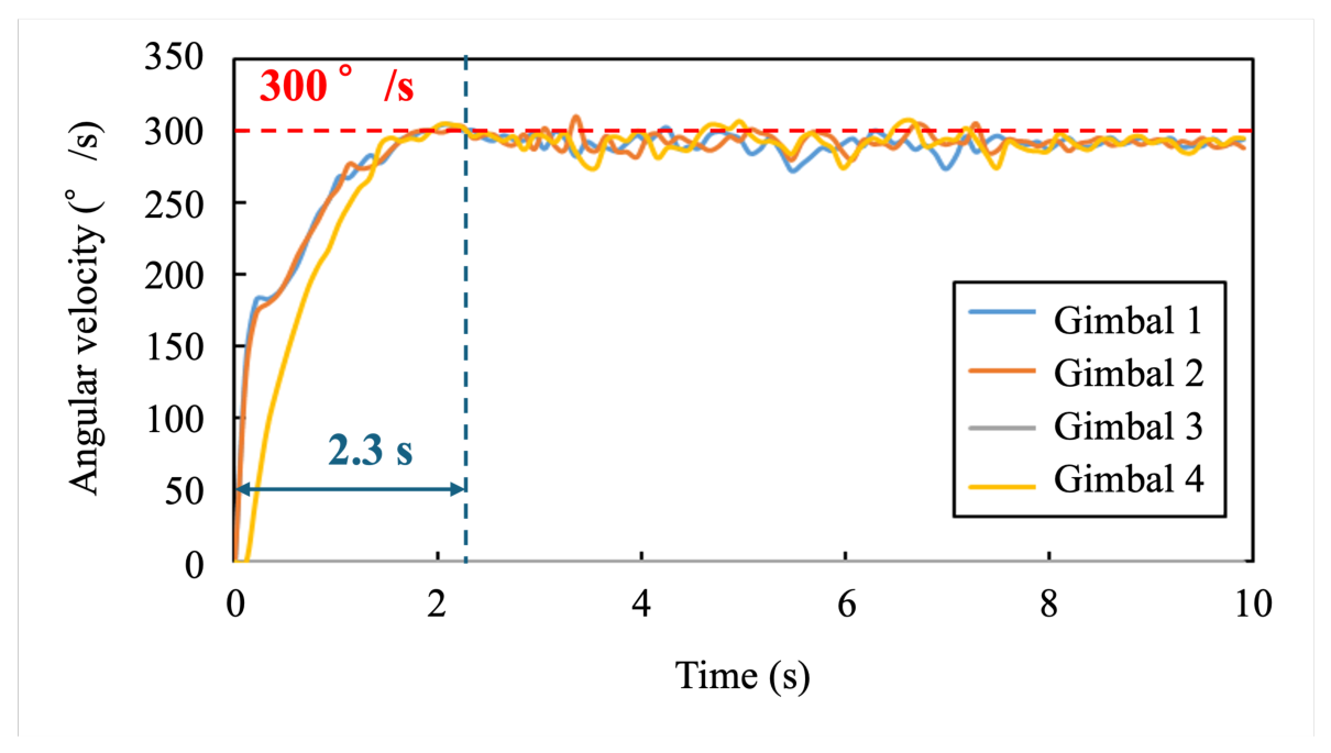
Figure A2 presents gimbal angular velocities for all four CMGs. All motors reached approximately 300 rad/s within about 2.3 s and maintained stable operation. The control cycle was 0.01 s. These results confirm that the actuator performance levels required for the proposed two-step CMG control strategy are achievable.
Figure A1.
Measured wheel rotational speed during ground testing. The wheel accelerates to approximately 10,000 rpm and is decelerated to around 5000 rpm.
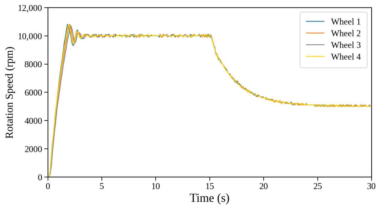
Figure A2.
Measured gimbal angular velocities during ground testing. All gimbals reached approximately 300 rad/s within about 2.3 s.
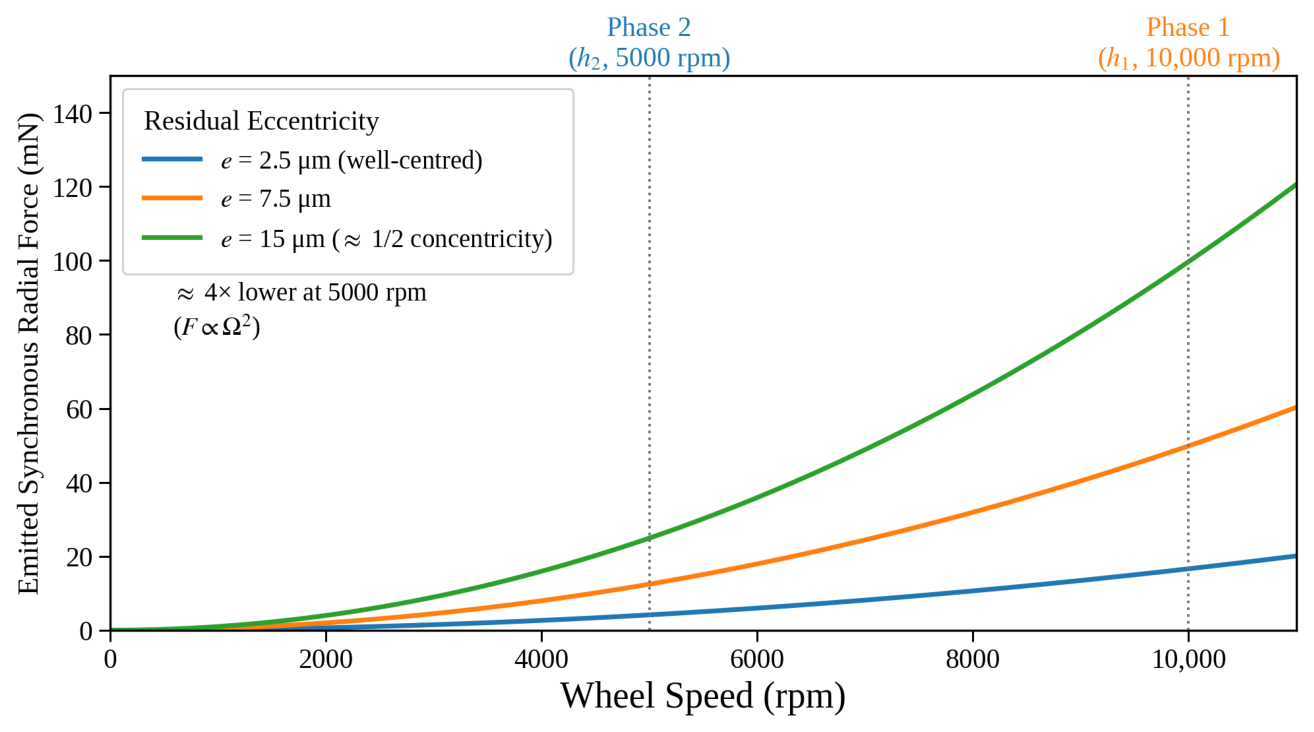
Because the proposed system targets precision pointing, wheel-induced micro-vibration warrants explicit treatment. The flywheel (C3602 free-cutting brass, mm × 2 mm, mass g, kg m2) was machined to a general tolerance of mm and an of , with the bore/seat features held to to mm and a mm runout/concentricity relative to the spin axis (drawing PXPS422A-T07). The rotor was not separately dynamically balanced, so its residual mass eccentricity e is bounded by this concentricity tolerance. The dominant emission is the synchronous radial force produced by the residual unbalance ,
which grows with the square of the wheel speed. Taking e in the – range consistent with the mm concentricity bound, the estimated emitted force is ≈16–99 mN at rpm (167 Hz) and ≈4–25 mN at 5000 rpm (83 Hz) (Figure A3). The flywheel is driven by a FAULHABER 1509T006B brushless DC motor on ball bearings (SUTB63A2ZZ), whose bearing-defect harmonics superpose on this synchronous component.
These COTS components are non-space-qualified and were used for ground feasibility testing only; the present figure is therefore an actuator-level estimate rather than an on-orbit jitter measurement. Nevertheless, because the two-step strategy operates the wheels at the lower momentum (≈5000 rpm) during the fine-pointing phase, it reduces this synchronous micro-vibration by a factor of about four ()—independently of the precise residual eccentricity—precisely when pointing stability matters most. Dynamic balancing of the rotor and a full forced-response/emitted-disturbance (jitter) characterization across the operating range, including bearing-induced and higher-harmonic components, are required for payload-level qualification and are identified as future work.
Figure A3.
Estimate of the residual-imbalance synchronous force versus wheel speed for residual eccentricities e bounded by the mm concentricity tolerance (no dynamic balancing), marking the two-step operating points; the scaling yields an ≈ reduction from Phase 1 ( rpm) to Phase 2 (5000 rpm).
References
- Heidt, H.; Puig-Suari, J.; Moore, A.S.; Nakasuka, S.; Twiggs, R.J. CubeSat: A new generation of picosatellite for education and industry low-cost space experimentation. In Proceedings of the 14th Annual AIAA/USU Conference on Small Satellites, Logan, UT, USA, 21–24 August 2000; p. ssc00-v-5. [Google Scholar]
- Sweeting, M.N. Modern small satellites—Changing the economics of space. Proc. IEEE 2018, 106, 343–361. [Google Scholar] [CrossRef] [Scilit]
- Roubal, C.; Dolejsky, T.; Rödiger, B.; Rein, F.; Rosano Nonay, J.; Rüddenklau, R.; Papadopoulos, C.; Schmidt, C.; Moll, F. Laser terminals on CubeSats: Developments for telecommunications and quantum links. Int. J. Satell. Commun. Netw. 2025, 43, 133–146. [Google Scholar] [CrossRef] [Scilit]
- Sannino, A.; Gaglio, E.; Mungiguerra, S.; Savino, R. Pitch stability considerations of 3U CubeSats for differential drag exploitation in vleo. Aerosp. Sci. Technol. 2026, 176, 112168. [Google Scholar] [CrossRef] [Scilit]
- Yang, X.; Liao, Y.; Li, L.; Li, Z. Agile attitude maneuver control of micro-satellites for multi-target observation based on piecewise power reaching law and variable-structure sliding mode control. Appl. Sci. 2024, 14, 797. [Google Scholar] [CrossRef] [Scilit]
- Li, J.; Post, M.; Wright, T.; Lee, R. Design of attitude control systems for CubeSat-class nanosatellite. J. Control Sci. Eng. 2013, 2013, 657182. [Google Scholar] [CrossRef] [Scilit]
- Mason, J.P.; Baumgart, M.; Rogler, B.; Downs, C.; Williams, M.; Woods, T.N.; Palo, S.; Chamberlin, P.C.; Solomon, S.; Jones, A.; et al. MinXSS-1 CubeSat on-orbit pointing and power performance: The first flight of the Blue Canyon Technologies XACT 3-axis attitude determination and control system. J. Small Satell. 2017, 6, 651–662. [Google Scholar] [CrossRef] [Scilit]
- Grøtte, M.E.; Gravdahl, J.T.; Johansen, T.A.; Larsen, J.A.; Vidal, E.M.; Surma, E. Spacecraft attitude and angular rate tracking using reaction wheels and magnetorquers. IFAC-PapersOnline 2020, 53, 14819–14826. [Google Scholar] [CrossRef] [Scilit]
- Espinoza Garcia, B.; Yanyachi, A.M.; Yanyachi, P.R. Non-linear control strategies for attitude maneuvers in a CubeSat with three reaction wheels. Int. J. Adv. Comput. Sci. Appl. 2020, 11, 728–737. [Google Scholar] [CrossRef] [Scilit]
- Yoo, H.E.; Kim, C.O.; Mok, S.H.; Yu, J.; Choi, K.H. An efficient design-to-verification framework for CubeSat ADCS: Application to INHA RoSAT. Aerospace 2026, 13, 189. [Google Scholar] [CrossRef] [Scilit]
- Schoolcraft, J.; Klesh, A.; Werne, T. MarCo: Interplanetary mission development on a CubeSat scale. In Space Operations: Contributions from the Global Community; Springer: Cham, Switzerland, 2017; pp. 221–231. [Google Scholar] [CrossRef] [Scilit]
- Kramer, A.; Bangert, P.; Schilling, K. UWE-4: First electric propulsion on a 1U CubeSat—In-orbit experiments and characterization. Aerospace 2020, 7, 98. [Google Scholar] [CrossRef] [Scilit]
- Bock, D.; Tajmar, M. Highly miniaturized FEEP propulsion system (NanoFEEP) for attitude and orbit control of CubeSats. Acta Astronaut. 2018, 144, 422–428. [Google Scholar] [CrossRef] [Scilit]
- Krejci, D.; Mier-Hicks, F.; Thomas, R.; Haag, T.; Lozano, P. Emission characteristics of passively fed electrospray microthrusters with propellant reservoirs. J. Spacecr. Rocket. 2017, 54, 447–458. [Google Scholar] [CrossRef] [Scilit]
- Heiberg, C.J.; Bailey, D.; Wie, B. Precision spacecraft pointing using single-gimbal control moment gyroscopes with disturbance. J. Guid. Control. Dyn. 2000, 23, 77–85. [Google Scholar] [CrossRef] [Scilit] [PubMed]
- Wie, B.; Bailey, D.; Heiberg, C. Singularity robust steering logic for redundant single-gimbal control moment gyros. J. Guid. Control. Dyn. 2001, 24, 865–872. [Google Scholar] [CrossRef] [Scilit] [PubMed]
- Wie, B. Space Vehicle Dynamics and Control, 2nd ed.; AIAA Education Series: Reston, VA, USA, 2008. [Google Scholar]
- Markley, F.L.; Crassidis, J.L. Fundamentals of Spacecraft Attitude Determination and Control; Space Technology Library; Springer: New York, NY, USA, 2014. [Google Scholar] [CrossRef] [Scilit]
- Jung, D.; Tsiotras, P. An experimental comparison of CMG steering control laws. In Proceedings of the AIAA/AAS Astrodynamics Specialist Conference, Providence, RI, USA, 16–19 August 2004; pp. 2004–5294. [Google Scholar] [CrossRef] [Scilit]
- Geshnizjani, R.; Fichter, W. Steering law for control moment gyroscopes with online torque capacity maximization. J. Guid. Control. Dyn. 2023, 46, 47–63. [Google Scholar] [CrossRef] [Scilit]
- Pereira, H.; Lourenço, P.; Batista, P. From singularity analysis to singularity avoidance: Novel metric and convex allocation for spacecraft attitude control with control moment gyros. Acta Astronaut. 2024, 225, 41–54. [Google Scholar] [CrossRef] [Scilit]
- Akiyama, K.; Fujihashi, K.; Matunaga, S. High-speed attitude control system for small satellite with micro-CMGs. Trans. Jpn. Soc. Aeronaut. Space Sci. Aerosp. Technol. Jpn. 2010, 8, 91–97. [Google Scholar] [CrossRef] [Scilit] [PubMed]
- Gaude, A.; Lappas, V. Design and structural analysis of a control moment gyroscope (CMG) actuator for cubesats. Aerospace 2020, 7, 55. [Google Scholar] [CrossRef] [Scilit]
- Papakonstantinou, C.; Lappas, V.; Kostopoulos, V. A gimballed control moment gyroscope cluster design for spacecraft attitude control. Aerospace 2021, 8, 273. [Google Scholar] [CrossRef] [Scilit]
- Papakonstantinou, C.; Moraitis, G.; Lappas, V.; Kostopoulos, V. Design of a low-cost air bearing testbed for nano cmg maneuvers. Aerospace 2022, 9, 95. [Google Scholar] [CrossRef] [Scilit]
- Yoon, H.; Tsiotras, P. Spacecraft adaptive attitude and power tracking with variable speed control moment gyroscopes. J. Guid. Control. Dyn. 2002, 25, 1081–1090. [Google Scholar] [CrossRef] [Scilit] [PubMed]
- Schaub, H.; Junkins, J.L. Analytical Mechanics of Space Systems, 4th ed.; AIAA Education Series: Reston, VA, USA, 2018. [Google Scholar] [CrossRef] [Scilit] [PubMed]
- Mcmahon, J.; Schaub, H. Simplified singularity avoidance using variable-speed control moment gyroscope null motion. J. Guid. Control. Dyn. 2009, 32, 1938–1943. [Google Scholar] [CrossRef] [Scilit]
- Higashiyama, D.; Shoji, Y.; Satoh, S.; Jikuya, I.; Yamada, K. Attitude control for spacecraft using pyramid-type variable-speed control moment gyros. Acta Astronaut. 2020, 173, 252–265. [Google Scholar] [CrossRef] [Scilit]
- Barman, S.; Sinha, M. Satellite attitude control using double-gimbal variable-speed control moment gyroscope: Single-loop control formulation. J. Guid. Control. Dyn. 2023, 46, 1314–1330. [Google Scholar] [CrossRef] [Scilit]
- Lyu, B.; Liu, C.; Yue, X.; Shi, L. Nonfragile super-twisting disturbance-observer-based inverse optimal control for spacecraft with integrated dynamics. IEEE Trans. Aerosp. Electron. Syst. 2026, 62, 6143–6152. [Google Scholar] [CrossRef] [Scilit]
- Ge, L.; Song, J.; Shen, Y.; Liu, C.; Fu, Q.; Song, S.; Xiao, D. Model predictive torque control of a novel multilevel power converter for four-phase SRMs. IEEE Trans. Ind. Electron. 2026, 73, 1596–1606. [Google Scholar] [CrossRef] [Scilit]
- Shi, K.; Liu, C.; Yue, X.; Shu, M. Spacecraft Electromagnetic Docking and Separation, 1st ed.; Elsevier: Amsterdam, The Netherlands, 2026; ISBN 978-0-443-49334-8. [Google Scholar]
- Wie, B.; Weiss, H.; Arapostathis, A. Quaternion feedback regulator for spacecraft eigenaxis rotations. J. Guid. Control. Dyn. 1989, 12, 375–380. [Google Scholar] [CrossRef] [Scilit] [PubMed]
- Ikeda, M.; Suda, N. Synthesis of optimal servosystems. Trans. Soc. Instrum. Control Eng. 1988, 24, 40–46. [Google Scholar] [CrossRef] [Scilit]
- Zhao, X.; Zheng, X.; Yu, J.; Qu, Y.; Xiao, J.; Pei, Y.; Zhang, L. Design and multi-level verification of micro-vibration suppression for high-resolution cubesat based on flywheel disturbance–optics–attitude control–structural integrated model. Aerospace 2025, 12, 1061. [Google Scholar] [CrossRef] [Scilit]
- Modenini, D.; Bahu, A.; Curzi, G.; Togni, A. A dynamic testbed for nanosatellites attitude verification. Aerospace 2020, 7, 31. [Google Scholar] [CrossRef] [Scilit]
- Ticona Coaquira, F.J.; Wang, X.; Vidaurre Torrez, K.W.; Mamani Quiroga, M.J.; Silva Plata, M.A.; Luna Verdueta, G.A.; Murillo Quispe, S.E.; Auza Banegas, G.J.; Antezana Lopez, F.P.; Rojas, A. Model-based design and testbed for CubeSat attitude determination and control system with magnetic actuation. Appl. Sci. 2024, 14, 6065. [Google Scholar] [CrossRef] [Scilit]
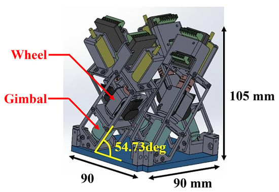
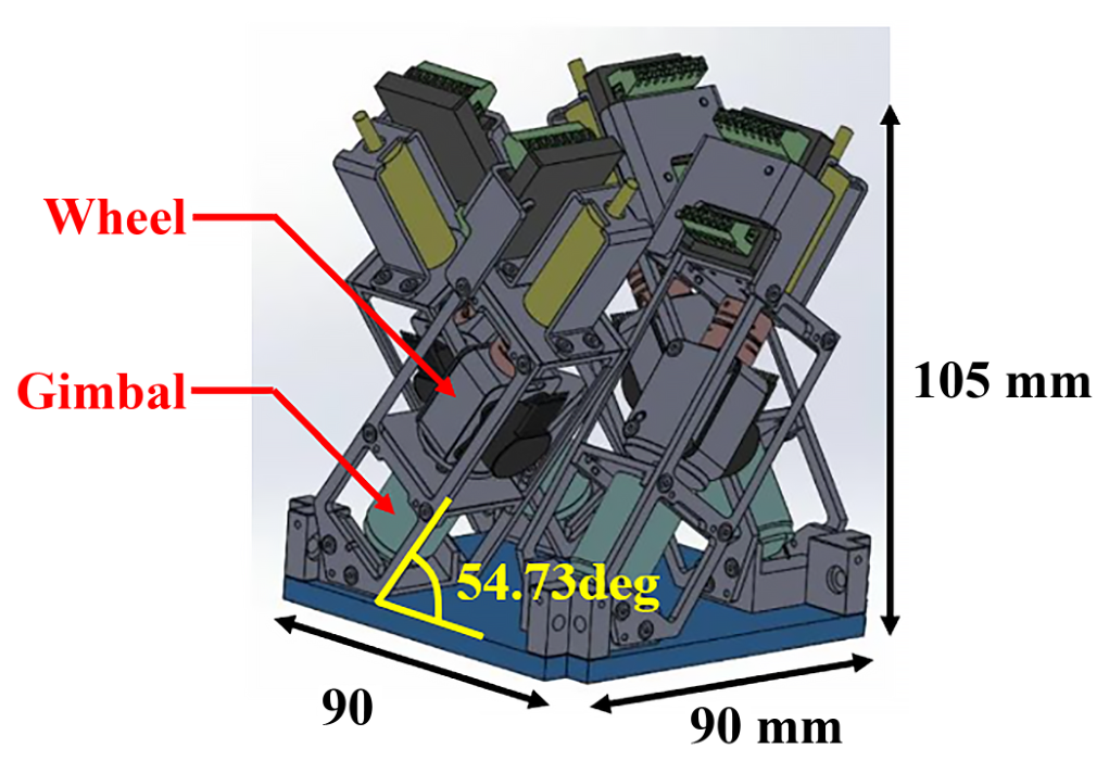
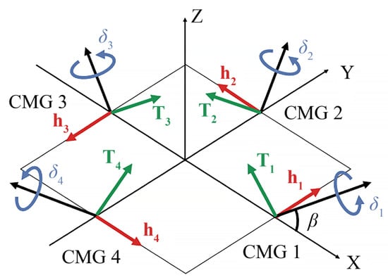
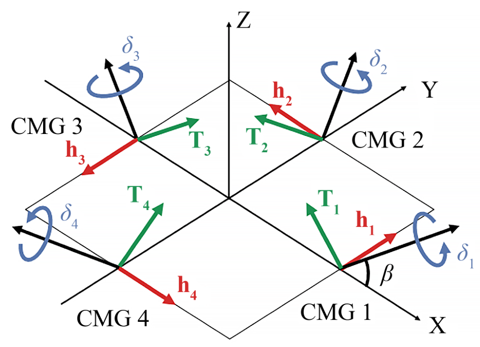
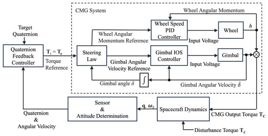
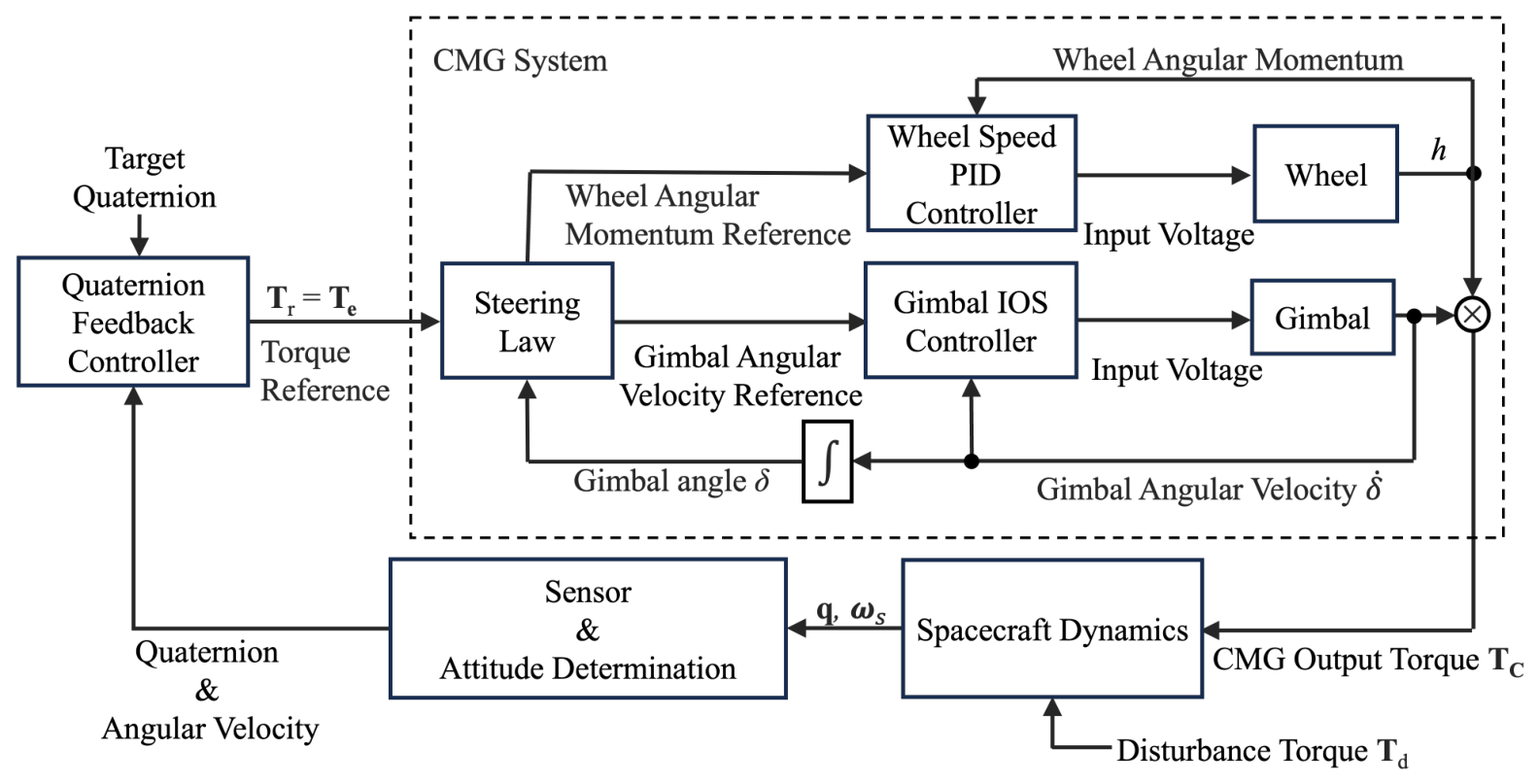
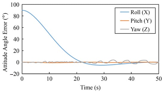
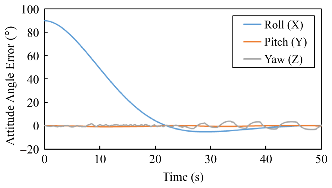
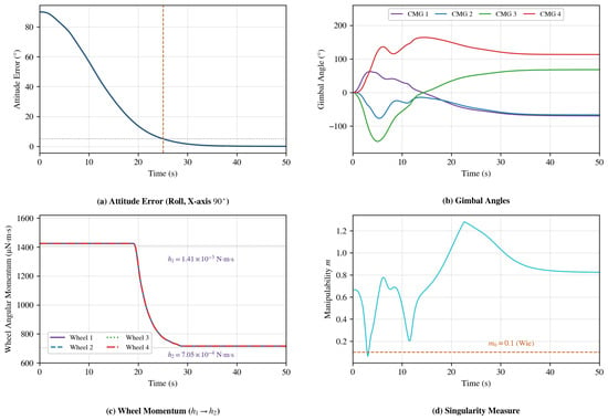
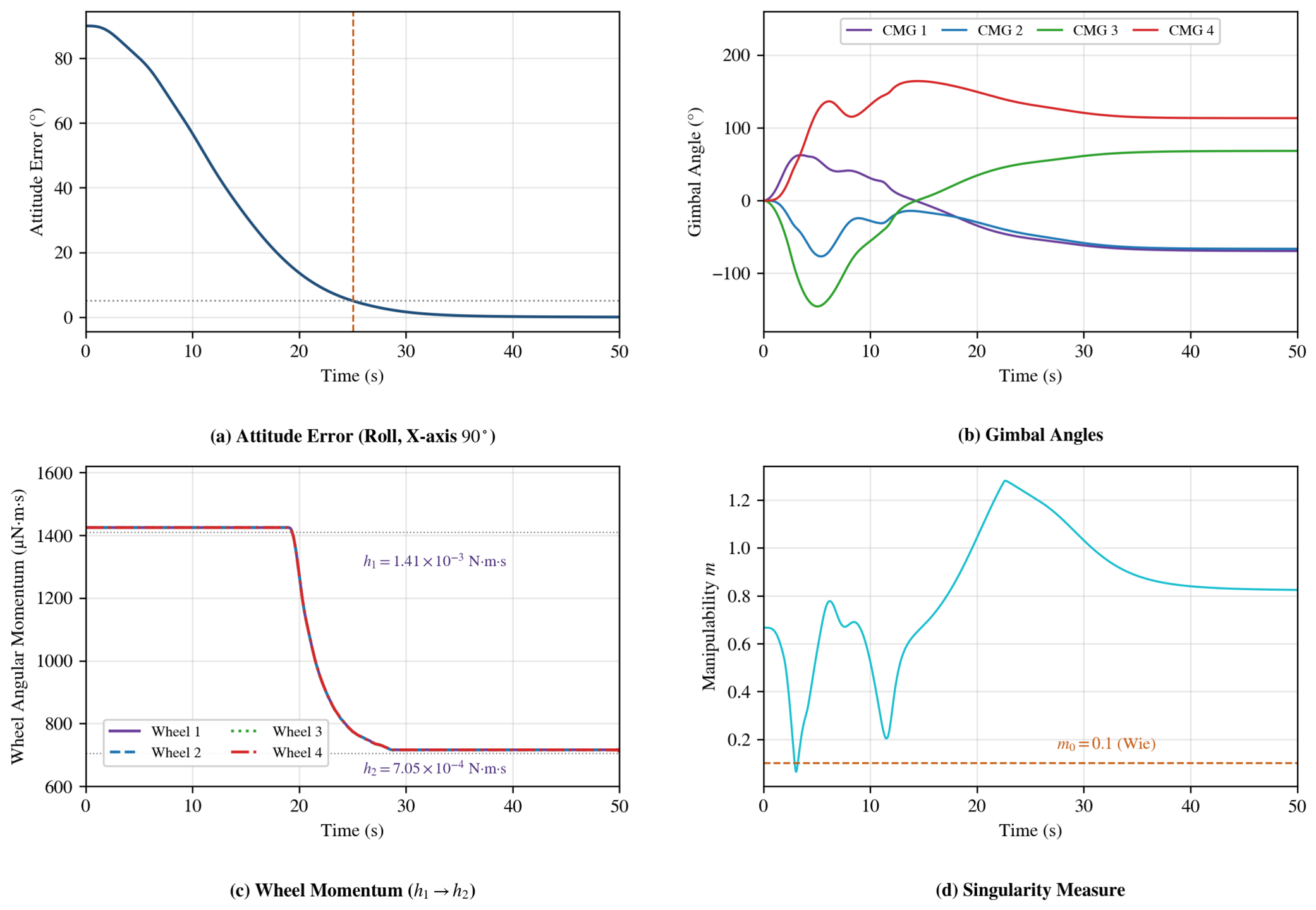
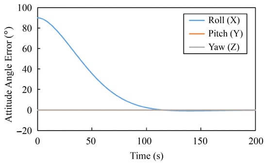
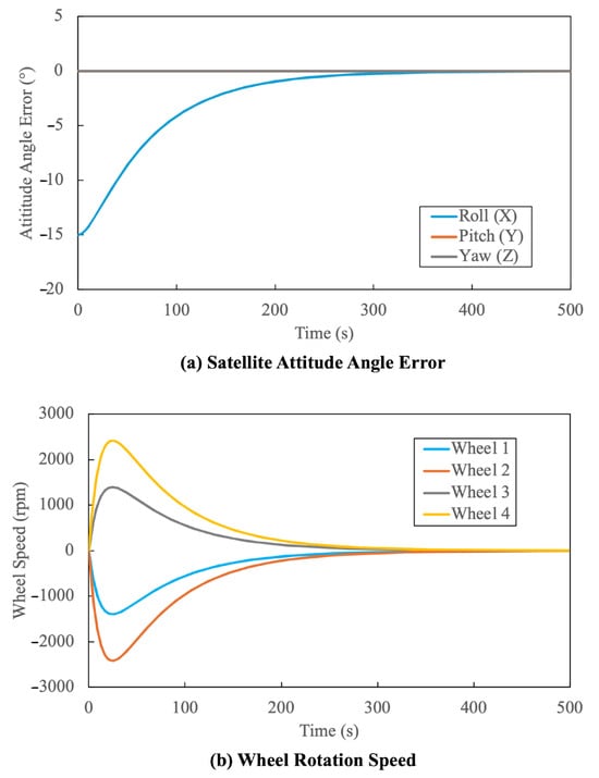
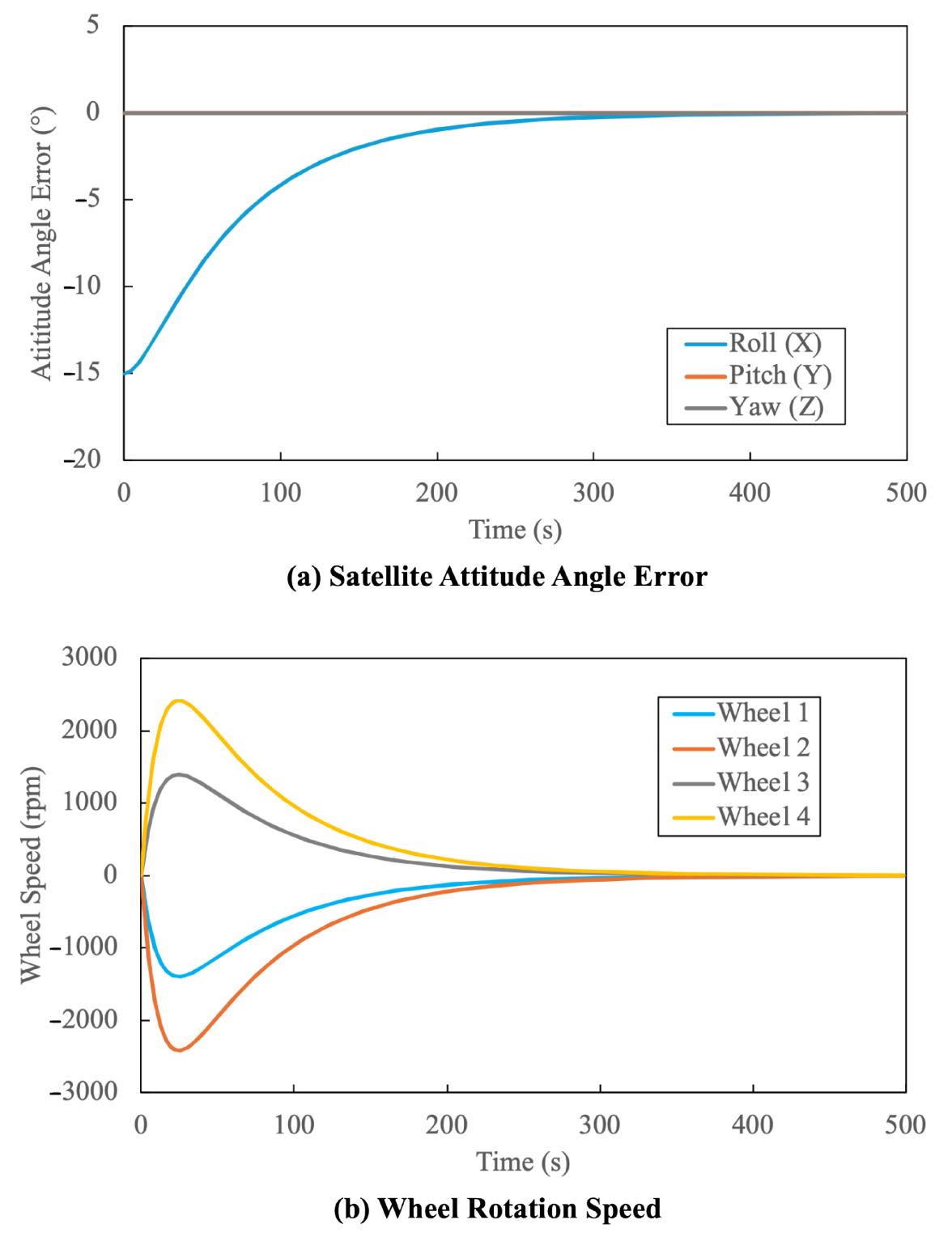
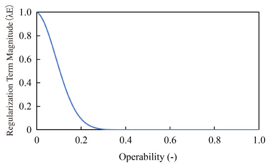
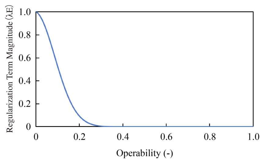
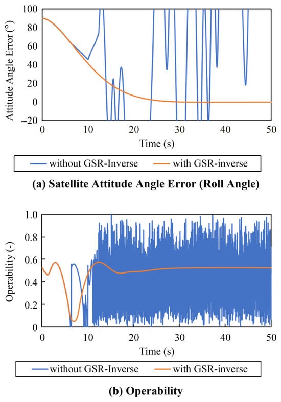
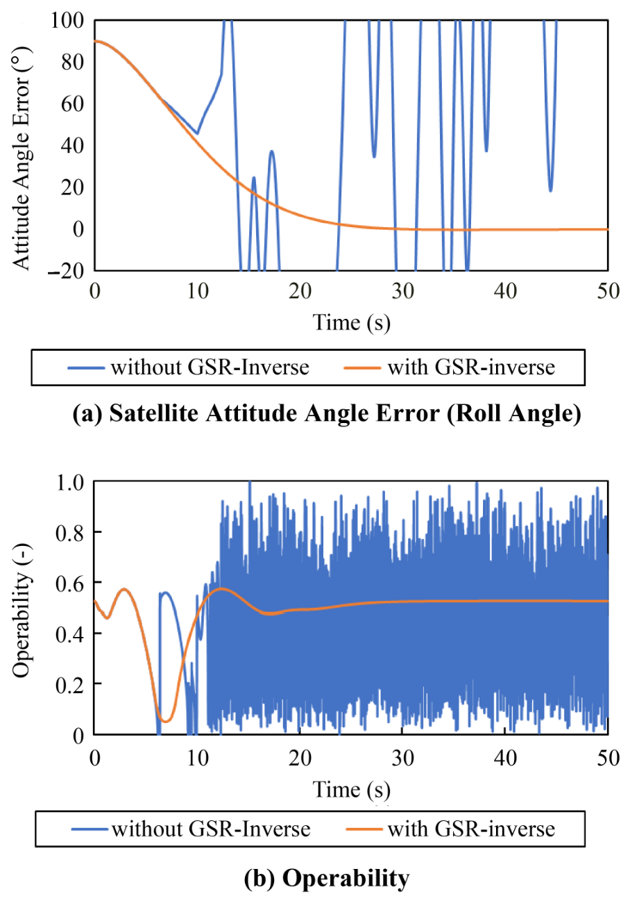
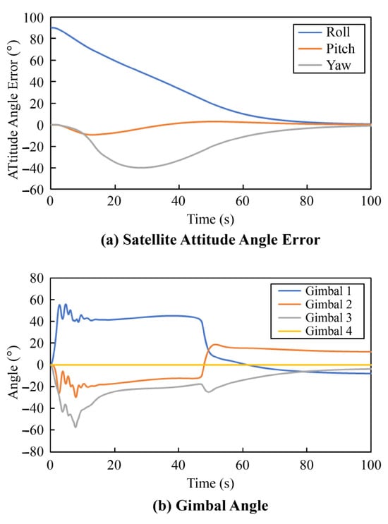
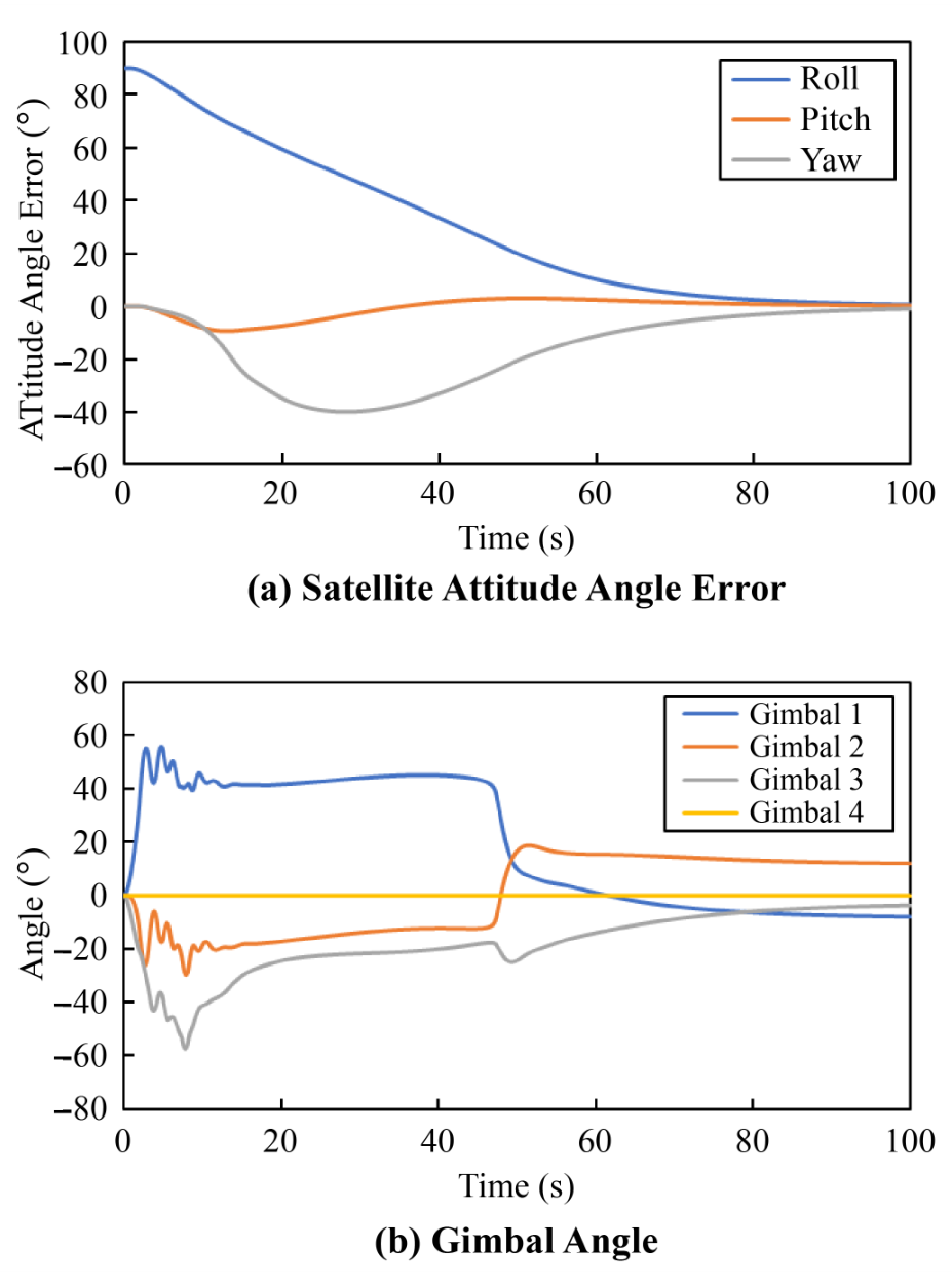
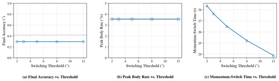
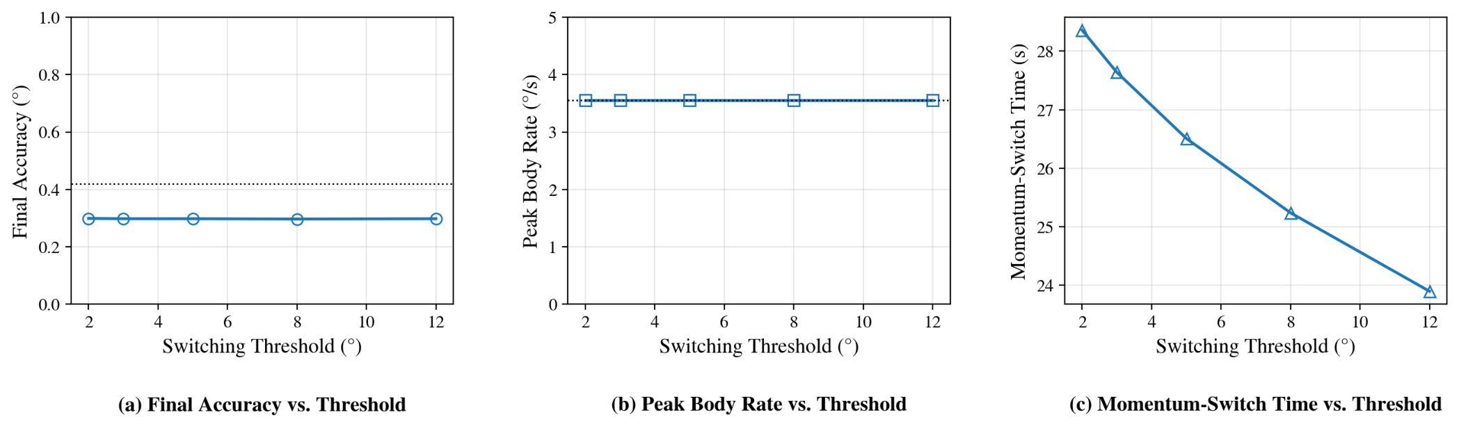
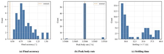
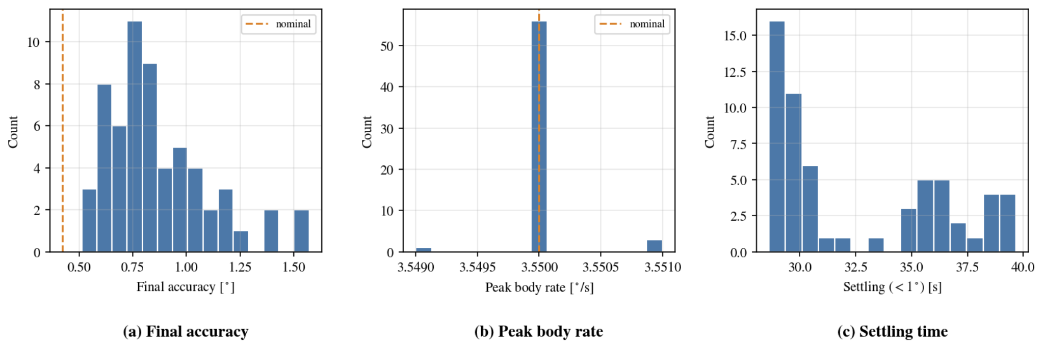
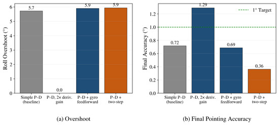
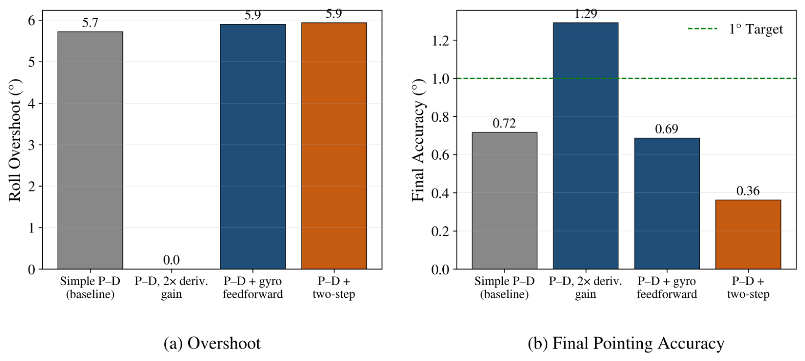

Disclaimer/Publisher’s Note: The statements, opinions and data contained in all publications are solely those of the individual author(s) and contributor(s) and not of MDPI and/or the editor(s). MDPI and/or the editor(s) disclaim responsibility for any injury to people or property resulting from any ideas, methods, instructions or products referred to in the content. |
© 2026 by the authors. Licensee MDPI, Basel, Switzerland. This article is an open access article distributed under the terms and conditions of the Creative Commons Attribution (CC BY) license.