


Abstract
Composite hat-stiffened panels are widely used in civil aircraft structural design as typical closed-section stiffened components with high load-carrying efficiency. To accurately predict the post-buckling bearing capacity and optimize the tapered termination design of such panels, this paper investigates the failure process of composite hat-stiffened panels with tapered ends through physical modeling and numerical analysis. A nonlinear failure analysis model is established by introducing the failure mechanisms of adhesive interfaces and composite laminates. The modeling method is verified against experimental results, showing discrepancies of 2.7% for buckling load and 3.5% for post-buckling failure load, respectively. Based on the validated numerical approach, parametric studies are carried out to analyze the effects of termination taper parameters on buckling and post-buckling mechanical behaviors. The results indicate that the termination taper design effectively adjusts the stiffness matching between stiffeners and skin and relieves local stress concentration. The optimal taper angle of 120° is recommended, where the failure load increases by 22% to 141.8 kN compared to the baseline configuration, significantly improving its post-buckling load-carrying capacity. The findings of this study can provide technical references for the design of stiffened composite panels with tapered stringer terminations in aerospace engineering.
1. Introduction
The invention of composite materials has opened new possibilities for weight control in aircraft design. Modeling of stiffened composite panels can begin with classical laminate theory [1,2]. Based on the Kirchhoff–Love assumptions [3], Mindlin et al. proposed and developed classical laminate theory [4,5,6], which, with the development of finite element methods, is now widely used in the analysis of stiffened composite panels. Research on stiffened composite panels has extensively explored how different combinations of composite panels and stiffeners enhance structural load-bearing capacity. Habib et al. [7] investigated the effects of stiffener spacing, cross-sectional shape, and composite layup distribution on buckling, finding that ultimate failure stresses show consistent trends across different layups. Kumar et al. [8] studied the influence of composite panel layup, aspect ratio, and stiffener geometry on buckling load, identifying the optimal layup angle to achieve the maximum critical buckling load. Li et al. [9] researched the fatigue and failure behavior of stiffened composite panels replacing traditional titanium alloy panels in thermal protection systems. In addition, in composite modeling methodology, Sha et al. [10] developed a three-dimensional Hashin criterion finite element analysis method for stiffened composite panels, enabling accurate failure prediction with reduced cost and time.
Stiffened composite panels, which maintain strong post-buckling load-carrying capacity even after initial buckling, are widely applied in aerospace structures [11,12,13,14]. In modern aircraft stiffened composite panel designs, hat-section stiffeners have attracted increasing attention from structural designers due to their excellent compressive stability characteristics; e.g., Filippatos et al. [15] have proposed an innovative design methodology including choosing a hat-stiffened panel as the typical aircraft component. However, owing to their large cross-sectional dimensions, hat-section stiffeners often exhibit initial local buckling modes at the stiffener flange. During the post-buckling stage, excessive deformation between the skin and stiffener may lead to interface delamination damage [16]. Moreover, in aircraft structural design, stiffeners are often terminated near critical locations such as wing ribs, fuselage frames, wing front/rear spars, or openings between wings and fuselages [17,18]. The interface at stiffener termination points is prone to adhesive debonding and delamination [19].
Research on the post-buckling behavior of composites mainly falls into two categories. One focuses on the post-buckling behavior characteristics of stiffened composite panels. Liu et al. [20] analyzed the compressive buckling and post-buckling behavior of large-scale stiffened composite panels with five hat-shaped stiffeners under filled and unfilled conditions, finding that the use of fillers improves structural load-bearing capacity. Chagraoui et al. [21] investigated the effects of a novel substructure configuration on the buckling and post-buckling performance of existing T-shaped stiffener composite panels. It is found that introducing ω-substrips in T-shaped stiffened composite panels redistributes concentrated stress zones, changes failure behavior, and affects the initiation and propagation of various failure modes. Huang et al. [22] studied the mechanism by which variable-stiffness design affects the buckling and failure behavior of T-shaped stiffened panels, identifying a significant increase in the load-carrying ratio of stiffeners as the main cause of strength reduction. Yu et al. [23] studied the post-buckling behavior of stiffened composite panels under combined shear and compression loading, finding that the failure load increases by 50% relative to the initial buckling load under combined loading. Yu et al. [24] conducted compression tests on stiffened panels with hybrid adhesive–bolt connections at stiffener ends, revealing that fracturing at truncated stiffener ends often leads to premature compression failure. Falzon et al. [25] investigated the post-buckling behavior of blade-shaped stiffener panels with tapered flanges, identifying interlaminar delamination at the midplane near the free-edge nodes of the stiffener web as the failure initiation site. Jiang et al. [26] proposed the influences of the fiber laying angle and graphene reinforcements of the composite trapezoidal wing plates, and it can be found that the combinations of fiber laying angles and width change should be carefully considered in the aircraft design.
The other research category focuses on optimizing stiffened panels by considering post-buckling behavior. Srilakshmi et al. [27] estimated optimal values for stiffener parameters and panel dimensions in stiffened composite panels based on the Hashin damage criterion. Zhang et al. [28] developed a finite-element nonlinear progressive damage model for stiffener composite panels, considering fiber–matrix failure, interfacial delamination, and stiffness degradation. They performed coupled analyses of load-carrying efficiency for stiffened panels with different cross-sectional dimensions but equal weight, identifying optimal design solutions.
Traditional designs use fasteners between the skin and flanges to mitigate crack propagation, but these methods only partially solve the problem and fail to suppress damage initiation. This is mainly due to insufficient stress alleviation and discontinuous stress distribution at termination points, which has promoted the widespread use of tapered stiffener terminations in structural design. Extensive research has been conducted on the post-buckling load-carrying behavior of tapered stiffener terminations in stiffened composite panels. Falzon et al. [29,30,31] experimentally and numerically investigated the effects of skin-thickening designs at stiffener terminations on structural load-carrying capacity, demonstrating that such designs mitigate stiffness transitions and enhance structural performance. Greenhalgh et al. [32] identified Mode II fracture as the dominant delamination mechanism at stiffener/skin interfaces through compression tests. Cosentino et al. [33,34] revealed that mixed Mode I/II fractures at adhesive interfaces under tensile loading are the main cause of delamination at termination points. Yu et al. [35] predicted the ultimate load capacity of curved hat-stiffened composite panels under axial compression, with results in good agreement with experimental data. Hou et al. [36] studied the failure mechanisms of three termination configurations under uniaxial tension/compression, finding that out-of-plane peel stresses and interlaminar shear stresses dominate tensile failure, while interlaminar shear stresses are critical for compressive failure. Xu et al. [37] revealed the influence mechanism of temperature changes and nonlinearity via an explicit equation, and it was seen that a deep learning-enabled explicit dynamics model could be employed for the studies of nonlinearity of composite structures.
This paper mainly presents the modeling process for hat-stiffened composite panels with tapered stiffener terminations. Through combined numerical and experimental analyses under compressive loading, failure mechanisms and optimized tapered designs are proposed to identify optimal taper parameters that maximize load-carrying capacity. This paper aims to provide technical guidance for the design of stiffened composite panels with tapered stiffener terminations in aerospace applications.
2. Structural Models
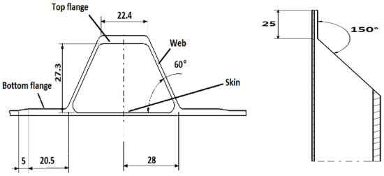
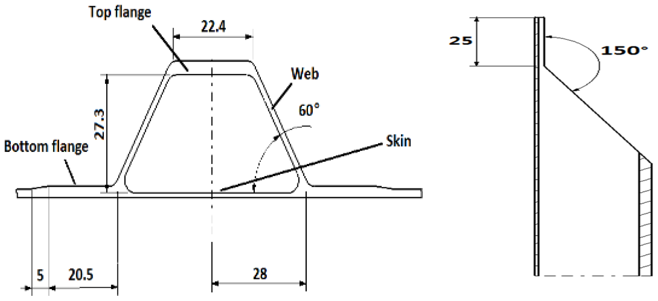
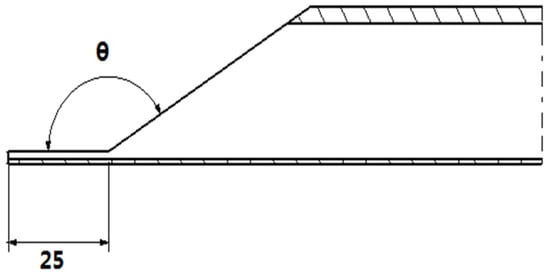
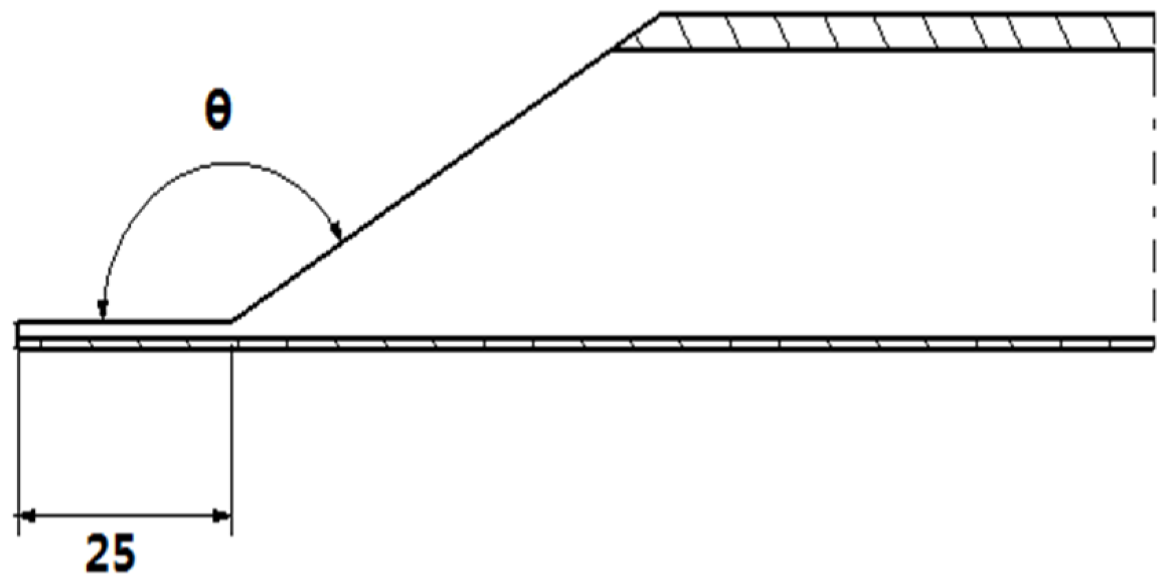
The composite hat-stiffened panel specimen in this study consists of three hat-shaped stiffeners and a skin. To meet the design requirements of large openings in aircraft wings, a tapered design is employed at the stiffener ends. The tapered region is located 25 mm from the end with a taper angle of 150°, as shown in Figure 1. The skin has a length of 630 mm and a width of 442.5 mm. The three hat-shaped stiffeners are evenly spaced at 157.5 mm. The layup information for each component of the stiffened panel structure is listed in Table 1. The panel is made of T700/BA9916 material (AVIC Composite Corporation Ltd., Beijing, China) with a ply thickness of 0.13 mm, and its mechanical properties are detailed in Table 2.
Figure 1.
Schematic of stiffener configuration in the stiffened panel.
Table 1.
Layup of components in the stiffened panel.
Table 2.
Engineering elastic constants and strength values of materials.
3. Numerical Modeling and Analysis
3.1. Mathematical Expressions
In the analysis of composite materials, classical laminate theory is typically employed. The relationship between the in-plane displacements u0, v0 and out-of-plane displacement w0 in the laminate and the displacements u, v, and w at any point can be described by the following simplified equations [38,39]:
where u, v, and w represent the displacement components at any point within the laminate; um, vm, and wm denote the displacement components on the midplane of the laminate; and z represents the distance from the point to the midplane.
The stress–strain relationship is determined by the constitutive relation of the material. For unidirectional laminated panels, the stress–strain relationship is:
where εx and εy represent the normal strains in the x and y directions on the midplane, respectively, while γxy denotes the shear strain on the midplane. κx and κy are the curvatures in the x and y directions, respectively.
In the equation, Aij, Bij, and Dij represent the tensile stiffness, in-plane bending coupling stiffness, and bending stiffness, respectively.
To introduce initial defects, the first-order mode of linear buckling is incorporated into the calculation of nonlinear buckling.
The governing equation of elastic stability analysis can be written as
where is the external force vector. is the geometric stiffness matrix, which is determined by stress and displacement, as shown in Equation (5).
Euler’s stability problem refers to a situation where any disturbance to the critical displacement of a system can cause it to lose stability when its initial stress state is in a critical state. The initial stress is , while the geometric stiffness matrix is ; then, Equation (4) can be written as:
Assuming that a critical state is reached at this point, there exists a perturbed displacement state that causes the system to remain in equilibrium even under constant external forces:
Then, the fundamental equation for linear buckling is as follows [40]:
K represents the structural stiffness matrix, Kσ represents the stress stiffness matrix, λi is the i-th eigenvalue, and φi is the i-th displacement eigenvector. The first-order mode of the linearly buckled structure is introduced as an initial imperfection into the nonlinear buckling analysis.
where K is the linear stiffness matrix and KNL is the nonlinear stiffness matrix.
On this basis, the quadratic strength criterion is employed to evaluate the initial damage at the bonding interface between the skin and the stiffening ribs, while the B-K criterion is adopted for damage propagation [39]. The quadratic strength criterion is:
where tn denotes the normal stress component; ts and tt denote the two shear stress components; t0n, t0s, and t0t represent the ultimate nominal stress values in the normal and shear directions, respectively.
The B-K criterion is as follows:
where GS = Gs + Gt, GT = Gn + GS, and Gn, Gs, and Gt represent the strain energy release rates under three crack propagation modes, respectively.
3.2. Numerical Modeling
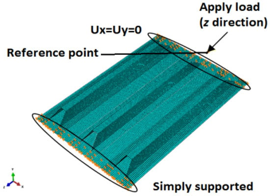
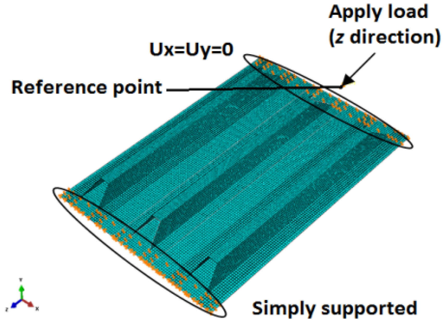
Based on the geometry of the structure in Figure 1, a finite element model consisting of three components is established. The element size is determined to ensure that each half-wavelength arising during the evolution of buckling modes and post-buckling responses contains at least 10 elements. To accurately simulate the buckling characteristics of the skin between hat-stiffener bottoms, the mesh size of both the skin and stiffeners is set to 5.0 mm × 5.0 mm according to the actual structural size, yielding 12 elements distributed over each span of the inter-hat skin. The skin and hat stiffeners were modeled via shell elements S4R, while the adhesive interface between the skin and stiffeners was simulated with 3D cohesive elements COH3D8 [41]. The cohesive elements were connected to the skin and stiffener shell elements to accurately simulate failure characteristics of the adhesive interface. Tie constraints are employed to enforce multipoint coupling and avoid material overlap. For load application and boundary conditions, simple support constraints were applied at the model support end, and the loading end was restrained with Ux = Uy = 0. A displacement load is imposed at the loading end through a reference point, with the loading direction aligned along the stiffener orientation (i.e., z-direction). The finite element modeling is presented in Figure 2.
Figure 2.
Finite element model and boundary conditions.
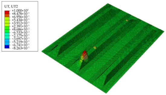
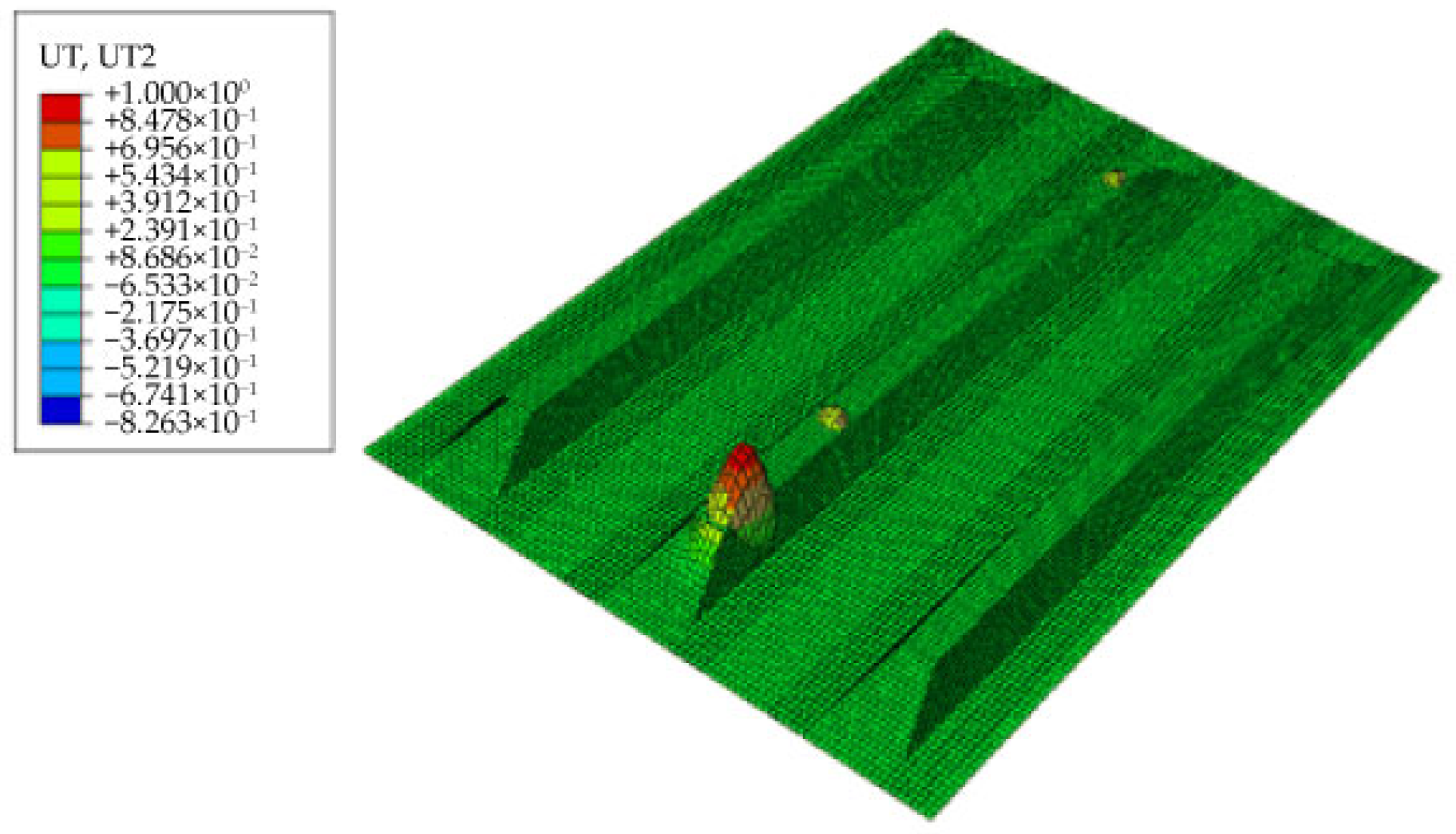
The buckling mode and buckling load of the structure were analyzed, as shown in Figure 3. The initial buckling mode of the stiffened composite panel structure is presented. The calculated buckling load was approximately 61.6 kN, characterized by a series of buckling half-waves forming on the skin beneath the central hat-stiffener, while no buckling occurred in other regions.
Figure 3.
Buckling mode of stiffened panel.
During the post-buckling analysis, the displacement obtained from the buckling analysis is introduced as an initial perturbation into the nonlinear model to account for damage [42]. The maximum disturbance amplitude is approximately 10% of the skin thickness, a value that can avoid severe convergence issues while not significantly altering the initial buckling behavior of the structure. The quadratic strength criterion is employed to assess initial damage in the adhesive interface elements between the skin and stiffeners, while the B-K criterion [38,39] is used for damage propagation. For in-plane fiber and matrix damage in the skin and stiffeners, the Hashin failure criterion [43] is applied for initial damage assessment, followed by material property degradation based on damage state variables.
3.3. Progressive Failure Analysis of the Structural Degradation Process
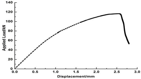
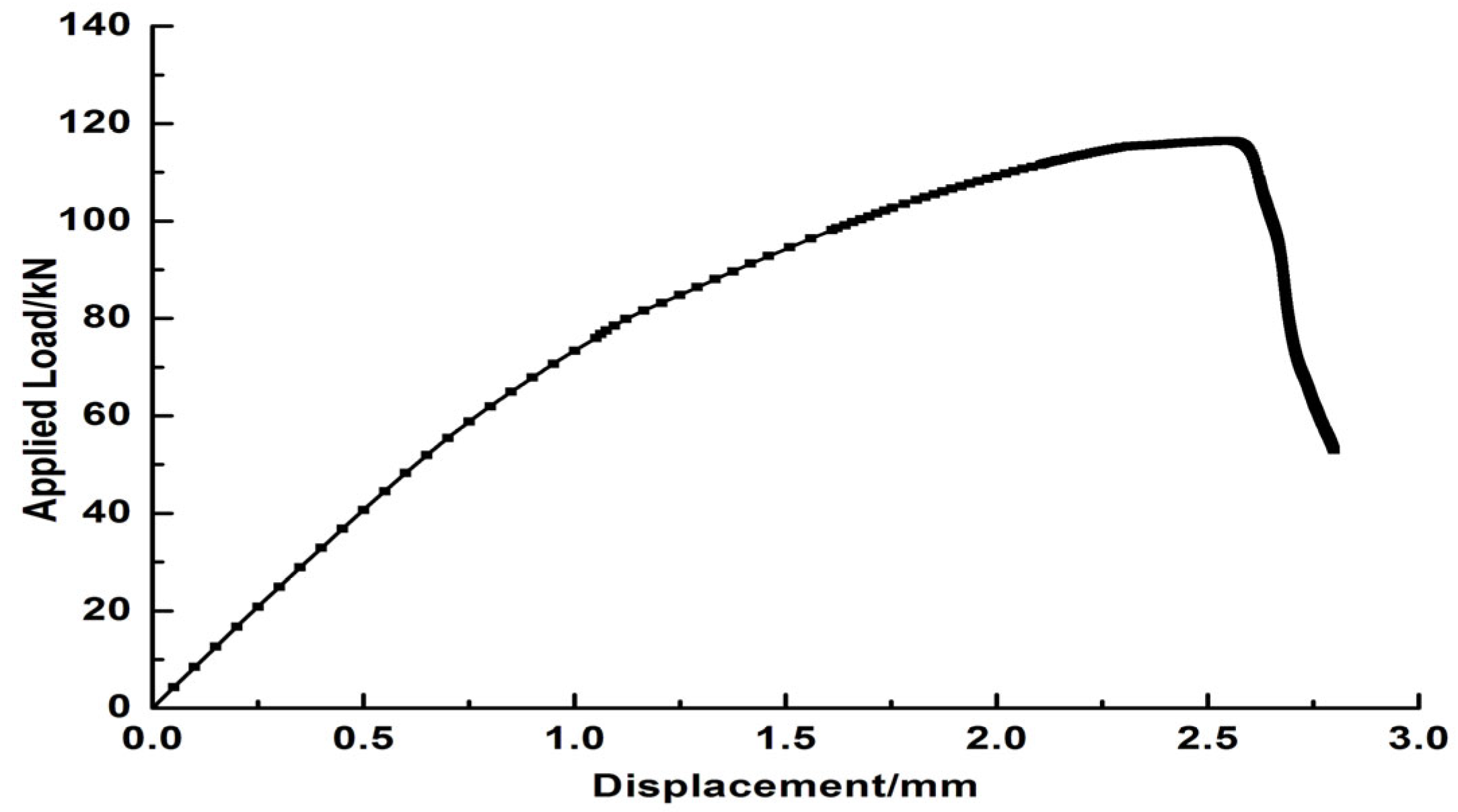
The displacement-load curves from the post-buckling analysis are shown in Figure 4. At the 1st inflection point of the curve, localized out-of-plane deformation occurred at the skin beneath the central stiffener’s cap, corresponding to a load of approximately 61.6 kN—consistent with the buckling load and mode from the linear buckling analysis. Beyond this point, the curve slope decreased, indicating reduced structural stiffness and the start of the post-buckling phase.
Figure 4.
Displacement–load curve at the loading point of the panel.
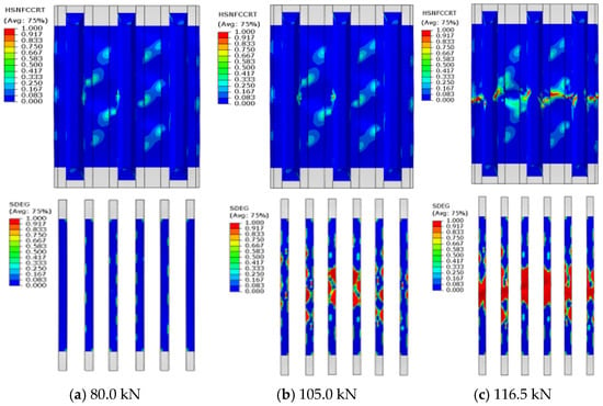
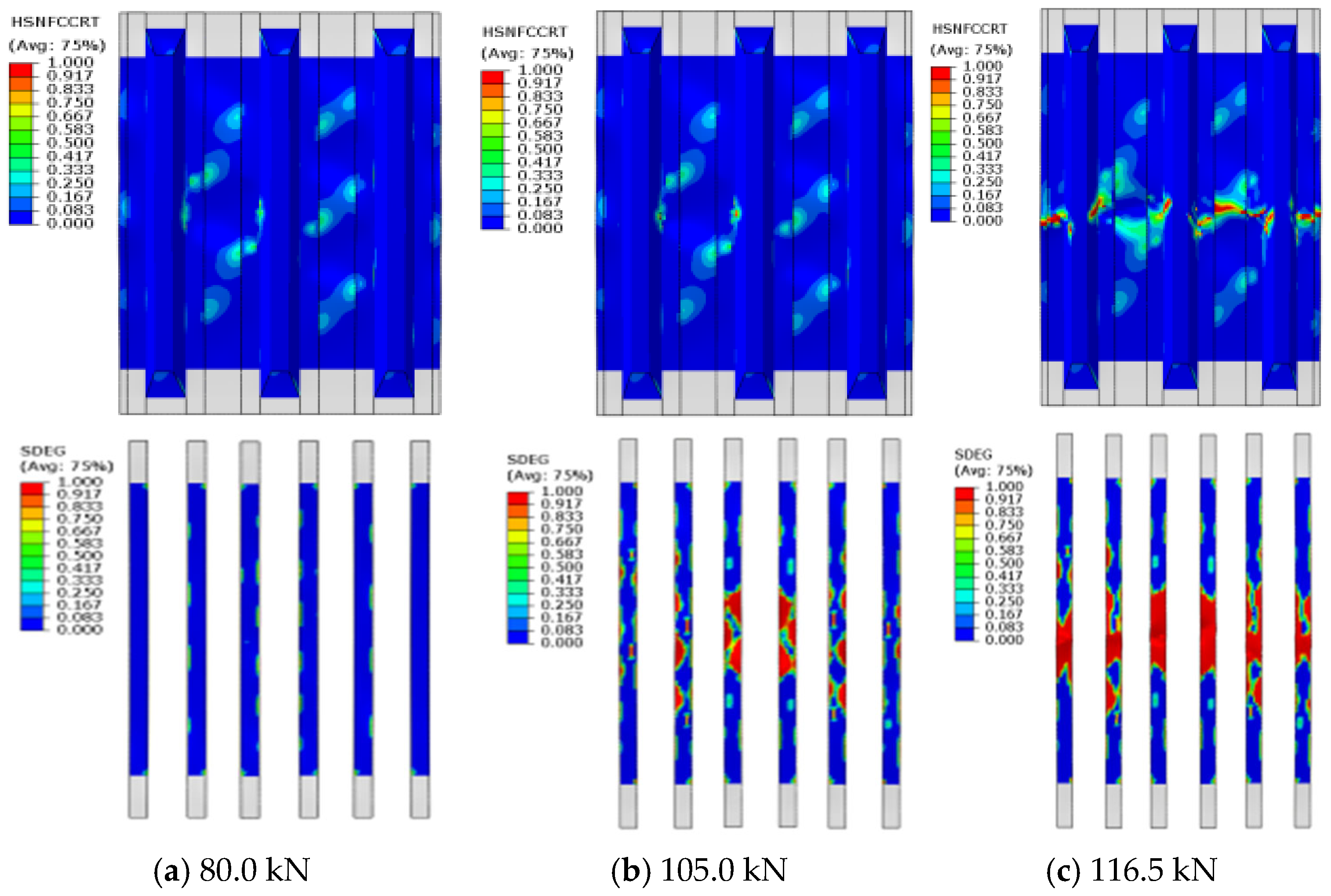
The damage evolution and failure process of the panel at different loading stages obtained from the finite-element analysis are presented in Figure 5. As the load increases beyond 80 kN, the curve slope continues to decline. Finite-element results show that delamination damage appears at the central adhesive interface between the stiffener and skin. With further loading, the delamination propagates rapidly in the lateral direction. At 105.0 kN, material failure occurs in the skin of this region due to stress concentration, causing in-plane fiber and matrix damage in the lower flange and web of the stiffener. This leads to a slight reduction in the global stiffness curve slope. Subsequently, interfacial delamination and material failure in the skin/stiffener composite accelerate. At 116.5 kN, through-thickness delamination and widespread in-plane material failure in the skin cause the central portion of the hat-stiffener to fracture, finally resulting in the loss of structural load-carrying capacity.
Figure 5.
Load–displacement curve for the loading point and failure process of the panel.
The structural failure mechanism can be summarized as follows: Buckling of the skin beneath the stiffener’s cap induces significant out-of-plane relative displacement between the lower flange and the skin, generating peel stresses at the adhesive interface. This initiates delamination in the interface region beneath the cap. As the load increases, the delamination propagates rapidly laterally, gradually weakening the stiffener’s support for the skin. Eventually, the interfacial delamination propagates across the transverse cross-section of three adjacent stiffeners, leading to stress concentration in the central skin region and triggering material damage. Subsequent failure mechanisms include rapid lateral expansion of the central skin damage zone, followed by damage to the midsection of the stiffener’s lower flange. Finally, the stiffener fractures at approximately 116.5 kN, leading to catastrophic failure of the panel.
4. Experimental Validation
4.1. Experimental Arrangement
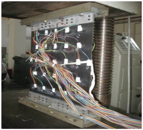
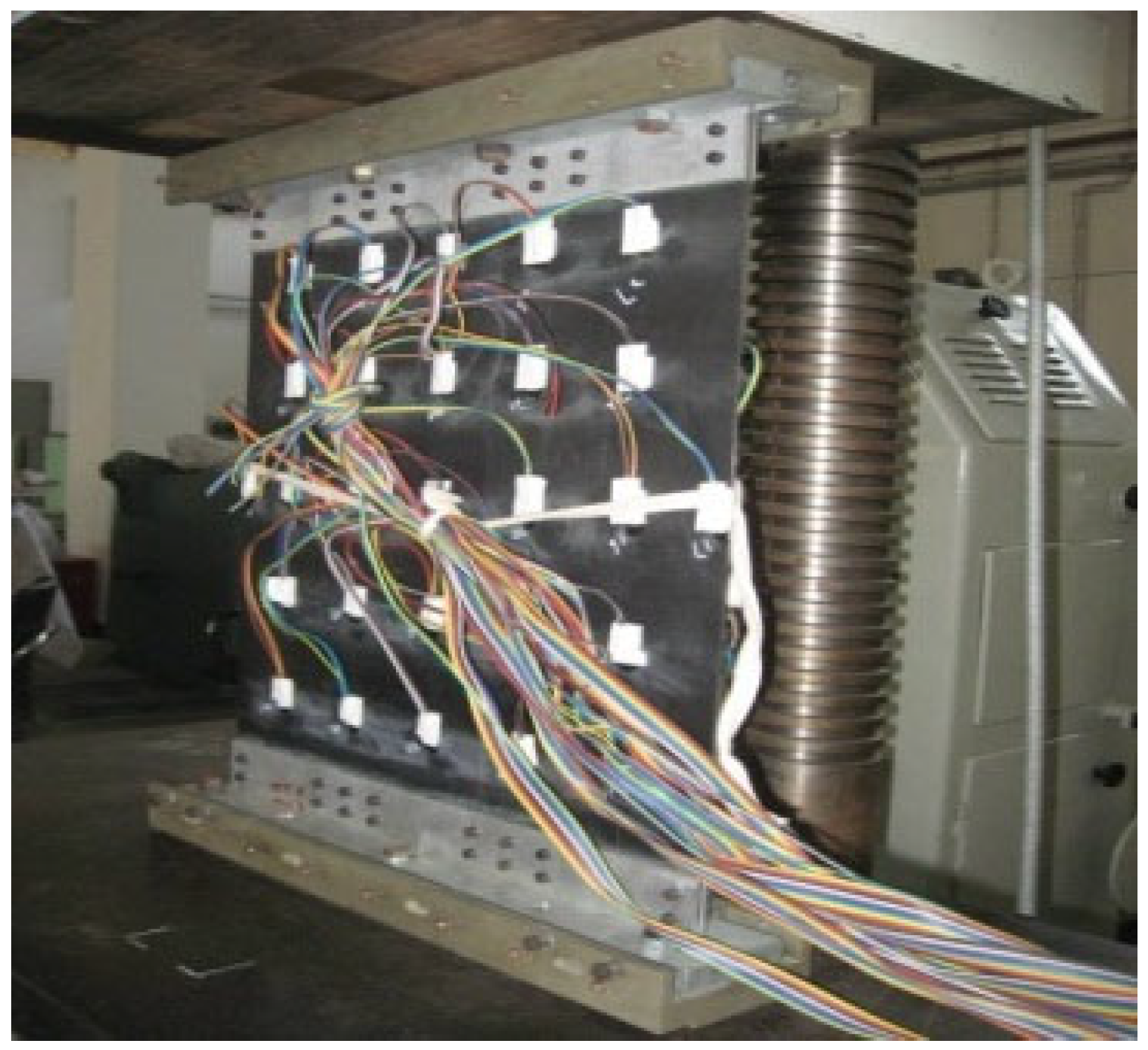
The composite hat-stiffened panels were tested on a YY200A pressure testing machine (ZwickRoell Materials Testing, Ulm, Germany), with the installation and support configuration shown in Figure 6. Reinforcement plates are installed at the loading and support ends of the panel, connected with high-lock bolts to prevent unexpected failures such as end crushing under compression. Additionally, specialized fixtures are used to simulate simply supported conditions, and the pressure center is adjusted. Preliminary experiments are conducted at low loads before proceeding with the formal experiments. During the experiment, the load was applied incrementally in steps of 2 kN up to 20 kN, after which the load was unloaded to inspect the integrity of the fixture, loading equipment, and measurement instruments. Subsequently, the load was incrementally increased in 2 kN steps to 50 kN, followed by gradual loading in 1 kN increments until structural failure occurred.
Figure 6.
Support and loading conditions of the panel specimen.
4.2. Experimental Results
During the incremental loading process, significant out-of-plane deformation occurred at the skin beneath the central stiffener’s cap when the load reached 60.0 kN, indicating localized buckling. Upon loading to 74.0 kN, a faint cracking sound was detected, and varying degrees of delamination were observed at the adhesive interface between the flange near the strain gauge and the skin. As the load continued to increase to 90.0 kN, obvious delamination and accompanying noise became evident. At 110.0 kN, continuous crisp sounds were audible during the experiment, with lateral delamination observed at the interface between the lower flanges of all three stiffeners and the skin, as well as localized delamination in the adjacent skin regions. At 113.0 kN, the specimen underwent continuous deformation and final failure.
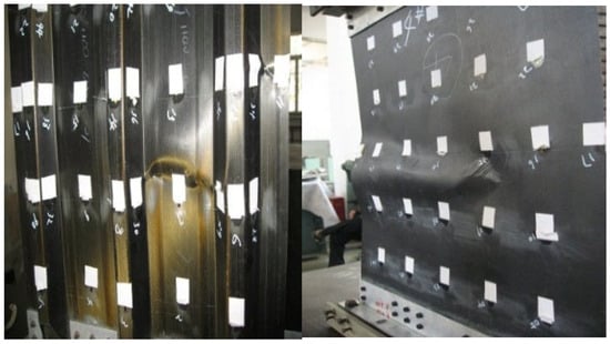
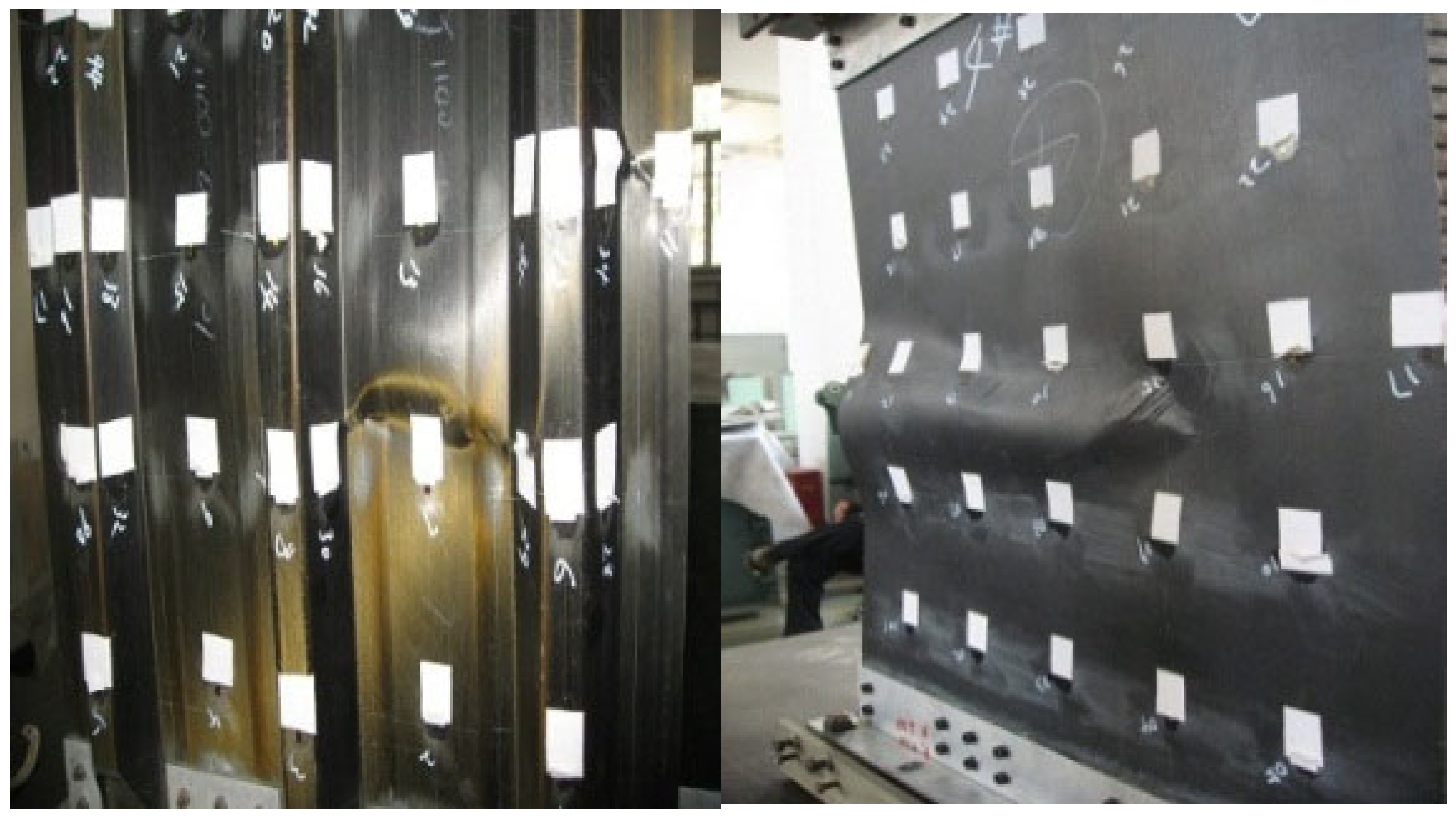
The photograph of the failed panel is shown in Figure 7. Delamination occurred at the interface between the three stiffeners and the skin in the central region, causing separation between the skin and stiffeners in this area. The stiffener fractured at its midpoint, and large-scale delamination was observed in the skin near the delaminated zone. Based on the experimental results, the failure mechanism can be preliminarily proposed: local buckling deformation at the hat-stiffener’s base under compressive loading causes interfacial delamination between the flange and skin. This weakens the stiffener’s support for the skin, leading to stress concentration in the central skin region and subsequent material failure, resulting in structural collapse.
Figure 7.
Failure of the panel model.
It can be seen from the comparison between the analysis and experimental results that the calculated buckling load was 61.6 kN and the failure load was 116.5 kN, while the experimental buckling occurred at 60.0 kN and failure was observed near 113 kN. The relative differences between analysis and experiment were 2.7% for the buckling load and 3.5% for the failure load. The analysis model exhibits approximately 4% deviation from the experimental results. Due to the use of experimental data from materials within the same batch, the influence of material property variability on the stiffness and strength of the panel is minimal; however, the discrepancy is primarily attributed to the differences between the idealized boundary conditions in the finite element model and the actual constraint states observed in the experiments.
The results indicate that the initiation and propagation of interfacial damage between the stiffener’s lower flange and skin are the direct causes of panel failure. Therefore, to improve the ultimate load-carrying capacity of the panel, design improvements can be made by optimizing the stiffness compatibility between stiffeners and skin to reduce stress concentration and conducting parametric studies on angled termination designs at stiffener ends to arrest delamination propagation and improve structural robustness.
5. Design Investigation
5.1. Comparative Analysis of Buckling and Failure Loads Under Different Bevel Angles
The baseline configuration of the stiffened panel structure from Section 2 was employed, with its typical geometric dimensions illustrated in Figure 8. During the bevel design, the reference point is defined as the outer surface of the lower flange of the hat-stiffened panel, located 25 mm from the end. The web and upper flange are then tapered at a specified angle relative to this reference, while the dimensions of the lower flange remain unchanged. Consequently, the lengths of the upper flange and web vary depending on the selected taper angle.
Figure 8.
Schematic of bevel dimension annotations.
To investigate the influence of termination bevel design parameters on the post-buckling load-carrying characteristics of composite hat-stiffened panels, the buckling and failure loads under different bevel design parameters are predicted. Specifically, the bevel angle at the stiffener terminations is selected as the variable parameter, starting from 90° and increasing by 15° to form a series of bevel design configurations. The corresponding buckling and failure loads for each stiffened panel configuration are calculated and summarized in Table 3.
Table 3.
Comparative study on buckling and post-buckling loads of structures with varying taper angles.
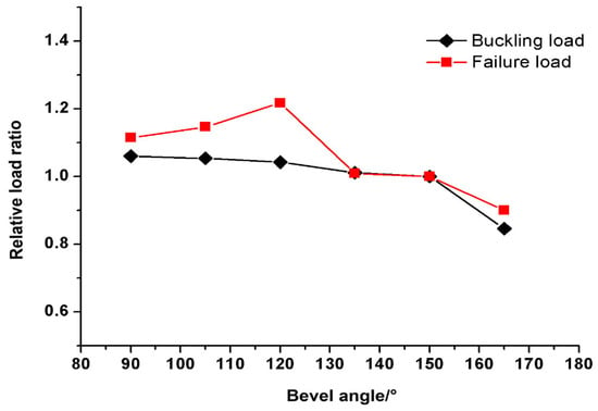
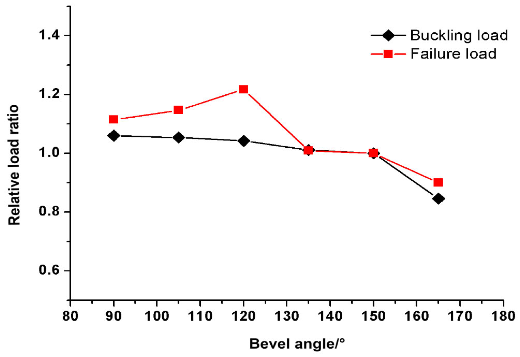
Using the buckling and failure loads of the stiffened composite panel with a bevel angle of 150° as the reference, normalization was performed. The resulting relative variation curves of buckling and failure loads, plotted against the bevel angle, are shown in Figure 9.
Figure 9.
Comparison curves of buckling and failure loads for panels with different bevel angles.
From the comparison in Table 3 and the curves, it can be seen that the maximum buckling load (65.3 kN) occurs at 90° (i.e., unbeveled termination). As the bevel angle varies from 90°, the buckling load initially changes slightly. However, after 105°, the post-buckling load decreases sharply. At 165°, the relative buckling load ratio drops to 0.85, reaching the minimum value of 52.1 kN. For failure load prediction: with increasing bevel angle, the relative failure load ratio gradually increases. At 120°, the ratio reaches 1.22, corresponding to a maximum failure load of 141.8 kN (a 22% increase compared to the reference). Beyond this angle, the relative failure load ratio decreases, dropping to 0.90 at 165°, with the failure load falling to 104.8 kN.
5.2. Post-Buckling Failure Mechanism of Termination-End Beveled Panels
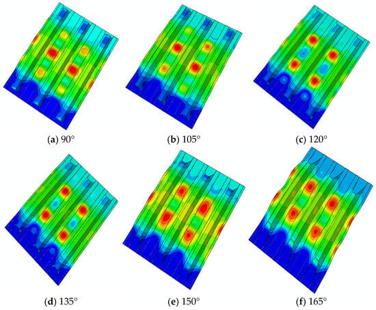
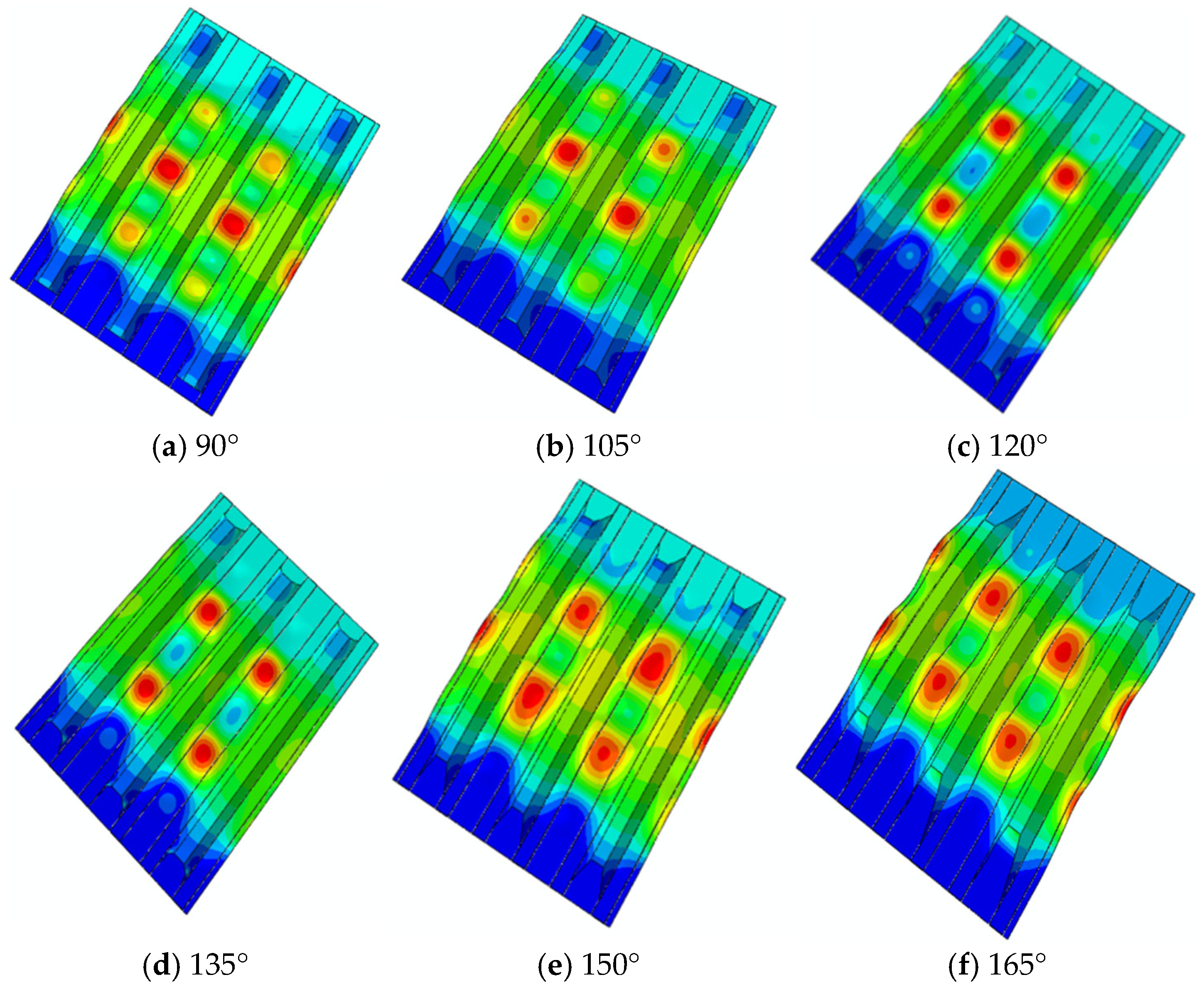
The post-buckling morphologies of stiffened panels at failure thresholds across different bevel angles are shown in Figure 10. For angles below 105°, the deformation pattern is similar to that of the unbeveled configuration (90°), with a wave crest forming at the panel midsection, and both buckling and failure loads remain comparable to the 90° reference case. However, as the bevel angle exceeds 120°, the mid-panel wave crest inverts to a trough while the failure mechanism remains consistent: delamination at the midsection interface between the skin and stiffener leads to material failure in both components, finally causing structural collapse. This transition in post-buckling morphology highlights the critical influence of bevel angles on both deformation patterns and failure behaviors, although interfacial delamination remains the dominant failure mode.
Figure 10.
Post-buckling morphology of stiffened panels at the failure threshold.
Further analysis of the reasons behind the variation in buckling and failure loads caused by bevel angles is conducted, considering the effects of bevel design on mitigating stress variations at the termination end and structural weakening of the stiffener. Buckling is primarily associated with structural stiffness characteristics. Since buckling consistently initiates at the skin beneath the hat-stiffener’s base, the structural weakening of the stiffener begins at a 90° bevel angle, slightly reducing its support for the skin. This leads to a gradual decrease in the buckling load. However, when the angle exceeds 150°, the stiffener’s structural weakening accelerates sharply, drastically diminishing its support capacity and causing a rapid decline in the critical buckling load.
For the predicted failure mode of the panel, the dominant mechanism remains interfacial delamination between the skin and stiffener caused by hat-stiffener base buckling. This leads to stress concentration at the panel’s midsection, causing the skin and stiffener materials to reach their failure strengths and eventually resulting in structural collapse. With increasing bevel angles, the stress mitigation effect within the stiffener gradually improves. When the angle reaches 120°, the stiffness ratio between the stiffener and skin achieves an optimal balance, resulting in minimal stress concentration in the stiffener and thus maximizing the failure load. Beyond this angle, further increases in the bevel angle exacerbate structural weakening and reduce the stress mitigation effect. This causes significant stress amplification within the stiffener, accelerating material failure of both components and leading to a rapid decline in the final structural load-carrying capacity.
It should be noted that the identified optimal taper angle is specific to the design space investigated in this study. While factors such as material system, layup configuration, adhesive behavior and manufacturing tolerances may influence the results, the sensitivity of the optimal taper angle to these parameters remains unclear, which introduces certain limitations to the present results.
6. Conclusions
This paper establishes a nonlinear progressive damage numerical model for composite hat-stiffened panels with tapered termination ends, combining finite element simulation and compression tests to reveal the post-buckling failure mechanism and optimize the termination bevel design. A concise modeling approach including the failure of composite laminates fibers and matrix and the debonding of bonding interfaces is proposed and it can also be employed for composite structure failure analysis. It reveals that stiffness-matching adjustment is the core mechanism to improve post-buckling bearing capacity in taper design. Structural stiffness and bearing characteristics under different taper angles are presented and discussed. The main conclusions are as follows:
- The proposed modeling approach integrating classical laminate theory, initial geometric imperfection introduction, quadratic strength criterion for interface initial damage, B-K criterion for delamination propagation, and Hashin criterion for laminate fiber/matrix failure. It can accurately predict the buckling and post-buckling ultimate load of composite hat-stiffened panels. The numerical results agree well with experimental data, with relative errors of only 2.7% for buckling load and 3.5% for failure load, verifying the effectiveness and reliability of the model.
- Under axial compression, the structural failure initiates from local buckling of the skin under the hat-stiffener, which induces out-of-plane relative displacement between the stiffener flange and skin, generates interface peeling stress, and triggers adhesive delamination. As the load increases, delamination rapidly expands laterally, weakening the stiffener’s support to the skin and causing severe stress concentration in the central skin area. Subsequently, laminate fiber and matrix failure occur successively, and finally the stiffener fractures, leading to overall structural collapse. Interfacial delamination initiation and propagation are the dominant failure modes governing the ultimate bearing capacity.
- The bevel design at the stiffener termination effectively adjusts the stiffness matching between the stiffener and skin, relieves termination stress concentration, and significantly improves the post-buckling bearing performance. Parametric analysis shows that the failure load first increases and then decreases with the increase in bevel angle, reaching the maximum at 120°, which is 21.72% higher than that of the original 150° design. The optimal bevel angle for termination is recommended as 120°, which can balance structural stiffness and stress relief to maximize the post-buckling load-carrying capacity.
The research results provide a feasible numerical analysis method and design basis for the post-buckling performance evaluation and tapered termination optimization of composite hat-stiffened panels in civil aircraft fuselage and wing structures, supporting the lightweight and high-efficiency design of aerospace stiffened composite structures. It is important to note that in modern civil aircraft stiffened panel design, in addition to the hat-stiffened configurations discussed in this study, I-section and T-section stiffeners are also widely adopted. Moreover, the stress states of these structures are not exclusively compressive. Therefore, this study only provides an engineering-applicable analytical method for such structural designs.
Author Contributions
Conceptualization, G.Z. and X.N.; methodology, G.Z. and L.C.; software, C.W.; validation, G.Z.; writing—review and editing, G.Z. and C.W. All authors have read and agreed to the published version of the manuscript.
Funding
This research received no external funding.
Institutional Review Board Statement
Not applicable.
Informed Consent Statement
Not applicable.
Data Availability Statement
The original contributions presented in this study are included in the article. Further inquiries can be directed to the corresponding author.
Conflicts of Interest
The authors declare no conflicts of interest.
References
- Stamatelos, D.G.; Labeas, G.N. Fast Buckling Analysis of Stiffened Composite Structures for Preliminary Aerospace Design. Aerospace 2010, 12, 726. [Google Scholar] [CrossRef] [Scilit]
- Xiang, Y.; Yin, Y.; Jing, X.; Li, X.; Jin, H.; Zhang, D. Buckling Strength and Sealing Performance of External Pressure-Resistant Stiffened Cylindrical Shell Structures with Split-Structure Characteristics. Aerospace 2025, 12, 1018. [Google Scholar] [CrossRef] [Scilit]
- Kirchhoff, G. Über das Gleichgewicht und die Bewegung einer elastischen Scheibe. J. Die Reine Angew. Math. (Crelles J.) 1850, 1850, 51–88. [Google Scholar]
- Mindlin, R.D. Influence of rotatory inertia and shear on flexural motions of isotropic, elastic plates. In The Collected Papers of Raymond D. Mindlin Volume I; Springer: Berlin/Heidelberg, Germany, 1989; pp. 225–232. [Google Scholar] [CrossRef] [Scilit]
- Whitney, J.M.; Leissa, A.W. Analysis of Heterogeneous Anisotropic Plates. J. Appl. Mech. 1969, 36, 261. [Google Scholar] [CrossRef] [Scilit]
- Reddy, J.N. A simple higher-order theory for laminated composite plates. J. Appl. Mech. 1984, 51, 745–752. [Google Scholar] [CrossRef] [Scilit]
- Habib, S.S.; Nahas, M.N. Failure of composite stiffened plates loaded in compression. J. Reinf. Plast. Compos. 1997, 16, 332–340. [Google Scholar] [CrossRef] [Scilit]
- Kumar, P.R.; Gupta, G.; Shamili, G.K.; Anitha, D. Linear buckling analysis and comparative study of un-stiffened and stiffened composite plate. Mater. Today Proc. 2018, 5, 6059–6071. [Google Scholar] [CrossRef] [Scilit]
- Li, H.; Yue, P.; Cheng, Y.; Zhuang, F.; Pei, C.; Cheng, X. Fatigue Performance of a Thermal Protection Structure with a Composite Stringer-Stiffened Panel. AIAA J. 2025. published online. [Google Scholar] [CrossRef] [Scilit]
- Sha, G.; Xiao, W.; Lu, X.; Zuo, H.; Cao, M.; Ostachowicz, W. Enhancing compressive failure prediction in repaired composites: A comparative study of 2D and 3D Hashin criteria with experimental validation. Thin-Walled Struct. 2025, 217, 113911. [Google Scholar] [CrossRef] [Scilit]
- Degenhardt, R.; Rolfes, R.; Zimmermann, R.; Rohwer, K. COCOMAT-improved material exploitation of composite airframe structures by accurate simulation of post-buckling and collapse. Compos. Struct. 2006, 73, 175–178. [Google Scholar] [CrossRef] [Scilit]
- Orifici, A.C.; de Zarate Alberdi, I.O.; Thomson, R.S.; Bayandor, J. Compression and post-buckling damage growth and collapse analysis of flat composite stiffened panels. Compos. Sci. Technol. 2008, 68, 3150–3160. [Google Scholar] [CrossRef] [Scilit]
- Orifici, A.C.; Tomson, R.S.; Dgenhardt, R. Degradation investigation in a post-buckling composite stiffened fuselage panel. In Proceedings of the 13th International Conference of Composite Structures, Melbourne, Australia, 14–16 November 2005. [Google Scholar]
- Bisagni, C.; Vescovini, R.; Dávila, C.G. Assessment of the Damage Tolerance of Postbuckled Hat-Stiffened Panels using Single-Stringer Specimens. In Proceedings of the 51st AIAA/ASME/ASCE/AHS/ASC Structures, Structural Dynamics, and Materials, Orlando, FL, USA, 12–15 April 2010; pp. 1–11. [Google Scholar]
- Filippatos, A.; Markatos, D.; Theochari, A.; Pantelakis, S. Integrating Sustainability in Aircraft Component Design: Towards a Transition from Eco-Driven to Sustainability-Driven Design. Aerospace 2025, 12, 140. [Google Scholar] [CrossRef] [Scilit]
- Chan, W.S.; Ochoa, O.O. Edge Delamination Resistance by a Crictical Ply Termination. Key Eng. Mater. 1989, 37, 285–304. [Google Scholar] [CrossRef] [Scilit]
- Yuan, F.; Cheng, L.; Chen, X.; Li, L.; Yu, F.; Chai, Y. Failure Analysis of Large-Scale Composite Fuselage Panels Under Combined Loads. Aerospace 2025, 12, 470. [Google Scholar] [CrossRef] [Scilit]
- Ren, A.; Zhang, T.; An, T.; Wang, Y.; Ma, L. Research on Residual Strength and Evaluation Methods of Aircraft Panel Structures with Perforations. Aerospace 2025, 12, 950. [Google Scholar] [CrossRef] [Scilit]
- Yang, Y.; Gong, M.; Xia, X.; Wu, L. Experimental and Numerical Study on Mechanical Properties of Z-pins Reinforced Composites Adhesively Bonded Single-Lap Joints. CMES-Comp. Model. Eng. 2022, 131, 365–378. [Google Scholar] [CrossRef] [Scilit]
- Liu, L.; Guan, Z. Influence of fillers on the post-buckling behavior of the hat-stiffened composite panels. Int. J. Aeronaut. Space Sci. 2023, 24, 1271–1282. [Google Scholar] [CrossRef] [Scilit]
- Chagraoui, H.; Lazghab, T.; Soula, M. Buckling optimization and post-buckling analysis of omega sub-stiffened composite panels using different cohesive interface properties. Thin-Walled Struct. 2023, 189, 110944. [Google Scholar] [CrossRef] [Scilit]
- Huang, Y.; Zhang, Y. Experimental and numerical studies on buckling and post-buckling behavior of T-stiffened variable stiffness panels. Chin. J. Aeronaut. 2024, 37, 459–470. [Google Scholar] [CrossRef] [Scilit]
- Yu, F.; Chen, L.; Chen, X.; Pang, B.; Yuan, F.; Li, L.; Wang, B. Experimental study on failure behaviour of stiffened composite panel under combined shear and compressive loading. J. Compos. Mater. 2025, 59, 2307–2320. [Google Scholar] [CrossRef] [Scilit]
- Yu, X.; Ren, F.; Yan, G.; Tang, J.; Cai, C.; Zhang, C.; Gu, X.; Xu, X. Compressive behavior of composite stiffened panels with hybrid bonded-bolted stiffener terminations: Experimental and numerical investigations. Thin-Walled Struct. 2025, 219, 114160. [Google Scholar] [CrossRef] [Scilit]
- Falzon, B.G.; Stevens, K.A.; Davies, G.O. Post-buckling behaviour of a blade-stiffened composite panel loaded in uniaxial compression. Compos. Part A Appl. Sci. Manuf. 2000, 31, 459–468. [Google Scholar] [CrossRef] [Scilit]
- Jiang, Y.; Wang, Y.; Wang, Y.H.; Yang, J.-H.; Qian, Y.-J. Experimental and theoretical investigations of fiber laying angle, graphene, and temperature effects on vibrational behaviors and nonlinear flutter in ternary graphene and carbon fiber reinforced composite trapezoidal wing plates. Eur. J. Mech.-A/Solids 2026, 116, 105918. [Google Scholar] [CrossRef] [Scilit]
- Srilakshmi, R.; Patil, S.; Lal, A. Investigation of the Effect of Stiffener Parameters on Post-Buckling Strength of Stiffened Composite Panels Using FEA; Lecture Notes in Mechanical Engineering; Springer: Berlin/Heidelberg, Germany, 2025; pp. 31–42. [Google Scholar] [CrossRef] [Scilit]
- Zhang, G.; Wan, C.; Nie, X. Post-buckling Behavior of Equal Weight Stiffened Composite Panels under Axial Compression. In Proceedings of the 2024 3rd International Symposium on Intelligent Unmanned Systems and Artificial Intelligence; Association for Computing Machinery: New York, NY, USA, 2024; pp. 379–384. [Google Scholar] [CrossRef] [Scilit]
- Falzon, B.J.; Davies, G.A.; Greenhalgh, E. Failure of thick-skinned stiffener run-out sections loaded in uniaxial compression. Compos. Struct. 2001, 53, 223–233. [Google Scholar] [CrossRef] [Scilit]
- Falzon, B.J.; Davies, G.A. The behavior of compressively loaded stiffener run-out specimens Part I: Experiments. J. Compos. Mater. 2003, 37, 381–400. [Google Scholar] [CrossRef] [Scilit]
- Falzon, B.J.; Davies, G.A. The behavior of compressively loaded stiffener run-out specimens Part II: Finite Element Analysis. J. Compos. Mater. 2003, 37, 481–501. [Google Scholar] [CrossRef] [Scilit]
- Greenhalgh, E.; Huertas, M. Fracture mechanics and failure processes at stiffener run-outs in polymer matrix. Compos. Part A 2004, 35, 1447–1458. [Google Scholar] [CrossRef] [Scilit]
- Cosentino, E.; Weaver, P.M. Approximate non-linear analysis method for debonding of skin/stringer composite assemblies. AIAA J. 2008, 46, 1144–1159. [Google Scholar] [CrossRef] [Scilit]
- Cosentino, E.; Weaver, P.M. Nonlinear analytical approach for preliminary sizing of discrete composite stringer terminations. AIAA J. 2009, 47, 606–617. [Google Scholar] [CrossRef] [Scilit]
- Mo, Y.; Ge, D.; Zhou, J. Experiment and analysis of hat-stringer-stiffened composite curved panels under axial compression. Compos. Struct. 2015, 123, 150–160. [Google Scholar] [CrossRef] [Scilit]
- Hou, R.; Xu, J.X.; Peng, F. Applying the Stressing State Theory and Network-Free Normalization Method Reveals the Failure Law of the Compression-Loaded Stiffened Composite Panels with Stiffener Runout. Polym. Compos. 2026, 47, 1912–1930. [Google Scholar] [CrossRef] [Scilit]
- Xu, D.; Zang, J.; Song, X.Y.; Zhang, Z.; Zhang, Y.-W.; Chen, L.-Q. Deep learning-enabled explicit dynamics model parameters for composite structures. Int. J. Mech. Sci. 2026, 316, 111472. [Google Scholar] [CrossRef] [Scilit]
- Benzeggagh, M.L.; Kenane, M. Measurement of mixed-mode delamination fracture toughness of unidirectional glass/epoxy composite with mixed-mode bending apparatus. Compos. Sci. Technol. 1996, 56, 439–449. [Google Scholar] [CrossRef] [Scilit]
- Turon, A.; Davila, C.G.; Camanho, P.P.; Costa, J. An engineering solution for mesh size effects in the simulation of delamination using cohesive zone models. Eng. Fract. Mech. 2007, 74, 1665–1682. [Google Scholar] [CrossRef] [Scilit]
- Gallagher, R.H.; Padlog, J.; Bijlaard, P.P. Stress analysis of heated complex shapes. ARS J. 1962, 32, 700–707. [Google Scholar] [CrossRef] [Scilit]
- ABAQUS/Standard User’s Manual, version 6.12; Hibbit; Karlsson and Sorensen Inc.: Pawtucket, RI, USA, 2012.
- Bertolini, J.; Castanié, B.; Barrau, J.; Navarro, J.-P. An experimental and numerical study on omega stringer debonding. Compos. Struct. 2008, 86, 233–242. [Google Scholar] [CrossRef] [Scilit]
- Hashin, Z. Failure criteria for unidirectional fiber composites. J. Appl. Mech. 1980, 47, 329–335. [Google Scholar] [CrossRef] [Scilit]

Disclaimer/Publisher’s Note: The statements, opinions and data contained in all publications are solely those of the individual author(s) and contributor(s) and not of MDPI and/or the editor(s). MDPI and/or the editor(s) disclaim responsibility for any injury to people or property resulting from any ideas, methods, instructions or products referred to in the content. |
© 2026 by the authors. Licensee MDPI, Basel, Switzerland. This article is an open access article distributed under the terms and conditions of the Creative Commons Attribution (CC BY) license.