


Abstract
Constructing rapid aerodynamic shape optimization frameworks based on high-fidelity reduced-order models (ROMs) has become a mainstream solution for alleviating the excessive computational cost of full-order simulation-based design, especially for complex configurations with high-dimensional design spaces. In this study, we propose the concept of transfer optimization, where a low-fidelity, decoupled auxiliary submodule is used to guide the high-fidelity optimization of the full complex system. Building upon our previously proposed reduced-order-model based framework for efficient aerodynamic shape design, a transfer optimization framework is further developed to improve the efficiency of aerodynamic shape design for complex multi-component configurations. A novel auxiliary submodule method is introduced to address the “curse of dimensionality” in sampling over high-dimensional design parameter spaces. By reducing system complexity, this method significantly lowers the cost of individual samples. Based on the transfer optimization assumption, perturbation-based sampling around the low-fidelity solution overcomes the limitations of traditional data augmentation approaches. Moreover, the auxiliary submodule optimization results are used to construct a physically meaningful initial configuration, further accelerating convergence. The framework is validated on two transonic aerodynamic optimization test cases using the three-dimensional undeflected Common Research Model (uCRM) wing–body–tail configuration (with a wing aspect ratio of 9), with and without horizontal tail deflection. Results show that the proposed framework achieves accuracy comparable to full-order optimization while reducing computational cost by up to 69.8%. Compared to traditional ROM-based frameworks, efficiency is further improved by 18.5% and 24.1% in Case 1 and Case 2, respectively.
1. Introduction
Aerodynamic shape optimization design through numerical simulations is widely used in the aerospace domain, and it plays a significant role in improving aircraft performance and reducing fuel consumption. The shapes of modern aircraft are becoming increasingly complex, with performance requirements rising and design conditions becoming more demanding. The emergence of integrated design requirements has made the immense computational cost associated with traditional full-order aerodynamic shape optimization design based on Computational Fluid Dynamics (CFD) simulations unacceptable. The mainstream approach to addressing this dilemma is to accelerate aerodynamic design through high-fidelity nonlinear ROMs [1,2,3,4,5]. In recent years, the rapid development of intelligent algorithms has driven significant advancements in data-driven, non-intrusive high-fidelity ROMs [6,7,8,9]. When these models are applied to aerodynamic shape optimization design to enhance optimization efficiency, constructing the sampling space faces substantial challenges, particularly when the design space has a very high dimension, a phenomenon known as the “curse of dimensionality” [10]. Therefore, researchers have proposed the concept of design space dimensionality reduction based on the assumption that high-dimensional design spaces depend on low-dimensional embeddings. Representative methods include active subspace (AS) method, active manifold (AM) method [10,11,12], and others. Boncoraglio and Farhat [10], drawing on Active Manifold theory, proposed that a multi-layer auto-en/decoder constructed using deep neural networks is capable of identifying low-dimensional nonlinear manifold embeddings within a high-dimensional design parameter space. In this way, the optimization process can be transferred to a low-dimensional space, thereby effectively alleviating the “curse of dimensionality.” However, a high-accuracy multi-layer active manifold auto-en/decoder requires a sufficiently rich sample space for training, which makes the sampling strategy for the sample space critically important. To this end, Boncoraglio and Farhat [10] proposed the “auxiliary problem” sampling strategy, which has since become a mainstream solution for this class of problems. This auxiliary optimization problem is derived by simplifying the original problem, such as by removing certain constraints. The solution process and initial values remain the same as those used in the original problem. The full-order optimization path is recorded, and the sample set is expanded by applying small perturbations to the recorded samples. Nevertheless, the present study shows that, particularly for complex multi-component configurations, the auxiliary problem approach exhibits several limitations:
- Ambiguity in the construction strategy for auxiliary problems. There is a lack of clear guidance regarding how auxiliary subproblems should be simplified and constructed. Complex original optimization problems often involve a large number of linear and nonlinear constraints, and the relationships among different constraint terms, their sensitivities with respect to the objective function, and the associated growth in computational cost are difficult to determine through qualitative analysis alone. Consequently, multiple simplification schemes may be available. Clearly, random selection is unlikely to achieve the desired construction objective, and may even lead to extreme situations in which the auxiliary problem becomes more difficult to solve than the original problem, or in which the optimized solution of the auxiliary problem deviates significantly from that of the original problem. If sensitivity analysis of the constraints with respect to the objective function is performed in order to avoid such blind construction, additional computational cost is inevitably incurred. Moreover, the analysis results are strongly dependent on the specific model and operating conditions, and therefore lack general applicability.
- High computational cost in solving auxiliary problems. In essence, solving an auxiliary problem still requires a full-order CFD simulation of the original system. In iterative aerodynamic shape optimization, the most computationally expensive component of each iteration is precisely the CFD simulation and adjoint equation solution. The dominant factor affecting this computational burden is the complexity of the system itself; accordingly, the time cost per iteration is scarcely reduced. The auxiliary problem approach is effective for optimization problems involving small- and medium-scale systems. However, when applied to large-scale optimization problems for complex multi-component aircraft configurations, the ambiguity in the construction strategy of auxiliary problems may easily introduce substantial additional computational expense. Therefore, the auxiliary-problem-based sampling strategy is not well suited to the design of large-scale complex systems.
- Limited means of initial sample space augmentation. The auxiliary problem sampling strategy enhances the initial sample space by superimposing prescribed noise on the initial samples. Under such an augmentation scheme, the multi-layer active manifold auto-en/decoder is passively trained as a noise filter. According to the underlying principle of the auxiliary problem approach, the number of additional samples is subject to an upper limit. The simple superposition of noise is therefore not an optimal augmentation strategy. Accordingly, a new sampling strategy is required, one that can introduce a greater number of high-quality sample points under the guidance of a more systematic theory of sample space augmentation.
To address the limitations of the auxiliary-problem-based [10] sampling strategy in applications involving complex multi-component configurations, this study introduces the concept of transfer optimization, whereby low-fidelity auxiliary submodules, decoupled from the complex system, are employed to support the high-fidelity rapid optimization of the full system; the core of this framework lies in the auxiliary submodule sampling strategy. Although model systems have become increasingly complex in practical applications, optimization efforts are often concentrated on key submodules, such as the wing and tailplane, that exert a substantial influence on the aerodynamic performance of the overall system. Accordingly, the aerodynamic transfer optimization framework incorporates a new “auxiliary submodule” sampling strategy. Unlike the auxiliary problem method, the auxiliary submodule sampling strategy does not alter the optimization problem itself. Instead, it isolates the core submodules, significantly reducing the model complexity, and uses low-precision simplified submodules to drive high-precision system optimization. It should be noted that auxiliary submodule sampling is performed for the training of the auto-coder, whereas the sampling process used for ROM construction is independent of it. For ROM sample space construction, the flow-field interactions among different components must be taken into account; therefore, a high-fidelity model is indispensable, and the low-fidelity auxiliary submodule does not participate in the ROM construction process. In summary, within the aerodynamic transfer optimization framework, the high-fidelity nonlinear ROM LLE+COGA is employed for rapid and accurate flow-field prediction, while the auto-en/decoder is introduced to address the “curse of dimensionality” arising from direct sampling in the high-dimensional design-parameter space during the construction of LLE+COGA, by mapping the design process onto a low-dimensional nonlinear manifold embedding. Accordingly, the aerodynamic transfer optimization framework involves two distinct sampling processes. The new auxiliary submodule sampling strategy proposed in this study is applied to the construction of the auto-en/decoder training set. By decoupling auxiliary submodules, it overcomes the loss of efficiency exhibited by the auxiliary problem-based sampling strategy proposed by Boncoraglio and Farhat [10], when applied to complex multi-component aircraft configurations. By contrast, LLE+COGA performs sampling on the low-dimensional manifold embedding obtained by the encoder, and during this process, the flow-field interactions among different components must be taken into account in order to ensure high-accuracy prediction of the nonlinear flow field. The auxiliary submodule approach offers four main advantages:
- A clear construction strategy for auxiliary submodules. The construction of auxiliary submodules is guided by a clear methodological principle, namely, to focus on the module most relevant to the optimization objective and decouple the key component from the overall system. This is a relatively straightforward judgment process. For example, in cases where the optimization design primarily concerns the main lifting surface, the wing can be decoupled from the system as an independent auxiliary submodule. In this way, a wing-only model with substantially reduced complexity can be obtained, while the flow-field disturbances induced by the fuselage are neglected.
- A stable reduction in the computational cost of solving the auxiliary submodule problem. By decoupling the key design component from the complex system, an auxiliary submodule with significantly reduced model complexity can be constructed. The most direct benefit of this reduction is a substantial decrease in CFD mesh size. During the full-order sampling process, the neglected modules no longer need to be considered, and the computational time required for each iteration is therefore markedly reduced. Compared with the auxiliary problem-based sampling strategy, the auxiliary submodule sampling strategy provides a more stable and direct reduction in sampling cost.
- Convenient augmentation of the initial sample space. Under the assumption underlying the auxiliary submodule sampling strategy, the true optimal solution should lie within the perturbation space of the initial sample space. Therefore, the sample space can be enriched by random sampling within the perturbation space of the initial solution trajectory. In addition, surface sensitivity analysis can provide guidance for this random sampling process: regions that have a strong influence on aerodynamic performance, such as shock locations, should be assigned higher sampling weights. This sample space augmentation method offers greater flexibility and is not constrained by the number of initial samples; the training set can therefore be expanded adaptively according to the available computational hardware resources. Furthermore, a secondary augmentation of the sample space can be achieved by superimposing noise, while still preserving the noise-filtering capability of the trained multi-layer active manifold auto-en/decoder.
- Provision of a reasonable initial condition for high-fidelity optimization. In conventional optimization design frameworks, the initial condition for optimization is often taken as either the baseline model or a randomly deformed configuration. The baseline model may lead to a long convergence trajectory, whereas random deformation lacks theoretical justification. According to the auxiliary submodule concept, the sampling process may be regarded as a full-order solution of the original complex optimization problem-based on a low-fidelity model. Accordingly, the optimization result obtained from the auxiliary submodule may be interpreted as a low-fidelity optimization result, which is evidently, at least in principle, closer to the true optimum than either the baseline model or a random deformation. Therefore, the auxiliary submodule sampling strategy can provide an effective initial condition for subsequent high-fidelity rapid optimization, thereby accelerating the optimization process and further improving the efficiency of the overall rapid optimization framework.
In summary, the rapid aerodynamic optimization design framework based on transfer optimization reduces system complexity by isolating the core auxiliary submodules of the optimization focus from the complex system, thereby reducing the computational consumption of design variable sample space sampling. Based on the assumption of perturbation of the transfer optimization results, the sampling set can be further expanded. Due to the uniformity of the optimization problem, the auxiliary optimization results can serve as initial values for high-precision optimization, reducing the high-precision optimization process and avoiding unnecessary computational resource waste. The aerodynamic transfer optimization framework may be regarded as a generalized form of multi-fidelity optimization, in that both approaches exploit a low-fidelity optimization process to guide high-fidelity aerodynamic design. Multi-fidelity optimization accelerates the overall process by combining models of different fidelity levels to enable rapid preliminary screening and accurate searching within the design space. By contrast, the aerodynamic transfer optimization framework relies primarily on a high-fidelity nonlinear CFD-based reduced-order model to enhance design efficiency. Within this framework, the low-fidelity auxiliary submodule method serves as a new solution to the auxiliary problem approach originally proposed by Boncoraglio and Farhat [10], and is introduced to accelerate the construction of the training dataset for the auto-en/decoder. Its purpose is to overcome the “curse of dimensionality” encountered by non-intrusive ROMs when sampling high-dimensional design parameter spaces for complex multi-component aircraft configurations. Therefore, the aerodynamic transfer optimization framework is primarily intended to address the limited acceleration achieved by auxiliary problem-based optimization frameworks when applied to complex multi-component aircraft configurations. In addition, surrogate models have also been widely employed in rapid aerodynamic shape optimization by directly constructing a black-box mapping between design variables and objective functions. The aerodynamic transfer optimization framework differs fundamentally from such approaches in that it preserves flow-field data throughout the optimization process, thereby improving the interpretability and transparency of the framework. The resulting flow-field physical information can in turn provide feedback to the design process or assist in fault diagnosis and analysis, which is of considerable significance. The remainder of this paper is organized as follows. Section 2.1 presents a general formulation of the aerodynamic optimization design problem for completeness. Section 3 describes the proposed aerodynamic transfer optimization framework. Section 4 assesses the proposed rapid aerodynamic transfer optimization framework through its application to the transonic drag reduction design of the three-dimensional undeflected Common Research Model (uCRM) Wing–Body–Tail configuration with a wing aspect ratio of 9. Two test cases are considered, both of which meet the trimmed constraints: one with a fixed tail and the other with a deflected tail.
In summary, this study develops an aerodynamic transfer optimization framework, the core of which lies in the proposal of a new auxiliary submodule sampling strategy for constructing the auto-en/decoder training set. By decoupling the key design component from the overall system, the auxiliary submodule sampling strategy reduces model complexity and offers several advantages, including a clear construction principle, low sampling cost, and convenient sample-space augmentation. At the same time, it can provide a reasonable initial condition for subsequent high-fidelity optimization, thereby further shortening the design process. In this way, it effectively addresses the limitations of the auxiliary-problem-based sampling strategy proposed by Boncoraglio and Farhat [10], when applied to the aerodynamic design of complex multi-component aircraft configurations.
2. Problem Formulation
2.1. Constrained Optimization
A typical aerodynamic optimization problem is formulated as shown in Equation (1), where represents a scalar objective function, denotes the set of linear and nonlinear inequality constraints, and represents the set of equality constraints discretized in a high-dimensional space.
Here, denotes the high-dimensional state variables involved in the constraints, such as the discretized state variables obtained from CFD solver. represents the design variables. In general, when , the dimensionality of the design parameter space is regarded as relatively high, where denotes the high-dimensional design parameter space [10].
2.2. Wing–Body–Tail Baseline Geometry
To support the validation and comparison of CFD solvers, NASA developed the Common Research Model (CRM), which has been used as the baseline benchmark configuration in the AIAA Drag Prediction Workshops since its introduction in 2008 [13]. The original CRM wing was defined as an aerodynamic reference geometry corresponding to the nominal deformed shape under a 1 g flight load. Although suitable for aerodynamic benchmarking, this pre-deformed configuration is not ideal for aeroelastic analysis or aerodynamic shape optimization. To address this issue, two undeflected CRM variants, denoted uCRM-9 and uCRM-13.5, with aspect ratios of 9 and 13.5, respectively, were developed in 2018 by Brooks et al. [14] through a multidisciplinary design optimization (MDO) process based on the original CRM. In the present study, the uCRM-9 Wing–Body–Tail configuration is adopted as the optimization test case. The corresponding geometry is shown in Figure 1, and the reference geometric parameters are listed in Table 1. The complete geometry files (https://mdolab.engin.umich.edu/wiki/ucrm, accessed on 1 January 2026) (IGES/TIN) are available in [14].
Figure 1.
uCRM-9 wing–body–tail baseline geometry.
Table 1.
Reference CFD data and geometric parameters of the uCRM-9 Wing–Body–Tail configuration.
2.3. Mesh Convergence Study
The free-stream conditions are taken from [14], corresponding to an altitude of 37,000 ft, , and . The reference geometric parameters are given in Table 1. Mesh convergence is evaluated using coarse, medium, and fine meshes, as shown in Figure 2, with detailed mesh information provided in Table 2. All simulations are performed with the open-source CFD solver ADFlow [15], which has been validated extensively in previous studies [16,17,18,19,20,21]. The full-order results are obtained by solving the Reynolds-Averaged Navier–Stokes (RANS) equations with the Spalart–Allmaras turbulence model [22]. Figure 3 shows the drag convergence with respect to , where N is the number of mesh cells. The results exhibit a nearly linear trend. Based on the balance between accuracy and computational cost, the medium mesh is selected for the subsequent optimization. Because the wing is the primary lifting surface and the main focus of the optimization, it is decoupled from the full configuration and treated as an auxiliary submodule. The medium mesh in reference [16] is used for the submodule, as shown in Figure 2d. This section focuses on the mesh convergence study of the uCRM-9 Wing–Body–Tail configuration. The corresponding study for the auxiliary submodule (uCRM-9 wing) is reported in reference [16] and is not repeated here.
Figure 2.
Three multi-block structured node-matching meshes with different refinement levels. The decoupled wing is treated as the auxiliary submodule.
Table 2.
Mesh convergence study data.
Figure 3.
Mesh convergence of and for the uCRM-9 baseline configuration, plotted against , where N is the number of mesh cells.
3. Transfer Optimization Framework
A rapid aerodynamic transfer optimization framework is illustrated in Figure 4. The framework comprises two main components. The first component involves the decoupling of auxiliary submodules from the full complex system, thereby reducing model complexity. By solving the original optimization problem, a training dataset is obtained, which is subsequently used to construct an active manifold auto-en/decoder for dimensionality reduction and reconstruction in the high-dimensional design parameter space. This approach aims to mitigate the “curse of dimensionality” associated with high-dimensional sampling in data-driven, high-fidelity, non-intrusive reduced-order models (ROMs). The second component focuses on transfer optimization, wherein the low-fidelity optimization results of the auxiliary submodules are leveraged to guide the high-fidelity optimization of the complete system. In this stage, high-fidelity nonlinear ROMs are employed as surrogates for computational fluid dynamics (CFD) simulations. Compared with conventional full-order optimization frameworks based on the adjoint method, the proposed framework avoids repeated high-fidelity flow field simulations and adjoint equation solutions for the complete complex system. This advantage is particularly significant when the design space has a high dimensionality, where the associated computational cost often becomes prohibitive. In contrast to existing rapid aerodynamic shape optimization frameworks based on high-fidelity data-driven ROMs, the present study reduces model complexity by decoupling auxiliary submodules, thereby significantly lowering the computational cost associated with the construction of active manifold auto-en/decoders. Previous studies typically solve auxiliary problems based on the full complex system, simplifying only the original optimization problem without reducing system complexity. As a result, the computational burden in such frameworks remains substantial when dealing with high-complexity models. Moreover, the low-fidelity optimization results from the auxiliary submodules are utilized to guide the high-fidelity transfer optimization process, further enhancing the overall optimization efficiency. The aerodynamic transfer optimization framework is not constrained by the specific form of the problem itself; for example, the inclusion of additional aeroelastic trim conditions in the design problem does not affect the algorithm.
Figure 4.
The rapid aerodynamic transfer optimization framework. The gray components denote the decoupled auxiliary submodules used to solve the original optimization problem and to construct the auto-en/decoder of the design space. The black components denote the rapid aerodynamic optimization procedure built upon a manifold learning-based ROM.
3.1. Auxiliary Submodule Method
To enable the construction and application of data-driven high-fidelity non-intrusive ROMs for accelerating complex aerodynamic shape optimization in high-dimensional design spaces, it is essential to address the curse of dimensionality associated with high-dimensional sampling. Extensive research has demonstrated that high-dimensional design parameter spaces often lie on low-dimensional nonlinear embeddings [23,24,25], which constitutes the prevailing approach to mitigating this challenge. Many studies have demonstrated that auto-en/decoders exhibit excellent performance in performing dimensionality reduction and reconstruction in high-dimensional design parameter spaces [10,26]. This effectiveness is primarily attributed to the strong nonlinear data processing capabilities of neural network-based active manifold auto-en/decoders. However, the performance of auto-en/decoders is highly dependent on the quality of the training dataset. In high-dimensional design spaces, identifying appropriate sampling data is a challenging task. Previous studies have typically addressed this issue by solving an auxiliary optimization problem based on the full complex system to obtain a foundational dataset. These auxiliary problems are simplified versions of the original optimization problem, often constructed by removing certain constraints. In theory, such simplification reduces the number of iterations required and accelerates convergence relative to the original optimization problem. It is important to note that the original complex optimization problem typically involves multiple constraints, giving rise to various possible simplification strategies. Taking the optimization of the uCRM-9 Wing–Body–Tail configuration as an example, the flight altitude is set to 37,000 ft, and far-field atmospheric data are obtained from the U.S. Standard Atmosphere, 1976 [27]. The original optimization problem aims to minimize the drag coefficient under the constraints of a fixed wing lift coefficient and a pitching moment coefficient . The auxiliary optimization problem is constructed by removing the pitching moment constraint. The auxiliary submodule is formed by decoupling the wing from the complete system. The sampling time is normalized with respect to the total computational time required for a single full-order solution of the original optimization problem using the complete complex system. As illustrated in Figure 5, the convergence curves indicate that constructing an auxiliary optimization problem by removing the pitching moment constraint on the main lifting surface slightly reduces the number of iterations. Furthermore, since additional evaluations of the moment constraint are no longer required, the computational time per iteration is also reduced. However, the total sampling time associated with the auxiliary optimization problem remains substantial, and this computational cost cannot be neglected. This phenomenon can be attributed to two main factors. First, the high system complexity sustains the significant computational burden associated with CFD simulations and adjoint equation solutions. Second, the reduction in iteration count achieved by the auxiliary optimization is relatively limited and heavily dependent on the specific strategy employed to construct the auxiliary problem, which introduces additional computational overhead. Moreover, it is crucial to recognize that the auxiliary optimization problem inherently modifies the original problem. As shown in Figure 5, the auxiliary optimization problem method exhibits a deviation in the final convergence point compared to the original optimization problem, due to the removal of the pitching moment coefficient constraint. In contrast, the auxiliary submodule approach maintains consistency with the convergence result of the original problem. Therefore, for the auxiliary optimization problem approach, it is imperative to conduct a sensitivity analysis of the optimization results with respect to the removed constraints, in order to prevent substantial deviation from the true optimal solution. Ideally, the auxiliary optimization should significantly reduce the number of iterations while maintaining close proximity to the true optimum; however, achieving this balance poses a nontrivial challenge.
Figure 5.
Comparison of sampling computational cost between the auxiliary submodule (wing) method and the auxiliary problem method (with moment constraint removed), normalized by the runtime of solving the original optimization problem using the full system. The test case is based on the uCRM-9 wing–body–tail configuration at 37,000 ft, , and angle of attack . In the original optimization problem, the lift coefficient is constrained to , and the pitching moment coefficient to .
This study proposes a novel solution that significantly reduces system complexity by extracting auxiliary submodules, thereby substantially lowering the computational cost associated with full-order evaluations during the sampling process. In practical aerodynamic optimization problems, attention is typically focused on critical components, such as the main lifting surface, that exert a dominant influence on overall flight performance and are thus primary targets of optimization. By decoupling these core submodules from the complete system, the overall model complexity is reduced. A direct benefit of this approach is the considerable reduction in the CFD mesh size, leading to a substantial decrease in the computational cost of individual sampling instances. Moreover, the method eliminates the need for auxiliary optimization problems, thereby avoiding the potential deviation of optimization results due to problem simplification, as well as the additional computational burden associated with analyzing and constructing such auxiliary problems. As shown in Figure 5, when the main lifting surface is extracted and treated as an independent auxiliary submodule, the computational cost of sampling is reduced by more than 80%.
By recording the optimization trajectory of the original optimization problem corresponding to the auxiliary submodule, a baseline dataset can be obtained, as follows:
Here, denotes the number of samples collected during the optimization process, which is determined by the original optimization problem. It is evident that the baseline dataset is insufficient for adequately training the auto-en/decoder. Previous studies have attempted to augment the baseline dataset by directly superimposing noise onto the existing samples in order to generate a sufficiently large training set. However, this approach places high demands on the quality of the baseline data. In particular, when the baseline dataset is obtained by solving an auxiliary optimization problem, the optimization bias introduced by the specific construction strategy of the auxiliary problem can adversely affect the overall performance of the framework. In contrast, when solving the original optimization problem on an auxiliary submodule, there is no concern regarding optimization bias in the baseline dataset. As shown in Figure 5, the auxiliary submodule method exhibits a slight deviation in the initial pitching moment coefficient compared to the complete system, due to the neglect of flow interactions with other components of the system. Its preliminary optimization result, denoted by , can be regarded as a low-fidelity solution. Under this assumption, the true optimal solution of the full system is expected to lie within the perturbation space surrounding . By performing random sampling within this perturbation space, the dataset can be effectively augmented. Furthermore, as different design variables exhibit varying sensitivities to the objective function in a specific optimization problem, the perturbation space can be constructed in a weighted manner based on sensitivity analysis.
A perturbation-space sample set containing points is generated using Latin Hypercube Sampling (LHS), where the size of the perturbation space is controlled by the perturbation radius. In addition, noise perturbations can be further introduced to augment the dataset. The final dataset is expressed as shown in Equation (5):
Here, denotes the perturbation dataset corresponding to the k-th element of the snapshot matrix , as defined in Equation (6); the associated matrix operation is given in Equation (7). denotes a vector whose entries are all equal to 1, denotes the identity matrix, and is a small constant, e.g., . The value of is specified in detail in reference [10].
In the proposed transfer optimization framework, the sampling process in the high-dimensional design parameter space does not alter the original optimization problem. Since the framework focuses on decoupling core submodules, it inherently avoids the optimization bias that may arise from constructing auxiliary optimization problems. Based on the perturbation space assumption, the perturbations are weighted using the sensitivity of the objective function to the design variables. Consequently, the dataset can be efficiently enriched by random sampling within the perturbation sampling space. This strategy not only lowers the sampling cost but also improves the supply of high-quality training data for the auto-en/decoder.
Studies on the universal neural network architecture for optimization problems with insensitive dependencies have shown that, for PDE-based aerodynamic shape optimization problems, the most appropriate auto-encoder consists of two convolutional layers and one fully connected layer, as illustrated in Figure 6.
Figure 6.
Architecture of a deep convolutional autoencoder chosen for constructing a nonlinear active manifold.
In the multi-layer active manifold auto-en/decoder neural network, the input vector is first processed by a scaling operator S before being passed to the first layer of the auto-encoder, thereby ensuring that each component of the scaled input lies within the range [0, 1]. Upon completion of decoding, the inverse scaling operator is applied to the output of the final decoder layer to restore the data to its original scale. The encoder architecture comprises two one-dimensional convolutional layers with 64 and 32 filters, respectively, followed by a fully connected layer. The decoder architecture consists of one fully connected layer and two one-dimensional transposed convolutional layers with 32 and 64 filters, respectively. The Exponential Linear Unit (ELU) is adopted as the nonlinear activation function throughout the network, as defined in Equation (8).
Neither the final layer of the encoder nor that of the decoder employs an activation function. Network training is carried out by minimizing the mean squared error (MSE) over the training set through the Adam optimization algorithm, as formulated in Equation (9).
Here, denotes the input vector, M the number of training vectors, and the output vector. After the addition of 142 perturbation points and the superposition of noise under the auxiliary submodule method, the total number of samples reaches 44,022; by contrast, when only noise superposition is applied under the auxiliary submodule method, the maximum number of samples obtained is 12,348. In both cases, 10% of the samples are randomly selected as the test set. In solving the optimization problem, a scheduler is employed to determine the learning rate optimally, and an early-stopping strategy is adopted to prevent overfitting. The dimension of the low-dimensional nonlinear manifold embedding corresponding to the high-dimensional design-parameter space is chosen as 4. Further details of the auto-en/decoder are available in [10], from which the neural network architecture parameters adopted in this study are taken. The original problem given in Equation (2) can then be reformulated as Equation (10).
3.2. Geometric Parameterization
The Free-Form Deformation (FFD) parameterization technique, originally developed in computer graphics and computer-aided design (CAD), has been widely adopted for geometric deformation modeling [28]. In the present study, FFD is used to parameterize shape changes by deforming the embedding volume rather than the geometry directly, thereby providing a compact and computationally efficient representation of the design variables. This formulation enables flexible manipulation of complex geometries while maintaining the original topological structure. The target geometry is embedded in the FFD volume through a Newton-based mapping from the parametric domain to the physical space. Shape modifications are introduced by perturbing the control points on the boundary of the FFD volume, which in turn produces smooth and continuous deformations of the enclosed geometry. A key assumption underlying the FFD approach is that the geometric topology remains unchanged throughout the optimization process, which is appropriate for typical applications such as wing shape optimization. In addition, because the FFD volume is defined by trivariate B-spline functions, the analytical derivatives of any interior point with respect to the design variables can be computed efficiently [29,30].
3.3. High-Fidelity Nonlinear ROM: LLE+COGA
A reliable and accurate high-fidelity nonlinear aerodynamic ROM serves as the cornerstone of any rapid aerodynamic shape optimization framework. In our previous work, a high-fidelity nonlinear ROM, termed Locally Linear Embedding plus Constrained Optimization Genetic Algorithm (LLE+COGA), was developed [31]. Based on this ROM, a rapid aerodynamic shape optimization framework was constructed, and its feasibility for accelerating aerodynamic shape optimization was demonstrated [16]. The core idea of the LLE+COGA algorithm is to replace the conventional low-dimensional interpolation process with a constrained autonomous search procedure. For the i-th point in the high-dimensional space, its local neighborhood structure is assumed to share the same geometric characteristics as the low-dimensional nonlinear manifold embedding obtained via LLE, as expressed in Equation (11). Here, denotes the neighborhood relationship coefficients, while and represent the neighboring points of this point in the high-dimensional space and the low-dimensional space, respectively.
COGA preserves the geometric characteristics described in Equation (11) during the low-dimensional search process by means of the loss function defined in Equation (12).
Here, and denote the Euclidean distances between the low-dimensional predicted point obtained at the i-th iteration and its neighborhood, and between the corresponding high-dimensional predicted point and its neighborhood, respectively. Further details on LLE+COGA-based flow field prediction and rapid aerodynamic design can be found in references [16,31].
3.4. Rapid Transfer of CFD Mesh Deformation
When the surface mesh becomes excessively dense, the propagation of geometric deformations to the volume mesh can result in substantial computational overhead. Moreover, for complex models with extensive locally refined regions, the close proximity of deformation transfer control points may lead to ill-conditioned matrices, thereby increasing deformation transfer errors. To reduce the computational cost while retaining deformation transfer accuracy, a point selection process based on a greedy algorithm is employed. The algorithm iteratively reconstructs the initial control-point set and, at each iteration, adds the point associated with the maximum reconstruction error to the selected set, as described below:
and denote the set of deformation control point coordinates and the reconstructed coordinate set at the i-th iteration of the greedy algorithm, respectively. The detailed implementation of the algorithm can be found in reference [16].
4. Trim-Constrained Aerodynamic Optimization of the uCRM-9 Wing–Body–Tail Configuration
Transonic aerodynamic shape optimization cases based on the three-dimensional uCRM-9 Wing–Body–Tail configuration are used to assess the proposed rapid aerodynamic transfer optimization framework. The optimization seeks to minimize drag while maintaining a fixed lift coefficient and satisfying trim constraints. Two cases are examined, with and without horizontal tail rotation. The complete optimization problem is described in this section. All computations are performed on a single x86-based high-performance computing (HPC) node with 64 cores at 2.50 GHz and 256 GB of RAM.
4.1. Optimization Problem
The uCRM-9 Wing–Body–Tail configuration is geometrically parameterized using the Free-Form Deformation (FFD) method [28,32]. Separate FFD control volumes are constructed for the wing, fuselage, and tail components. During the deformation process, additional triangular surface meshes are used to re-interpolate and update the intersection feature lines between components. This ensures smooth geometric transitions at the junctions, such as thickness or rotation changes between the wing, tail, and fuselage, while preserving mesh quality and preventing negative volume errors during deformation transfer to the CFD mesh. As the main lifting surface, the wing is the primary focus of the design process. The local airfoil geometry is modified using 240 FFD control points in the z-direction to improve local flow characteristics and enhance overall flight performance. A reference axis is defined by connecting the 25% chord positions of local sections, along which 12 local twist control angles are applied to achieve precise control over the local angle of attack. To evaluate local thickness and overall wing volume, a total of 750 monitoring points are distributed along 25 spanwise and 30 chordwise locations. During the optimization process, local thickness variations are required to exceed 25% of the initial thickness, and the total wing volume must remain greater than or equal to its initial value. When both twist and localized geometric design variables are utilized concurrently, it is essential to prevent the introduction of unintended shearing twist by the local shape modifications. To achieve this, the displacements of the upper and lower Free-Form Deformation (FFD) control points at the leading and trailing edges are constrained to occur in opposite directions [33]. The tail is parameterized using 160 FFD control points to manipulate the deflection angle. The rotation axis is defined as the line connecting the 40% chord length positions of the local section. The fuselage is also parameterized with an FFD control volume to ensure proper integration with other components, without introducing additional design variables. The complete system parameterization is shown in Figure 7, and Figure 8 provides an example of the horizontal tail deflection with a variation.
Figure 7.
FFD control points on the wing and horizontal tail of the uCRM-9, along with the associated constraints.
Figure 8.
Example of ±5° deflection of the horizontal tail about its axis.
The detailed information of the optimization problem is provided in Table 3. Considering that the aircraft’s cruise design must satisfy the trimmed flight constraints, two test cases are conducted in this study. Test case 1 involves no deflection of the horizontal tail, with the wing optimization alone achieving the trimmed condition for the entire aircraft. Test case 2 considers horizontal tail deflection, with the wing and horizontal tail working together to achieve the trimmed condition for the complete aircraft. It is noteworthy that 2986 deformation transfer control points for the wing and 1207 control points for the horizontal tail are selected, as shown in Figure 9. At this point, the relative deformation error is below , effectively reducing the computational time for the geometric deformation transfer to the CFD volume mesh while ensuring sufficient deformation accuracy. This approach also prevents increased deformation errors due to excessively dense local mesh points. The specific greedy point selection algorithm for rapid mesh deformation is detailed in reference [16].
Table 3.
Aerodynamic drag-reduction design problem under trim constraints.
Figure 9.
The distribution of rapid mesh deformation transfer control points when the relative deformation error is below .
4.2. Optimizer
Within the aerodynamic shape optimization framework built on LLE+COGA, the optimization procedure is carried out using the pyOptSparse framework [34], with IPOPT (Interior Point OPTimizer) adopted as the solver. IPOPT is an open-source interior-point algorithm developed for large-scale nonlinear optimization problems [35]. PyOptSparse provides a unified interface to a range of gradient-based and gradient-free optimizers and is well suited for constrained nonlinear optimization. In the ROM-based optimization framework, gradients are obtained by finite differences (FD), thereby avoiding the costly solution of adjoint equations. This optimization framework offers sufficient flexibility to accommodate the practical needs of engineering design by minimizing the objective function subject to both equality and inequality constraints. The pyOptSparse optimizer, along with IPOPT, has been rigorously validated across numerous applications [36,37,38,39].
5. Results
In the aerodynamic shape optimization design of the wing–body–tail configuration, the main lifting surface is the primary focus of the optimization process. Therefore, within the transfer optimization framework, the wing is decoupled from the system and treated as an auxiliary submodule for design variable parameter space sampling, with the optimization path recorded as the baseline dataset. Since the flow-field disturbances from other components of the system are neglected, the optimization results of the auxiliary submodule can be regarded as a low-fidelity solution for the complete complex system. By performing perturbation sampling in the perturbation space of the baseline dataset and adding noise disturbances, a complete dataset is formed. The optimization results of the auxiliary submodule are used as initial values for the optimization of the complete complex system. A reduced-order model (ROM) is then employed to rapidly predict aerodynamic loads, thereby accelerating the aerodynamic optimization process.
5.1. Auxiliary Submodule Optimization
The auxiliary submodule optimization is implemented within the adjoint method-based aerodynamic shape optimization design framework. Under the inflow conditions described in Section 2.3, the wing is optimized to maximize the lift-to-drag ratio while maintaining a lift coefficient of and a pitching moment coefficient constraint of . The optimization convergence curve of the auxiliary submodule is shown in Figure 10. The optimization results are shown in Figure 11. Changes in wing thickness and twist modified the local angle of attack and shifted the shock location on the wing surface. On the upper surface, the shock moved inboard toward the wing root. These local flow changes suppressed shock spreading and reduced pressure drag. As shown by the contour plots, the optimized wing exhibits a smaller shock region and weaker shock strength. The critical Mach number is also increased. At the mid-span section, the sectional load distribution indicates a weakened shock, and this tendency becomes more evident toward the wingtip. The aerodynamic load is distributed more uniformly over the wing, with a notable reduction in peak values. The removal of flow discontinuities further lowers the pressure drag. Overall, the drag coefficient is reduced by 39.2%.
Figure 10.
Optimization convergence history for the submodule.
Figure 11.
Comparison of the pressure coefficient distribution and aerodynamic load coefficients before and after auxiliary submodule optimization.
The convergence of the auto-en/decoder training loss function is shown in Figure 12. Here, the auxiliary problem is constructed by removing the moment constraint. The batch size is set to 256, and the initial learning rate is 0.001. Based on the Lr_scheduler learning-rate adjustment mechanism, the learning rate is updated every 100 epochs.
Figure 12.
Convergence curves of the auto-en/decoder loss function for the training sample spaces constructed using the auxiliary submodule and the auxiliary problem methods.
Although the auxiliary submodule neglects the flow-field disturbances induced by other components of the complete system, it can serve as a low-fidelity solution and be superimposed with the baseline geometry to form an initial configuration for optimization. As shown in Figure 13, the wing reduces the extent of the shock wave expansion along the span by locally decreasing the angle of attack, thereby weakening the shock intensity and reducing drag. Overall, by modifying the airfoil camber and thickness, the pressure difference between the upper and lower surfaces is enhanced to satisfy the lift coefficient constraint.
Figure 13.
Comparison of pressure coefficient () distributions and airfoil shape variations at spanwise locations of 10%, 45%, 80%, and 95% between the baseline uCRM-9 wing–body–tail configuration and the initial configuration for optimization obtained by superimposing the optimized result of the auxiliary submodule onto the baseline.
It should be noted that the initial configuration includes the flow coupling effects among the components of the full system, leading to slight differences relative to the flow field of the auxiliary submodule. Specifically, a larger low-pressure region appears near the wing root on the upper surface, while the local high-pressure region near the trailing edge of the lower surface is reduced. This leads to a decrease in both lift and drag coefficients, as well as a reduction in the absolute value of the pitching moment coefficient. Although the initial configuration achieves an improved , it fails to meet the required lift coefficient and trimmed flight constraints.
5.2. Optimization Results
The sensitivity analysis of the drag coefficient with respect to the z-direction design variables for the initial configuration is shown in Figure 14. A priori sampling is a key element of design of experiments (DoE), in which representative samples are systematically drawn from the design space. In this study, the sample set is generated using a multi-stage Latin Hypercube Sampling procedure with greedy selection. As illustrated in Figure 14, the surface sensitivity analysis provides a qualitative indication of the design variables that have a pronounced effect on the optimization objective and related constraints. The objective-function sensitivity contour for perturbations in the z-direction shows that the most sensitive regions are concentrated near the shock-formation area, indicating their dominant role in aerodynamic performance. In general, the predictive accuracy of ROMs improves as the sampling space is progressively expanded, which motivates iterative model refinement. Accordingly, six rounds of DoE are conducted in this study, while the test dataset is kept separate. The refinement process is driven by the arithmetic mean of the difference between the ROM-predicted and high-fidelity (FOM) distributions, which is used as the convergence criterion. Beginning with an initial sampling set, additional samples were incrementally introduced and evaluated at each iteration until the error fell below a predefined threshold. Each DoE round initially targeted 60 candidate samples, subject to strict geometric constraints and mesh quality checks; samples violating these conditions or causing negative cell volumes were excluded. Ultimately, a total of 348 validated samples were retained for ROM training and database construction. For the test case 2, due to the consideration of horizontal tail deflection, separate ROMs are constructed for the wing-body and the tail components. The sampling strategy prioritizes design variables exhibiting a high impact on aerodynamic performance, as identified through ROM prediction error analysis. Furthermore, the construction of the test dataset is informed by surface sensitivity analysis, which is essential to ensure accurate aerodynamic load prediction during optimization while minimizing redundant sampling efforts.
Figure 14.
Sensitivity contour of the drag coefficient for the initial configuration with respect to z-direction shape perturbations.
The convergence history of the transfer optimization framework is shown in Figure 15. Both Case 1 and Case 2 achieve convergence of the objective function in approximately 50 iterations, with the lift coefficient and pitching moment coefficient constraints satisfying their prescribed target values. Compared to Case 1, Case 2, which incorporates horizontal tail deflection, achieves an additional 4% reduction in the drag coefficient. Since the horizontal tail can assist in pitching moment trimming, the convergence curves indicate that Case 2 reaches convergence more rapidly.
Figure 15.
Convergence history for ROM-based transfer optimization framework. The optimization starts from the initial configuration, circled in blue.
5.2.1. Case 1: Horizontal Tail Without Deflection
Figure 16 compares the pressure coefficient distributions obtained using the ROM-based transfer optimization framework with those from the full-order optimization. The final drag coefficient exhibits an optimization error of only 0.6%. The pressure distributions of the wing–body–tail configuration are generally consistent. Spanwise sections at 10%, 45%, 80%, and 95% of the wingspan are extracted for detailed comparison, demonstrating that the results obtained from the proposed transfer optimization framework closely match those of the full-order solution, thereby confirming its accuracy.
Figure 16.
Case 1: pressure coefficient comparison between the ROM-based and FOM-based optimization frameworks.
The comparison of airfoil shapes at various spanwise sections reveals that the ROM-based transfer optimization framework yields results that are in close agreement with those of the full-order optimization. Compared to the baseline geometry, the local angle of attack increases near the wing root and gradually decreases toward the wing tip. The directions of local twist angle changes at the wing root and tip are opposite, with increased lift near the root compensating for the reduction in lift near the tip, thereby ensuring that the overall wing–body–tail configuration satisfies the prescribed lift coefficient constraint.
It is also observed that the airfoil thickness across all sections exhibits varying degrees of local modification relative to the baseline geometry. Notably, a pronounced bulge appears on the mid-to-aft region of the upper surface at the 80% spanwise section. This modification helps suppress shock wave expansion, reduces shock strength, and thereby lowers pressure drag and increases the critical Mach number of the wing. Furthermore, by controlling the shock distribution along the wing surface, the design satisfies the cruise pitching moment trim constraint. The three-dimensional visualization of the shock wave in the flow field is shown in Figure 17. Ultimately, without relying on horizontal tail deflection for pitching moment trimming, the drag coefficient is reduced by 30.7%.
Figure 17.
Case 1: The three-dimensional visualization of the shock wave in the flow field.
Figure 18 illustrates the variation in wing twist angle during iterations in the transfer optimization framework. The results after 70 iterations are presented, with 12 twist control angles defined from the wing root to the wing tip. Although the initial design for optimization was selected from the low-fidelity results of the auxiliary submodule, the FFD control volume did not include deformation. Consequently, the initial FFD control volume had no twist angle, and, as shown in the figure, the initial twist angle distribution along the span was uniformly . At final convergence, a positive twist angle of approximately is observed near the wing root, while a negative twist angle of approximately appears near the wing tip. The twist angle varies most sharply in the region close to the wing root. As can be seen from the pressure coefficient distribution in Figure 16, this region corresponds to the primary area of local shock-wave formation. The variation in twist angle modifies the local angle of attack, thereby maintaining a sufficient pressure difference between the upper and lower wing surfaces and ensuring that the optimized configuration satisfies the fixed lift-coefficient constraint. After passing the local supersonic shock region along the span, the twist angle gradually becomes more negative, while its rate of change becomes noticeably more moderate. The negative twist angle causes the local angle of attack in this part of the wing to vary in the opposite direction to that near the wing root, effectively suppressing the spanwise propagation of the shock wave toward the wing tip. In the optimized wing, the shock wave in this region is almost completely eliminated, and the critical Mach number of the wing is correspondingly delayed.
Figure 18.
Case 1: variation of wing twist angle during iterations in the transfer optimization framework.
The absolute difference in pressure coefficient distributions between the ROM framework and the FOM framework is defined as the error, as shown in Figure 19. The overall aircraft error is relatively small, providing strong evidence for the accuracy and reliability of the proposed rapid aerodynamic shape transfer optimization framework. Regions exhibiting relatively larger errors are primarily located on the upper surface of the wing. This area corresponds to the shock-wave location, where strong numerical nonlinearities lead to flow discontinuities, resulting in a slight reduction in the prediction accuracy of the pressure coefficient distribution; however, the errors remain within a limited range. In contrast, the flow over the tail exhibits weaker nonlinear effects, and the ROM framework results are largely consistent with the FOM framework.
Figure 19.
Case 1: surface pressure coefficient error distribution between the LLE+COGA-based rapid transfer optimization framework and the FOM framework.
5.2.2. Case 2: Horizontal Tail with Deflection
The pressure coefficient distributions obtained from both the ROM-based transfer optimization framework and the full-order optimization, considering horizontal tail deflection for pitching moment trimming, are shown in Figure 20. As illustrated by the wing–body–tail contour plots, the proposed ROM-based rapid aerodynamic shape optimization framework demonstrates excellent agreement with the full-order results. Under the constraints of fixed lift coefficient and trimmed pitching moment, the drag coefficient is reduced by 33.3%, matching the full-order optimization outcome. Similarly, spanwise sections at 10%, 45%, 80%, and 95% of the wingspan are extracted for detailed comparison. The distributions along these sections show that the ROM-based results are consistent with the full-order solution, with sectional airfoil shapes nearly overlapping. The three-dimensional visualization of the shock wave in the flow field is shown in Figure 21.
Figure 20.
Case 2: pressure coefficient comparison between the ROM-based and FOM-based optimization frameworks.
Figure 21.
Case 2: The three-dimensional visualization of the shock wave in the flow field.
Compared to Case 1, only the airfoil section near the wing tip at the 95% span exhibits noticeable twist, with a reduction in the local angle of attack. The twist variations at other spanwise sections are minimal. This is attributed to the horizontal tail assuming a significant portion of the pitching moment trimming task, thereby alleviating the wing’s reliance on local twist adjustments to control surface pressure distribution for trim. If the contribution of the wing to moment trim in Case 1, where no horizontal tail deflection is considered, is defined as 100%, then in Case 2, where horizontal tail deflection is taken into account, the moment contributions of the wing and the horizontal tail are 102.43% and −2.43%, respectively, indicating that their effects act in opposite directions. The final horizontal tail deflection angle is , which is relatively small. On one hand, the wing still contributes to the overall trim during the optimization process; on the other hand, from the perspective of the objective function and constraint evaluation, an excessively large negative deflection angle, while offering greater control authority, would result in a reduced lift coefficient that may violate the constraint. Conversely, a smaller or positive deflection would increase drag. Therefore, aerodynamic shape optimization with consideration of horizontal tail deflection seeks to identify an optimal trade-off, minimizing drag while satisfying all constraints. As a result, the drag coefficient is further reduced by 2.6% compared to Case 1. This suggests that aerodynamic optimization for the wing–body–tail configuration should include horizontal tail deflection to achieve an optimal lift-to-drag ratio, which is consistent with the findings reported in reference [30].
Figure 22 illustrates the wing twist angle considering horizontal tail deflection. In the final optimized configuration, the wing root exhibits a positive twist angle of approximately , while the wing tip exhibits a negative twist angle of approximately . According to the pressure coefficient distribution shown in Figure 20, the optimized wing directly regulates the local angle of attack through local twist, thereby controlling the distribution of shock waves on the wing surface. This approach simultaneously ensures sufficient lift generation and suppresses shock-wave expansion, reducing overall aircraft drag by minimizing pressure drag.
Figure 22.
Case 2: variation in wing twist angle during iterations in the transfer optimization framework.
The difference in spanwise twist angle distribution between Case 2 (considering horizontal tail deflection for trim) and Case 1 (without horizontal tail deflection) is shown in Figure 23. The absolute difference in twist angle is defined as the absolute value of the difference between the corresponding twist angles of Case 1 and Case 2, calculated over the last six iterations. The results indicate that, due to convergence, variations between consecutive iteration steps are minimal. Considering the final iteration, the differences are primarily concentrated near the wing root, where Case 1 exhibits larger local twist variations compared to Case 2. This is because, in Case 2, the horizontal tail deflection provides a significant portion of the trimming effect, offering greater design freedom in the drag-reduction optimization of the primary lifting surface. Conversely, in Case 1, which does not consider horizontal tail deflection, trimming must be achieved primarily by more pronounced adjustments to the local angle of attack, reducing the available design margin for drag reduction on the main lifting surface. The final optimized results corroborate this observation: Case 2, which incorporates horizontal tail deflection for trim, demonstrates lower overall drag.
Figure 23.
Comparison of wing twist angles for two cases.
As shown in Figure 24, cross-sections at 10%, 45%, 80%, and 95% of the horizontal tail span were analyzed. Comparison of the local airfoil surface pressure coefficient distributions indicates that, due to the weak nonlinear effects in the tail flow field, local supersonic regions are nearly absent. Consequently, LLE+COGA predictions closely match the FOM results, confirming the high accuracy of the transfer optimization framework. The comparison between optimized and baseline models shows that tail deflection modifies the local angle of attack, increasing the pressure difference between the upper and lower surfaces. This enhances lift while contributing substantially to overall moment trim. As illustrated in Figure 23, accounting for tail deflection during optimization reduces the aircraft’s dependence on wing shape adjustments for trim, reflected in smaller local wing twist angles. This demonstrates that considering tail deflection provides the main lifting surfaces with greater drag-reduction design margin, emphasizing the importance of integrated optimization for multi-module complex aircraft.
Figure 24.
Case 2: comparison of surface pressure coefficient distributions along different spanwise sections of the horizontal tail between the optimized FOM and ROM frameworks and the baseline model.
The surface pressure coefficient error distributions for the transfer optimization framework and the FOM framework are shown in Figure 25. It can be observed that both the main lifting surfaces and the horizontal tail exhibit high prediction accuracy, further demonstrating the excellent performance of the proposed LLE+COGA-based rapid aerodynamic shape transfer optimization framework in addressing integrated design problems of multi-module aircraft.
Figure 25.
Case 2: surface pressure coefficient error distribution between the LLE+COGA-based rapid transfer optimization framework and the FOM framework.
Figure 26 presents the comparison of local coordinate differences for aircraft trim achieved with and without horizontal tail deflection. The coordinate difference is defined as the Euclidean distance between corresponding mesh points in the optimized results of Case 1 and Case 2. The difference contour indicates that the primary regions of discrepancy occur near the root of the upper wing surface and the mid-span trailing edge of the wing. The root differences arise from varying lift and moment requirements across design cases, while mid-span upper surface differences are used to control shock formation and development specifically for each design case. Local airfoil modifications, combined with twist-induced changes in local angle of attack, ultimately achieve the optimal drag-reduction design under the respective design conditions.
Figure 26.
Wing shape optimization differences between two trim configurations.
5.3. Computational Cost Comparison
This study compares the computational costs of the newly proposed ROM-based transfer optimization framework, the conventional ROM-based rapid optimization framework, and the full-order optimization framework for both Case 1 and Case 2, as summarized in Table 4. Here, the conventional ROM-based framework refers to our previously developed framework for efficient aerodynamic shape design based on LLE+COGA, in which the training dataset for the auto-en/decoder was constructed using the “Auxiliary Problem” method [10,16]. Detailed framework parameters are provided in reference [16]. The results demonstrate that the ROM-based aerodynamic shape optimization framework significantly reduces computational time while maintaining optimization accuracy.
Table 4.
Comparison of performance and computational resource consumption between FOM- and ROM-based optimization.
As shown in Table 4, in the conventional ROM-based framework constructed based on the auxiliary optimization problem method, the computational cost associated with solving the auxiliary optimization problem is non-negligible. In response to the limitations of this approach, the present study introduces the auxiliary submodule method and establishes a transfer optimization framework based on this new strategy, further improving optimization efficiency.
This efficiency gain is attributed to two main factors. First, the auxiliary submodule effectively reduces the model complexity during design parameter space sampling, thereby lowering the cost of each sample. Second, the low-fidelity solution obtained from auxiliary submodule optimization can serve as an initial condition for the subsequent full-system optimization, accelerating convergence. Moreover, unlike the auxiliary optimization problem approach, the auxiliary submodule method does not require modifying the original optimization problem, thus eliminating the need to investigate auxiliary problem construction strategies and avoiding additional computational overhead such as constraint sensitivity analyses.
Compared with the conventional ROM-based framework, the proposed transfer optimization framework achieves an additional efficiency improvement of 18.5% for Case 1 and 24.1% for Case 2. Relative to the full-order optimization framework, the efficiency gains reach 69.8% for Case 1 and 61.6% for Case 2.
6. Framework Robustness Validation
To further evaluate the robustness of the aerodynamic transfer optimization framework proposed in this study under different models and freestream conditions, the DLR-F6, designed by the Deutsches Zentrum für Luft- und Raumfahrt (DLR), is selected as a benchmark configuration. The DLR-F6 was employed in the second Drag Prediction Workshop (DPW II) [40] organized by the American Institute of Aeronautics and Astronautics (AIAA) for comparative analyses of CFD drag-prediction accuracy, and has since been extensively investigated. In this section, the drag-reduction problem for the DLR-F6 wing-body configuration is considered. The Mach number , the Reynolds number , and the lift coefficient . The CFD mesh (https://websites.umich.edu/~mdolaboratory/repo_files/MACH-Aero/intersection_input_files.tar.gz, accessed on 1 January 2026) is the standard overset grid provided by MDO Lab at the University of Michigan, as shown in Figure 27. A detailed description of the optimization problem is given in Table 5. The wing is parameterized using 128 FFD control points to govern local airfoil-shape variations, together with 8 additional local twist variables. In addition, 100 local thickness monitoring points are distributed over the wing, with 10 points arranged in both the chordwise and spanwise directions, in order to monitor thickness and volume variations during the optimization process. The thickness variation is constrained to remain greater than 25% of the initial thickness, and the volume must not be smaller than the initial volume. Leading-edge and trailing-edge constraints are imposed to ensure continuous and smooth deformation. The parameterization is illustrated in Figure 28. The turbulence model adopted is the , while all other parameters in the aerodynamic transfer optimization framework are kept unchanged. A comparison of the pressure coefficient distributions obtained using the aerodynamic transfer optimization framework and the FOM framework is presented in Figure 29. It can be seen that, under different geometric configurations and freestream conditions, the aerodynamic transfer optimization framework proposed in this study maintains a high level of optimization accuracy, thereby demonstrating its algorithmic robustness.
Figure 27.
The CFD overset mesh of DLR-F6.
Table 5.
Aerodynamic shape optimization problem of DLR-F6.
Figure 28.
FFD control points on the wing of the DLR-F6, along with the associated constraints.
Figure 29.
DLR-F6: a comparison of the pressure coefficients between the FOM-based and aerodynamic transfer optimization framework.
7. Conclusions
This study addresses the challenge of accelerating aerodynamic shape optimization using ROMs by introducing the concept of transfer optimization, wherein a low-fidelity, decoupled auxiliary submodule is employed to drive the high-fidelity optimization of the complete complex system. Based on this concept, a transfer optimization framework for aerodynamic design is constructed. It is found that in the high-dimensional design parameter space, traditional auxiliary optimization problem methods incur substantial computational costs during the sampling process. To overcome this limitation, the present study proposes the auxiliary submodule method. By decoupling the auxiliary submodule from the full system, the model complexity is significantly reduced, thereby lowering the computational cost of individual samples. Unlike the auxiliary optimization problem method, the auxiliary submodule approach does not alter the original optimization problem. As a result, it avoids the need for additional sensitivity analysis of constraint effects on the objective function and eliminates the extra computational burden associated with determining appropriate simplification strategies. Moreover, since the original problem remains unchanged, the risk of solution bias is mitigated. The auxiliary submodule method also overcomes the limitations of sample space augmentation in traditional approaches. In addition to injecting noise into the baseline dataset, the method enables sampling within a perturbation space centered around the low-fidelity optimization solution, thereby expanding the coverage of the training dataset, an advantage derived from the transfer optimization concept. Furthermore, the optimization results of the auxiliary submodule serve as a low-fidelity initial guess, which, when superimposed on the original baseline geometry, forms a reasonable initial configuration that accelerates convergence of the full-system optimization. The proposed framework employs a high-fidelity nonlinear ROM based on LLE+COGA to accelerate aerodynamic load prediction. Two transonic optimization test cases based on the three-dimensional uCRM-9 wing–body–tail configuration are used to validate the framework: one without horizontal tail deflection, and one with tail deflection considered. Results show that the transfer optimization framework achieves optimization performance consistent with the full-order method while improving efficiency by up to 69.8%. Compared with the traditional ROM-based rapid optimization framework based on auxiliary optimization problems, the proposed method further improves efficiency by 18.5% in Case 1 and 24.1% in Case 2. In addition, the DLR-F6 wing-body configuration drag-reduction design case further demonstrates the algorithmic robustness of the aerodynamic transfer optimization framework under different geometric configurations and freestream conditions.
Author Contributions
Conceptualization, B.Z., W.Y. and M.X.; Methodology, B.Z., W.Y. and M.X.; Software, B.Z.; Validation, B.Z. and W.Y.; Formal analysis, B.Z.; Investigation, B.Z.; Resources, B.Z.; Data curation, B.Z. and W.Y.; Writing—original draft, B.Z.; Writing—review & editing, B.Z., W.Y. and M.X.; Visualization, B.Z.; Supervision, B.Z., W.Y. and M.X. All authors have read and agreed to the published version of the manuscript.
Funding
This research received no external funding.
Data Availability Statement
The original contributions presented in this study are included in the article. Further inquiries can be directed to the corresponding author.
Conflicts of Interest
The authors declare no conflicts of interest.
Nomenclature
| drag coefficient | |
| lift coefficient | |
| pitching moment coefficient | |
| pressure coefficient | |
| algebraic constraints | |
| objective function | |
| distance to the LLE neighborhood | |
| q | state variables |
| high/low-dimensional design variables | |
| encoder | |
| decoder | |
| ROM sample points | |
| neighborhood relationship coefficient | |
| auto-coder training dataset | |
| perturbation matrix for design variables | |
| loss function of COGA | |
| V | volume |
| z-direction displacement |
References
- Wu, X.; Zuo, Z.; Ma, L.; Zhang, W. Multi-fidelity neural network-based aerodynamic optimization framework for propeller design in electric aircraft. Aerosp. Sci. Technol. 2024, 146, 108963. [Google Scholar] [CrossRef] [Scilit]
- Scavella, P.; Paolillo, G.; Greco, C. Deep reinforcement learning-based airfoil design and optimization: An aerodynamic analysis. Aerosp. Sci. Technol. 2025, 167, 110638. [Google Scholar] [CrossRef] [Scilit]
- Liu, C.; Feng, C.; Liu, L.; Wang, T.; Zeng, L.; Li, J. Aerodynamic shape optimization of a Pterocarya stenoptera seed based biomimetic aircraft using neural network. Aerosp. Sci. Technol. 2024, 155, 109737. [Google Scholar] [CrossRef] [Scilit]
- Zhang, Y.; Han, Z.H.; Song, W.P. An efficient robust aerodynamic design optimization method based on a multi-level hierarchical Kriging model and multi-fidelity expected improvement. Aerosp. Sci. Technol. 2024, 152, 109401. [Google Scholar] [CrossRef] [Scilit]
- Yao, W.; Marques, S.; Robinson, T.; Armstrong, C.; Sun, L. A reduced-order model for gradient-based aerodynamic shape optimisation. Aerosp. Sci. Technol. 2020, 106, 106120. [Google Scholar] [CrossRef] [Scilit]
- Mufti, B.; Perron, C.; Mavris, D.N. Multifidelity Methodology for Reduced-Order Models with High-Dimensional Inputs. AIAA J. 2024, 62, 3932–3947. [Google Scholar] [CrossRef] [Scilit]
- Ma, T.; Xue, P.; Jiang, L.; Pan, X.; Chen, G. An efficient and high-precision aerodynamic modeling method for hypersonic vehicle optimization design. Aerosp. Sci. Technol. 2025, 164, 110382. [Google Scholar] [CrossRef] [Scilit]
- Kou, J.; Ning, C.; Zhang, W. Transfer Learning for Flow Reconstruction Based on Multifidelity Data. AIAA J. 2022, 60, 5821–5842. [Google Scholar] [CrossRef] [Scilit]
- Wang, W.; Gong, C.; Jia, X.; Li, C. A kernel ridge regression combining nonlinear ROMs for accurate flow-field reconstruction with discontinuities. Aerosp. Sci. Technol. 2025, 166, 110549. [Google Scholar] [CrossRef] [Scilit]
- Boncoraglio, G.; Farhat, C. Active Manifold and Model-Order Reduction to Accelerate Multidisciplinary Analysis and Optimization. AIAA J. 2021, 59, 4739–4753. [Google Scholar] [CrossRef] [Scilit]
- Boncoraglio, G.; Farhat, C.; Bou-Mosleh, C. Model reduction framework with a new take on active subspaces for optimization problems with linearized fluid-structure interaction constraints. Int. J. Numer. Methods Eng. 2021, 122, 5450–5481. [Google Scholar] [CrossRef] [Scilit]
- Constantine, P. Active Subspaces: Emerging Ideas for Dimension Reduction in Parameter Studies; SIAM: Philadelphia, PA, USA, 2015; Volume 2. [Google Scholar] [CrossRef] [Scilit]
- Vassberg, J.; Dehaan, M.; Rivers, M.; Wahls, R. Development of a common research model for applied CFD validation studies. In Proceedings of the 26th AIAA Applied Aerodynamics Conference; AIAA: Reston, VA, USA, 2008; p. 6919. [Google Scholar] [CrossRef] [Scilit]
- Brooks, T.R.; Kenway, G.K.W.; Martins, J.R.R.A. Benchmark Aerostructural Models for the Study of Transonic Aircraft Wings. AIAA J. 2018, 56, 2840–2855. [Google Scholar] [CrossRef] [Scilit]
- Mader, C.A.; Kenway, G.K.W.; Yildirim, A.; Martins, J.R.R.A. ADflow—An open-source computational fluid dynamics solver for aerodynamic and multidisciplinary optimization. J. Aerosp. Inf. Syst. 2020, 17, 508–527. [Google Scholar] [CrossRef] [Scilit]
- Zheng, B.; Moni, A.; Yao, W.; Xu, M. Manifold Learning for Aerodynamic Shape Design Optimization. Aerospace 2025, 12, 258. [Google Scholar] [CrossRef] [Scilit]
- Du, X.; He, P.; Martins, J.R. Rapid airfoil design optimization via neural networks-based parameterization and surrogate modeling. Aerosp. Sci. Technol. 2021, 113, 106701. [Google Scholar] [CrossRef] [Scilit]
- Secco, N.R.; Kenway, G.K.W.; He, P.; Mader, C.; Martins, J.R.R.A. Efficient Mesh Generation and Deformation for Aerodynamic Shape Optimization. AIAA J. 2021, 59, 1151–1168. [Google Scholar] [CrossRef] [Scilit]
- Li, J.; Zhang, M. On deep-learning-based geometric filtering in aerodynamic shape optimization. Aerosp. Sci. Technol. 2021, 112, 106603. [Google Scholar] [CrossRef] [Scilit]
- Karpuk, S.; Ma, Y.; Elham, A. Design Investigation of Potential Long-Range Hydrogen Combustion Blended Wing Body Aircraft with Future Technologies. Aerospace 2023, 10, 566. [Google Scholar] [CrossRef] [Scilit]
- Li, J.; Zhang, M. Data-based approach for wing shape design optimization. Aerosp. Sci. Technol. 2021, 112, 106639. [Google Scholar] [CrossRef] [Scilit]
- Spalart, P.; Allmaras, S. A one-equation turbulence model for aerodynamic flows. In Proceedings of the 30th Aerospace Sciences Meeting and Exhibit; AIAA: Reston, VA, USA, 1992; p. 439. [Google Scholar] [CrossRef] [Scilit]
- Liu, J.; Jiang, Y.; Tao, J.; Wu, G. Aerodynamic shape optimization via active learning-driven design space refinement. Aerosp. Sci. Technol. 2025, 166, 110606. [Google Scholar] [CrossRef] [Scilit]
- Liu, Z.; Niu, X.; Jiang, L.; Li, X.; Chen, G. An intelligent experience learning framework for aerodynamic shape optimization with direct embedding of flow field features. Aerosp. Sci. Technol. 2025, 164, 110407. [Google Scholar] [CrossRef] [Scilit]
- Serani, A.; Diez, M.; Quagliarella, D. Aerodynamic shape optimization in transonic conditions through parametric model embedding. Aerosp. Sci. Technol. 2024, 155, 109611. [Google Scholar] [CrossRef] [Scilit]
- Van Der Maaten, L.; Postma, E.; Van den Herik, J. Dimensionality reduction: A comparative. J. Mach. Learn. Res. 2009, 10, 13. [Google Scholar]
- National Oceanic and Atmospheric Administration. US Standard Atmosphere; National Oceanic and Atmospheric Administration: Washington, DC, USA, 1976.
- Kenway, G.; Kennedy, G.; Martins, J.R.R.A. A CAD-Free Approach to High-Fidelity Aerostructural Optimization. In 13th AIAA/ISSMO Multidisciplinary Analysis Optimization Conference; AIAA Paper 2010-9231; AIAA: Reston, VA, USA, 2010. [Google Scholar] [CrossRef] [Scilit]
- Lyu, Z.; Kenway, G.K.W.; Martins, J.R.R.A. Aerodynamic Shape Optimization Investigations of the Common Research Model Wing Benchmark. AIAA J. 2015, 53, 968–985. [Google Scholar] [CrossRef] [Scilit]
- Chen, S.; Lyu, Z.; Kenway, G.K.W.; Martins, J.R.R.A. Aerodynamic Shape Optimization of Common Research Model Wing–Body–Tail Configuration. J. Aircr. 2016, 53, 276–293. [Google Scholar] [CrossRef] [Scilit]
- Zheng, B.; Yao, W.; Xu, M. Nonlinear Manifold Learning and Model Reduction for Transonic Flows. AIAA J. 2023, 61, 5498–5513. [Google Scholar] [CrossRef] [Scilit]
- Sederberg, T.W.; Parry, S.R. Free-form deformation of solid geometric models. ACM SIGGRAPH Comput. Graph. 1986, 20, 151–160. [Google Scholar] [CrossRef] [Scilit]
- Hajdik, H.M.; Yildirim, A.; Wu, E.; Brelje, B.J.; Seraj, S.; Mangano, M.; Anibal, J.L.; Jonsson, E.; Adler, E.J.; Mader, C.A.; et al. pyGeo: A geometry package for multidisciplinary design optimization. J. Open Source Softw. 2023, 8, 5319. [Google Scholar] [CrossRef] [Scilit]
- Wu, E.; Kenway, G.; Mader, C.A.; Jasa, J.; Martins, J.R.R.A. pyOptSparse: A Python framework for large-scale constrained nonlinear optimization of sparse systems. J. Open Source Softw. 2020, 5, 2564. [Google Scholar] [CrossRef] [Scilit]
- Wächter, A.; Biegler, L.T. On the implementation of an interior-point filter line-search algorithm for large-scale nonlinear programming. Math. Program. 2006, 106, 25–57. [Google Scholar] [CrossRef] [Scilit]
- Li, J.; Du, X.; Martins, J.R. Machine learning in aerodynamic shape optimization. Prog. Aerosp. Sci. 2022, 134, 100849. [Google Scholar] [CrossRef] [Scilit]
- Li, J.; Zhang, M. Reinforcement-learning-based control of confined cylinder wakes with stability analyses. J. Fluid Mech. 2022, 932, A44. [Google Scholar] [CrossRef] [Scilit]
- Abbas, N.J.; Jasa, J.; Zalkind, D.S.; Wright, A.; Pao, L. Control co-design of a floating offshore wind turbine. Appl. Energy 2024, 353, 122036. [Google Scholar] [CrossRef] [Scilit]
- Gray, A.C.; Riso, C.; Jonsson, E.; Martins, J.R.; Cesnik, C.E. High-fidelity aerostructural optimization with a geometrically nonlinear flutter constraint. AIAA J. 2023, 61, 2430–2443. [Google Scholar] [CrossRef] [Scilit]
- Laflin, K.; Brodersen, O.; Rakowitz, M.; Vassberg, J.; Wahls, R.; Morrison, J.; Tinoco, E.; Godard, J.L. Summary of Data from the Second AIAA CFD Drag Prediction Workshop (Invited). In 42nd AIAA Aerospace Sciences Meeting and Exhibit; AIAA: Reston, VA, USA, 2012. [Google Scholar] [CrossRef] [Scilit]
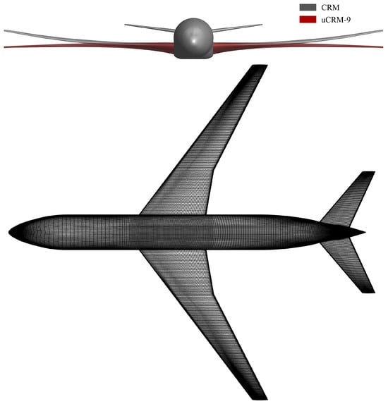
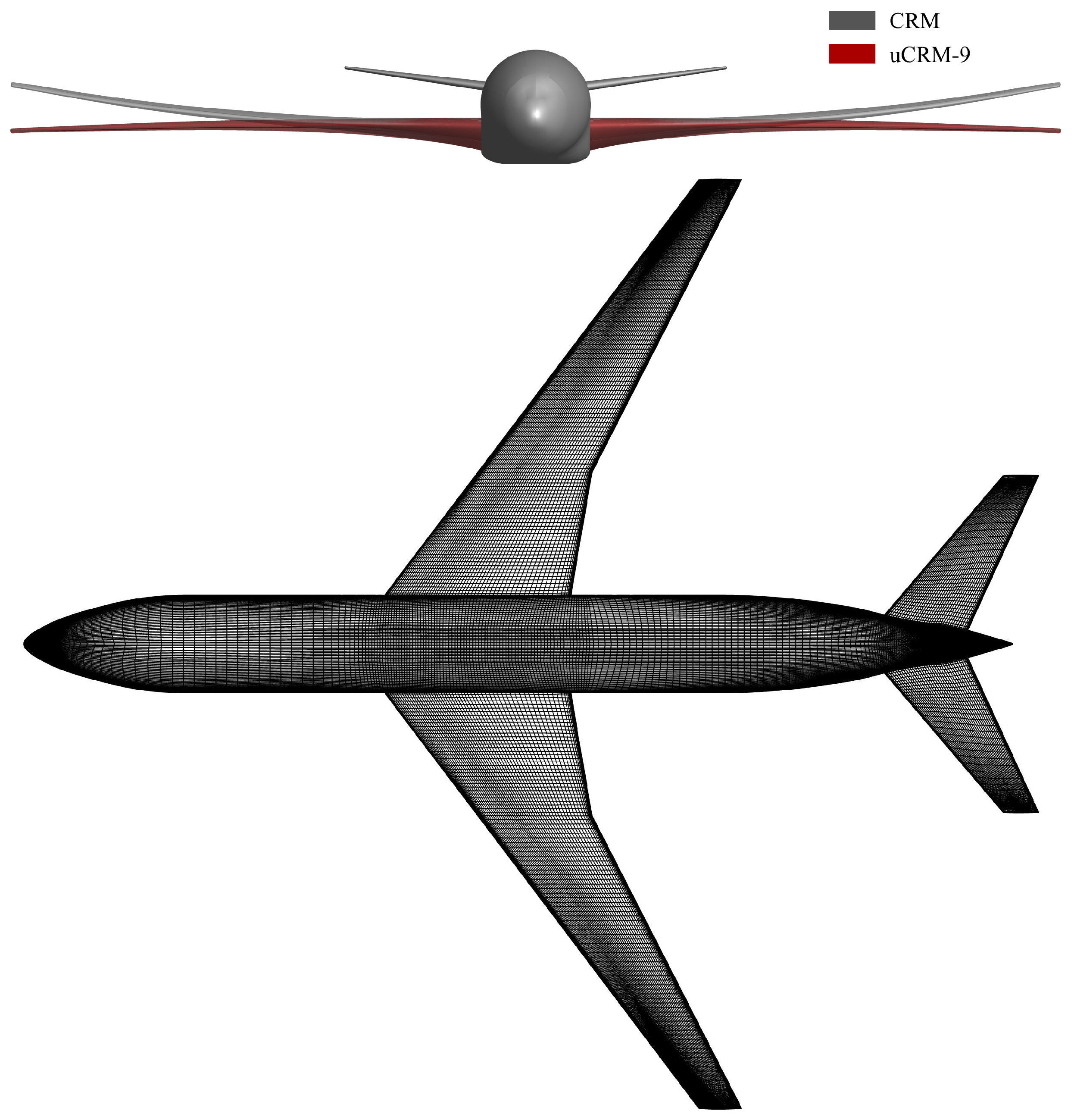
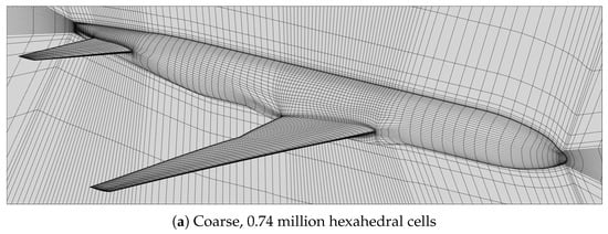
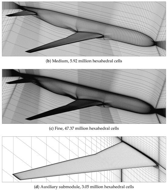
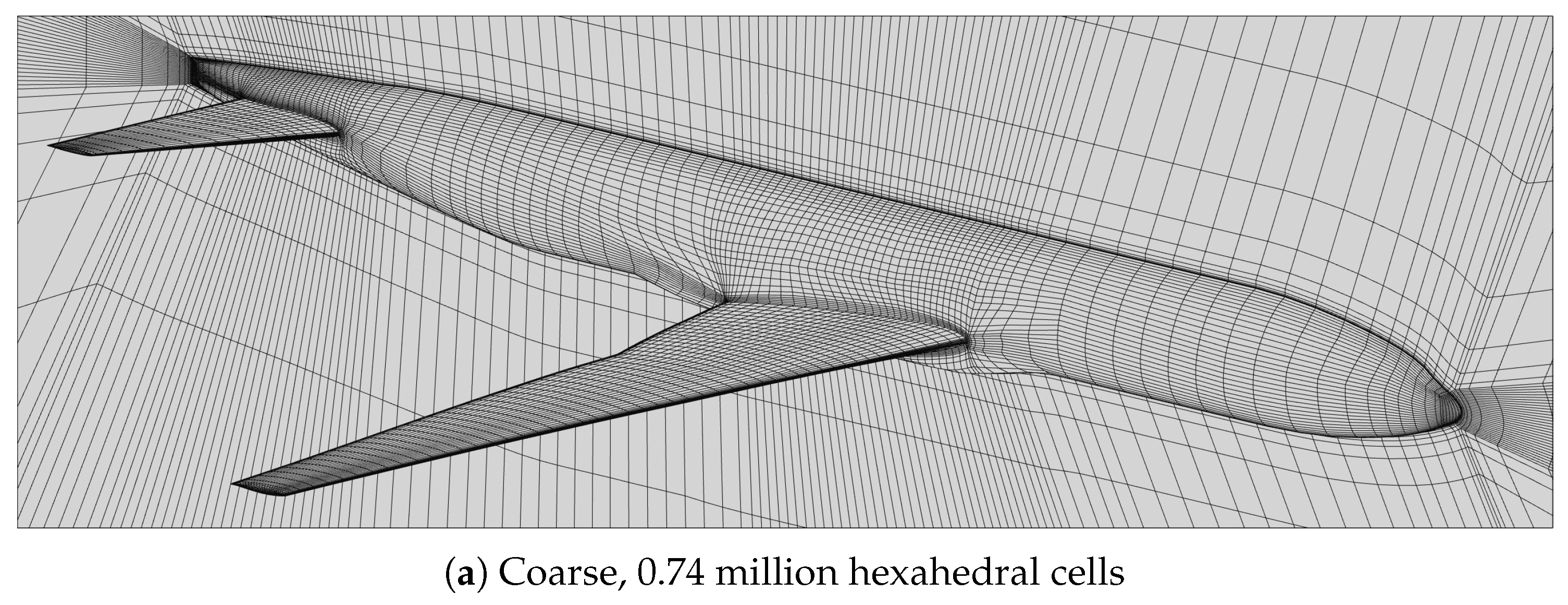
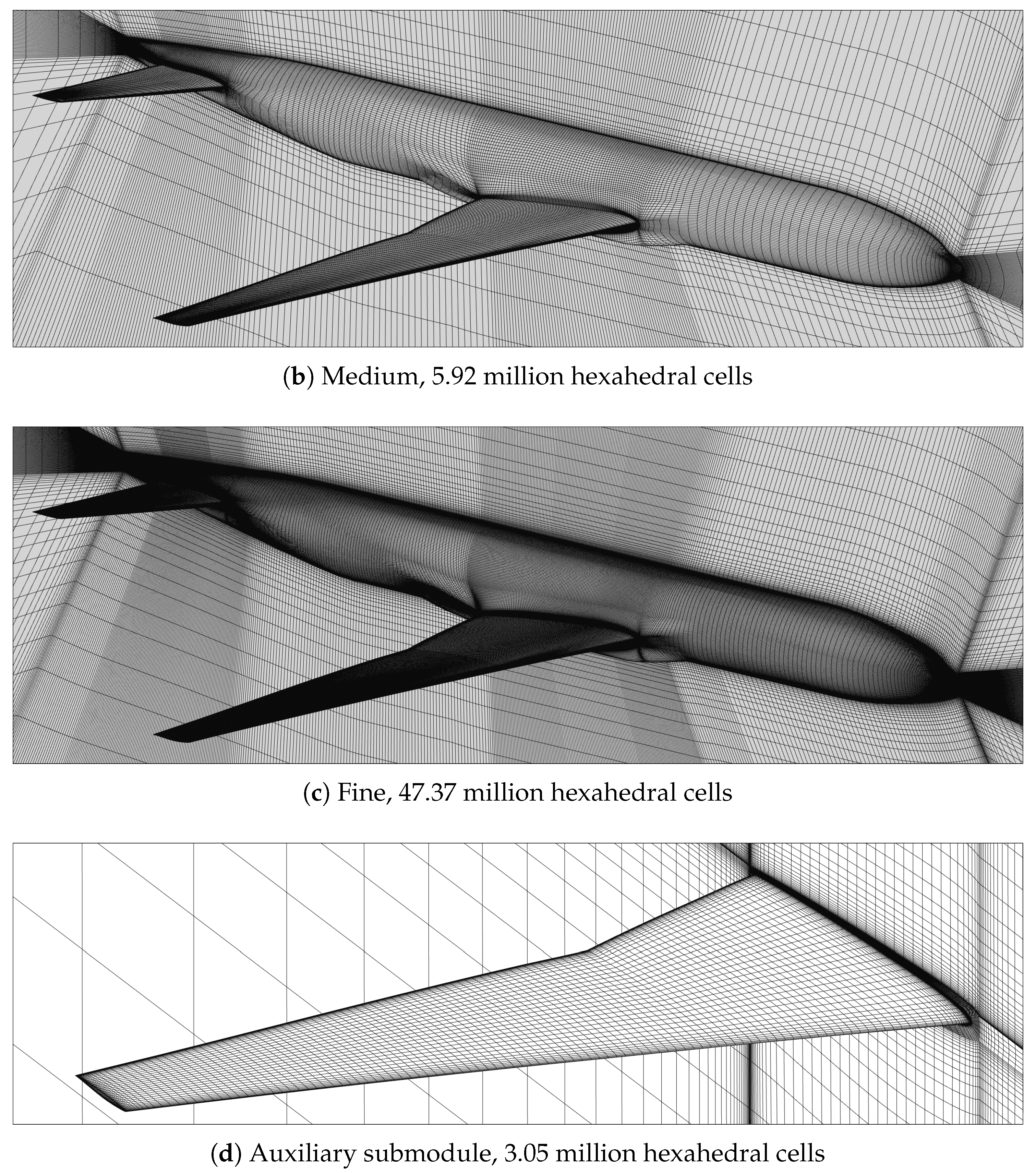
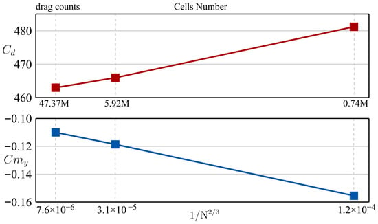
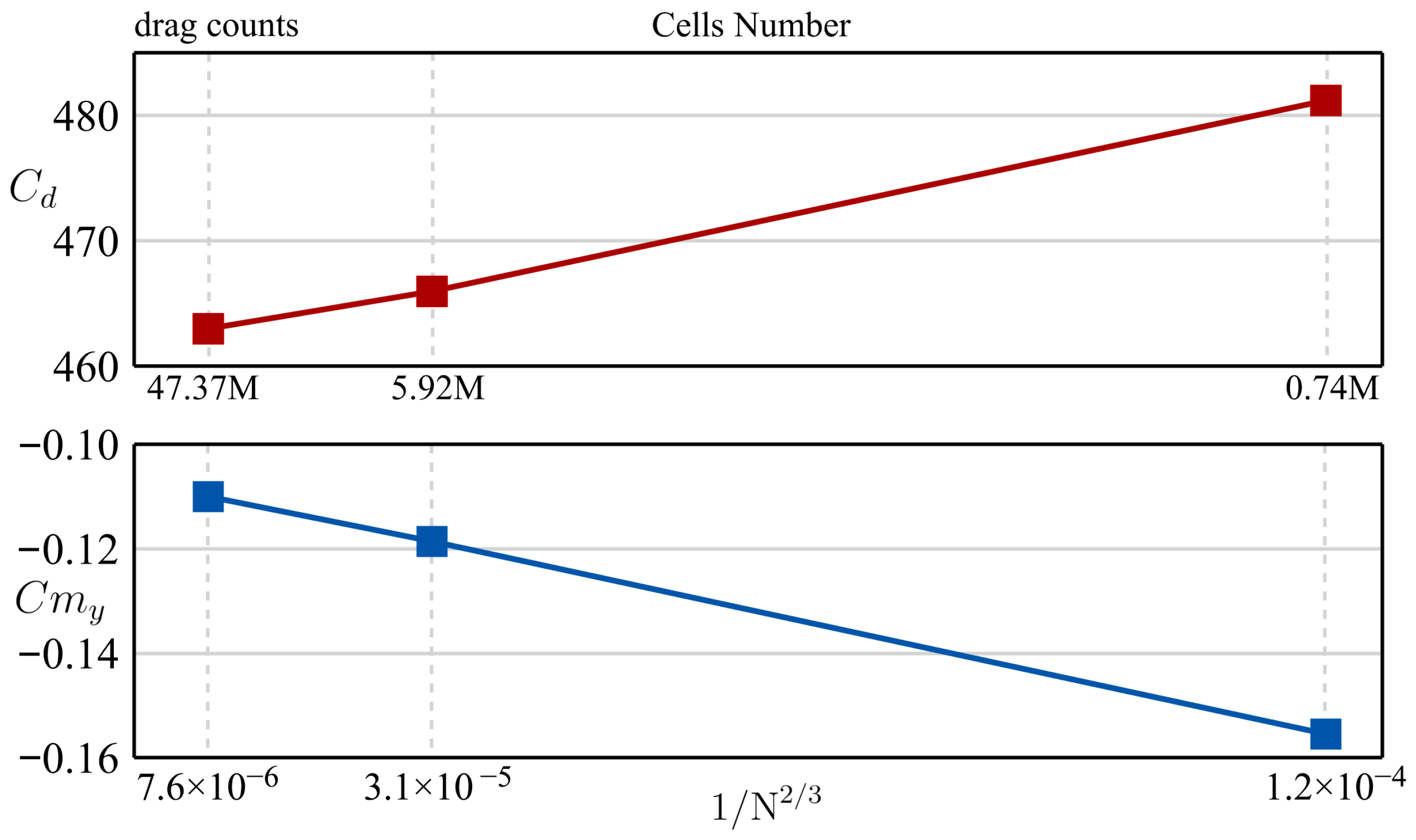
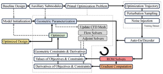
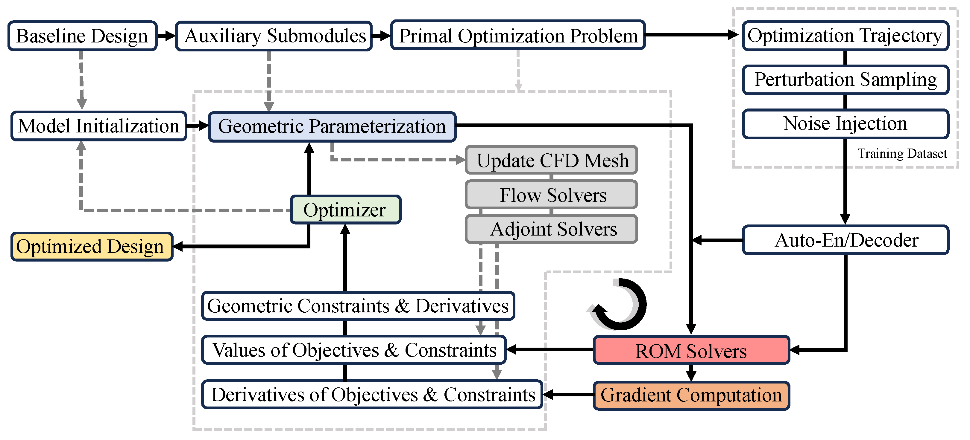
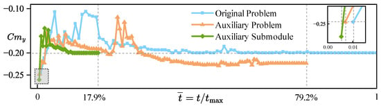
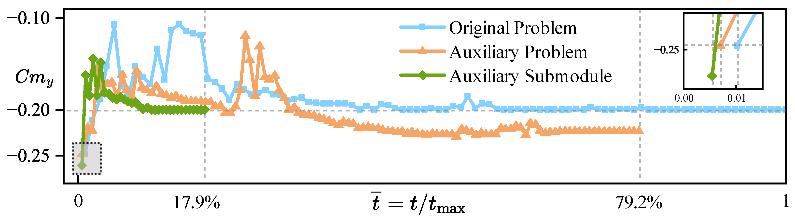
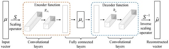
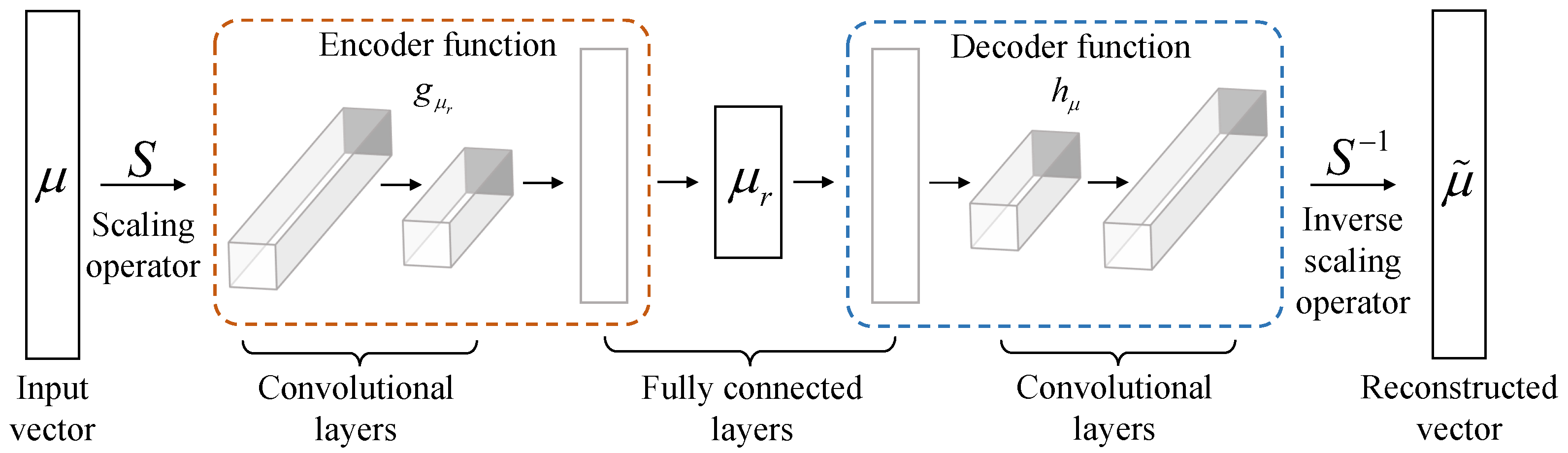
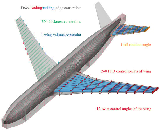
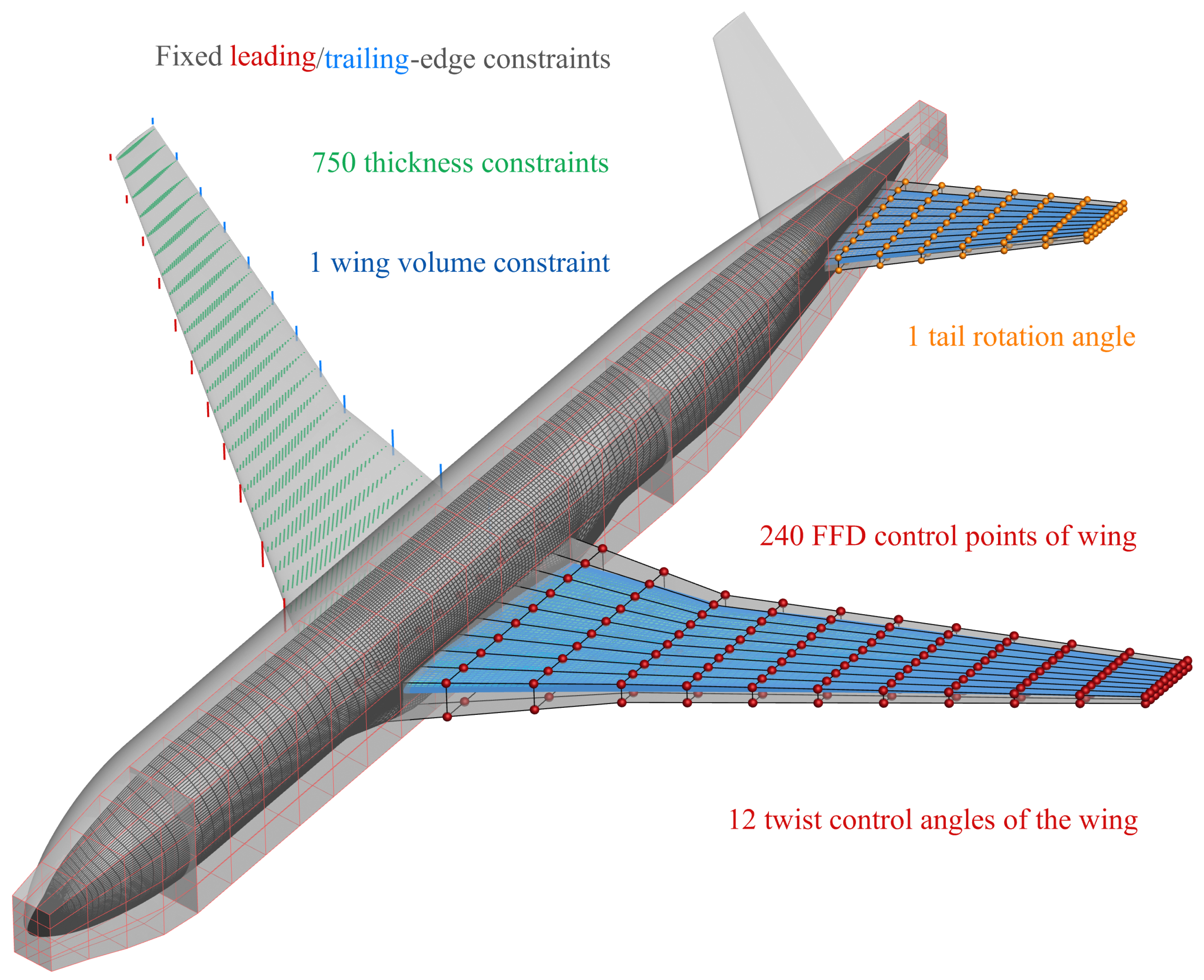
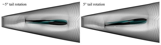
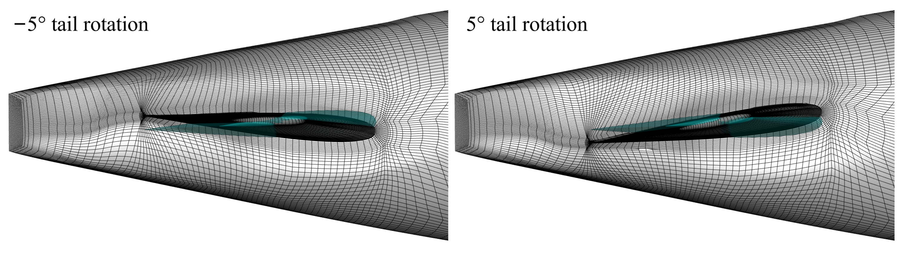
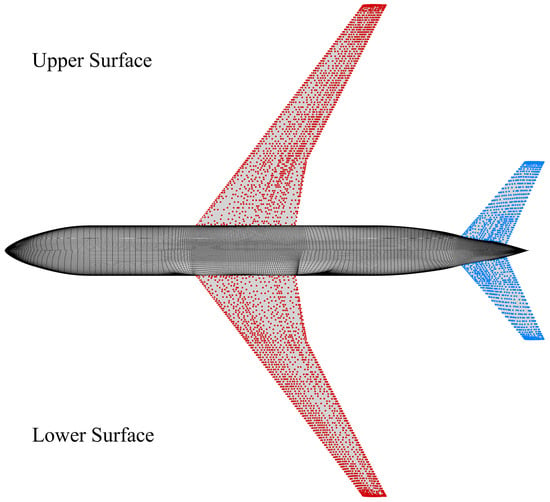
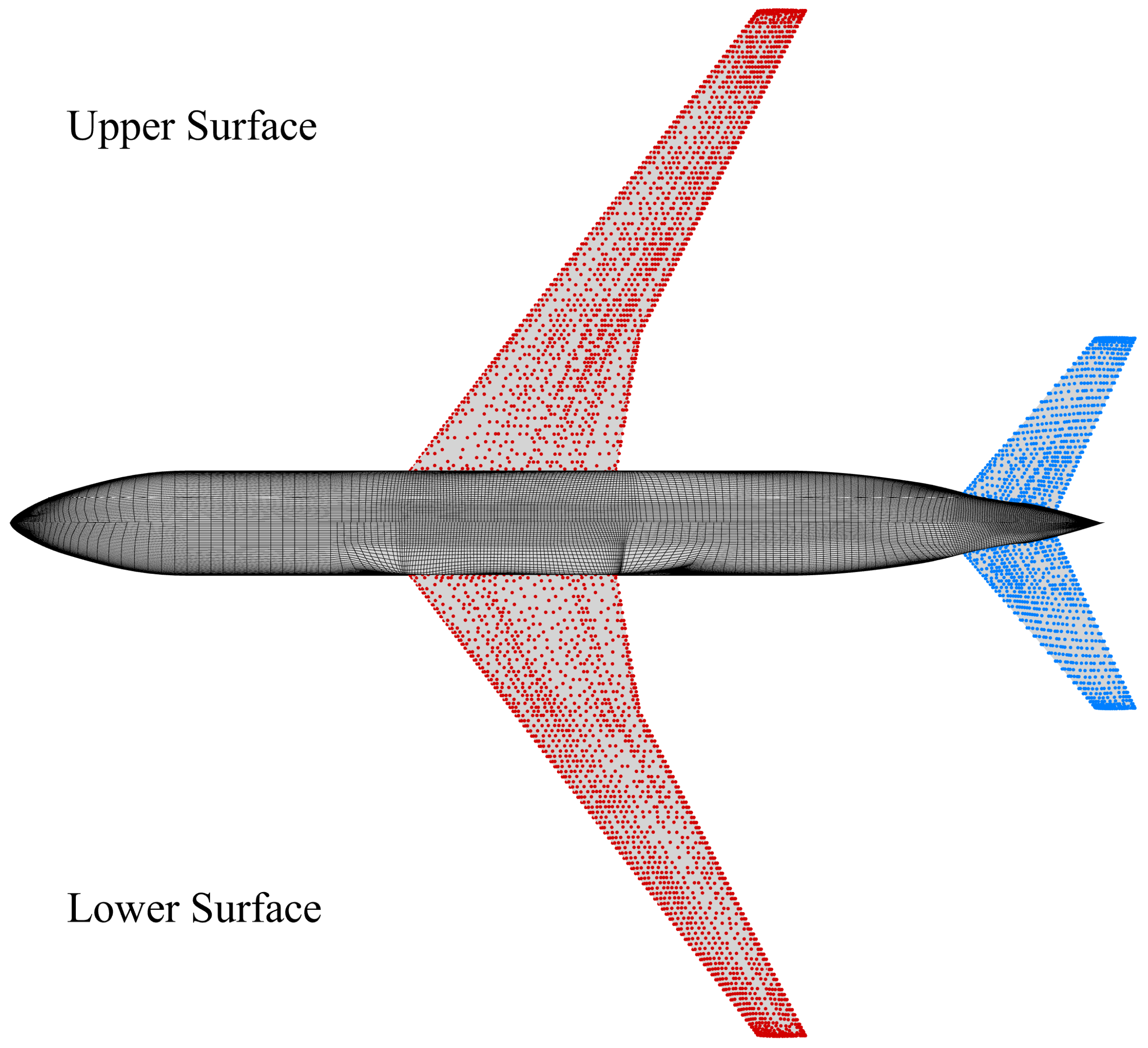
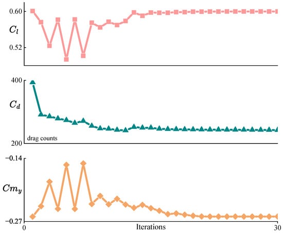
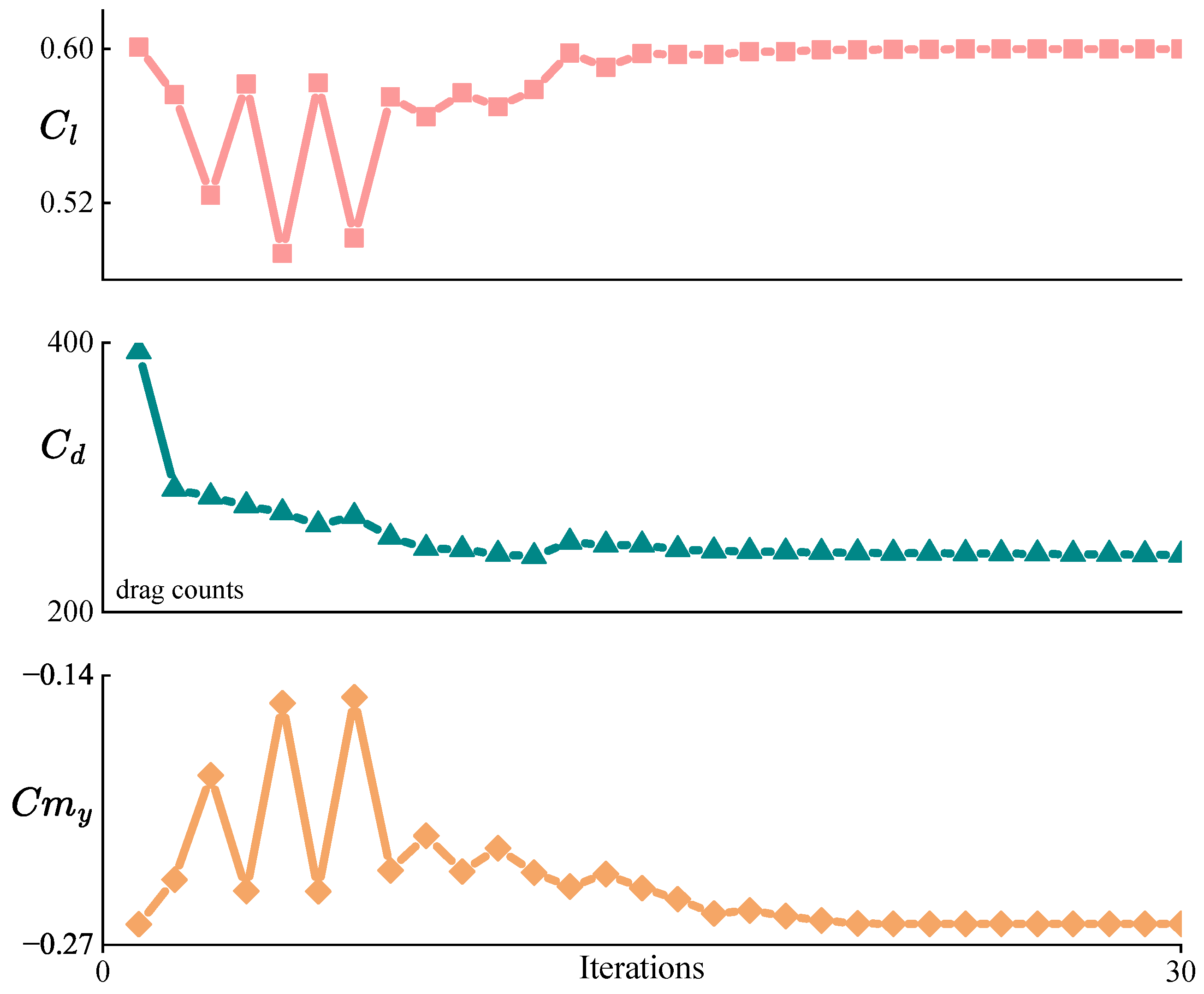
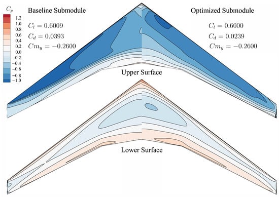
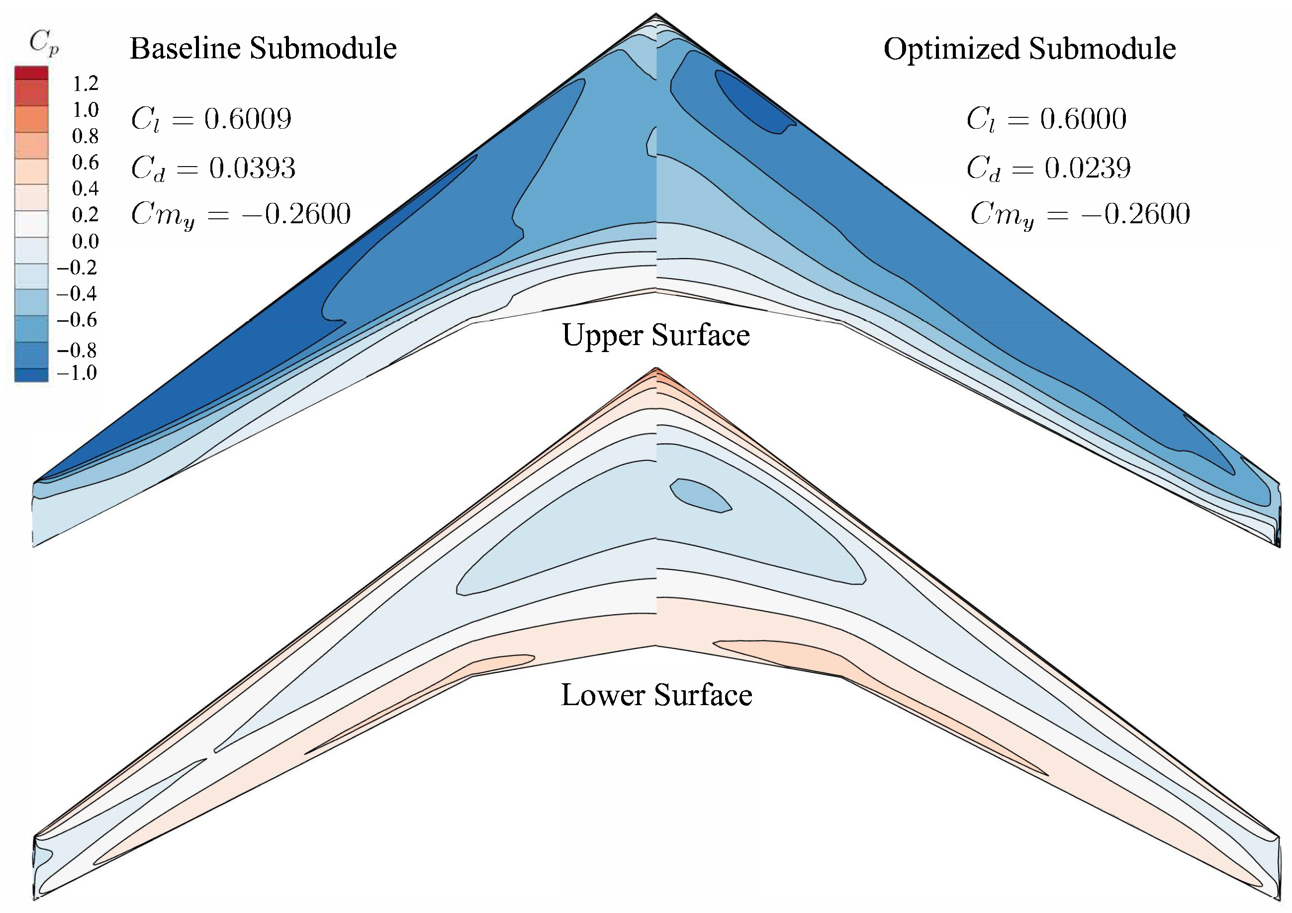
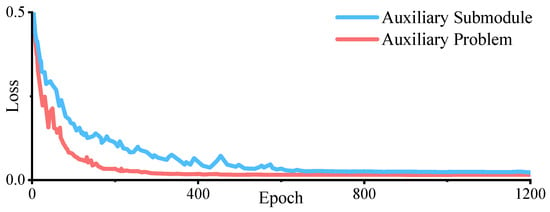
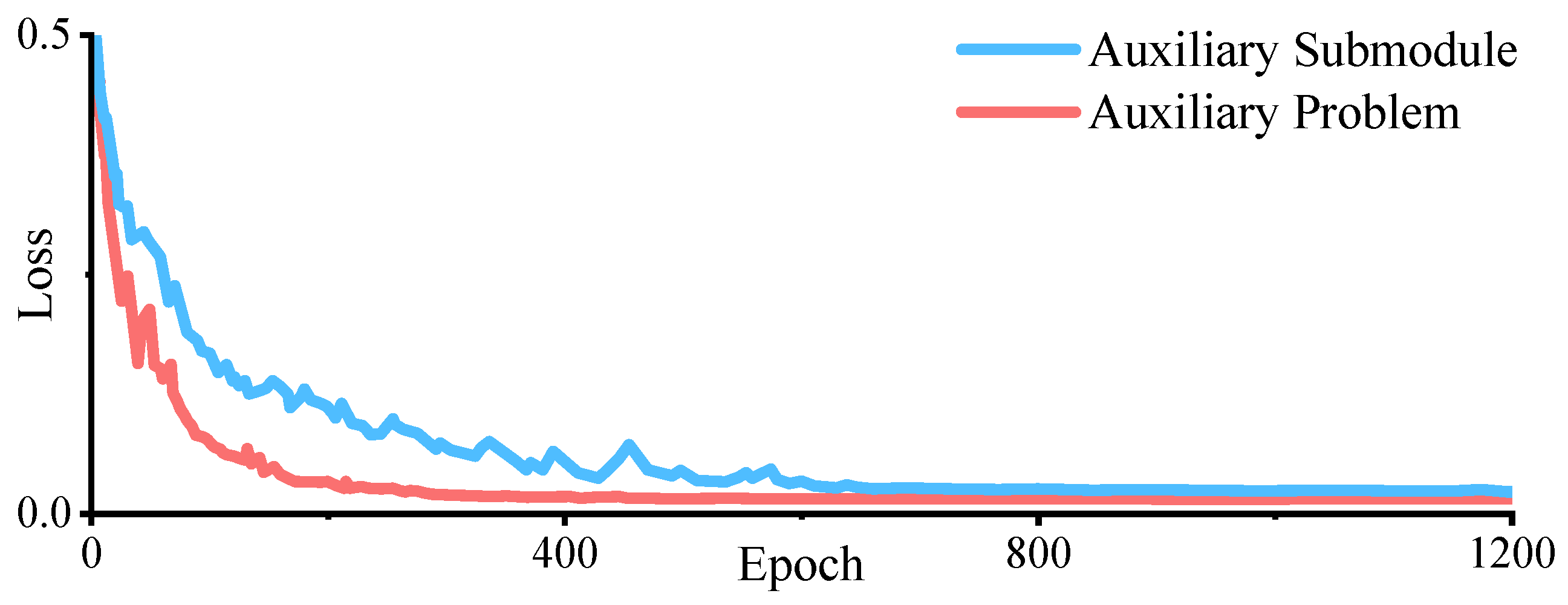
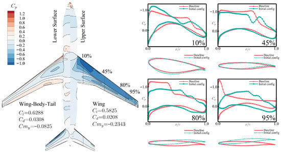
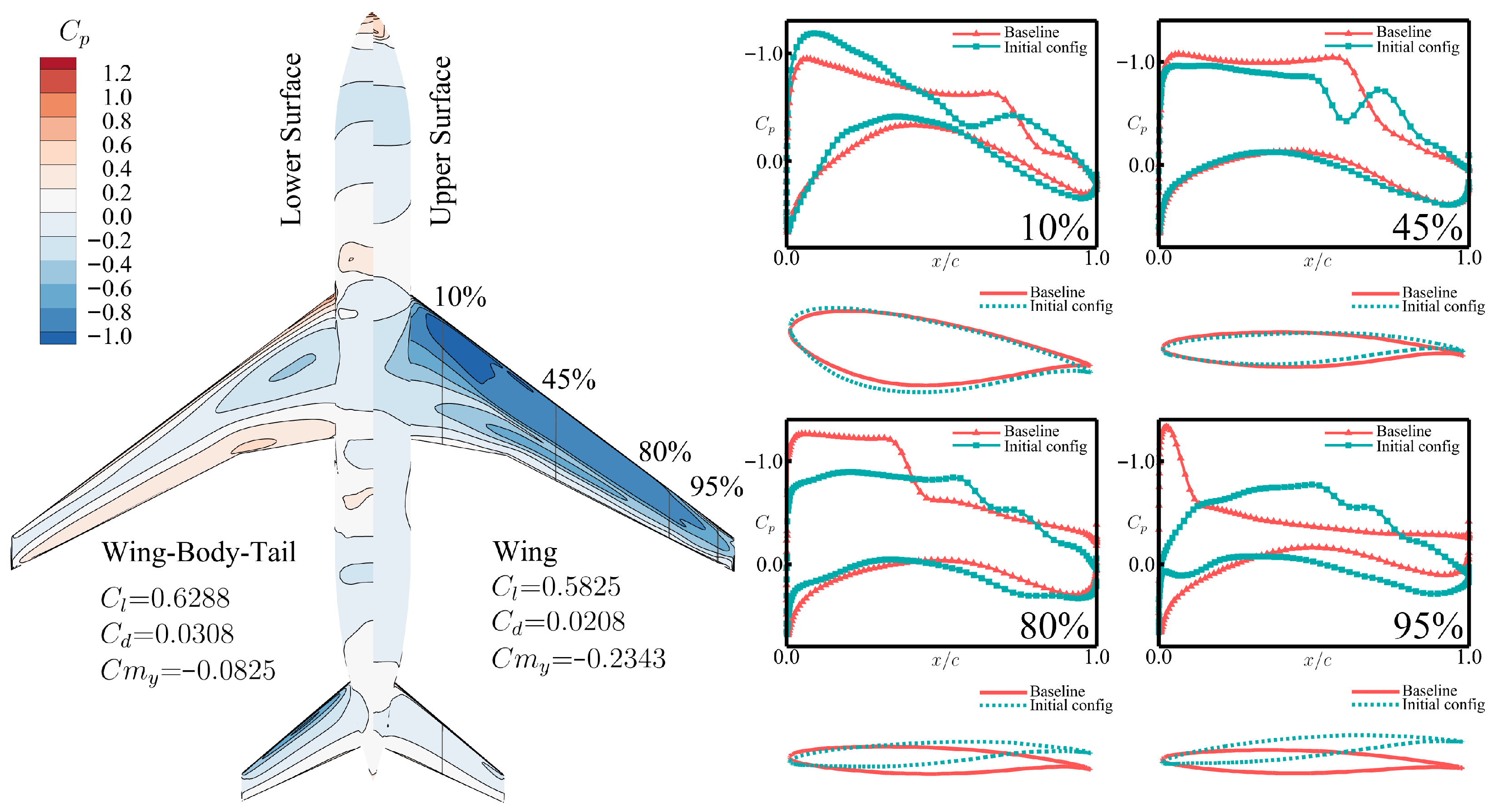
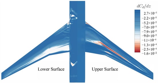
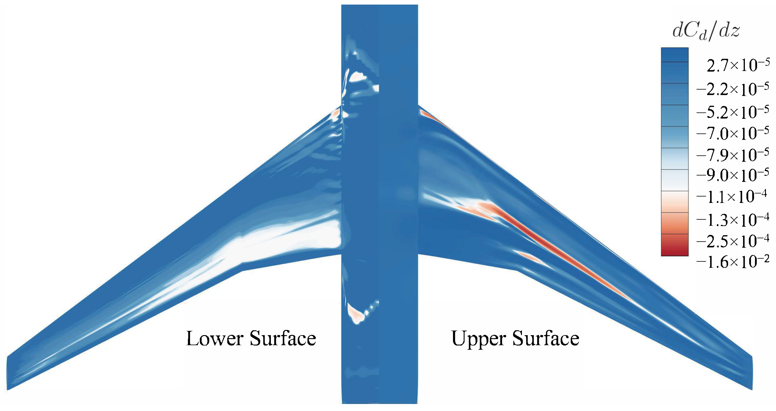
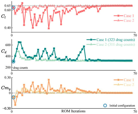
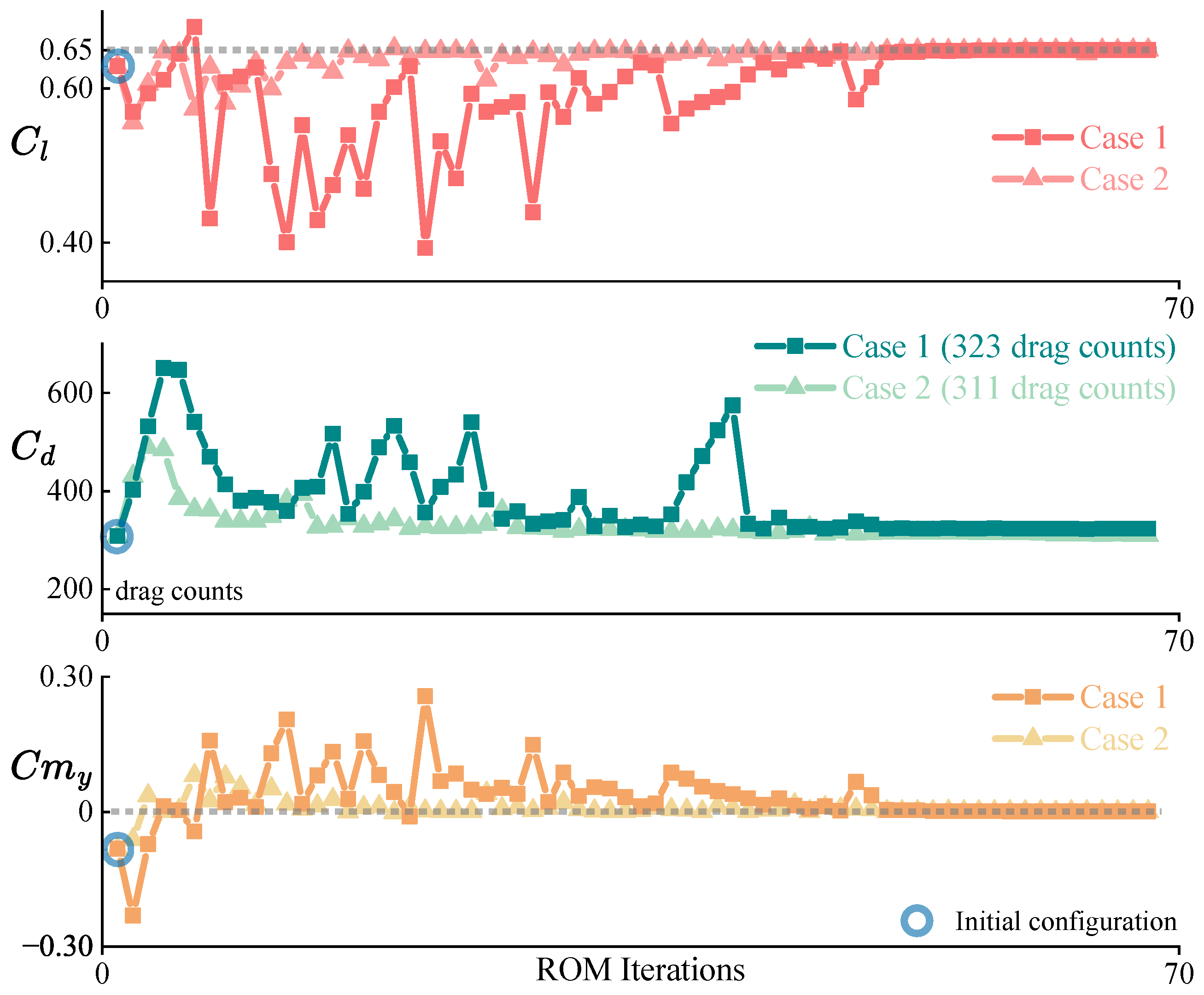
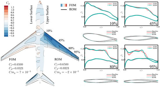
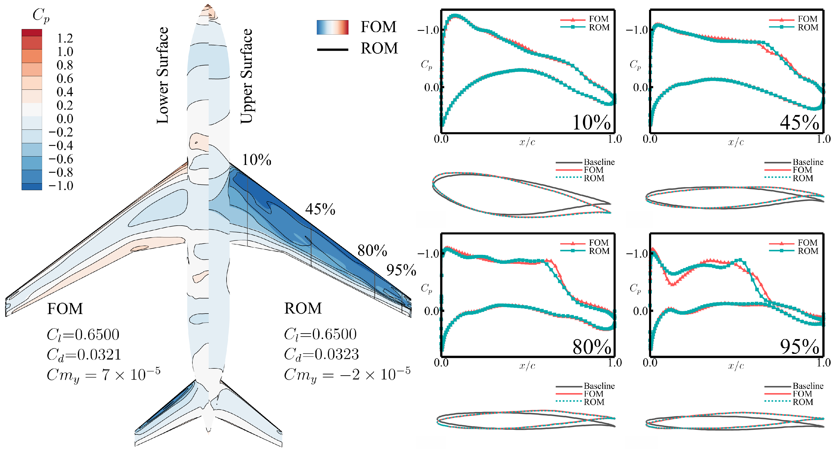
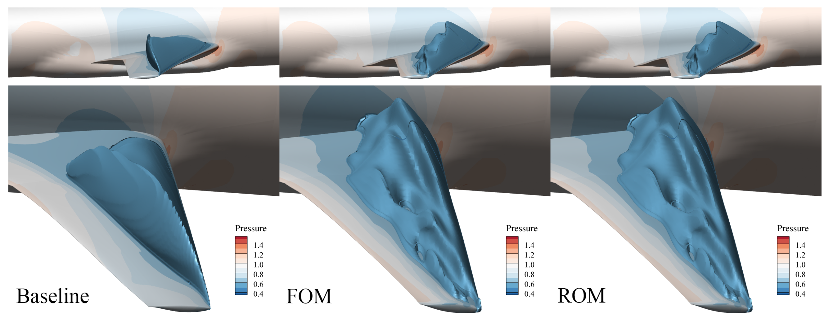
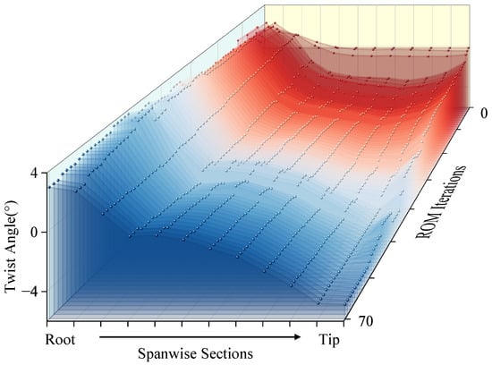
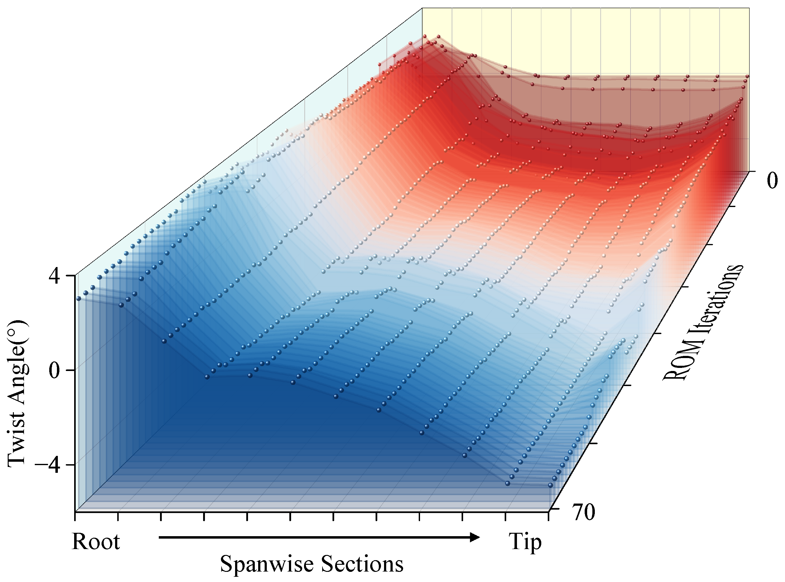
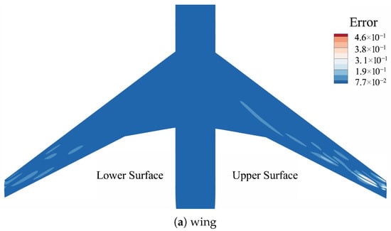
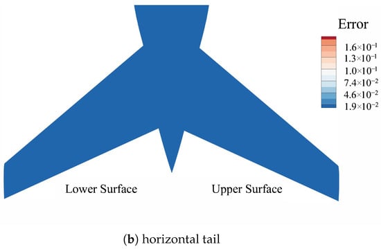
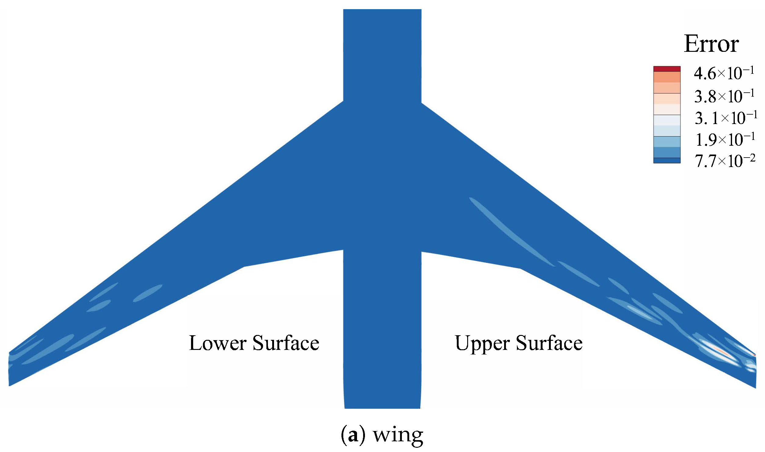
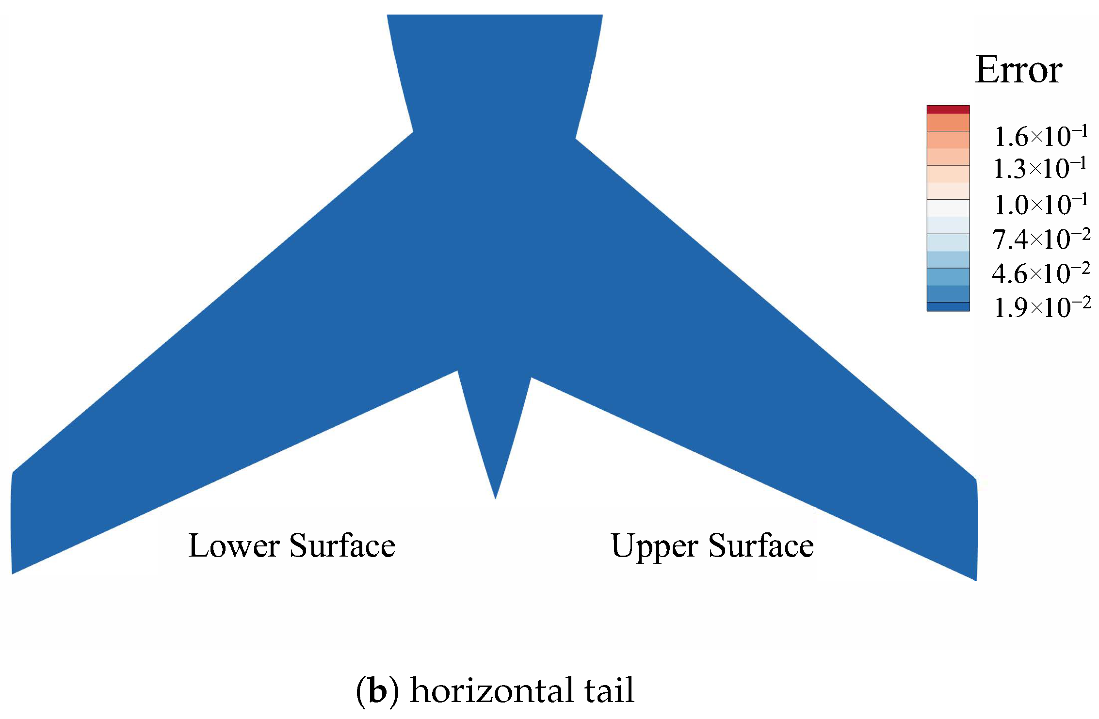
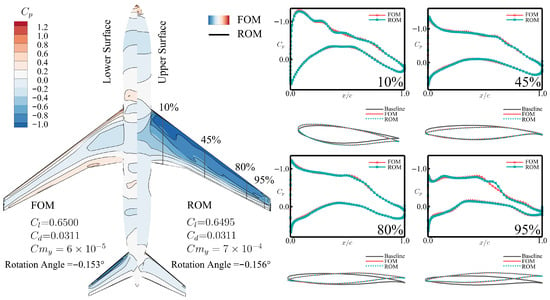
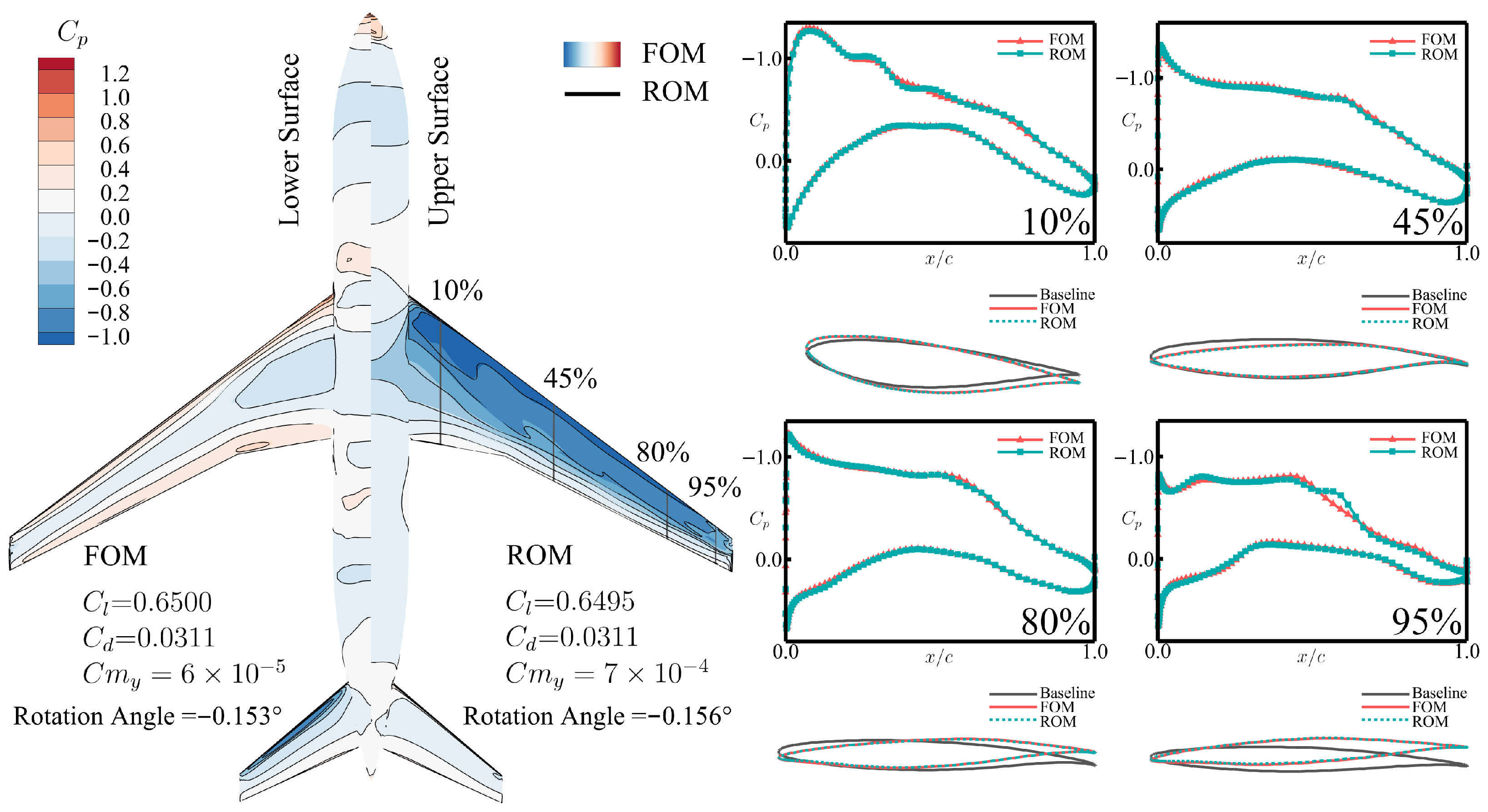
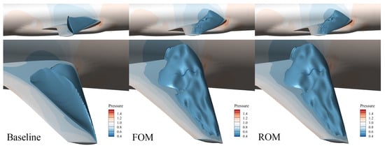
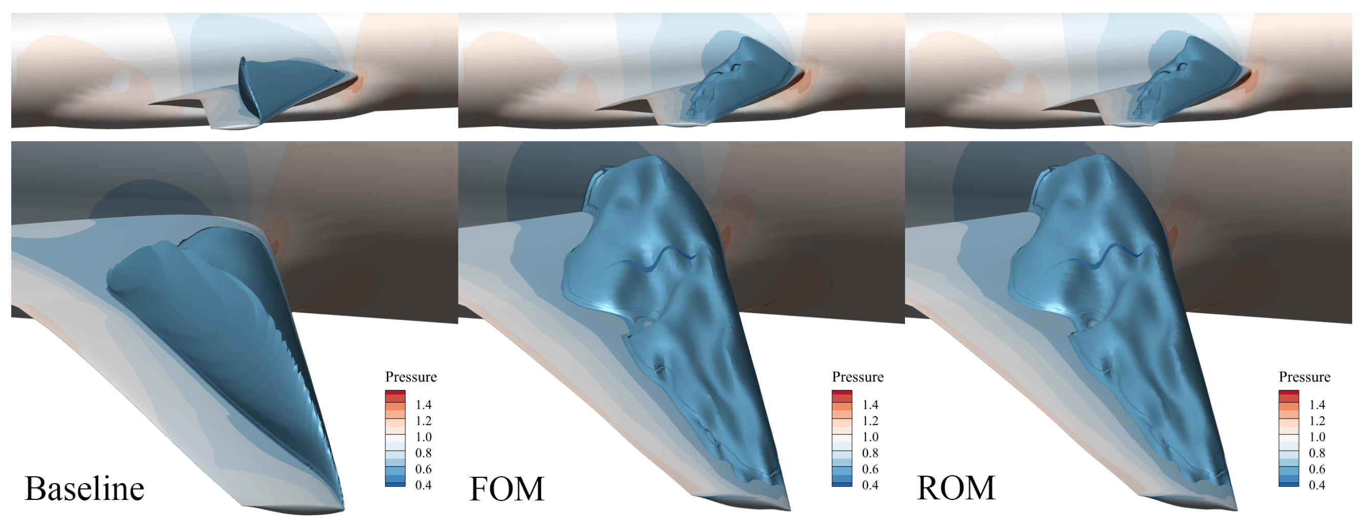
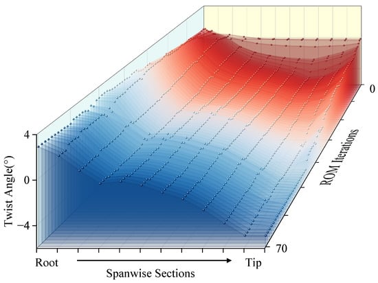
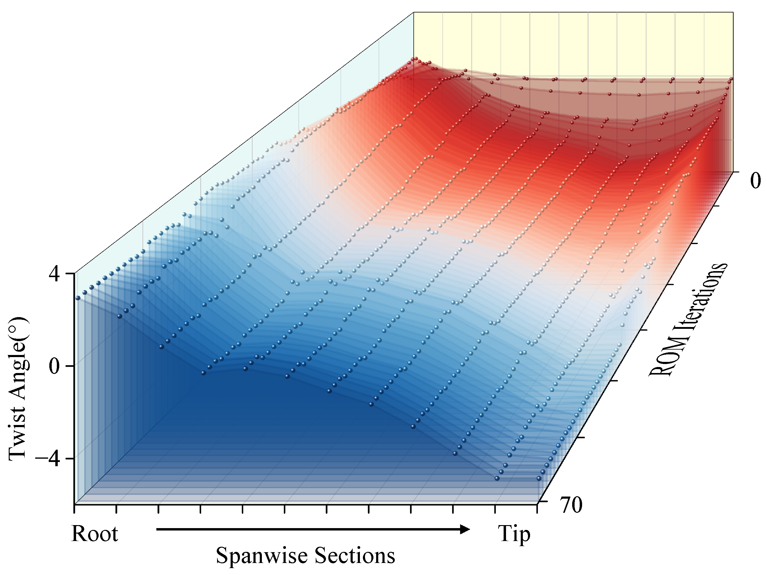
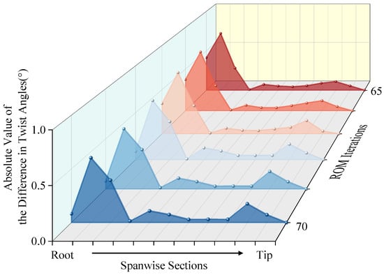
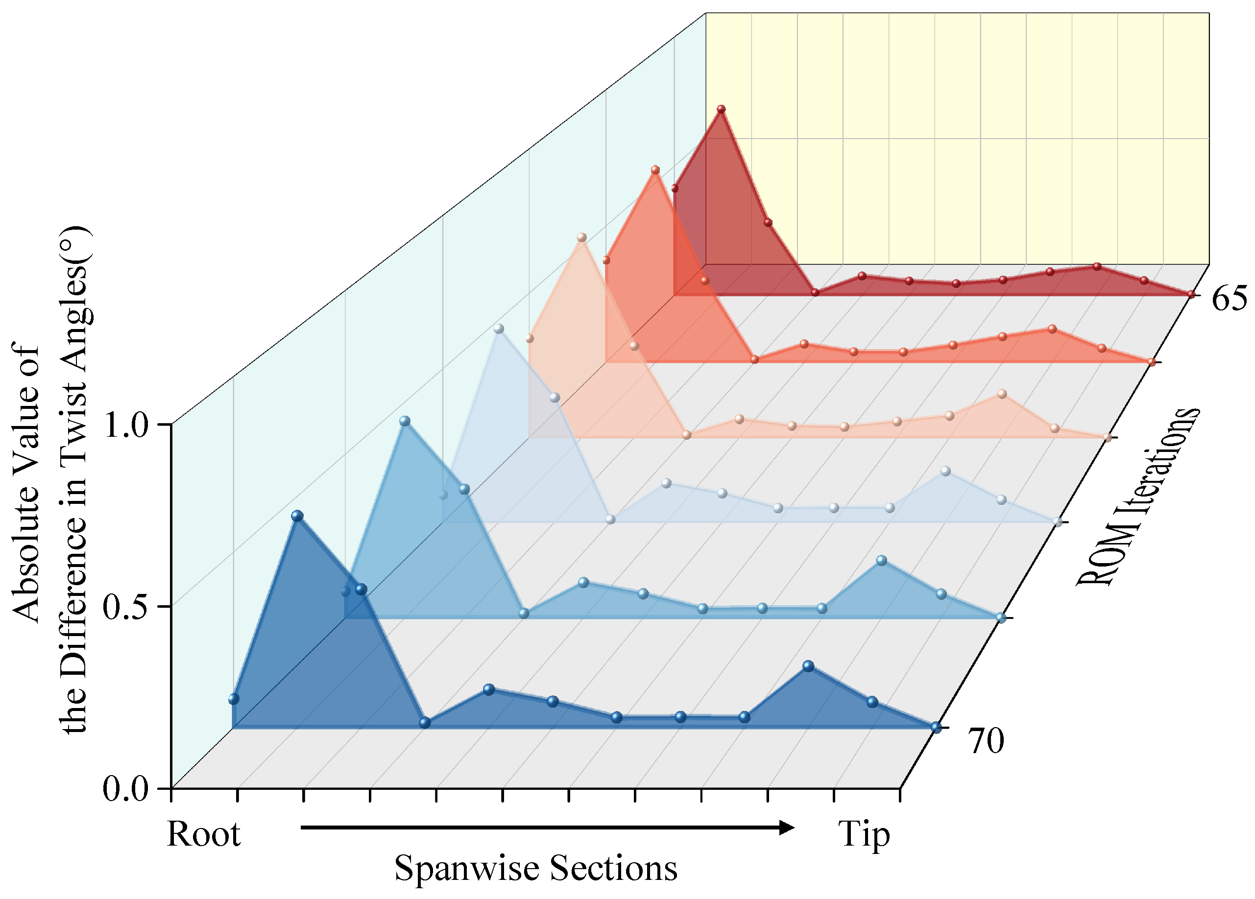
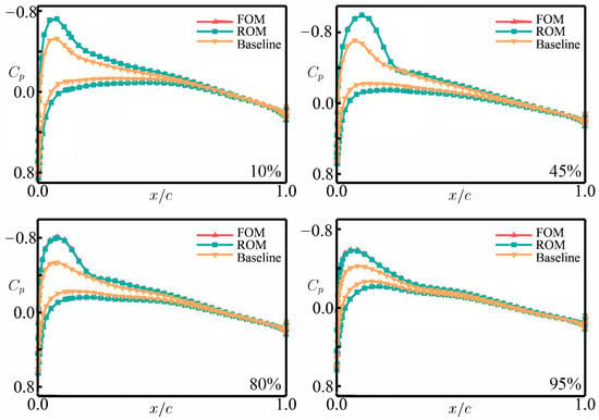
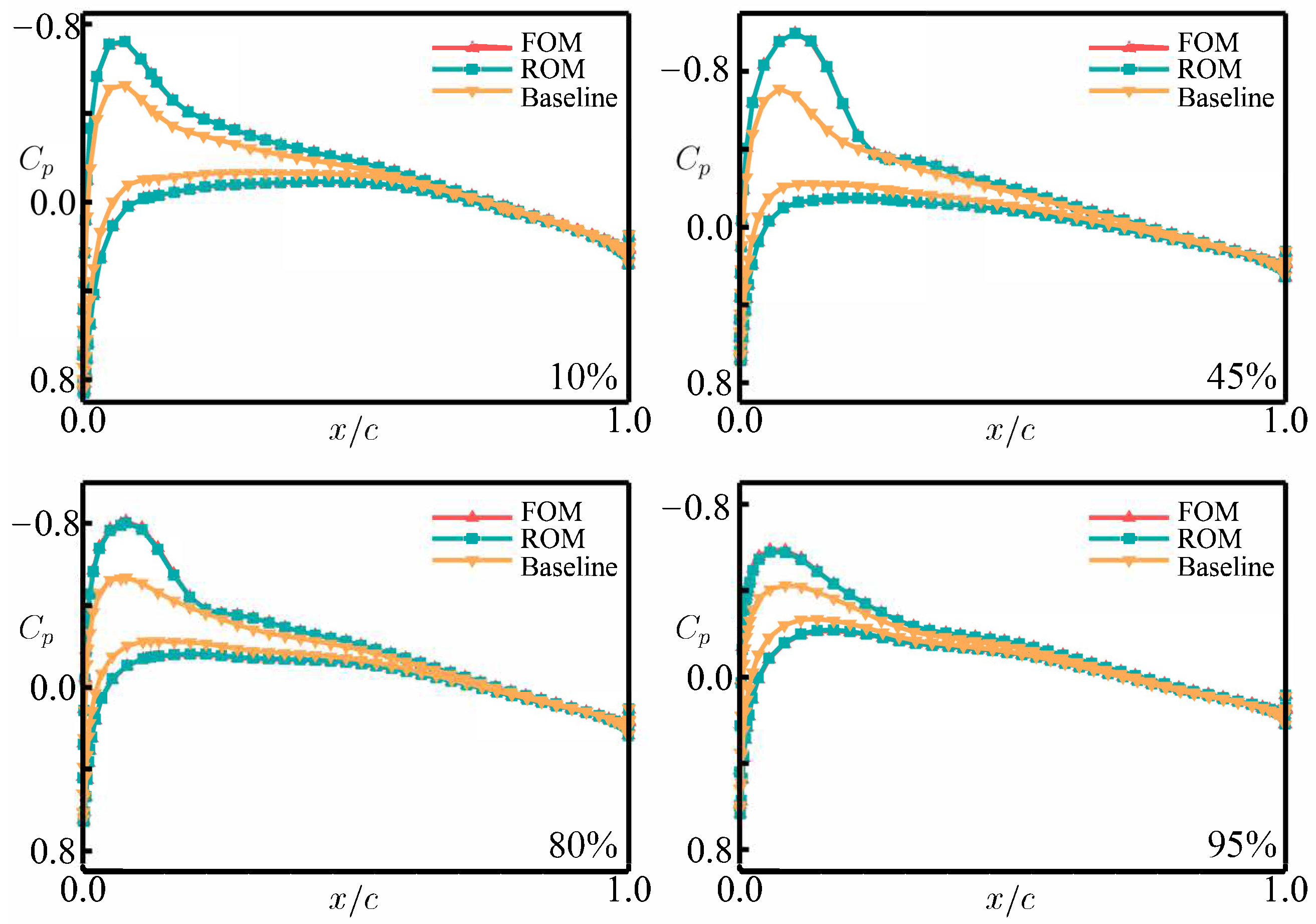
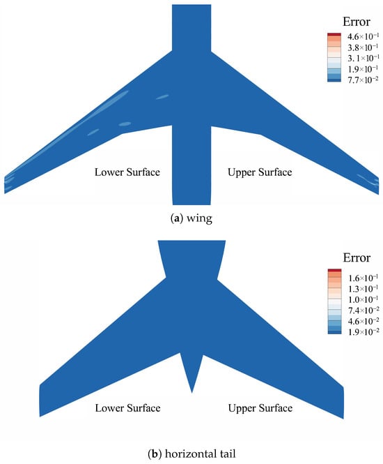
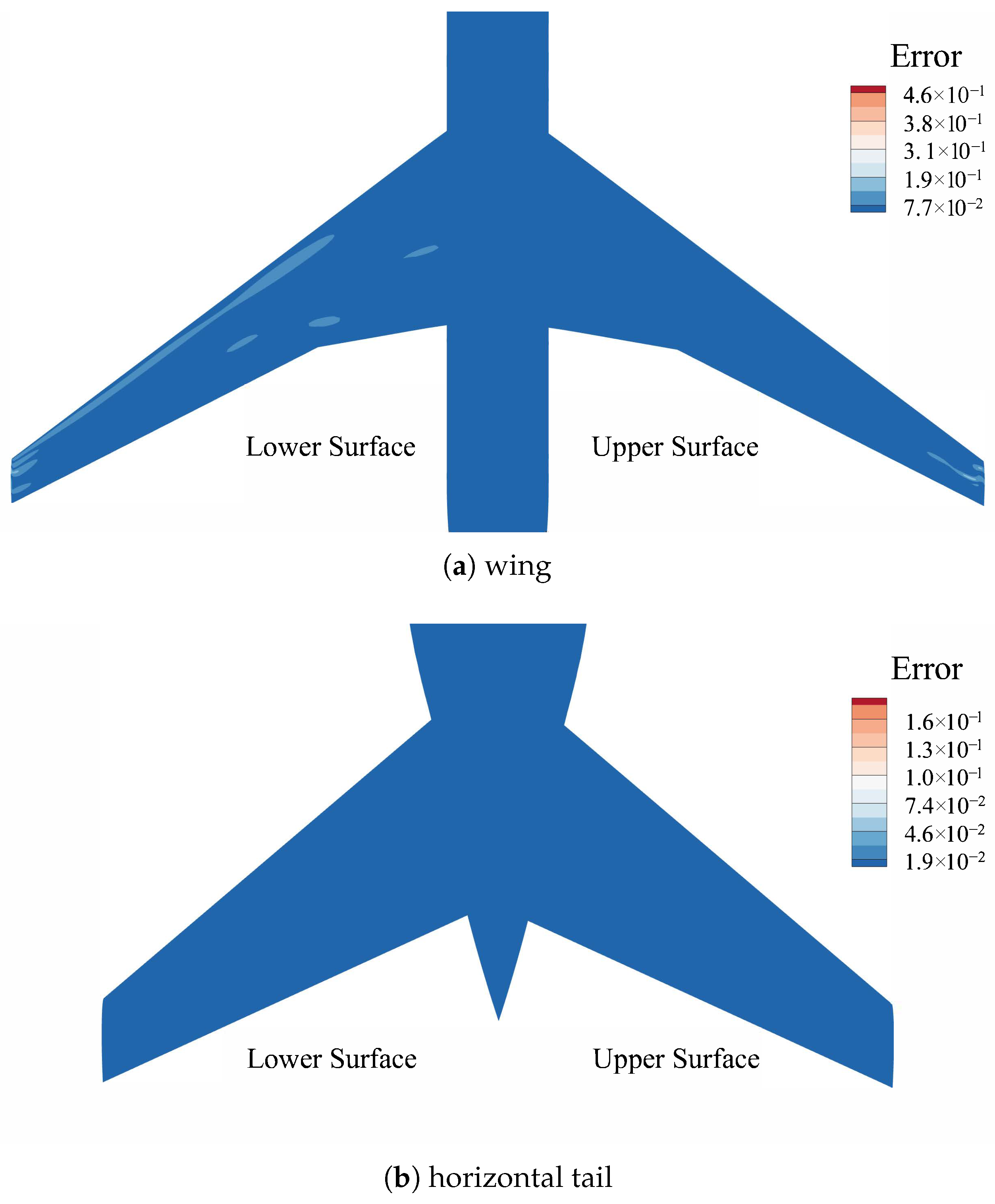
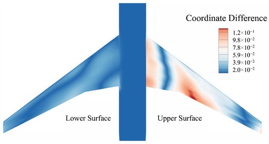
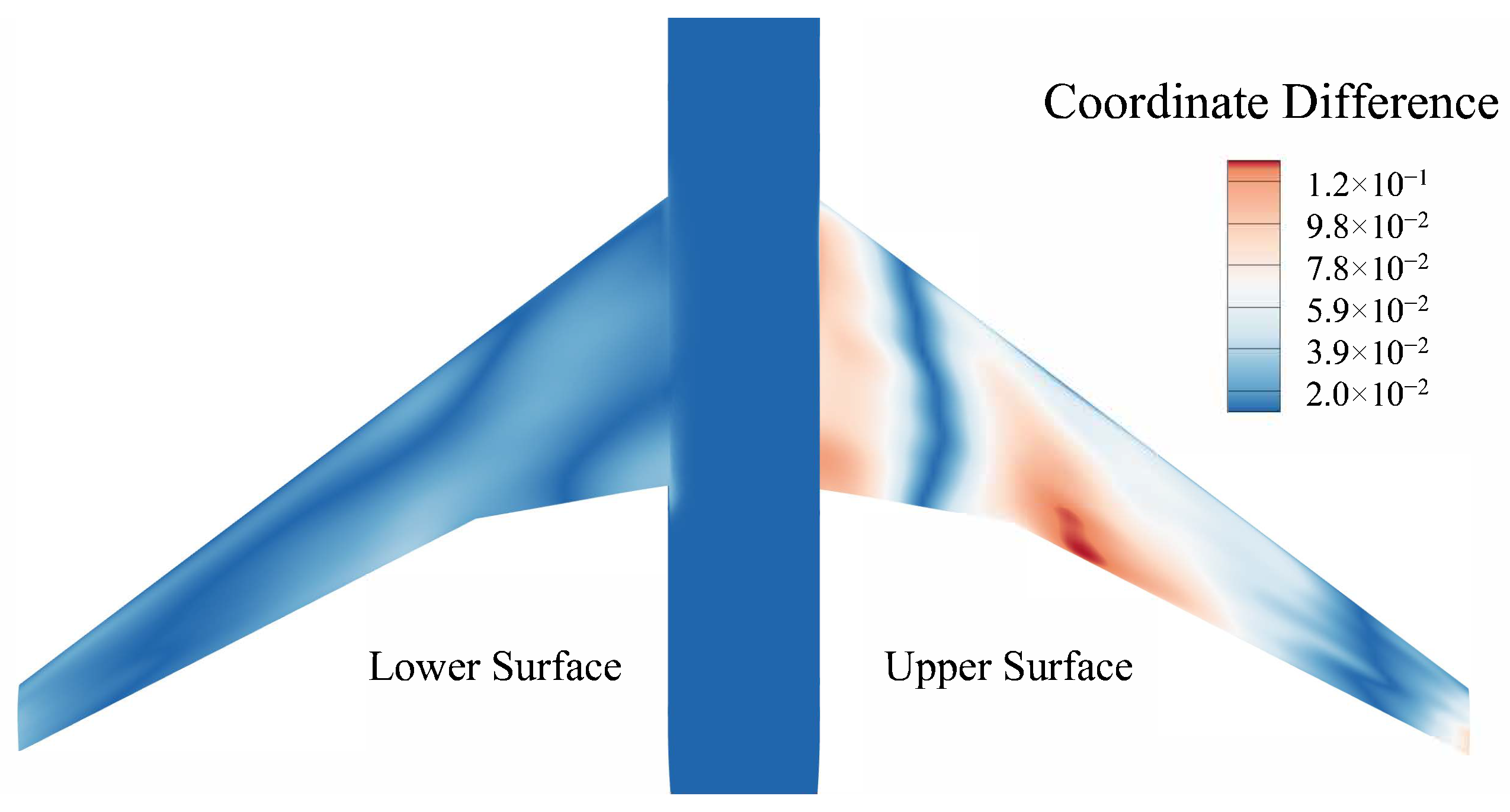
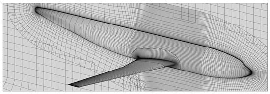
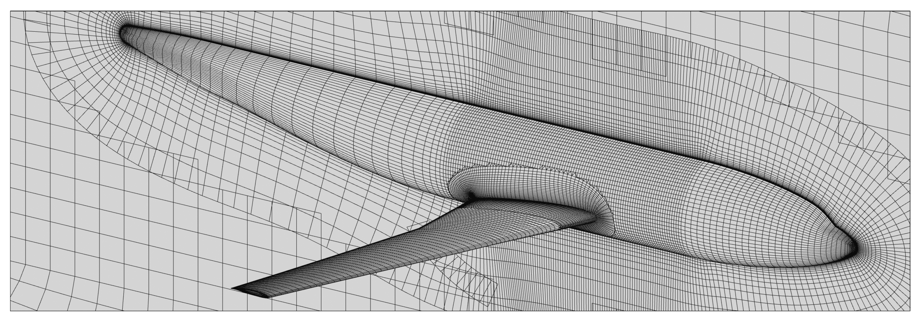
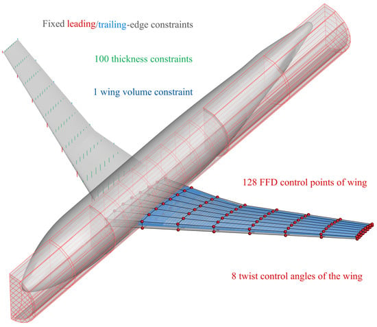
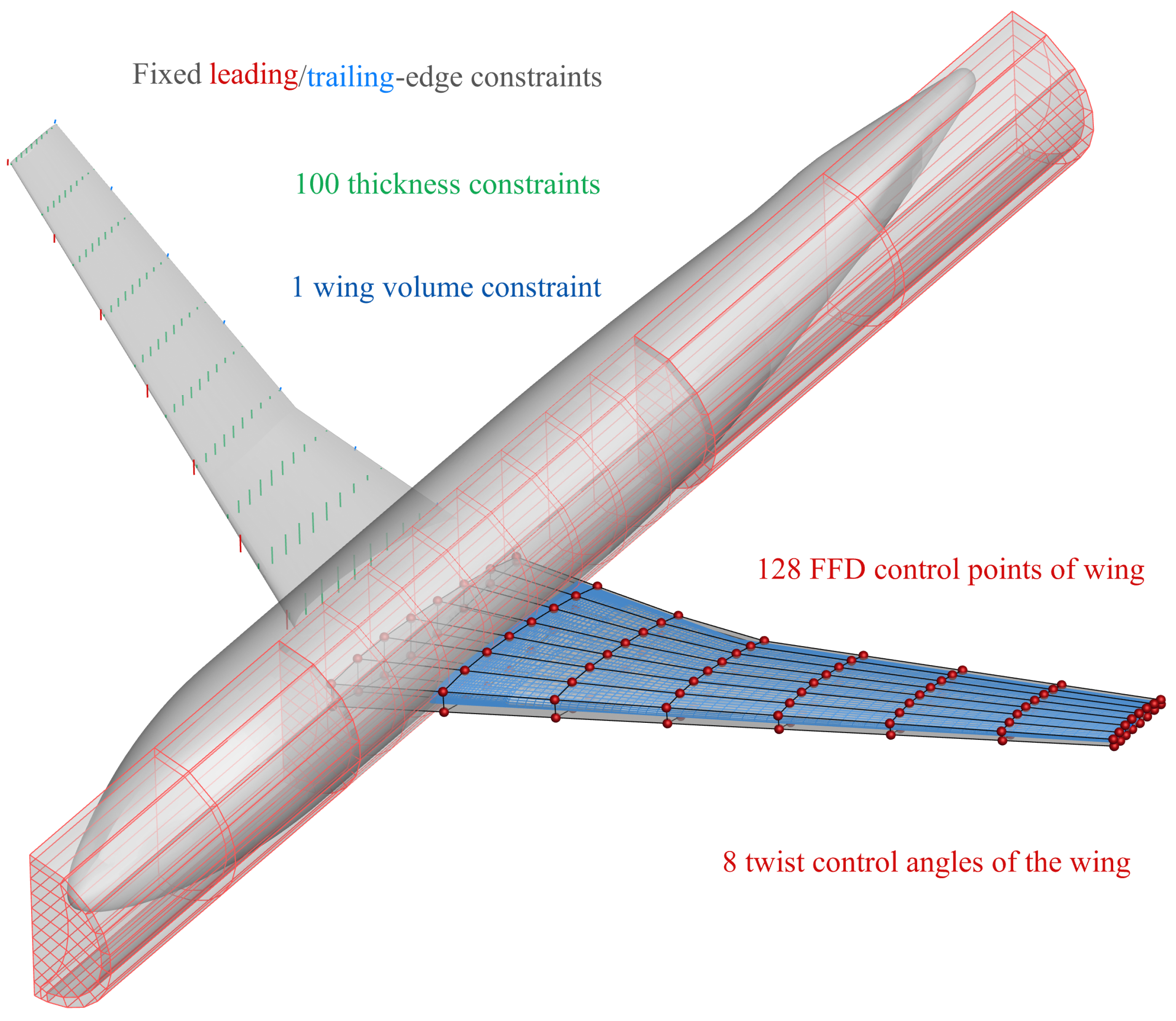
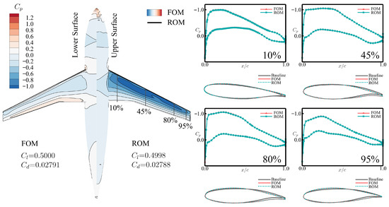
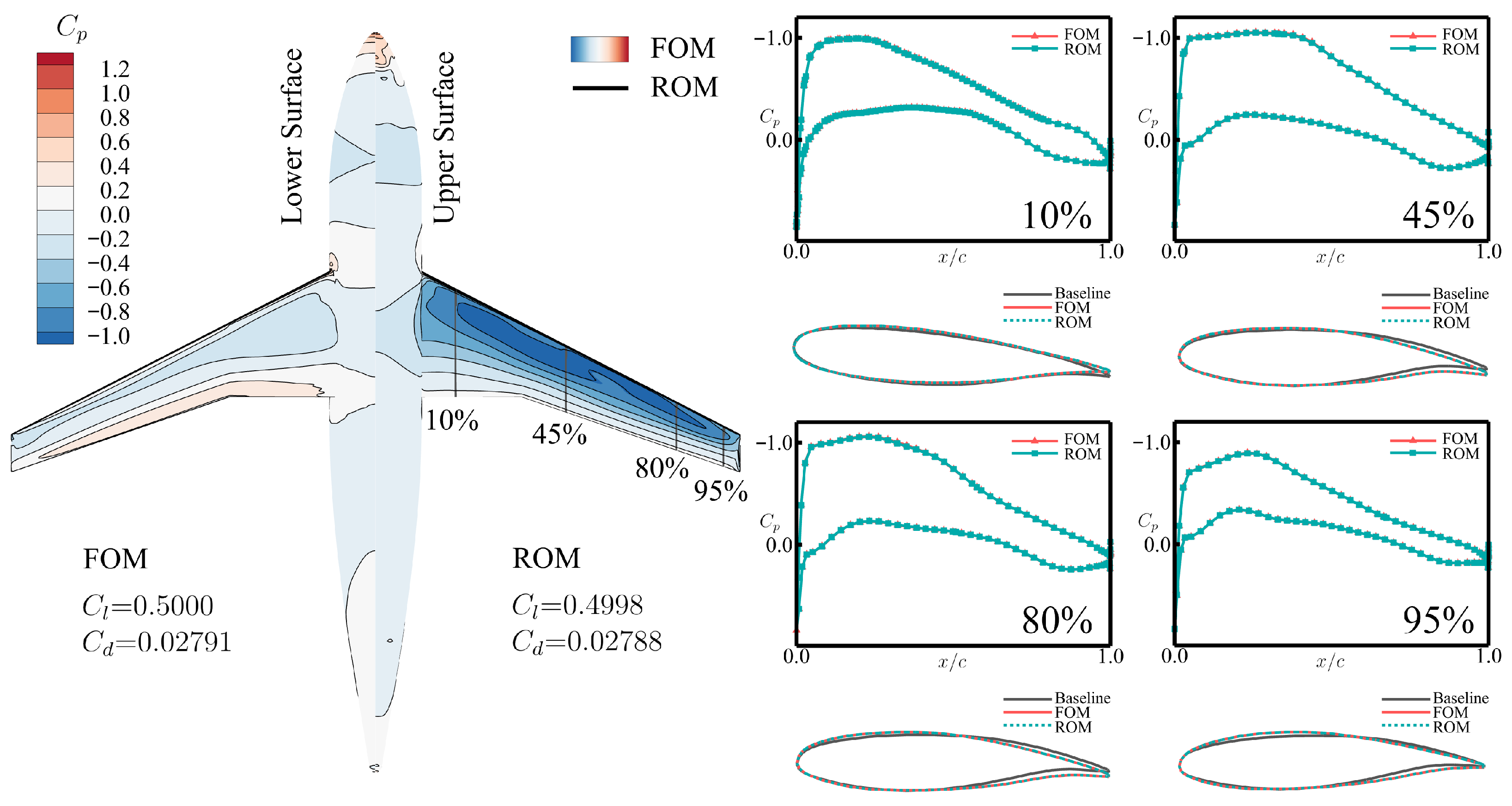

Disclaimer/Publisher’s Note: The statements, opinions and data contained in all publications are solely those of the individual author(s) and contributor(s) and not of MDPI and/or the editor(s). MDPI and/or the editor(s) disclaim responsibility for any injury to people or property resulting from any ideas, methods, instructions or products referred to in the content. |
© 2026 by the authors. Licensee MDPI, Basel, Switzerland. This article is an open access article distributed under the terms and conditions of the Creative Commons Attribution (CC BY) license.