


Abstract
Liquid hydrogen (LH2) as an energy source is viewed as a potential path to achieve carbon neutral commercial aviation, albeit accompanied by a plethora of structural, thermal and safety challenges that still need to be resolved. With respect to a LH2 tank’s structural integration aspect, static, damage tolerance and impact/crashworthiness responses need to be investigated. Ιn the present work, an efficient structural integration concept of LH2 tanks into a Regional Commercial Aircraft fuselage is proposed, analyzed and preliminary designed, as part of the Clean Aviation project HERFUSE. The main purpose of the work is the feasibility assessment of introducing adhesively bonded solutions in the connection of LH2 tanks to the aircraft fuselage. The initial design of the potential mounting system configuration was investigated via a finite element parametric simulation model that was developed for this purpose and used to analyze different variations in the proposed concept, under certification relevant load cases. Different variations in the mounting system were assessed, considering their effect on the stress concentrations developed in the fuselage and the tank structure, as well as induced deformations and potential joints debonding. The results indicated that the utilization of adhesive bonding elements in the design of an LH2 tank integration system is conceptually efficient, although the specific configuration-related shortcomings that were identified need to be tackled. As far as the preliminary design study results are concerned, the minimum required number of joining elements were identified and an initial mass prediction of the mounting system was performed to be used as initial value in the entire hybrid–electric novel aircraft design loop. Future studies on the detailed design and sizing of the mounting system, as well as to incorporate dynamic crash analyses and implementation of energy absorbing elements are needed.
1. Introduction
The aviation sector currently accounts for approximately 2.5% of global CO2 emissions. Following the COVID-19 pandemic, the industry has rebounded, and global air travel demand is projected to double by 2050. Even by assuming that the current pace of technological advancements will keep on, the net-zero carbon emissions goal of aviation by 2050 is not achievable without a disruptive technological breakthrough. This means that meeting the set ambitious climate targets requires radical aircraft redesigns that revisit fundamental design assumptions which have remained largely unchanged for decades such as electric and hydrogen propulsion. The adoption of liquid hydrogen (LH2) as an aviation fuel introduces substantial challenges related to storage, integration, safety, and certification. In contrast to conventional kerosene fuel systems, LH2 must be stored at cryogenic temperatures, requiring vacuum-insulated tanks and specialized distribution systems and novel integration solutions.
Among the most critical challenges associated with LH2-powered aircraft is the structural integration of the fuel tanks. Conventional aircraft store fuel within internal cavities of the wings or conformal or non-conformal tanks in the fuselage. LH2 tanks are typically spherical or cylindrical and must be installed within the rear unpressurised fuselage section. Their integration must satisfy multiple requirements stemming from structural limitations under normal operating conditions and their behavior in emergency landing situations to ensure the appropriate level of damage tolerance and safety.
Research on hydrogen-powered aviation dates back to the second half of the twentieth century. A notable early demonstration is the Tupolev Tu-155, a modified Tu-154 aircraft that operated using hydrogen fuel for one of the trijet’s engines. In more recent decades, research initiatives such as the Cryoplane [1], H2ELIOS [2], and fLHYing tank [3] projects, have contributed to advancing hydrogen aviation concepts. However, much of this work has focused primarily on the development of cryogenic fuel tanks, as well as the logistical and economic aspects of hydrogen adoption, including infrastructure requirements and turnaround constraints, rather than on structural integration challenges.
From a material selection viewpoint, hydrogen-material interactions are of primary importance due to the potential degradation of the materials properties. Hydrogen embrittlement of metallic materials as well as hydrogen permeability in composite polymers necessitate understanding of the internal mechanisms that take place in fuel tanks’ materials, since hydrogen comprises very small molecules. Among other, a metallic alloy widely used in extreme environments, such as gaseous hydrogen tanks, owing to its high strength and corrosion resistance is Inconel 718 (IN-718). Banerjee and Balasubramanian investigated aspects such as hydrogen adsorption, hydrogen diffusion and dislocations of the crystal structure of IN-718 [4]. Their findings illustrate that hydrogen diffusion is relatively slow, however it depends on temperature, hydrogen concentration as well as the quality of the material and defects in its microstructure. Polymeric composite systems under cryogenic conditions have also been investigated, e.g., Grenoble and Gates investigated the permeation of hydrogen through polymer liners in Type IV cryogenic tanks [5], concluding that problems with permeability arise due to microcracks in the material, which occur under mechanical and thermal loads. Given that these microcracks are unavoidable, damage tolerance and monitoring leak rates become the primary design considerations in these cases.
Relevant insights can also be drawn from studies on liquefied natural gas (LNG) aviation concepts, given the similarities in storage requirements and integration challenges. Rompokos et al. [6] investigated the feasibility of LNG implementation in civil aviation, focusing on tank design, fuel composition, airframe modifications, and propulsion system performance using a Boeing 737–800 short- to medium-range (SMR) aircraft as a reference. Their results indicated reduced mission fuel mass and CO2 emissions, albeit at the expense of increased energy consumption and reduced range.
From a logistical and economic perspective, Mukhopadhaya and Rutherford [7] assessed the performance characteristics, fuel-related costs, and emissions of LH2-powered aircraft, examining both a regional turboprop (ATR 72) and an SMR aircraft (A320neo). Their findings suggested that LH2-powered aircraft could contribute to achieving long-term climate goals, despite performance penalties and higher energy consumption per passenger, and remain favorable compared to non-biomass sustainable aviation fuels. Mangold et al. [8] investigated LH2 refueling procedures in comparison with conventional Jet-A operations, concluding that although LH2 refueling is generally slower, the differences are not prohibitive and can, under certain conditions, approach conventional refueling times. They further assessed the implications for airport infrastructure and aircraft design.
Several review studies have addressed hydrogen aviation from a broader systems perspective. Nisi and Tang [9] reviewed the state of the art in hydrogen technologies, with particular emphasis on cryogenic storage, blended-wing-body aircraft concepts, and distributed propulsion systems, while also evaluating regulatory and economic barriers. Tiwari, Perkis and Doherty [10] surveyed both academic and industrial developments related to hydrogen aircraft and their enabling technologies, concluding that such aircraft are technically feasible and could enter service by mid-century, provided that environmental impacts and supporting infrastructure are adequately addressed.
From a technical standpoint, El-Adawy et al. [11] reviewed hydrogen storage solutions for aviation, identifying weight, volume, and safety as the principal challenges. Three storage states were considered: compressed gaseous hydrogen, cryogenic liquid hydrogen, and solid-state storage using chemical carriers, adsorbents, and metal hydrides. The authors emphasized that the integration of hydrogen storage systems remains an unresolved challenge, necessitating extensive redesign of aircraft structures and systems.
Focusing specifically on LH2 storage in aircraft, several studies have examined cryogenic tank design and performance. Johnson, Baltman and Koci [12] evaluated insulation concepts to quantify venting requirements and their impact on fuel consumption, concluding that vacuum-insulated composite tanks offer superior performance. Tzoumakis, Fotopoulos and Lampeas [13] investigated the design of an internally stiffened, foam-insulated cryogenic tank for regional aircraft using a coupled thermal-mechanical approach. Xisto and Lundbladh [14] examined LH2 storage limitations for long-range aircraft, particularly the performance of rigid foam-insulated tanks integrated within conventional airframes, reporting increased energy consumption compared to Jet-A-powered configurations.
Giannopoulos and Theotokoglou [15] proposed a preliminary methodology for deriving simplified loading spectra for fatigue and damage-tolerance assessment of LH2 tanks, highlighting the lack of experimental data on fracture toughness and crack growth behavior at cryogenic temperatures. Certification-related challenges were discussed by Spencer [16], who examined issues such as crashworthiness, explosion prevention, and inerting across multiple aircraft configurations. Gomez and Smith [17] analyzed conformal tank integration concepts, focusing on tank sizing, fuselage modifications, and stress distributions under critical loading conditions. Onorato, Proesmans and Hoogreef [18] compared hydrogen tank integration strategies across different aircraft sizes, concluding that integral tanks are more advantageous for larger aircraft and that distributed tank configurations can offer energy efficiency benefits. Gallois, Giannopoulos and Theotokoglou [19] conducted a qualitative assessment of LH2 tank crashworthiness, comparing fuselage-internal and above-cabin tank placements, emphasizing the dependence of optimal solutions on aircraft layout and evolving airworthiness requirements.
Despite extensive research on tank design and hydrogen aircraft operation and logistics, a significant gap still remains in the structural integration of LH2 tanks within the aircraft fuselages. Specifically, the previous mentioned research has primarily focused on cryogenic tank design and insulation technologies, as well as logistic and economic aspects of LH2 adoption in commercial aviation, with almost no attention given to the important topic of structurally integrating LH2 tanks into fuselages. As a result, the comprehension of the mechanisms and limitations associated with LH2 tank integration in the LH2-powered aircraft is completely lacking, while there are no published investigations with respect to appropriate mechanical integration concepts of LH2 tanks into commercial aircraft. In this context, the present study performed in the frame of the Clean Aviation project HERFUSE [20], includes a proposal of a structural integration mounting concept, based on adhesively bonded brackets to the crown of the fuselage and the tank upper section. In addition, the proposed concept is analyzed, investigated and preliminarily designed. A parametric finite element model is developed for this purpose and used to parametrically simulate the mechanical response of the system, in order to evaluate the mechanical performance of different concept configurations under inertial loads deriving from EASA’s certification requirements for the CS25 aircraft. The performed investigation resulted in the successful assessment of the feasibility of the proposed concept, provided initial appropriate design configurations and identified the key design aspects that require further development towards the detailed design of the integration solution.
2. Proposed Structural Integration Concept
The structural integration of double-walled, vacuum-insulated cryogenic tanks within an aircraft fuselage presents a particularly challenging design problem. Key considerations include minimizing heat transfer through the interfaces to the tank, ensuring damage-tolerant resistance of the connection between the tank and the airframe, and ensuring adequate protection against excessive tank deformation and failure under emergency and crash landing conditions.
In parallel, specific design measures are required to mitigate the risk of tank failure. As discussed in [16], hydrogen exhibits a wider flammability range and a significantly lower ignition energy threshold than conventional kerosene fuels. Furthermore, due to hydrogen’s low boiling point (approximately 20 K at atmospheric pressure), any leakage from a cryogenic tank would result in rapid vaporization, thereby increasing ignition and explosion risks. The current certification specifications have been developed primarily for kerosene-based fuel systems and are not directly applicable to LH2 storage.
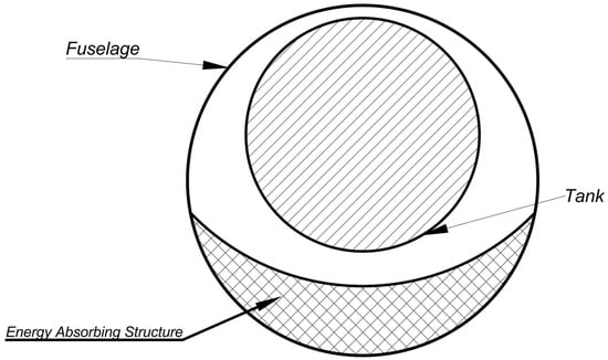
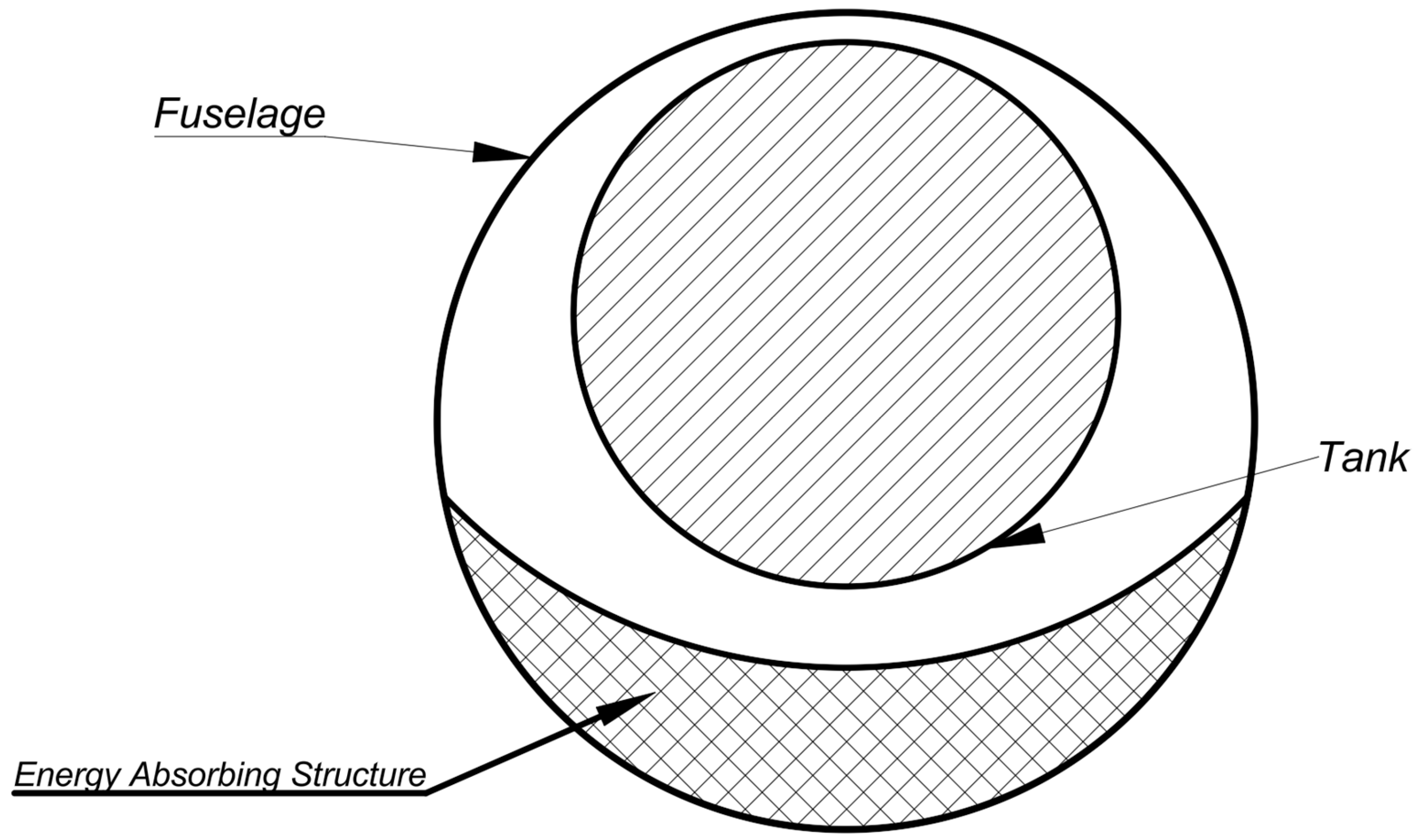
To address these safety considerations, the positioning of the tank within the fuselage is critical. In the proposed concept, the upper side of the fuselage frames area was selected, in order to avoid direct mounting of the tank on the lower fuselage side, which undergoes excessive deformation and failures in the critical situations of an emergency landing or crash. This leads to the mounting of the hydrogen tank on the upper fuselage area, suspending it from its upper side. Due to the difference in diameter between the fuselage and the tank, and the eccentric upwards offset installation, a clearance between the tank and the lower fuselage elements is created. This space allows for adequate fuselage deformation during impact or crash landing scenarios and provides sufficient volume for the introduction of energy-absorbing structures below the tank, thereby enhancing crashworthiness, as illustrated in Figure 1.
Figure 1.
Schematic representation of eccentricity between the tank and the fuselage.
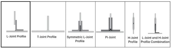
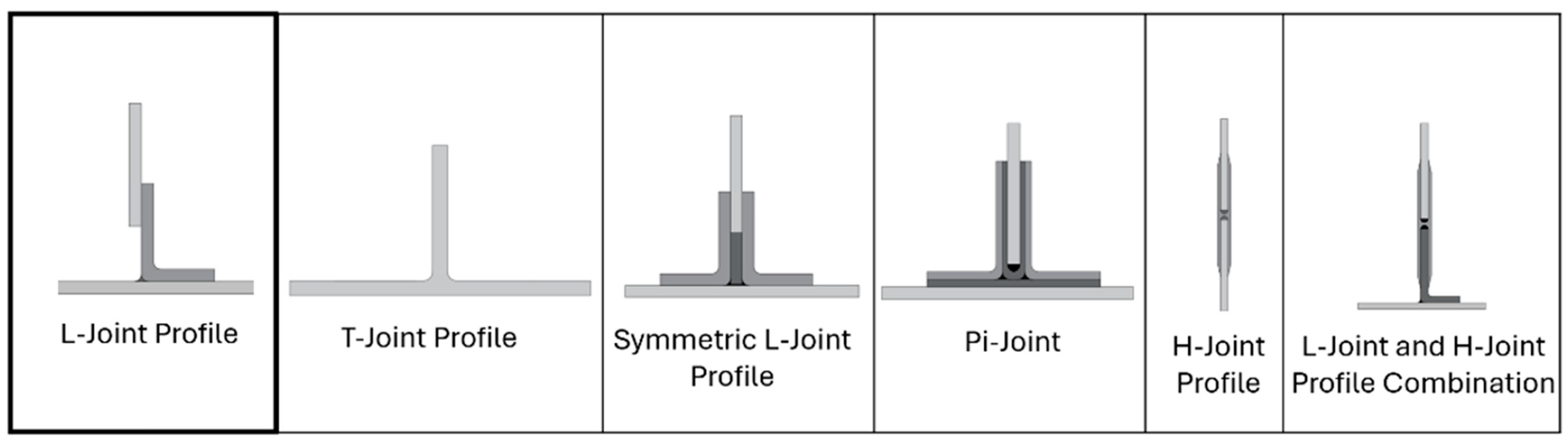
With respect to the selection of joining elements, an efficient integration concept must employ joints that minimize stress concentrations into both the fuselage and the tank, while limiting thermal conduction into the tank. In this frame, and to address structural integrity and damage tolerance requirements, bonded joints are proposed and investigated as the primary load transfer elements. Given the known limitations of bonded joints, particularly their susceptibility to debonding under peel or normal loading, appropriate joining geometries were selected that redirect the load path, such that the bondline is predominantly loaded in shear. Various alternative joint geometries, such as those illustrated in Figure 2, have been previously investigated for aeronautical applications, e.g., [21]. Based on an initial analysis and the current application requirements, the L-joint type was initially identified as the more suitable and was adopted for the proposed integration system.
Figure 2.
Schematic representation of the considered bonded joint profiles, L-profile selected.
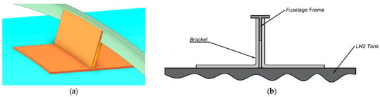
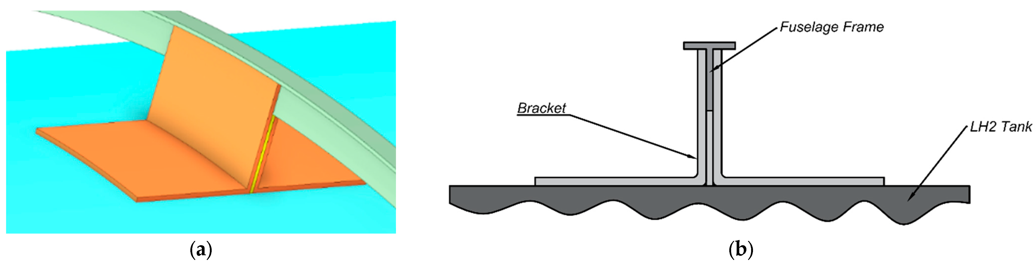
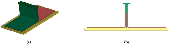
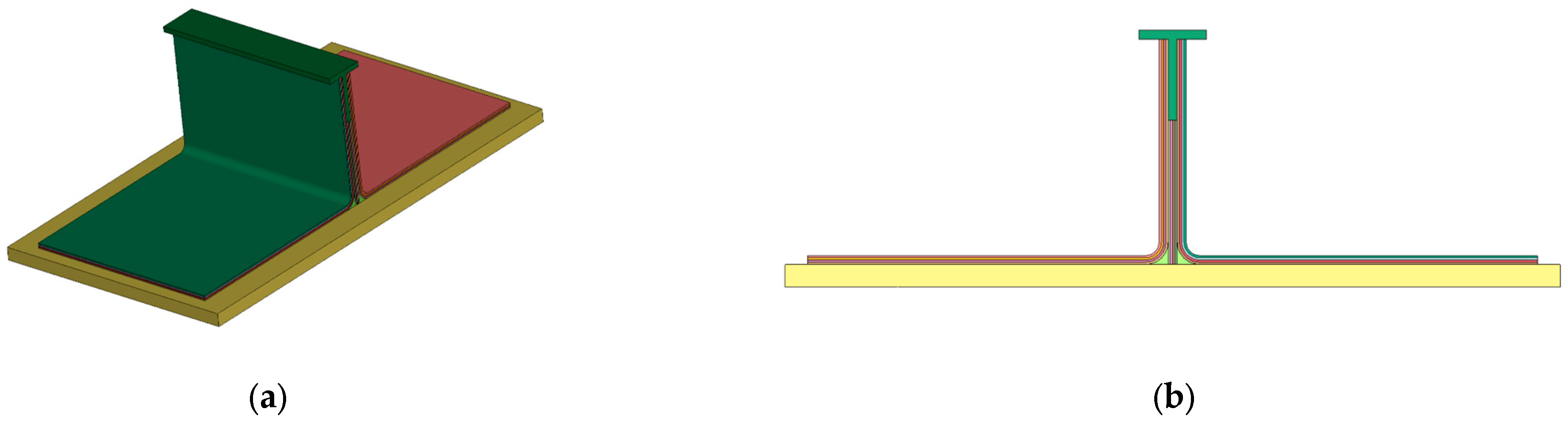
As mentioned prior, to enable the attachment of the tank to the upper crown of the fuselage, shear loaded adhesively bonded joints are investigated. Adhesive bonding is selected over mechanical joints to reduce stress concentrations. High-performance cryogenic tanks are usually constructed from laminated composites, as are most modern aircraft fuselages, to achieve a higher strength to weight ratio. Laminated composites are susceptible to delamination and bearing type failures when connected via mechanical fasteners. Adhesive bonding provides a uniform distribution of the load over a larger area, minimizing the risk of damage to these materials, providing a higher level of damage tolerance, an essential aspect of attaching the highly sensitive composite cryogenic tanks. To mitigate the risk of disbond under normal loads, shear loaded joints providing a more reliable connection are selected. The joint geometry that was selected was double symmetrical L-joints. The lower, horizontal flange of the joints is bonded to the outer surface of the tank, while the vertical flange is bonded to the faces of the frames, which provide adequate rigidity and strength to receive the loads exerted by the tank’s mass. Figure 3 illustrates the examined structural integration approach. Attaching the tank from the top of the fuselage significantly reduces the risk of the structural integrators penetrating the tank, as would be the case with attaching the tank to the bottom of the fuselage, since under high loads, detachment of the brackets is expected.
Figure 3.
(a) Structural integrator isometric view (fuselage frame, tank and brackets colored in green, cyan and orange/yellow respectively), (b) structural integrator sketch side view.
Selection of materials for the proposed mounting concept was performed based on applicability as well as meeting the specific demands of the concept’s components. The materials used for the structural components of the fuselage—tank interfaces are summarized in Table 1. These materials have been selected due to their relevance to aerospace applications and their well-documented mechanical behavior in the existing literature. AS4 carbon fiber reinforced PEEK thermoplastic matrix was used in the fuselage barrel section. Compared to thermoset composite materials, the internal semicrystalline structure of thermoplastics leads to improved fatigue [22,23] and impact damage tolerance [24,25,26,27,28]. Non-Crimp Fabric (NCF) T700 carbon fiber reinforced RTM6 resin was used for the tank—fuselage structural interfaces. High out-of-plane mechanical performance is required in applications such as brackets; therefore, NCFs composites have been selected, as acceptable materials in such applications, as is demonstrated in [29,30,31,32].
Table 1.
Mechanical properties of the materials used.
Provided that the main objective of the present study is to assess the structural response and restraint effectiveness of different integration configurations rather than to perform their detailed design, the material modeling was kept simple; thus, the post-failure behavior (material plasticity and failure) were not modeled, which however, did not prevent the comparison between the different variations in the structural integration approach, and the drawing of conclusions regarding the most promising configurations of the proposed concept.
Perfect bonding conditions were assumed at all interfaces of the global model. Debonding and interface failure at global geometry level will be considered in future studies using more detailed tank and fuselage geometries. For the Cohesive Zone Modelling (CZM), FM300 film adhesive properties were used, since it is widely used in the aviation sector, both civilian and military. The performance of the adhesive is reported under a wide range of conditions, i.e., static in [35,36], fatigue in [37] and under hot and humid environments in [38,39]. The properties used for the CZM analysis are presented in Table 2.
Table 2.
Mechanical and fracture properties of FM300 film adhesive.
Structural integration systems for onboard energy storage must withstand not only normal operating loadings, but also those arising from other scenarios, such as emergency landings and crash events. According to EASA CS-25.561 and CS-25.963 [40], large transport aircraft must satisfy prescribed inertial load requirements in the forward, rearward, upward, downward, and lateral directions. These inertial loads were considered as the most critical loads that drive the design, while aerodynamic and ground loads have already been considered in the fuselage structural design. For the present analysis, rearward acceleration was not considered due to the geometric symmetry of the model and its relatively low magnitude (1.5 g) compared to the forward acceleration case (9 g). This load case will be included in future studies as the model evolves toward a more detailed fuselage geometry to ensure completeness. The load cases presently examined are presented in Table 3.
Table 3.
Static inertial load cases examined.
Having conceptually designed the mounting system, the effects of its main parameters on the structural response of the fuselage frames and the tank shell are studied in the following sections.
3. Development of Parametric Simulation Model of the Mounting System
3.1. Model Geometry
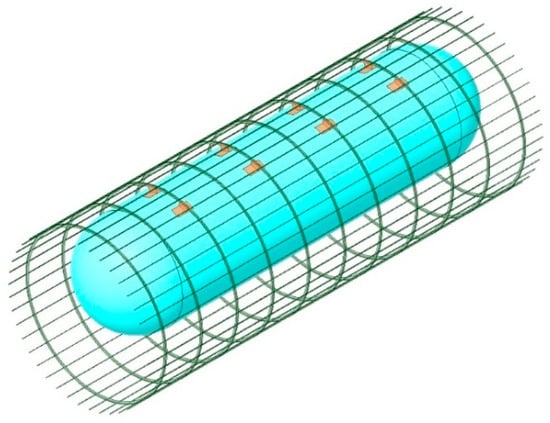
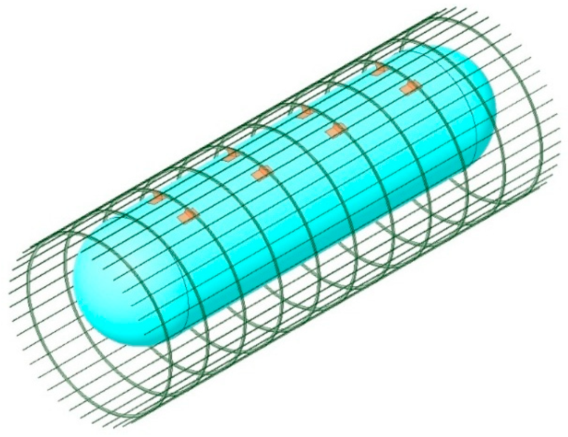
A fuselage barrel section representative of a regional or commuter-class aircraft was modeled to investigate the critical design features of the proposed tank integration concepts, illustrated in Figure 4. The primary response quantities of interest include load distribution within the structural integrators, stress levels in fuselage components, and the stress and displacement response of the tank.
Figure 4.
Isometric view of the geometry examined.
3.1.1. Fuselage Section
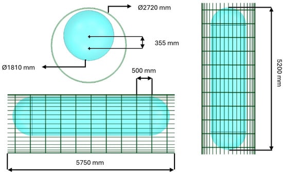
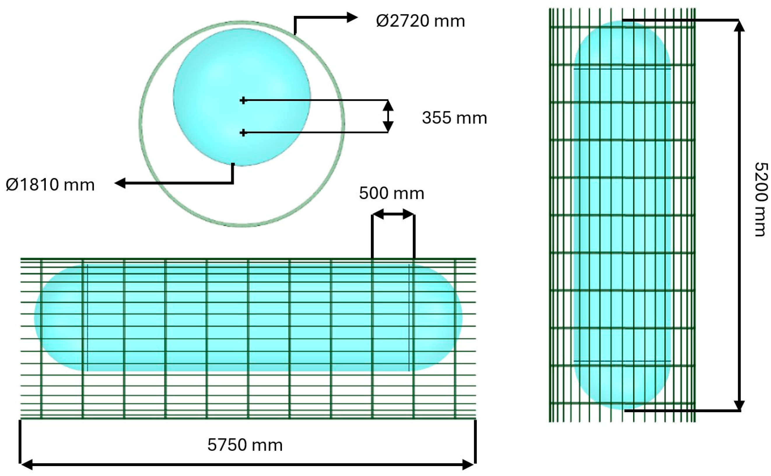
A circular fuselage cross-section representative of a regional aircraft was selected for this study. The resulting structural behavior is expected to be representative of more complex fuselage configurations under the examined loading conditions. Details for the fuselage barrel section are presented in Table 4. The primary dimensions are also illustrated in Figure 5.
Table 4.
Fuselage barrel section details.
Figure 5.
Fuselage and tank primary dimensions.
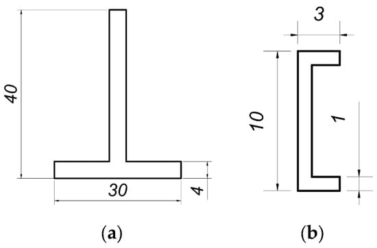
The fuselage section includes forty C-shaped stringers evenly distributed along the circumference, corresponding to an angular spacing of 9°. These stringers provide longitudinal stiffness and facilitate the transfer of axial loads along the fuselage. Their dimensions are listed in Table 5.
Table 5.
Stringers’ geometrical details.
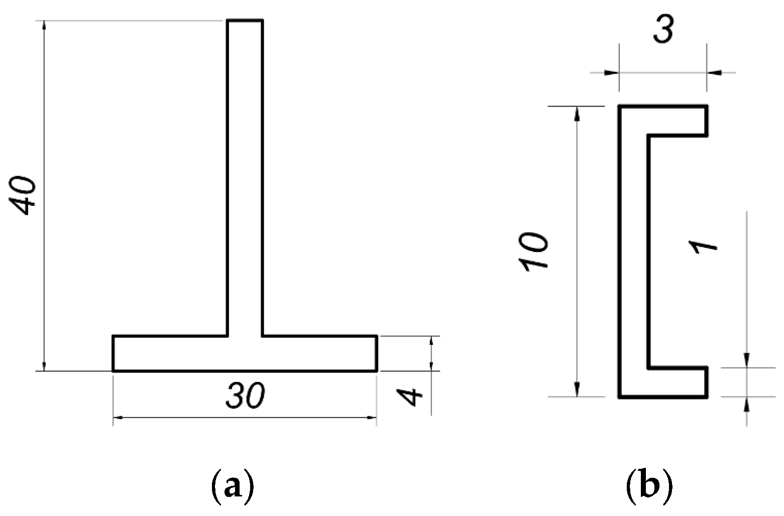
The fuselage frames were modeled using a T-shaped cross-section to facilitate attachment of the support brackets. This representation provides sufficient fidelity to capture load paths and deformation behavior, and the results are expected to be transferable to more detailed frame geometries. The geometric details of the frames are presented in Table 6. Sketches with the frames’ and stringers’ profiles are presented in Figure 6.
Table 6.
Frames’ geometrical details.
Figure 6.
(a) Frames’, (b) stringers’ profiles.
3.1.2. LH2 Tank
Independent vacuum-insulated LH2 tanks typically consist of two concentric shells—an inner pressure vessel and an outer shell—connected by thermally efficient supports designed to minimize heat transfer. As the detailed internal structure and insulation system are beyond the scope of the present work, the tank walls were modeled with increased thickness relative to practical designs. Similarly, the pressure of the inner tank is typically between 3 and 6 bar, however this pressure does not have a significant effect on the outer shell that is modeled presently. The selected approach reduces the likelihood of localized buckling, wrinkling, or unrealistic stress concentrations.
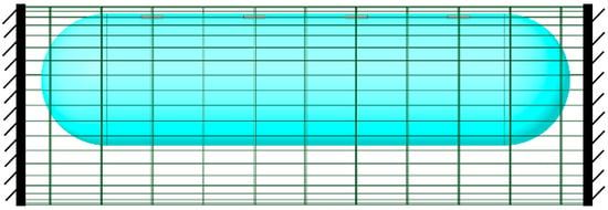
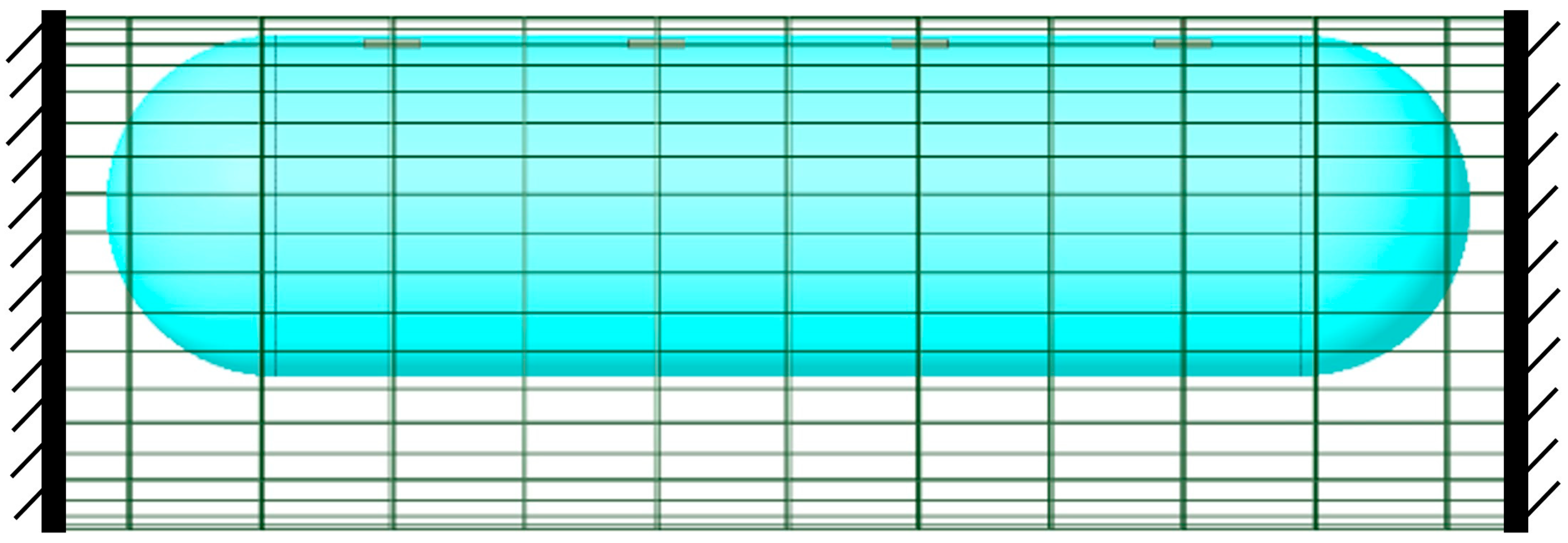
The tank is positioned eccentrically within the fuselage, with its center located 355 mm above the fuselage centerline. This offset was selected to allow for crashworthiness tolerance and has a direct influence on the structural response, particularly under longitudinal and lateral inertial loading. The dimensions of the tank are presented below in Table 7 and have been selected as representative of a regional aircraft LH2 tank. The total mass of the tank is 1100 kg. This mass is derived by an assumption of 600 kg of fuel mass, plus an additional 300 kg of systems, in addition to the mass of the tank’s structure. The tank was modeled as a deformable cylindrical shell with hemispherical end caps. Internal stiffening structures, commonly used in practice, were not explicitly modeled.
Table 7.
Tank geometric details.
3.1.3. Tank—Fuselage Structural Interface Concept
The interface brackets proposed in the present work consist of L-shaped joints and are symmetrically attached to both the fuselage frames and the tank. Given the T-shaped profile of the frames, symmetrical L-joints provide consistent load transfer characteristics. Hereafter, the structural integration components will be referred to as brackets, with each bracket consisting of two L-joints. The dimensions and characteristics of the structural integrators are listed in Table 8.
Table 8.
Structural integrator geometric details.
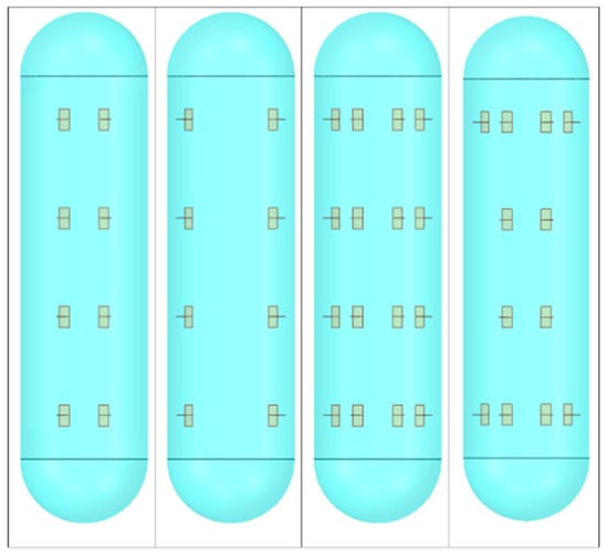
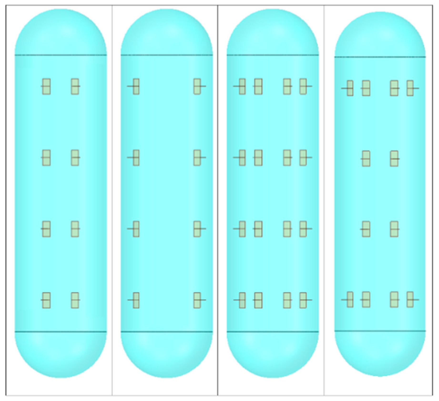
Four integration configurations were parametrically investigated based on an initial estimation of the expected load distribution:
- Configuration A: Eight brackets attached to the frames from the top.
- Configuration B: Eight brackets attached from the top at a wider angular spacing.
- Configuration C: Sixteen brackets combining Configurations A and B.
- Configuration D: Twelve brackets similar to Configuration C, excluding four outer brackets near the mid-length of the tank.
The additional mass for the installation of the LH2 tank structural integrations configurations is presented in Table 9.
Table 9.
Installation mass for the four configurations.
The representative geometry and bracket layouts for each configuration are illustrated in Figure 7.
Figure 7.
The four configurations examined.
Expected advantages and disadvantages of the four configurations are presented in Table 10.
Table 10.
Advantages and disadvantages of the four configurations examined.
3.2. Finite Element Modeling Details
The analyses performed were quasi-static and no sloshing or similar dynamic phenomena were considered. Similarly, in this work, emphasis was placed on the mechanical aspect of the integration, and therefore no thermal phenomena were simulated. Heat insulation design aspects are primarily considered during the design of the cryogenic tanks, which is beyond the scope of the present work. Due to the tank thermal insulation, investigation of the bonding behavior under such temperature gradients is not required in the present study. Similarly, hydrogen embrittlement due to hydrogen permeation is not considered, because the structural integrators between the tank and the fuselage are not in contact with the fuel nor in its proximity. The simulations of the LH2 tank integration scenario into the fuselage barrel section were performed using ANSYS Workbench 2025R1 with the Mechanical APDL solver. The geometry was developed in SpaceClaim, enabling parameterization for efficient geometric modifications. The geometry was then imported into ANSYS Mechanical, where material properties, ply orientations, and laminate definitions were assigned.
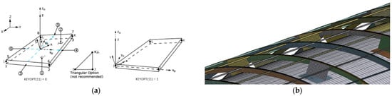
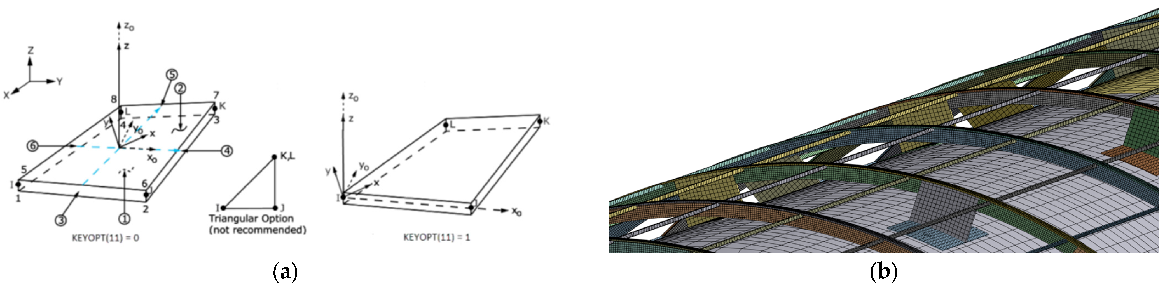
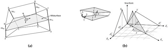
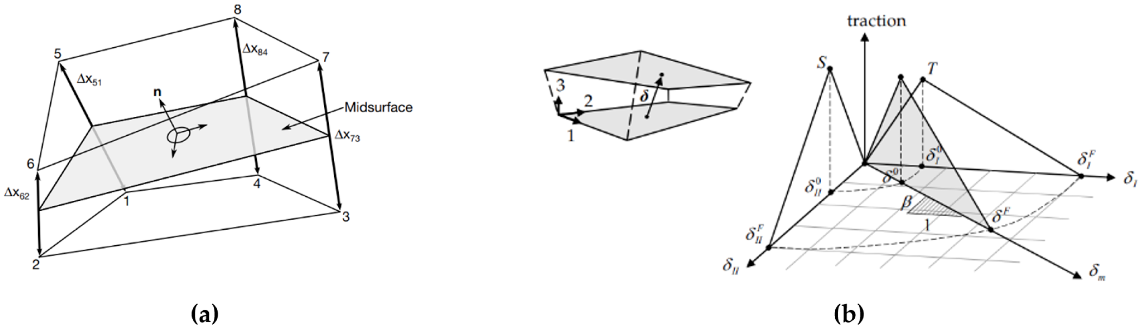
SHELL181 elements were employed for all shell components. To ensure that the numerical results were independent of the mesh density, a mesh convergence study was performed setting the convergence criterion to 2.5% difference in node displacements between the iterations; as a result, an element size of 10 mm was selected for the structural integrators and the stringers, 5 mm for the frames and 50 mm for the tank and the fuselage skin, providing accurate stress predictions, while avoiding numerical singularities and maintaining reasonable computational cost. A figure of the shell elements formulation [41] as well as the model’s element discretization is displayed in Figure 8.
Figure 8.
(a) SHELL181 element formulation, (b) model element discretization.
Contact definitions, boundary conditions, and inertial loads were subsequently applied. The additional mass of the tank was input as a distributed load on the inner surface of the tank. The fuselage barrel section was fixed at both ends, and inertial loads were applied to the entire assembly as illustrated in Figure 9. No additional loads were considered, as the modeled section is located aft of the rear pressure bulkhead within an unpressurized compartment.
Figure 9.
Finite element model boundary conditions.
The mechanical response of the four configurations was evaluated by examining the state of the structural integrators, their effect on the tank and on the fuselage. The reaction forces of the structural integrators, the load distribution as well as their stress distribution were analyzed to examine whether each configuration can effectively carry the loads. The effect of the structural integration approach on the tank was investigated by examining the stress distribution and the displacement and deformation of the tank, while the effect on the fuselage was analyzed by the stress distribution on the frames and the stringers.
3.3. Component Level Cohesive Zone Modeling
Following the global analyses, component-level CZM was performed on selected critical brackets, to assess the potential for debonding. Critical brackets were identified as those experiencing the highest normal and shear loads in the global model.
The local debonding analyses were conducted using LS-DYNA R8, due to its flexibility in switching between implicit and explicit solution schemes when convergence issues arise. In explicit analyses, care was taken to minimize dynamic effects and ensure that kinetic energy remained negligible relative to internal energy.
At the component level, brackets were modeled using constant-stress solid elements (ELFORM_01), while the adhesive layer was represented using four-point cohesive elements (ELFORM_19) [42] with a bilinear traction–separation law (MAT_138) [43]. A schematic of the element formulation and constitutive behavior is provided in Figure 10.
Figure 10.
(a) Cohesive element formulation in LS-DYNA [42]. (b) Bilinear traction–separation material model [43].
Boundary conditions were applied such that the upper end of the model was fixed, while the load extracted from the corresponding global analysis was applied on the bracket, illustrated in Figure 11.
Figure 11.
Component level model geometry (a) isometric view, (b) side view.
This multi-scale modeling approach provides a robust framework for evaluating structural integration concepts, identifying critical stress regions, and assessing the relative performance of different configurations under representative inertial loading conditions.
4. Concept Variations Results and Discussion
In the present analyses, emphasis is placed on the relative performance of the four alternative configurations rather than on absolute stress or displacement values. In certain cases, as prefaced, high stress values beyond the strength of the materials might be observed due to lack of damage modeling. Given the nature of this investigation as a feasibility study, comparing different configurations is still possible even with this limitation. In next studies, enhancement of the representative geometry will yield more realistic results via optimization and more detailed design, bracket resizing or local reinforcement of the components involved.
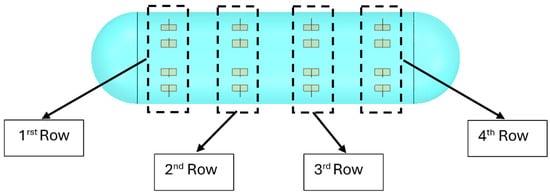
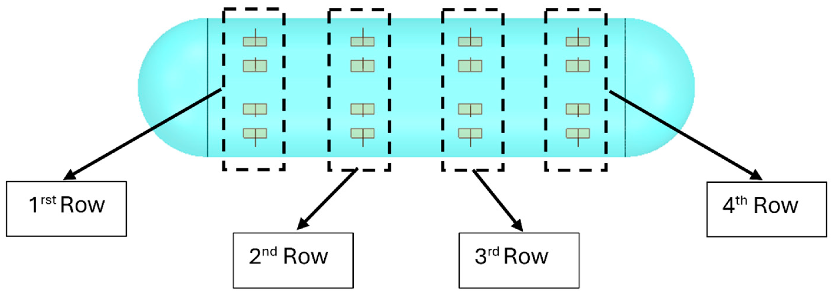
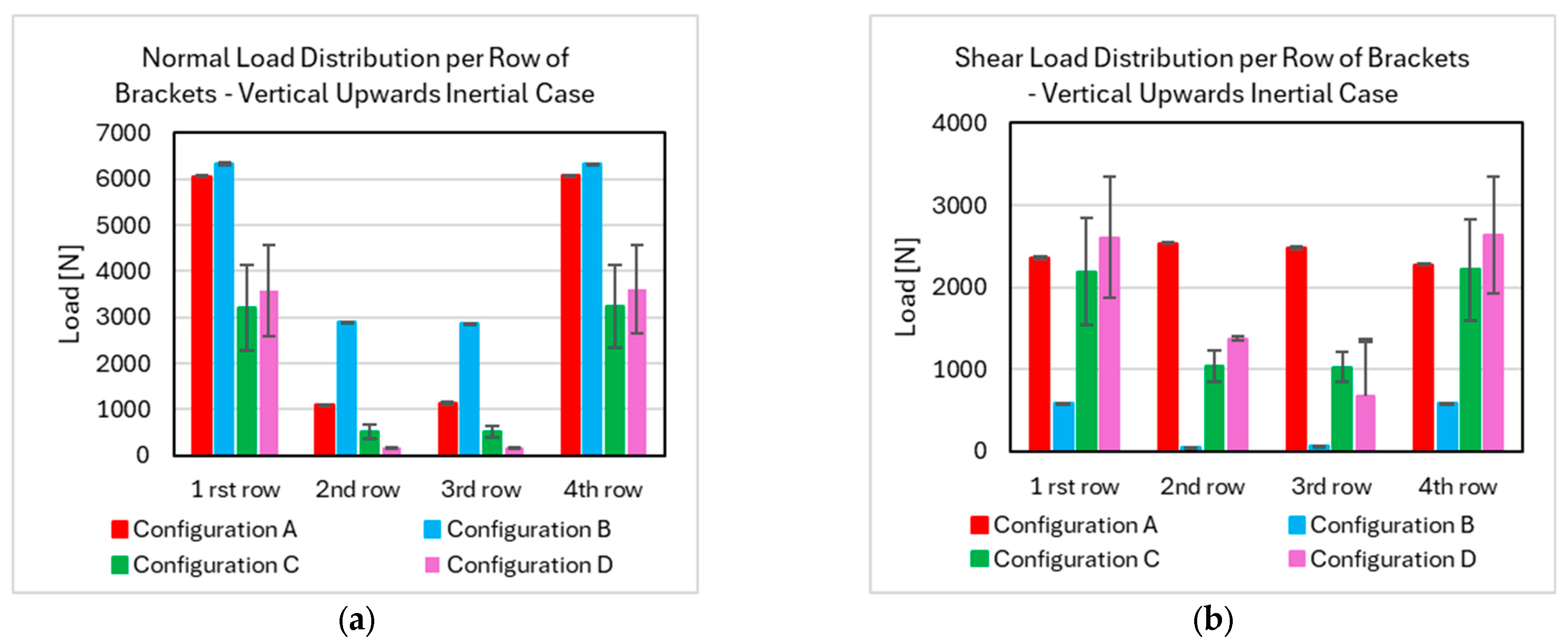
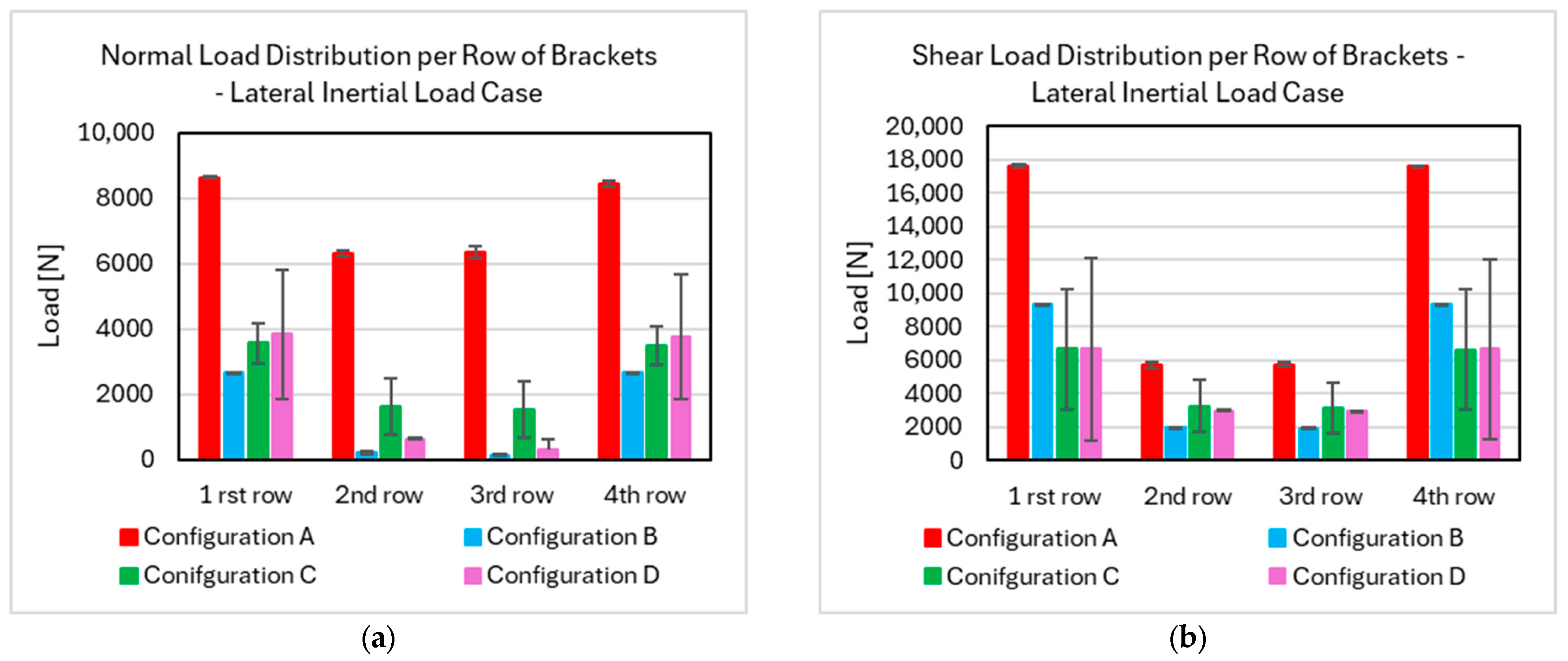
The following results compare the mechanical response of the structural integrators and their effects on the tank, fuselage frames and stringers. More specifically, the presented magnitudes include load distribution and stress levels in the brackets, tank displacement and stress, and stress on the fuselage barrel section. Bracket loads are grouped into four categories according to their position, as illustrated in Figure 12. In the load distribution bar charts that follow, the primary bars represent the average load within each group, while the secondary black bars indicate their minimum and maximum values.
Figure 12.
Grouping of structural integrators.
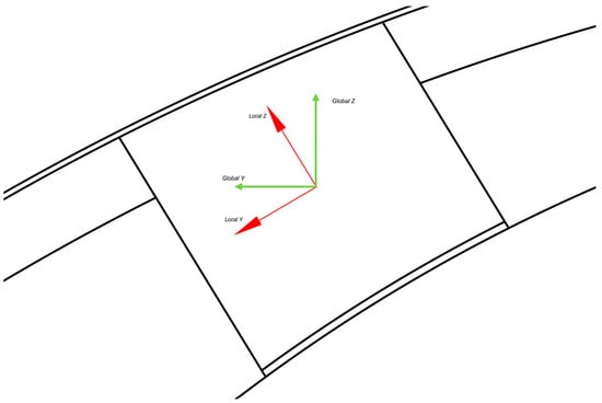
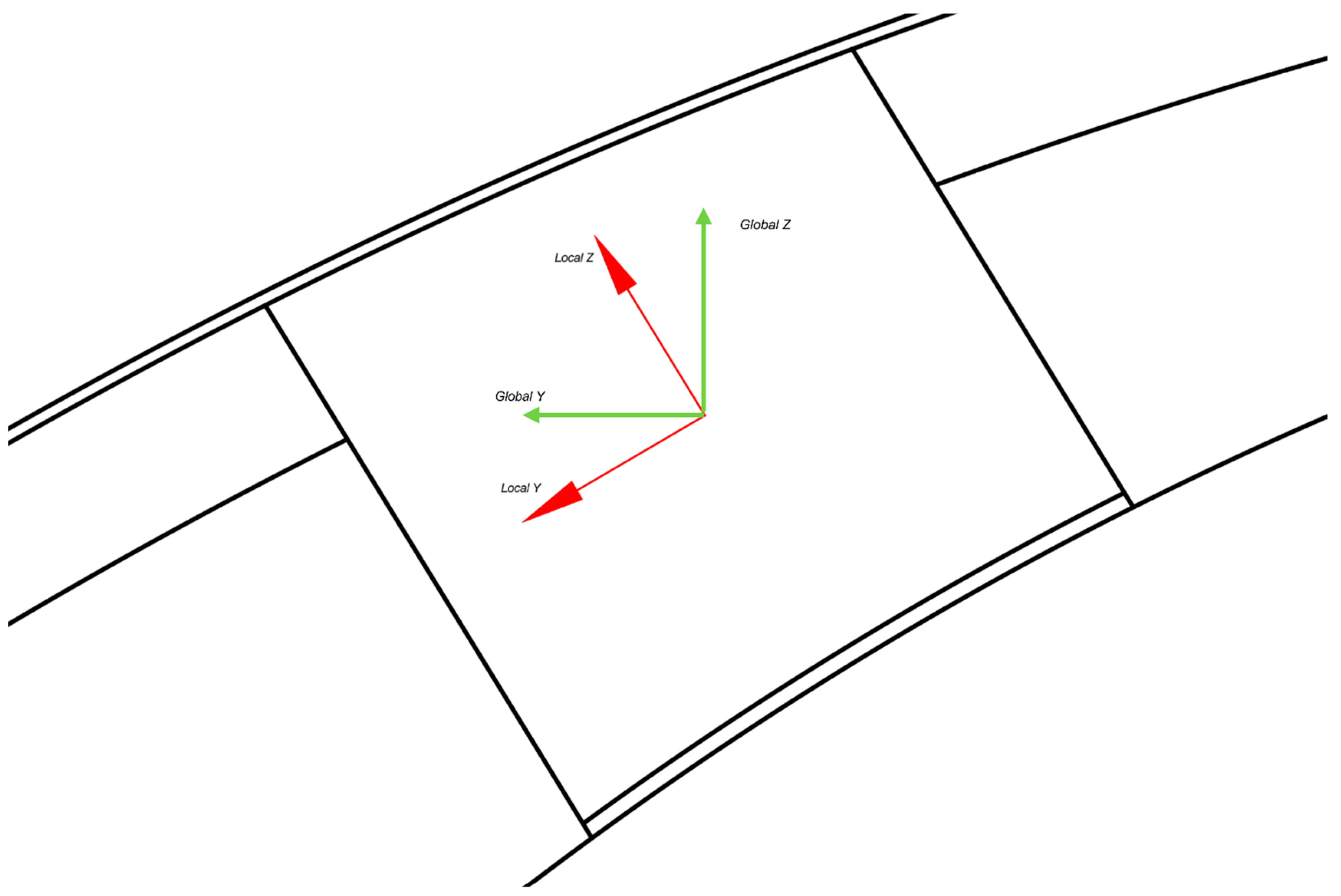
For the vertical and lateral inertial load cases, loads were transformed into a local coordinate system for each bracket. Loads acting normal to the tank surface were extracted to evaluate normal (peel or compressive) loading, while transverse components were used to assess shear loading, as illustrated in Figure 13. Results are presented on a per-load-case basis, with the primary objective of assessing the applicability and performance of each structural integration configuration.
Figure 13.
Transformation of force reaction on structural integrators from global (green) to bracket (red) coordinate system.
4.1. 9 g Forward Acceleration Introduced as Static Inertial Load
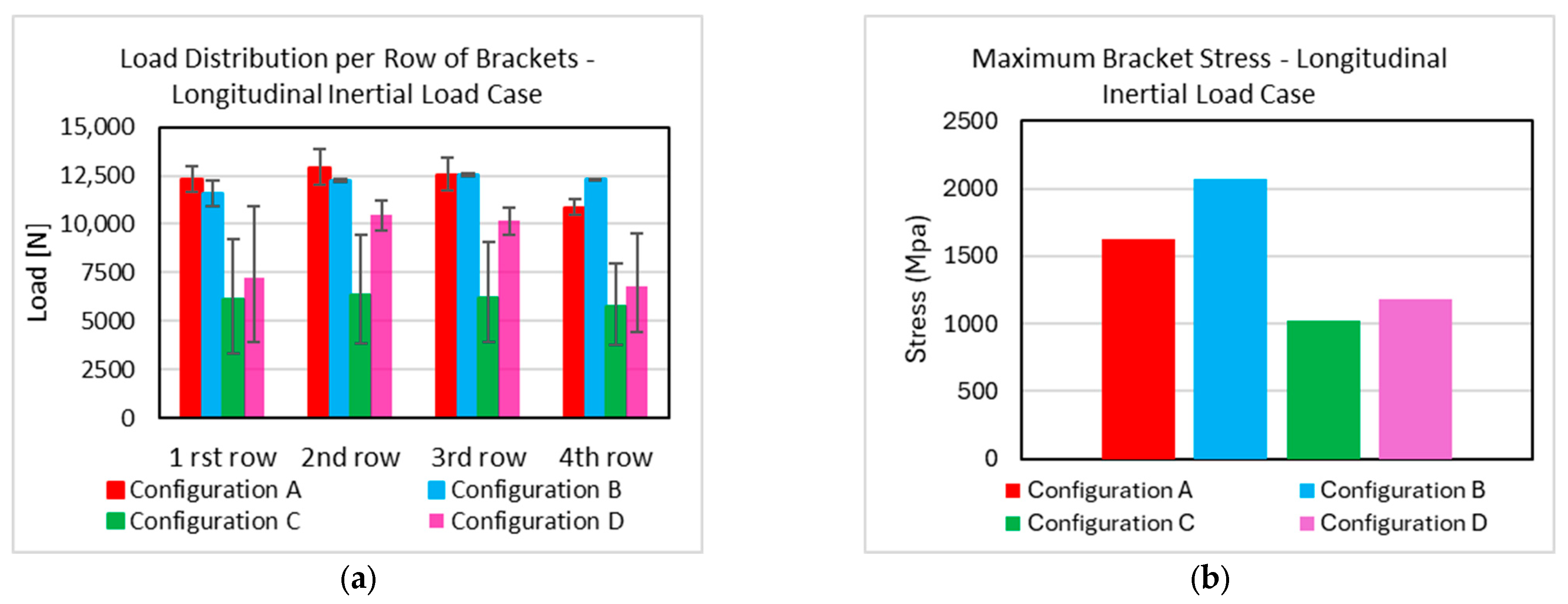
The forward acceleration case represents the most critical loading scenario due to the high inertial forces involved. Analysis of the longitudinal reaction forces on the brackets, presented in Figure 14a indicates that configurations with a higher number of brackets result in a more uniform load distribution. Under this load case, adhesive bonds are most susceptible to debonding, particularly in regions where load transfer induces bending in the brackets between the fuselage frames and the tank attachment points.
Figure 14.
Longitudinal inertial load case, (a) longitudinal load distribution among the brackets for the four configurations per row of brackets, (b) peak stress on the brackets.
Across all configurations, a consistent load distribution pattern is observed; brackets located near the upper region of the tank experience higher loads than those positioned closer to the sides. This behavior is attributed to the reduced compliance of the upper brackets, which have shorter effective lengths due to the eccentric placement of the tank relative to the fuselage centerline.
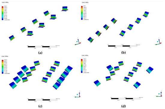
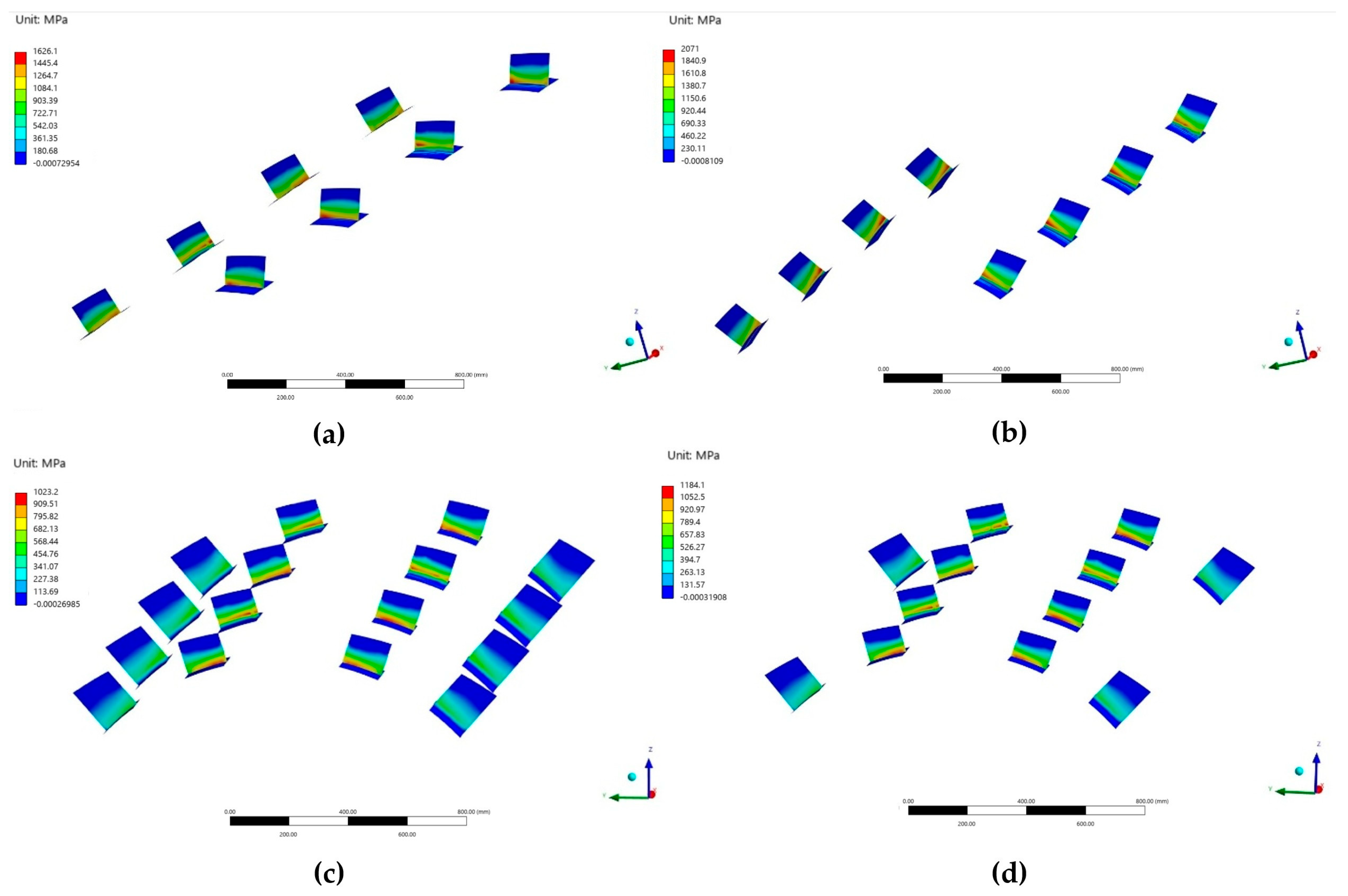
In Figure 15 the stress distribution on the structural integrators is presented. Configurations C and D exhibit more uniform stress distributions and reduced peak stresses in the brackets. In contrast, Configuration B displays the highest bracket stress levels, primarily due to increased bending associated with the longer bracket lengths resulting from the greater eccentricity between the tank and the fuselage.
Figure 15.
Longitudinal inertial load case—stress contour plot on the structural integrators for the four configurations.
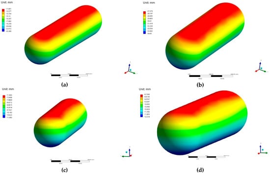
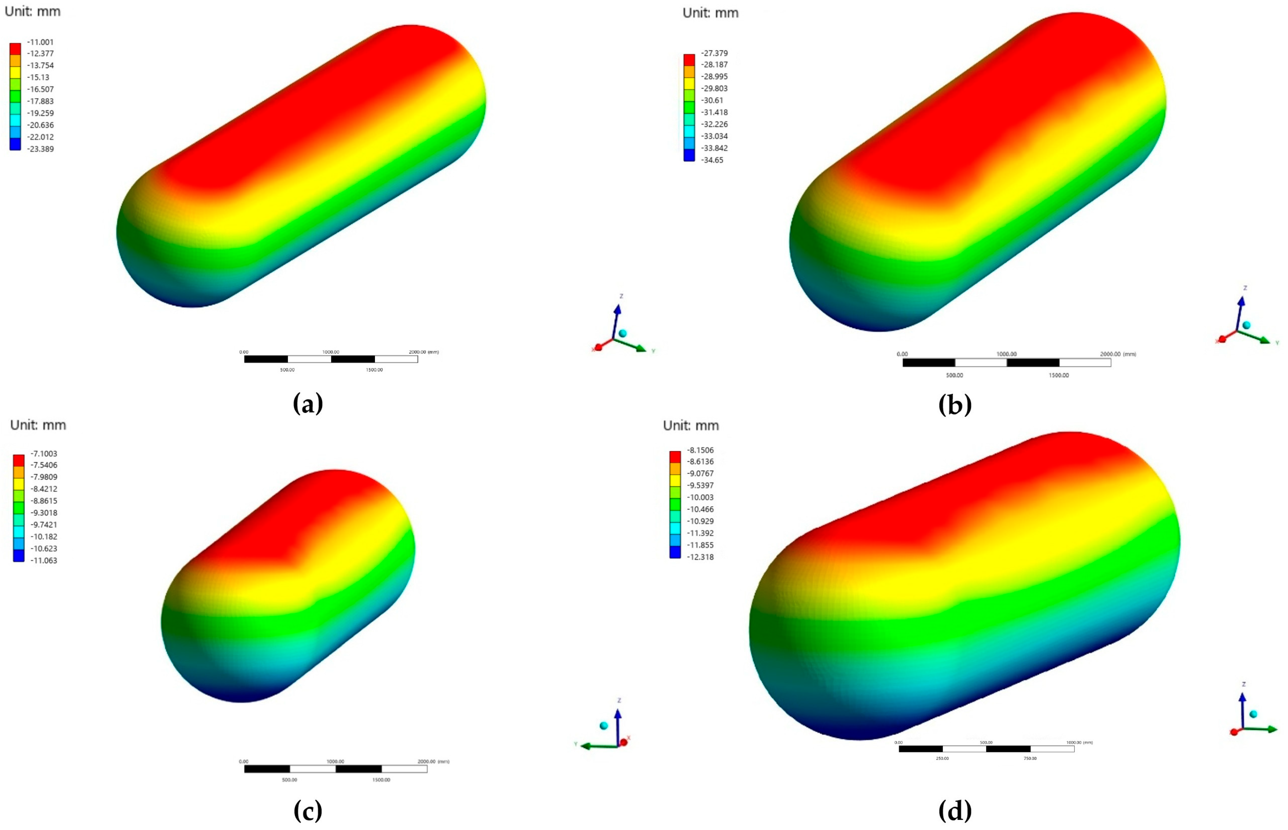
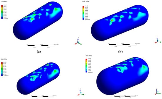
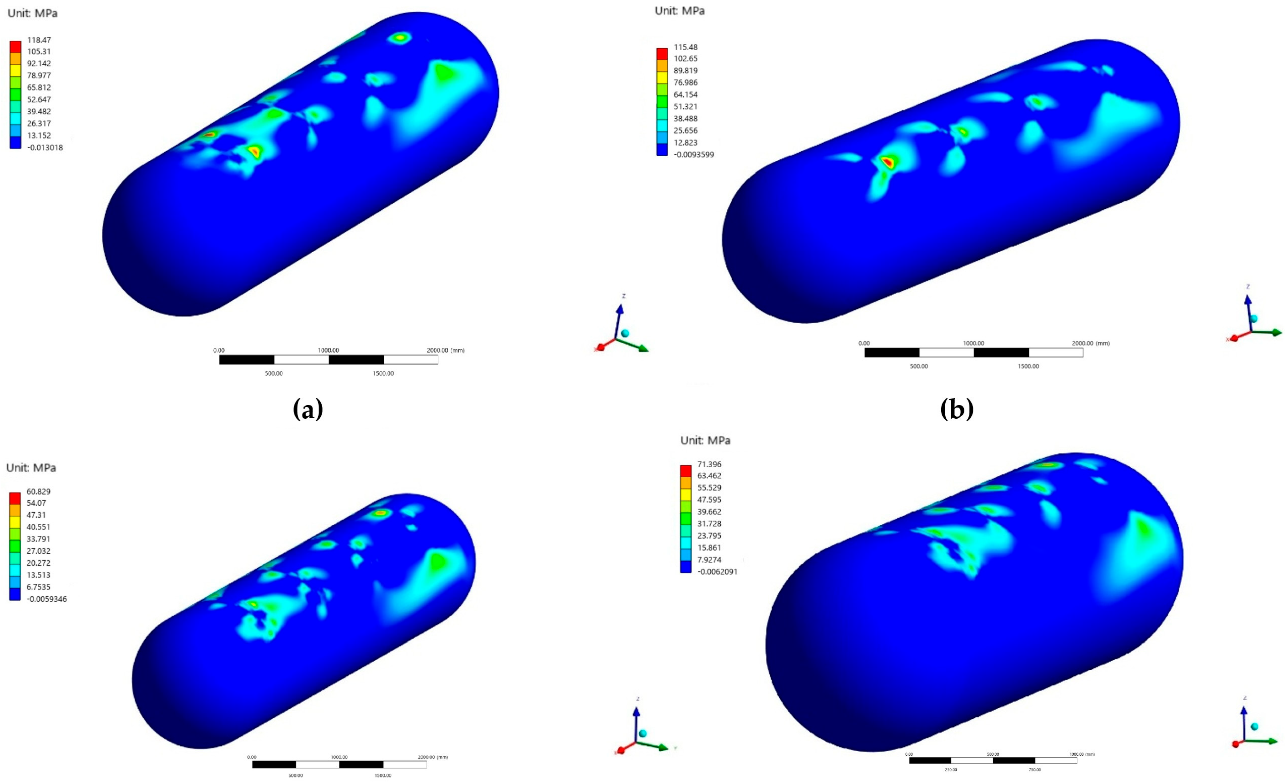
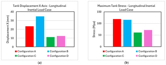
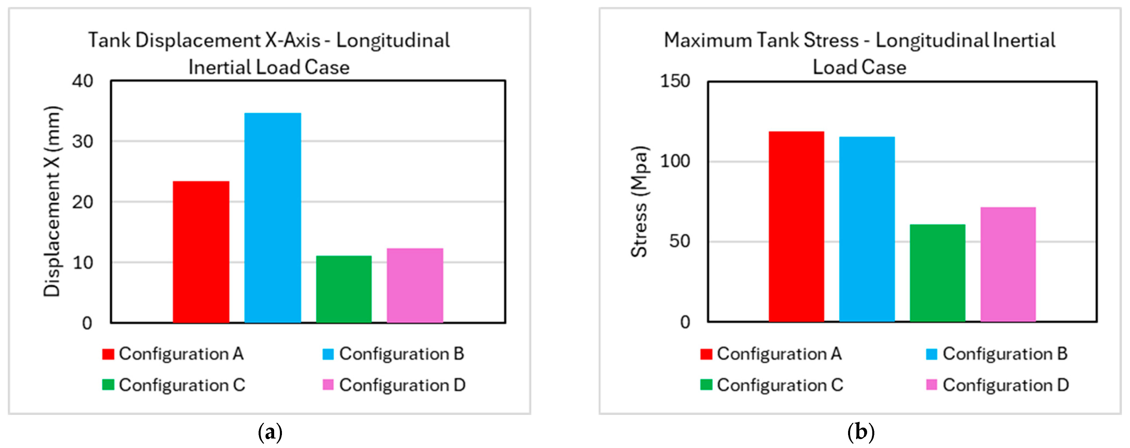
The tank displacement and deformation results presented in Figure 16 indicate that Configuration C provides the highest degree of restraint, with Configuration D yielding comparable performance. Stress levels on the tank, available in Figure 17, remain low for all configurations; however, Configurations A and B exhibit higher peak stresses and less uniform stress distributions compared to Configurations C and D. Both the peak tank displacement and the peak stress on the tank for each configuration are presented in Figure 18.
Figure 16.
Longitudinal inertial load case—tank displacement of the four configurations.
Figure 17.
Longitudinal inertial load case—tank stress of the four configurations.
Figure 18.
Longitudinal inertial load case, (a) maximum tank displacement, (b) maximum stress on the tank.
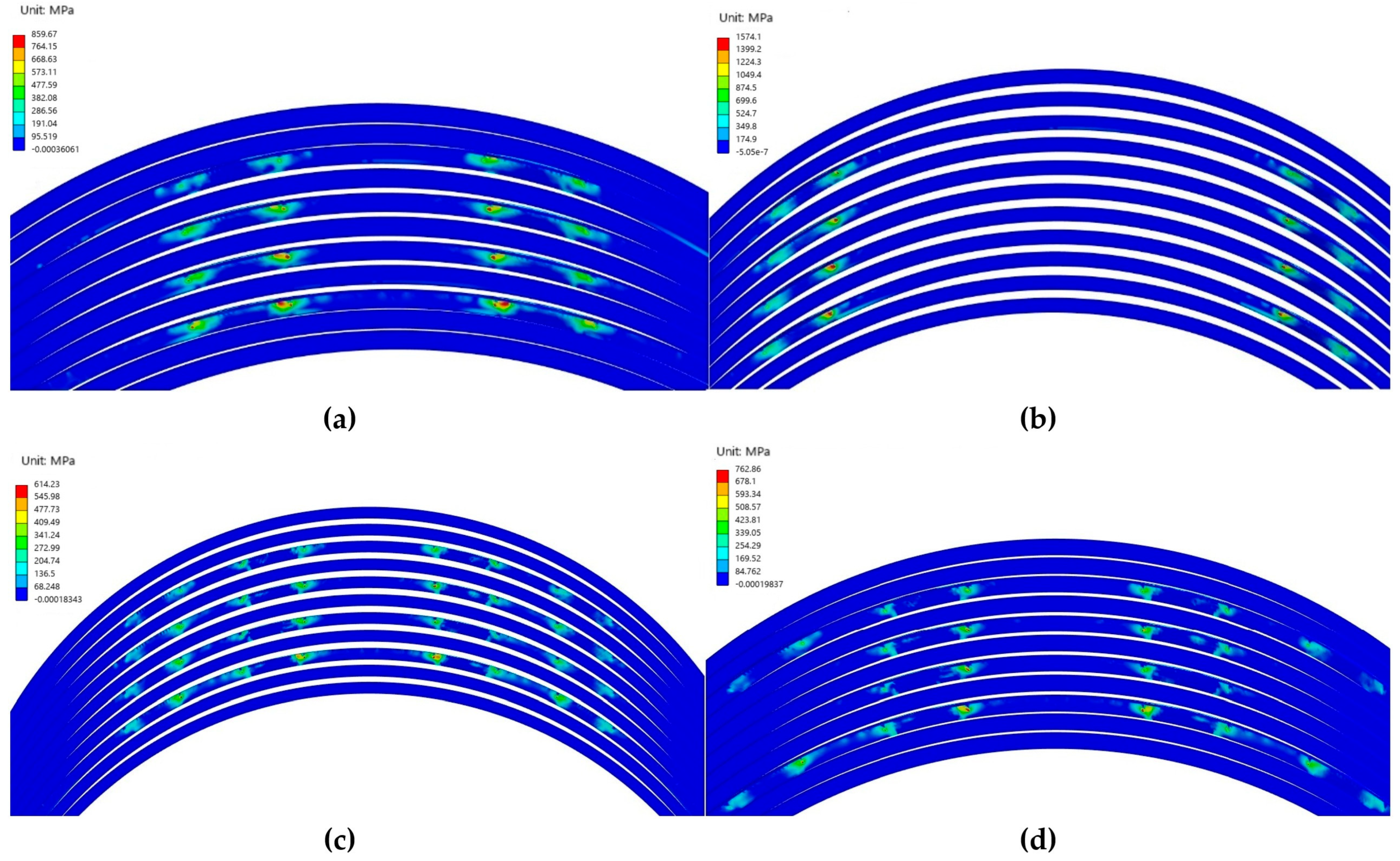
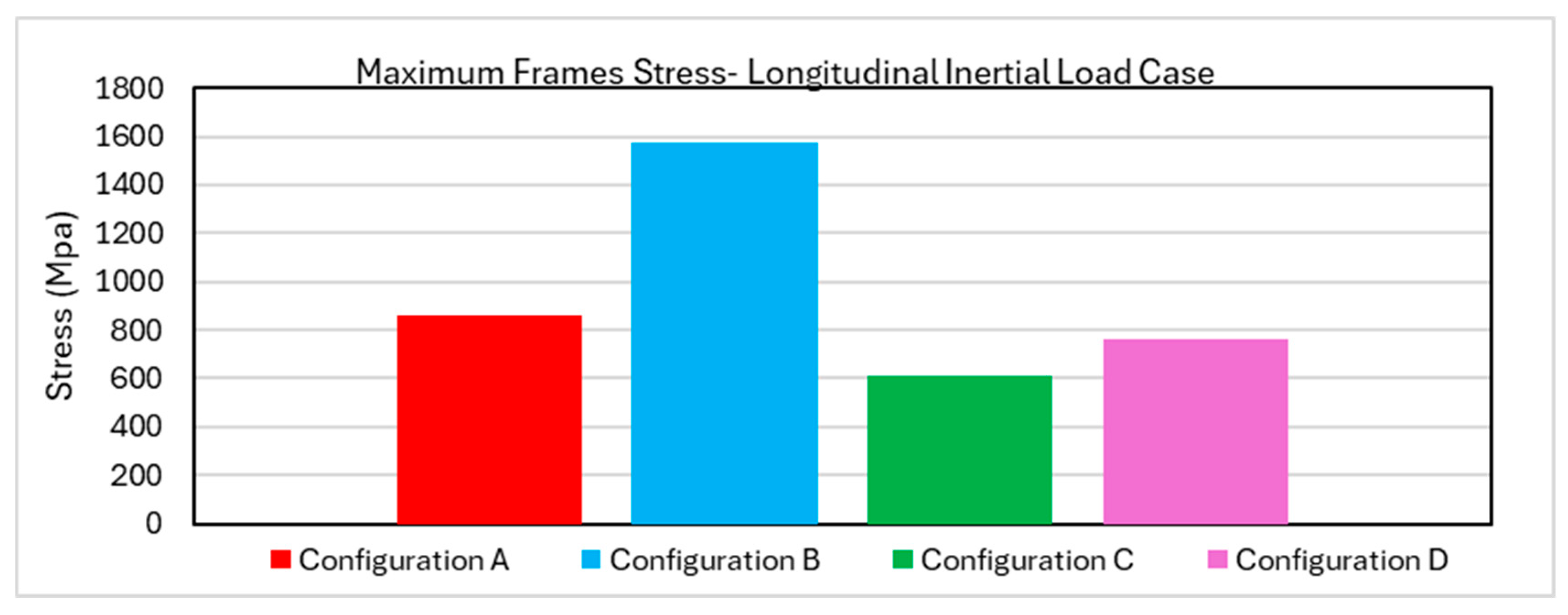
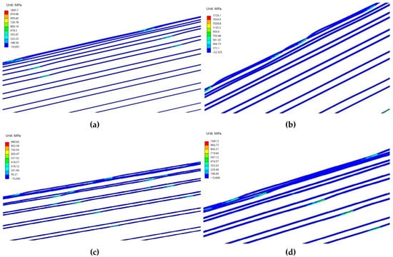
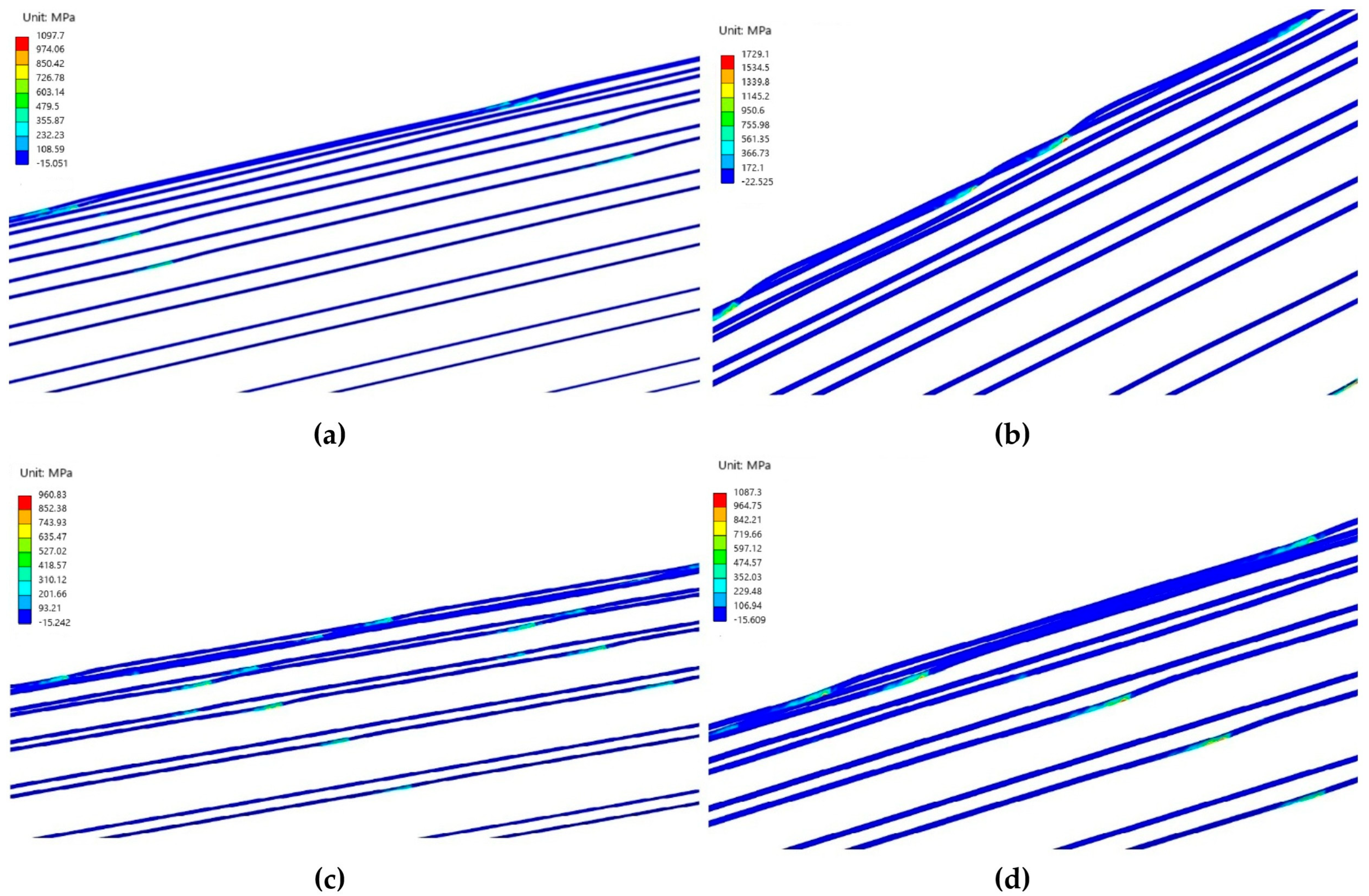
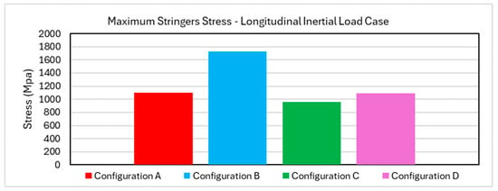
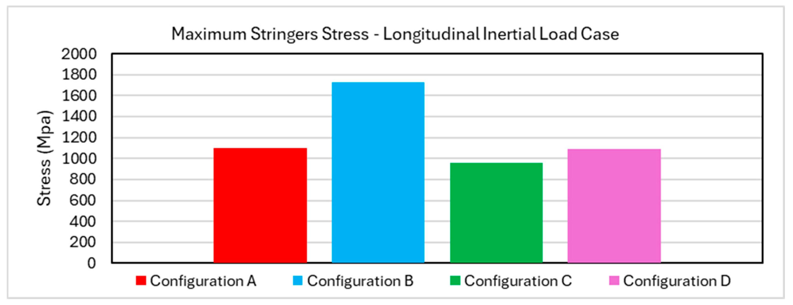
The fuselage response similarly benefits from distributing the load across a larger number of structural integrators. The results in Figure 19 indicate that stress levels in the frames remain low for Configurations A, C and D, while the maximum values are reported in Figure 20. Similarly, Figure 21 indicates that configurations A, C, and D result in significantly lower peak stress levels in the stringers compared to configuration B. The maximum stress in the stringers is presented in Figure 22.
Figure 19.
Longitudinal inertial load case—stress contour plot on the frames of the four configurations.
Figure 20.
Longitudinal inertial load case—maximum stress on the frames for the four configurations.
Figure 21.
Longitudinal inertial load case—stress contour plot on the stringers of the four configurations.
Figure 22.
Longitudinal inertial load case—maximum stress on the stringers for the four configurations.
Overall, the longitudinal inertial load case demonstrates that performance is primarily governed by the ability of the integration concept and fuselage longerons to effectively carry axial loads. The relatively high stress levels observed in this case are a consequence of the certification-required acceleration magnitude combined with the top-mounted tank support strategy. Configurations C and D displayed superior performance, while configuration A displayed good mechanical response for the fuselage but high stress levels for the brackets. The load level on the structural integrators will be further analyzed during the CZM analysis.
The stress distribution observed in the stress contour plots of this inertial load case was similar for the rest of the cases. Therefore, hereafter, the reader can refer back to the contour plots above while substituting the peak stress values reported in the bar charts. Any deviation in the observed mechanical response will be reported in each components’ accompanying description.
4.2. 6 g Downward Acceleration as Static Inertial Load
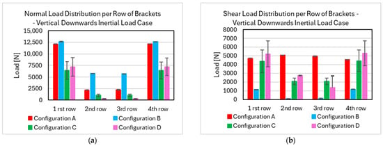
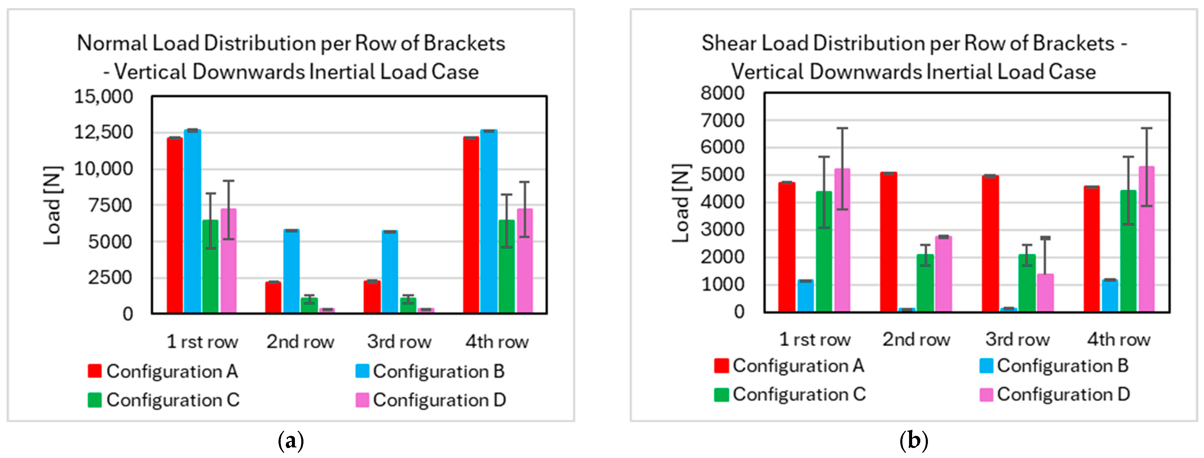
The 6 g downward acceleration case is also critical, as excessive normal loading could lead to debonding of the structural integrators and subsequent contact between the tank and the lower fuselage structure. Load distributions are examined in terms of both local normal (Z-axis) and transverse (Y-axis) components in Figure 23. The results indicate that Configurations C and D exhibit a more even load distribution among the brackets than Configurations A and B, owing to the increased number of load paths.
Figure 23.
Downward vertical inertial load case, (a) normal load distribution and (b) shear load distribution among the brackets for the four configurations per row of brackets.
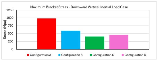
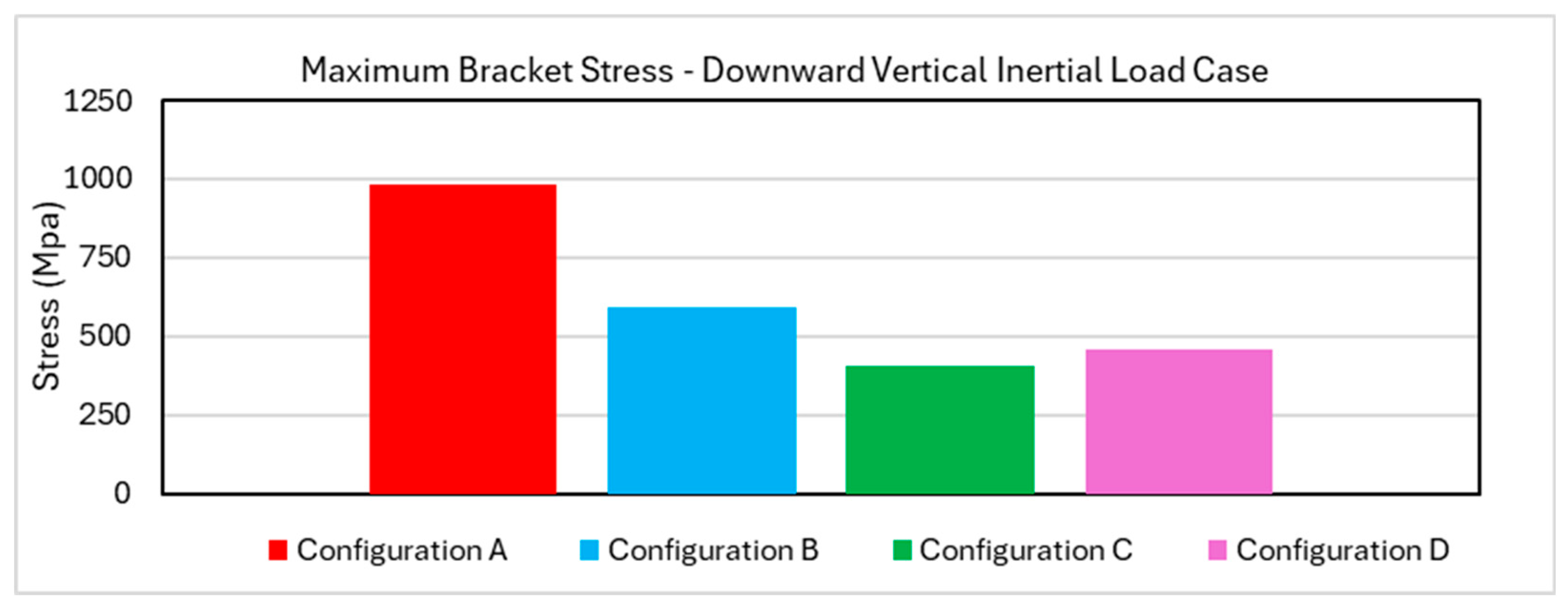
Brackets located near the mid-length of the tank contribute significantly less to load transfer than those near the tank ends, indicating that Configuration D performs comparably to Configuration C for this load case. Stress distributions in the brackets are relatively uniform for Configurations C and D, whereas Configuration A exhibits higher stress levels due to bracket orientation and proximity to the tank apex, as indicated in Figure 24.
Figure 24.
Downward vertical inertial load case—maximum stress on the brackets.
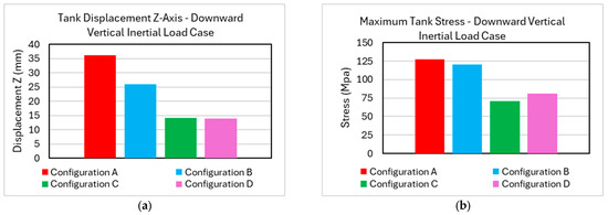
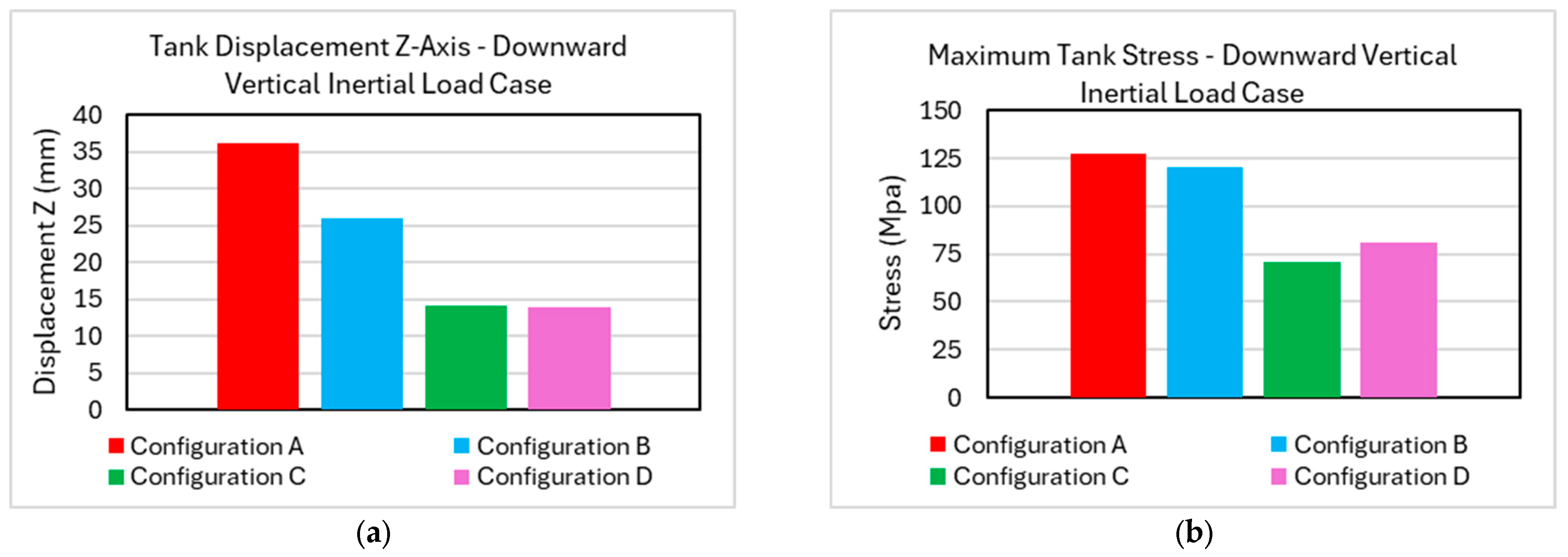
From Figure 25, it can be observed that increased bracket count results in lower tank stress levels and improved restraint. Configuration B demonstrates tank displacement lower than configuration A and comparable to Configurations C and D, despite employing fewer brackets; however, stress levels in the tank for the eight bracket configurations remain similar and higher than the other two.
Figure 25.
Downward vertical inertial load case, (a) maximum tank displacement, (b) maximum stress on the tank.
Stress distributions within the tank are generally uniform across all configurations and remain within acceptable limits.
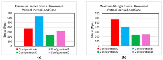
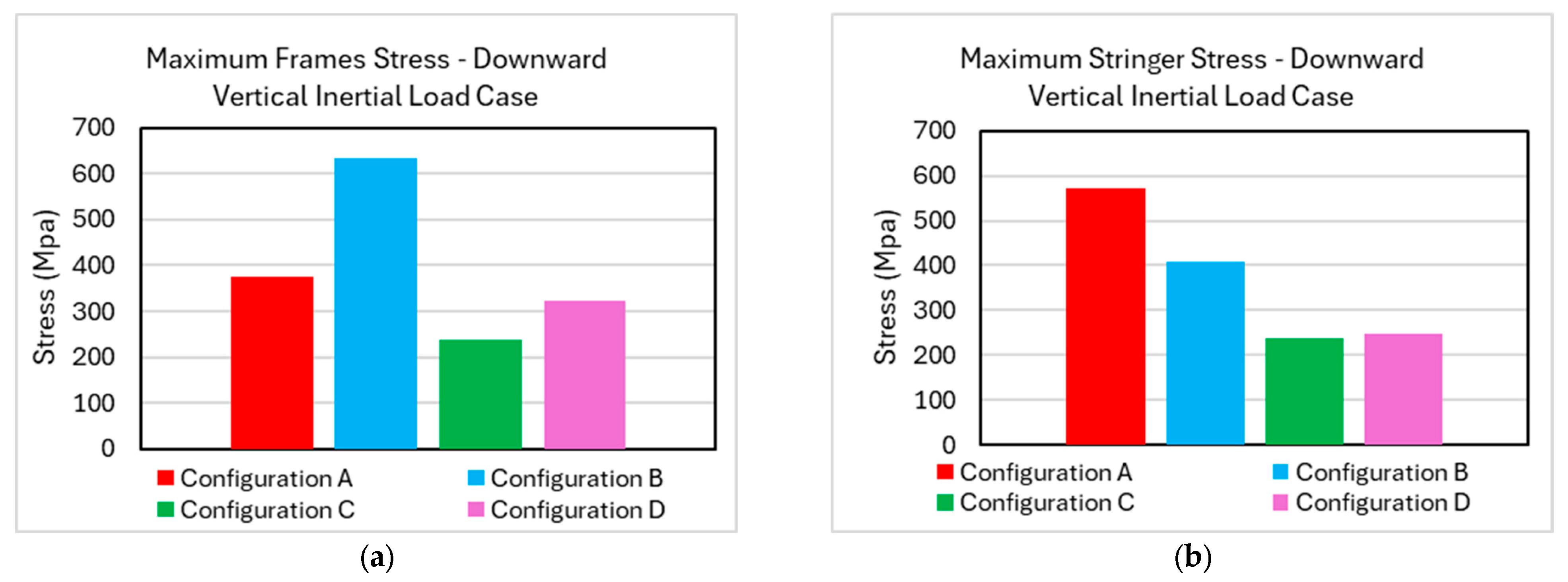
Configuration B exhibits the least favorable fuselage response, with higher stress concentrations observed in frames in Figure 26a, while configuration A exhibits the highest level of stress on the stringers.
Figure 26.
Downward vertical inertial load case—maximum stress on the (a) frames and (b) stringers for the four configurations.
To conclude, the downward inertial load case demonstrates that structural integrators positioned closer to the sides of the tank produce more favorable results. Configuration B resulted in bracket stress levels comparable to Configurations C and D, while configuration A led to higher stress levels both on the tank and structural integrators as well as the airframe.
4.3. 3 g Upward Acceleration as Static Inertial Load
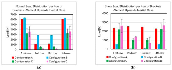
Load distribution trends for the 3 g upward acceleration case are similar to those observed in the downward case. Normal loads, presented in Figure 27a, are higher for configurations A and B compared to Configurations C and D, while transverse loads remain at similar levels for configurations A, C and D. In this scenario, normal loads acting on the brackets are compressive and therefore do not contribute to debonding; nevertheless, accurate representation of both load components remains important for comparative assessment.
Figure 27.
Upward vertical inertial load case, (a) normal load distribution and (b) shear load distribution among the brackets of the four configurations per row of brackets.
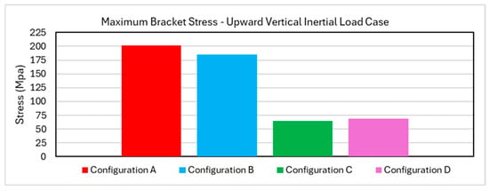
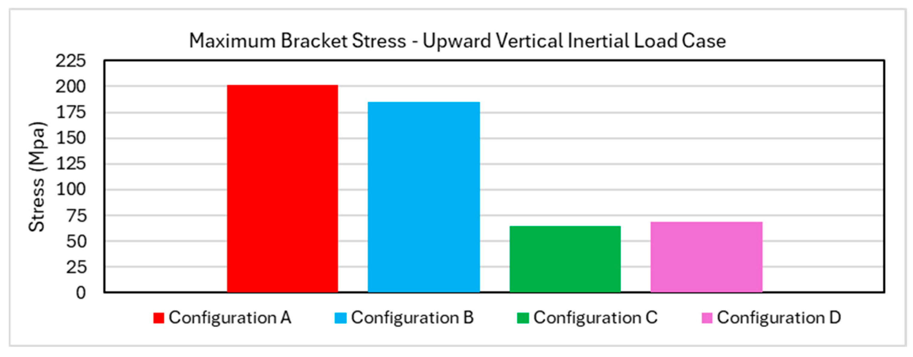
The results in Figure 28 indicate that bracket stress levels across all configurations remain at low levels, and therefore no significant performance differences can be observed. This result is primarily attributed to the lower acceleration requirement in the upward direction.
Figure 28.
Upward vertical inertial load case—peak stress on the brackets.
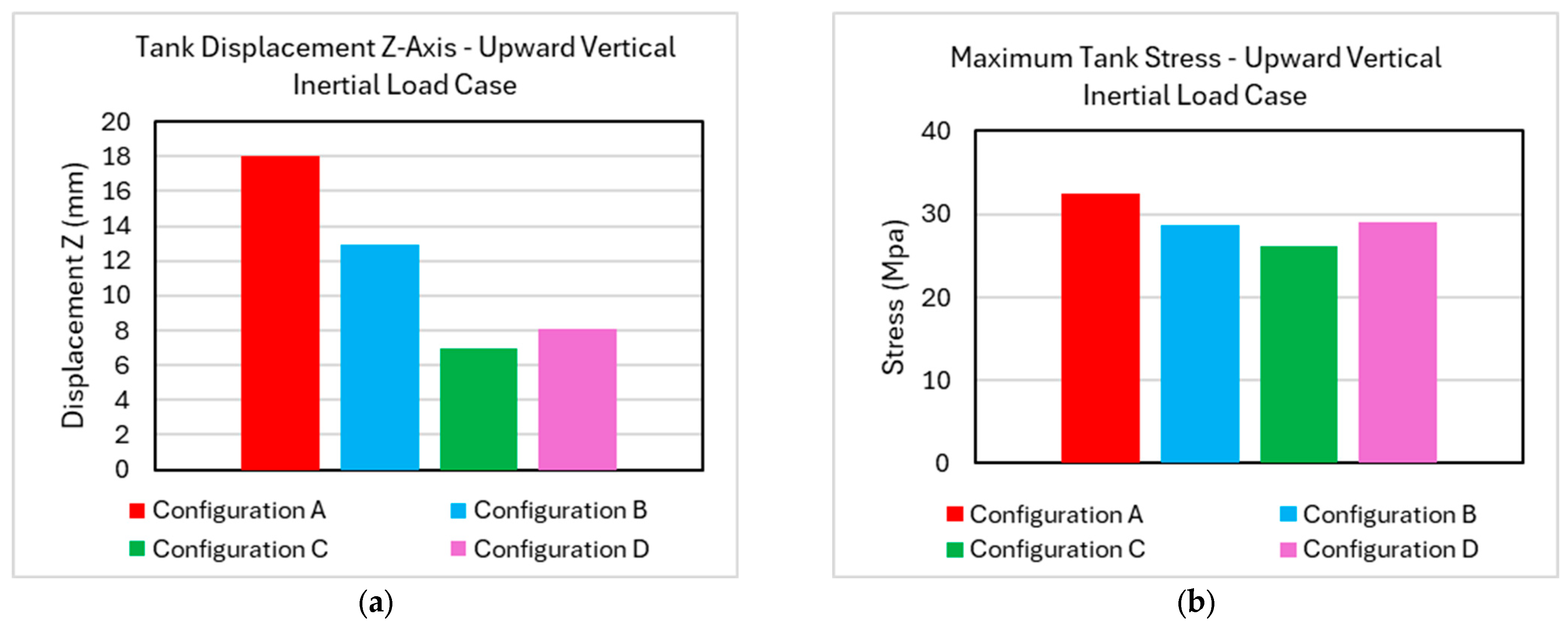
Figure 29a,b indicate that tank displacement and stress levels are similarly low for all configurations, and no configuration-specific limitations are identified.
Figure 29.
Upward vertical inertial load case, (a) maximum tank displacement, (b) maximum stress on the tank.
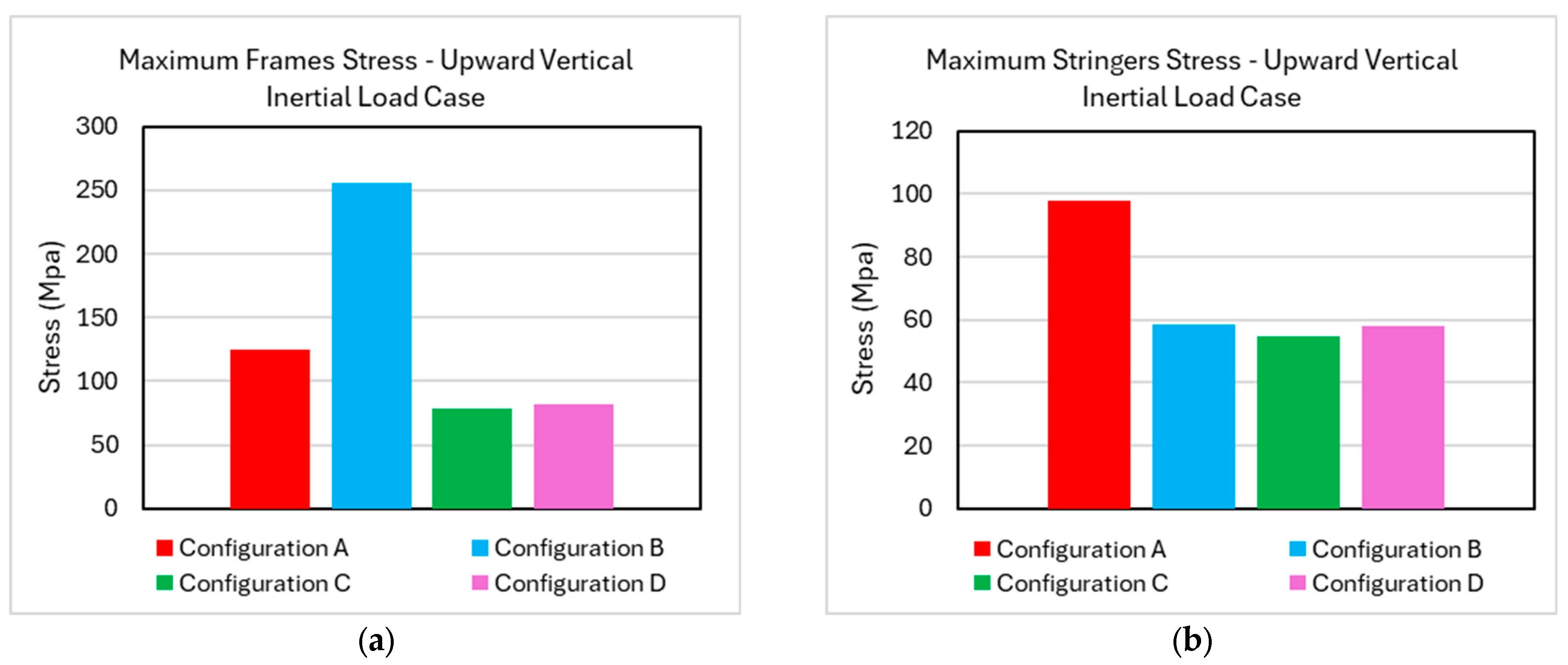
Stress levels in the fuselage frames and stringers also remain low, although configuration B exhibits higher stress concentrations in the frames as illustrated in Figure 30. Overall, all configurations meet the requirements for this inertial load case, provided appropriate sizing and local optimization are applied.
Figure 30.
Upward vertical inertial load case—maximum stress on the (a) frames and (b) stringers for the four configurations.
Regardless, while the results bear resemblance to the downward acceleration inertial load case, stress levels, tank displacement and deformation remained at low levels for all four configurations.
4.4. 3 g Lateral Acceleration as Static Inertial Load
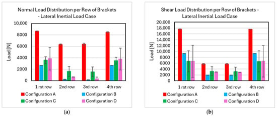
Results for the lateral acceleration case are presented next. Load distributions are examined in terms of both local normal (Z-axis) and transverse (Y-axis) components in Figure 31a and Figure 31b respectively. Configuration A experiences significantly higher transverse loads in addition to normal loads, a direct consequence of the bracket placement relative to the tank center of mass.
Figure 31.
Lateral inertial load case, (a) normal load distribution and (b) shear load distribution among the brackets of the four configurations per row of brackets.
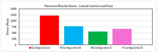
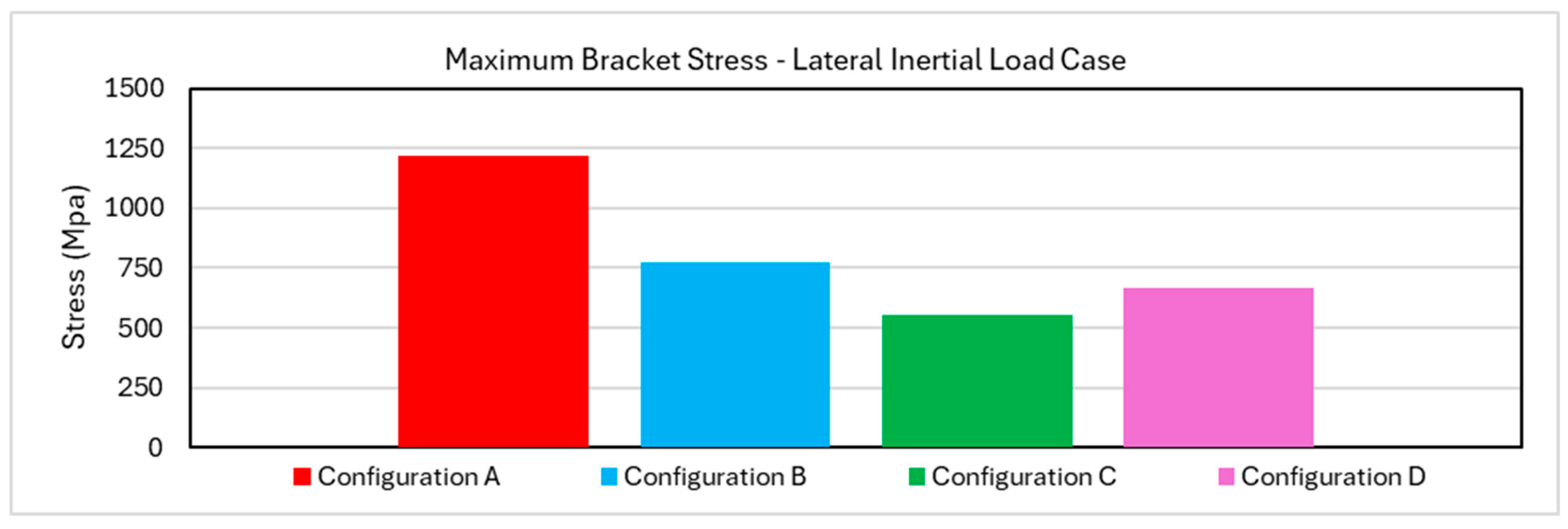
Stress analysis of the brackets confirms that configuration A is poorly suited to resist lateral inertial loads, with substantially higher stress levels compared to the other configurations, as indicated by the high stress levels in Figure 32. Although configuration A demonstrated adequate performance under longitudinal loading, its proximity to the top of the fuselage crown limits its ability to restrain lateral tank motion.
Figure 32.
Lateral inertial load case—peak stress on the brackets.
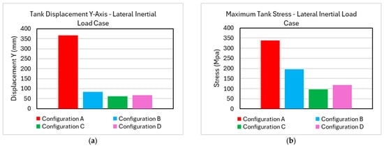
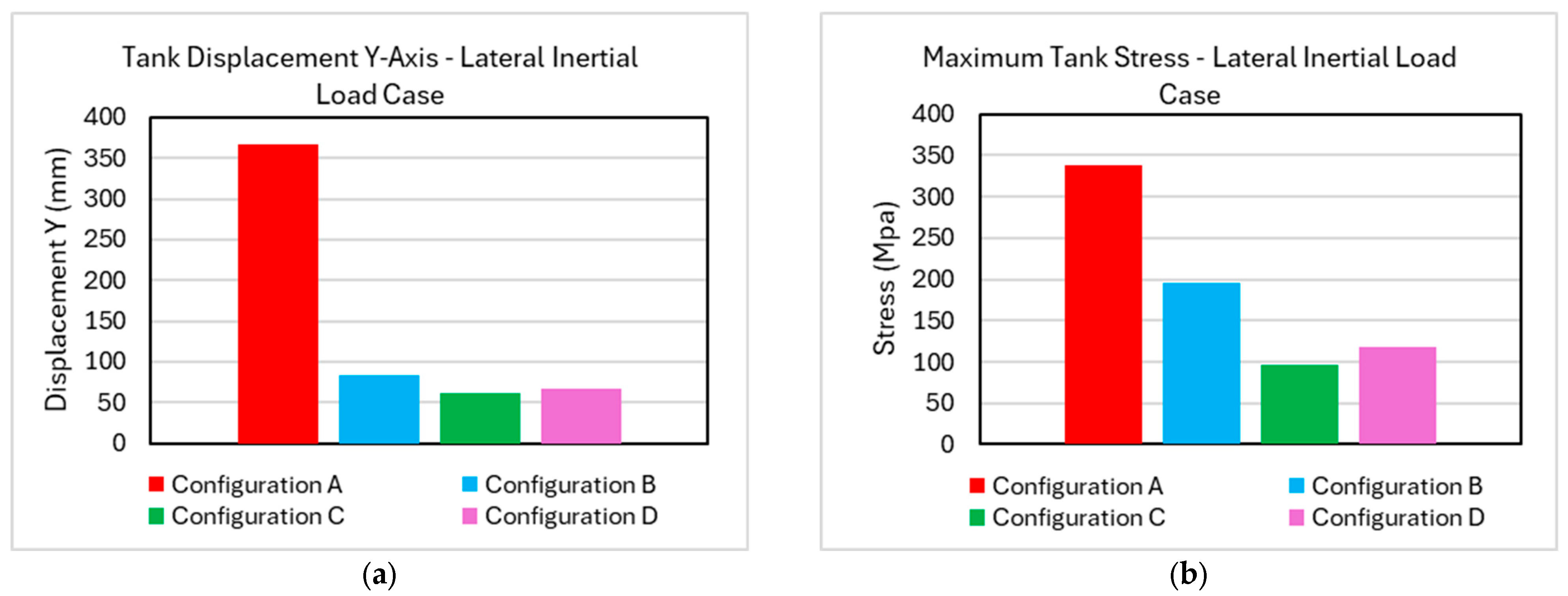
This behavior is further reflected in the tank response, with Configuration A exhibiting higher lateral displacement and stress levels, illustrated in Figure 33a and Figure 33b respectively. The remaining configurations demonstrate similar and acceptable performance.
Figure 33.
Lateral inertial load case, (a) maximum tank displacement, (b) maximum stress on the tank.
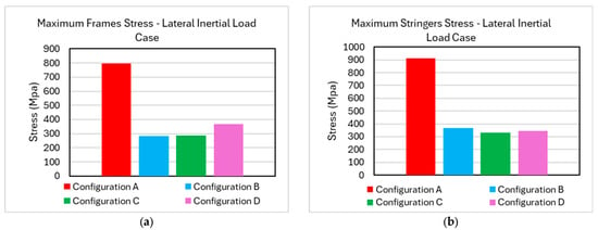
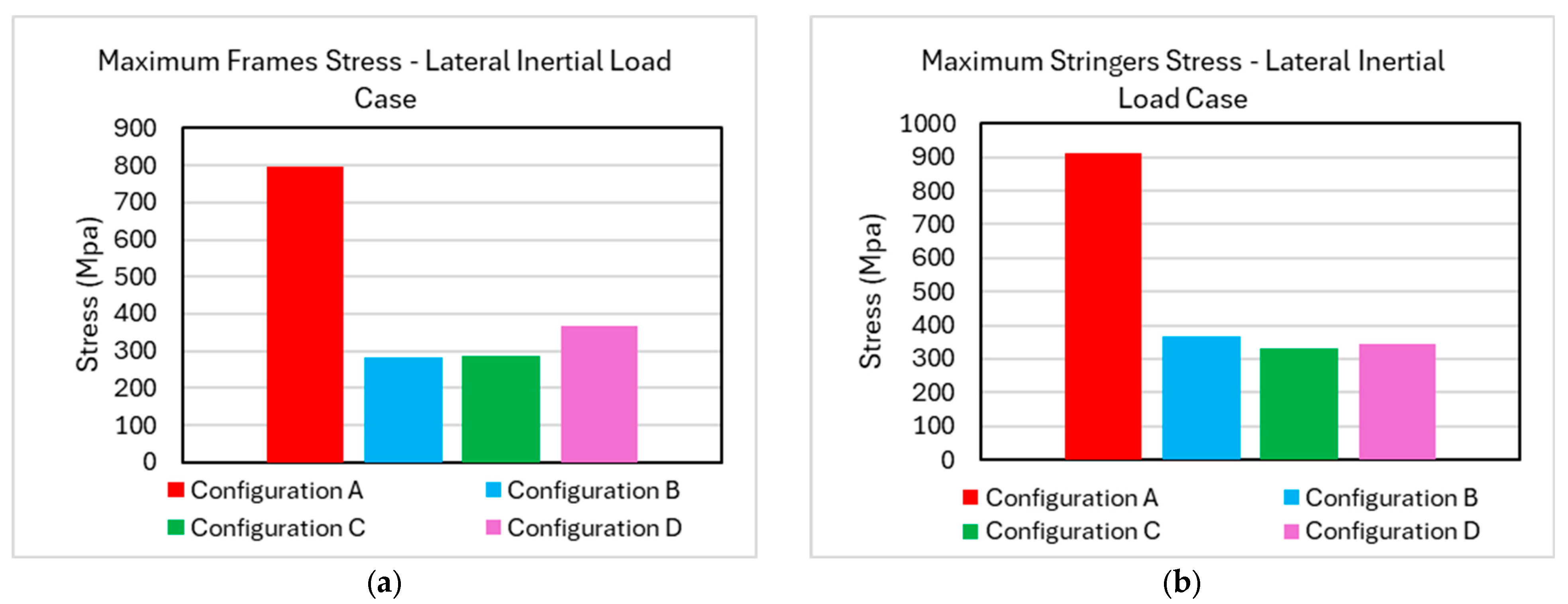
The fuselage response follows the same trend, with configuration A producing more localized and elevated stress levels in both frames and stringers as indicated in Figure 34.
Figure 34.
Lateral inertial load case—maximum stress on the (a) frames and (b) stringers for the four configurations.
Configurations B, C and D displayed similar performance and acceptable stress levels. Configuration A serves as a clear indication of the need to laterally restrain the tank, in the case of mounting from the top of the airframe.
4.5. Disbond Analysis
Following the stress and displacement analysis presented above, local analysis at component-level was performed to assess the potential debonding resistance of the structural integrators. For each configuration and inertial load case, the bracket experiencing the highest tensile and shear loads was selected for detailed modeling of the adhesive interface using the Cohesive Zone Modeling approach, as shown in Figure 35.
Figure 35.
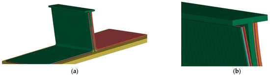
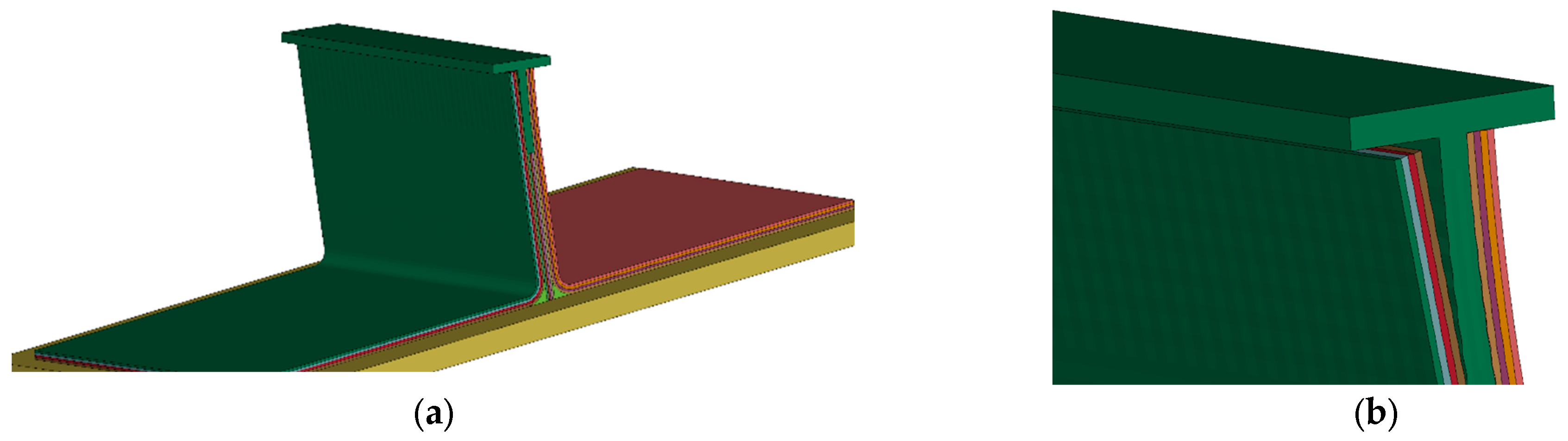
CZM analysis—disbond of bracket from frame, (a) isometric view, (b) close-up of disbond.
The analysis results indicated that the fuselage/tank structural interfaces of all four configurations are capable of sustaining the applied loads for all inertial load cases examined, except the 9 g forward acceleration. In the 9 g scenario, debonding was predicted, driven primarily by the bending of the brackets and fuselage frames. Redirecting these loads to be predominantly axial would significantly reduce the risk of debonding. In Figure 35 the disbond between the bracket and the frame under the loading exerted by the longitudinal inertial load is presented.
A summary of the peak loads extracted from the global analyses and the corresponding loads recorded in the CZM simulations are provided in Table 11.
Table 11.
Comparison between expected load from parametric analysis and maximum load calculated by component-level CZM analysis.
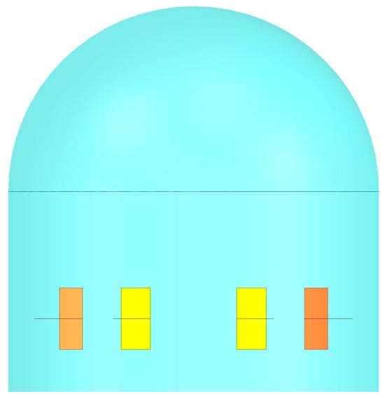
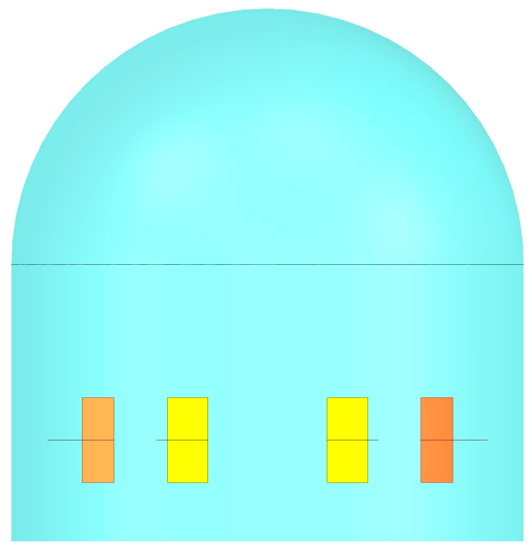
The load displayed in Table 11 is the resultant load while in Figure 14a, Figure 23, Figure 27 and Figure 31 the axial or transverse to the orientation of the bracket component of the force is presented. In Figure 36, the outer and inner brackets of the first row are presented, to illustrate the position of the most critical brackets examined in the component-level analysis.
Figure 36.
Outer brackets highlighted in orange hue and inner brackets highlighted in yellow hue.
The performed analysis identified the main aspects that need to be taken into consideration in the LH2 tank structural integration. Configuration A provided acceptable results only under longitudinal inertial loads. However, the performance under lateral inertial loads was significantly worse than the other configurations and is therefore not considered acceptable. Although configuration B’s performance resulted in stress levels not significantly higher for most load cases than Configurations C and D that possessed more brackets, its performance under longitudinal inertial loads severely lacked in comparison to the other configurations. Configuration C provided the best performance both for the tank as well as the airframe under all loading conditions, while Configuration D provided similar results and therefore constitutes an acceptable optimization of the 16 bracket configuration. Therefore, Configurations C and are D can sufficiently transfer the loads for the tank to the fuselage under all of the load cases. They prevail over the other two configurations, highlighting the need to effectively restrain the tank under all loading directions as well as the minimum acceptable total bond area between brackets and frames to maintain uniform load transfer examined as the one corresponding to Configuration D, equal to 134,272 mm2. Configuration D is considered an optimized version of Configuration C, providing this mass saving, while Configuration C provides further redundancy in case of bracket disbond.
5. Conclusions and Future Work
The present study assessed the feasibility and the performance of several variations in a structural integration concept for liquid hydrogen (LH2) tanks integration within a fuselage barrel section representative of hybrid–electric regional aircraft. Taking into account the crashworthiness perspective, the positioning of the tank towards the upper fuselage crown and its fixation to the upper fuselage section was selected, in order to allow excessive deformation of the lower fuselage structure, without a direct contact with the tank during crash landing events.
The simulation results demonstrated the feasibility of the developed concept, as well as that an effective LH2 tank integration requires structural configurations capable of accommodating inertial loads acting in multiple directions, rather than being optimized for a single dominant load case. More specifically, configurations optimized primarily for longitudinal loading were shown to perform poorly under lateral accelerations, and vice versa, highlighting the need for balanced multi-directional load transfer. Increased bracket count and improved load-path continuity resulted in more uniform load distribution, reduced peak stresses in both the tank and the fuselage and improved overall restraint performance.
Based on the developed numerical model, detailed design and optimization of the integration brackets can be performed, taking into consideration the results of the performed analyses and incorporating energy absorbing structures beneath the tank, as well as within the structural integrators themselves. An integrated solution combining optimized support brackets with strategically placed energy-absorbing structures is expected to result in tank integrity under high-magnitude longitudinal and vertical inertial loads.
Author Contributions
Conceptualization, P.G. and G.L.; methodology, P.G.; software, P.G. and I.S.; validation, I.S.; formal analysis, P.G.; investigation, P.G.; writing—original draft preparation, P.G.; writing—review and editing, P.G. and G.L.; visualization, P.G.; supervision, G.L. All authors have read and agreed to the published version of the manuscript.
Funding
This research was funded by Hybrid Electric Regional Fuselage & Empennages (HERFUSE). This project has received funding from the Clean Aviation Joint Undertaking under the European Union’s Horizon Europe research and innovation program under grant agreement ID 101140567 (https://doi.org/10.3030/101140567).
Data Availability Statement
Results are not available, raw data are cited in text.
Conflicts of Interest
The authors declare no conflicts of interest.
References
- Hybrid-Electric Regional Fuselage & Empennages|HERFUSE|Project|Fact Sheet|HORIZON, CORDIS|European Commission. Available online: https://cordis.europa.eu/project/id/101140567 (accessed on 12 January 2026).
- Liquid Hydrogen Fuelled Aircraft—System Analysis (CRYOPLANE)|CRYOPLANE|Project|Fact Sheet|FP5, CORDIS|European Commission. Available online: https://cordis.europa.eu/project/id/G4RD-CT-2000-00192 (accessed on 12 January 2026).
- Hydrogen Lightweight & Innovative Tank for zero-Emission Aircraft|H2ELIOS|Project|Fact Sheet|HORIZON, CORDIS|European Commission. Available online: https://cordis.europa.eu/project/id/101102003 (accessed on 12 January 2026).
- Flight Demonstration of a Liquid Hydrogen Load-Bearing Tank in an Unmanned Cargo Platform|flhying Tank|Project|Fact Sheet|HORIZON, CORDIS|European Commission. Available online: https://cordis.europa.eu/project/id/101101946 (accessed on 12 January 2026).
- Banerjee, T.; Balasubramanian, G. Hydrogen diffusion induced dislocation transformations in a nickel superalloy. Fuel 2025, 384, 134064. [Google Scholar] [CrossRef] [Scilit]
- Grenoble, R.; Gates, T. Hydrogen Permeability of Polymer Matrix Composites at Cryogenic Temperatures. In 46th AIAA/ASME/ASCE/AHS/ASC Structures, Structural Dynamics and Materials Conference; American Institute of Aeronautics and Astronautics: Reston, VA, USA, 2012. [Google Scholar] [CrossRef] [Scilit]
- Rompokos, P.; Kissoon, S.; Roumeliotis, I.; Nalianda, D.; Nikolaidis, T.; Rolt, A. Liquefied Natural Gas for Civil Aviation. Energies 2020, 13, 5925. [Google Scholar] [CrossRef] [Scilit]
- Mukhopadhaya, J.; Rutherford, D. Performance Analysis of Evolutionary Hydrogen-Powered Aircraft; International Council on Clean Transportation: Washington, DC, USA, 2022. [Google Scholar]
- Mangold, J.; Silberhorn, D.; Moebs, N.; Dzikus, N.; Hoelzen, J.; Zill, T.; Strohmayer, A. Refueling of LH2 Aircraft—Assessment of Turnaround Procedures and Aircraft Design Implication. Energies 2022, 15, 2475. [Google Scholar] [CrossRef] [Scilit]
- Nisi, T.; Tang, Z. A review of hydrogen-powered distributed propulsion aircraft. Clean Energy 2025, 9, 148–176. [Google Scholar] [CrossRef] [Scilit]
- Tiwari, S.; Pekris, M.J.; Doherty, J.J. A review of liquid hydrogen aircraft and propulsion technologies. Int. J. Hydrogen Energy 2024, 57, 1174–1196. [Google Scholar] [CrossRef] [Scilit]
- El-Adawy, M.; Hamdy, M.; Khedr, A.M.; Ismael, M.A.; Elserfy, K.; Moral, A.; Nemitallah, M.A. Hydrogen-Powered Aviation: Status and Perspectives. Energy Fuels 2025, 39, 11469–11503. [Google Scholar] [CrossRef] [Scilit]
- Johnson, W.L.; Baltman, E.; Koci, F.D. Assessment of insulation systems for aircraft liquid hydrogen tanks. IOP Conf. Ser. Mater. Sci. Eng. 2024, 1301, 012062. [Google Scholar] [CrossRef] [Scilit]
- Tzoumakis, G.; Fotopoulos, K.; Lampeas, G. Multi-Physics Digital Model of an Aluminum 2219 Liquid Hydrogen Aircraft Tank. Aerospace 2024, 11, 161. [Google Scholar] [CrossRef] [Scilit]
- Xisto, C.; Lundbladh, A. Design and Performance of Liquid Hydrogen Fuelled Aircraft for Year 2050 EIS. In Proceedings of the 33rd Congress of the International Council of the Aeronautical Sciences, Stockholm, Sweden, 4–9 September 2022. [Google Scholar]
- Giannopoulos, I.K.; Theotokoglou, E.E. Liquid Hydrogen Storage Tank Loading Generation for Civil Aircraft Damage Tolerance Analysis. J. Phys. Conf. Ser. 2024, 2692, 012048. [Google Scholar] [CrossRef] [Scilit]
- Spencer, R. Certification considerations for the configuration of a hydrogen-fuelled aeroplane. Aeronaut. J. 2023, 127, 213–231. [Google Scholar] [CrossRef] [Scilit]
- Gomez, A.; Smith, H. Liquid hydrogen fuel tanks for commercial aviation: Structural sizing and stress analysis. Aerosp. Sci. Technol. 2019, 95, 105438. [Google Scholar] [CrossRef] [Scilit]
- Onorato, G.; Proesmans, P.; Hoogreef, M.F.M. Assessment of hydrogen transport aircraft. CEAS Aeronaut. J. 2022, 13, 813–845. [Google Scholar] [CrossRef] [Scilit]
- Gallois, A.; Giannopoulos, I.K.; Theotokoglou, E.E. Liquid Hydrogen Storage Tank Virtual Crashworthiness Design Exploration for Civil Aircraft. J. Phys. Conf. Ser. 2024, 2692, 012049. [Google Scholar] [CrossRef] [Scilit]
- Modular Joints for Aircraft Composite Structures|MOJO|Project|Fact Sheet|FP6, CORDIS|European Commission. Available online: https://cordis.europa.eu/project/id/30871 (accessed on 12 January 2026).
- Reifsnider, K.L. (Ed.) Progress in Durability Analysis of Composite Systems: Proceedings of the Third International Conference on Progress in Durability Analysis of Composite Systems, Blacksburg, Virginia, USA, 14–17 September 1997; Balkema: Rotterdam, The Netherlands, 1998. [Google Scholar]
- Wang, C.M.; Shin, C.S. Residual properties of notched [0/90]4S AS4/PEEK composite laminates after fatigue and re-consolidation. Compos. Part B Eng. 2002, 33, 67–76. [Google Scholar] [CrossRef] [Scilit]
- Shafaq, S.; Donough, M.J.; Bhandari, B.; Phillips, A.W.; St John, N.A.; Prusty, B.G. Experimental study on the influence of optimised automated fibre placement processing parameters on the impact response and residual flexural strength of AS4/APC-2 laminates. Compos. Sci. Technol. 2025, 259, 110945. [Google Scholar] [CrossRef] [Scilit]
- Ding, S.; Tong, J.W.; Shen, M.; Huo, Y.Z. Rate-dependence Analysis of Interlaminar Stresses of Thick Thermoplastic Composite AS4-PEEK Laminate. J. Thermoplast. Compos. Mater. 2007, 20, 111–131. [Google Scholar] [CrossRef] [Scilit]
- Kawai, M.; Masuko, Y.; Kawase, Y.; Negishi, R. Micromechanical analysis of the off-axis rate-dependent inelastic behavior of unidirectional AS4/PEEK at high temperature. Int. J. Mech. Sci. 2001, 43, 2069–2090. [Google Scholar] [CrossRef] [Scilit]
- Zou, H.; Yin, W.; Cai, C.; Wang, B.; Liu, A.; Yang, Z.; Li, Y.; He, X. The Out-of-Plane Compression Behavior of Cross-Ply AS4/PEEK Thermoplastic Composite Laminates at High Strain Rates. Materials 2018, 11, 2312. [Google Scholar] [CrossRef] [Scilit]
- Rae, P.J.; Brown, E.N.; Orler, E.B. The mechanical properties of poly(ether-ether-ketone) (PEEK) with emphasis on the large compressive strain response. Polymer 2007, 48, 598–615. [Google Scholar] [CrossRef] [Scilit]
- Tserpes, K.I.; Labeas, G.N. Mesomechanical analysis of non-crimp fabric composite structural parts. Compos. Struct. 2009, 87, 358–369. [Google Scholar] [CrossRef] [Scilit]
- Llopart P., L.; Tserpes, K.I.; Labeas, G.N. Experimental and numerical investigation of the influence of imperfect bonding on the strength of NCF double-lap shear joints. Compos. Struct. 2010, 92, 1673–1682. [Google Scholar] [CrossRef] [Scilit]
- On the Mechanical Performance of Noncrimp Fabric H-Shaped Adhesively Bonded Joints—K.I. Tserpes, Jacques Cinquin, Sp. Pantelakis. 2011. Available online: https://journals.sagepub.com/doi/10.1177/0021998310385590 (accessed on 14 July 2025).
- Tserpes, K.I.; Ruzek, R.; Mezihorak, R.; Labeas, G.N.; Pantelakis, S.G. The structural integrity of a novel composite adhesively bonded flap-track beam. Compos. Struct. 2011, 93, 2049–2059. [Google Scholar] [CrossRef] [Scilit]
- Gillespie, J.W.; Carlsson, L.A.; Pipes, R.B.; Rothschilds, R.; Trethewey, B.; Smiley, A. Delamination Growth in Composite Materials, NAS 1.26:178066, Feb. 1986. Available online: https://ntrs.nasa.gov/citations/19860012147 (accessed on 16 July 2025).
- Tserpes, K.I.; Pantelakis, S.; Kappatos, V. The effect of imperfect bonding on the pull-out behavior of non-crimp fabric Pi-shaped joints. Comput. Mater. Sci. 2011, 50, 1372–1380. [Google Scholar] [CrossRef] [Scilit]
- Jokinen, J.; Wallin, M.; Kanerva, M. The influence of the number of adhesive plies (FM 300-2) on fracture properties. In Proceedings of the 32nd Congress of the International Council of the Aeronautical Sciences, Shanghai, China, 6–10 September 2021. [Google Scholar]
- Ishai, O.; Rosenthal, H.; Sela, N.; Drukker, E. Effect of selective adhesive interleaving on interlaminar fracture toughness of graphite/epoxy composite laminates. Composites 1988, 19, 49–54. [Google Scholar] [CrossRef] [Scilit]
- Scarborough, H.L. The Investigation of Toughness and Its Role in Fatigue Performance of Adhesively Bonded Joints. Master’s Thesis, Washington State University, Washington, DC, USA, 2015. [Google Scholar]
- Charon, A. Hot/Wet Environmental Degradation of Honeycomb Sandwich Structure Representative of F/A-18: Discolouration of Cytec FM-300 Adhesive; Aeronautical and Maritime Research Laboratory (DSTO): Fishermans Bend, Australia, 2000. [Google Scholar]
- LaPlante, G.; Lee-Sullivan, P. Moisture Effects on FM300 Structural Film Adhesive: Stress Relaxation, Fracture Toughness, and Dynamic Mechanical Analysis. J. Appl. Polym. Sci. 2005, 95, 1285–1294. [Google Scholar] [CrossRef] [Scilit]
- CS-25 Amendment 28|EASA. Available online: https://www.easa.europa.eu/en/document-library/certification-specifications/cs-25-amendment-28 (accessed on 28 December 2025).
- SHELL181. Available online: https://www.mm.bme.hu/~gyebro/files/ans_help_v182/ans_elem/Hlp_E_SHELL181.html (accessed on 28 December 2025).
- LS-DYNA Manual R 8.0—Vol I, Welcome to the LS-DYNA Support Site. Available online: https://lsdyna.ansys.com/wp-content/uploads/2025/02/LS-DYNA_Manual_Volume_I_R8.0.pdf (accessed on 7 January 2026).
- LS-DYNA Manual R 8.0—Vol II, Welcome to the LS-DYNA Support Site. Available online: https://ftp.lstc.com/anonymous/outgoing/jday/manuals/LS-DYNA_Manual_Volume_II_R8.0.pdf (accessed on 7 January 2026).

Disclaimer/Publisher’s Note: The statements, opinions and data contained in all publications are solely those of the individual author(s) and contributor(s) and not of MDPI and/or the editor(s). MDPI and/or the editor(s) disclaim responsibility for any injury to people or property resulting from any ideas, methods, instructions or products referred to in the content. |
© 2026 by the authors. Licensee MDPI, Basel, Switzerland. This article is an open access article distributed under the terms and conditions of the Creative Commons Attribution (CC BY) license.