


Abstract
This paper presents a modular Power Conditioning and Distribution Unit (PCDU) designed for small satellites. The proposed system features a highly adaptable architecture capable of managing a total power throughput of up to 100 W, with specific limits defined by mission-dependent thermal and redundancy configurations. Aligned with the New Space paradigm, the implementation relies on Commercial Off-The-Shelf (COTS) components, a strategy that drastically reduces development and manufacturing costs without compromising reliability. The system has been optimized for operation in harsh environments, including high vacuum, ionizing radiation, and extreme thermal gradients. The design incorporates strict redundancy and fault-tolerance criteria to provide a robust solution for critical subsystems. Comprehensive validation was performed through functional testing, Total Ionizing Dose (TID) radiation campaigns, and Thermal Vacuum (TVAC) cycles. Experimental results demonstrate that the PCDU withstands high-vacuum thermal cycling and cumulative radiation doses exceeding 75 kRad. These findings confirm that the developed unit is a cost-effective, high-reliability solution suitable for both Low Earth Orbit (LEO) and deep-space missions.
Keywords:
COTS; fault tolerance; modular architecture; new space; PCDU; power electronics; small satellites; TID; TVAC 1. Introduction
In recent decades, the aerospace sector has experienced exponential growth in the deployment of small satellites, particularly under the CubeSat standard [1]. This phenomenon is the result of technological advances that have made it possible to match the capabilities of these platforms with those of traditional satellites, but with a disruptive reduction in development costs. This democratization of space has enabled a spectrum of missions ranging from simple deployments in Low Earth Orbit (LEO) [2] to highly complex deep-space missions [3,4,5], characterized by extreme thermal gradients and high levels of ionizing radiation.
In this context, the New Space philosophy emerged, prioritizing cost optimization through the use of Commercial Off-The-Shelf (COTS) components. These components offer an ecosystem of functionalities and integration levels far superior to traditionally used components, known as “Rad-Hard” (Radiation Hardened), allowing for higher integration levels and greater power density at a fraction of the cost compared to the traditional approach. However, the main drawback is the lack of guarantees regarding their behaviour in hostile environments [6]. Space is one of the harshest known environments, where temperatures fluctuate across wide ranges and high radiation doses damage electronic devices. This vulnerability is especially critical in the Power Conditioning and Distribution Unit (PCDU), the subsystem responsible for energy management and the primary vector for catastrophic failures in space missions [7], whose mass is about 30% of the total dry mass of the satellite [8].
While this may not pose a major problem for short-duration LEO missions, it becomes critical when medium- or long-duration missions are intended, both in LEO and deep space. Although the use of COTS components is viable for short-term LEO missions, it becomes an unacceptable risk factor for medium- or long-term missions unless specific design strategies, such as single-point failure tolerance are applied [9,10]. In this regard, many commercial off-the-shelf PCDUs [11,12] offer highly integrated solutions for standard LEO applications but often lack the modular flexibility to scale power requirements or the inherent system-level redundancy needed for high radiation or high-reliability missions without significant custom redesign. Furthermore, while there are specialized PCDUs specifically designed for deep-space scientific missions [3,13,14], these are often custom-made, non-modular, and entail high development costs and lead times.
To address these limitations, this work presents a novel, highly modular, and fault-tolerant PCDU architecture specifically developed to operate in high-radiation environments. The primary innovation lies in its ‘building-block’ design, which allows for a scalable configuration and implements system-level redundancy through independent modules. Unlike existing commercial solutions that prioritize extreme miniaturization at the expense of redundancy, the proposed design integrates robust analog control loops and extensive protections to achieve a reliability figure comparable to traditional large-scale satellites but maintaining the cost-effectiveness and form factor of the CubeSat standard.
The presented PCDU manages solar-generated power of up to 100 W, integrating up to four Maximum Power Point Trackers (MPPTs) [15,16,17] to optimize solar generation. The energy storage system is compatible with 8.2 V and 16.4 V battery configurations (~40 Wh). Power distribution is carried out through redundant and protected buses, which can be regulated or unregulated. The PCDU features hybrid management that combines hardware control with telemetry and telecommand (TM/TC) via integrated microcontrollers.
The robustness of the design has been validated through an extensive testing plan that includes functional tests, Total Ionizing Dose (TID) radiation campaigns at the National Center of Accelerators (CNA) of Spain, and Thermal Vacuum (TVAC) tests at ALTER’s facilities. The results confirm the unit’s capability to operate under high-vacuum conditions, within a temperature range of −20 °C to +60 °C and withstanding a cumulative dose of up to 75 kRad, consolidating it as a versatile solution for the sector.
2. PCDU Design
As previously introduced, the PCDU is based on a fully modular architecture integrating up to two independent battery buses. Its configuration is highly scalable, allowing the system to be adapted by adding or removing modules according to specific mission requirements. The design of this architecture has been driven by a comprehensive Failure Mode, Effects, and Criticality Analysis (FMECA) at the component level. Based on this analysis, different mitigation strategies were adopted according to the criticality of each subsystem. For highly critical functions, such as battery overvoltage protection, a triple-modular redundancy with a majority-voted strategy is implemented. In contrast, for Solar Array Regulators (SARs), Power Distribution Unit (PDU), and Isolated DC/DC Converter (DCX) modules, where a single component failure might disable a specific regulator or distribution channel, the design focuses on robust protection circuitry to ensure that internal faults remain isolated and cannot propagate to the rest of the system or the primary power buses. This ensures that the system can be configured to be fully redundant depending on the selection and arrangement of the modules, allowing for the implementation of system-level redundancy for critical functions without compromising the modularity of the platform.
The different modules are integrated into a vertical stack featuring lateral connectors at the top for interconnection with the remaining subsystems via two backplanes. These backplanes carry both communication lines (telemetry and telecommand) and the primary power distribution buses. Notably, each module integrates a dedicated microcontroller, facilitating independent communication with the On-Board Computer (OBC) for data and status management.
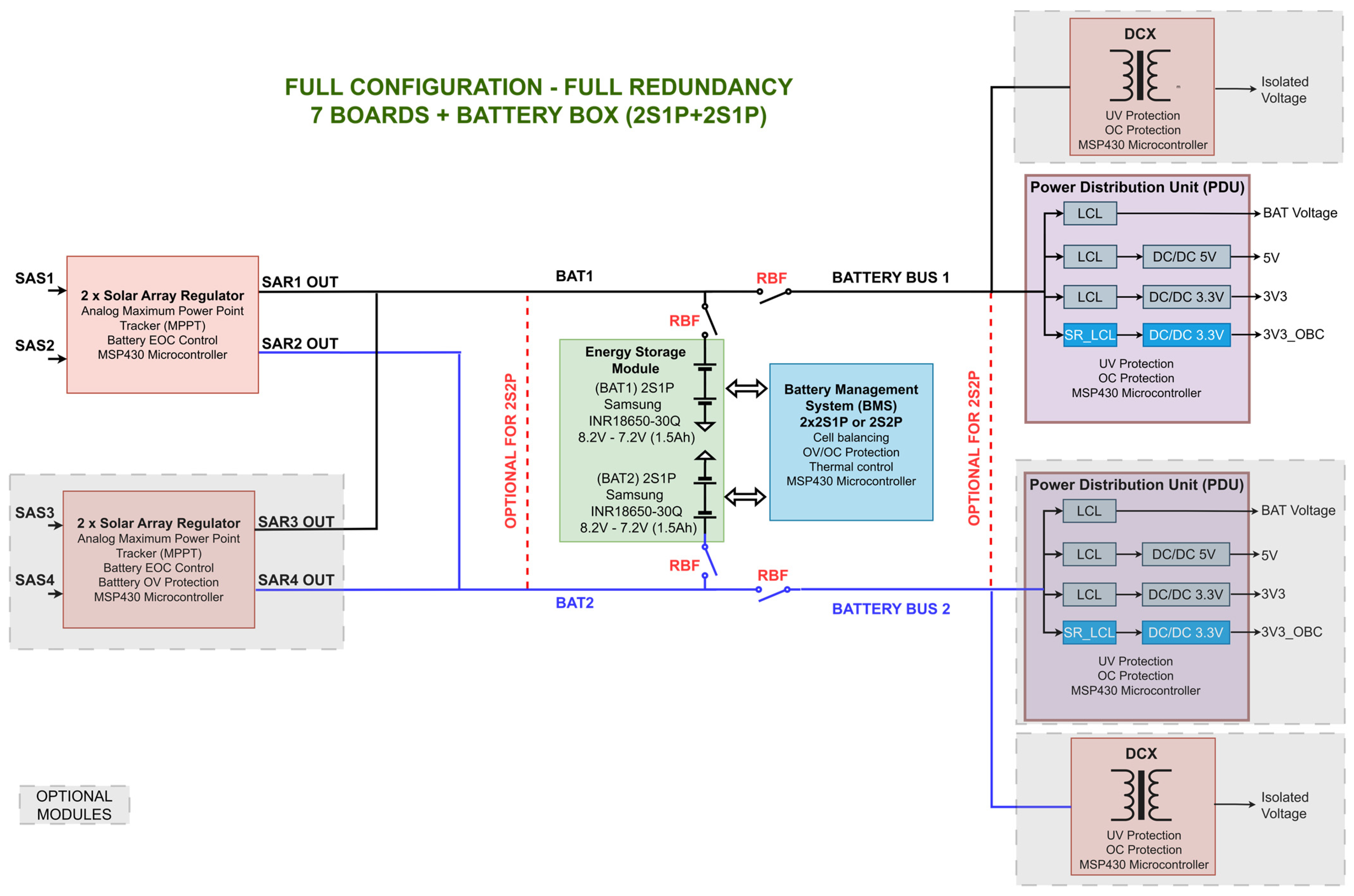
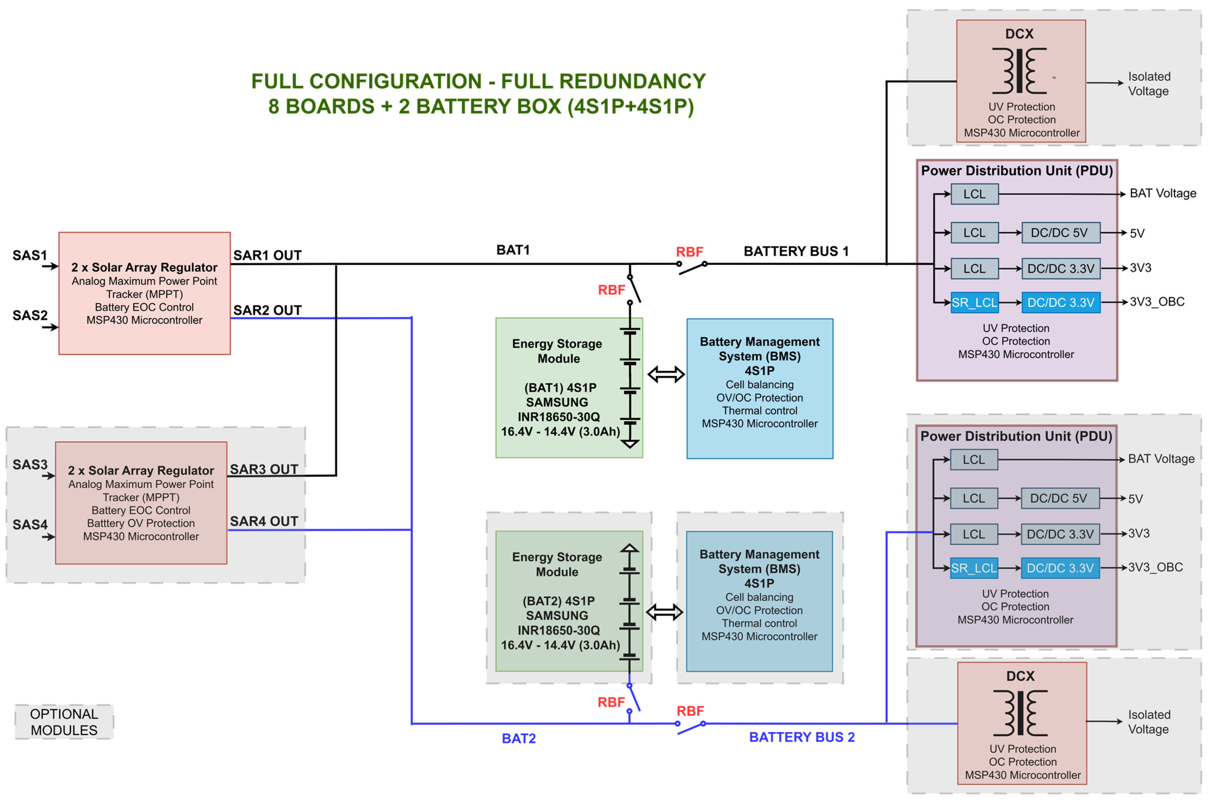
Figure 1 and Figure 2 illustrates two possible configurations for a redundant PCDU with 8.2 V and 16.4 V batteries, respectively. Optional modules are shaded, as their integration depends on the required redundancy level and energy demands. The current module catalog includes:
Figure 1.
Diagram of the proposed PCDU in a 8.2 V battery configuration.
Figure 2.
Diagram of the proposed PCDU in a 16.4 V battery configuration.
- •
- Solar Array Regulator (SAR) Module.
- •
- Energy Storage Module.
- •
- Battery Management System (BMS) Module.
- •
- Power Distribution Unit (PDU) Module.
- •
- Isolated Converter Module (DCX).
The buck converters across these modules are based on the LT3845 controller. This current-mode controller is adjustable up to 500 kHz and allows input and output voltage regulation using the control pin [16]. This component has been selected because it has a space-grade equivalent, the RH3845MK, which has already been proposed for space missions by NASA [18] and has been explored in other rad-tol applications [19]. Furthermore, custom external control loops have been implemented using operational amplifiers previously validated [20], ensuring stable operation even under cumulative dose degradation [21]. By injecting the external control signal into a high-impedance node, the design aims to isolate the regulation from potential internal failures of the bypassed amplifier stage. This approach ensures that the design architecture remains compatible with high-reliability requirements while leveraging COTS benefits during development. However, for a final flight mission, these COTS devices would undergo a rigorous screening and lot-acceptance testing process. This pre-processing is essential to ensure that the specific components used in the flight hardware share identical characteristics and performance under space conditions, maintaining the design’s compatibility if COTS version is not utilized.
The main characteristics of each unit are described below:
2.1. Solar Array Regulator Module
The Solar Array Regulator module manages energy extraction from the solar panels. Each module features two fully independent phases, comprising a buck-type regulator, an analog MPPT system [22], and auxiliary electronics. Utilizing a dual-loop control, each regulator can operate in either MPPT mode—extracting maximum energy when batteries are not fully charged—or EOC (End of Charge) mode, regulating the battery end of charge, similar to the approach shown in [20]. The modules are designed to withstand solar panel open-circuit voltages up to 50 V and output currents up to 2.2 A per section (SAS). In terms of power capacity, each of the two independent phases is capable of managing up to 25 W, resulting in a maximum total input power of 50 W per SAR module. As shown in Figure 1 and Figure 2, a single PCDU can integrate one or two SAR modules. Through an interconnection matrix, the output of each converter can be routed to a specific battery (BAT1 or BAT2). Connecting multiple outputs to the same battery provides system-level redundancy.
2.2. Energy Storage Module
This module is responsible for storing generated energy to power subsystems during eclipse periods or peak demand. The module houses four 18650 Li-ion cells, a widely recognized standard in the sector [23]. These four cells can be configured as a 2S2P battery, two 2S1P batteries (see Figure 1), or a 4S1P battery (see Figure 2). Based on the evaluation performed in [24], the INR18650-30Q cell was selected, featuring a 3000 mAh capacity. This results in a total stored energy of 42.5 Wh and a maximum discharge current of 15 A per parallel string. The module includes a redundant heater system to ensure operation within the manufacturer’s safety thermal range.
2.3. Battery Management System Module
The Battery Management System (BMS) ensures balance between cells to optimize lifespan and mitigate degradation. It also manages redundant heater control. This is the only module with two variants depending on the battery configuration:
- •
- BMS Module for 2S Batteries: Integrates an active equalizer known as a Delta-Structured Switched Capacitor Equalizer, detailed in [25]. Each module includes two balancing units, capable of managing one 2S2P battery or two 2S1P batteries.
- •
- BMS Module for 4S Batteries: Employs a passive balancing system that dissipates excess energy when the cell voltage exceeds a threshold of 4.1 V.
2.4. DCX Converter Module
This module implements a high-efficiency isolated DCX converter with Zero Voltage Zero Current (ZVZC) switching, based on the topology shown in [27]. It features fixed gain (step-up or step-down) and is powered directly from one of the battery buses (BATTERY BUS 1 or 2) through filtering and protection stages. Each unit manages an output power of 30 W and is intended for loads requiring galvanic isolation. Its integration is optional, allowing for up to two modules depending on mission demand.
2.5. Power Distribution Unit Module
The Power Distribution Unit extracts energy from the battery bus and distributes it to the satellite subsystems. It features four main outputs (see Figure 1 and Figure 2): three protected by Class 3 Latching Current Limiters (LCLs) [28] controlled by the OBC, and a fourth critical output dedicated exclusively to powering the OBC. The latter includes a “Class 1” Retriggerable LCL (RLCL) and Under Voltage Lockout (UVLO) protection, ensuring the OBC is the first system to recover power after a critical battery discharge. Regarding distribution, the unregulated bus can supply up to 25W, while the regulated buses include 5 V and 3.3 V converters, delivering up to 15 W and 10 W, respectively. Excluding the dedicated OBC bus, each PDU module is capable of distributing up to 50 W to the satellite loads. Each PCDU can integrate one or two PDUs; OBC power redundancy is achieved by combining the outputs of two PDU modules through the use of “ideal diodes”.
3. Prototype Implementation
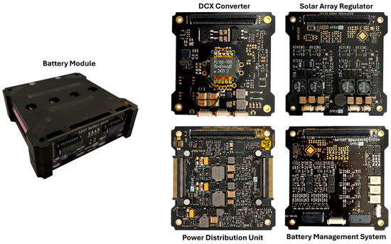
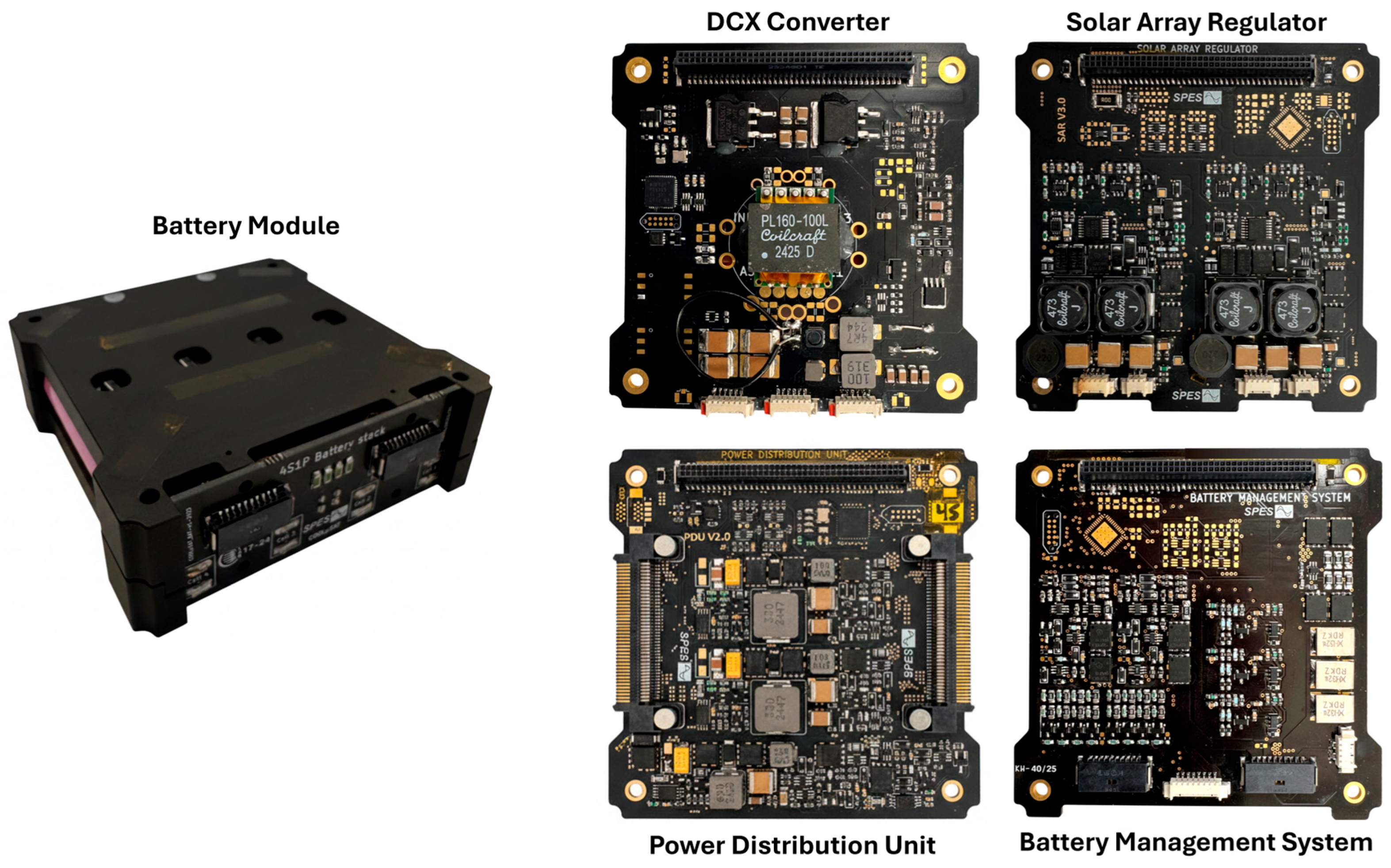
In this work, two PCDU variants have been implemented, tailored to distinct operational scenarios by combining the previously described modules. Figure 3 illustrates the physical implementation of each developed module.
Figure 3.
Implemented modules of each subsystem.
The configuration of both units is detailed below:
3.1. PCDU for Deep-Space Missions (8.2 V)
This first configuration is designed for a 6U CubeSat scientific mission to the asteroid Apophis. Given that the asteroid is located at a heliocentric distance of 0.92 Astronomical Unit (AU), an irradiance of approximately 1500 W/m2 is expected during illumination periods (71% of the orbit period), with a thermal range between −50 °C and +35 °C. It should be noted that these parameters are employed as a preliminary baseline to establish a challenging deep-space environment for the PCDU. As this is a conceptual study rather than a finalized flight mission, the exhaustive analysis required for a real-world mission—including precise orbital dynamics, complex rotation effects, and specific environmental constraints—has not been performed. Instead, this scenario serves to validate the modular architecture’s performance and radiation hardness under conditions significantly more demanding than standard Earth orbits. In this potential scenario, mass, volume, and redundancy are critical factors due to high launch costs and the hostile environment, characterized by high expected radiation doses.
For this mission, the 8.2 V PCDU manages four solar arrays integrated into the two largest surfaces of the satellite. These arrays feature an 8S1P configuration of CESI CTJ30 cells. Table 1 summarizes the modular configuration and design parameters.
Table 1.
8.2 V PCDU Specifications.
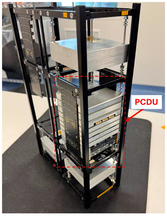
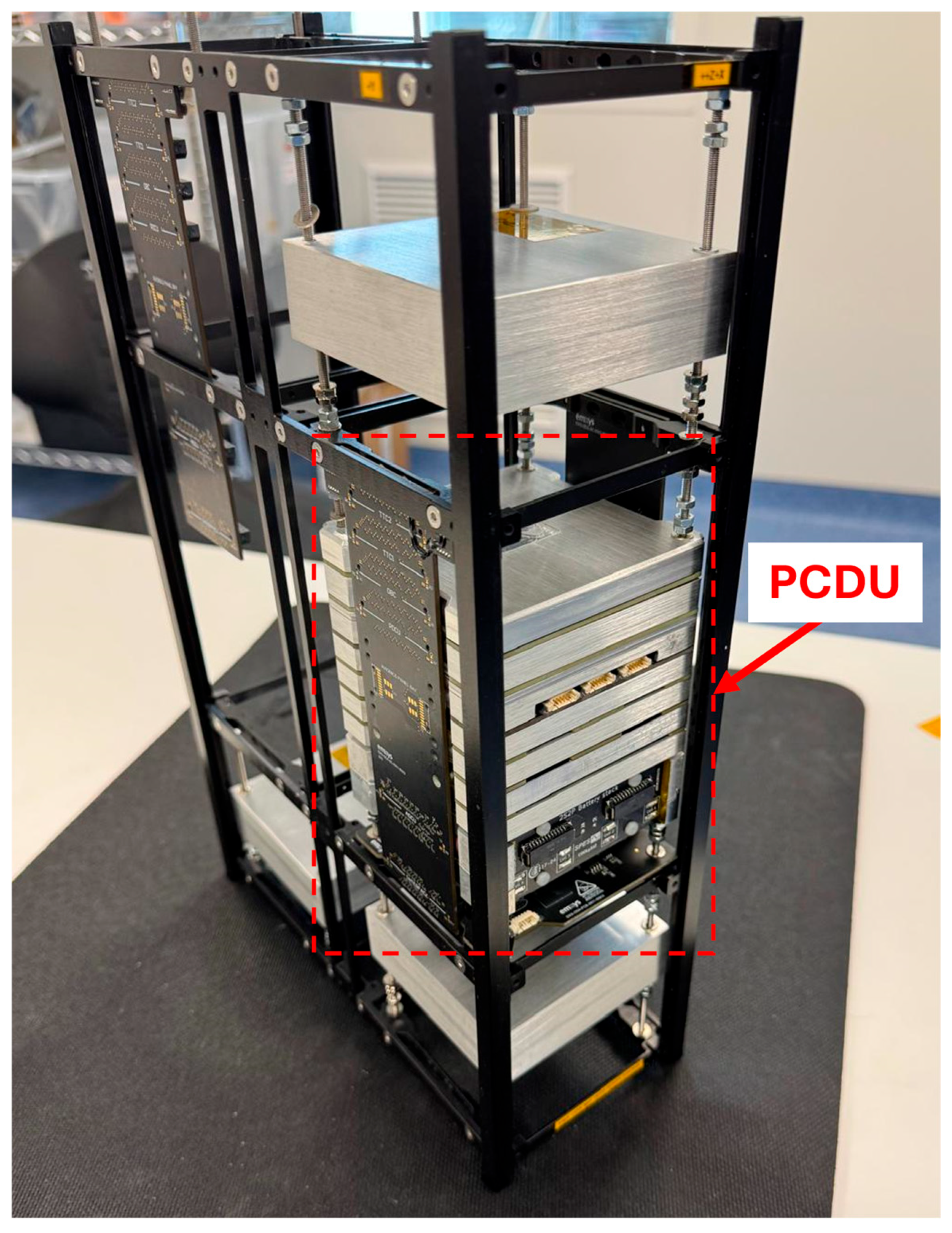
The system is fully redundant and Single Point Failure Free (SPFF), ensuring mission continuity despite the failure of any PCDU module or solar array. In the specific implementation presented here, system redundancy has been prioritized over total managed power. Consequently, for the purpose of quantifying the managed energy in this configuration, only one SAR module and one PDU module are accounted for as active units, while their counterparts operate as redundant backups. Under this configuration, the system manages up to 21.3 W (10.65 W per phase) of input power from the solar arrays and up to 45 W of output power to the loads, as detailed in Table 1. This ensures that the resulting system remains fully redundant and operational even in the event of a module-level failure. The implemented PCDU prototype integrated into a 6U CubeSat platform is shown in Figure 4.
Figure 4.
An 8.2 V PCDU for deep space integrated into a 6U CubeSat structure from EMXYS (Elche, Spain).
The unit has been integrated into a compact block of 87 × 87 × 98 mm with a total mass of 0.9 kg. Of this, 0.18 kg corresponds to the batteries and 0.38 kg to the 2 mm thick aluminium enclosure. Therefore, the mass of the electronics, PCBs, and connectors is approximately 0.34 kg. Regarding the aluminium enclosure, its thickness is presented here as a baseline configuration that must be precisely calculated and adjusted to specific mission requirements based on the expected total ionizing dose. Such shielding calculations, which correlate aluminium thickness with radiation attenuation, are well-documented in the literature [29] and fall outside the primary scope of this architectural study. Consequently, the reported mass of the electronics remains the core constant, while the final mechanical enclosure will serve as a mission-dependent variable.
3.2. PCDU for LEO Missions (16.4 V)
This variant has been designed for a satellite platform weighing between 50 and 100 kg that operates in Low Earth Orbit (LEO, ~600 km). The mission focuses on massive data acquisition and on-board processing via artificial intelligence (AI) for a minimum period of 3 years. In this orbit (1 AU), the irradiance is approximately 1320 W/m2 with an illumination period of roughly 70%. For this platform, a propulsion system based on water electrolysis is proposed [30].
Due to the high energy demands of AI data processing and the water electrolysis propulsion system—which requires the DCX module for power conditioning—the satellite is equipped with four solar arrays mounted on two steerable surfaces. Each array employs an 11S2P configuration of CESI CTJ30 cells. Technical specifications are summarized in Table 2.
Table 2.
16.4 V PCDU Specifications.
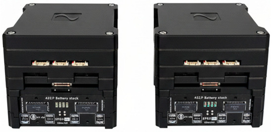
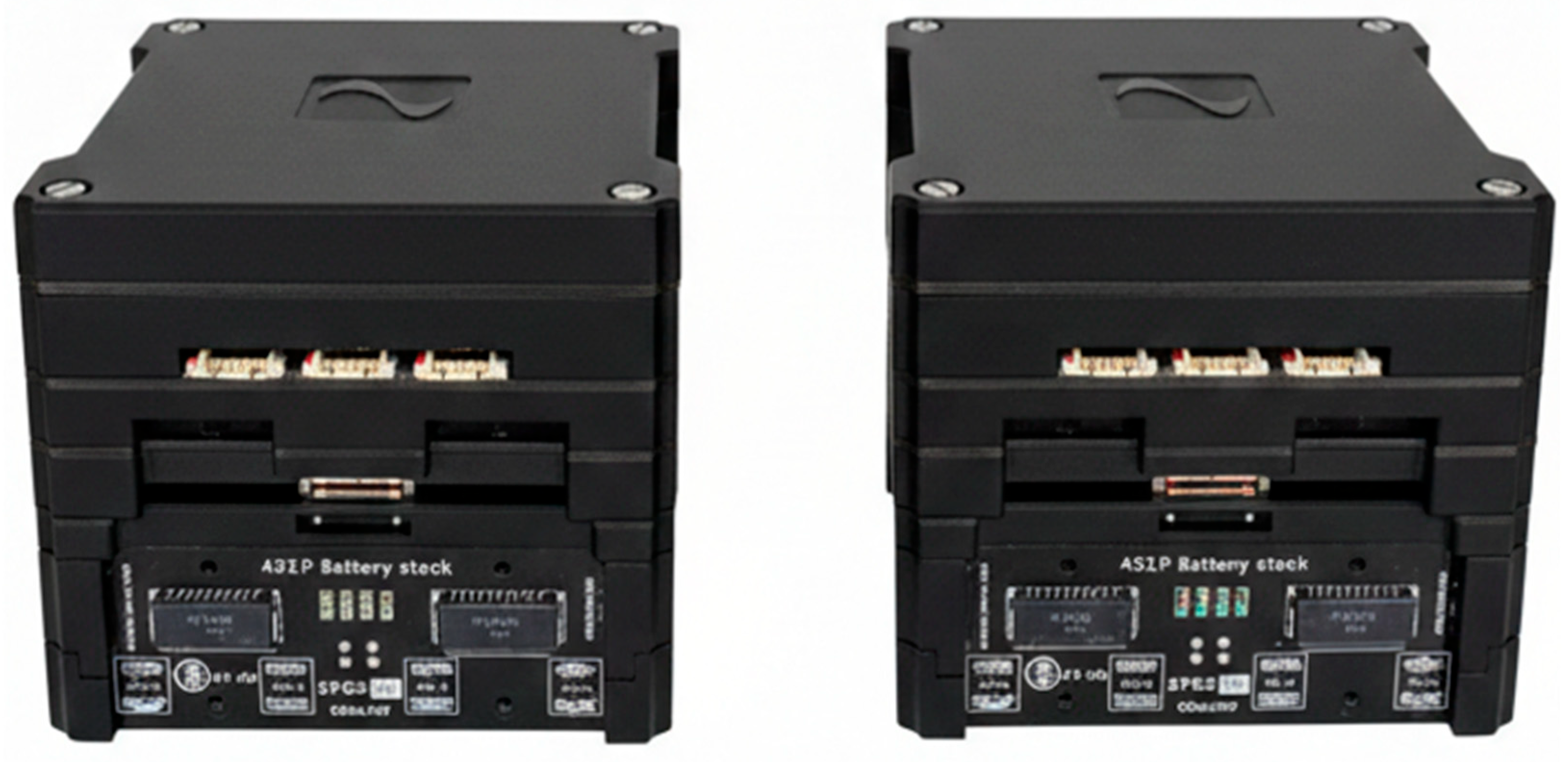
In this design, redundancy is addressed through a distributed architecture by dividing the PCDU into two identical and independent blocks (see Figure 5), which are interconnected via two backplanes. Each block constitutes a complete power chain, integrating its own battery module, BMS, solar array regulator, DCX converter, and power distribution unit. This configuration not only doubles the generation and storage capacity but also eliminates any single point of failure. In the event of an anomaly or failure in one block, the remaining unit can assume critical loads and maintain satellite operability, although the available power would be proportionally reduced.
Figure 5.
Implementation of the 16.4 V PCDU for LEO.
To calculate the maximum system power, all modules are assumed to be operational. For solar energy intake, two SAR modules are considered, each connected to two solar panels with an MPP (Maximum Power Point) of 24.92 W (see Table 2), resulting in a maximum input power of 99.68 W. Regarding the load distribution, the configuration includes two PDU modules (50 W each) and two DCX modules (30 W each), yielding a combined theoretical peak output of 160 W. This figure represents the maximum capacity of the electronic architecture, which does not account for additional system-level or thermal constraints. Consequently, throughout this work, a maximum operational power of 100 W is consistently considered as the rated limit for the system. This 100 W threshold has been experimentally validated through TVAC tests, where the PCDU exhibited stable and correct performance under sustained load. Nevertheless, it is important to note that this figure represents a conservative baseline; the definitive operational power rating must be established through a detailed thermal study of both the PCDU and the rest of the satellite structure, accounting for the specific constraints and environment of the mission profile.
Each block is housed in a 2-mm-thick aluminum enclosure with dimensions of 87 × 87 × 78 mm and a total mass of 0.79 kg. It is worth noting that the battery mass is 0.18 kg, while the mass associated with the electronics, PCBs, and connectors is 0.25 kg. The remaining mass corresponds to the metallic enclosure, the thickness of which can be increased, reduced, or even eliminated depending on the specific radiation mission profile.
4. Experimental Results
To validate the developed modules, several testing campaigns were conducted, classified into laboratory functional tests, TID radiation tests, and TVAC cycling. In these campaigns, the experimental focus has been placed on verifying the system’s functional integrity and fault tolerance under critical conditions, prioritizing these factors over the optimization of energy conversion efficiency.
While the system maintains competitive performance levels for the CubeSat standard, the core objective of these tests is to demonstrate the PCDU’s ability to maintain stable power distribution and subsystem integrity in harsh environments. Therefore, the most significant results regarding dynamic response and survival capabilities are presented below:
4.1. Functional Tests
Some representative tests were selected to evaluate the performance of the various modules under laboratory conditions:
4.1.1. Solar Array Regulator—MPPT
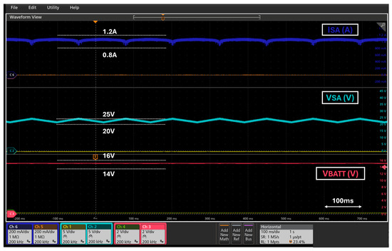
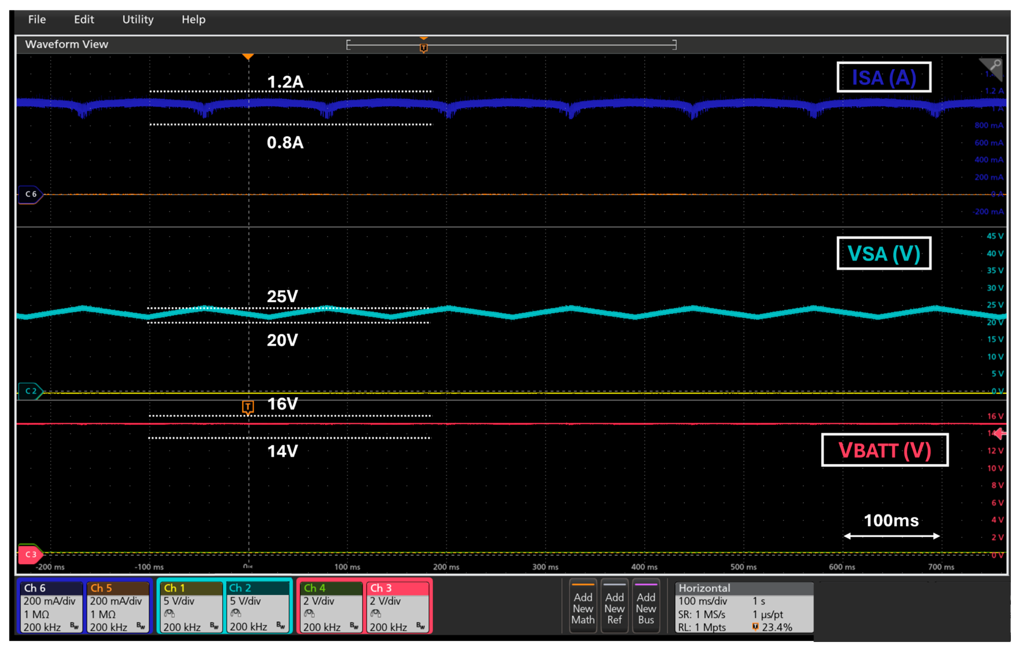
The first test demonstrates the operation of one of the SARs (see Figure 6). The test was performed using the 16.4 V PCDU connected to an ITECH IT-N2133 solar array simulator, configured to replicate the 11S2P solar panel behaviour described in Section 3 (VMPPT = 22.3 V). The oscillogram shows that while the battery is not fully charged, the solar array operating point oscillates around the MPP to maximize power extraction.
Figure 6.
MPPT operation of one of the SARs.
4.1.2. Solar Array Regulator—Transition from MPPT to VEOC
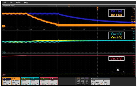
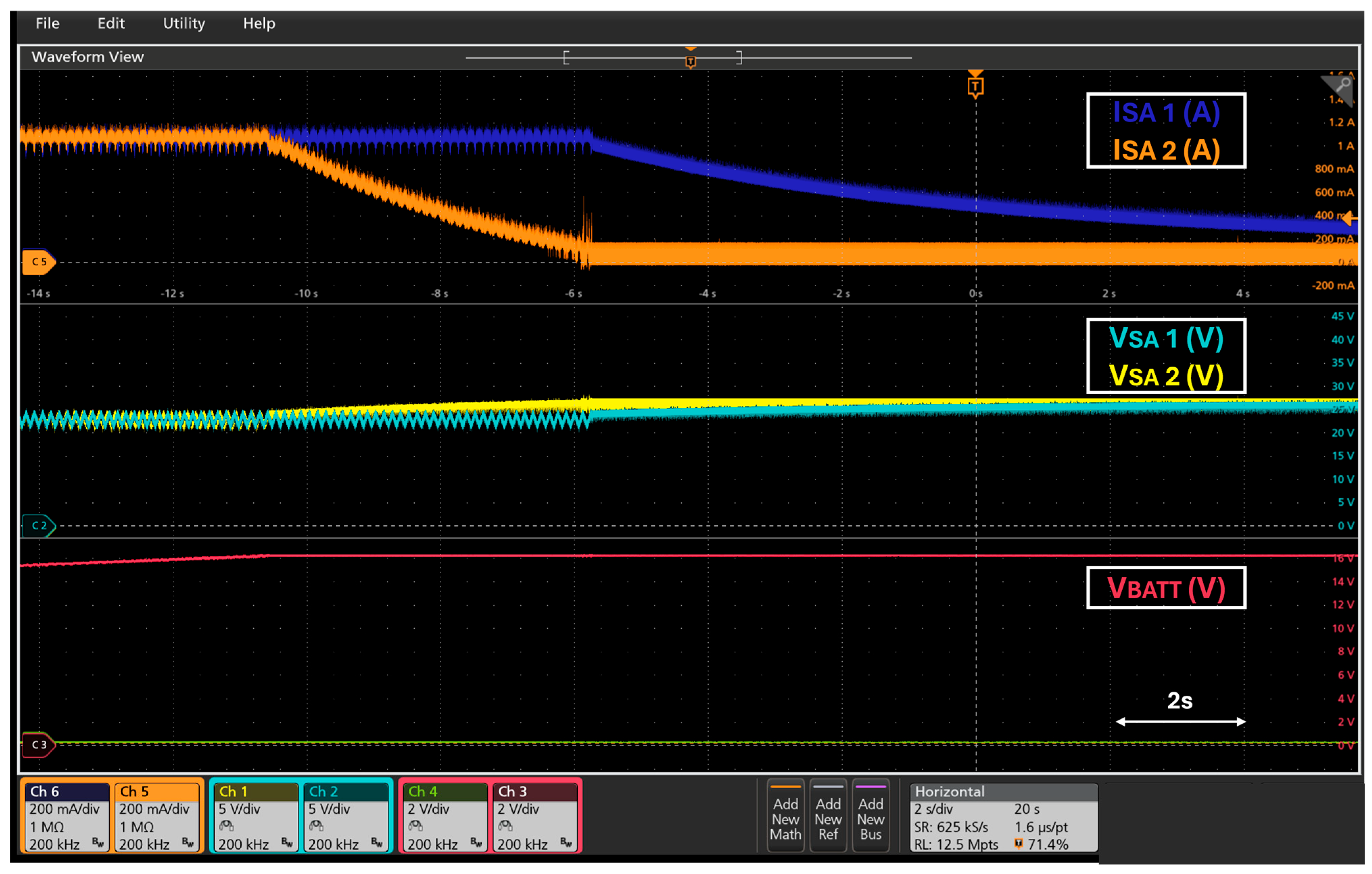
This test illustrates the transition of both converters within a SAR module from MPPT mode to VEOC (End of Charge) mode under the same conditions as the previous test. The oscillogram (see Figure 7) shows that the regulators initially set the solar array operating point around the MPP. As the battery reaches its end-of-charge voltage VEOC, the operating point moves away from the MPP, and the regulators switch to VEOC mode to regulate the battery end-of-charge voltage.
Figure 7.
Transition from MPPT to EOC in both phases of a SAR module.
4.1.3. DCX Converter—Load Transients
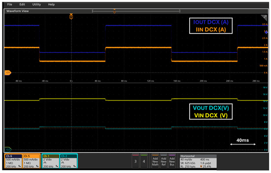
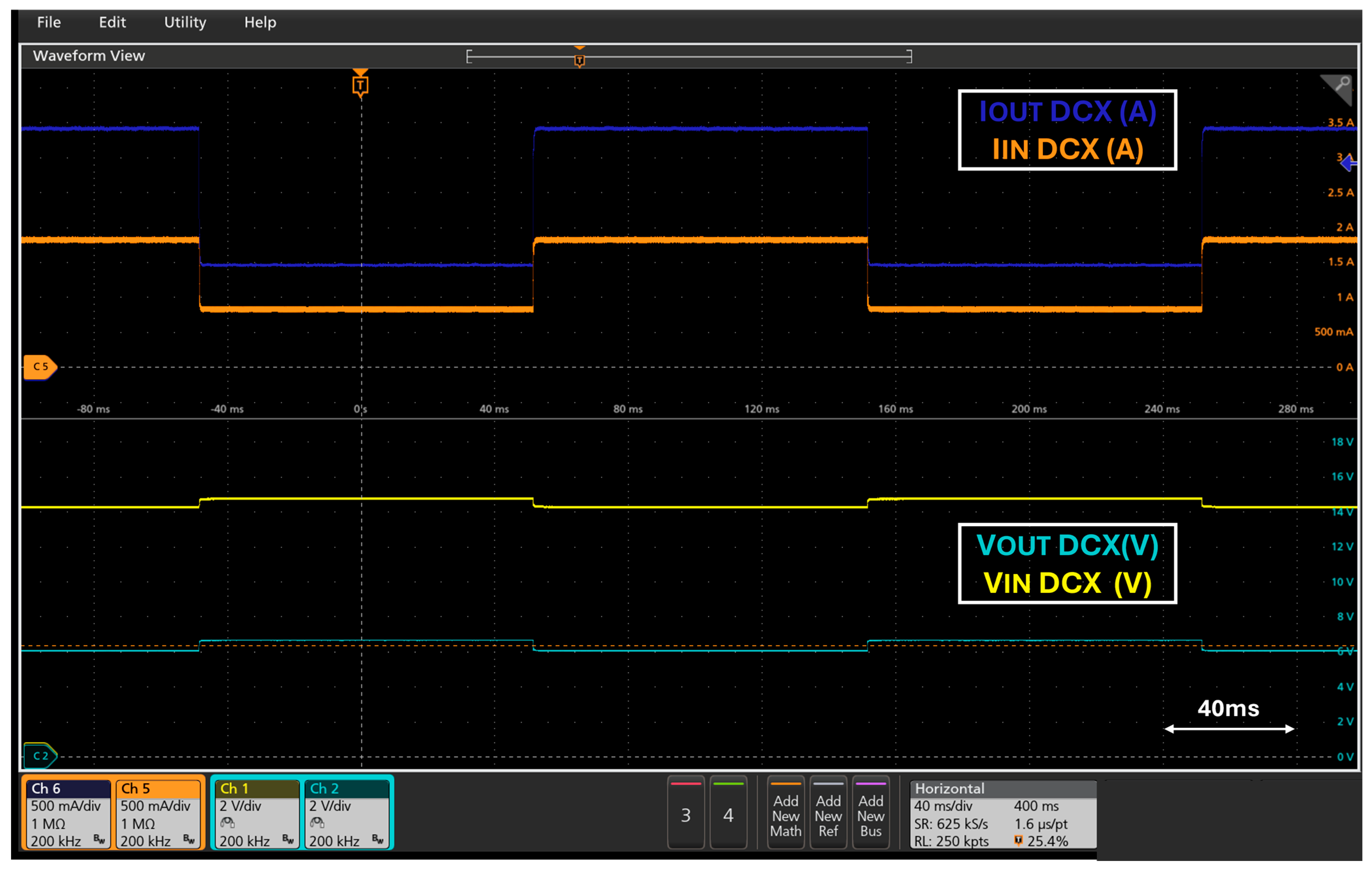
The behaviour of the DCX converter facing load steps was evaluated using the 16.4 V PCDU. A RIGOL DL3021A electronic load was connected to the DCX output, which is powered by the PCDU battery. The electronic load is configured for current steps from 1.5 A to 3.5 A (5 Hz, 50% duty cycle). Figure 8 demonstrates that the converter maintains a stable output voltage (equivalent to half the input voltage) without overshooting or instability. The input and output current signals are also shown.
Figure 8.
DCX converter response to load steps.
4.1.4. 5 V Regulated Bus—Dynamic Response
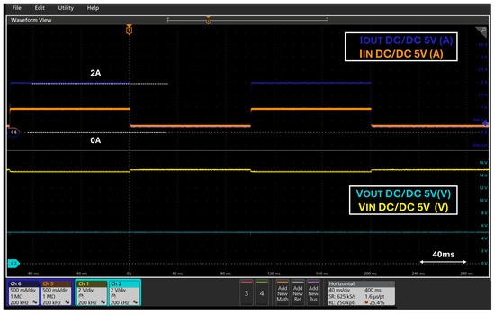
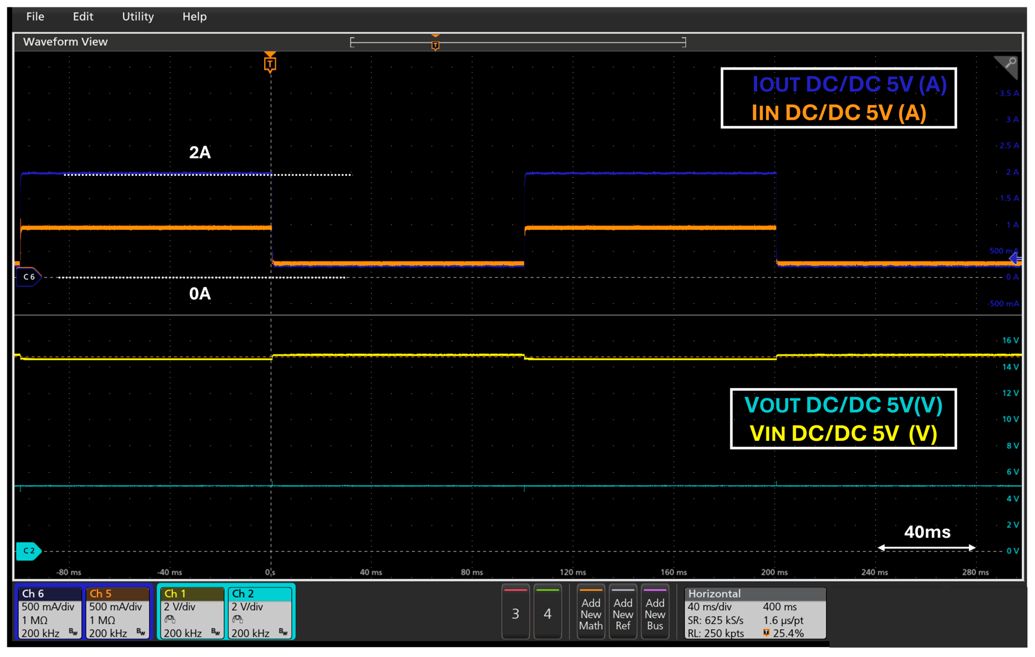
The behaviour of the 5 V regulator integrated into the PDU was analyzed. A RIGOL DL3021A electronic load was connected to the output, performing load steps between 0.2 A and 2 A (5 Hz, 50% duty cycle). The results (see Figure 9) confirm stable regulation at 4.96 V and show the corresponding input and output current signals, validating the control loop’s robustness against abrupt changes in subsystem energy demand.
Figure 9.
Response of the 5 V DC/DC regulator integrated into the PDU.
4.1.5. Unregulated Bus—LCL
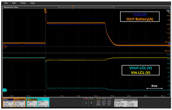
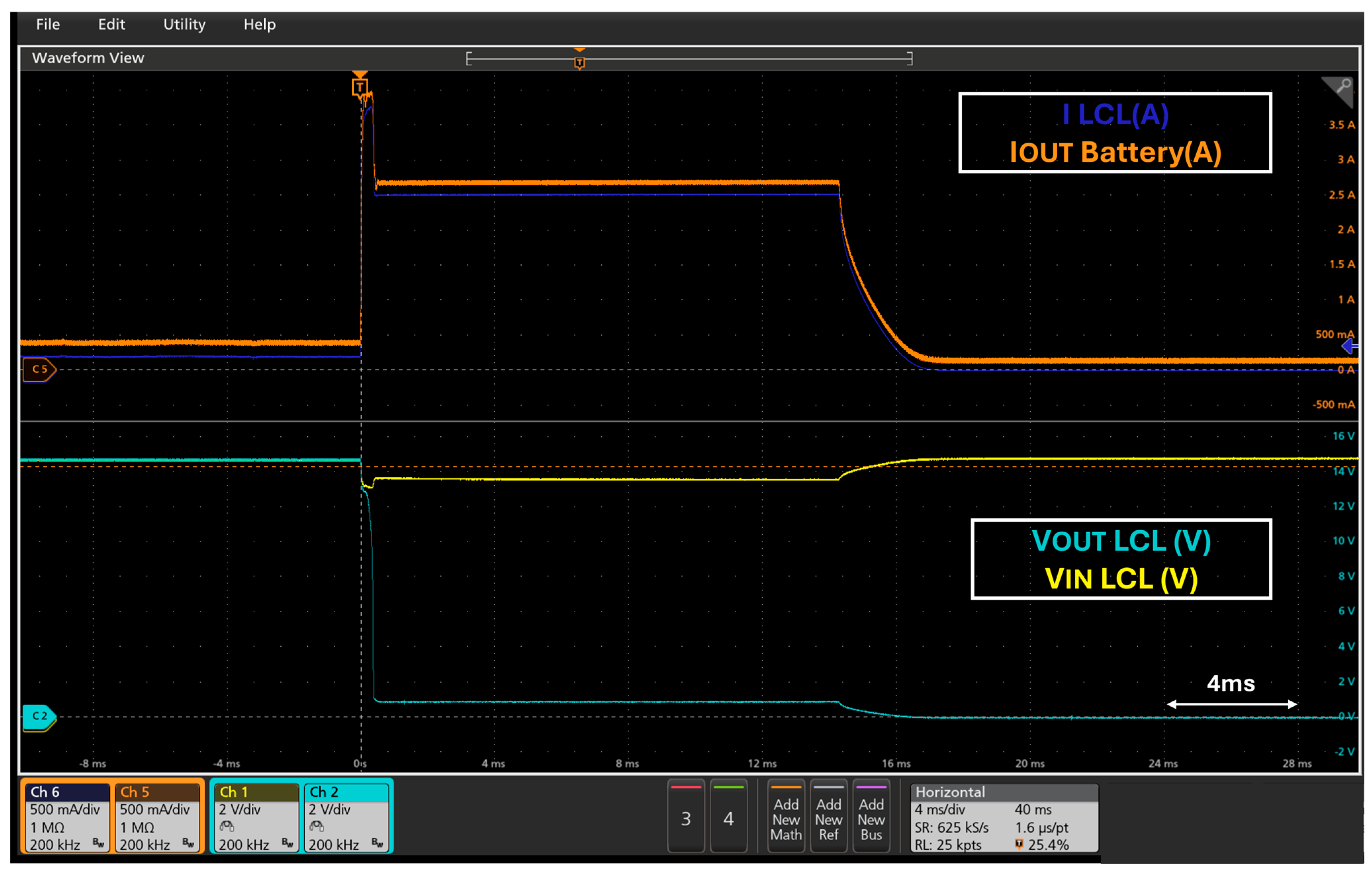
The operation of the Latch-up Current Limiter implemented in the unregulated PDU buses was verified. A current step from 0.2 A to 10 A was applied using a RIGOL DL3021A electronic load. Figure 10 shows a transient overshoot near 4 A for 0.5 ms upon the load step, after which the LCL limits the current to 2.7 A. After 14 ms of sustained overload, the device disconnects the output to protect the bus integrity.
Figure 10.
LCL behaviour on the PDU unregulated bus.
4.2. TID Radiation Tests
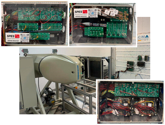
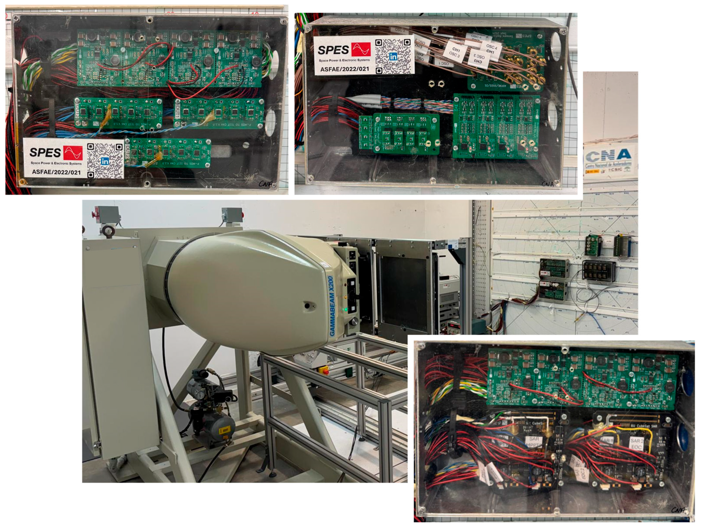
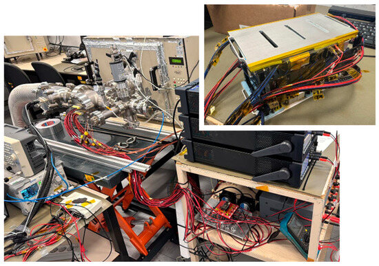
To validate the reliability of the COTS-based PCDU in high-radiation environments, TID campaigns were conducted at the National Accelerator Center. The performance of COTS components and modules was monitored in real-time under exposure to a Co-60 irradiator. Figure 11 shows the experimental setup.
Figure 11.
TID Test: Setup and Device Under Test (DUT).
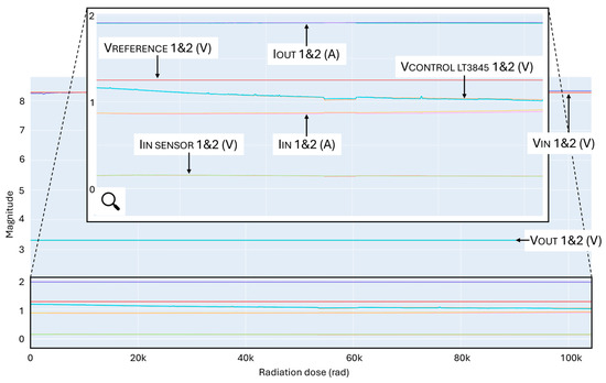
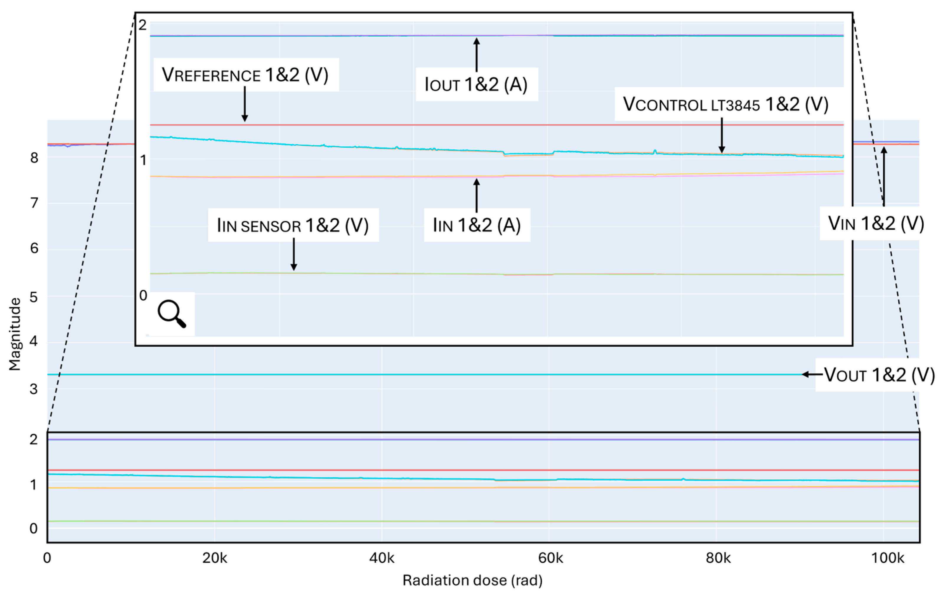
The Devices Under Test (DUTs) were irradiated without their aluminium enclosures at a dose rate of 0.2 kRad/h until exceeding a cumulative dose of 100 kRad. Figure 12 illustrates the evolution of the main signals for two independent buck converters and their ancillary electronic throughout the campaign. These buck converters have been implemented following the design philosophy presented in [20], where an external voltage control loop overrides the internal control loop of the LT3845 to enhance stability against radiation-induced effects. Regarding the experimental conditions, the converters were powered by a fixed voltage source at 8.4 V, while 1.8 Ω resistors were employed as a constant load. Despite an observed degradation in the LT3845 internal peak current control circuit, external control loops correctly compensate for this degradation, adapting the control voltage (VCONTROL_LT3845), maintaining a stable output voltage (VOUT) throughout the test. The proper functioning of voltage references (VREFERENCE) and input current sensors (IIN SENSOR) was also verified. Notably, these current sensors are required components of the satellite’s telemetry system, providing real-time operational data to the OBC. These tests validated both the electronic systems and the integrated batteries.
Figure 12.
TID test results.
4.3. TVAC Tests
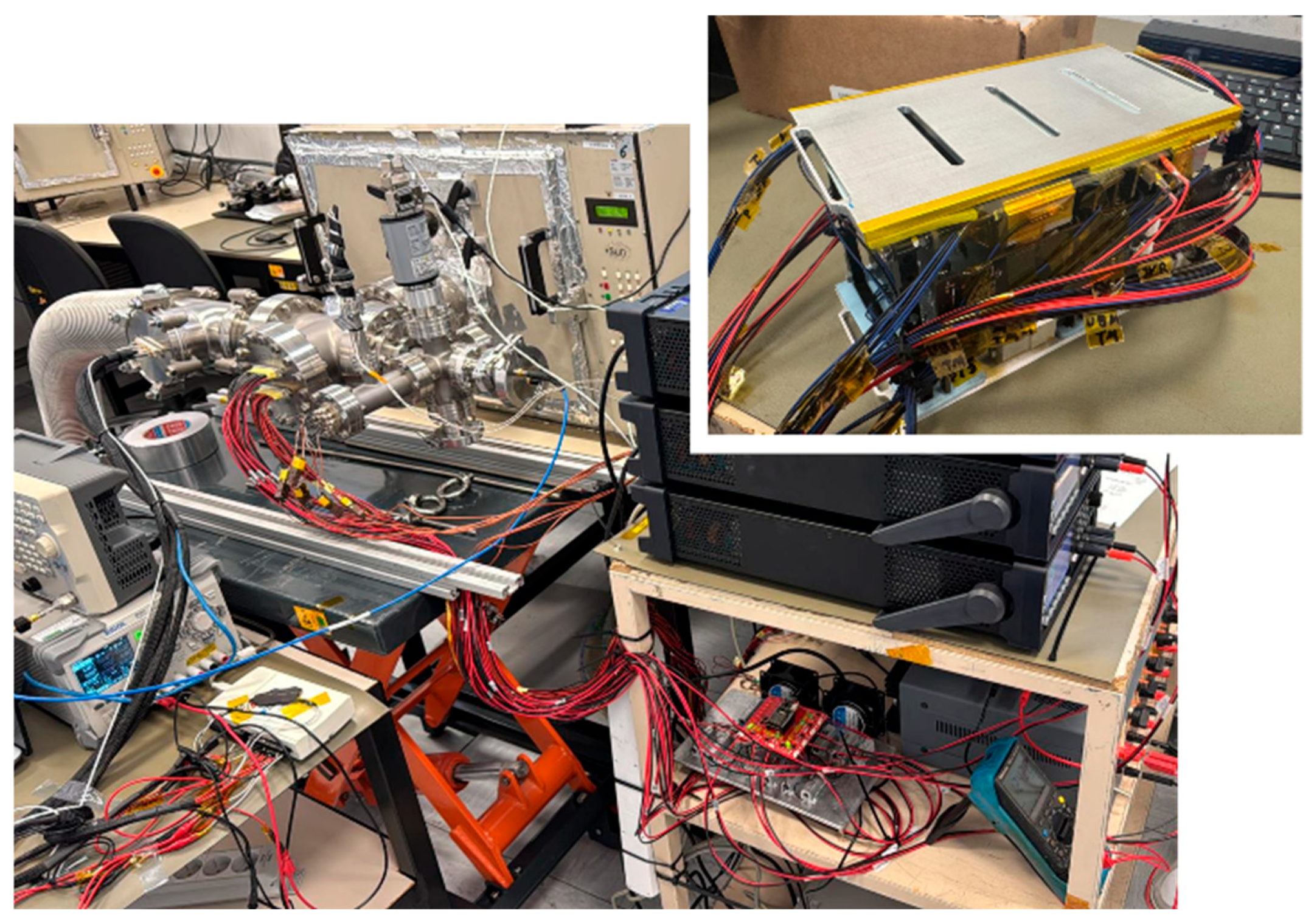
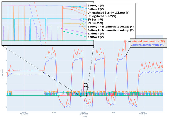
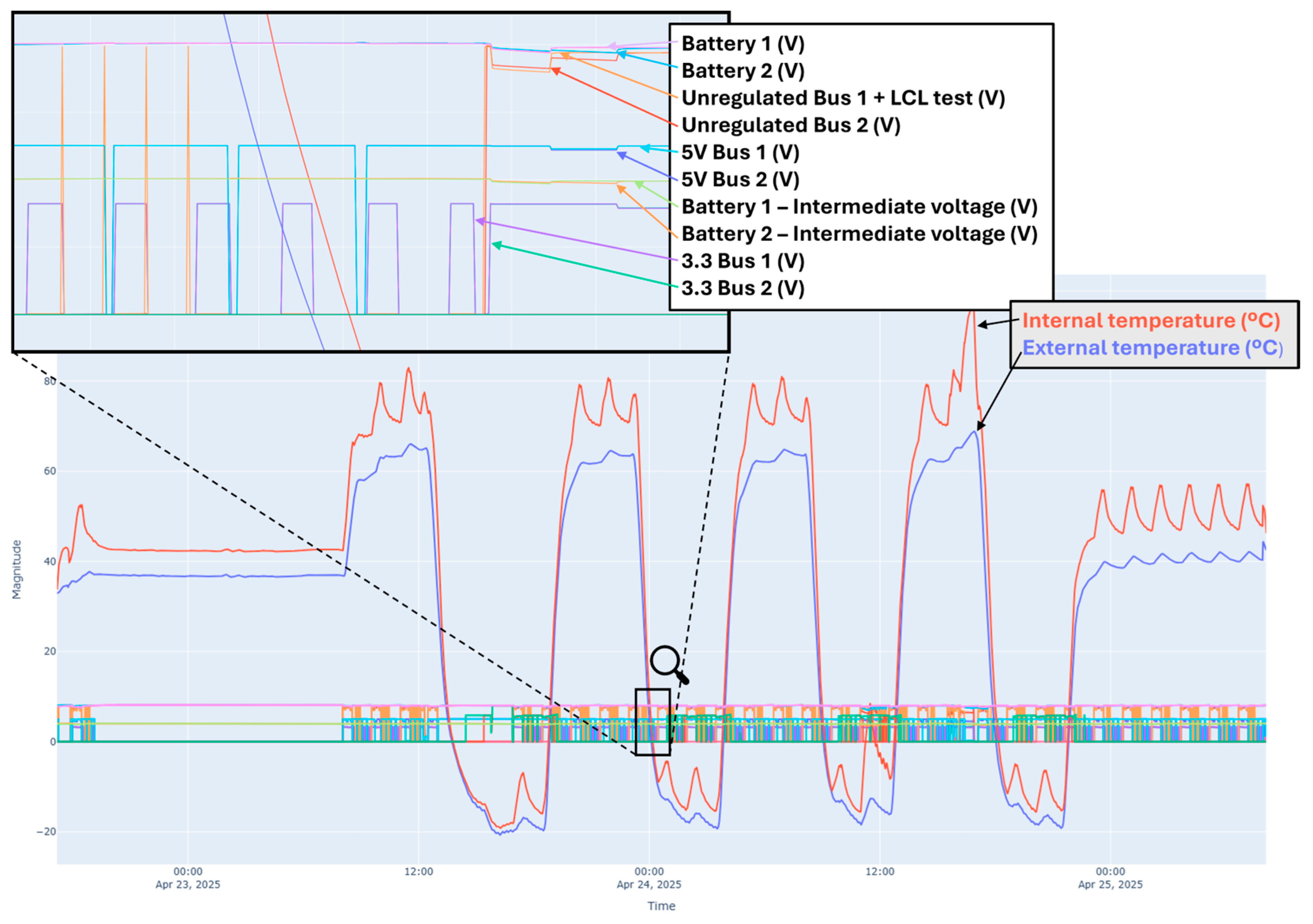
Thermal cycling under high-vacuum conditions was performed at the ALTER-Madrid facilities (see Figure 13). The campaign consisted of four thermal cycles between −20 °C and +60 °C over a period exceeding 48 h. To manage power dissipation within the compact enclosure, thermal shunts were implemented using high-conductivity materials and dedicated PCB copper planes to create low-resistance paths between critical components (such as power MOSFETs, diodes and inductors) and the chassis. During the tests, the PCDU’s thermal profile was monitored in real-time using eight temperature sensors distributed across various subsystems. The placement of these sensors was strategically determined based on previous experimental measurements conducted with a Fluke Ti450 infrared camera, which allowed for the identification of the primary localized hotspots along the main power path, including transistors and inductive elements. Critical PCDU signals were monitored in real-time under various load profiles, including overloads to validate LCL operation.
Figure 13.
TVAC Test—Setup and DUT.
Figure 14 shows part of the signals monitored during the test. The internal temperature of the PCDU remains above the external temperature due to power dissipation; however, no localized hotspots or temperatures exceeding the safety margins were detected, validating the effectiveness of the passive thermal control strategy. The power buses operated correctly under all load profiles. In addition to validating the electronics, the proper operation of the integrated batteries was verified, consolidating the design’s robustness for space missions.
Figure 14.
TVAC test results.
5. Conclusions
This paper has presented a modular architecture for a Power Conditioning and Distribution Unit, specifically designed to meet the scalability and reliability requirements of modern small satellites. The proposed modular approach enables the system to be adapted to diverse mission profiles by reconfiguring independent building blocks or modules.
The integration of COTS components in the design has achieved a disruptive reduction in development and manufacturing costs compared to traditional space-grade solutions, without compromising robustness or reliability. The design methodology, focused on fault tolerance and redundancy, has been validated through rigorous experimental campaigns. These tests confirm the PCDUs’ operational integrity under high-vacuum conditions and severe thermal cycling. Finally, radiation testing has demonstrated that the systems withstand cumulative radiation doses exceeding 75 kRad, a figure that establishes this PCDU as a highly competitive and reliable solution. However, as the unit is currently in an incremental development phase, specific testing for Single-Event Effects (SEEs) has not yet been conducted and remains as pending work for full space qualification. Consequently, it cannot be currently stated that the system possesses complete spatial radiation resistance. Nevertheless, the fully redundant architecture presented in this work has been designed with the intention of mitigating the potential impact of such single-particle events on mission performance. Furthermore, the design is prepared to handle potential SEE test failures by allowing the direct substitution of the most susceptible components (such as the LT3845 controller, operational amplifiers, and MOSFETs) with their Rad-Hard equivalents without requiring a circuit redesign.
Additionally, to further advance the reliability and redundancy of modular systems, future research could explore the integration of Wireless Power Transfer (WPT) as a means to eliminate mechanical stress and potential failure points in physical interconnections.
To conclude, the results obtained so far confirm that the unit is not only suitable for long-duration LEO missions but also positions itself as a highly promising platform for critical deep-space missions once the complete radiation validation process is finalized.
Author Contributions
Conceptualization, C.T.V., J.M.B.M. and A.G.S.; Methodology, C.T.V., J.M.B.M., A.G.S. and D.M.S.; Software, P.C.P. and J.L.L.M.; Validation, C.T.V., J.M.B.M., A.G.S., P.C.P. and J.L.L.M.; Formal analysis, C.T.V., A.G.S. and D.M.S.; Investigation, C.T.V., J.M.B.M., A.G.S., D.M.S. and P.C.P.; Resources, C.T.V., J.M.B.M. and J.L.L.M.; Data curation, P.C.P.; Writing—original draft, C.T.V.; Writing—review & editing, C.T.V., J.M.B.M., A.G.S. and D.M.S.; Visualization, C.T.V. and A.G.S.; Supervision, J.M.B.M. and A.G.S.; Project administration, J.M.B.M. and A.G.S.; Funding acquisition, J.M.B.M. and A.G.S. All authors have read and agreed to the published version of the manuscript.
Funding
This work has been funded by NextGenerationEU funds through the I+D+I program “Astrofisica y física de altas energías” of the European Union and the Generalitat Valenciana under reference number ASFAE/2022/21, and by the Generalitat Valenciana, the Valencian Innovation Agency, and the European Union through the “Fondo Europeo de Desarrollo Regional FEDER” under reference number INNEST/2023/143. The radiation tests conducted were made possible thanks to collaboration with the National Accelerator Center (CNA).
Data Availability Statement
The original contributions presented in this study are included in the article. Further inquiries can be directed to the corresponding author.
Conflicts of Interest
Please add the corresponding content of this part.
Abbreviations
The following abbreviations are used in this manuscript:
| AU | Astronomical Unit |
| BMS | Battery Management System |
| BOL | Beginning of Life |
| CNA | Centro Nacional de Aceleradores (National Accelerator Center) |
| COTS | Commercial Off-The-Shelf |
| DCX | Isolated DC-DC Converter (ZVZC topology) |
| DoD | Depth of Discharge |
| DSs | Deployment Switches |
| DUT | Device Under Test |
| EOC | End of Charge |
| FEDER/ERDF | European Regional Development Fund |
| FMECA | Failure Mode, Effects, and Criticality Analysis |
| LCL | Latch-up Current Limiter |
| LEO | Low Earth Orbit |
| MPP | Maximum Power Point |
| MPPT | Maximum Power Point Tracker |
| OBC | On-Board Computer |
| PCDU | Power Conditioning and Distribution Unit |
| PDU | Power Distribution Unit |
| RBF | Remove Before Flight |
| RLCL | Resettable Latch-up Current Limiter |
| SAR | Solar Array Regulator |
| SEEs | Single-Event Effects |
| SPFF | Single Point Failure Free |
| TID | Total Ionizing Dose |
| TM/TC | Telemetry and Telecommand |
| TVAC | Thermal Vacuum |
| WPT | Wireless Power Transfer |
| ZVZC | Zero Voltage Zero Current |
References
- Sweeting, M.N. Modern Small Satellites-Changing the Economics of Space. In Proceedings of the IEEE; IEEE: New York, NY, USA, 2018; Volume 106, pp. 343–361. [Google Scholar] [CrossRef] [Scilit]
- Bouzoukis, K.P.; Moraitis, G.; Kostopoulos, V.; Lappas, V. An Overview of CubeSat Missions and Applications. Aerospace 2025, 12, 550. [Google Scholar] [CrossRef] [Scilit]
- Klesh, A.; Krajewski, J. MarCO: CubeSats to Mars in 2016. In Proceedings of the 29th Annual AIAA/USU Conference on Small Satellites, Logan, UT, USA, 10–13 August 2015; Available online: https://digitalcommons.usu.edu/smallsat/2015/all2015/16/ (accessed on 8 February 2023).
- Goldberg, H.R.; Karatekin, Ö.; Ritter, B.; Herique, A.; Tortora, P.; Prioroc, C.; Gutierrez, B.G.; Martino, P.; Carnelli, I. The Juventas CubeSat in Support of ESA’s Hera Mission to the Asteroid Didymos. In Proceedings of the 33rd Annual AIAA/USU Conference on Small Satellites, Logan, UT, USA, 3–8 August 2015. [Google Scholar]
- Cicalò, S.; Alessi, E.M.; Provinciali, L.; Amabili, P.; Saita, G.; Calcagno, D.; Marcucci, M.F.; Laurenza, M.; Zimbardo, G.; Landi, S.; et al. Mission Analysis for the HENON CubeSat Mission to a Large Sun-Earth Distant Retrograde Orbit. Astrophys. Space Sci. 2025, 370, 83. [Google Scholar] [CrossRef] [Scilit]
- Sinclair, D.; Dyer, J. SSC13-IV-3 Radiation Effects and COTS Parts in SmallSats. In Proceedings of the 27th Annual AIAA/USU Conference on Small Satellites (SSC13), Logan, UT, USA, 4–9 August 2015. [Google Scholar]
- Langer, M.; Bouwmeester, J. Reliability of CubeSats—Statistical Data, Developers’ Beliefs and the Way Forward. In Proceedings of the AIAA/USU Conference on Small Satellites, Logan, UT, USA, 1–5 August 2016. [Google Scholar]
- Edpuganti, A.; Khadkikar, V.; El Moursi, M.S.; Zeineldin, H.; Al-Sayari, N.; Al Hosani, K. A Comprehensive Review on CubeSat Electrical Power System Architectures. IEEE Trans. Power Electron. 2022, 37, 3161–3177. [Google Scholar] [CrossRef] [Scilit]
- Zhang, W.; Xu, D.; Enjeti, P.N.; Li, H.; Hawke, J.T.; Krishnamoorthy, H.S. Survey on fault-tolerant techniques for power electronic converters. IEEE Trans. Power Electron. 2014, 29, 6319–6331. [Google Scholar] [CrossRef] [Scilit]
- Van Onno, N.W.; Doyle, B.R. Design Considerations and Verification Testing of an SEE-Hardened Quad Comparator. IEEE Trans. Nucl. Sci. 2001, 48, 1859–1864. [Google Scholar] [CrossRef]
- AAC Clyde Space. DataSheet: Starbuck-Nano. Available online: https://www.aac-clyde.space/wp-content/uploads/2021/11/AAC_DataSheet_Starbuck-Nano.pdf (accessed on 25 March 2026).
- GomSpace. Datasheet: NanoPower P60 Dock. Electric Power System for Nano Satellites. 2024. Available online: https://gomspace.com/wp-content/uploads/2025/09/gs-ds-nanopower-p60-dock-30.pdf (accessed on 25 March 2026).
- Di Tana, V.; Cotugno, B.; Simonetti, S.; Mascetti, G.; Scorzafava, E.; Pirrotta, S. ArgoMoon: There is a Nano-Eyewitness on the SLS. IEEE Aerosp. Electron. Syst. Mag. 2019, 34, 30–36. [Google Scholar] [CrossRef] [Scilit]
- Gutierrez, G.; Riccobono, D.; Bruno, E.; Bonariol, T.; Vigna, L.; Reverberi, G.; Fazzoletto, E.; Cotugno, B.; Vitiello, A.; Saita, G.; et al. LICIACube: Mission Outcomes of Historic Asteroid Fly-By Performed by a CubeSat. In Proceedings of the 2024 IEEE Aerospace Conference, Big Sky, MT, USA, 2–9 March 2024. [Google Scholar] [CrossRef] [Scilit]
- Edpuganti, A.; Khadkikar, V.; Zeineldin, H.; El Moursi, M.S.; Al Hosani, M. Comparison of Peak Power Tracking Based Electric Power System Architectures for CubeSats. IEEE Trans. Ind. Appl. 2021, 57, 2758–2768. [Google Scholar] [CrossRef] [Scilit]
- Torres, C.; Garrigós, A.; Blanes, J.M.; Casado, P.; Marroquí, D. Analog Maximum Peak Power Tracking Techniques for Small Satellites. IEEE Trans. Aerosp. Electron. Syst. 2023, 59, 6599–6611. [Google Scholar] [CrossRef] [Scilit]
- Selcan, D.; Kirbis, G.; Kramberger, I. Analog maximum power point tracking for spacecraft within a low earth orbit. IEEE Trans. Aerosp. Electron. Syst. 2016, 52, 367–378. [Google Scholar] [CrossRef] [Scilit]
- Barchowsky, A.; Amirahmadi, A.; Stell, C.; Merida, E.; Bolotin, G.; Carr, G. A Class of GaN-Based Radiation-Hardened Power Electronics for Jovian Environments. In Proceedings of the 2019 IEEE Applied Power Electronics Conference and Exposition, Anaheim, CA, USA, 17–21 March 2019. [Google Scholar] [CrossRef] [Scilit]
- Dabrowski, W.; Koperny, S.; Korba, A.; Stanecka, E.; Kotuła, J.; Godlewski, J.; Blocki, J. Development of radiation tolerant 48V/11V DC-DC converter for the ATLAS ITk Strip detector. In Proceedings of the TWEPP 2020 User Group Meetings, Online, 21–24 September 2020; Available online: https://indico.cern.ch/event/926254/contributions/3999448/ (accessed on 25 March 2026).
- Torres, C.; Blanes, J.M.; Garrigós, A.; Marroquí, D.; Carrasco, J.A. High-Reliability Solar Array Regulator for Deep Space Exploration Micro-Satellites. IEEE Access 2023, 11, 94138–94147. [Google Scholar] [CrossRef] [Scilit]
- Kohler, P.; Bosser, A.L.; Desdoits, D.; Vignon, G.; Garcia, P.; Wang, P.X. Total Ionizing Dose and Single Event Effect Test Results on Radiation Hardened By System DC-DC Power Converter. In 2023 RADECS Data Workshop, RADECS 2023; Institute of Electrical and Electronics Engineers Inc.: New York, NY, USA, 2023. [Google Scholar] [CrossRef] [Scilit]
- Torres, C.; Blanes, J.M.; Garrigos, A.; Marroqui, D.; Orts, C.; Carrasco, J.A. High-Reliability Solar Array Regulator Proposal for Harsh Environments. In Proceedings of the MELECON 2022—IEEE Mediterranean Electrotechnical Conference, Proceedings; IEEE: New York, NY, USA, 2022; pp. 698–702. [Google Scholar] [CrossRef] [Scilit]
- State of the Art: Small Spacecraft Technology 2022. California, Jan. 2023. Available online: https://www.nasa.gov/smallsat-institute/sst-soa (accessed on 20 February 2023).
- Casado, P.; Blanes, J.M.; Garrigós, A.; Marroquí, D.; Torres, C. Evaluation of commercial Li-Ion 18650 battery cells for deep space applications. J. Power Sources 2025, 638, 236552. [Google Scholar] [CrossRef] [Scilit]
- Casado, P.; Blanes, J.M.; Garrigós, A.; Marroquí, D.; Torres, C. COTS Battery Charge Equalizer for Small Satellite Applications. Appl. Sci. 2025, 15, 8228. [Google Scholar] [CrossRef] [Scilit]
- Knorr, W. Power System of METEOSAT Second Generation. In Proceedings of the 5th European Space Power Conference (ESPC); ESA: Tarragona, Spain, 1998; p. 11. [Google Scholar]
- Weinberg, A.H.; Ghislanzoni, L. A New Zero Voltage and Zero Current Power-Switching Technique. IEEE Trans. Power Electron. 1992, 7, 655–665. [Google Scholar] [CrossRef] [Scilit]
- Delepaut, C.; Kuremyr, T.; Martin, M.; Tonicello, F. LCL Current Control Loop Stability Design. In Proceedings of the European Space Power Conference 2014; ESA Publications Division: Noordwijkerhout, The Netherlands, 2014; pp. 15–17. [Google Scholar]
- Neubert, T.; Rongen, H.; Froehlich, D.; Schardt, G.; Dick, M.; Nysten, T.; Zimmermann, E.; Kaufmann, M.; Olschewski, F.; van Waasen, S. System-on-module-based long-life electronics for remote sensing imaging with CubeSats in low-earth-orbits. J. Appl. Remote Sens. 2019, 13, 032507. [Google Scholar] [CrossRef] [Scilit]
- Torres, C.; Blanes, J.M.; Garrigos, A.; Marroqui, D.; Carrasco, J.A. Single Point Failure Free Interleaved Synchronous Buck Converter for Micro Satellite Electrolysis Propulsion. IEEE J. Emerg. Sel. Top. Power Electron. 2022, 10, 5371–5380. [Google Scholar] [CrossRef] [Scilit]

Disclaimer/Publisher’s Note: The statements, opinions and data contained in all publications are solely those of the individual author(s) and contributor(s) and not of MDPI and/or the editor(s). MDPI and/or the editor(s) disclaim responsibility for any injury to people or property resulting from any ideas, methods, instructions or products referred to in the content. |
© 2026 by the authors. Licensee MDPI, Basel, Switzerland. This article is an open access article distributed under the terms and conditions of the Creative Commons Attribution (CC BY) license.