


Abstract
The aviation sector faces the challenge of reducing emissions while meeting growing demand for passenger transport. Recent research has proposed a hybridised axial compressor concept using a vaneless, counter-rotating configuration with independently electrically driven rotors. Earlier work showed the aerodynamic feasibility of this approach and identified the need for extended compressor maps to capture performance variations with hybridisation degree and speed ratio. This study explores the operational potential of such compressors in greater depth, focusing on how variable rotor speeds can unlock aerodynamic benefits and expand the operating envelope for hybrid-electric propulsion in regional aircraft and rotorcraft. Using mean line analysis, it is shown that independently driven rotors can operate effectively across a wide range of speed ratios. This flexibility enables the compressor to maintain high efficiency over diverse operating conditions, including part-load scenarios, typical of hybrid-electric missions. Independent speed control also offers a means of actively managing compressor stability. Compared to the conventional design the operating range can be significantly increased without relying on traditional stability measures such as variable stator vanes or bleed valves, reducing system weight and complexity. In this way the operating range of the hybrid compressor could be increased by up to 50%, while the number of blade rows could be reduced by up to 30% and the mass flow range increased by up to 33%. Together with the potential efficiency gains of counter-rotating concepts, this underscores its promise for future low-emission propulsion systems.
1. Introduction
Gas turbine propulsion systems have undergone decades of technological maturation, making further gains in efficiency and performance increasingly difficult to realise. Nevertheless, such gains have become more critical as the aviation sector works towards ambitious climate-policy targets. Meeting these objectives will likely require not only incremental improvements but also the exploration of concepts of more radical propulsion capable of operating efficiently under increasingly challenging regulatory constraints [1,2,3]. In parallel with the broader trend towards more electric aircraft, the integration of electrical components within the gas turbine has attracted growing interest. Hybrid-electric propulsion offers a promising pathway to boost or redistribute shaft power, enhance operability and enable degrees of freedom in design that are not accessible in conventional architectures [4].
2. Related Work
Regarding the placement of the electric machine and the specific engine component it supports, distinct hybridisation architectures have emerged. Isikveren et al. differentiate between concepts in which an electric motor is mechanically coupled to the fan or power shaft and architectures in which the core engine is electrically assisted, directly interacting with the thermodynamic cycle. The former are categorised as mechanically integrated parallel hybrids and the latter as cycle-integrated parallel hybrid (CIPH) [3]. In integrated CIPH concepts, the compressor rotors are fully electrically driven, allowing their rotational speed to be decoupled from that of the turbine and other stages. Seitz et al. examined various architectures in which an electric motor augments the gas turbine. Their findings indicate that redistributing a portion of the required power to electric machinery can achieve a double-digit percentage reduction in equivalent block emissions, assuming a 20% degree of hybridisation. The degree of hybridisation is defined as the supplied electric power divided by the supplied total power [5].
Hybridisation introduces options for innovative and more radical compressor designs, such as counter-rotating compressors, a concept first proposed in the mid-20th century. Up to this point, the adoption in aviation has been limited due to the complexities of mechanical integration, despite the potential advantages of such systems, including high pressure ratios and reductions in weight and length [6,7]. Vratny et al. highlight that CIPH concepts, which feature individually driven rotors, make counter-rotating stages particularly appealing as these are not mechanically linked to the turbine. This integration of electric machinery and rotor necessitates a unified design approach [8]. Alexiou et al. have modelled counter-rotating turbomachinery components for performance simulations, identifying the speed ratio as a key parameter influencing compressor performance [9]. Originally defined as the spool speed ratio between two shafts, this paper redefined as the ratio of the tip speed of the counter-rotating rotor to that of the co-rotating rotor.
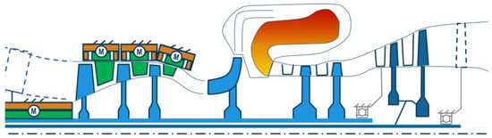
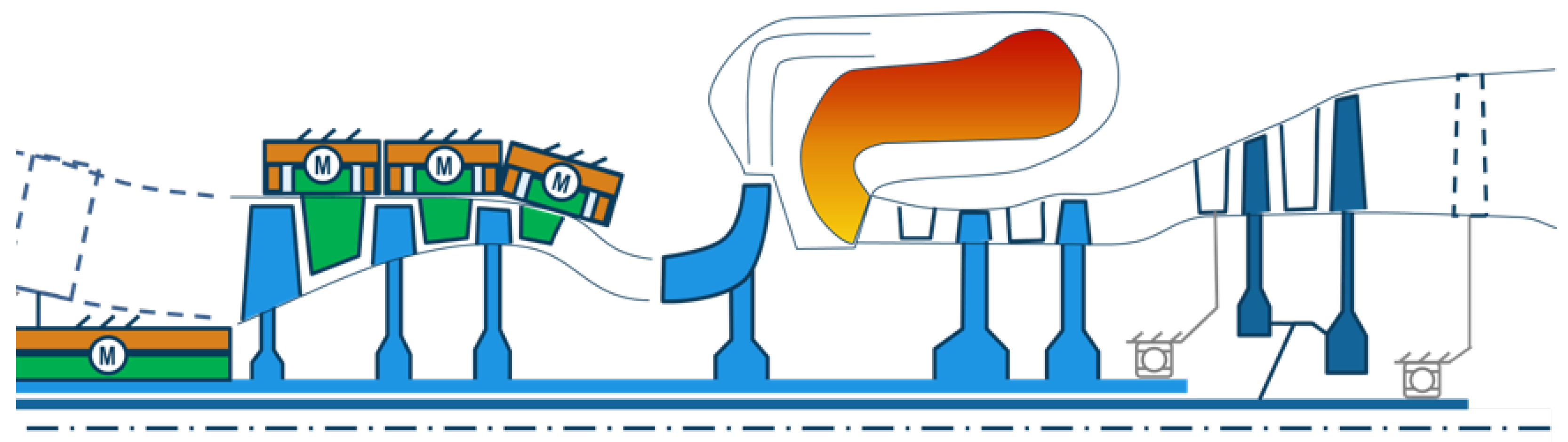
Since rotors can be operated independently, conventional stabilisation measures such as variable stator vanes, variable inlet guide vanes or handling bleed valves may be omitted. Instead, the rotor speeds can be adjusted to achieve the same effect. This approach allows the incidence to be controlled through rotor speed rather than by altering the stagger angle. Banjac and Petrovic proposed an efficient methodology for rapidly designing multi-stage axial compressors in conventional rotor-stator configuration, noting that analysis at mean radius is sufficient to conform operability across a wide range of conditions [10]. While Alexiou et al. demonstrated adaptations for analysing counter-rotating compressors at mean radius, their work did not account for variable rotor speeds over a wider range or the integration of electric components [9]. One example for the use of counter-rotating rotor rows within an axial compressor is currently under investigation within the LuFo-founded research project Hybridisierte Verdichterkonzepte (HybVer) engl. hybridised compressor concepts at TU Berlin. To explore the design space of cycle-integrated hybrid concepts, Maas et al. have previously assessed their effects at the engine and aircraft level and were able to demonstrate a significant reduction in power specific fuel consumption [11]. Figure 1 shows a conceptual illustration by Mass et al. of a possible cycle-integrated hybridised propulsion system with a counter-rotating axial compressor and individually driven counter-rotating rotors. At TU Berlin a modelling framework for axial compressor design and operability evaluation was described in an earlier publication [12]. Based on this, the present report investigates the possibility of cycle integrated hybridisation on compressor basis in more depth. It features the modelling results and performance of hybridised axial compressors, when conventional stability measures are not employed. The analysis compares hybridised engine concepts for regional (REG) and helicopter (HEL) aircraft against a conventional baseline, including both gas path pre-design and evaluating compressor performance. For the hybridised architectures the lower achievable tip speed ratio is assessed with and without flow deflection at the compressor inlet. Engine and compressor requirements were derived from specifications defined by Maas et al. [11]. The methodological approach for the aerodynamic pre-design of the compressor is briefly reviewed before presenting performance trends and implications for future hybridised compressor concepts.
Figure 1.
Conceptual illustration of a hybridised propulsion system with counter-rotating axial compressor [11].
3. Methods
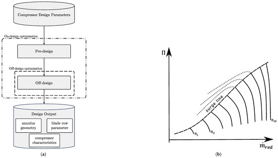
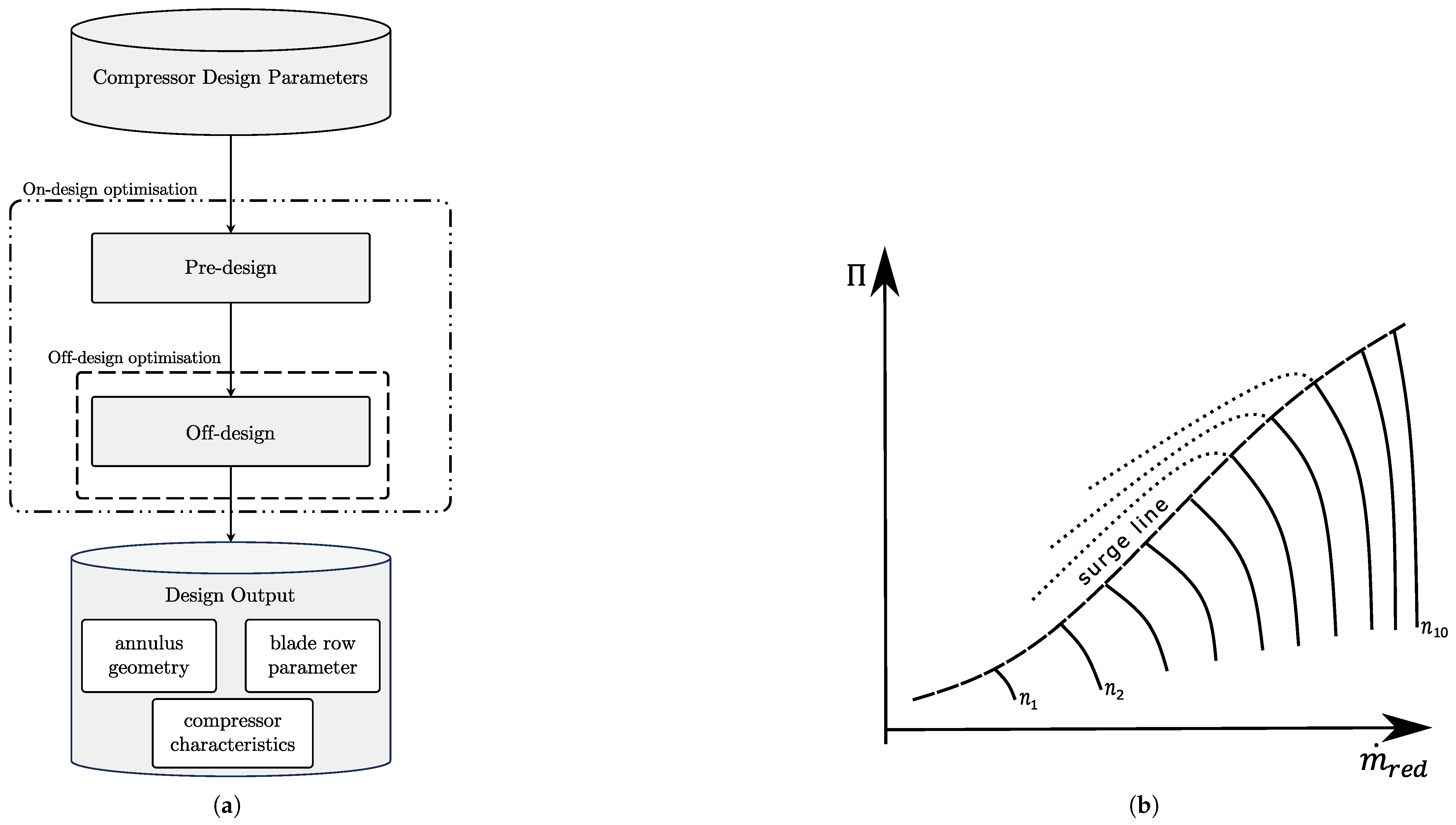
Figure 2 shows a general depiction of the applied toolchain where the pre-design was initially conducted, which resulted in gas path and blade row geometries for the design point. The results of the pre-design were then used to calculate the off-design performance using an in-house mean line solver, which is based on the work of Neumann and Peitsch [13]. The compressor design toolchain and modelling approach for hybridised compressor concepts has been presented in more detail in a previous publication [12]. Here a set of input design parameters is used to begin gas path pre-design, shown in Table 1. Based on these parameters, together with boundary conditions like target loading, the de Haller number or user-defined velocity components, annulus and blade geometry are solved row after row. The compressor map is generated by running the solver for a multitude of operating points, each operating point being a combination of corrected mass flow and corrected spool speed. The speed range is limited to 60% to 110% corrected spool speed. The definition of both corrected parameters are adopted from Kurzke and Halliwell [14]
The resulting pressure ratio and isentropic efficiency for each corrected speed line ( together with the corresponding corrected mass flow are displayed in a compressor performance map. Figure 2 shows a generic example of a compressor map to illustrate the solver behaviour if no abort criterion is implemented.
Figure 2.
(a) Flowchart of compressor design toolchain. (b) An example of a generic compressor map.
Table 1.
Input design parameter.
Up to a certain point, throttling leads to an increased pressure ratio, visualised by the solid lines. Further decreasing the corrected mass flow leads to lower pressure ratio without the solver aborting, indicated by the dotted line. Especially when the pressure ratio starts to drop, the results are assumed to be of numerical nature, and physically the compressor flow is already unstable or past the surge line [15]. Therefore, when solving the operating points the simulation is interrupted as soon as the maximum pressure ratio is reached and continues with the calculation of the next speed line. This can also be seen as an initial stability criterion, which considers the compressor as a whole. To investigate the stability in more detail an additional stability criterion is used. Here, the stall and choke incidence angles are evaluated at each blade row to gain more precise insights into compressor stability. The stall and choke incidence angle were estimated during pre-design for each blade row according to Cetin et al. [16].
is the modified version of the minimum loss incidence angle correlation from NASA SP-36 and the minimum design loss coefficient is obtained using the correlation provided by Koch and Smith [17,18]. The value for coefficient is obtained from Table 1 in Cetin et al. for the MCA blade profile type [16]. The incidence at each blade row, calculated during mean-line analysis, is compared to the corresponding stall and choke incidence angles. If the incidence of the airflow entering the blade row surpasses the stall incidence limit, the airflow cannot follow the aerofoil and separates, leading to high losses and the inability to increase pressure. In a multi-stage compressor, this can lead to a surge event where the intended flow direction can no longer be maintained and the built-up pressure is discharged via the compressor inlet.
If the incidence of airflow entering the blade row undershoots the choke incidence limit, the blade passage chokes. Therefore, if the incidence angle at a any operating point is either larger/smaller than the stall/choke incidence angle at any blade row, the compressor is regarded as not stable in this operating point. If the incidence angle is between the two incidence limits in every blade row, the operating point is regarded as stable.
4. Results
This section is subdivided into two parts, where results for regional aircraft and helicopter are shown separately. An overview of the selected top-level aircraft requirements is summarised in Table 2.
Table 2.
Top-level aircraft requirements for the regional aircraft and helicopter application [11].
Both the conventional and the hybridised architecture are designed to meet identical requirements. However, the additional components like batteries, cables and power electronics necessary in the hybridised propulsion system result in an increased aircraft mass, which in turn elevates thrust demands on the propulsion system. Consequently this alters the requirements for engine components, explaining the different specifications for the compressor in conventional versus hybridised propulsion systems. First results of the gas path pre-design are shown for the a conventional and hybridised propulsion system in each subsection. Afterwards the evaluation of operating characteristic in the form of compressor performance map is shown for both designs. With the variation in the tip speed ratio, the hybrid compressor performance changes. Therefore, an individual map exists for each tip speed ratio value. For clarity, only a selection of maps is included for each application illustrating compressor performance. The initial map in the selection represents the performance map for the tip speed ratio in the design point. The effect of varying the tip speed ratio is shown for a lower and higher tip speed ratio value. Lastly the effect of flow deflection at the compressor inlet on the lower boundary of the tip speed ratio value is evaluated.
4.1. Regional Aircraft
This section presents results for the regional aircraft application. In Table 3 necessary top-level design parameters for conducting the aerodynamic pre-design for the conventional and hybrid compressor concept are given. The values are derived from preliminary propulsion system sizing studies for the conventional and hybridised regional aircraft. These studies take into account changes on the aircraft level resulting from integrating additional components for hybridisation [11]. Furthermore, the architecture for both designs (conventional and hybridised) does not include traditional stability measures such as variable stator vanes, variable inlet guide vane or handling bleed valves.
Table 3.
Input parameter set for the conventional and hybrid regional aircraft.
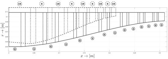
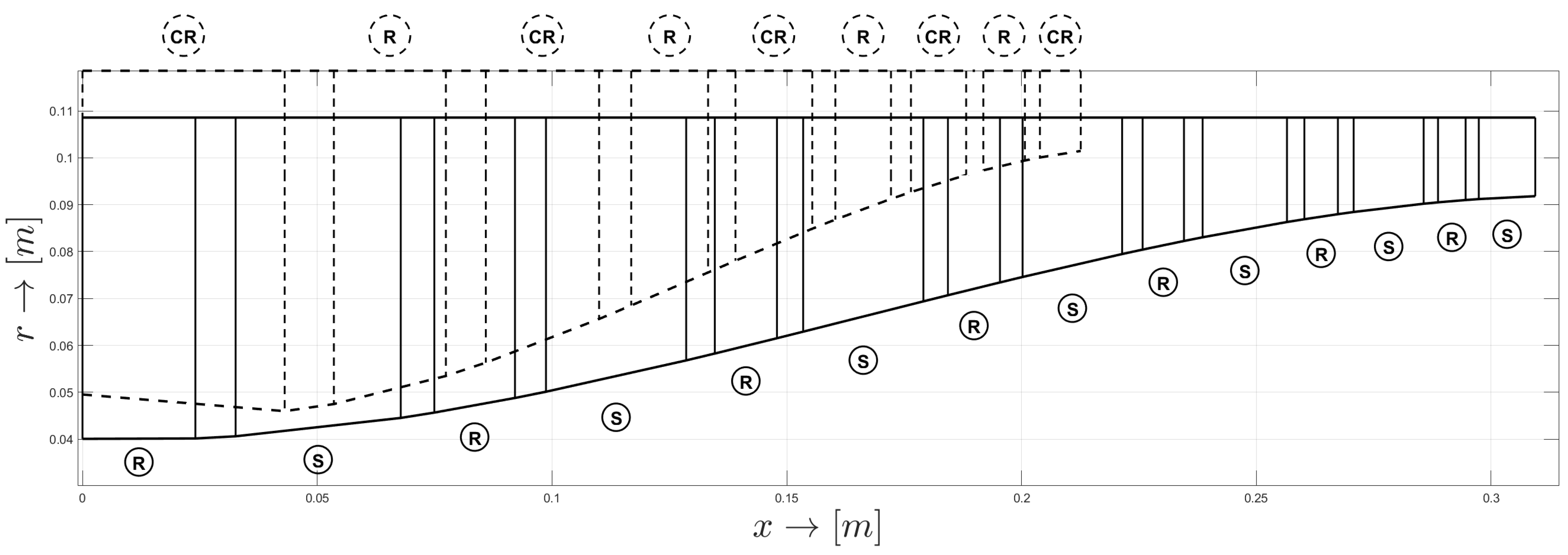
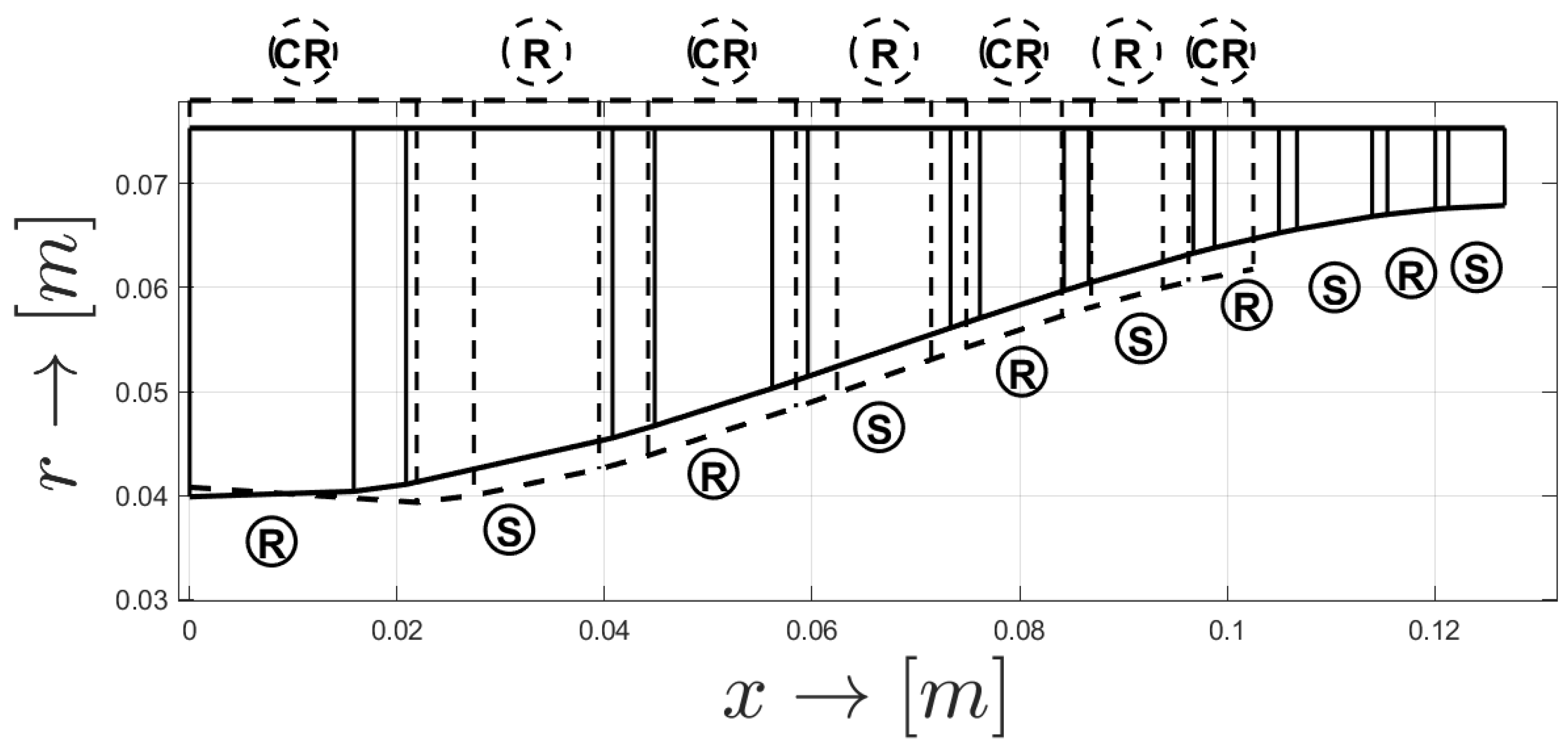
Figure 3 shows the results of the compressor gas path pre-design for the conventional compressor with solid lines and hybrid with dashed lines. The blade row arrangement is indicated by the circled letters.
Figure 3.
Gas path pre-design results of the conventional (solid) and hybrid (dashed) compressor for the regional aircraft application.
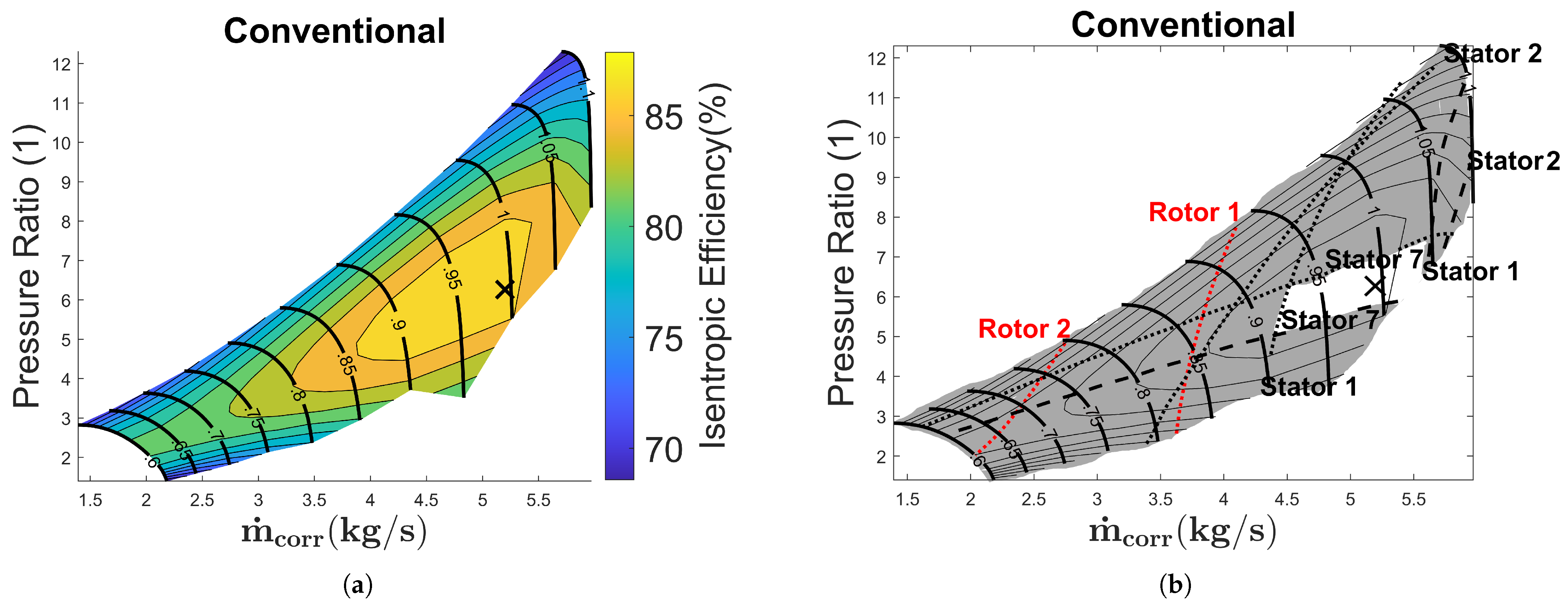
The resulting number of blade rows for the conventional design is 14 and reduced to 9 for the hybrid design. The isentropic efficiency was increased from 0.87 to 0.89 in the design point. The evaluation of the conventional compressor pre-design for multiple operating points for for the regional aircraft is shown in Figure 4.
Figure 4.
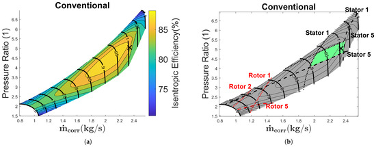
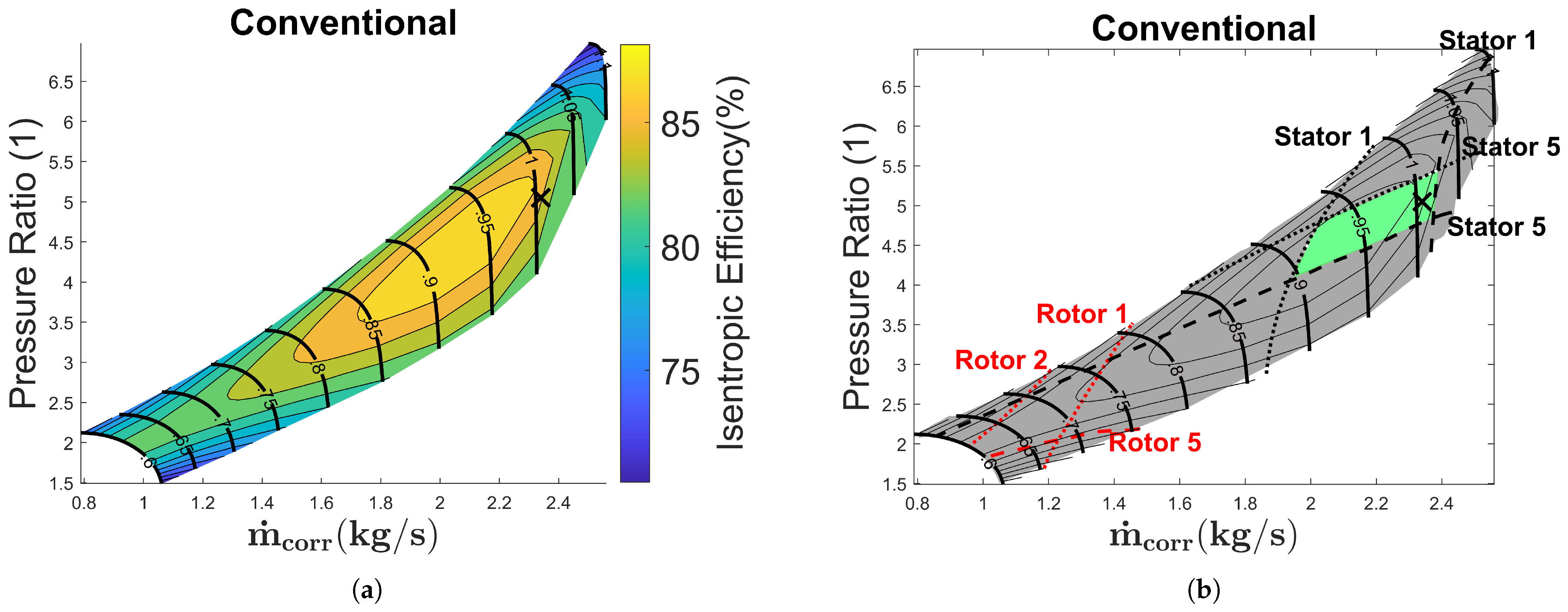
Compressor map of the conventional compressor for the regional aircraft. (a) Coloured contour map for conventional compressor. (b) Contour map with stability limit.
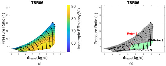
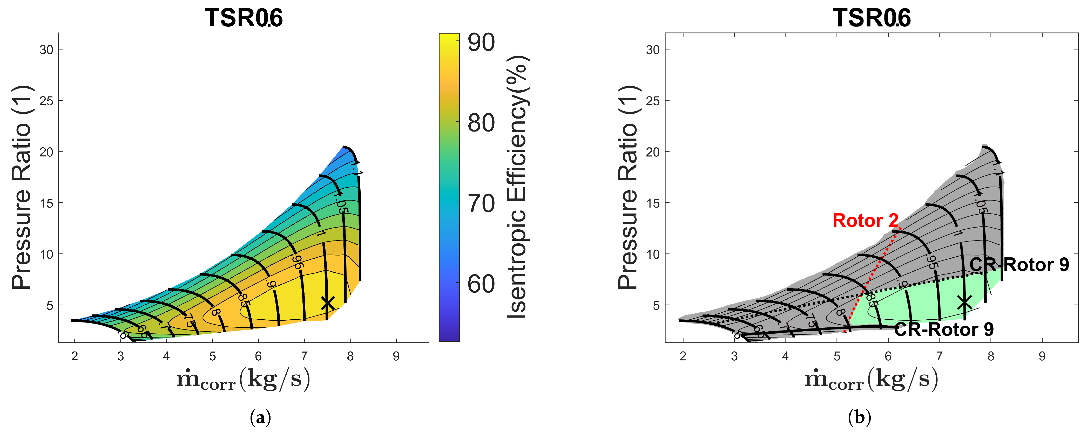
The left side shows the contour map for the conventional design. It illustrates the results of the meanline analysis with the initial stability criterion of the maximum pressure rise. As previously mentioned a second stability criterion is used to further assess stability. On the right side the incidence is used to evaluate the compressor stability. This allows limits to be set for each blade row. In Figure 4b multiple additional lines are drawn, indicating these limits for the respective blade row. The dotted line is the stall incidence limit and the dashed line the choke incidence limit. All operating points left of the dotted line therefore exceed the stall incidence limit in this blade row. Similarly, all operating points to the right of the dashed line exceed the choke incidence limit. The incidence was analysed for all blade rows, but only lines for blade rows which first become unstable are drawn. To emphasise this the stall incidence limit of rotors 1 and 2 are added as an exception, indicated by the dotted lines in red. The graphic indicates that the operating range is solely limited by the stator rows. The greyed-out area highlights the area where the incidence limit is exceeded in at least one rotor row, with a minimum and maximum corrected mass flow where no limit is exceeded of 4.40 and 5.53, respectively. If these are related to the design value of 5.45, this results in a minimum and maximum relative value of 0.81 and 1.03. It is evident that the conventional compressor is significantly limited in its operating range. This is to be expected as no traditional stability mechanisms are used. In Figure 5 the evaluation of multiple operating points for the hybrid compressor pre-design for the regional aircraft with a tip speed ratio of 0.6 is shown. As for the previous figure, the left side shows the contour map for the hybrid design. It illustrates the results of the meanline analysis for a tip speed ratio of 0.6 with the initial stability criterion of the maximum pressure rise. As for the conventional design, on the right side the incidence stability criterion is evaluated. Because of its counter-rotating configuration the hybrid compressor contains only rotor blade rows and no stator vanes. Thus, the distinction between the co- and counter-rotating rotors in Figure 5b is indicated by the CR prefix. For the design tip speed ratio the operating range is limited by the second (co-rotating) and last (counter-rotating) blade row. As in the previous figure the greyed-out area highlights the area where the incidence limit is exceeded in at least one rotor row. In addition the area marked in green indicates that no rotor row is exceeding an incidence limit. For the hybrid compressor, a tip speed ratio of 0.6 results in a minimum and maximum corrected mass flow of 5.17 and 8.21. In relation to the design value of 7.51, this results in a minimum and maximum relative value of 0.69 and 1.09. Operating the compressor with different tip speed ratios affects these limits. The effects of varying the tip speed ratio are shown in the following figures.
Figure 5.
Compressor map of the hybrid compressor for the regional aircraft with a tip speed ratio of 0.6. (a) Coloured contour map for hybrid compressor. (b) Contour map with stability limit.
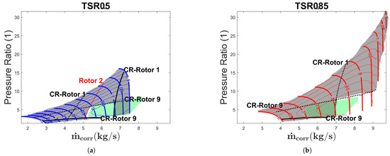
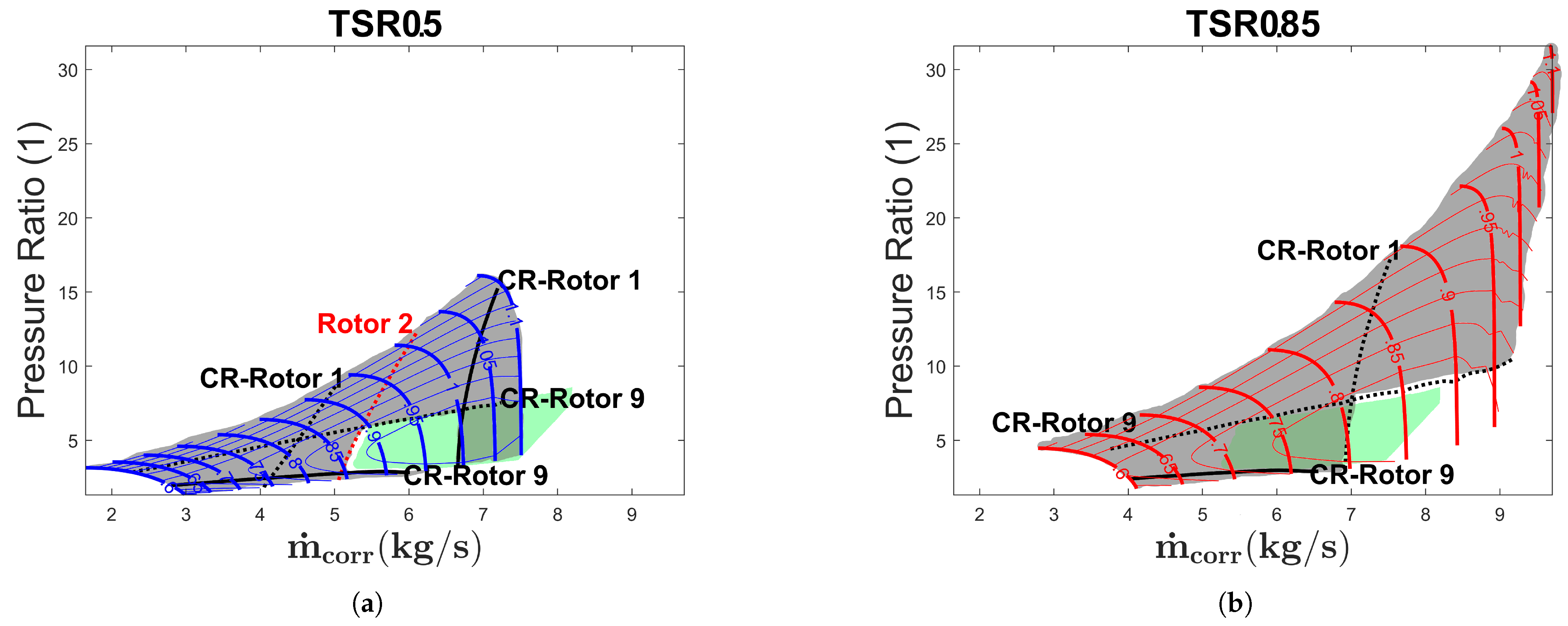
Figure 6 shows the performance map together with the stability limits for a tip speed ratio of 0.5 in blue and 0.85 in red. Furthermore, the green area from Figure 5b is also shown in order to help clarify the shift of stable operation in comparison to the map for a tip speed ratio of 0.6. Figure 6a shows that the operating range can be extended towards lower corrected mass flow, compared to the performance map for a tip speed ratio of 0.6. In absolute terms, the minimum value for the corrected mass flow changes to 5.14 and 0.68, respectively, to the design value. But this comes with a trade-off as the first rotor row (counter-rotating) is now limiting the range towards higher corrected mass flow, limiting the corrected mass flow to 6.72 or 0.89 expressed as the relative mass flow. A similar observation can be made in Figure 6b, where the operating range is extended towards higher corrected mass flow when increasing the tip speed ratio to 0.85. This increases the maximum corrected mass flow to 9.16 and the relative mass flow to 1.21. Likewise, the first rotor (counter-rotating) becomes limiting but towards lower corrected mass flow, and the second rotor (co-rotating) is no longer surpassing any incidence limit, limiting the minimum corrected mass flow to 6.92 or 0.92 in relative terms. Together, this corresponds to an increase in the range of relative mass flow in which no stability limit is exceeded of around 33% using variable tip speed ratios. Furthermore, adding the extended areas for the tip speed ratio of 0.5 and 0.85 increases the green area, where no incidence limit is exceeded, by about 50%. This indicates that in contrast to the conventional design, the tip speed ratio can be exploited to widen the range. The following considers the lower limit of the tip speed ratio where no stability limit is exceeded. Shown in Figure 7a is the performance map for lowest possible tip speed ratio of 0.4. Decreasing the tip speed ratio even further results in incidence limit violations for every operating point. Figure 7b,c show the effects on the lower possible tip speed ratio if the flow at the compressor inlet is deflected.
Figure 6.
Compressor map of the hybrid compressor for the regional aircraft with different tip speed ratios. (a) Tip speed ratio of 0.5 (b) Tip speed ratio of 0.85.
Figure 7.
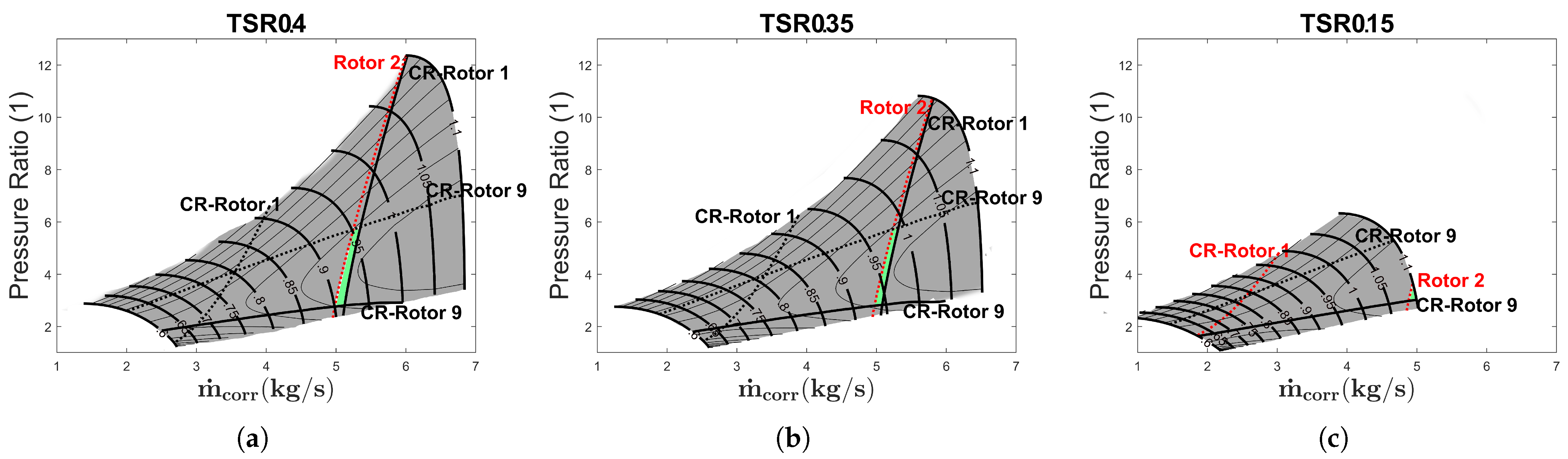
Lower possible tip speed ratio limit. (a) No flow deflection. (b) 5° flow deflection. (c) 30° flow deflection.
A deflection of 5° decreases the lower tip speed ratio limit to 0.35, and deflecting over 30° does not decrease the tip speed ratio lower than 0.15.
4.2. Helicopter
The same exercise was repeated for the helicopter application. As for the regional aircraft, Table 4 contains top-level design parameters necessary for conducting the aerodynamic pre-design for the conventional and hybrid compressor concept.
Table 4.
Input parameter set for the conventional and hybrid helicopter.
Figure 8 shows the results of the compressor gas path pre-design for the conventional compressor with solid lines and hybrid with dashed lines. The blade row arrangement is indicated by the circled letters.
Figure 8.
Gas path pre-design results of the conventional (solid) and hybrid (dashed) compressor for the helicopter application.
The resulting number of blade rows for the conventional design is 10 and reduced to 7 for the hybrid design. For both designs the efficiency is 0.88 in the design point. The evaluation of multiple operating points for the conventional compressor pre-design is shown in Figure 9.
Figure 9.
Compressor map of the conventional compressor for the helicopter. (a) Coloured contour map for conventional compressor. (b) Contour map with stability limit.
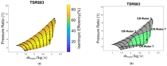
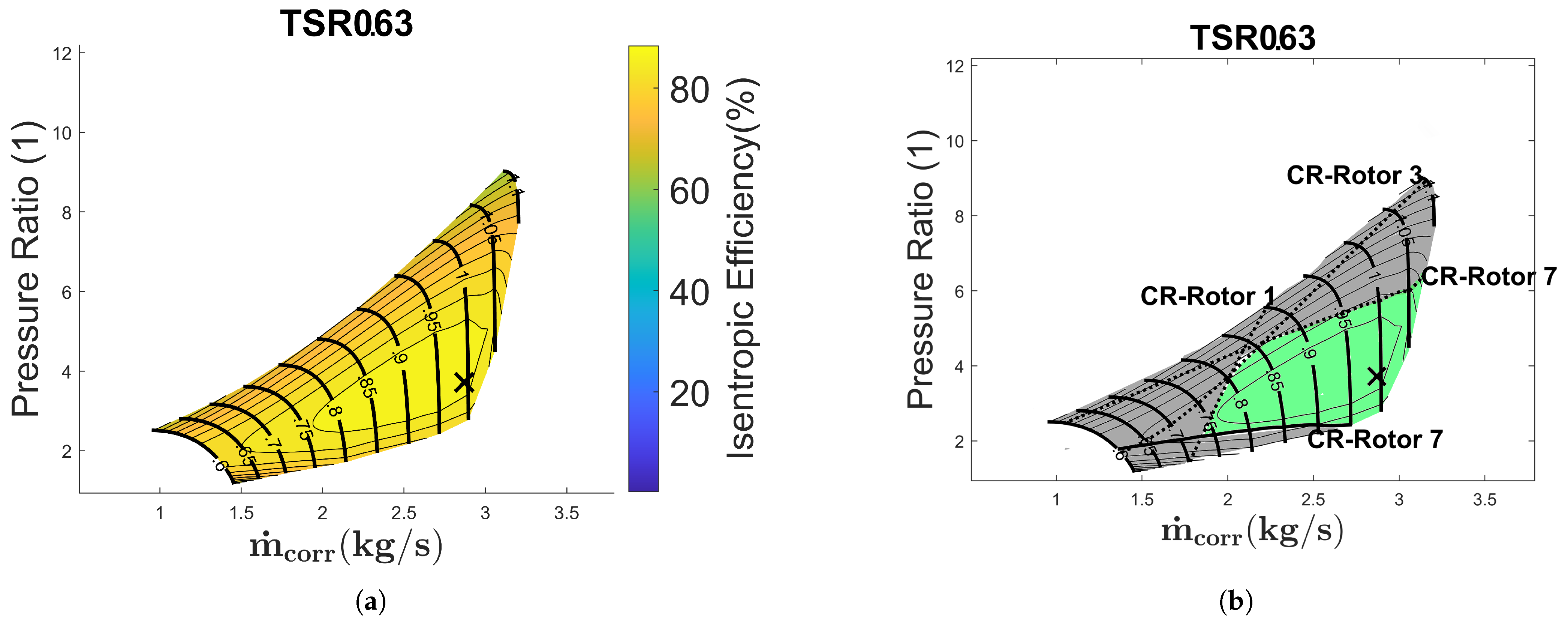
The left side shows the contour map for the conventional design. As for the regional aircraft the incidence is evaluated to assess compressor stability. Left of the dotted line, the stall incidence limit is surpassed, while right of the dashed line, the choke incidence limit is surpassed. Red indicates the limit of a rotor row and black of a stator row. Similar to the regional aircraft compressor, the area where no stability limit is exceeded is only limited by stator rows, with a minimum and maximum corrected mass flow of 1.94 and 2.39, respectively, and related to the design values of 2.35, 0.83 and 1.02. Thus, the helicopter compressor is limited in a similar way to the regional compressor. The evaluation of multiple operating points for the hybrid compressor pre-design and a TSR of 0.63 is shown in Figure 10. As in the previous figure, the left side shows the contour map for the hybrid design. On the right side the stability criterion is evaluated, with a minimum and maximum corrected mass flow of 1.84 and 3.1. This results in a minimum and maximum relative mass flow of 1.09 and 0.64, related to the design value of 2.87. This brings the mass flow range into a similar realm to that of the hybridised regional application. The effects of varying the tip speed ratio are shown in the following figures.
Figure 10.
Compressor map of the hybrid compressor for the helicopter with a tip speed ratio of 0.63: (a) Coloured contour map for hybrid compressor. (b) Contour map with stability limit.
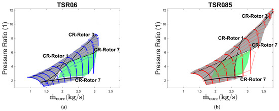
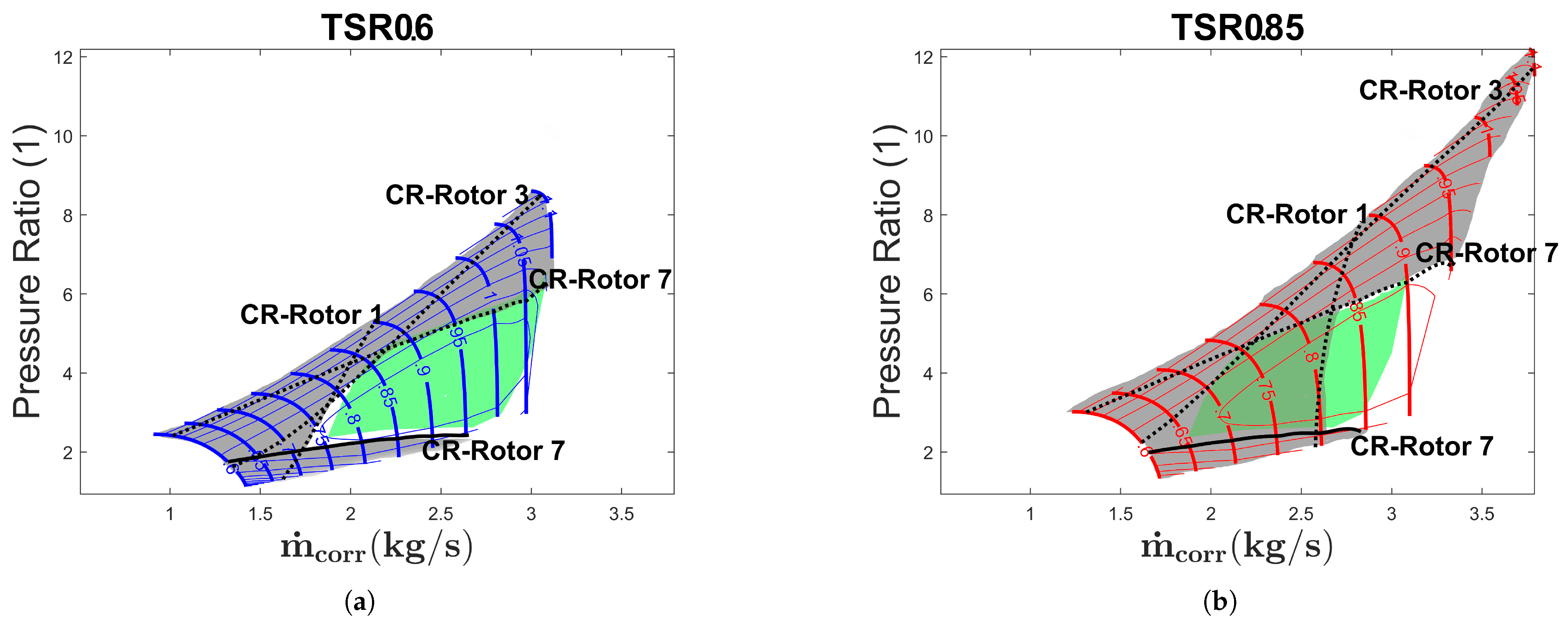
Figure 11 shows the performance map together with the stability limits for a tip speed ratio of 0.6 in blue and 0.85 in red. Figure 11a shows a similar trend, whereby a reduced tip speed ratio extends the performance map to lower corrected mass flows. The minimum corrected mass flow decreases from 1.84 to 1.73 and the minimum relative mass flow from 0.64 to 0.6. In contrast to the compressor for regional application, the first rotor row (counter-rotating) does not limit the range towards higher corrected mass flow. The upper limit of corrected mass flow for the tip speed ratio of 0.5 is 3.09 or 1.08 relative mass flow. Figure 11b, in turn, shows a similar pattern to that of the regional application. A higher tip speed ratio of 0.85 increases the maximum corrected mass flow from 3.14 to 3.33 or from 1.09 to 1.16 for the relative mass flow, as well as the limitation towards lower corrected mass flow by the first rotor row (counter-rotating) from 1.84 to 2.58. This is expressed in relative mass flow from 0.64 to 0.9. This increases the corrected mass flow range by about 24% and the area where no incidence limit is exceeded by about 40%.
Figure 11.
Compressor map of the hybrid compressor for the helicopter with different tip speed ratios. (a) Tip speed ratio of 0.6 (b) Tip speed ratio of 0.85.
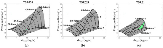
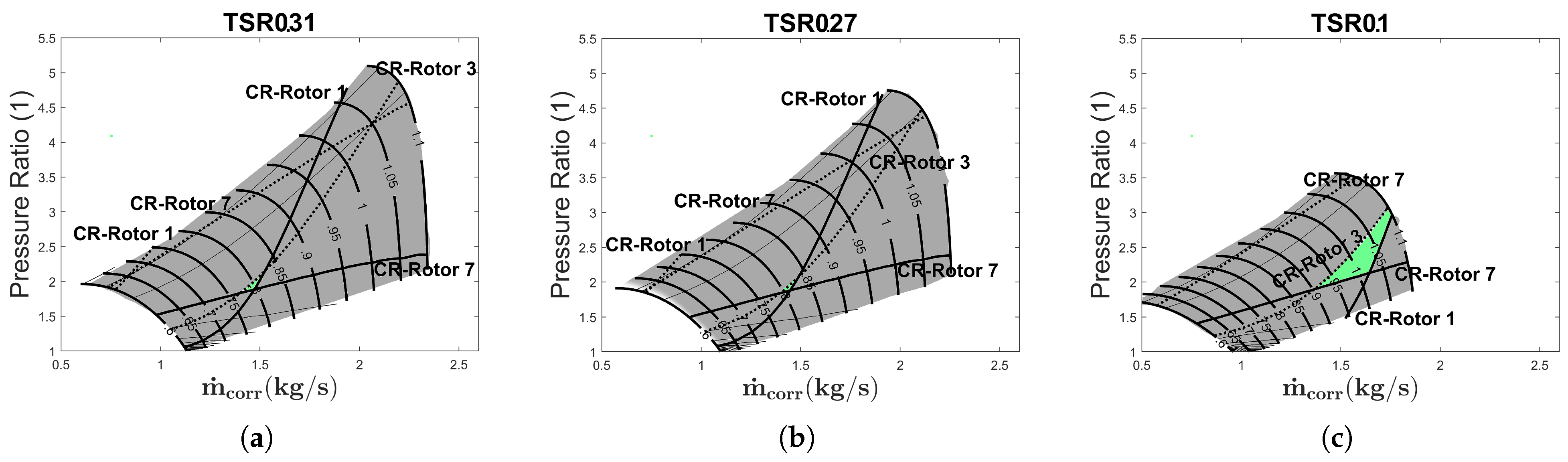
Again in Figure 12 inlet deflection is applied to assess the lower possible tip speed ratio. Subfigure (a) shows the first stable region for TSR 0.31 without deflection. A deflection of 5° decreases the lower TSR to 0.27, and deflecting over 30° does not decrease the TSR lower than 0.1.
Figure 12.
Lower possible tip speed ratio limit. (a) No flow deflection. (b) 5° flow deflection. (c) 30° flow deflection.
5. Discussion
Many of the publicly available empirical correlation methods used during mean line analysis are several decades old, and accurate numerical prediction of the surge limit is a challenge to this day [19]. As a result, the reliability of single individual numerical values is somewhat limited. Still, they are sufficient for estimating general performance trends. Thus, a regional aircraft switching to a counter-rotating configuration for the hybrid concept results in blade row reduction and potential efficiency gains. Regarding the blade row count, part of the reduction is due to the lower required pressure ratio for the hybrid concept. Still, the reduction holds true when accounting for this by adding a hypothetical single additional rotor with a pressure ratio equivalent to the 9th (number of blade rows) root of the target pressure ratio of 5.17 at the end of the hybrid compressor. This would bring the total pressure ratio of the hybrid axial compressor to a level comparable to that of the conventional compressor. Additionally, the potential to reduce the number of necessary blade rows is limited because of structural limits, which was described in earlier publications [12,20,21]. This refers primarily to the integration of electric motors, particularly concerning the permanent magnets as their limit for circumferential velocity is lower than that of the blade tip speed. Therefore, switching to a different approach for driving the counter-rotating blade rows offers the potential for further reduction in blade rows. Regarding the operating range of all compressor designs and comparing them to expected values from the literature, it is evident that the operating range is limited. Typically, relative speed for low power settings are around 60% of the design speed and relative mass flow below 50% of the design mass flow [22,23]. Especially for the relative speed, the presented results indicate that lower values from the literature cannot be reached. However, this can be explained by the absence of conventional stability mechanisms like variable inlet guide vanes, variable stator vanes and handling bleed valves. As mentioned in the beginning, this decision was made in order to be able to attribute the effect on the operating range to the tip speed variation alone. When considering the possible lower limit for the tip speed ratio, pressure losses, especially due to flow separation for high deflection, were not taken into account. Therefore, the absolute number for the lower tip speed ratio may differ, but it reveals the trend that deflection can significantly decrease the lower value. It also shows that the tip speed ratio cannot become zero. However, there is a lower limit that enables operation at reduced engine power. This lower limit can also be translated into a lower power demand on the electrical components. With regard to the design of electrical components, this is important information when designing its architecture regarding necessary redundancy as it indicates that a total failure of the electrical components will also lead to engine failure.
6. Conclusions and Outlook
The results indicate that the operating range is significantly widened when exploiting the tip speed ratio. For the regional application the relative mass flow range, without exceeding the limit, was increased by 33% and for the helicopter application by 24%. Also the number of blade rows can be reduced by up to 30% when switching to a counter-rotating configuration. It was indicated that deflection at the compressor inlet can increase the range to some extent, but the benefit should be weighed against the additional necessary variable inlet guide vane, especially whether similar results regarding the operating range could be achieved by reinstating handling bleed valves. Therefore, further studies regarding hybridised, counter-rotating axial compressors should focus on exploiting the tip speed ratio together with handling bleed valves, with the goal of reaching a comparable operating range of a conventional axial compressor equipped with variable stator vanes/variable inlet guide vane and handling bleed valves.
Author Contributions
All authors contributed to the study conception and design. The preparation of the used model, the data collection, as well as the analysis were performed by J.N. The first draft of the manuscript was written by J.N., and all authors commented on previous versions of the manuscript. All authors have read and agreed to the published version of the manuscript.
Funding
This work is funded by the BMWK (Federal Ministry for Economic Affairs and Climate Action of Germany) through Luftfahrtforschungsprogramm-VI (Grant number: 20E2111B).
Data Availability Statement
The datasets generated and analysed during the current study are available with restrictions from the corresponding author on reasonable request.
Conflicts of Interest
The authors have no competing interests to declare that are relevant to the content of this article.
References
- Air Transport Action Group. Waypoint 2050 2nd Edition: September 2021; ATAG: Geneva, Switzerland, 2021; Available online: https://atag.org/resources/waypoint-2050-2nd-edition-september-2021/ (accessed on 20 March 2026).
- IPCC—Intergovernmental Panel on Climate Change. Climate Change 2022—Mitigation of Climate Change: Working Group III Contribution to the Sixth Assessment Report of the Intergovernmental Panel on Climate Change; Cambridge University Press: Cambridge, UK, 2023. [Google Scholar] [CrossRef] [Scilit]
- Isikveren, A.; Pornet, C.; Vratny, P.; Schmidt, M. Conceptual Studies of Future Hybrid-Electric Regional Aircraft. In Proceedings of the 22nd International Symposium on Air Breathing Engines (ISABE), Phoenix, Arizona, 25–30 October 2015; Paper No. ISABE-2015-20285; ISABE: Indianapolis, IN, USA, 2015. [Google Scholar]
- European Union Aviation Safety Agency. European Aviation Environmental Report 2025; Publications Office: Luxembourg, 2025. [Google Scholar]
- Seitz, A.; Nickl, M.; Stroh, A.; Vratny, P.C. Conceptual study of a mechanically integrated parallel hybrid electric turbofan. Proc. Inst. Mech. Eng. Part G J. Aerosp. Eng. 2018, 232, 2688–2712. [Google Scholar] [CrossRef] [Scilit]
- Sharma, P.B.; Jain, Y.P.; Jha, N.K.; Khanna, B.B. Stalling Behaviour of a Contra-Rotating Axial Compressor Stage. In Proceedings of the 7th International Symposium on Air Breathing Engines (ISABE), Beijing, China, 2–6 September 1985; Paper No. 85-7087; ISABE: Indianapolis, IN, USA, 1985. [Google Scholar]
- Šajbanová, K.; Čerňan, J.; Škultéty, F.; Rostáš, J. Conceptual Design of the Axial Compressor Stage with Counter-Rotating Rotors. Transp. Res. Procedia 2021, 59, 144–153. [Google Scholar] [CrossRef] [Scilit]
- Vratny, P.C.; Kaiser, S.; Seitz, A.; Donnerhack, S. Performance Investigation of Cycle-Integrated Parallel Hybrid Turboshafts; American Society of Mechanical Engineers: New York, NY, USA, 2016. [Google Scholar] [CrossRef] [Scilit]
- Alexiou, A.; Roumeliotis, I.; Aretakis, N.; Tsalavoutas, A.; Mathioudakis, K. Modeling Contra-Rotating Turbomachinery Components for Engine Performance Simulations: The Geared Turbofan with Contra-Rotating Core Case. J. Eng. Gas Turbines Power 2012, 134, 111701. [Google Scholar] [CrossRef] [Scilit]
- Banjac, M.; Petrovic, M.V. Development of Method and Computer Program for Multistage Axial Compressor Design: Part I—Mean Line Design and Example Cases. In Proceedings of the ASME Turbo Expo 2018: Turbomachinery Technical Conference and Exposition, Oslo, Norway, 11–15 June 2018; p. V02CT42A007. [Google Scholar] [CrossRef] [Scilit]
- Maas, P.; Warsch, C.; Böck, R.; Kolb, M.; Seitz, A. Pre-Design Investigation of a Propulsion System with Compressor Electric Drive; Deutsche Gesellschaft für Luft- und Raumfahrt—Lilienthal-Oberth e.V.: Bonn, Germany, 2024. [Google Scholar] [CrossRef] [Scilit]
- Nittka, J.; Akkaya, M.; Neumann, N.; Peitsch, D. Aerodynamic Pre-Design and Performance Evaluation of Counter Rotating Hybridised Compressor Concepts: Modelling Approach. CEAS Aeronaut. J. 2025. [Google Scholar] [CrossRef] [Scilit]
- Neumann, N.; Peitsch, D. Introduction and Validation of a Mean Line Solver for Present and Future Turbomachines. In Proceedings of the 24th International Symposium on Air Breathing Engines (ISABE), Canberra, Australia, 22–27 September 2019; Paper No. ISABE-2019-24441; ISABE: Indianapolis, IN, USA, 2019. [Google Scholar]
- Kurzke, J.; Halliwell, I. Propulsion and Power; Springer International Publishing: Cham, Switzerland, 2018. [Google Scholar] [CrossRef] [Scilit]
- Haeckel, T.; Paul, D.; Leichtfuß, S.; Schiffer, H.P.; Eißler, W. Determination of a Numerical Surge Limit by Means of an Enhanced Greitzer Compressor Model. Int. J. Turbomach. Propuls. Power 2023, 8, 48. [Google Scholar] [CrossRef] [Scilit]
- NATO (Ed.) Application of Modified Loss and Deviation Correlations to Transonic Axial Compressors. In Number 745 in AGARD Conference Proceedings; AGARD: Neuilly-sur-Seine, France, 1987. [Google Scholar]
- Johnson, I.A.; Bullock, R.O. Aerodynamic Design of Axial Flow Compressors; National Aeronautics and Space Administration: Washington, DC, USA, 1965. [Google Scholar]
- Koch, C.C.; Smith, L.H. Loss Sources and Magnitudes in Axial-Flow Compressors. J. Eng. Power 1976, 98, 411–424. [Google Scholar] [CrossRef] [Scilit]
- Hergt, A.; Klinner, J.; Wellner, J.; Willert, C.; Grund, S.; Steinert, W.; Beversdorff, M. The Present Challenge of Transonic Compressor Blade Design. J. Turbomach. 2019, 141, 091004. [Google Scholar] [CrossRef] [Scilit]
- Schreer, L.; Gümmer, V. Preliminary Thermal Management System Design for Cycle-Integrated Parallel Hybrid Compressors. CEAS Aeronaut. J. 2025. [Google Scholar] [CrossRef] [Scilit]
- Yang, Y.; Möhlenkamp, G. Sizing and Parameter Study of Compressor Case-Mounted Permanent Magnet Synchronous Motor for Hybrid Electrical Compressor Integration; Deutsche Gesellschaft für Luft- und Raumfahrt—Lilienthal-Oberth e.V.: Bonn, Germany, 2024. [Google Scholar] [CrossRef]
- Bräunling, W.J.G. Flugzeugtriebwerke: Grundlagen, Aero-Thermodynamik, ideale und reale Kreisprozesse, Thermische Turbomaschinen, Komponenten, Emissionen und Systeme, 4th ed.; Springer: Berlin/Heidelberg, Germany, 2015. [Google Scholar]
- Cumpsty, N.A. Compressor Aerodynamics; Krieger Pub: Malabar, FL, USA, 2004. [Google Scholar]

Disclaimer/Publisher’s Note: The statements, opinions and data contained in all publications are solely those of the individual author(s) and contributor(s) and not of MDPI and/or the editor(s). MDPI and/or the editor(s) disclaim responsibility for any injury to people or property resulting from any ideas, methods, instructions or products referred to in the content. |
© 2026 by the authors. Licensee MDPI, Basel, Switzerland. This article is an open access article distributed under the terms and conditions of the Creative Commons Attribution (CC BY) license.