


Abstract
This study presents the design and flight testing of a small unmanned aerial vehicle (UAV) in a flying wing configuration. The flying wing concept provides a low-drag platform suitable for observation, surveillance, and search-and-rescue missions. The UAV is designed to achieve inherent stability without the use of vertical stabilizers or artificial stabilization systems, which may reduce aerodynamic efficiency. The design process includes aerodynamic analyses aimed at balancing static and dynamic stability. Flight tests are conducted to validate the proposed configuration and to assess its ability to maintain stable flight under various operating conditions. The results confirm that the developed flying wing UAV achieves stable flight without artificial stabilization, demonstrating the potential of flying wing configurations as efficient platforms for small unmanned aerial vehicles. In particular, the concept is well suited for applications requiring long-endurance flights, low energy consumption, and reduced radar reflectivity.
1. Introduction
Unmanned aerial vehicles (UAVs) are increasingly recognized for their versatility and efficiency across a wide range of applications, including environmental monitoring and search-and-rescue (SAR) operations. Among various airframe configurations, the flying wing design stands out due to its low aerodynamic drag and high efficiency, making it an attractive platform for multi-role missions. Unlike conventional aircraft, flying wings lack a distinct fuselage and vertical stabilizers, which reduces parasitic drag and can increase payload capacity and flight endurance [1,2]. However, this configuration introduces significant challenges, particularly in achieving adequate stability and controllability without vertical surfaces, which has historically limited its widespread adoption [1,2,3,4].
A common approach to mitigating stability issues in UAVs involves the use of artificial stabilization systems, such as flight control augmentation and fly-by-wire solutions [3,4,5,6,7,8,9,10]. Although these systems can effectively compensate for inherent aerodynamic instabilities, they introduce several disadvantages. Artificial stabilization increases system weight and power consumption, depending on the selected control architecture and stabilization strategy [11,12]. Moreover, continuous control surface deflections required for active stabilization increase aerodynamic drag, thereby reducing overall efficiency and payload capability. The added system complexity also increases the risk of failures caused by software malfunctions or power supply issues, which may lead to catastrophic flight incidents [13,14,15].
This study focuses on the development of a small UAV in a flying wing configuration designed to achieve sufficient stability through aerodynamic design alone, without reliance on artificial stabilization systems (although the aircraft is designed for passive stability without a feedback control system, actuators are retained to ensure full controllability). The UAV was developed with potential applications such as measurement, observation, and SAR missions in mind. The design process employed modern yet affordable and widely available computational tools to address the stability challenges that have traditionally limited flying wing configurations, aiming to combine the aerodynamic efficiency of a flying wing with the operational reliability required for critical missions.
The motivation for this research originates from direct involvement in the design and construction of unmanned aerial vehicles, where most flying wing platforms require artificial stabilization systems to maintain acceptable flight characteristics. In such cases, continuous corrective control inputs often result in oscillatory motion during flight, leading to increased drag and reduced lift, ultimately degrading overall performance. A more effective solution is the development of an aerodynamically stable flying wing configuration without additional vertical or horizontal stabilizing surfaces. Historical precedents for such designs date back to World War II, with the German Horten Ho 229 serving as a prominent example of a tailless flying wing aircraft that demonstrated exceptional performance in terms of speed, range, and payload capacity [16,17].
A primary advantage of flying wing configurations without vertical surfaces is that the airframe functions as an all-lifting vehicle [1,2]. In such aircraft, all horizontally oriented components—including the wing, fuselage, and any integrated body elements—are aerodynamically shaped to contribute proportionally to lift generation across the flight envelope [18]. Unlike fuselages and conventional stabilizers, wings generate negligible parasitic drag during flight. Work [19] demonstrates that flying-wing aircraft achieve high aerodynamic efficiency by minimizing parasite drag, which explains why this configuration is favored for subsonic unmanned aerial vehicles as well as large-scale transport aircraft and strategic bombers. Historical reviews of flying wing development indicate that slow adoption of this configuration can be attributed to multiple factors, with stability and control remaining the dominant technical challenges [18,20,21,22,23,24,25]. A major concern has been the potential for unrecoverable spin behaviour due to the absence of a tail plane [20,26]. Despite these challenges, analytical and experimental studies suggest that large-scale flying wing aircraft may offer up to 40% increased endurance, along with reduced thrust and fuel consumption, compared to conventional aircraft configurations [9]. Nevertheless, meeting the structural, aerodynamic, and commercial constraints of passenger aircraft remains challenging, particularly in achieving sufficiently thin airframes with favourable lift-to-drag characteristics [19]. Currently, flying wing concepts are employed primarily in military applications, such as the B-2 and B-21 stealth bombers equipped with advanced fly-by-wire control systems, and are increasingly prevalent in the UAV domain.
2. Discussion of Flying Wing Stability Problems
Stability is a property of an aircraft that causes it, when disturbed from its equilibrium in steady flight, to return to its prescribed or trimmed flight condition [9,27]. An aircraft is regarded as stable when it is able to sustain the flight condition intended by the pilot despite the presence of external disturbances, such as atmospheric gusts. Stability is divided into static and dynamic stability. Static stability determines whether a restoring moment appears after a disturbance, causing the aircraft to return toward its previous state. It describes the aircraft’s initial tendency immediately following a disturbance. If the aircraft exhibits positive static stability, it tends to return to its initial flight condition. In the case of neutral static stability, the aircraft remains in the disturbed condition, whereas negative static stability results in a further deviation from the original attitude and flight condition. Dynamic stability concerns the aircraft’s response over time and determines whether, under the influence of time-varying forces and moments, it is capable of returning to its previous flight state. Static stability is a necessary but not sufficient condition for dynamic stability [9]. Positive dynamic stability is characterized by oscillations that decay over time, leading the aircraft back to its original condition. Neutral dynamic stability occurs when oscillations persist with constant amplitude and frequency, while negative dynamic stability is associated with oscillations whose amplitude increases progressively over time.
The analysis of the stability of a flying object is a complex problem, as angular displacements from the equilibrium state may occur about three principal axes: the longitudinal x-axis (roll axis), the lateral y-axis (pitch axis), and the vertical z-axis (yaw axis). Consequently, static stability can be considered in three distinct aspects:
- •
- longitudinal stability, which determines whether an aircraft, after pitching nose-up or nose-down, tends to return to its trimmed flight condition (rotation about the y-axis);
- •
- lateral stability, which assesses whether an aircraft, after being rolled about its longitudinal axis, tends to return to its previous attitude (rotation about the x-axis);
- •
- directional stability, which evaluates whether an aircraft, after deviating from its flight direction, tends to realign with the original flight path (rotation about the z-axis).
When considering dynamic stability, it should be noted that rotation about the longitudinal x-axis and directional deviation of the aircraft are closely coupled. Consequently, a roll motion about the x-axis is accompanied by a simultaneous turn resulting from rotation about the vertical z-axis. Therefore, aircraft dynamic stability can be classified into two main categories:
- •
- longitudinal dynamic stability, which concerns the angular motion of the aircraft about the lateral y-axis;
- •
- lateral dynamic stability, which addresses the rolling motion about the longitudinal x-axis and the associated deviation from the intended flight direction due to rotation about the vertical z-axis.
2.1. Longitudinal Static Stability
Longitudinal static stability of a flying wing is of paramount importance in achieving proper flight. In conventional aircraft, longitudinal stability is provided by the horizontal tail. In the case of a flying wing configuration, it can be achieved by the appropriate distribution of aerodynamic forces on the wing. This can be accomplished by giving the wing sweep and appropriate wing twist [26,28].
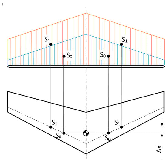
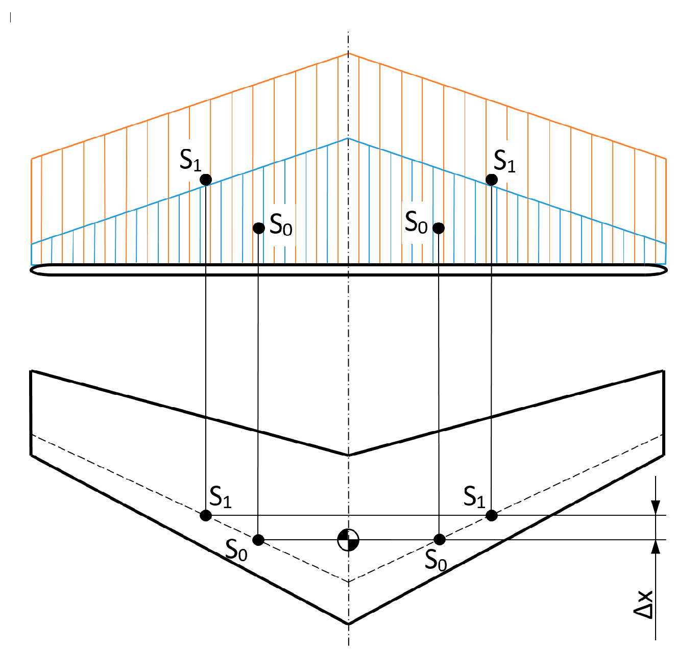
From the standpoint of longitudinal stability, the most favourable lift distribution along the wingspan is a triangular one (Figure 1). Assuming that the airfoil provides a constant centre of pressure located at 25% of the chord, equilibrium is achieved when the centre of gravity lies in the plane of symmetry of the aircraft on the line connecting points S, at which the resultant aerodynamic forces act on the right and left wings. For a triangular lift distribution, point S is located at one-third of the semi-span, as it corresponds to the centroid of a triangle. When the angle of attack increases, the lift force increases and the triangular distribution transforms into a trapezoidal one (curve 1 in Figure 1). The centroid of the trapezoid is located farther from the plane of symmetry than that of the triangle, meaning that the resultant lift force on each wing shifts toward the wingtip. Since the wing is swept, the lift force also shifts rearward. This results in the generation of a lift-induced moment about the centre of gravity that tends to pitch the aircraft nose-down, thereby restoring it to its previous attitude. When the angle of attack decreases, the opposite effect occurs. A similar, though less pronounced, behaviour is observed for lift distributions close to an elliptical shape.
Figure 1.
Influence of lift distribution on the stability of a flying wing model.
An elliptical lift distribution is considered the most aerodynamically efficient; however, experimental studies have shown that such a distribution alone is insufficient to ensure longitudinal stability. To simultaneously achieve an approximately elliptical lift distribution and a rearward shift in the center of pressure, the use of a self-stabilizing airfoil is recommended [29]. This group of airfoils is characterized by an uplifted trailing edge. These airfoils exhibit a reverse movement of the center of pressure. In classical airfoils, the center of pressure shifts towards the leading edge as the angle of attack increases. In contrast, for self-stabilizing airfoils, the center of pressure moves toward the trailing edge, which is advantageous for maintaining longitudinal stability, although it results in a reduced glide ratio [9].
Another factor influencing longitudinal stability is the wing sweep. While an increase in sweep can enhance stability, it simultaneously leads to a degradation of aerodynamic performance [28]. The stabilizing effect of sweep is beneficial only up to a certain limit. At higher sweep angles, although the lift force tends to shift further along the wing, the effective migration of the resultant lift force is relatively small, as the lift distribution extends over a greater distance from the plane of symmetry. The most favorable sweep angle is typically within the range of 15–20 deg [26].
2.2. Longitudinal Dynamic Stability
A restoring moment opposing a displacement does not, by itself, guarantee dynamic stability. The motion may continue with a progressively decreasing angular velocity or develop into oscillations of increasing amplitude about the equilibrium position. The primary factors contributing to improved dynamic stability are the mass distribution within the model and the static stability margin [30].
Mass distribution affects the damping of successive deviations during oscillatory motion. It is recommended that the mass of the model be concentrated as close as possible to the y-axis passing through the center of gravity [31,32]. For this reason, in conventional aircraft configurations, considerable emphasis is placed on minimizing the mass of the fuselage and tail, while the heaviest components are located at the center of gravity [31,32]. This is also why ballast in gliders is often placed within the wing. In the flying-wing configuration, this factor is of lesser importance, as the mass is inherently concentrated in the wing and the distance from the y-axis is typically small.
The static stability margin provides protection against aperiodic motion and is associated with shifting the center of gravity forward; however, this shift cannot exceed certain limits. The more forward the center of gravity is positioned, the stronger the tendency for the system to overshoot the equilibrium position [28]. While protection against aperiodic motion may induce oscillatory behavior, a compromise can be achieved by positioning the center of gravity 15–22% of the chord ahead of the neutral point [31,33].
2.3. Lateral Static Stability
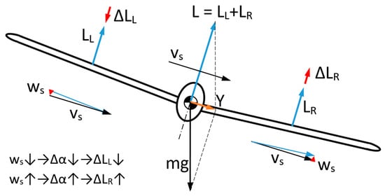
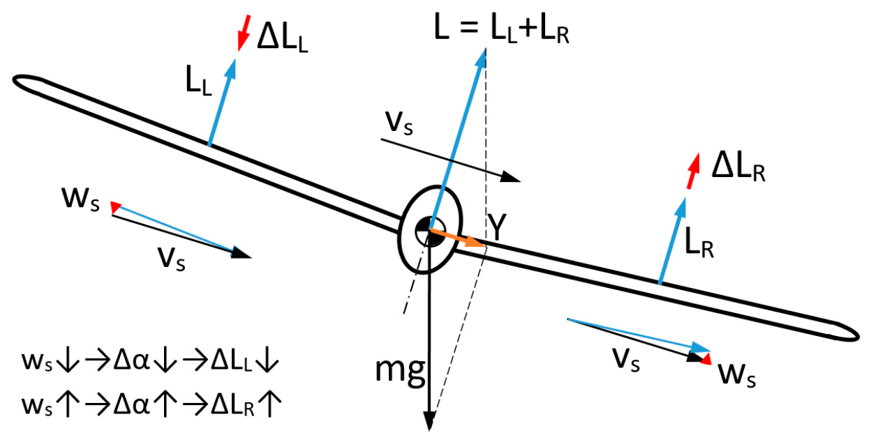
Lateral static stability of a flying wing refers to the aircraft’s ability to return to its equilibrium position after a rotation about the x-axis. A roll disturbance induces sideslip, defined as lateral motion relative to the original flight direction. This motion arises from the interaction between the lift distribution and the aircraft mass (Figure 2). In tailless configurations, lateral stability is achieved primarily through the wing design itself, including sweep, twist, and differential lift, rather than through a vertical stabilizer.
Figure 2.
Distribution of forces in left sideslip (front view).
Considering different wing velocities during sideslip for a wing with dihedral, it can be observed that the direction of airflow over the wings changes. In a left sideslip, the left wing experiences a downward vertical component of velocity, which increases its angle of attack and, consequently, its increasing lift. The opposite effect occurs on the right wing. These forces create a moment opposing the sideslip. Therefore, the greater the dihedral angle, the greater the stabilizing moment [34].
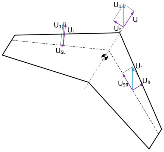
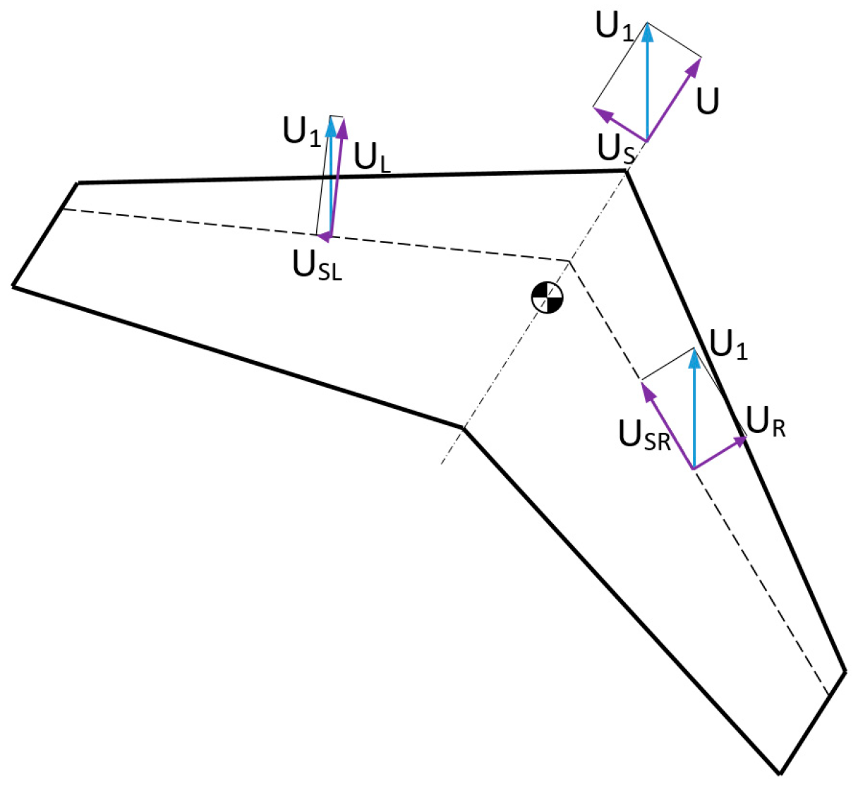
Wing sweep also affects lateral stability [35]. If the airflow around the swept wing is not aligned with the chord, it can be decomposed into longitudinal and perpendicular components, the latter of which does not contribute to lift. Considering a left sideslip with positive sweep, the left wing is exposed to a higher effective angle of attack; consequently, due to the reduced perpendicular component, a greater lift force is generated on that wing. This situation is depicted in Figure 3. In this case, a moment opposing the sideslip is generated. In summary, it can be stated that lateral stability is primarily influenced by the wing sweep and dihedral angles. Since the dihedral angle can be determined from the longitudinal stability condition, and a large portion of the stabilizing moment is generated due to dihedral. The angle of dihedral used in flying wing models should be 2–4 deg [26].
Figure 3.
Flow around a swept wing during sideslip.
2.4. Directional Static Stability
Directional static stability of a flying wing concerns the ability to return to equilibrium after a deviation about the z-axis. The primary factor influencing this behaviour is wing sweep. During sideslip, not only do the lift forces vary between the wings, but the drag forces also differ. In the left sideslip depicted in Figure 3, the left wing experiences a higher airflow velocity. Since both lift and drag are proportional to the square of the velocity, it can be inferred that the difference in drag forces between the wings generates a directional stabilizing moment [1,26]. Because in a conventional aircraft, directional stability is provided by the vertical stabilizer, the same will apply to optional vertical stabilizing surfaces on a flying wing.
2.5. Lateral Dynamic Stability
Lateral dynamic stability cannot be separated into roll and yaw components, as there is a strong coupling between the rolling and yawing motions of the aircraft. Analysis of static stability indicates that the onset of sideslip causes deviations from equilibrium in both the lateral and directional axes. Consequently, two moments are generated simultaneously: one that counteracts the aircraft’s roll and another that deflects the longitudinal axis of the aircraft toward the velocity vector. The relative magnitude of these moments determines the aircraft’s motion after being disturbed from equilibrium.
If the static directional stability is significantly greater than the static lateral stability, a spiral dynamic instability may occur. In such a case, before the insufficient lateral restoring moment can return the aircraft to a wings-level attitude, the dominant directional moment drives the aircraft from a sideslip into a progressively tightening spiral flight path [28].
Conversely, when static lateral stability predominates over directional stability, Dutch Roll instability may be observed. Here, the lateral restoring moment returns the aircraft to a horizontal position, but the weak directional moment is unable to eliminate the yaw deviation. As a result, the rolling motion induces a sideslip in the opposite direction, leading to a cyclic repetition of this coupled yaw–roll motion [28].
These two phenomena are mutually antagonistic: design measures that reduce spiral instability may promote Dutch Roll instability, and vice versa. For a conventional aircraft configuration with a tail, mitigating dynamic instabilities is relatively straightforward. An increase in wing dihedral improves lateral stability and thus counteracts spiral instability, while the vertical stabilizer provides directional stability, suppressing Dutch Roll instability. In the case of a flying wing configuration, however, it is not possible to directly identify individual design parameters that unambiguously improve dynamic stability, due to strong interdependencies between them. For example, increasing wing dihedral increases lateral stability, protecting against spiral instability, but at the same time, it increases directional stability, which magnifies spiral instability [25,35]. In order to protect the wing against spiral instability, the following measures may be taken:
- •
- the considered increase in dihedral will have a significant effect for wings with negative sweep, while for wings with positive sweep the effect will be small,
- •
- reduction in the model’s lateral areas (fuselage, vertical surfaces),
- •
- increase in the height of the vertical stabilizer (if considered),
- •
- increase in the fuselage area ahead of the center of gravity.
To eliminate Dutch Roll instability, one may:
- •
- reduce the wing dihedral,
- •
- increase the arm and area of the vertical stabilizer (if considered; by placing it at a considerable distance from the center of gravity).
Since the designed configuration is not intended to include auxiliary stabilizing surfaces, a wing with partially negative and partially positive sweep may be considered, and the required stability can be achieved by adjusting the dihedral of these sections.
3. Design and Analysis
3.1. Defining the Preliminary Geometry of a Flying Wing
To initiate the project, the following design assumptions were adopted:
- •
- an independently constructed unmanned aircraft with a maximum take-off mass (MTOM) of less than 25 kg, eligible for operation in subcategory A3 [36],
- •
- an aircraft configured as a flying wing with all equipment housed within the center section,
- •
- absence of stabilizing surfaces, including both horizontal and vertical stabilizers as well as winglets,
- •
- developing an aerodynamically stable aircraft based solely on its aerodynamic characteristics,
- •
- potential use of vortex generators and flow dividers to improve flight performance.
The detailed technical assumptions that needed to be defined prior to initiating detailed analyses of the airframe are presented below:
- •
- wingspan: 2 m,
- •
- take-off mass: 1 kg,
- •
- propulsion: Emax Grand Turbo GT2218/09 electric motor(Emax Yinyan Model Tech. Ltd., Shenzhen, China),
- •
- propeller: APC 10 × 4.7 (1290 g of thrust with GT2218/09 engine),
- •
- power supply: LI-PO 11.1 V 2300–1300 mAh (depending on the empty weight of the aircraft).
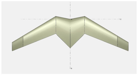
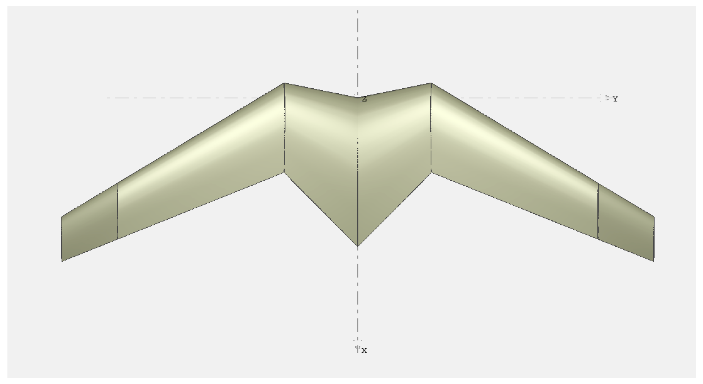
Based on the above considerations, it was decided to adopt a two-meter wingspan configuration with a clearly defined center section, as shown in Figure 4. The significantly thinner trapezoidal outer wings taper further toward the wingtips. A relatively large chord was applied in the center section to provide sufficient airfoil thickness for housing the onboard equipment.
Figure 4.
Preliminary geometry of flying wing.
The proposed solution offers several additional benefits. An airfoil with a larger chord generates higher lift, which results in a greater increase in lift on the center wing section as the angle of attack increases, thereby positively influencing the longitudinal stability of the aircraft. In addition, the use of negative swept enables a more rearward placement of the tractor engine, which may significantly contribute to achieving proper structural balance.
To ensure sufficient dynamic stability, positive dihedral was applied to the center wing section, whereas negative dihedral was implemented in the outer wing sections. Adjusting the angles of incidence in these sections affects the lateral and directional static stability of the aircraft.
Variable incidence was applied: initially higher for the center wing section, lower for the main wing, and negative at the wingtips. This configuration allows regulation of the effective angle of incidence. Downward-bent winglets were introduced to enhance directional stability, which is expected to be one of the main challenges in designing a flying-wing model without vertical stabilizing surfaces. The wing dihedral configuration is shown in Figure 5.
Figure 5.
Visualization of wing dihedral for preliminary geometry purposes.
The design and analysis were conducted using XFLR5 (v6.61) software, which is based on the Lifting Line Theory, Vortex Lattice Method (VLM), and 3D Panel Method for evaluating aerodynamic properties [37,38]. This tool enabled the analysis of the UAV’s stability characteristics and supported the iterative design process. Particular emphasis was placed on achieving an optimal balance between stability and overall UAV performance, especially with respect to lift and drag.
The design was subjected to preliminary flight tests to validate the computational predictions and to assess UAV performance under real-world conditions. The XFoil module integrated within XFLR5 was used to determine the aerodynamic characteristics of the airfoils required for calculating the aerodynamic properties of the system during construction optimization.
XFLR5 offers a relatively simple numerical approach commonly employed in the initial stages of aircraft design. It allows for the determination of force distribution on the analysed object, enabling verification of preliminary system calculations and assessment of the control characteristics of the simulated aircraft. It should be noted, however, that a significant mathematical limitation of this method is that the results are accurate only within the linear aerodynamic regime. In contrast to CFD (Computational Fluid Dynamics), VLM cannot reproduce complex viscous flows and does not incorporate wake modelling [38].
3.2. Analysis and Selection of Wing Airfoils
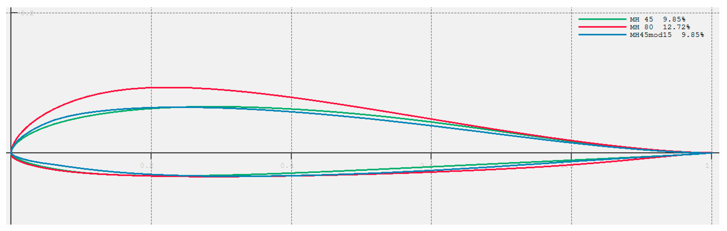
Summarizing the considerations from Section 2 regarding stability, several tendencies regarding the airfoil can be identified. To ensure stability, the force distribution on the wing must have a certain shape, preferably triangular, while for optimal wing efficiency, it should be elliptical. The wing must experience a positive moment and a backward migration of the aerodynamic resultant force with increasing angle of attack. A positive moment is provided by a self-stabilizing profile, but it also results in a lower Cl coefficient. Further migration is ensured by the dihedral, but it also reduces the total lift obtained on the wing. Additionally, the profile at the center section must have sufficient thickness to accommodate equipment. The requirements for this profile include adequate thickness and a high lift increment, certainly greater than that for the airfoil at the wingtip. Airfoil selection has been a key point in the present research. The main objective has been to design the aircraft with suitable cruise lift coefficient (around 0.2) at near zero angle of attack, with almost zero pitching moment around the center of gravity, while behaving with acceptable dynamic characteristics [39]. Initially, a speed range of an aircraft between 8 and 20 m/s was assumed. Since the speed and chord ranges were postulated for the analysis, the Reynolds numbers were conducted for the following ranges: 150,000–900,000 for the root and 50,000–400,000 for the tip. Additionally, disturbed flow over the center section was added (due to the presence of the engine). The results of the analysis narrowed down the choice to one of three airfoils: mh80, mh45, or the modified mh45 with the deflection arrow shifted to 20% chord, mh45mod20. Therefore, the mh80 airfoil was preliminarily selected for the center section of the wing, and mh45mod20 for the tip, further considerations were deferred to subsequent stages of the design process. Considered airfoils are presented in Figure 6, where red is mh80, green mh45 and blue mh45mod20. The MH family of airfoils is designed with a reflex at the trailing edge, which contributes to longitudinal stability in the absence of a tail.
Figure 6.
Selected airfoils.
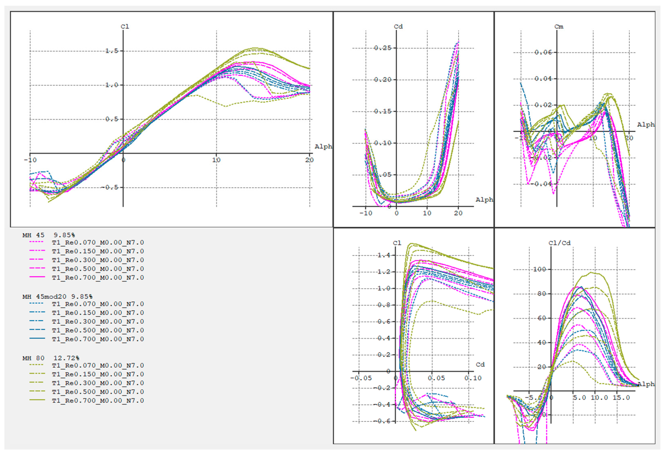
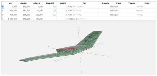
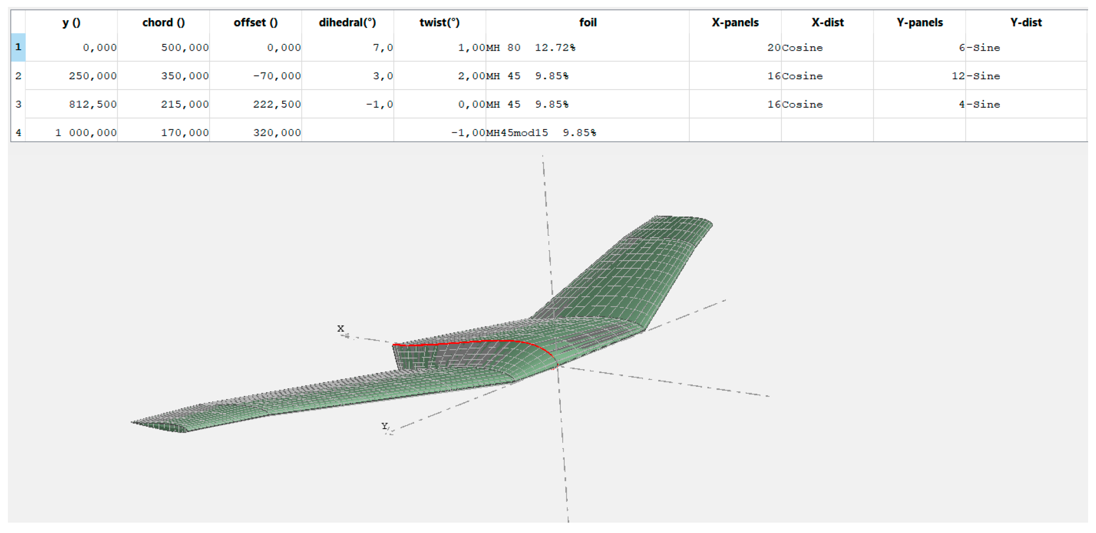
Analysis presented in Figure 7 are depicting the aerodynamic characteristics of selected airfoils for Re from 70,000 to 700,000. Mh80 stands out by its maximal lift coefficient and high critical angle for Re > 150,000. It has significantly higher drag coefficient for low Reynolds flow. It is also characterized by best glide ratio. The modification of the mh45’s deflection not only allowed for achieving a positive moment but also helped to smooth out the stall characteristic for low Reynolds flow. However, the negative consequence of the modification is a reduction in glide ratio, critical angle, and maximum lift coefficient. Both airfoils are much more suitable for low speeds and thin chord. The process commenced with inputting detailed geometry into the program, including the preliminary selected twist. The parameters are illustrated in Figure 7.
Figure 7.
Aerodynamic characteristics of selected airfoils (2D analysis).
3.3. Selection of Preliminary Geometry and Mass Distribution
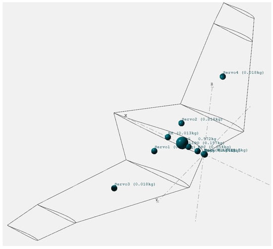
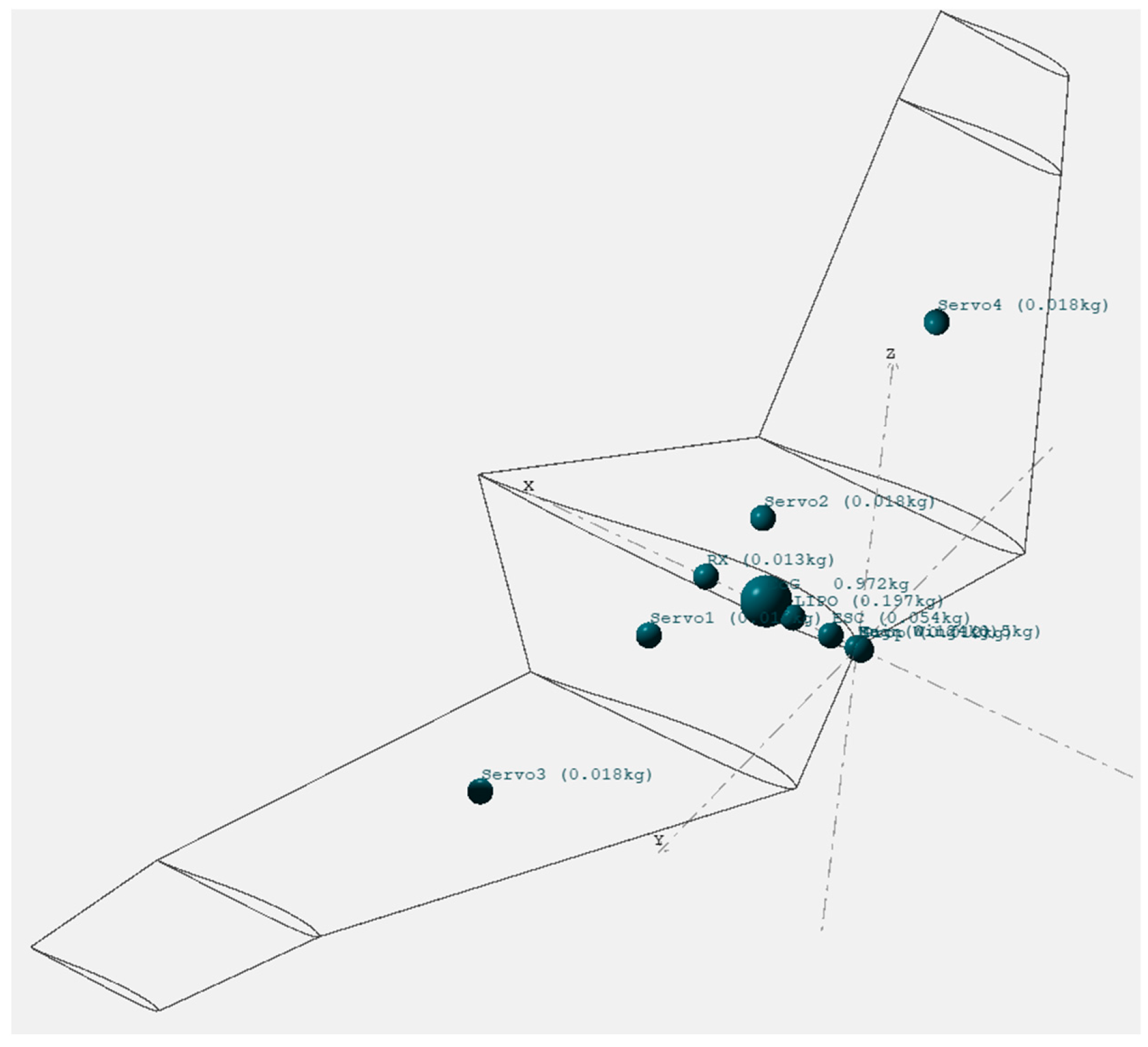
In the software, it is possible to define masses and check the center of gravity. The wing mass was estimated at 500 g, while the remaining components were weighed and entered into the program (472 g). This allows setting the internal masses of the wing in such a way that no additional ballasting is required. According to Gordon Whitehead’s formula, the center of gravity of a flying wing should be located at least at 1/6 of the Mean Aerodynamic Chord (MAC) [33]. Therefore, after graphical calculations, the CG (Center of Gravity) was determined to be 134 mm relative to the center of the coordinate system. The correct distribution of equipment is illustrated in Figure 8.
Figure 8.
Mass distribution in the wing.
The considered issue is of significant importance in designing a model of this size. It is a frequent practice to incorporate balance weights, which may exceed 20% of the total aircraft mass. Preliminary numerical analysis serves to mitigate such technical discrepancies.
3.4. Analysis of Aerodynamic Characteristics at Variable Angles of Attack
In the next step, an aerodynamic analysis of the aircraft was conducted. Initially, the lift distribution characteristic on the wing deviates from elliptical. Changes in wing twist were applied, and the chord of the wingtip was extended. To ensure a more elliptical lift distribution on the wing when changing angles of attack, the MH45 airfoil was used in the furthest part of the wing center.
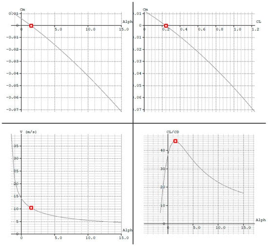
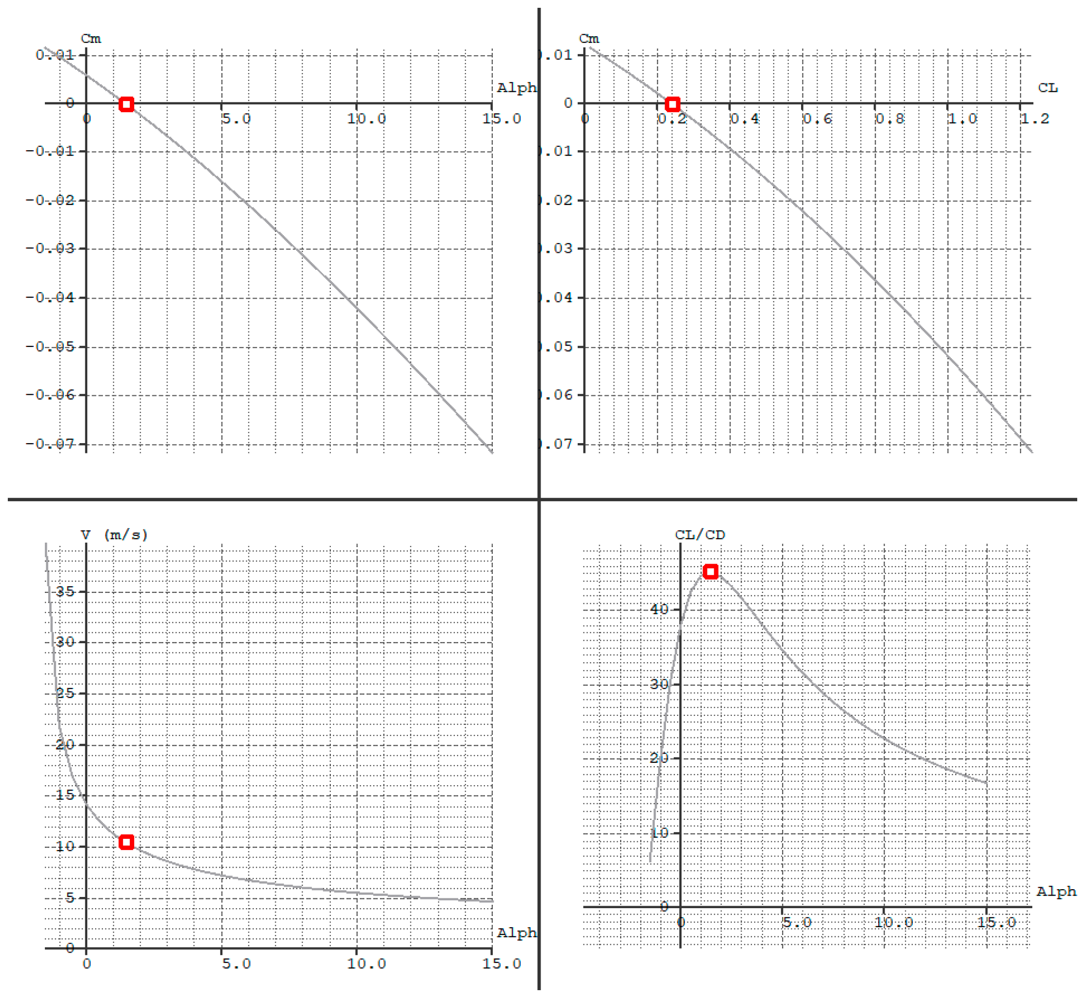
In the next stage, the aerodynamic characteristics were examined as a function of angle of attack. Further geometry adjustments were applied to stabilize the aircraft at a higher positive angle of attack, ensuring maximum efficiency. Several attempts were made, but the best results, as shown in Figure 9, were achieved with the geometry presented in Figure 10.
Figure 9.
Aircraft aerodynamic characteristics corresponding to geometry in Figure 10.
Figure 10.
The aircraft geometry ensuring longitudinal stability at the angle of maximum efficiency (corresponding to the characteristics in Figure 9).
3.5. Analysis of Lift Distribution Along the Wingspan
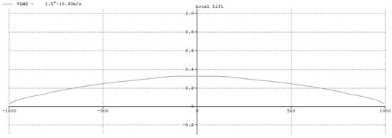
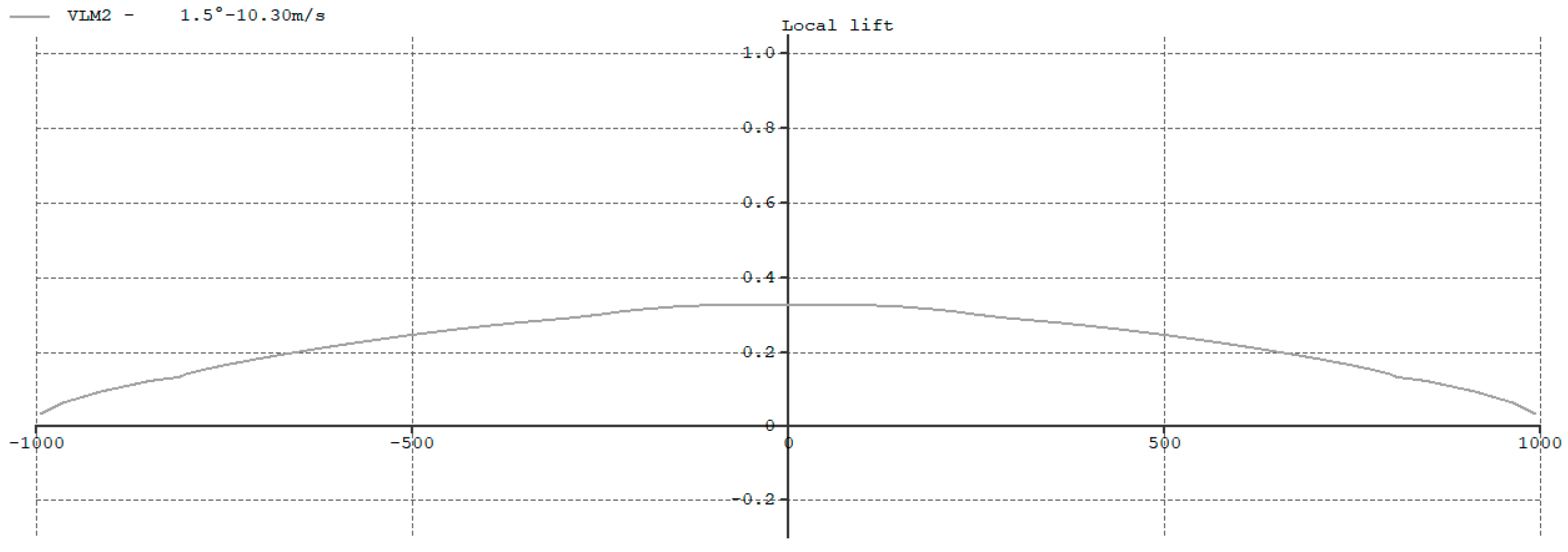
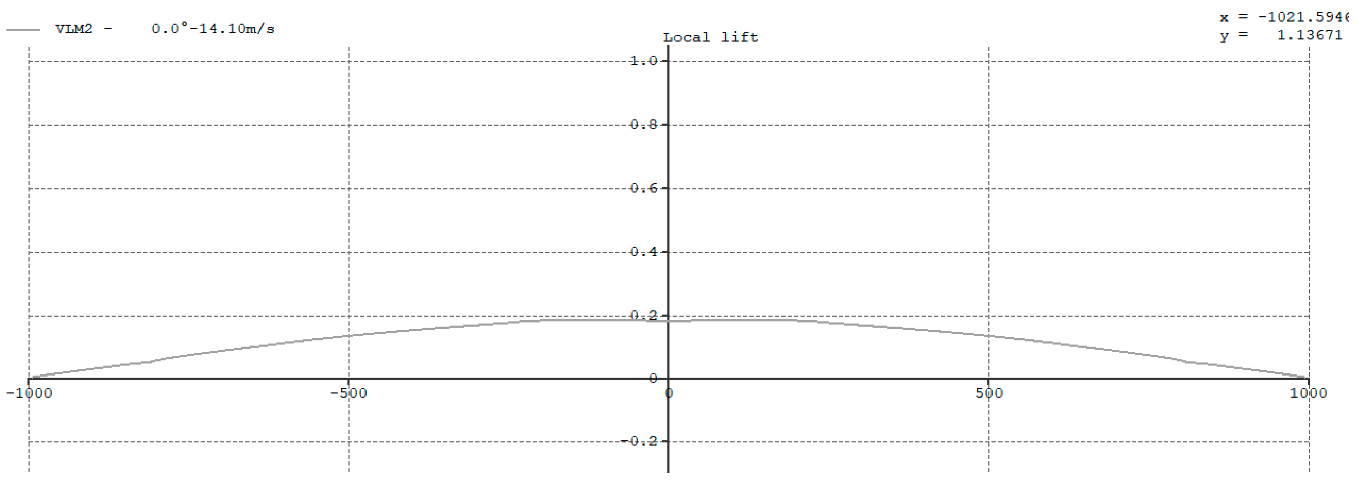
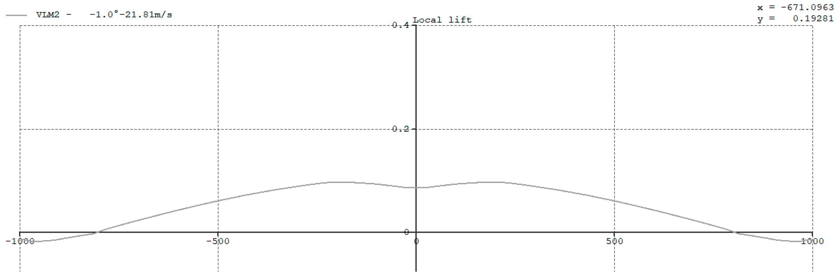
Figure 11, Figure 12 and Figure 13 show the lift distributions along the wing for three different angles of attack. Figure 11 presents a distribution close to elliptical (and thus the most aerodynamically favorable) at an angle of attack of 1.5 deg, which provides the highest aerodynamic efficiency. At this angle, the aircraft is calculated to achieve a cruising speed of 10.3 m/s.
Figure 11.
Lift distribution for an angle of attack of 1.5 deg.
Figure 12.
Lift distribution along the wingspan for an angle of attack of 0 deg.
Figure 13.
Distribution of the lift coefficient along the wingspan at a negative angle of attack (−1 deg).
At an angle of attack of 0 deg, the lift decreases, and the calculated cruising speed is 14.10 m/s. This angle of attack can be considered optimal for faster cruising.
At a negative angle of attack, negative lift is observed at the wingtips, which significantly enhances wing stability, but at the cost of increasing total drag by approximately 180% [26]. This results in beneficial stabilization for the considered model at high speeds, as well as the potential for energy dissipation during diving and landing approaches. In summary, this subsection demonstrates that satisfactory aerodynamic characteristics of the aircraft were achieved.
3.6. Stability Analysis
The following step in the analysis focuses on evaluating stability. The XFLR5 software includes a stability analysis module equipped with visualization of the aircraft’s behavior under external influences. In the analysis, two functions of the program were used: the aforementioned visualization and a tool for drawing damping curves. The software allows for the examination of responses to several different modes of excitation, enabling the investigation of short-period mode, phugoid (long period) mode, and lateral stability including Dutch Roll.
3.6.1. Short-Period Oscillations and Phugoid Mode
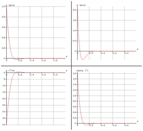
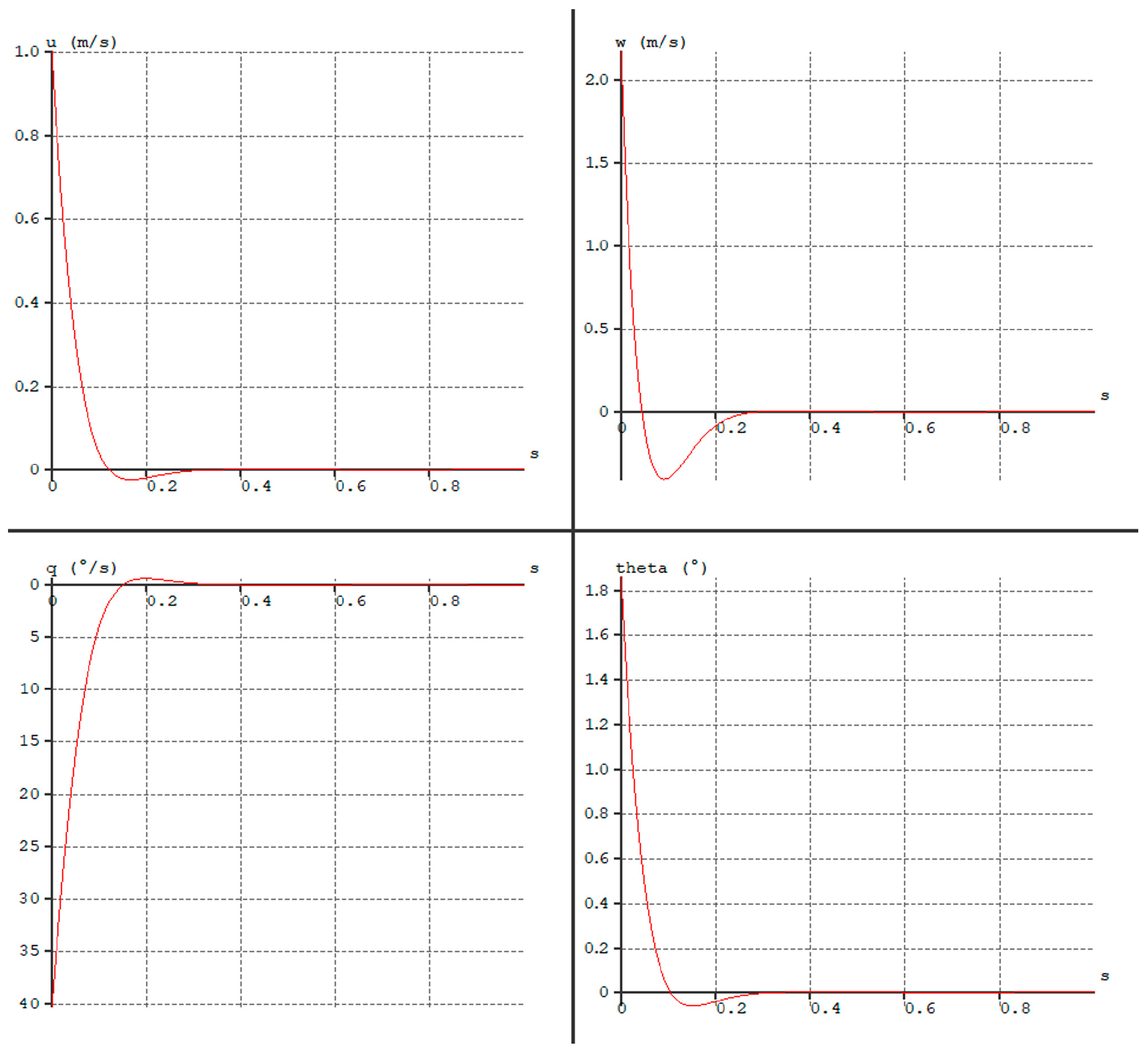
Short period pitch damping due to disturbance from longitudinal equilibrium are presented in Figure 14. Starting from the top left corner and proceeding clockwise, the graphs depict longitudinal velocity, vertical velocity, pitch rate, and pitch angle over time. From the graphs, we can observe that the aircraft stabilizes after approximately 0.3 s with a small overshoot after 0.1 s, which does not significantly affect the flight. The short-period oscillation frequency, estimated from stability derivatives, is 1.63 Hz (oscillation period 0.6 s) with a damping ratio of 0.82.
Figure 14.
Analysis of short-period oscillations in the longitudinal motion.
The phugoid mode parameters determined by XFLR5 are a frequency of 0.16 Hz (oscillation period 6.25 s) and a damping ratio of 0.01.
3.6.2. Roll Subsidence Mode
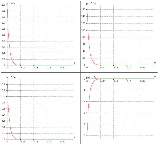
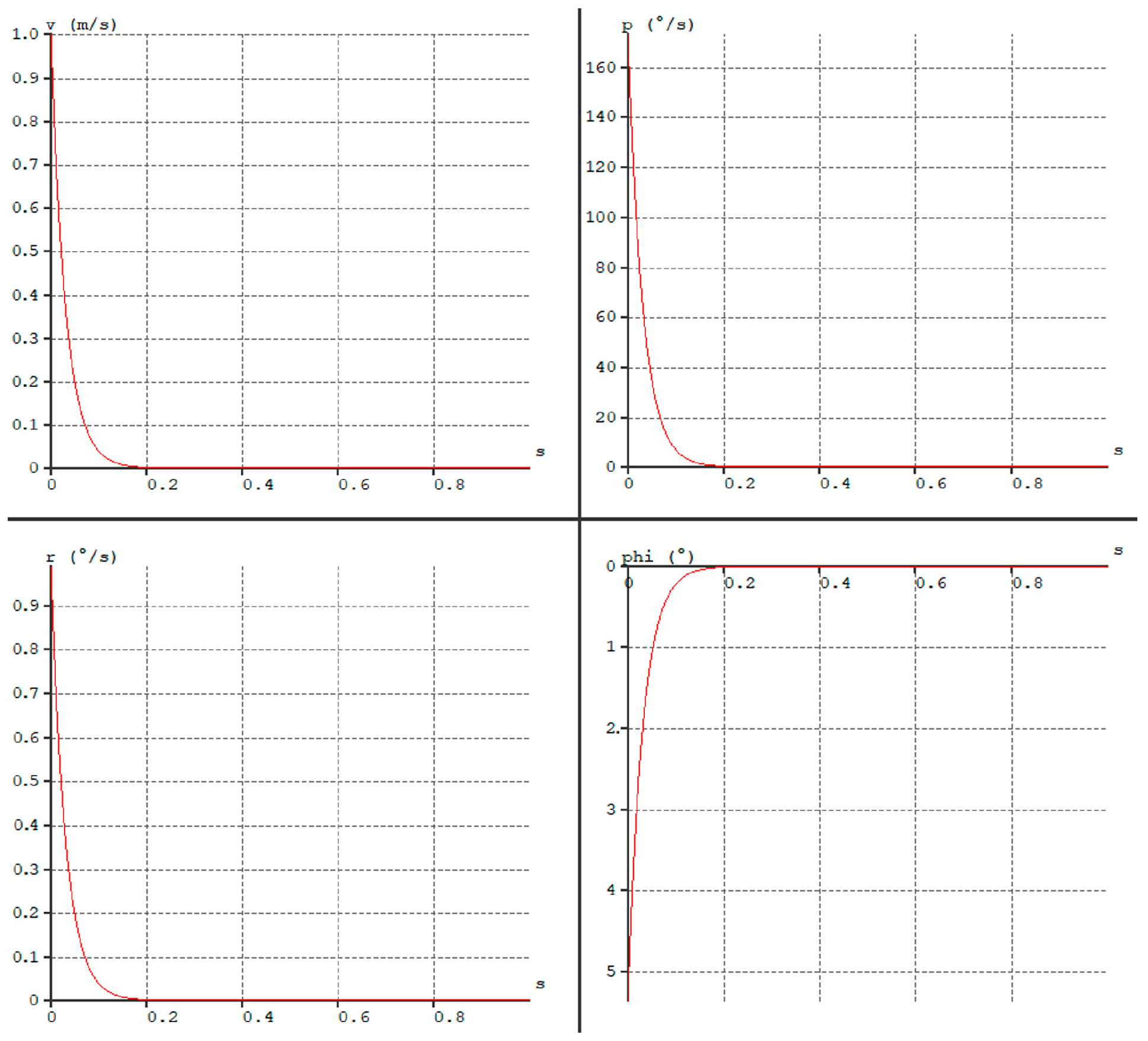
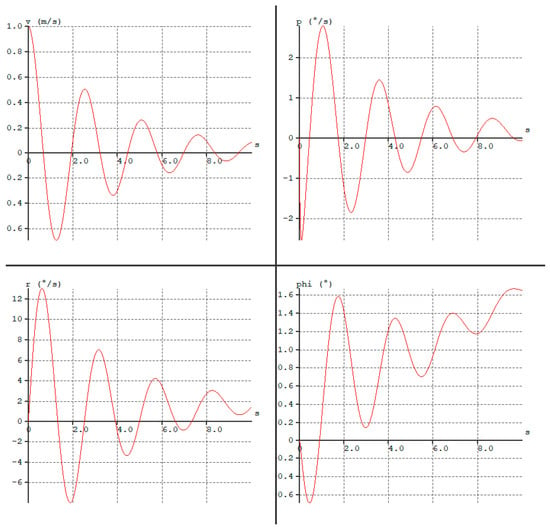
In Figure 15, an analysis of aperiodic roll damping is presented. The graphs show lateral velocity, roll rate, yaw rate, and roll angle over time. The aircraft stabilizes after 0.2 s, and the shape of the graphs is more appropriate than in the previous case because the aircraft does not pass through the equilibrium position.
Figure 15.
Analysis of aperiodic roll damping.
3.6.3. Dutch Roll Mode
In the next step, lateral stability was examined, which denotes a Dutch Roll motion induced by lateral airflow. The excitation in this analysis involves yawing the wing into flight straight traversal. In the initially considered configuration, the model entered lightly damped oscillations. Initially, it rolled toward the opposite wing relative to the disturbance, and then rolled back toward it. This was an almost textbook example of Dutch Roll instability [40].
To improve the aircraft’s characteristics, the goal was to increase directional stability while simultaneously reducing lateral stability by an amount that would not induce wing oscillations. Additionally, the optimized parameters from previous considerations were to be maintained. Operations on dihedral and twist were performed. Furthermore, it was decided to change the wingtip airfoil to Mh45 because the aircraft had a satisfactory longitudinal stability margin, and the original airfoil had a higher critical angle of attack. The change, coupled with appropriate wing twist adjustments, allowed for a similar lift distribution on the wing as depicted in Figure 13. Further increasing the dihedral of any of the three wing segments worsened the aircraft’s stability, leading to a decision to reduce dihedral. While minimizing dihedral helped reduce the amplitude of Dutch Roll oscillations, it led to an increase in wing roll amplitude.
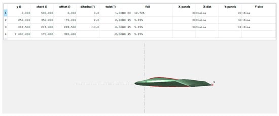
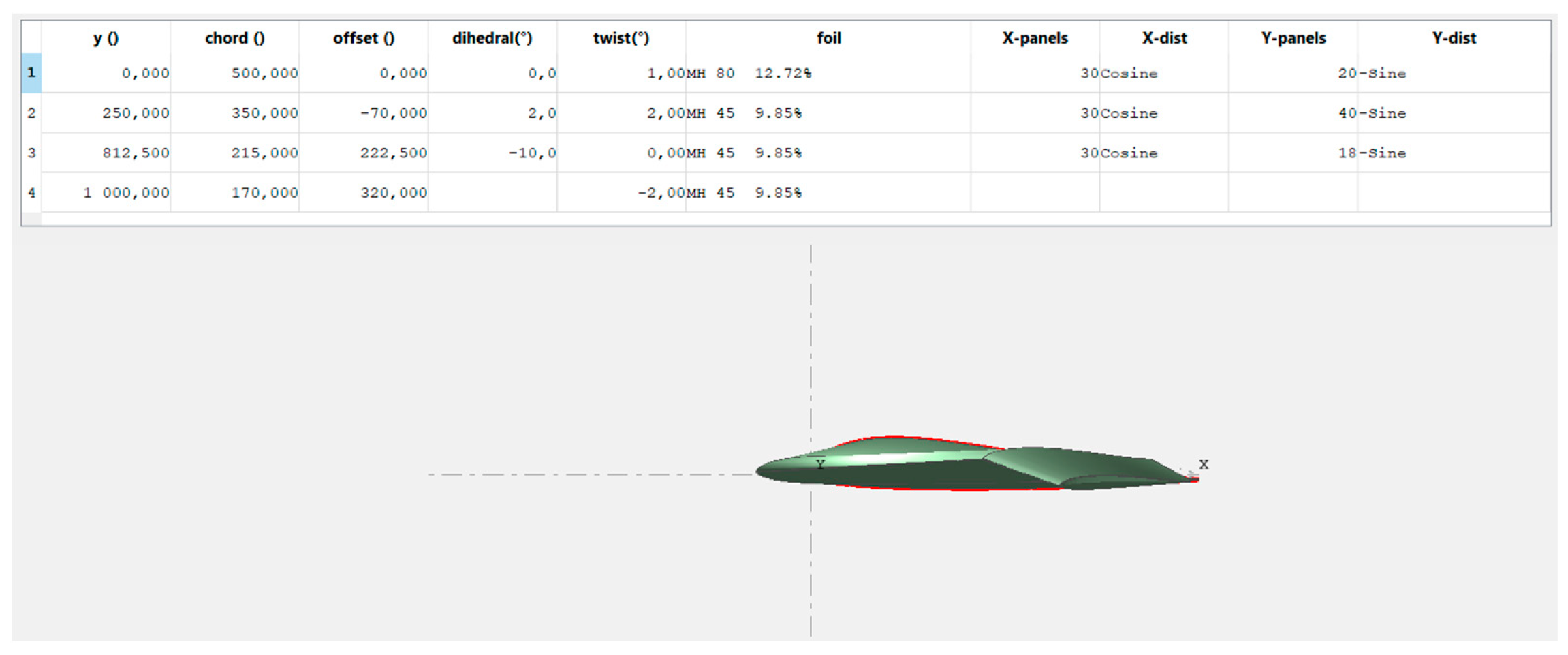
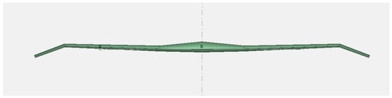
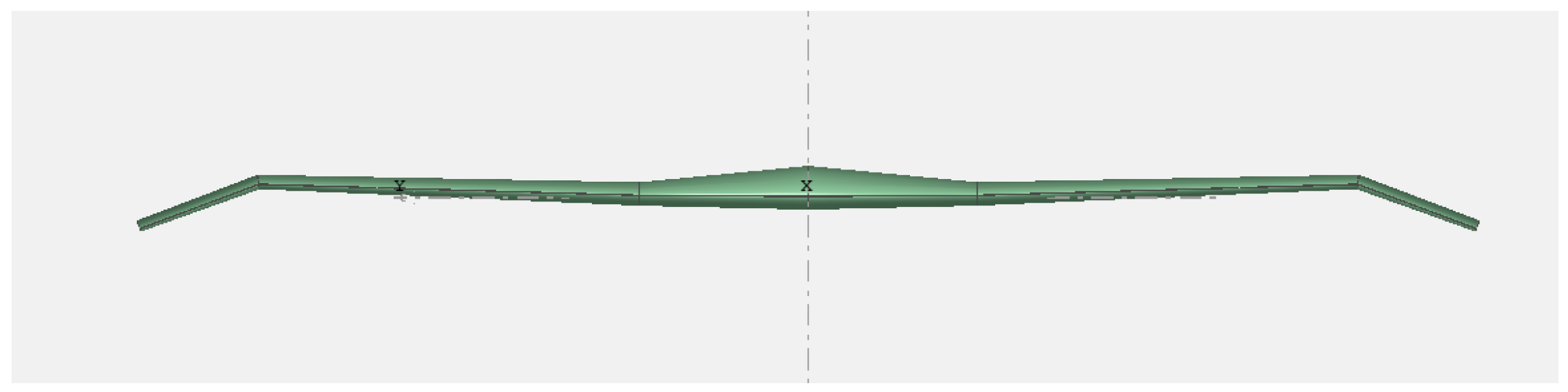
To achieve satisfactory model behavior, actions on the equivalent dihedral were necessary. The best parameters were obtained by applying slight positive dihedral along the wing and significant negative dihedral at the wingtips. This solution provided satisfactory lateral stability along the entire wing, excluding the wingtips where negative dihedral and additional negative twist increased drag, significantly reducing lateral stability but enhancing directional stability. The final aircraft geometry is depicted in Figure 16 and Figure 17.
Figure 16.
Final geometry side view.
Figure 17.
Final geometry front view.
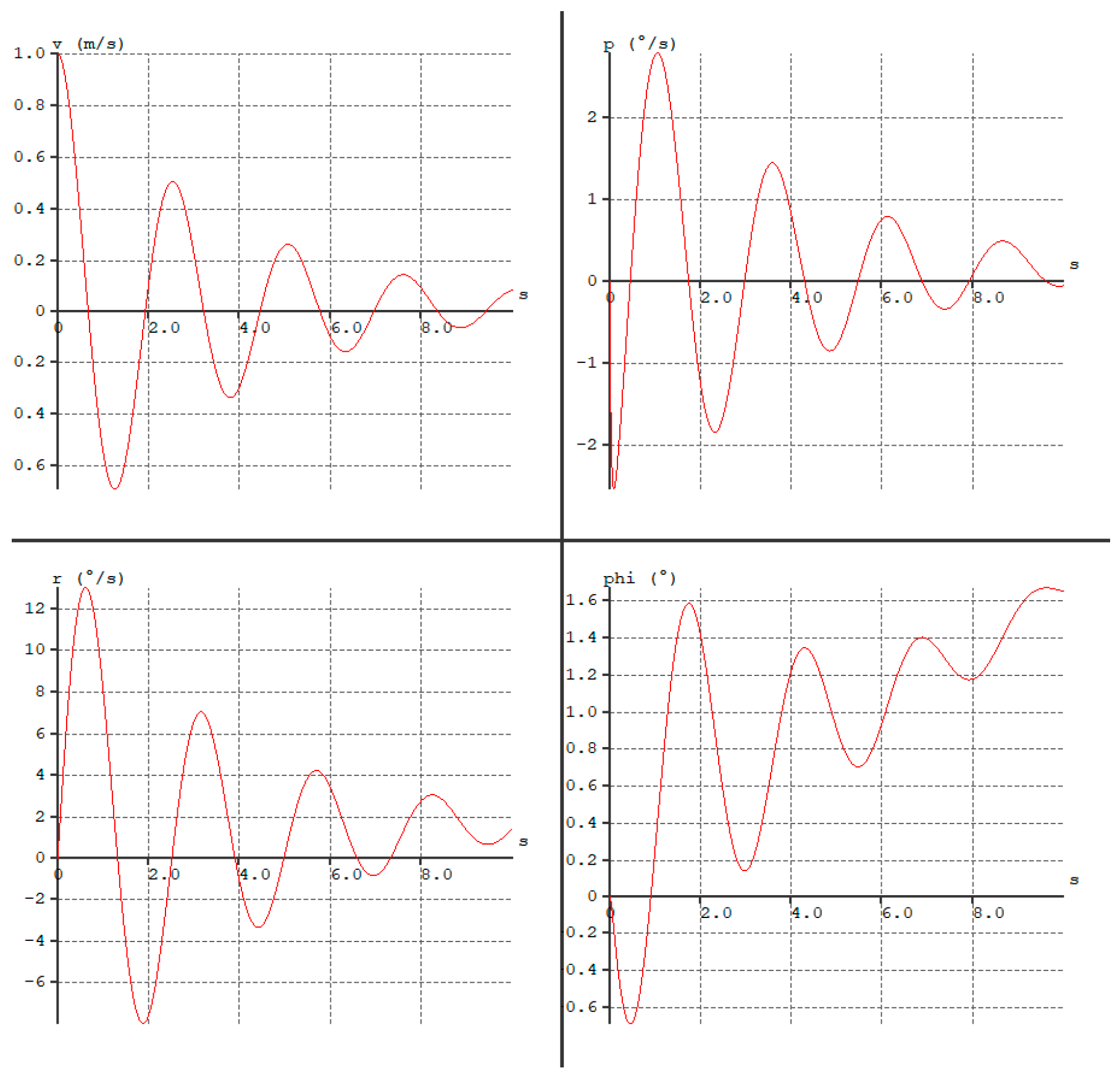
The Dutch-roll frequency, estimated from stability derivatives, is 0.39 Hz (oscillation period 2.56 s) with a damping ratio of 0.11. The analysis of lateral stability is presented in the graphs in Figure 18. We can observe a slight roll rate of 2 degrees per second and a significant yaw rate of 13 degrees per second, which decreases by 40% after the first passage through the equilibrium position. Although this behavior is not ideal, it is considered close to optimal and does not deteriorate the aerodynamic characteristics.
Figure 18.
The damping of Dutch Roll after final modifications.
4. Prototype Structure and Initial Flight Tests
4.1. Design and Equipment of the Flying Wing
The influence of geometry on flow disturbance was also analyzed. Airflow disruptions over upper wing surface that depict upcoming tip stall were observed. It was deemed acceptable given the achieved stability. The considered vortex significantly increased for a higher absolute value of the incidence angle than the applied negative 20 deg. The use of a more aggressive incidence angle poses another problem. Further bending of the wingtips downward makes them more susceptible to damage during landing. At this stage, it was decided to conclude further simulations and proceed with the construction of the prototype.
The process began with printing and cutting out the wing airfoils out of plywood, followed by the construction of a custom-made foam cutting frame that consists of a resistance wire with a diameter of 0.4 mm connected to a transformer, along with tensioning rubber bands.
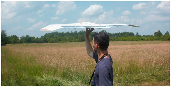
After cutting, the foam blocks were reinforced with spars joined together with fiberglass at the connection points. In the center section of the wing, a 3 mm plywood motor mount rib was inserted along the center wing to serve as a spar. For the rest of the wing, pine strips measuring 10 mm × 3 mm were used. A hatch was cut out for electronics based on the weight distribution diagram shown in Figure 8. The entire structure was then covered with Japanese paper, resulting in a rigid construction with a slightly rough surface, which is advantageous for airflow characterized by low Reynolds numbers [33]. After covering and allowing the glue to partially dry, the wing was closed for two days to prevent any changes in wing twist caused by the glue. This was crucial because even a 1-degree change in twist during individual analyses significantly affected the characteristics [41]. The next step involved cutting out the control surfaces, reinforcing them with aluminum tape for hinges and structural support. Then, the electronics were installed. Two servos controlling the center flaps of the center section were placed under the hatch, while two others controlling the main wing flaps were mounted under the wing. It was decided to use four deflectable flaps, with two acting as elevators and two functioning as ailerons. For directional control, a “drag rudder” system was implemented [42]. To achieve a right yaw, the right aileron deflects upwards at a small angle, while the elevator flap deflects downwards at a much larger angle. This significantly increases drag by expanding the vertical surface area while maintaining the necessary lift for level flight. A similar solution was employed in the B2 aircraft [17]. The surfaces were selected to be 20% of the wing chord. Maximum control surfaces deflection of 30 deg was established for first flight test. Additionally, a small skid was glued under the center section, serving as a handle for hand launching. The motor was mounted on spacers made from a 8 mm diameter aluminum tube. Ready to fly aircraft was presented in Figure 19.
Figure 19.
Prototype in take-off configuration.
4.2. Maiden Flight and Initial Tests
The maiden flight took place on a warm day in a meadow covered with tall grass. In the event of a failure, the grassy surface was intended to mitigate the impact force, thereby facilitating rapid structural modifications and a subsequent retest. Additionally, a special elevons mix was prepared for all four control surfaces, activated by a designated switch on the transmitter. When activated, all surfaces functioned as elevators, with the center ones deflecting approximately 10 degrees more. Similarly, they all acted as ailerons, with the center ones deflecting 10 degrees less. The aim of this modification was to increase the control authority of the model if it turned out insufficiently steerable. These settings were used for the maiden flight. The model required minor trimming. It proved longitudinally and laterally stable, as calculated. However, there was a moderate wind during the flight, around 4 m/s. When flying crosswind, there was a slight Dutch Roll, which could pose a challenge for an inexperienced pilot. By applying slight control inputs at the right moment, the Dutch Roll could be minimized to almost imperceptible levels. Moreover, in case of no response after the fourth oscillation, approximately after 8 s, the system stabilized in straight flight.
After turning off the engine and releasing the controls, the aircraft stabilized at a positive angle of attack in accordance with the simulations conducted. Comparing gliding and powered flight (pilot’s assessment), a significantly smaller negative influence of the engine moment can be observed compared to similar designs equipped with vertical stabilizers.
In the second flight, the center of gravity was shifted forward by 15 mm to reduce the aircraft’s sensitivity to control inputs. The atmospheric conditions remained similar, and in this case, too, the stability analysis performed in the XFLR5 program was confirmed by pilot’s direct qualitative assessment. During crosswind flight, the model entered into increasing oscillations. It was decided to return to the previous position of the center of gravity.
In the next flight, it was decided to check how the aircraft behaves during larger bank angles. Several 60 and 90-degree turns were made. No flight path instabilities were observed; the aircraft did not yaw up or down during the turn. It was decided to climb higher and perform a dynamic stall. The aircraft stalled, and without pilot intervention, it stabilized at a positive angle of attack, losing about 5 m in height in the process. The behavior was entirely correct. A stall in level flight had a similar effect, but the loss of altitude was reduced.
Several attempts were made to induce the model into a temporary loss of controllability when entering a spin. It is noteworthy that the system exhibits no inherent tendency toward this critical maneuver, ensuring operational safety. However, it was finally achieved by deflecting the elevons at the appropriate moment during a straight and level flight at idle power. After completing one full roll and releasing the controls, the aircraft immediately stopped rotating and transitioned into a slowly flattening dive. This phenomenon is also desirable.
In subsequent trials, experimentation was conducted with aerobatic maneuvers. The only technical limitation arises from the inverted flight, in which maintaining course proves to be very difficult, attributed to the reversed wing dihedral, which deteriorates lateral stability.
After conducting the tests, it was decided to assess the piloting characteristics of the constructed object. For this purpose, the Cooper-Harper scale was used [28,43,44,45,46]. This scheme was introduced to facilitate communication between experimental pilots and designers. It consists of a 10-point scale, with the assessment recorded in parentheses and elaborated upon [28]. The evaluated system can be rated as 3 on the Cooper-Harper scale, indicating that modifications to the aircraft are not necessary. However, in the case of crosswind flight, compensatory action is required to quickly recover the aircraft from slight Dutch Roll. The configuration with the forward-shifted center of gravity can be rated as 4, considering the tendency to enter oscillatory motion in the yaw channel. Remedial action required—revert to the previous configuration.
5. Construction of the Final Structure and Flight Tests
5.1. Aircraft Structural Modifications
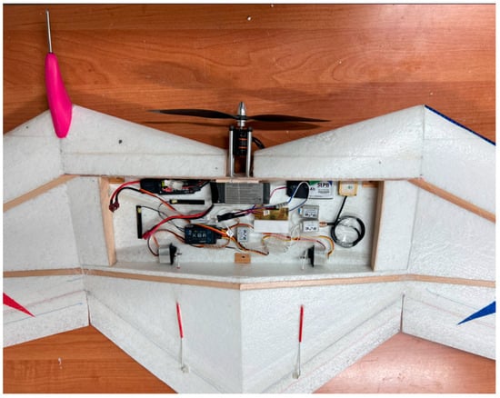
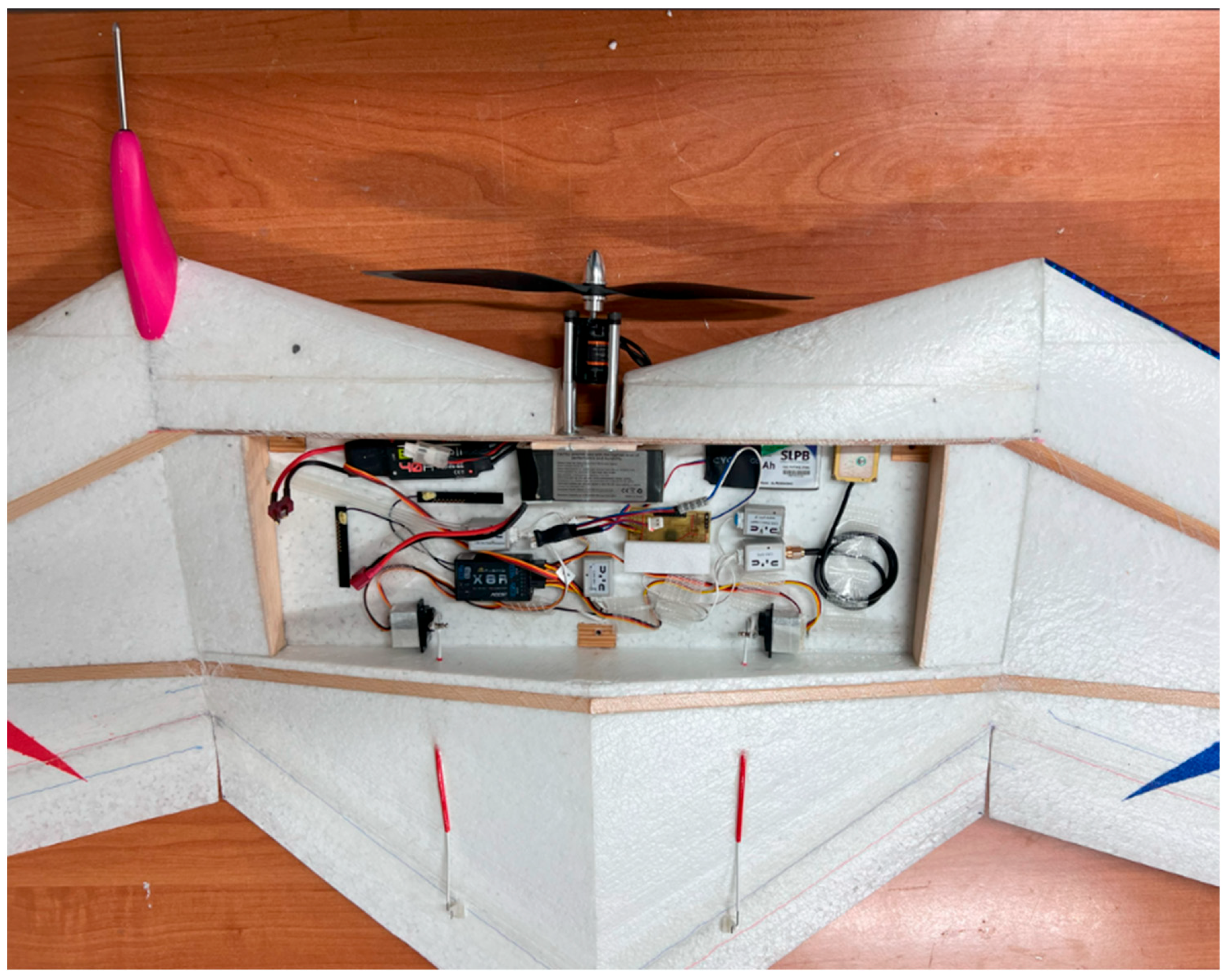
Flight parameter recording on the prototype showed that the IMU system is highly sensitive to vibrations transmitted from the propulsion unit. To compensate for these vibrations, the use of an anti-vibration mount was considered. After taking into account experience from previous projects and designs, it was decided to laminate the equipment bay, enlarge it, and increase the spacing between components (Figure 20). In addition, attention was paid to locating the IMU at the aircraft’s centre of gravity (in a 3D sense). It was also decided to increase the structural stiffness by introducing an additional spar cap across the centre wing section and by covering the aircraft with fiberglass. Furthermore, a decision was made to at least partially paint the structure to improve visibility in flight. Vibration reduction from the engine was ensured by using a factory-new engine (the one used in the prototype had previously been operated in other projects), machining a new hub with a tight fit to the propeller, and precisely balancing the propeller.
Figure 20.
A distributed recording system installed on board the aircraft.
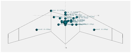
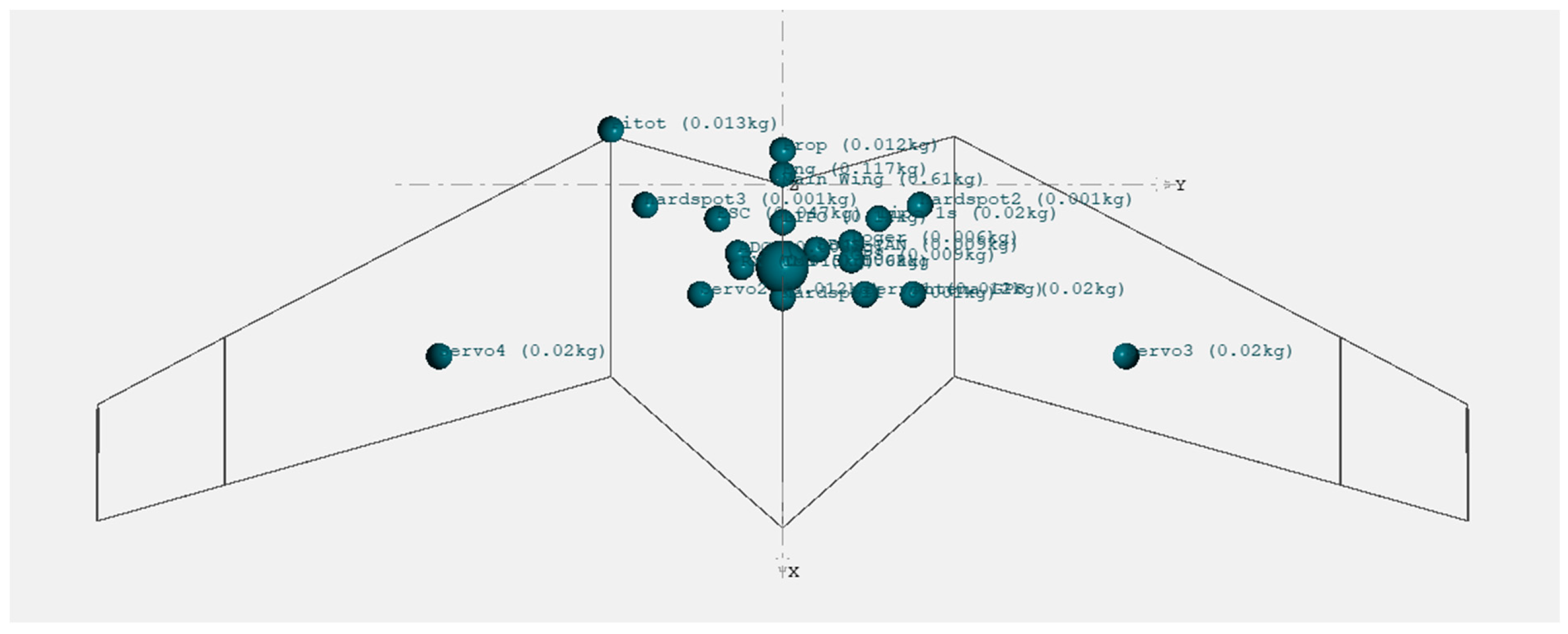
In the correct arrangement of the aircraft equipment, including the configuration of the PRP-W2 flight parameter recording system [47,48], mass analysis played a crucial role. By defining mass concentration points, it was possible to accurately plan the placement of the equipment in order to achieve the previously calculated center of gravity along the longitudinal axis, while simultaneously maintaining a neutral center of gravity position along the lateral axis. Wherever feasible, equipment components were concentrated near the longitudinal axis of the model, which is essential for ensuring the lateral stability of the aircraft in the analyzed configuration. The mass of the aircraft without onboard equipment was 610 g, while the equipment itself accounted for nearly half of the takeoff mass. The mass analysis is illustrated in Figure 21.
Figure 21.
Graphical presentation of the aircraft mass distribution in the final solution.
5.2. Flight Tests
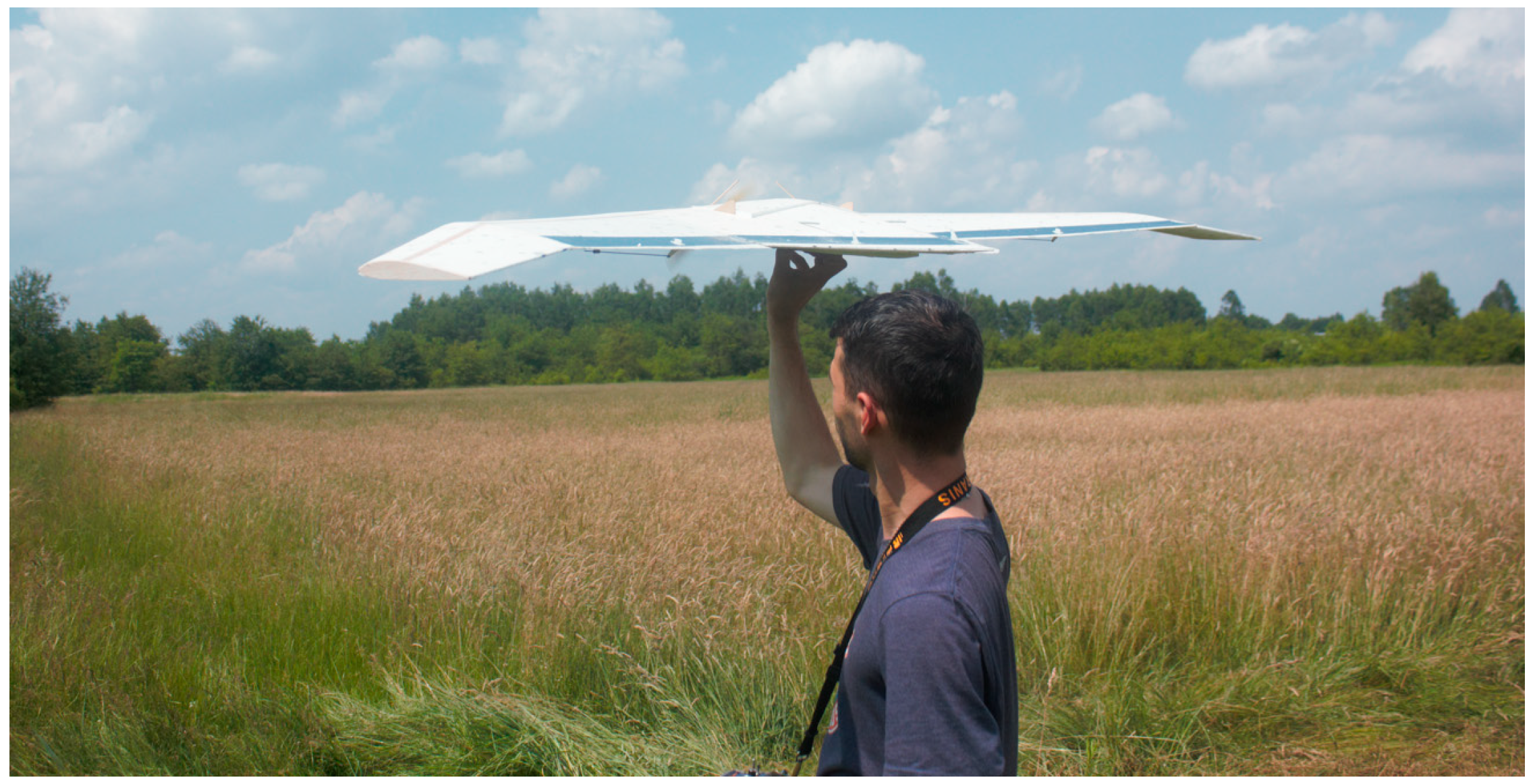
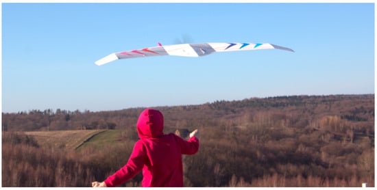
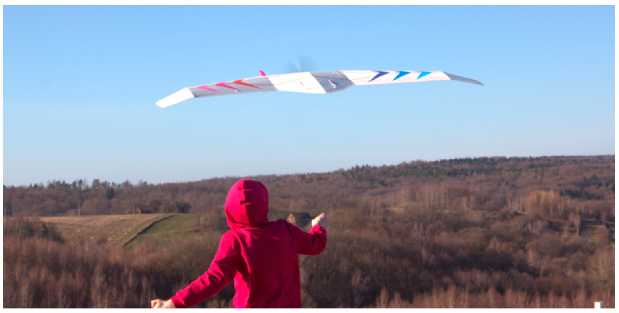
Flight parameter data were recorded during six test flights (Table 1). Since the last four flights were conducted under calm, windless conditions, it was decided to use data from flights No. 3, 5, and 6 for further analysis. Synchronization of the flight recorded from the ground (video footage) with the flight parameters obtained from the onboard data recorder proved to be very valuable during the analysis. The aircraft in flight is depicted in Figure 22.
Table 1.
Summary of flights.
Figure 22.
Final flying wing configuration during takeoff.
6. Analysis of the Obtained Results and Discussion
6.1. Dutch Roll
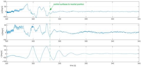
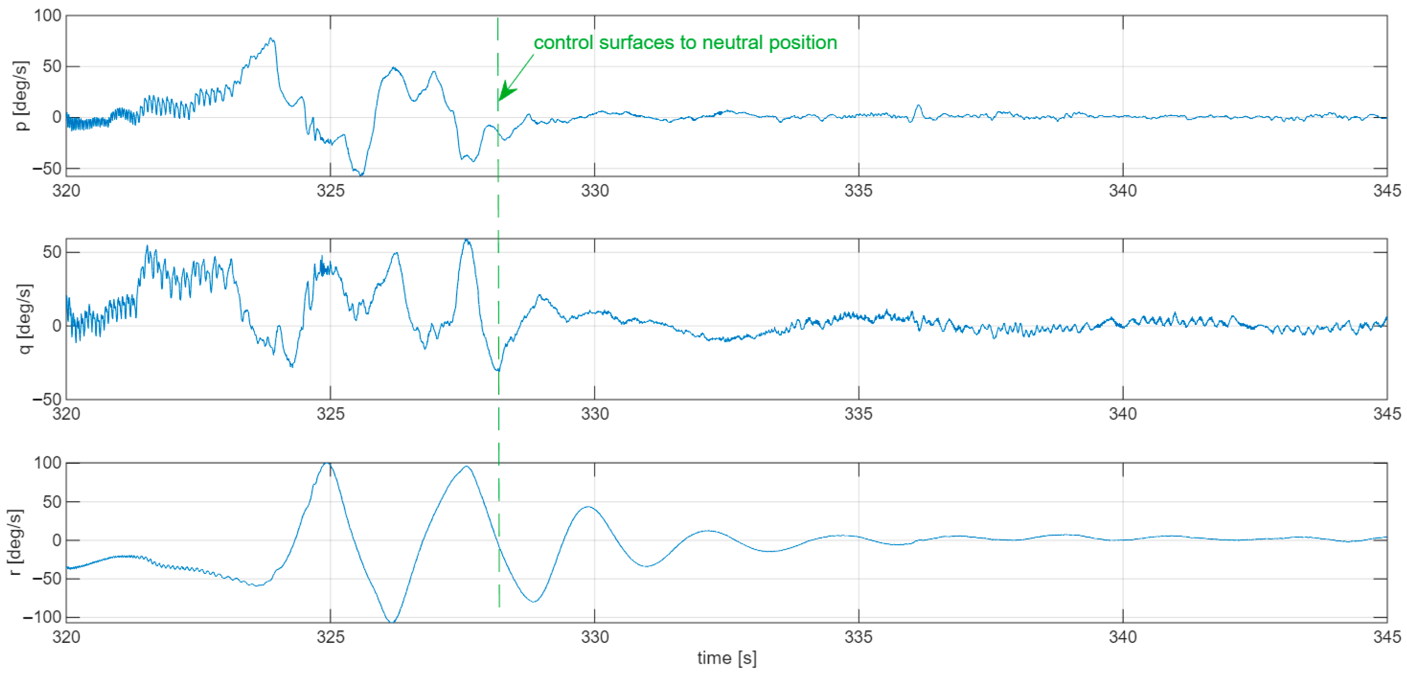
During flights 1–4, intermittent Dutch Roll oscillations could be observed. Figure 23 illustrates the onset of Dutch Roll at 324 s of flight time (green dashed line indicates the moment when the pilot released the controls), after which the flight stabilized with damped oscillations having a period of 2.5 s and a reduction in amplitude by half already after the first cycle. These oscillations did not decay completely even after a longer period of time; however, their amplitude became sufficiently small to remain unnoticeable to the pilot. The use of the data recorder made it possible to detect this undesirable phenomenon. In the analyzed data segment, slight variations in pitch angular velocity can also be observed, indicating adequate longitudinal stability (quick damping of oscillations in the pitch channel—zeroing of the angular velocity q, clearly visible in Figure 23) and insufficient lateral (directional) stability of the aircraft during flight without installed turbulators (slowly decaying oscillations in the yaw channel, observable as changes in the angular velocity r in Figure 23).
Figure 23.
Dutch Roll oscillations in Flight nb 3.
6.2. Responses to Impulse Excitations
At the beginning of this section, the control surface deflection mixer used since the first flight of the prototype is discussed. The wing features four aerodynamic control surfaces: two located on the center section (hereinafter referred to as elevons) and two distributed along the wing (hereinafter referred to as ailerons). In practice, all of these surfaces perform the combined functions of elevons, ailerons, and the rudder. Pulling the control stick toward the pilot results in an upward deflection of all four surfaces (in appropriate proportions). An analogous response occurs when the stick is pushed forward. Deflecting the stick to the right causes a proportional upward deflection of the right-hand surfaces and a downward deflection of the left-hand surfaces, with the opposite effect occurring for left deflection. Yaw control is achieved by increasing drag on the wing half corresponding to the direction of stick deflection. This is implemented by simultaneously deflecting the aileron upward and the center-section flap downward. This results in the bell-shaped lift distribution discussed in the theoretical analysis, significantly increasing drag. At the same time, the increase in lift on the center section compensates for the decrease in lift on the outer wing.
6.2.1. Longitudinal Motion
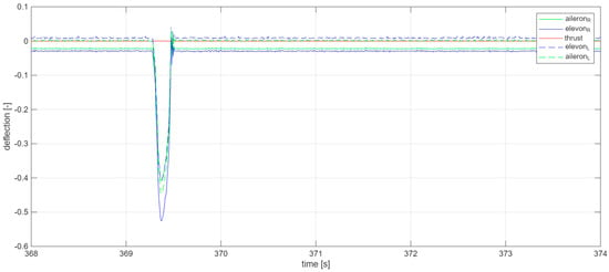
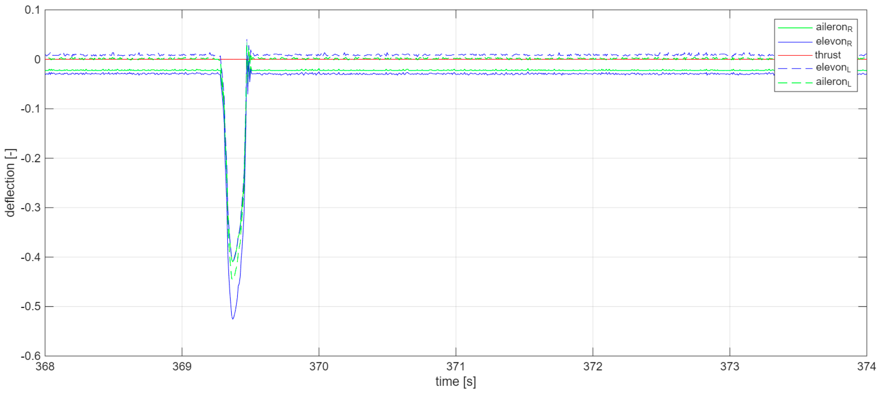
For the analysis, a segment of free flight with a quasi-impulse deflection of the aerodynamic control surfaces responsible for changes in the pitch angle was selected. Figure 24 shows the deflections of the control surfaces (ailerons and elevons) over the time interval corresponding to the considered scenario.
Figure 24.
Quasi-impulse excitation in longitudinal motion in Flight nb 3.
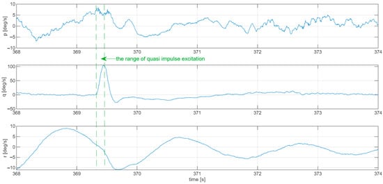
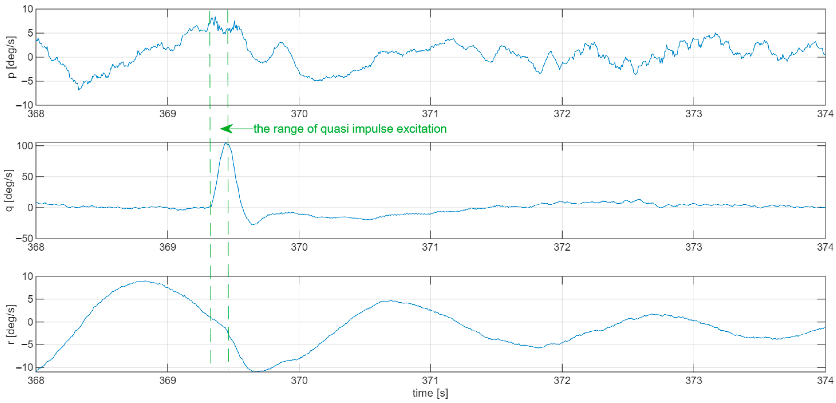
An upward deflection of the elevator (elevons) (negative sign) at 369.3 s lasted approximately 0.2 s. Free flight with the control surfaces in the neutral position occurred between 367 s and 374 s. The impulse excitation in the longitudinal channel caused a rapid increase in the pitch angular rate q, which momentarily exceeded 100 deg/s (Figure 25). After the control surfaces returned to the neutral position, the angular rate q returned to a value close to zero. The characteristics of the short-period oscillations and their damping are similar to those obtained from the calculations (simulated time period 0.6 s versus observed 0.5 s).
Figure 25.
Angular rates change after quasi-impulse excitation in longitudinal motion in Flight nb 3.
Figure 26 shows the onset of a speed phugoid associated with the long-period approximation in longitudinal motion. Due to the short duration of this test, only a single phugoid period was recorded, the length of which can be estimated at approximately 5 s. A subsequent flight was dedicated to the empirical determination of the aircraft’s phugoid characteristics (Section 6.3).
Figure 26.
Velocity change after quasi-impulse excitation in longitudinal motion in Flight nb 3.
6.2.2. Lateral Motion
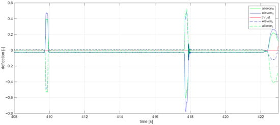
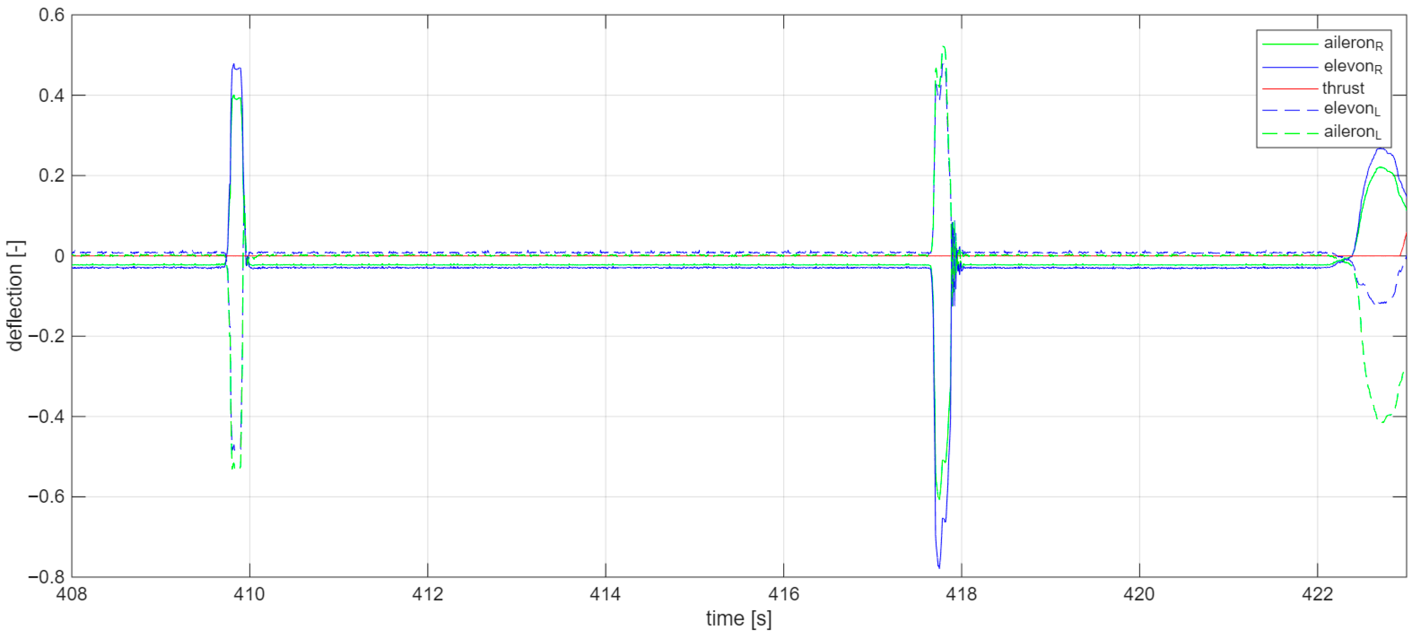
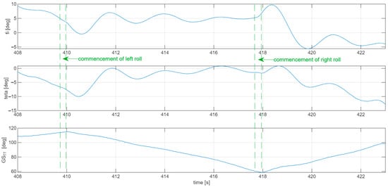
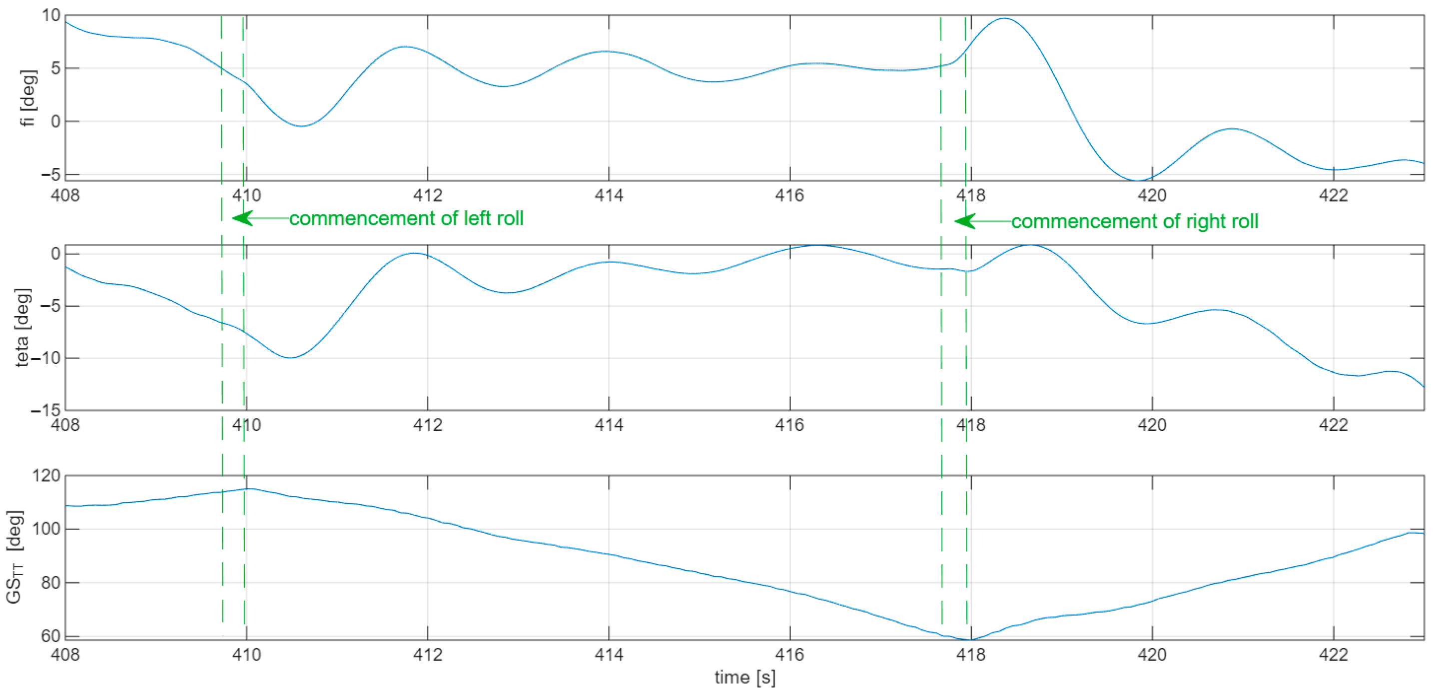
For the analysis of the aircraft’s roll motion characteristics, a segment of the flight was selected in which the control surfaces responsible for roll (ailerons and elevons) were deflected first to the left and then to the right. Figure 27 presents the applied control inputs.
Figure 27.
Quasi-impulse excitations in lateral motion in Flight nb 3.
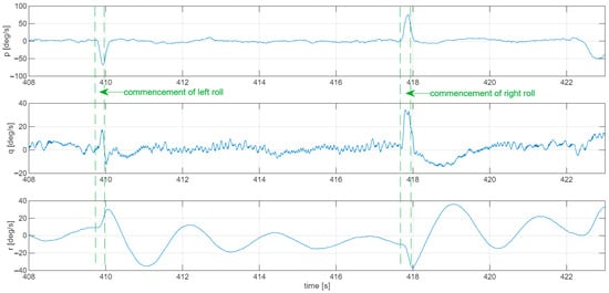
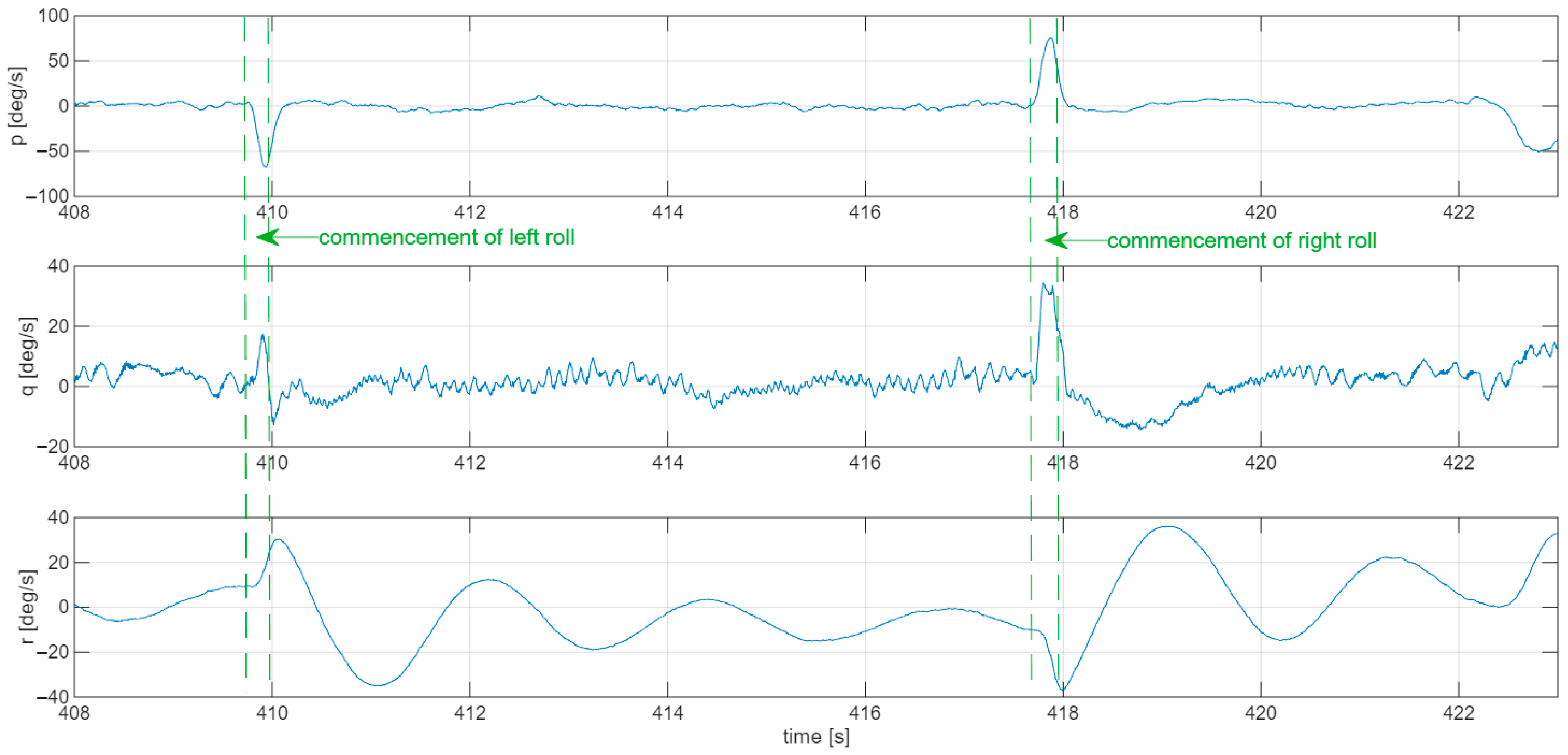
The flight segment from 408 s to 423 s was analysed. The first control input lasted 0.35 s, while the second acted over a similar, relatively short time interval of 0.38 s. Analysing the spatial orientation angles from the AHRS and the track angle from the GPS, it can be observed that the aircraft initially flew with approximately a 5° roll angle to the left wing, while nevertheless rolling to the right (Figure 28 and Figure 29). The deflection of the ailerons and elevons intended to increase the left roll initially caused a slight decrease, followed by a gradual increase in the left roll angle. The rolling motion was accompanied by an additional negative change in the aircraft’s pitch attitude.
Figure 28.
The influence of the roll channel excitation on the flying wing attitude in Flight nb 3.
Figure 29.
The influence of the roll channel excitation on the flying wing angular rates in Flight nb 3.
By observing other segments of the flight, the initially opposite response in the roll channel can be attributed to a gust of wind or turbulence that occurred just before the first control input. From 410 s until the input commanding a right roll, the aircraft changed its roll angle in an oscillatory but clearly damped manner, reaching a value of 5° to the left, while the heading (or, more precisely, the track angle) changed in the intended uniform manner. The deflection of the control surfaces in the opposite direction at approximately 418 s produced an analogous response and initiated a right turn.
The characteristics of the observed Dutch-roll oscillations and their damping are consistent with the calculated values (simulated period of 2.56 s versus 2 s observed).
6.3. Phugoidal Motion
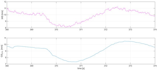
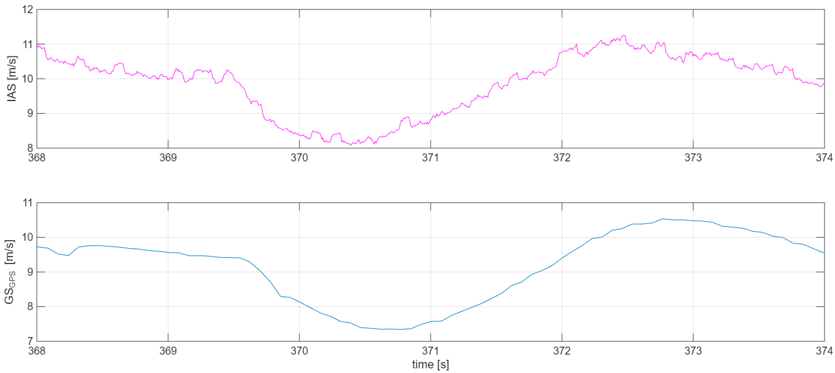
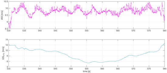
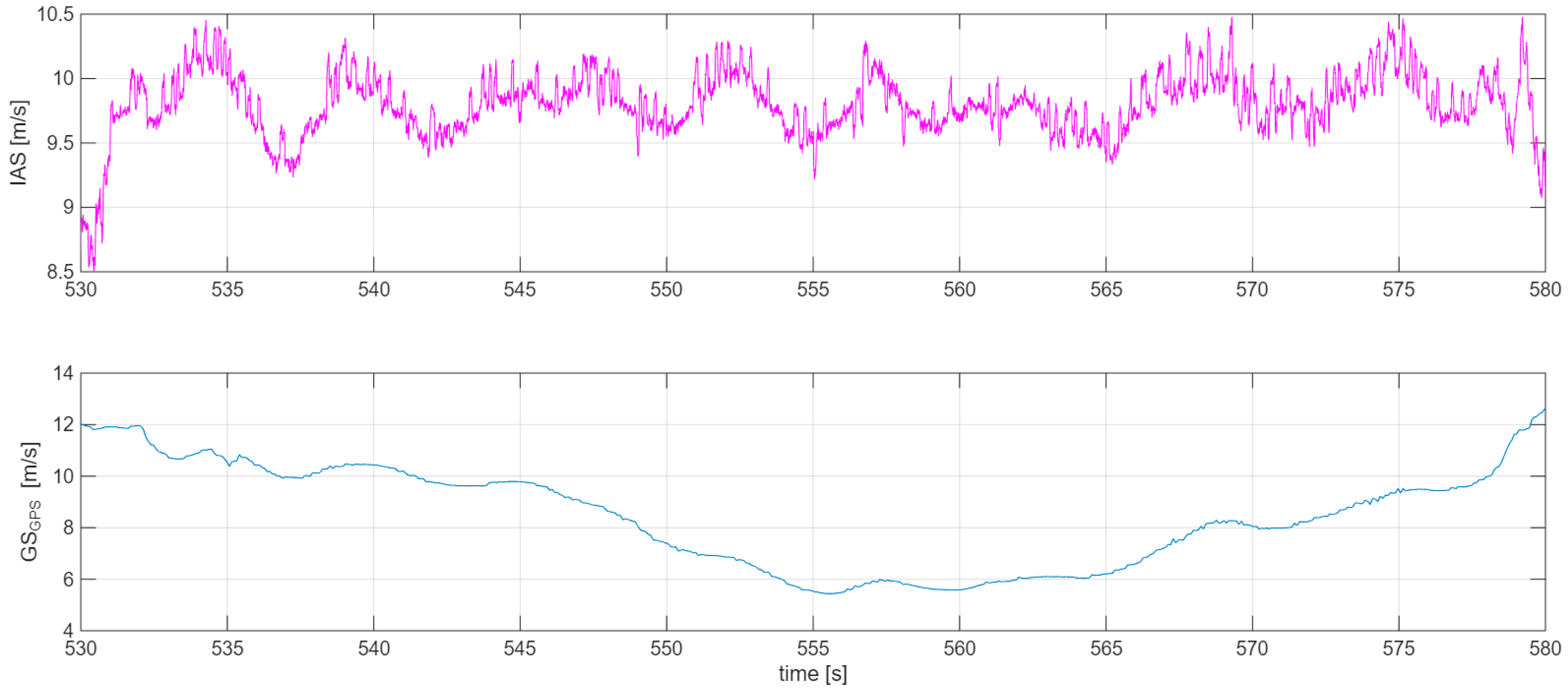
During the final flight, it was possible to perform a free flight lasting approximately one minute. This was a challenging task, as for a gliding aircraft flying at a speed of about 10 m/s, the distance covered amounts to 600 m, which in straight-line flight results in the two-meter wingspan leaving the pilot’s field of view. A headwind proved helpful in this case. During this segment of the flight, an oscillatory variation in the indicated airspeed (IAS) was observed, which is associated with phugoid motion (Figure 30). The phugoid period is consistent with the value determined in Section 6.2 and amounts to 5 s. The characteristics of the observed phugoid oscillations and their damping are also consistent with the calculated values (6.25 s simulated vs. 5 s observed).
Figure 30.
Flight speed phugoid recorded in Flight nb 6.
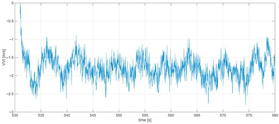
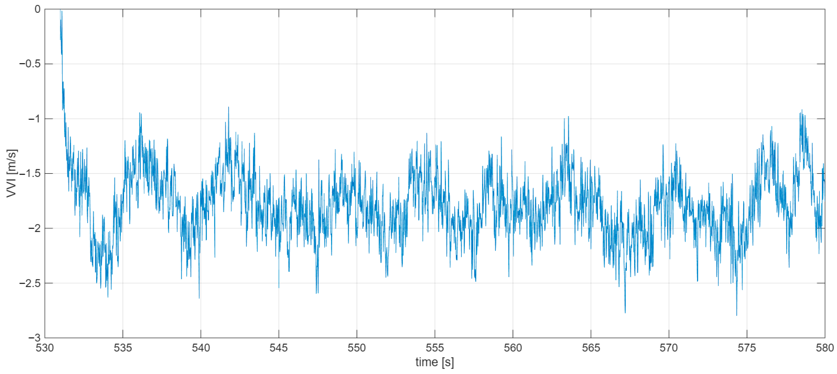
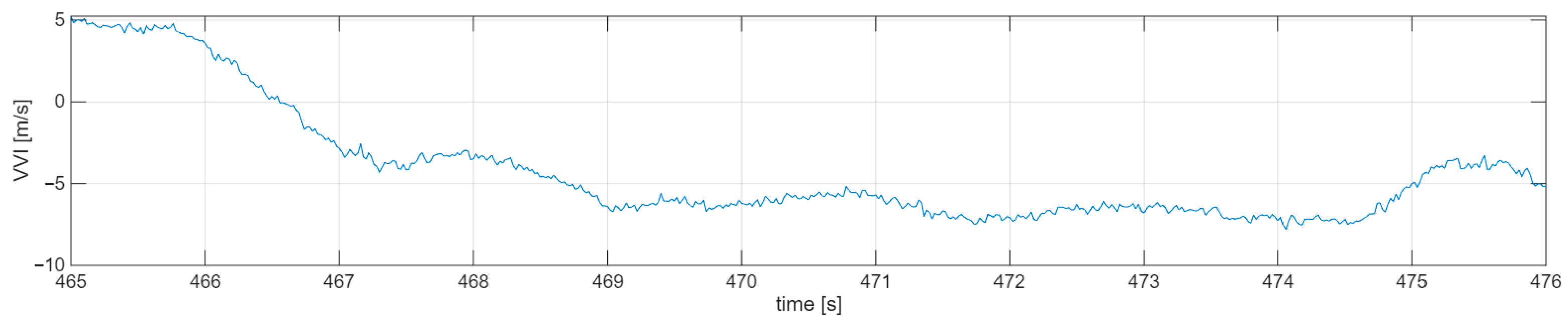
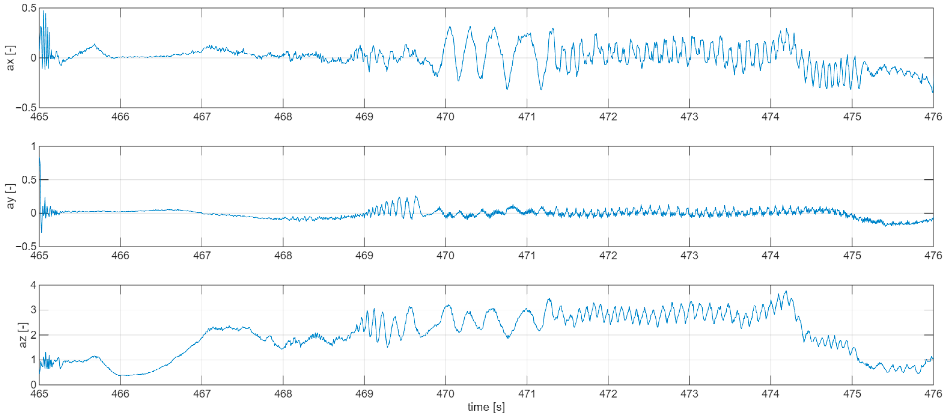
The flight speed oscillated within an approximate range of 9.4 to 10.3 m/s, which is close to the calculated cruise speed in gliding flight (10.5 m/s). The ground speed (GS) plot shows the influence of wind on this flight. Since the glide was initiated with a slight roll angle, the aircraft was drifted into the wind direction, allowing it to remain within the pilot’s field of view. Phugoid motion is also reflected in the vertical velocity (VVI); however, these values are affected by measurement noise of relatively large amplitude (Figure 31).
Figure 31.
Oscillations recorded by accelerometers in Flight nb 6.
6.4. Stalls
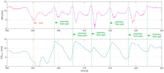
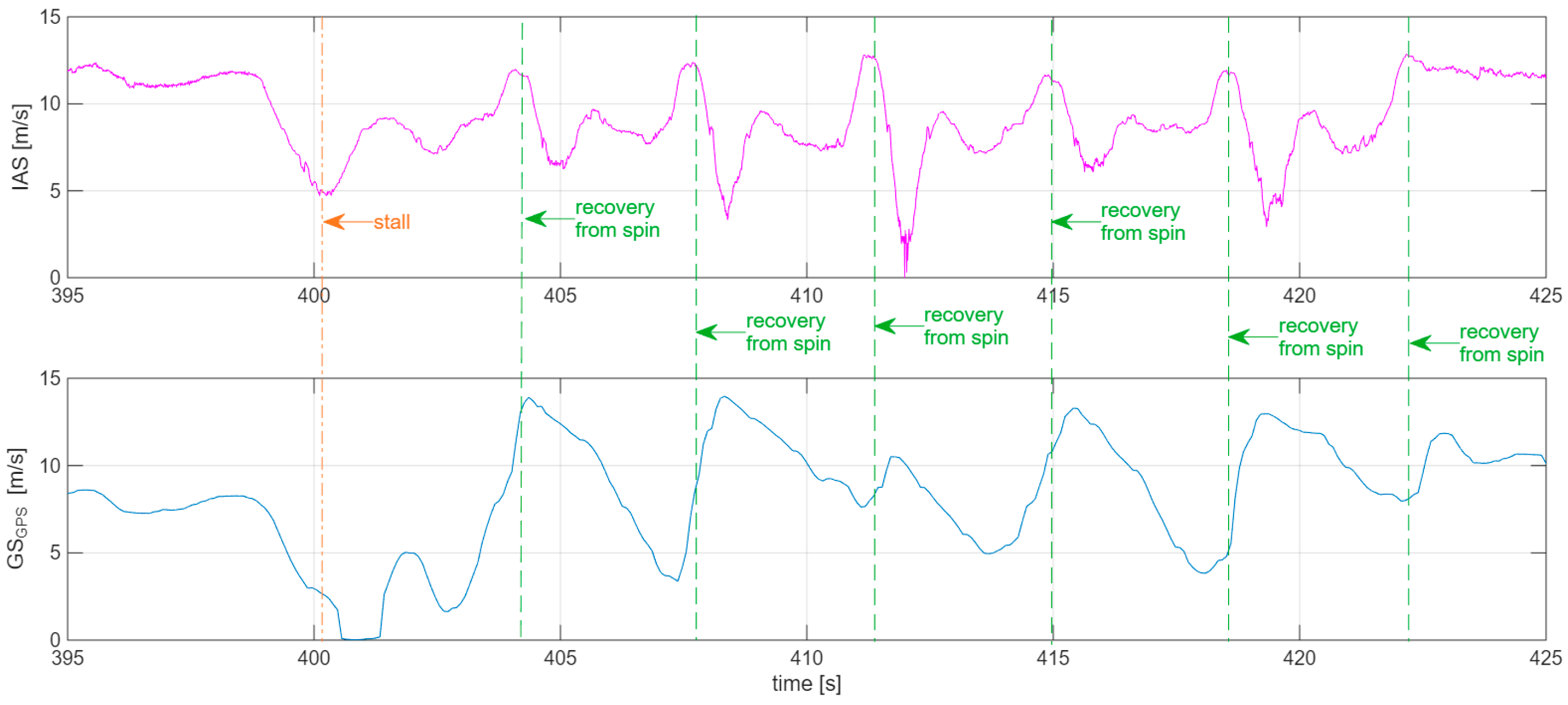
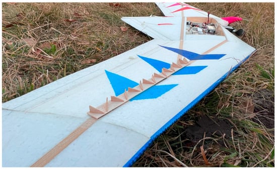
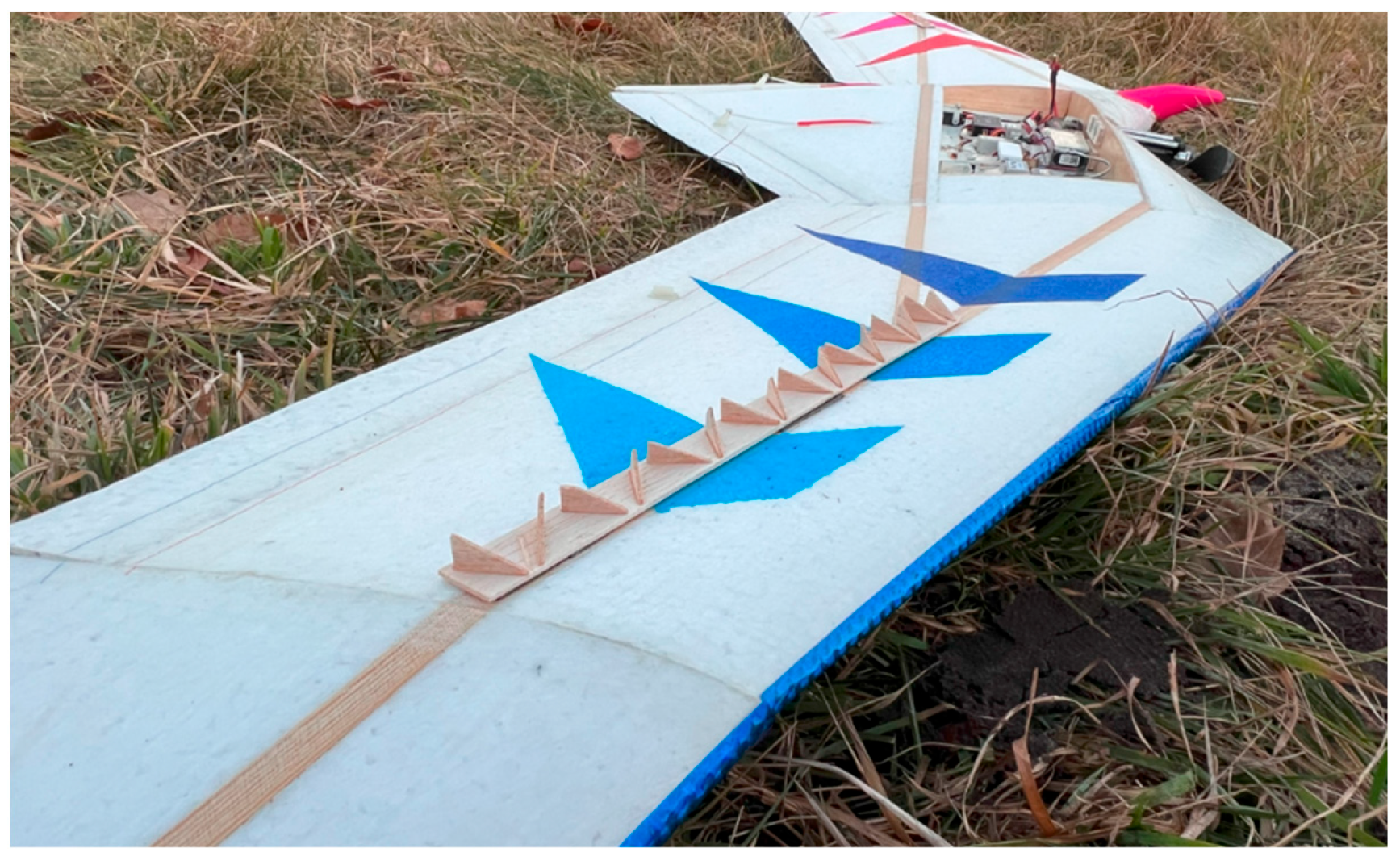
During the final two flights, a series of intentional stalls and attempts to induce a spin were conducted. The analysis of such phenomena is of key importance in determining whether the aircraft behaves in a safe manner. The first of the analysed stalls was induced by continuous, extreme upward deflection of the elevator (flight no. 5, Figure 32, Figure 33 and Figure 34). This was the first flight in which wing-mounted turbulators were applied (Figure 35). The course of the recorded airspeed changes is illustrated in Figure 32.
Figure 32.
Speed changes during stalls with the elevator fully deflected in Flight nb 5.
Figure 33.
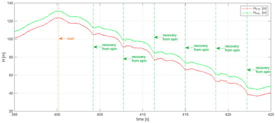
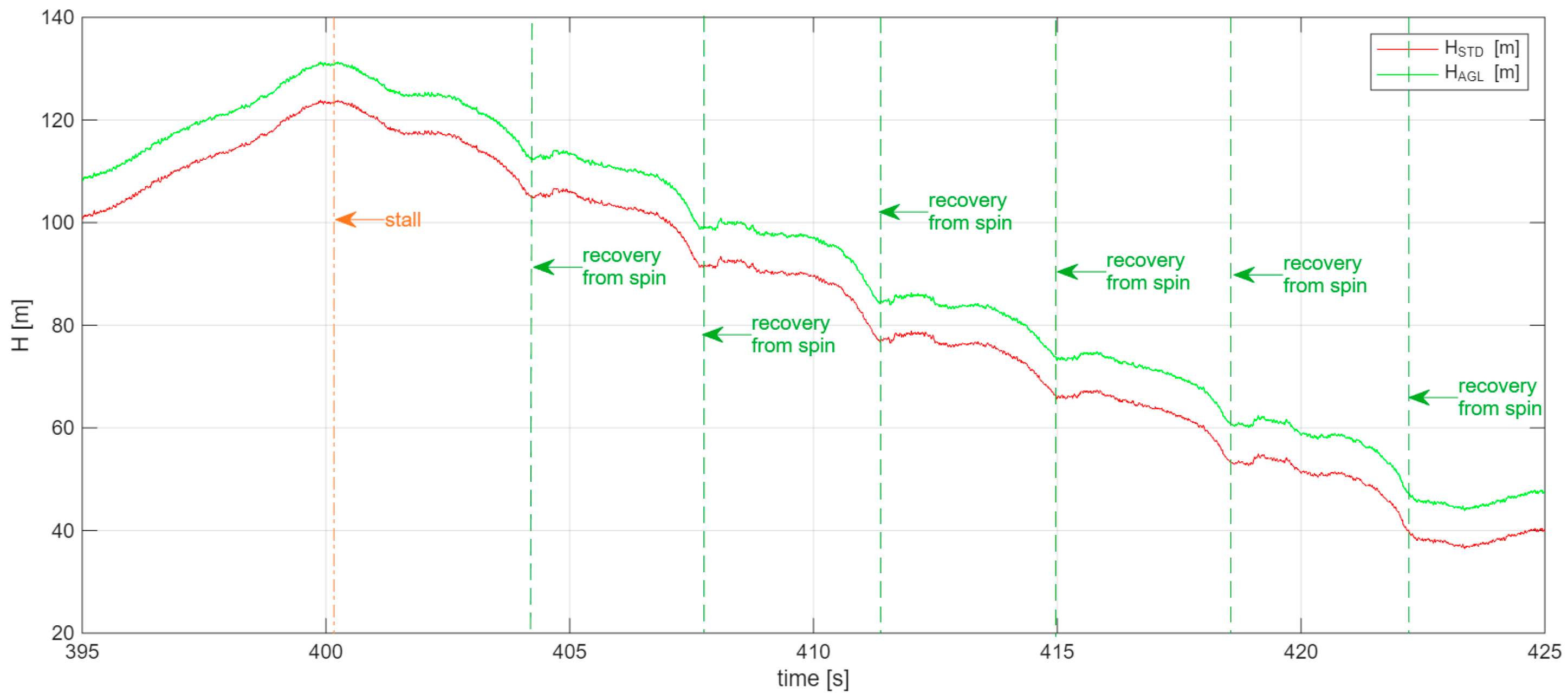
Altitude change during stalls with the elevator fully deflected in Flight nb 5.
Figure 34.
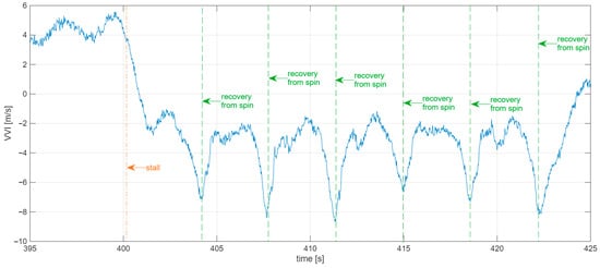
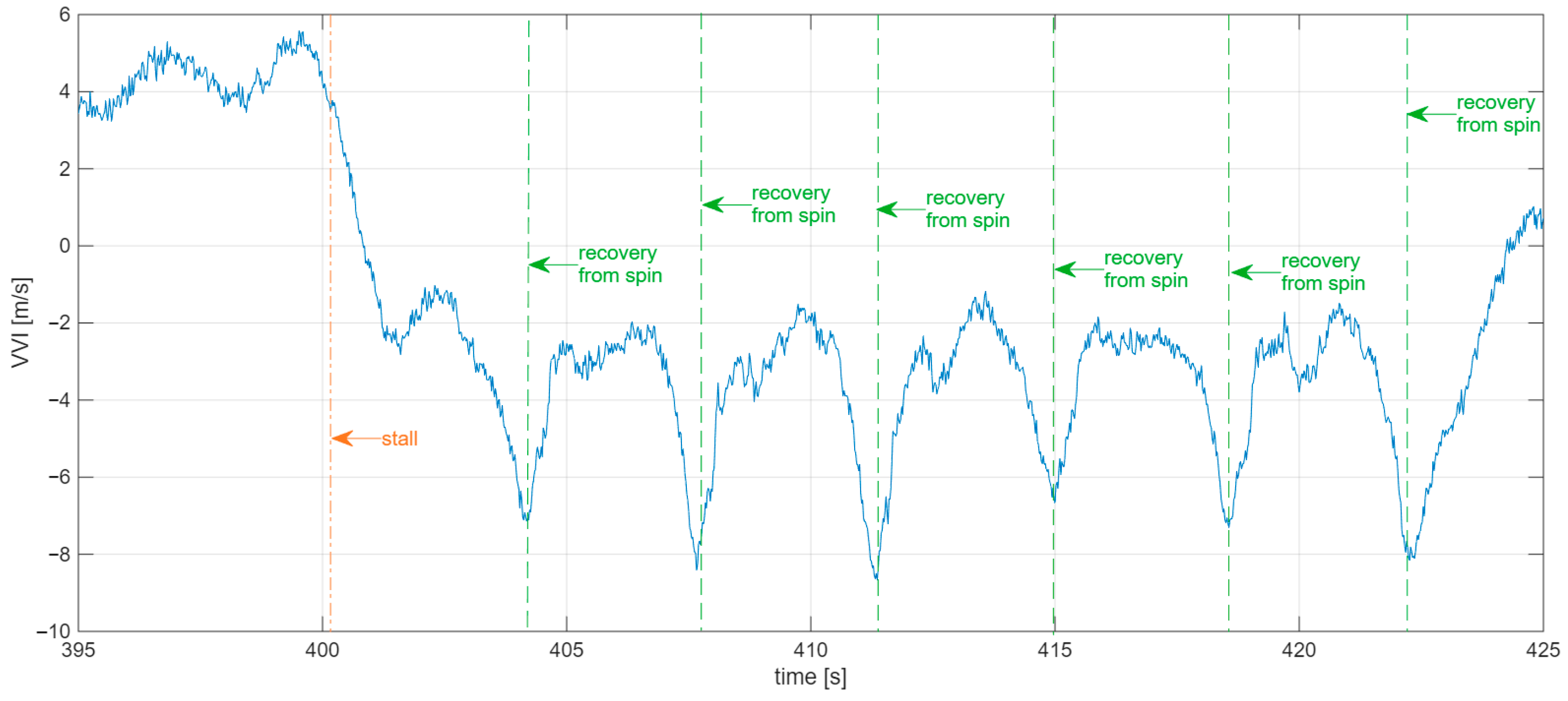
VVI during stalls with the elevator fully deflected in Flight nb 5.
Figure 35.
Wing-mounted turbulators.
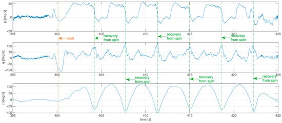
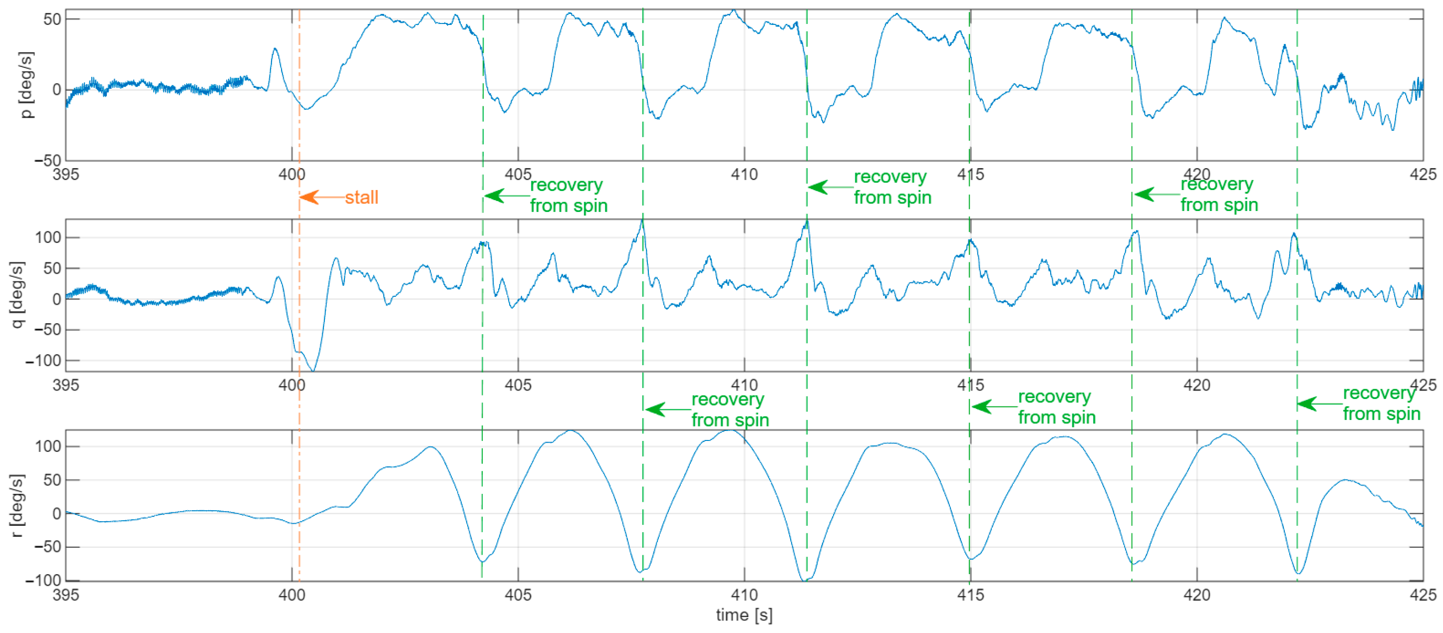
After the control surfaces were deflected, the aircraft lost airspeed and subsequently reached a stall condition at 400 s. In this state, the aircraft alternately exhibited pitching oscillations (“pumping”) and entered a spin, from which it recovered after completing one turn. The graph (Figure 32) shows that the stall occurred six times, at airspeeds close to the calculated stall speed value (5 m/s). The acceleration following the first stall occurred almost vertically (GS = 0).
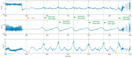
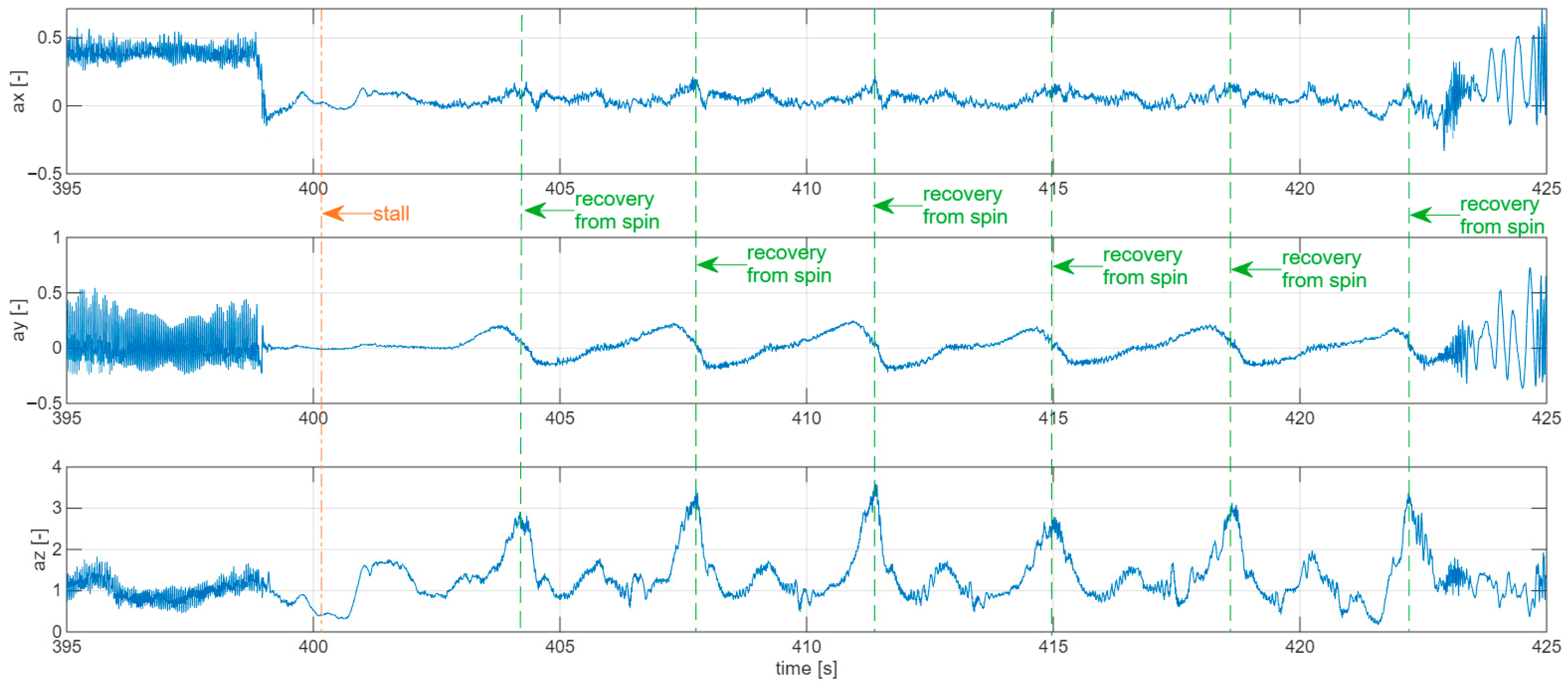
The altitude loss in each turn of the spin associated with the “pumping” motion was approximately 15 m (Figure 33). For a more comprehensive interpretation of the phenomenon, plots of VVI (Figure 34), angular rates (Figure 36) and accelerations (Figure 37) were added. The stall events are indicated on the plots by vertical dashed lines. At these moments, the pitch angular rates approached zero. Each stall was also accompanied by a rapid rotation in the yaw and roll channels.
Figure 36.
Angular rates during stalls with the elevator fully deflected in Flight nb 5.
Figure 37.
Accelerations during stalls with the elevator fully deflected in Flight nb 5.
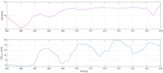
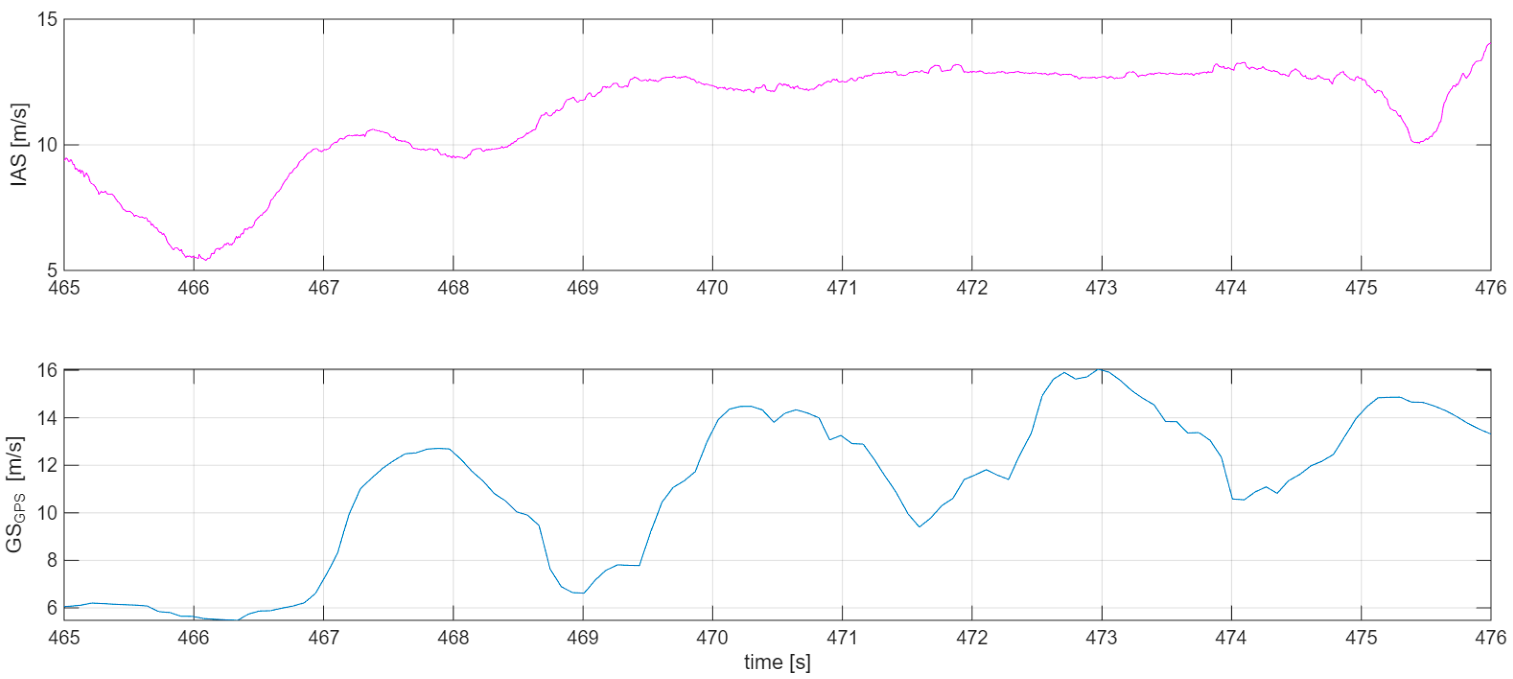
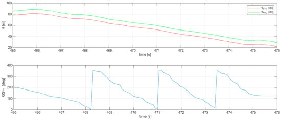
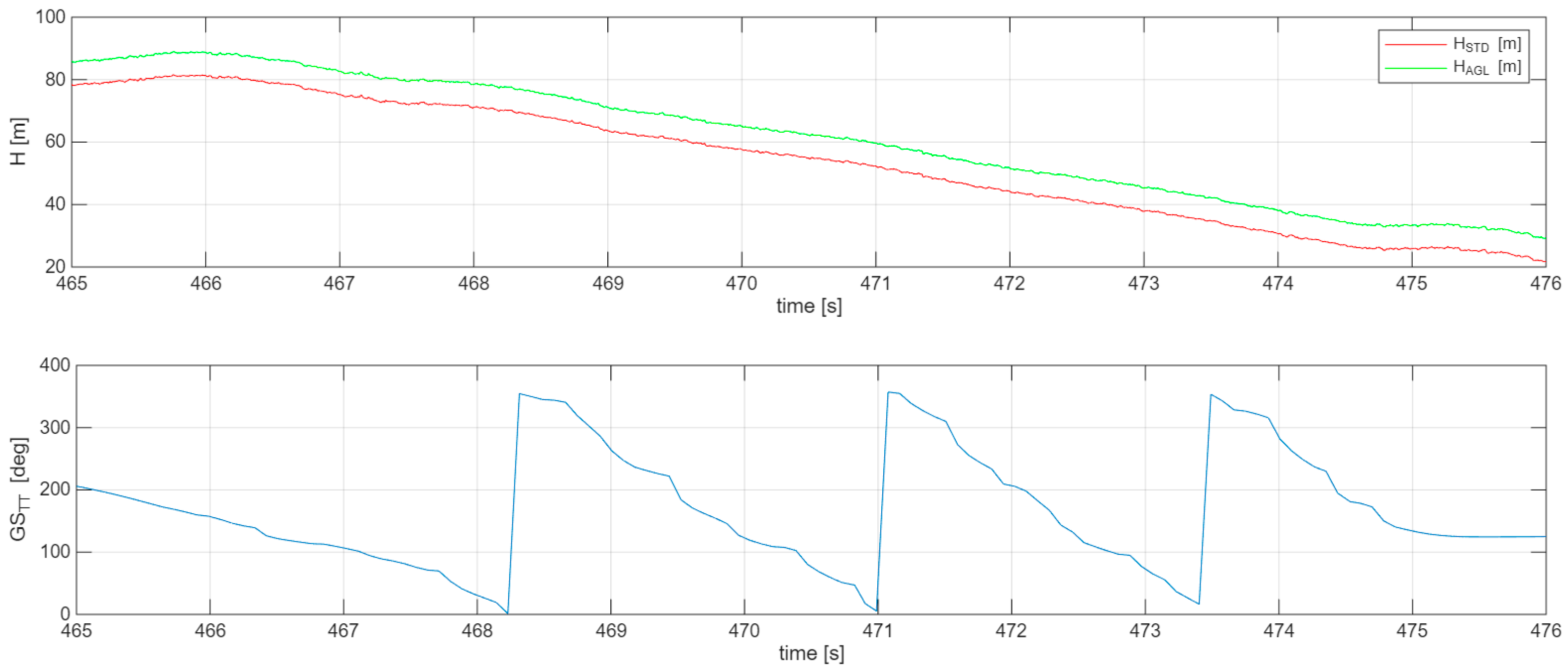
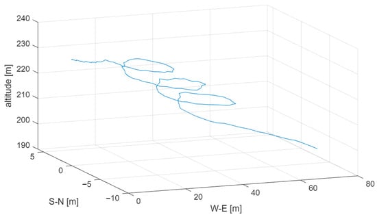
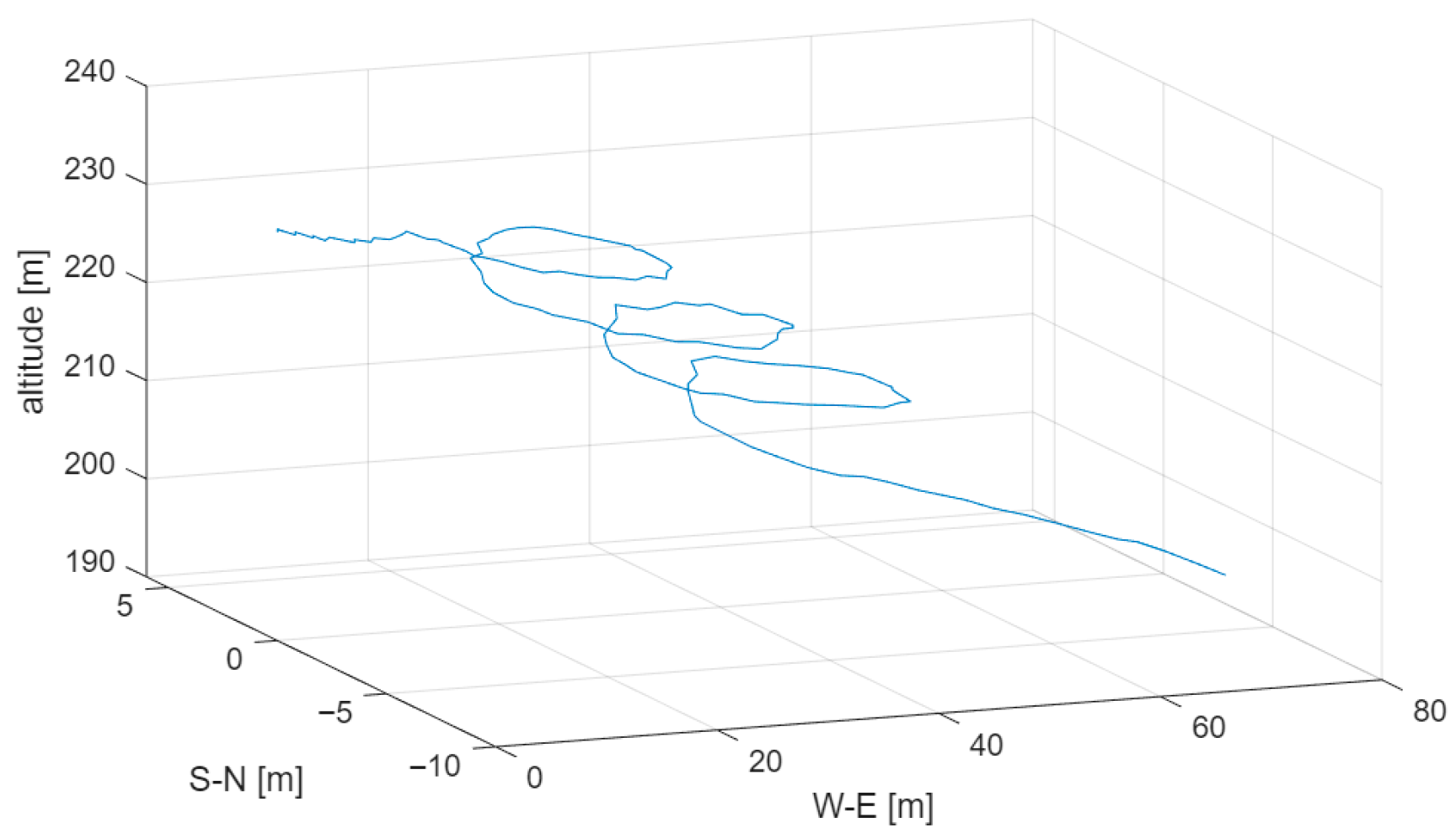
Figure 38 presents the time histories of IAS and GS in the case of a stall induced simultaneously by applying maximum pitch-up input along with left roll and left yaw inputs (data excerpt from flight no. 5). The stall occurred at 466 s of flight. Subsequently, an increase in IAS is observed, while the GS oscillates (Figure 38). Based on the recorded video footage, it was determined that the aircraft was in a spiral. The periodic variation in GS was influenced by wind. The changes in altitude and heading (or, more precisely in this case, the recorded true track) are illustrated in Figure 39. From this plot, it can be seen that the aircraft completed three full turns in the spiral, with each successive turn being performed in a progressively shorter time.
Figure 38.
IAS and GS during stall induced simultaneously by applying maximum pitch-up input along with left roll and left yaw inputs in Flight nb 5.
Figure 39.
Change in altidude and flight path angle during spiral in Flight nb 5.
Figure 40 shows the changes in vertical speed, the value of which gradually increases during the spiral. Accelerometer data (Figure 41) indicate a very high acceleration in the vertical axis relative to the longitudinal and lateral axes. The progressive rise in the az value during the spiral stems from the increased airspeed (Figure 38) required for tight-radius turns (Figure 42).
Figure 40.
Vertical speed during spiral in Flight nb 5.
Figure 41.
Accelerations during spiral in Flight nb 5.
Figure 42.
Trajectory of spiral in Flight nb 5.
6.5. Spins
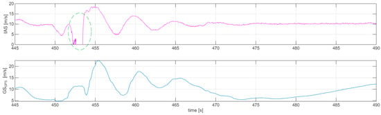
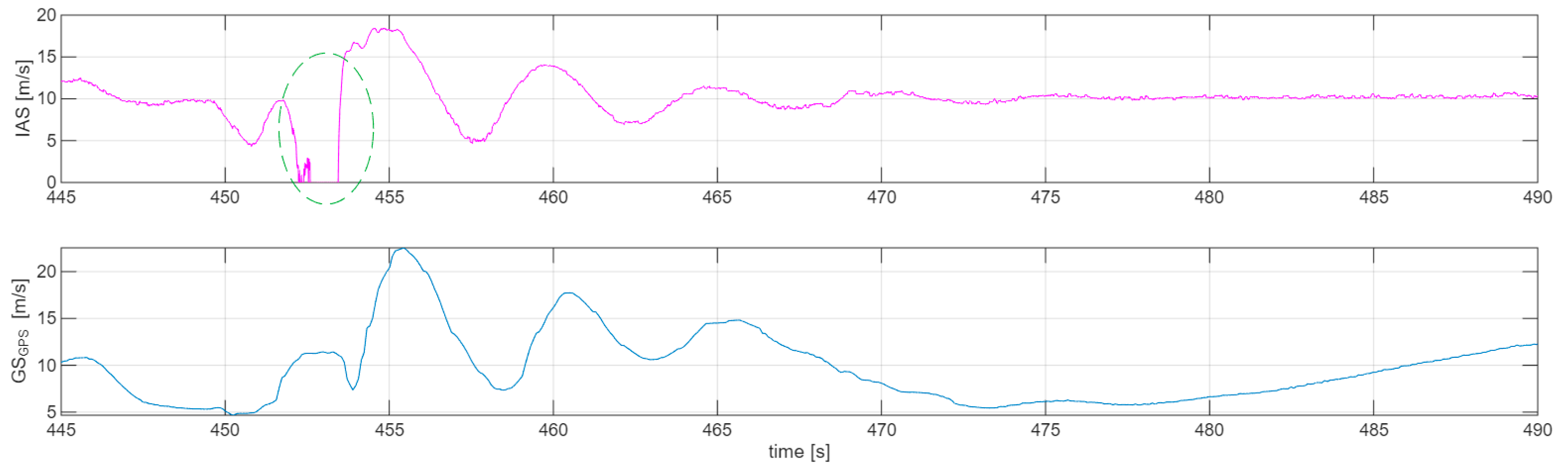
Finally, the behaviour of the model after entering a spin with the control surfaces set to neutral deflections was analysed. This scenario was executed during flight no. 6. Figure 43 shows the change in airspeed after entry into the spin. The aircraft reached the stall speed at t = 453 s of flight. Subsequently, an increase in airspeed is observed as a result of the pitching moment.
Figure 43.
Changes in speed after entering a spin in Flight nb 6.
The phenomenon marked with an ellipse in Figure 43 illustrates an interesting effect related to IAS measurement. At that moment, the indicated airspeed drops to zero, which may indicate oblique flow around the wing. If the flow angle at the Prandtl probe exceeds approximately 10–20 deg (depending on the probe design), the incoming streamlines no longer reach the total pressure sensor, and one of the four side ports of the tube captures a component of the total pressure. This results in an erroneous probe indication, and in reality the airspeed in the marked region can be interpolated between the airspeed values at the points where the curve intersects the ellipse.
At t = 455 s of flight, the aircraft reaches the maximum recorded airspeed of 18 m/s and then begins to decelerate during the climb. It subsequently approaches the stall condition again at t = 457.7 s of flight and, after two further “peaks,” stabilizes in gliding flight.
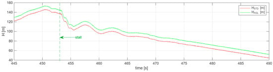
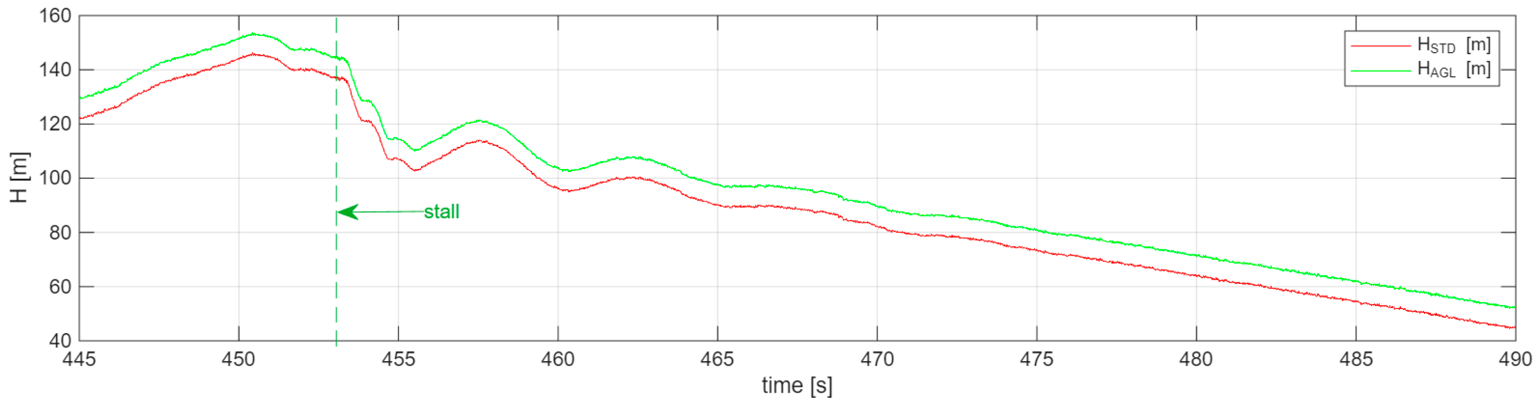
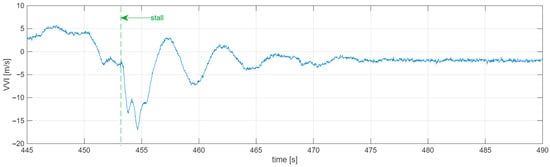
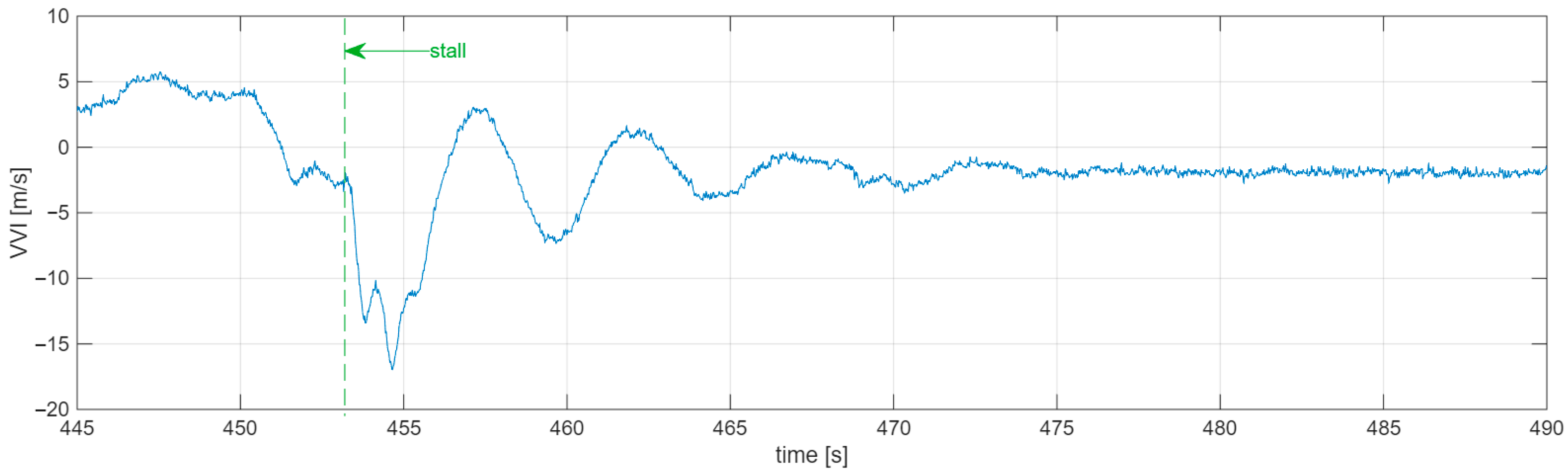
During the stall, the aircraft lost as much as 34 m of altitude until it stabilized and transitioned into steady gliding flight (Figure 44). The damping of oscillations lasted 15 s from the moment of the aircraft’s spontaneous recovery from the dive. As a complement to the analysis, the variation in the vertical speed VVI during the discussed segment of the flight is presented in Figure 45.
Figure 44.
Altitude variations during spin entry in Flight nb 6.
Figure 45.
VVI variations during spin entry in Flight nb 6.
7. Conclusions
Using simulations, it was possible to investigate the relationships between structural parameters and their influence on aircraft behaviour. Airfoil sections with a high critical angle of attack were applied; therefore, stall did not occur within the investigated range of angles of attack. However, because airfoils with a relatively high lift-curve slope Cl were selected, the final operational airspeeds of the aircraft turned out to be significantly lower than initially assumed. This resulted in lower Reynolds numbers characterizing the flow, which is particularly hazardous for the flow at the wingtips, where it was necessary to increase the chord and change the airfoil.
Wing sweep, which increased the longitudinal stability of the aircraft, proved to be a more important parameter than the Cm coefficient of the airfoil used at the wingtip; this made it possible to change the airfoil without significant losses in stability.
Wing dihedral, and in particular sections with negative sweep, noticeably increased longitudinal stability. Minimizing the dihedral, however, had a negative effect on longitudinal stability. This parameter influences directional stability to a lesser extent than longitudinal stability. Negative dihedral at the wingtip allowed for a reduction in longitudinal stability in that region while providing sufficient directional stability of the aircraft.
Wing twist not only enabled shaping the lift distribution along the wing to approximate an elliptical form, but changes in twist also affected the characteristics of Dutch Roll motion. In this way, negative twist at the wingtip proved to be the most advantageous solution in terms of lift distribution, stall characteristics, and increased directional stability.
A positive effect on the directional stability of a wingtip with negative dihedral and twist results from the fact that it produces significant drag during sideslip flow. During crosswind flight, the flow around this region occurs at a high angle of attack, which leads to the generation of a stabilizing moment caused by drag forces.
Flight tests showed that the model in its initial configuration was characterized by a tendency toward dynamic stalls. After introducing modifications, including shifting the centre of gravity and applying additional solutions to improve aerodynamic flow, better handling qualities and more stable flight were achieved.
Analysis of data obtained during test flights allowed an assessment of the model’s behaviour under various operating conditions. Measurements of Dutch Roll oscillations indicated that, in some configurations, lateral instability occurred, resulting in increased oscillations in the yaw channel. The introduction of turbulators on the wing surfaces effectively limited this phenomenon, improving the overall stability of the model and reducing the influence of external disturbances on its flight.
The recorded data also indicate specific behaviour of the model during the spin phase and after recovery. In particular, the analysis of angular rates and airspeed provided valuable information on the model’s ability to recover autonomously from this dynamic state. The conducted flight tests and obtained results indicate that the application of flow-organizing turbulators significantly increases the predictability and safety of the developed flying-wing configuration.
Author Contributions
Conceptualization, W.Z.; methodology, W.Z. and P.R.; software, W.Z., P.R. and Ł.W.; validation, W.Z., P.R. and Ł.W.; formal analysis, W.Z., P.R. and Ł.W.; investigation, W.Z. and P.R.; resources, W.Z., P.R. and Ł.W.; data curation, W.Z. and P.R.; writing—original draft preparation, W.Z., P.R. and Ł.W.; writing—review and editing, W.Z., P.R. and Ł.W.; visualization, W.Z., P.R. and Ł.W.; supervision, P.R.; project administration, P.R.; funding acquisition, P.R. All authors have read and agreed to the published version of the manuscript.
Funding
This research received no external funding.
Institutional Review Board Statement
Not applicable.
Informed Consent Statement
Not applicable.
Data Availability Statement
The original contributions presented in this study are included in the article. Further inquiries can be directed to the corresponding author.
Conflicts of Interest
The authors declare no conflicts of interest.
References
- Potsdam, M.; Page, M.; Liebeck, R. Flying-wing Body analysis and design. In Proceedings of the 15th Applied Aerodynamics Conference, Atlanta, GA, USA, 23–25 June 1997. [Google Scholar] [CrossRef] [Scilit]
- Nickel, K.; Wohlfahrt, M.; van Gierke, W. Tailless Aircraft in Theory and Practice; Butterworth-Heinemann: Oxford, UK, 1994. [Google Scholar]
- Zhang, L.; Huang, Y.; Zhu, Z.; Gao, L.; Chen, F.; Wu, F.; He, M. Virtual flight test of pitch and roll attitude control based on circulation control of tailless flying wing aircraft without rudders. Chin. J. Aeronaut. 2023, 36, 52–62. [Google Scholar] [CrossRef] [Scilit]
- Pan, Y.; Huang, J. Research on lateral-directional stability augmentation system of flying wing aircraft based on reliability model. Proc. Inst. Mech. Eng. Part G J. Aerosp. Eng. 2019, 233, 4214–4221. [Google Scholar] [CrossRef] [Scilit]
- Vlk, J.; Chudy, P. Adaptive Augmentation of an Unmanned Aerial Vehicle’s Flight Control System. In 2018 IEEE/AIAA 37th Digital Avionics Systems Conference (DASC); IEEE: New York, NY, USA, 2018; pp. 1–9. [Google Scholar]
- Hu, Q.; Feng, Y.; Wu, L.; Xi, B. A Nonlinear Adaptive Autopilot for Unmanned Aerial Vehicles Based on the Extension of Regression Matrix. Drones 2023, 7, 275. [Google Scholar] [CrossRef] [Scilit]
- Baran, H.; Bayezit, I. Advanced autopilot design with extremum-seeking control for aircraft control. Open Eng. 2024, 14, 20240044. [Google Scholar] [CrossRef] [Scilit]
- Tomczyk, A. Control Augmentation System for Remote Steering UAV. In Proceedings of the 28th Congress of the International Council of the Aeronautical Sciences (ICAS 2012), Brisbane, Australia, 23–28 September 2012; pp. 23–28. [Google Scholar]
- McCormic, B.W. Aerodynamics, Aeronautics, and Flight Mechanics; John Wiley & Sons: New York, NY, USA, 1979. [Google Scholar]
- Nowak, D.; Kopecki, G.; Orkisz, M.; Rogalski, T.; Rzucidło, P. The selected innovative solutions in UAV control systems technologies. In Innovative Control Systems for Tracked Vehicle Platforms; Springer: Berlin/Heidelberg, Germany, 2014; pp. 39–56. [Google Scholar]
- Bertran, E.; Sànchez-Cerdà, A. On the tradeoff between electrical power consumption and flight performance in fixed-wing UAV autopilots. IEEE Trans. Veh. Technol. 2016, 65, 8832–8840. [Google Scholar] [CrossRef]
- Aras, O.; Özbek, E.; Karakoc, T. Energy Consumption Profile of a Mini Electric UAV on Autonomous Flight Condition. In Proceedings of the International Symposium on Electric Aviation and Autonomous Systems, Budapest, Hungary, 20–21 July 2019. [Google Scholar]
- Stevenson, J.D.; O’Young, S.; Rolland, L. Beyond line of sight control of small unmanned aerial vehicles using a synthetic environment to augment first person video. Procedia Manuf. 2015, 3, 960–967. [Google Scholar] [CrossRef] [Scilit]
- Hou, Y.; Lv, M.; Liang, X.; Yang, A. Fuzzy adaptive fixed-time fault-tolerant attitude tracking control for tailless flying wing aircrafts. Aerosp. Sci. Technol. 2022, 130, 107950. [Google Scholar] [CrossRef] [Scilit]
- Petritoli, E.; Leccese, F.; Ciani, L. Reliability and Maintenance Analysis of Unmanned Aerial Vehicles. Sensors 2018, 18, 3171. [Google Scholar] [CrossRef] [Scilit] [PubMed]
- Lee, R. Only the Wing: Reimar Horten’s Epic Quest to Stabilize and Control the All-Wing Aircraft; Smithsonian Institution Scholarly Press: Washington, DC, USA, 2020. [Google Scholar]
- Davies, P. Northrop Flying Wings; Bloomsbury Publishing: London, UK, 2019. [Google Scholar]
- Wood, R.; Bauer, X. Flying wings/flying fuselages. In Proceedings of the 39th Aerospace Sciences Meeting and Exhibit, Reno, NV, USA, 8–11 January 2011; p. 311. [Google Scholar]
- Landell-Mills, M.N. Flying-Wing Aircraft Rethought, 2023. Available online: https://www.researchgate.net/publication/362960196_Flying-wing_aircraft_rethought (accessed on 28 February 2026).
- Gibbs-Smith, C.H. Aviation—An Historical Survey from Its Origins to the End of World War II; Science Museum/HMSO: London, UK, 1970. [Google Scholar]
- Maddock, A. A History of Manned Powered Flying Wing Development: 1922–1999. SAE Trans. 1999, 108, 1477–1493. [Google Scholar]
- Reed, D.B. Wingless Flight, The Lifting Body Story; NASA SP-4220: Washington, DC, USA, 1997.
- Traylor, J.W.R. Air Facts and Feats; Guinness Superlatives: London, UK, 1974. [Google Scholar]
- Lademann, R.W.E. Development of Tailess and All-Wing Glidrs and Airplanes; NACA TM No. 666; NASA: Washington, DC, USA, 1932.
- Liebeck, R.H. Design of the Flying-Wing Body Subsonic Transport. J. Aircr. 2004, 41, 16. [Google Scholar] [CrossRef] [Scilit]
- Kapkowski, J. Latające skrzydła klasy F1A F1A Class Flying Wings; Wydawnictwa Komunikacji i Łączności: Warszaw, Poland, 1981. (In Polish) [Google Scholar]
- Leishman, J.G. Introduction to Aerospace Flight Vehicles; Embry-Riddle Aeronautical University: Daytona Beach, FL, USA, 2023. [Google Scholar]
- Gudmundsson, S. General Aviation Aircraft Design: Applied Methods and Procedures; Butterworth-Heinemann: Oxford, UK, 2014. [Google Scholar]
- Raymer, D. Aircraft Design: A Conceptual Approach; American Institute of Aeronautics & Astronautics: Reston, VA, USA, 2018. [Google Scholar]
- Anderson, J.; Bowden, M. Introduction to Flight; McGraw-Hill Education: Columbus, OH, USA, 2021. [Google Scholar]
- Li, H.; Goodwill, T.; Jane Wang, Z.; Ristroph, L. Centre of mass location, flight modes, stability and dynamic modelling of gliders. J. Fluid. Mech. 2022, 937, A6. [Google Scholar] [CrossRef] [Scilit]
- Galiński, C. Wybrane zagadnienia projektowania samolotów (Selected Aircraft Design Issues); Wydawnictwa Naukowe Instytutu Lotnictwa: Warszawa, Poland, 2016. (In Polish)
- Gosak, J. Mechanika Lotu Modeli Samolotów—Teoria i Rozwiązania Praktyczne (Flight Mechanics of AirplaneModels—Theory and Practical Solutions); Oficyna Wydawnicza RC: Stefanowo, Poland, 2021. (In Polish) [Google Scholar]
- DeLaurier, J. Aircraft Design Concepts An Introductory Course; CRC Press: Boca Raton, FL, USA, 2022. [Google Scholar]
- Simons, M. Model Aircraft Aerodynamics; Fox Chapel Publishing: Mount Joy, PA, USA, 2025. [Google Scholar]
- Commission Implementing Regulation (EU) 2019/947 of 24 May 2019 on the rules and procedures for the operation of unmanned aircraft. Off. J. Eur. Union 2019, 152, 45–71.
- Mourad, M. Guidelines for XFLR5; André Deperrois: Normandie, France, 2009. [Google Scholar]
- Loya, A.; Maqsood, K.; Duraid, M. Quantification of Aerodynamic Variables Using Analytical Technique and Computational Fluid Dynamics. Int. J. Mech. Mechatron. Eng. 2018, 12, 991–997. [Google Scholar]
- D’Urso, S.; Martinez-Val Peñalosa, R. Flight Dynamics of the flying wing. In Proceedings of the 26th International Congress of the Aeronautical Sciences, Anchorage, AK, USA, 14–19 September 2008. [Google Scholar]
- Marques, P.; Da Ronch, A. Advanced UAV Aerodynamics, Flight Stability and Control Novel Concepts Theory and Applications; John Wiley & Sons: Hoboken, NJ, USA, 2017. [Google Scholar]
- Corda, S. Introduction to Aerospace Engineering with a Flight Test Perspective; John Wiley & Sons Inc.: Hoboken, NJ, USA, 2017. [Google Scholar]
- Torenbeek, E. Advanced Aircraft Design: Conceptual Design, Analysis and Optimization of Subsonic Civil Airplanes; John Wiley & Sons Inc.: Hoboken, NJ, USA, 2013. [Google Scholar]
- Cooper, G.E.; Harper, R.P. The Use of Pilot Rating in the Evaluation of Aircraft Handling Qualities; NASA TN D-5153; NASA: Huntsville, AL, USA, 1969.
- Wang, L.; Yang, K.; Zhao, P.; Yue, T. Aircraft Configuration Parameter Boundaries Based on Closed-Loop Flying Qualities Requirements. Aerospace 2021, 8, 360. [Google Scholar] [CrossRef] [Scilit]
- Heffley, R.K.; Jewell, W.F. Aircraft Handling Qualities Data; National Aeronautics and Space Administrative CR-2144; NASA: Huntsville, AL, USA, 1972.
- Campos, L.M.B.C.; Marques, J.M.G. On the Handling Qualities of Two Flying Wing Aircraft Configurations. Aerospace 2021, 8, 77. [Google Scholar] [CrossRef] [Scilit]
- Grzybowski, P.; Klimczuk, M.; Rzucidlo, P. Distributed measurement system based on CAN data bus. Aircr. Eng. Aerosp. Technol. 2018, 90, 1249–1258. [Google Scholar] [CrossRef] [Scilit]
- Rzucidło, P.; Kopecki, G.; Szczerba, P.; Szwed, P. Analysis of Stochastic Properties of MEMS Accelerometers and Gyroscopes Used in the Miniature Flight Data Recorder. Appl. Sci. 2024, 14, 1121. [Google Scholar] [CrossRef] [Scilit]



Disclaimer/Publisher’s Note: The statements, opinions and data contained in all publications are solely those of the individual author(s) and contributor(s) and not of MDPI and/or the editor(s). MDPI and/or the editor(s) disclaim responsibility for any injury to people or property resulting from any ideas, methods, instructions or products referred to in the content. |
© 2026 by the authors. Licensee MDPI, Basel, Switzerland. This article is an open access article distributed under the terms and conditions of the Creative Commons Attribution (CC BY) license.