


Abstract
Reducing the number of fuel injectors in hydrogen micromix combustors increases the loading of individual elements, creating challenges for flame separation and NOx control. This study numerically investigates two design approaches: air channel modification for elements widened from 3 to 4.5 mm, and a Micromix Side-Cooling Concept (MSC) with alternating fuel-fed and air-only channels. The numerical approach is assessed against published NOx measurements for a baseline configuration. Within the investigated range, air channel modifications alter mixing, recirculation, and lateral flame spreading. The optimised enlarged-element configuration predicts 1.40 ppm thermal NO at a global equivalence ratio of 0.54. At the same global equivalence ratio, MSC predicts 3.2 ppm thermal NO compared with 12.43 ppm for its reference configuration, both using 0.5 mm hydrogen injection holes. The MSC results show spatially separated OH reaction zones while retaining the same total air and hydrogen supply per unit frontal area and requiring 50% fewer hydrogen injection holes. These numerical findings indicate the potential of air channel modification and spatial fuel redistribution to reduce injector count while maintaining flame separation, with implications for NOx control.
1. Introduction
In recent decades, the growth of global aviation has brought economic benefits while also exacerbating environmental challenges. Conventional aviation kerosene remains the primary fuel, releasing CO2, NOx, and particulates that contribute to climate change and air pollution. Regulatory bodies such as the International Air Transport Association (IATA) have tightened emission targets, accelerating the search for cleaner alternatives [1]. The European Commission’s Flightpath 2050 report targets a 75% reduction in CO2 emissions per passenger kilometer by 2050 relative to 2000 levels [2]. Unlike fossil fuels, hydrogen combustion produces only water vapour, eliminating carbon emissions at the source. Its high gravimetric energy density (~120 MJ/kg) also offers a critical advantage for aero-engine applications [3].
However, integrating hydrogen into conventional gas turbine combustors presents fundamental difficulties due to its low density, wide flammability range, and low ignition energy. In particular, its flame propagation speed is several times higher than that of conventional fuels. As a result, in conventional swirl combustors, low-density hydrogen jets suffer from poor penetration and inadequate mixing, leading to locally fuel-rich zones, elevated temperatures, and increased NOx formation. While swirl can improve mixing, the high flame speed introduces significant risks of flashback and combustion instability. Therefore, novel injection and nozzle designs are essential for safe and stable hydrogen combustion.
1.1. Micromix Combustion Fundamentals
To address these issues, the concept of hydrogen micromix combustion technology was developed, as illustrated in Figure 1. By employing multi-injection element arrays, this approach breaks down large-scale flames into numerous micro-flames, promoting hydrogen–air mixing in each individual micromix element, reducing the extent of localised high-temperature regions, reducing residence time, and substantially lowering NOx emissions from hydrogen combustion. This micromix combustion concept was proposed by FH Aachen in the 1990s, establishing the foundational technology system of the micromix combustor [4]. To date, it has evolved to the sixth-generation design, during which the basic arrangement of multi-point micromix element arrays was established, followed by detailed geometric optimisation of injection elements, culminating in a relatively mature hydrogen combustion scheme in the sixth generation [5,6,7,8,9]. Beltrán et al. systematically reviewed micromix burner configurations, experimental investigations, and numerical modelling approaches [10]. Their review highlights the influence of injector dimensions and spacing on mixing, flame interaction, and NOx emissions, and identifies further configuration development and experimental assessment as important research needs.
Figure 1.
Micromix combustion concept: (a) micromix JICF mixing; (b) three-dimensional arrangement of micromix elements.
This concept has since been further developed by many research teams, leading to various hydrogen combustion technologies based on two core principles: “jet-in-crossflow (JICF) for enhanced mixing [11,12]” and “flame miniaturization to replace large-scale flames.” After decades of research on the micromix combustion concept (MCC), the flashback challenge in hydrogen combustion has been overcome. Current major challenges include combustion stability, flame characteristics, and NOx emissions resulting from the high flame temperature of hydrogen.
1.2. Laboratory-Scale Investigation
Laboratory-scale numerical and experimental studies have examined how injector geometry and fuel distribution affect micromix combustion. Researchers at Cranfield University have investigated micromix injector designs for hydrogen-fuelled aviation combustors. Through systematic investigation of the detailed geometric parameters of micromix injection elements—including air channel dimensions, hydrogen orifice size, and equivalence ratio—they found that the geometry of injection elements significantly affects flame behaviour and emissions [13,14,15].
The team at Beihang University studied the flow field and combustion performance of a pure hydrogen micromix diffusion combustor with radial triangular bluff bodies added inside the air channels before the hydrogen–air mixing location [16,17,18,19,20]. Numerical simulations of air-only, non-reacting hydrogen–air, and reacting hydrogen–air flows showed that adding the bluff body accelerates the decay of mainstream axial air velocity, allowing transversely injected hydrogen jets to interact with the airflow, generating counter-rotating vortex pairs and improving the mixing intensity between hydrogen and air. The results indicate that NOx formation is sensitive to bluff body geometric parameters; increasing the bluff body outlet height helps reduce NOx emissions [21,22].
The University of Illinois has developed a swirl-micromix configuration combining swirl and bluff body designs for methane–hydrogen blended combustion studies [23,24]. Multiple mixing element arrays form the combustor injection panel. Hydrogen is distributed through manifolds into individual tubes and injected through 24 orifices in the mixing zone. Air enters tangentially from below the mixing zone, forming swirling flow in an annular tube. Hydrogen is injected transversely into the swirling air, promoting intensive mixing. The mixture then flows past a bluff body at the exit, forming a stable recirculation zone. The tangential fuel injection method is used in this design to improve mixing quality while employing a bluff body to enhance flame stability.
Lei and Khandelwal investigated fuel injection strategies for micromix combustion elements. They found that for circular tube micromix structures, tangential fuel injection effectively increases the angular momentum of the air cross-section, enhancing mixing between the injected air and fuel, improving hydrogen combustion and shortening the length of the high-temperature region [25]. Sa et al. investigated a micro-mix combustor for stoichiometric H2-O2-steam (HOS) mixtures, achieving stable compact flames with lengths below 80 mm. Flame length increased with dilution ratio, jet velocity, and pressure. Elevated pressure enhanced turbulence-chemistry interaction, offsetting reduced laminar flame speed [26]. Luo et al. from Xiamen University studied the mixing and combustion characteristics of a single pure hydrogen micromix diffusion combustion element. They investigated different geometric parameters and equivalence ratios and found that the momentum flux ratio controls fuel penetration depth, thereby affecting mixing effectiveness and consequently influencing flame morphology [27].
Yang et al. studied interactions between multiple elements by comparing flow structures, species distributions, and NOx emissions for micromix designs with different inter-element spacings [28]. The results showed that spacing significantly affects flow structure and combustion characteristics. Excessively small spacing causes gas stream merging between nozzles, leading to increased axial velocity and reduced mixing intensity. Additionally, smaller spacing intensifies heat release concentration because independent flames begin to contact and merge, enlarging the high-temperature region and sharply increasing thermal NOx emissions.
In the paper by Folcarelli et al. [29], the geometric design of the mixing zone in micromix burners was investigated. By modifying the mixing zone configuration to a converging structure and conducting numerical simulations, they found that converging nozzles help reduce NOx emissions. Increasing the injector angle further enhances emission reduction. They also observed that such converging nozzles have a positive effect on preventing flashback.
Choi et al. [30] investigated a method to reduce nitrogen oxide (NOx) emissions in hydrogen combustion by inducing swirl via tangential fuel injection in a single nozzle. Results show that increasing the fuel-induced swirl number transforms the flame structure from a single integrated flame into a separated quadruple flame, which shortens significantly. The NOx emission index decreases linearly with the reduced residence time of combustion gases resulting from this structural change. The work demonstrates that flame separation, achievable through simple nozzle design adjustments, is an effective strategy for NOx abatement, providing insights relevant to micromixer combustor development.
Carmona et al. numerically investigated hydrogen–natural gas combustion in a micromix-type burner at equivalence ratios of 0.2–0.4 [31]. Their results showed that fuel composition affected flame length and temperature distributions, with flame merging observed under some higher-equivalence-ratio conditions. Increasing the hydrogen content reduced CO2 emissions but increased NOx emissions within the investigated range.
1.3. Industrial Applications
Alongside these laboratory-scale investigations, micromix and related multi-injection concepts have been developed for gas-turbine and industrial-burner applications. The micromix combustor jointly developed by FH Aachen and Kawasaki Heavy Industries (KHI) has entered the application verification stage. In 2018, KHI collaborated with FH Aachen to develop a 2 MW-class hydrogen dry low-emission gas turbine based on micromix combustion technology. The gas turbine was tested with pure hydrogen under 50–100% load conditions, and the reported NOx concentration was 35 ppm. In 2020, KHI demonstrated the world’s first pure hydrogen dry low-NOx power generation gas turbine [32,33].
GE developed a multi-tube mixer for high-hydrogen fuels, comprising an array of small-diameter air tubes surrounded by a fuel plenum [34]. Fuel is injected through small holes in the tube walls, promoting rapid jet-in-crossflow mixing within short premixing passages. The concept was experimentally evaluated in single-nozzle rigs and a full-scale multi-nozzle combustor can under F-class gas-turbine conditions [35].
Mitsubishi Hitachi Power Systems has combined swirl and staged combustion concepts to develop a Multi-Cluster Combustor. According to published studies, this combustor can successfully limit NOx formation, and Mitsubishi expects to achieve 100% hydrogen-fired gas turbine development by 2030 [36,37].
Lopez-Ruiz et al. conducted several studies on micromix combustors using hydrogen and blended fuels [38,39]. They studied a burner using hydrogen as fuel with micromix combustion technology to reduce NOx emissions and flashback risk. CFD simulations were performed under varying parameters, including energy density, air-fuel equivalence ratio, and air inlet temperature, to explore micromix combustion technology for industrial and domestic boiler applications. Numerical results were compared with experimental data from a geometrically scaled burner, and the results showed NOx values ranging from 4 to 14 ppm under specific conditions [40].
In summary, current international hydrogen combustion technologies are primarily based on the approaches described above. Most combustor domes adopt a multi-injection concept, which effectively mitigates localised high-temperature issues in hydrogen combustion while reducing flame size and residence time to lower NOx emissions. Another key aspect is mixing optimisation, with most approaches employing JICF designs to address insufficient hydrogen/air mixing over short mixing distances.
In micromix combustion, the miniaturized element design makes combustion performance highly sensitive to geometric parameters, as the internal structure governs flow field, mixing, and flame characteristics. Consequently, research should prioritise design optimisation and flow field analysis. At the macroscopic level, inter-element interactions are equally important, as overall flame behaviour directly determines emission characteristics and temperature distribution.
1.4. Relation to Previous Work
Previous studies have investigated micromix injector scaling, geometric optimisation, and flame interaction. Berger [41] examined scaling through increased fuel-orifice diameter and subsequent air channel modifications, whereas Lei et al. [42] investigated internal geometric parameters, including mixing distance and air channel height. Building on these studies, the present work investigates lateral flame spreading and emissions in micromix configurations with reduced injector density. The study examines element enlargement at matched thermal-input density, air-channel modifications under higher thermal loading, and spatial fuel redistribution using alternating fuel-fed and air-only passages. The numerical software used in this study was ANSYS Fluent 2022 R2.
The present simulations build on the mesh strategy and numerical model assessment reported in our previous study [42]. Figure 2 shows the baseline micromix element derived from FH Aachen’s fifth-generation design. The single-element flow domain shown in Figure 2b has frontal dimensions of approximately 3 mm × 10 mm and a hydrogen injection-hole diameter of 0.3 mm.
Figure 2.
(a) Schematic of a simplified micromix combustor. (b) Flow domain of a single micromix element.
Two complementary design investigations are presented. First, for elements widened from 3 to 4.5 mm, fixed-height width variations and an equal-area aspect-ratio comparison are used to examine how air channel geometry affects flow structure, lateral flame spreading, and predicted thermal-NO emissions. Second, the Micromix Side-Cooling Concept (MSC) is evaluated using alternating fuel-fed and air-only channels. For the same frontal area, the total air and hydrogen flow rates are maintained, while each remaining injector supplies twice the reference fuel flow. The contribution is a numerical assessment of this specific fuel-allocation arrangement and the associated changes in flame separation and thermal NO, together with geometric design insights for enlarged elements. The coefficient of variation (Cᵥ) of hydrogen mole fraction is used to quantify cold-flow mixing non-uniformity among the AC configurations, while the Ω vortex-identification criterion is used to examine the associated three-dimensional flow structures. These established diagnostics support the interpretation of how geometric modifications affect mixing, flame morphology, and predicted NO emissions.
2. Materials and Methods
2.1. Geometric Configuration and Scaling Strategy
The up-scaled burner investigated in this study is based on the baseline burner (3 mm × 10 mm) described above, with the burner width increased to 4.5 mm. This modification increases the lateral element width rather than uniformly scaling all geometric dimensions. As illustrated in Figure 3, within the same footprint of 9 mm × 10 mm, the baseline burner can accommodate three injectors side by side, whereas the up-scaled design requires only two injectors. Under this arrangement, the number of injection elements is reduced by one third. The 4.5 mm width is investigated as a representative case allowing two elements to replace three baseline elements within the same frontal area, rather than as an established optimum. To maintain the same energy density, the air and hydrogen mass flow rates per element are both increased by a factor of 1.5 relative to the baseline. Since the hydrogen-hole diameter and air channel dimensions remain unchanged in the initial up-scaled design (UD), the increased flow rates raise the injection and air channel velocities, motivating the subsequent investigation of mixing and flame behaviour.
Figure 3.
Schematic diagram illustrating the enlargement of dimensions.
Due to the increase in hydrogen mass flow rate, the fluid dynamics and vortex structure within the combustion zone are significantly affected. An excessive air flow rate can cause penetration difficulties, as the hydrogen momentum becomes insufficient to penetrate the high-speed air stream. Conversely, if the hydrogen jet momentum is too high, it may overshoot the air stream, leading to distortion and broadening of the combustion zone. Both scenarios result in incomplete mixing and localised hot spots, which destabilize flame anchoring and reduce combustion efficiency. As shown in Figure 4, the OH contour and velocity pathlines indicate that in the up-scaled cases, the small air channel leads to non-typical micromix flow structure: the hydrogen jet fails to effectively penetrate the air stream and fails to form the inner and outer vortices necessary for flame stabilisation.
Figure 4.
OH contour (left) and streamline plots (right) for the initial up-scaled case (for reference).
Jet-in-crossflow mixing is essential to micromix combustion, and the momentum flux ratio is a key design parameter. Therefore, this study optimises the air channel dimensions and hydrogen hole diameter for the scaled-up burner element. This approach serves two purposes: maintaining an appropriate momentum flux ratio J to preserve the characteristic micromix flow structure and limit flame merging.
Here, VH2 and Vair denote the hydrogen injection velocity and the air velocity through the air channel, respectively; and are the corresponding densities. The momentum flux ratio governs the jet penetration depth . According to the JICF study [43], the empirical constant α takes a value of 2, enabling preliminary estimates for each configuration. Penetration depth is a critical parameter in the jet-in-crossflow design of micromix combustors, as it largely determines the mixing quality and the resulting flow structure within the combustion zone.
2.2. Boundary Conditions and Design Optimisation
The computational geometries represent the fluid domains within the micromix burner. A velocity-inlet boundary condition was applied to the air inlet at 550 K, and a mass-flow-inlet boundary condition was applied to the hydrogen inlet at 300 K. The operating pressure is 1 bar absolute, with an atmospheric-pressure outlet. The upper, lower, and lateral domain boundaries are symmetry planes representing the rectangular test-burner arrangement. Physical burner surfaces are treated as adiabatic walls. Except for the initial BD and UD cases with 0.3 mm hydrogen injection holes, all configurations in the present scale-up study use 0.5 mm hydrogen injection holes. For the air-channel optimisation cases AC1~5, the hydrogen mass flow rate was varied to cover global equivalence ratios (φ) from 0.3 to 0.54. This operating strategy was adopted to examine the flame characteristics and emissions of the modified configurations under increased thermal loading.
The numerical framework was assessed against published experimental data for the baseline burner under atmospheric laboratory conditions. The derived configurations retain the same inlet temperatures and operating pressure, while their flow rates and thermal-loading conditions are specified separately in Table 1. The computational domains represent individual elements or representative repeating units of the rectangular test-burner array rather than a complete annular combustor.
The boundary conditions are listed in Table 1:
Table 1.
Geometric dimensions and inlet-flow conditions for the investigated configurations.
At φ = 0.54, AC1–AC5 operate at a common thermal-input density approximately 33% higher than BD/UD. Geometric effects are assessed within the AC group, while cross-group comparisons reflect overall configuration performance under the respective operating conditions.
To address the issues of flame merging and increased NOx emissions at higher equivalence ratios while preserving the essential characteristics of micromix combustion, this study proposes two aerodynamic control pathways for the scaled-up burner element:
Pathway 1: Single-Element Geometric Control
With the burner-element width fixed at 4.5 mm, five air-channel configurations with different areas and aspect ratios were designed and labelled AC1–AC5. Table 2 lists their geometric parameters and momentum flux ratios. Among these, AC5 and its derivative AC5-2 share identical flow passage areas, but their width and height dimensions are interchanged.
Table 2.
Design parameters of air channels and the momentum flux ratio at φ = 0.54.
Pathway 2: Micromix Side-Cooling Concept (MSC design)
The second approach modifies the spatial fuel-supply arrangement to promote flame separation at higher global equivalence ratios. As illustrated in Figure 5, the Micromix Side-Cooling Concept (MSC) supplies hydrogen to alternating elements, leaving air-only channels on either side of each active element. All channels share a common upstream air inlet. The term “side-cooling” describes the intended cooling and flame-confinement roles of these lateral air streams. Although no hydrogen is injected into the side channels, their air can mix with hydrogen-containing gases and contribute to downstream combustion.
Figure 5.
Micromix Side-Cooling Concept (MSC): (a) plan-view schematic and (b) three-dimensional schematic of the computational domain.
The computational domain of the MSC design consists of one central fuel-fed active channel and two half-width air-only side-cooling channels. In the computational domain, the nominal channel-width ratio is 0.5:1:0.5. Because the three air passages have the same height and are subjected to the same upstream inlet condition, the central active channel nominally receives 50% of the total air flow, while the two side-cooling channels together receive the remaining 50%. Hydrogen is supplied only to the central active element, whereas no hydrogen is injected into the side-cooling channels.
For the same burner frontal area, the MSC configuration maintains the total air and hydrogen flow rates of the corresponding baseline array, preserving the global equivalence ratio and thermal input density. With half of the injectors removed, the hydrogen flow through each remaining injector is doubled. Assuming area-proportional air distribution, the central fuel-fed channel receives half of the total air, giving a nominal active-channel equivalence ratio of 1.08 at a global value of 0.54. This estimate excludes side-cooling air entrainment and does not represent the actual pointwise equivalence ratio, which varies through mixing.
The air-channel exit position is defined as Z = 0, and the downstream direction corresponds to decreasing Z. Unless otherwise stated, sections labelled Z = −P mm are transverse planes normal to the Z-axis, located P mm downstream of the air-channel exit.
2.3. Numerical Setup
2.3.1. Computational Domain and Mesh Independence
For the BD, UD, and AC configurations, the computational domain contains one complete micromix element. For MSC, the domain contains one complete fuel-fed active channel and two half-width air-only side channels, as illustrated in Figure 5. As shown in Figure 6, structured hexahedral grids were generated using ICEM CFD 2022 R2 software, with local refinement applied to the core mixing and combustion regions as well as near-wall zones. The wall y+ values remained below 1 on the physical walls of the cases examined, consistent with resolving the viscous sublayer using the SST k–ω model. A grid independence study was conducted using four mesh sizes: 850,000, 1,350,000, 1,890,000, and 2,300,000 cells. The thermal NO and temperature distributions along the Z-axis of the combustor were compared. As shown in Figure 7, the results from all mesh sizes exhibit a high degree of overlap, indicating limited sensitivity of the plotted profiles to mesh refinement for the configuration examined. Relative to the finest mesh, the 1,350,000-cell mesh showed differences in outlet thermal NO and temperature at the sampled locations both below 1%. The mesh-sizing and local refinement settings established through this assessment were applied consistently across all configurations, with the total cell count varying with geometry.
Figure 6.
Representative mesh strategy of the computational domain.
Figure 7.
Mesh independence study: thermal NO and temperature distributions.
To balance prediction accuracy and computational efficiency, approximately 1,500,000 cells were used in all subsequent simulations.
2.3.2. Turbulence and Combustion Models
The Reynolds-averaged Navier–Stokes (RANS) approach was adopted for its favourable balance between computational cost and predictive accuracy, as widely validated in previous micromix combustion studies. The shear-stress transport (SST) k−ω model proposed by Menter [44,45] was selected for its superior performance in resolving near-wall flows. Both the air and hydrogen inlets were prescribed a turbulence intensity of 5% and a turbulent viscosity ratio of 10. Residual convergence thresholds were 10−4 for continuity, momentum, turbulence, and species equations, and 10−6 for energy. For the examined baseline case, the global mass, energy, and H2 balance errors were below 0.1%. Radiative heat transfer was included using the discrete ordinates (DO) model. For turbulent combustion modelling, both the finite-rate/eddy dissipation (FR/ED) model and the eddy dissipation concept (EDC) model were evaluated. The FR/ED model was selected for the subsequent reacting-flow simulations because its thermal NO predictions showed closer agreement with the experimental data for the baseline configuration under the conditions compared in Figure 8.
Figure 8.
Comparison of predicted thermal NO emissions with measured NOx or the selected reaction mechanisms.
2.3.3. Chemical Reaction Mechanism
Hydrogen reaction mechanisms were evaluated using the species transport model to calculate chemical reactions and species distributions during combustion. Seven hydrogen reaction mechanisms were initially screened and evaluated based on publication date, application breadth, and suitability. Three candidate mechanisms were further compared against experimental data [9] in Figure 8. Thermal NO emissions at the burner outlet were calculated at equivalence ratios ranging from 0.35 to 0.54. Based on the mechanism assessment and comparison with experimental data, the ELTE-2015 mechanism was selected for all subsequent simulations. It demonstrated excellent agreement with experimental measurements across all tested conditions [42].
The agreement with the baseline experimental NOx data supports the use of the adopted numerical framework for the present investigation. The same modelling approach is subsequently applied to the derived AC and MSC configurations, focusing on numerical predictions of the effects of air channel geometry and spatial fuel allocation on flow structure, flame morphology, and thermal NO formation.
2.3.4. NOx Formation Model
The extended Zeldovich mechanism was employed to predict NOx formation. Given that pure hydrogen diffusion flames contain no hydrocarbon radicals within the reaction zone, the contribution of prompt NOx via the classical Fenimore mechanism is entirely negligible. The extended Zeldovich mechanism has been used for engineering NOx predictions in hydrogen micromix and staged swirl combustors [15,21,46,47], including post-processing calculations on frozen flow fields. It is adopted here to evaluate thermal-NO formation and compare the investigated configurations; the absence of hydrocarbon radicals excludes conventional hydrocarbon-based prompt NO but does not establish that other non-thermal pathways are negligible. To predict its formation, Fluent applies the extended Zeldovich mechanism, comprising three elementary reactions. The thermal-NO formation rate is given by the following equation:
In the equation above, , , and are the forward reaction rate constants, and the reverse reaction rate constants are , and .
For the thermal-NO pathway considered here, burner design optimisation focuses on reducing high-temperature exposure and the residence time of hot gases. Following previous micromix design studies [4], the Thermal NOx model in ANSYS Fluent is used with the extended Zeldovich mechanism to assess geometric effects on emissions. The reported numerical emissions represent the thermal-NO contribution, rather than total NOx.
2.4. Data Analysis Methods
In this study, the outlet emission concentrations are reported in ppm on a dry basis and corrected to 15 vol.% O2. Both the pollutant and oxygen concentrations are expressed on a dry basis when applying the oxygen correction. To quantify fuel–air mixing within the micromix burner, the coefficient of variation () was introduced [48]. This metric provides a dimensionless measure of spatial dispersion, making it suitable for evaluating the uniformity of the hydrogen distribution across the plane. A lower value indicates a more uniform mixture, whereas a higher value signifies significant fluctuations and poor mixing quality. The expression for is shown below:
where is the mole fraction of H2 at sampling point , is the mean H2 mole fraction on the selected plane, and is the number of sampling points.
To identify and visualise the vortex structures in the present flow field, the Omega (Ω) vortex identification method proposed by Liu et al. [49] is employed. Unlike conventional eigenvalue-based criteria such as , , or , which are sensitive to user-specified thresholds and often fail to capture both strong and weak vortices simultaneously, the Omega method defines a vortex as a connected region where rotation dominates deformation. The Omega parameter is defined as:
where and are the symmetric (strain-rate) and antisymmetric (vorticity) parts of the velocity gradient tensor, respectively, and denotes the Frobenius norm. A small positive parameter is introduced in the denominator to avoid division-by-zero singularities and to suppress non-physical noise. An iso-surface of has been widely validated as a reliable choice for approximating vortex boundaries across various flow configurations without case-dependent tuning.
3. Results and Discussion
3.1. Scaling-Induced Challenge
For the baseline micromix burner with an element width of 3 mm (BD), its ultra-low NOx emission characteristic relies on the spatial independence of each miniature diffusion flame. However, when the burner operates at a higher equivalence ratio φ = 0.54, the increased fuel supply and volumetric expansion due to reaction heat release cause adjacent miniature diffusion flames to overlap spatially at the symmetry boundary, leading to flame merging.
As shown in Figure 9, within the same frontal area, the three micromix elements of BD exhibited flame merging as the equivalence ratio increased. As seen from the OH radical iso-surfaces in the reacting flow field and the species distribution at downstream cross-sections, flame merging causes the initially separate micro-flames to become laterally connected. The contact between adjacent flames at the boundary prevents fresh air from penetrating into the recirculation zone core. As a result, the local gas residence time increases and the peak temperature in the heat release zone reaches approximately 2450 K.
Figure 9.
(A) Comparison of OH contours between BD and UD at φ = 0.54. (B) OH iso-surface showing flame merging in BD.
Since the formation rate of thermal NO depends strongly on temperature, the localised high temperature raises the NO emission at the outlet to 16.75 ppm. Furthermore, the lateral connection of the reaction zones modifies the local flow and radical distributions near the burner head, which may influence local flame anchoring.
In contrast, for the up-scaled design UD, the single element width was enlarged by a factor of 1.5 to avoid flame merging, while the fuel injection hole diameter and air channel through-flow area remained unchanged. The downstream OH contours show that the increased lateral spacing physically separates adjacent reaction zones, reducing the peak temperature to 2370 K and predicted outlet thermal NO to 3.30 ppm.
However, directly enlarging the geometry causes downward flame deflection. During scaling, the air and fuel mass flow rates per micromix element must increase by a factor of 1.5 to maintain constant energy density. Since the air channel through-flow area remains unchanged, the air flow velocity and momentum rise significantly. When the element is widened without enlarging the air channel, the transverse hydrogen jet cannot penetrate the accelerated air stream sufficiently to produce the lift associated with the characteristic micromix flow structure. In the enlarged case UD, the air velocity is so high that the fuel jet cannot effectively lift the air flow, and its penetration depth decreases. The OH contours show a noticeable change in flame angle: the flame swings downward, and the reduced lift decreases the angle between adjacent upper and lower injection elements. The downward displacement brings the high-temperature reaction zone closer to the burner-head surface, indicating a potential increase in local thermal exposure. In addition, the smaller recirculation-supported reaction zone under the higher air momentum may reduce the flame-holding margin.
3.2. Parametric Study of Air Channel Geometry
3.2.1. Effect of Air Channel Width on Flow Structure and Flame Morphology
To address the momentum imbalance caused by physical size scaling in the above case—where excessive air velocity led to insufficient hydrogen jet penetration—the air channel width was increased while keeping the air channel height constant at 1.5 mm. Figure 10 shows the OH contours and streamlines at Z = −7 mm for air channel widths of 1.2 mm, 1.5 mm, and 1.8 mm under a typical operating condition of φ = 0.4.
Figure 10.
OH contours and streamlines for the widened air-channel designs at Z = −7 mm.
For the 1.2 mm configuration (W1), the high local air velocity tightly constrains the dual-vortex cores to the central side of the combustor axis, forming a compact elliptical shape. The OH reaction zone is locked within the strong shear layer at the vortex interface, leaving ample low-temperature air barriers on both sides and maintaining a safe distance from the symmetry boundary. When the width increases to 1.5 mm, the recovering momentum ratio J allows the hydrogen jet to penetrate deeper, stretching the counter-rotating vortex pair laterally and shifting the cores outward. This widens the mixing shear layer and causes the flame to extend outward. At 1.8 mm, the aerodynamic structure becomes distorted; the vortex structures on both sides are severely squeezed outward, and the excessively wide shear layer loses its lateral constraint on the flow field.
The OH species distribution directly reflects the drawbacks of this flow field distortion. The contour of W3 shows that the flame spreads laterally to both sides, covering the reference boundary of the micromix element. Although widening the air channel corrects the momentum imbalance and improves hydrogen jet penetration, it introduces the risk of flame merging due to the lateral expansion of the reaction zone. These results indicate that the increase in air channel width must be handled cautiously. In the optimisation of air channel dimensions, changing the width alone is not advisable. The air channel should be optimised by adjusting its aspect ratio under a fixed through-flow area, enabling independent control of hydrogen jet penetration and flame lateral spread.
3.2.2. Effect of Air Channel Geometry on Flow Structure and Mixing
Cold-flow simulations were performed for AC1–AC5 over φ = 0.3–0.54 before the reacting-flow simulations. These calculations quantified the effects of air-channel geometry on fuel–air mixing without reaction heat release or thermal expansion.
Figure 11 plots the coefficient of variation () of fuel mole fraction against equivalence ratio for all cases, quantifying spatial non-uniformity at Z = −5 mm, upstream of the combustion zone.
Figure 11.
Hydrogen–air mixing in AC1–AC5 as a function of the equivalence ratio.
Two clear trends can be observed from the curves in Figure 11. First, as the equivalence ratio increases from 0.3 to 0.54, the for all cases generally decreases, despite some isolated nonlinear fluctuations in certain configurations. This trend may arise because, under the current inlet settings, the air flow rate is held constant while the hydrogen flow rate increases with equivalence ratio. This raises the hydrogen injection velocity and progressively increases the fuel/air momentum flux ratio J. The higher-momentum jet penetrates deeper into the crossflow core, broadening the primary shear layer and reducing the spatial standard deviation of fuel concentration. This manifests as a converging trend. Second, the Cv curves clearly rank the mixing performance of different air channel geometries. The coefficient of variation increases in the following order, indicating decreasing mixing uniformity: AC5 < AC3 < AC1 < AC4 ≈ AC2.
The cold-flow of AC2 and AC4 lies in the high range of 1.15–1.46. This indicates that for air channel designs with relatively large areas (2.02 mm2 and 2.03 mm2, respectively) and limited vertical extent, the local time-averaged crossflow velocity is too low to excite high-density shear vortices in the near field, resulting in large-scale local fuel accumulation zones before ignition, and thus poor initial mixing.
Although the AC3 configuration achieves a good narrow-channel acceleration effect by limiting the width to 1.0 mm, bringing its overall within 0.72–0.93, it exhibits a local increase in the coefficient of variation near φ = 0.4.
In contrast, the AC5 configuration displays the most stable and globally lowest trajectory across the investigated range, with values continuously decreasing from 0.88 at φ = 0.3 to 0.68 at φ = 0.54. This fully demonstrates that the geometric boundaries of AC5 successfully construct an optimal shear strain rate field between the low-speed fuel jet and the accelerating crossflow, achieving the best scalar mixing uniformity.
3.2.3. Numerical Study of Air Channel Geometry Under Reacting Conditions
Figure 12 presents the OH contour cross-sections at Z = −7 mm (core reaction zone) for AC1–AC5 under various operating conditions, illustrating the evolution of flame contour extent with increasing equivalence ratio φ.
Figure 12.
Comparison of OH distributions at Z = −7 mm for increasing equivalence ratios.
At an equivalence ratio of 0.4, the flame width of all configurations remains within the acceptable range for the 4.5 mm burner. However, when the equivalence ratio exceeds 0.45, due to the effective through-flow area of AC1, AC2, and AC4 remaining at a high level of about 2 mm2, the local momentum of the air mainstream is relatively low, causing the vertical penetration depth of the fuel jet to be excessive. The reacting gases consequently undergo greater lateral thermal expansion. The flame gradually approaches the lateral boundary of the combustion zone, indicating an increasing risk of merging with adjacent combustion elements. At φ = 0.54, this risk becomes particularly pronounced. The micro-flame edges spread toward the symmetry boundaries on both sides of the single element, making contact and merging, connecting local high-temperature regions and driving a nonlinear increase in the thermal NO formation, consistent with the sharp rise in NO formation shown in Figure 13. In comparison, the AC5 design exhibits the best flame confinement capability, maintaining well-controlled flame width over the entire operating range from φ = 0.3 to 0.54. Cold air vortices wrap around the flame from above and below, providing effective thermal isolation and cooling for the high-temperature reaction zone.
Figure 13.
Predicted thermal NO emissions for the AC configurations.
In all cases, OH radicals extend into the lower region of the burner, indicating that heat release diffuses into the outer recirculation vortex. Therefore, the temperature in the lower part is significantly higher than that in the upper part. This phenomenon is particularly evident in cases AC1 to AC4, where the high temperature inside the outer vortex weakens the cooling effect on the combustion zone and may adversely affect the thermal durability of wall materials.
To quantitatively evaluate the emission reduction capability of each design, all cases were simulated over the equivalence ratio range of 0.3–0.54, and the outlet thermal NO concentrations are plotted in Figure 13. As shown, there are significant differences among the five configurations. Within the AC series, AC5 gives the lowest predicted outlet thermal NO concentration, at 1.40 ppm for φ = 0.54, compared with 5.23 ppm for AC4. This comparison reflects the effects of the investigated air-channel geometries under the common operating conditions of the AC series.
Notably, the emission curves of cases AC2 and AC4 almost coincide, and these two designs exhibit the highest emission levels in the group. Within the investigated configurations, the predicted NO emissions highly depend on the combined effects of air-channel area and shape, since the air channel area controls the velocity of the air stream mixing with the hydrogen jet, and the resulting mixing intensity directly affects thermal NO formation. Furthermore, the lower predicted thermal-NO emissions of AC3 and AC5 suggest potential benefits of their air-channel geometries for NOx control.
Near the channel exit, where the streams intersect, the thickness of the air flow can be approximated by the channel height. For cases AC1 to AC5, the penetration ratio—defined as the injection depth normalised by the channel height—was calculated. By incorporating the momentum flux ratio and injection depth data from Table 2, the penetration ratios for all cases were determined and are listed in Table 3.
Table 3.
Comparison of injection depth, penetration ratio, and thermal NO emissions at φ = 0.54.
It was found that when the momentum flux ratio is appropriate and capable of sustaining the typical micromix vortex structure, thermal NO emissions exhibit a direct correlation with penetration ratio. In these cases, a reduction in penetration depth generally led to lower emissions. However, this relationship is not absolute and is more directly influenced by the air channel dimensions and design. For instance, in Cases AC3 and AC5, despite sharing the same penetration ratio, the smaller penetration depth in AC5 resulted in a superior emission reduction effect.
3.3. Decoupling the Effect of Aspect Ratio
To gain a deeper understanding of the role of the air-channel aspect ratio in governing the flow structure, a further study was conducted targeting an air channel area of 1.6 mm2. The aspect ratio (AR), defined as the ratio of air channel width to height, was modified from 0.625 to 1.6, as shown in Figure 14, while keeping the momentum flux and air velocity unchanged. Both designs were simulated at the design point φ = 0.4 and the higher-equivalence-ratio condition φ = 0.54, and their emissions and temperatures were compared.
Figure 14.
Air channel geometries with aspect ratios of 0.625 and 1.6.
3.3.1. Thermal NO and Flow Field Comparison
First, the NOx emissions of the two designs were compared. For AR = 0.625 and AR = 1.6, the thermal NO emissions at φ = 0.4 are 0.32 ppm and 0.25 ppm, respectively, and at φ = 0.54 they are 1.4 ppm and 1.59 ppm, respectively. The two equal-area configurations produce similar absolute emission levels despite differences in flow structure. Together with the AC1–AC5 results, this suggests that air-channel area is an important design parameter within the investigated range, although the available comparisons do not establish its general dominance over width, height, or aspect ratio. Both modified designs exhibit excellent thermal NO reduction capability, with emissions controlled at very low levels, meeting the design targets.
Using the Ω criterion described above, the flow field structures of these two cases were investigated. Figure 15 shows the three-dimensional vortex structures represented by the Ω = 0.52 iso-surface, with the temperature distribution mapped onto the surface. It can be seen that the inner recirculation zone of AC5 is longer overall, but because the air channel is narrower, the upstream counter-rotating dual vortices are aerodynamically compressed in the lateral direction, causing the vortex cores to converge toward the centre and resulting in a more slender strong-swirl boundary.
Figure 15.
(a) Ω = 0.52 iso-surfaces in case AC5, (b) Ω = 0.52 iso-surfaces in case AC5-2.
In contrast, in the AC5-2 case, the entire inner vortex appears fuller, and the overall recirculation structure is more complete, forming a clear boundary with the shear layer. Due to the better penetration ratio of hydrogen, the overall air flow lift effect is more pronounced, and the outer recirculation zone expands laterally and longitudinally. This enlarged outer vortex produces a strong convective circulation loop on both sides of the element, forcing the OH diffusion fronts on either side of the reaction core to fold inward toward the central axis.
3.3.2. Thermal Field and Flame Morphology
Figure 16 and Figure 17 show the combustion conditions at the design point φ = 0.4 and the higher-equivalence-ratio condition φ = 0.54. Temperature and OH contours on the Y-Z mid-plane of the combustor are presented for comparison between cases AC5 and AC5-2.
Figure 16.
Comparison of temperature and OH contours at φ = 0.4.
Figure 17.
Comparison of temperature and OH contours at φ = 0.54.
From the temperature contours at φ = 0.4 and φ = 0.54, it can be seen that the main high-temperature region is located near the flame. Hot gases recirculate into the outer vortex, and the temperature in the lower part of the combustion zone stabilises at about 1550 K at φ = 0.4. The outer vortex temperature of AC5-2 is about 20 K lower than that of AC5. This difference is very small and cannot be clearly distinguished from the contour plots. This may be because the outer vortex size of AC5-2 is significantly larger than that of AC5, as shown by the velocity streamlines in the figures. A larger vortex allows more downstream gas to contribute to cooling.
In the modified design AC5-2, the temperature level of the inner vortex differs noticeably from that of AC5. The cyan region in AC5 (Figure 17) indicates that heat has diffused into the inner vortex area, with a temperature of about 1500 K, posing a potential risk to the structural safety of the combustor. From the Ω = 0.52 iso-surface plot, it can also be seen that the inner vortex region of AC5-2 remains below 1200 K. This is because the vertically injected hydrogen jet cannot effectively penetrate the air stream; the insufficient outer vortex scale and lift distance result in a longer inner recirculation zone, causing downstream heat release to enter the inner recirculation zone along the flow path, forming a high-temperature region of 1200–1500 K near the inlet panel.
Combining the OH and temperature contours, it is evident that at lower equivalence ratios, the flames in both designs are clearly separated, avoiding the risk of flame merging. At φ = 0.54, the flame sizes of both designs increase, but this is still acceptable for the 4.5 mm design. In the design with a lower air-channel height, the high-temperature flame at the higher equivalence ratio tends to fold inward because the air flow from the inner vortex compresses the shear layer anchoring the flame. This prevents high temperature from penetrating into the inner vortex and causes the flame to fold inward.
Examining the OH distribution contours and streamlines at successive transverse sections along the Z-axis for both cases in Figure 18 reveals that, while the aspect ratio has a marginal effect on emissions, it exerts a pronounced influence on the flow field structure. Despite the wider air channel of AC5-2, the lateral flame size is actually smaller than that of AC5. The streamline plots offer further insight: in AC5-2, although the momentum ratio remains unchanged, the lower air channel height gives the hydrogen jet a higher penetration ratio. This enhanced penetration actively pushes and stretches the upper recirculation vortex core laterally while shifting it upward.
Figure 18.
Comparison of OH contours at successive transverse sections along the Z-axis.
Consequently, the downstream large-scale outer recirculation vortex expands in both the longitudinal and lateral directions, causing the shear layer to lift as a whole. This prevents the flame from swinging downward and forming a high-temperature region near the wall. Moreover, due to the enlargement of the outer recirculation zone, the reaction core does not spread horizontally as the air jet widens. Instead, it is lifted upward along the trajectory supported by the outer vortex, forming a compact reaction core and reducing the lateral flame extent. At the core reaction zone (Z = −7 mm), both sides of the combustion zone remain surrounded by high-speed cold flow circulation, providing effective cooling protection for the combustor boundaries. Consistent with the Omega isosurface shown in Figure 15, the core OH reaction zone in AC5-2 is flanked by strong vortex structures that act as cooling channels.
Figure 18 directly demonstrates that the lower air channel height effectively enlarges the outer vortex and lifts the flame upward, contributing to the stability of the inner vortex structure. The OH cross-section at Z = −11 mm shows that the lifted flame folds inward, allowing more cold air to envelop the flame. This not only mitigates flame merging but also enhances cooling of the high-temperature region. However, the altered flow structure and flame confinement do not lead to consistently lower predicted thermal NO: AC5-2 gives lower emissions at φ = 0.4 but higher emissions at φ = 0.54.
Overall, these comparisons indicate that in both cases, the flame width increases with the equivalence ratio and stabilises at similar magnitudes, confirming that for a given air channel area, the channel width alone does not determine flame thickness. For a fixed air channel area, the aspect ratio significantly influences the internal flow dynamics and, consequently, the flame position and angle.
3.4. Summary of the Parametric Study
To consolidate the mechanistic understanding gained from the parametric study, Figure 19 presents a conceptual logic flow chart that synthesizes the causal chain linking air channel geometry to flow dynamics, flame morphology, and ultimately NOx emissions, thereby providing a clear theoretical basis for the design of scaled-up micromix burners.
Figure 19.
Flow chart of the air-channel design strategy for low-NOx micromix combustion.
As illustrated on the far left of the figure, in a typical micromix burner design, the matching between the air channel geometry and the hydrogen injection hole is the key design consideration. Variations in the air channel geometry directly affect the air velocity and the air stream thickness, which in turn alter the momentum flux ratio—a critically important parameter in JICF (Jet in Cross Flow). This consequently influences fuel–air mixing and the formation of downstream flow structures. Ultimately, these factors determine the flame morphology, position, structure, and dimensions, and have a direct impact on thermal NO formation.
As shown in the middle path of Figure 19, the AC5 design adopts a reduced air channel area (1.6 mm2). This geometric constraint elevates the local air velocity, thereby decreasing the momentum flux ratio between the hydrogen jet and the cross-flowing air. The resultant moderate jet penetration ensures that the fuel stream is neither under-penetrated, which would impair mixing, nor over-penetrated. Consequently, the counter-rotating vortex pair is optimally positioned, providing strong aerodynamic confinement that stabilises the flame within a compact region. The confined flame exhibits a narrow lateral spread, effectively preventing interaction with adjacent elements. This chain of events culminates in low emissions. Within this process, modifying the aspect ratio of the air channel produces different flow field structures, which further influence the flame morphology during combustion—this constitutes the design philosophy underlying the AC5-2 configuration.
By contrast, the left-hand path represents the behaviour of configurations with larger air channel areas (AC1–AC4). The increased through-flow area reduces the air velocity, increasing the fuel-to-air momentum flux ratio. The hydrogen jet therefore suffers from excessive penetration, which stretches the flame laterally and weakens the vortex confinement. The flame begins to expand radially, and at higher equivalence ratios, adjacent flames merge into a continuous high-temperature zone. This loss of flame independence dramatically increases thermal NO formation.
The above comparison highlights a key design principle: for a given burner scale, the air channel area must be selected to achieve a momentum flux ratio that balances penetration depth with vortex strength. Building upon this foundation, minor adjustments to the air channel geometry can further influence the flow field structure and subsequently affect combustion performance. It can be concluded that the performance of micromix combustion is not governed by a single variable—whether it be momentum flux ratio, penetration depth, or aspect ratio—but rather by the interplay of multiple factors. Through a matrix-based parametric study, an effective and efficient optimisation framework for micromix burner design can be established.
The broader relevance of this design framework lies in these governing aerodynamic relationships rather than in the specific dimensions. Air channel area remains closely linked to flow velocity, momentum flux ratio, and jet penetration, while aspect ratio influences flow confinement and vortex topology as pressure and inlet temperature vary. However, changes in density, chemical timescales, and NOx kinetics may alter the quantitative NOx levels, optimum dimensions, and relative performance of different configurations.
3.5. Micromix Side-Cooling Concept (MSC)
The modifications and methods described above aim to reduce NOx generation during hydrogen combustion while minimising the risk of flame merging. As mentioned earlier, at higher equivalence ratios, flame size increases and tends to approach adjacent flames, especially when the hydrogen pipe diameter increases. To limit interactions between adjacent elements, lateral flame spreading must be controlled. Therefore, in addition to modifying the air channel geometry, this paper proposes another method to reduce flame merging in multi-injection element arrays. As illustrated in Figure 5, the micromix combustor element adopts an interleaved fuel supply arrangement. Fuel manifolds are spaced alternately beneath the corresponding channels, and the air channels on both sides of the combustion element are smaller. Thus, the side channels supply air without direct hydrogen injection, providing lateral air streams intended to cool the adjacent reaction zones and limit flame spreading. This air can subsequently mix with hydrogen-containing gases and contribute to downstream combustion.
Figure 20 presents a top view of the velocity streamlines, illustrating the overall flow pattern. In the central active combustion channel, the doubled high-momentum hydrogen jet interacts efficiently with the accelerated incoming air, exciting a stable strong-swirl central recirculation zone downstream of the sudden expansion step. Meanwhile, the velocity streamlines show predominantly axial air flow through the air-only side channels flanking the central active channel. This flow arrangement is consistent with lateral aerodynamic confinement of the reaction zone, although the side-channel air can mix with the reacting gases downstream.
Figure 20.
Top view of velocity pathlines in the MSC burner.
Figure 21 illustrates how the flow induced by the side-channel air influences the lateral development of the reaction zone. Near the channel exit (Z = −5.5 mm), paired vortical structures appear beside the central OH-rich region. The associated inward-directed flow near its lateral edges suggests a convective constraint on the outward expansion of the reaction zone. Further downstream (Z = −11 mm), the MSC configuration retains a laterally confined, crescent-shaped OH-rich region, whereas the baseline exhibits a broader, continuous OH-rich band. Together, the streamline and OH distributions suggest that the side-channel flow contributes to suppressing lateral flame spreading and merging.
Figure 21.
Comparison of OH contours between MSC and the baseline burner (with a 0.5 mm hydrogen injection hole) at φ = 0.54.
Flame merging is assessed qualitatively from the apparent connection of adjacent OH-rich reaction zones. The contrast shown in Figure 21 indicates suppression of flame merging in MSC at φ = 0.54. To further examine the three-dimensional reaction-zone morphology, Figure 22 shows the OH = 0.003 iso-surface within the MSC array. The figure shows the three-dimensional OH radical mass fraction iso-surface, with temperature mapped onto the surface.
Figure 22.
Temperature distribution on the OH mass-fraction iso-surface at 0.003.
The three-dimensional OH distribution, indicative of the reactive core, is concentrated along the geometric centreline of the central active channel flow axis. The high-heat-release zone exhibits a regular, compact conical envelope that remains tightly constrained in the lateral direction. The overlaid OH mass-fraction contours show zero OH values in the displayed side-channel regions on both sides of the central active channel, confirming the absence of combustion penetration into the air-only side channels.
These observations suggest that the lateral air streams contribute to aerodynamic confinement of the central reaction zone and limit its lateral spreading. Together with the streamline distributions, the confined OH-rich region indicates that the side-channel flow helps maintain separation between adjacent reaction zones. The side-channel air can also mix with the reacting gases downstream, contributing to cooling and dilution of the high-temperature region. Since NOx formation strongly depends on high-temperature regions, an iso-volume of T > 1800 K (identified as the threshold temperature for thermal NOx generation, beyond which NOx formation increases exponentially) was created, and the high-temperature volume was calculated. The volume of the high-temperature zone was then normalised by the total fluid volume. In the MSC burner, the volume fraction above 1800 K was 34.9%, whereas in the baseline burner, it was 44.7%. This difference provides favourable conditions for thermal NO formation and contributes to the higher emissions observed in the baseline burner.
Figure 23 compares the temperature distribution of a baseline burner (hydrogen hole diameter 0.5 mm) and the MSC burner under identical operating conditions. Despite a doubled fuel flow rate in the hydrogen injector, the MSC burner maintains a well-defined flame shape with adequate spacing from adjacent flames. At the Z = −11 mm cross-section, the baseline burner exhibits high-temperature gas diffusing into the outer vortex and filling the lower combustion zone, which is conducive to flame merging. In contrast, the MSC burner confines the high temperature to the central region, with cold air from the air-only side channels enveloping the flame laterally and substantially reducing the combustor temperature. The temperature near the burner head is effectively lowered, and the absence of high-temperature diffusion into the inner and outer vortices keeps the hydrogen injection section within a safe thermal range.
Figure 23.
Comparison of temperature distributions between MSC and the baseline design (with 0.5 mm hydrogen injection hole).
The constrained thermal field, resulting from precise mixing control and reduced hot volume, directly affects the thermal NO formation rate. Figure 24 compares the thermal NO mole fraction distributions of the baseline and MSC designs at φ = 0.54.
Figure 24.
Comparison of thermal NO mole-fraction contours.
To assess whether the predicted thermal NO reduction is accompanied by increased unburned hydrogen, the combustion efficiency was estimated from the residual hydrogen at the outlet:
where and are the inlet and outlet hydrogen mass flow rates, respectively. The latter was calculated using the outlet total mass flow rate and the mass-flow-weighted hydrogen mass fraction. This estimate assumes that residual H2 is the dominant carrier of unreleased chemical energy at the outlet. At a global equivalence ratio of 0.54, the estimated combustion efficiencies are 99.96% for MSC and 99.94% for the baseline with a 0.5 mm hydrogen injection hole. These comparable values indicate that the predicted thermal NO reduction is achieved without an appreciable penalty in combustion efficiency, as evaluated by this metric.
In the baseline burner, lacking lateral air isolation, the merging of adjacent flames forms a large-area, continuous ultra-high-temperature heat-release zone. The thermal NO contour shows a deep-red high-concentration NO mole fraction occupying nearly the entire middle and downstream region of the burner, with a local mole fraction peaking at 5.00 × 10⁻⁵. The prolonged residence time of the combustion gas in this continuous high-temperature zone greatly promotes the reaction rate of the extended Zeldovich mechanism, increasing thermal NO formation. In the MSC burner, due to the continuous injection of large volumes of cold air from the air-only side channels, the cold flow compresses the volume of the high-temperature heat-release core, thereby reducing the residence time of NO in the high-temperature region. Mass-weighted integral results indicate that at φ = 0.54, the MSC design reduces the outlet emission from 12.43 ppm in the conventional array to 3.2 ppm, a reduction by a factor of nearly 4.
The BD-to-UD comparison examines element enlargement at matched thermal-input density, whereas the AC series evaluates air-channel modifications under higher thermal loading. MSC instead redistributes fuel while maintaining the reference air and hydrogen supply per unit frontal area. Combining these approaches may be feasible, but their performance cannot be assumed to be additive. A combined configuration would require further assessment of air allocation, pressure loss, and emissions.
Over the same frontal area, the MSC arrangement uses 50% fewer fuel-fed elements and hydrogen injection holes than the corresponding reference array. This reduction may simplify the fuel-supply arrangement, although its effects on manufacturing cost, assembly, and structural reliability were not quantified in the present study.
Overall, the low emission levels predicted for AC5 and MSC can be viewed in the context of previous micromix studies. Funke et al. [50] measured less than 2.5 ppm NOx, corrected to 15 vol.% O2, while Lopez-Ruiz et al. [39] reported experimental values of 15.2–38.9 ppm for pure hydrogen, corrected to 0% O2. Kim et al. [51] predicted dry-basis NO concentrations of 9 and 11 ppm for two selected cases. Carmona et al. [31] reported approximately 1.4 × 10⁻⁸ kg/s of NOx for a pure-hydrogen case (estimated from paper figures). In the present study, AC5 and MSC predict 1.40 and 3.20 ppm thermal NO, respectively, at a global equivalence ratio of 0.54. Although differences in operating conditions and emission-reporting bases preclude a direct performance ranking, these comparisons provide useful context for the present emission levels. Comparisons with the corresponding reference configurations indicate that air channel optimisation and spatial fuel redistribution can reduce predicted thermal NO while lowering injector density, suggesting potential for NOx control.
3.6. Scope and Limitations
The present study investigates how air channel geometry and spatial fuel distribution modify mean flow structures and mixing, and how these changes influence high-temperature regions, flame merging, and thermal NO emissions. The steady RANS approach provides a consistent basis for these comparisons but does not resolve instantaneous turbulent structures, flame fluctuations, or transient flame propagation. Consequently, the predicted mean flame separation does not establish dynamic stability or flashback and blow-off limits. Future LES investigations could further resolve these unsteady interactions and their influence on flame behaviour and emissions. The reported side-cooling effects concern gas-phase temperatures and flame confinement, while heat transfer through the burner structure could modify the temperature field and thermal NO predictions. The quantitative findings apply to the investigated atmospheric inlet conditions and global equivalence ratios of 0.30–0.54; their extension to other operating ranges requires further assessment.
4. Conclusions
This study systematically investigated the challenges associated with scaling up micromix burner elements for hydrogen combustion, focusing on the coupled issues of flame merging and NOx emissions at higher equivalence ratios. Two aerodynamic design pathways were proposed and evaluated using the numerical framework assessed against the baseline experimental data. The main conclusions are summarised as follows:
- (1)
- Directly enlarging the burner element width from 3 mm to 4.5 mm while maintaining the original air channel geometry leads to excessive air velocity, which causes a mismatch in the momentum flux ratio and disrupts the characteristic micromix vortex structure. This results in flame downward deflection and reduced flame size.
- (2)
- The AC1–AC5 comparisons identify air channel area as an important parameter associated with the predicted thermal NO emissions and lateral flame spreading within the investigated design range. Designs with larger air channel areas (≥2.0 mm2) exhibit higher emissions and greater flame merging risk, while the AC5 design (area = 1.6 mm2) yields predicted thermal NO below 1.5 ppm at φ = 0.54, with spatially separated OH-rich regions in the presented contours.
- (3)
- At the investigated fixed area of 1.6 mm2, changing the aspect ratio modifies the flow topology and flame position while producing similar absolute thermal NO levels. A lower air channel height (higher aspect ratio) promotes the formation of a larger outer recirculation vortex, lifts the flame upward, and reduces lateral flame spreading.
- (4)
- The proposed MSC design, which replaces alternating burner elements with air-only side channels, reduces flame merging by constructing a fuel-free hydrodynamic cold barrier. At φ = 0.54, the MSC design reduces predicted outlet thermal NO from 12.43 ppm (baseline) to 3.2 ppm—a reduction by a factor of nearly 4. The flame remains well-confined within the central channel, and the near burner-head temperature is significantly reduced.
In summary, this work provides two clear technical pathways for the development of up-scale hydrogen micromix combustors: the air channel geometry optimisation approach for incremental improvement, and the MSC concept for a more fundamental redesign. The numerical framework was assessed against experimental data for the baseline configuration and subsequently applied consistently to the derived AC and MSC configurations. Further development of the numerical approach will include LES to better resolve unsteady flow structures and flame interactions in the proposed configurations. Direct experimental assessment of the proposed configurations will be conducted in future work.
Author Contributions
Conceptualization, H.L. and Y.Z.; methodology, H.L.; software, H.L.; validation, H.L., Y.Z.; formal analysis, H.L.; investigation, H.L.; resources, Y.Z.; data curation, H.L.; writing—original draft preparation, H.L.; writing—review and editing, Y.Z.; visualization, H.L.; supervision, Y.Z.; project administration, Y.Z.; funding acquisition, Y.Z. All authors have read and agreed to the published version of the manuscript.
Funding
This research received no external funding.
Data Availability Statement
The data presented in this study are available in the article.
Acknowledgments
We would like to thank the University of Sheffield for providing the research facilities and the support from the National Natural Science Foundation of China (Grant No. 52276141). The authors also wish to thank the anonymous reviewers for their valuable comments.
Conflicts of Interest
The authors declare no conflicts of interest.
Abbreviations
The following abbreviations are used in this manuscript:
| MCC | Micromix Combustion Concept |
| JICF | Jet-In-CrossFlow |
| MSC | Micromix Side-Cooling Concept |
| AC | Air Channel |
| ppm | Parts per million |
References
- IATA. IATA Releases Strategic Roadmaps to Showcase Critical Steps to Reach Net Zero by 2050. Available online: https://www.iata.org/en/pressroom/2023-releases/2023-06-04-03/ (accessed on 7 July 2025).
- Axel, K.; Gareth, W. Flightpath 2050: Europe’s Vision for Aeronautics; IOS Press Ebooks: Amsterdam, The Netherlands, 2012. [Google Scholar] [CrossRef] [Scilit]
- Sethi, V.; Sun, X.; Nalianda, D.; Rolt, A.; Holborn, P.; Wijesinghe, C.; Xisto, C.; Jonsson, I.; Grönstedt, T.; Ingram, J.; et al. Enabling Cryogenic Hydrogen-Based CO2-Free Air Transport: Meeting the demands of zero carbon aviation. IEEE Electrif. Mag. 2022, 10, 69–81. [Google Scholar] [CrossRef] [Scilit]
- Ayed, A.H.; Kusterer, K.; Funke, H.-W.; Keinz, J.; Bohn, D. CFD based exploration of the dry-low-NOx hydrogen micromix combustion technology at increased energy densities. Propuls. Power Res. 2017, 6, 15–24. [Google Scholar] [CrossRef] [Scilit]
- Funke, H.-W.; Keinz, J.; Kusterer, K.; Ayed, A.H.; Kazari, M.; Kitajima, J.; Horikawa, A.; Okada, K. Development and testing of a low NOx micromix combustion chamber for industrial gas turbines. Int. J. Gas Turbine Propuls. Power Syst. 2017, 9, 27–36. [Google Scholar] [CrossRef] [Scilit] [PubMed]
- Funke, H.-W.; Beckmann, N.; Keinz, J.; Horikawa, A. 30 Years of Dry-Low-NOx Micromix Combustor Research for Hydrogen-Rich Fuels—An Overview of Past and Present Activities. J. Eng. Gas Turbines Power 2021, 143, 071002. [Google Scholar] [CrossRef] [Scilit]
- Funke, H.-W.; Keinz, J.; Kusterer, K.; Ayed, A.H.; Kazari, M.; Kitajima, J.; Horikawa, A.; Okada, K. Experimental and Numerical Study on Optimizing the Dry Low NOx Micromix Hydrogen Combustion Principle for Industrial Gas Turbine Applications. J. Therm. Sci. Eng. Appl. 2017, 9, 021001. [Google Scholar] [CrossRef] [Scilit]
- Ayed, A.H.; Kusterer, K.; Funke, H.-W.; Keinz, J.; Striegan, C.; Bohn, D. Improvement study for the dry-low-NOx hydrogen micromix combustion technology. Propuls. Power Res. 2015, 4, 132–140. [Google Scholar] [CrossRef] [Scilit]
- Ayed, A.H.; Kusterer, K.; Funke, H.-W.; Keinz, J.; Striegan, C.; Bohn, D. Experimental and numerical investigations of the dry-low-NOx hydrogen micromix combustion chamber of an industrial gas turbine. Propuls. Power Res. 2015, 4, 123–131. [Google Scholar] [CrossRef] [Scilit]
- Beltrán, L.; Sandoval, J.; Llain, J.; Carmona, M.; Audivet, C.; Pugliese, V. Hydrogen combustion in micromix burners: Present stages, opportunities, and challenges. Int. J. Hydrogen Energy 2024, 96, 622–638. [Google Scholar] [CrossRef] [Scilit]
- Holdeman, J.D. Correlation for Temperature Profiles in the Plane of Symmetry Downstream of a Jet Injected Normal to a Crossflow; NASA Glenn Research Center: Cleveland, OH, USA, 1972. [Google Scholar]
- Devriese, C.; Snijders, S.; De Paepe, W.; Bastiaans, R. The design and optimisation of a 100% hydrogen micro gas turbine micromix combustor: Preliminary hydrogen injection depth characterisation using cold flow steady RANS. In Proceedings of the ASME Turbo Expo 2022: Turbomachinery Technical Conference and Exposition, Rotterdam, The Netherlands, 13–17 June 2022; p. V007T18A006. [Google Scholar]
- Agarwal, P.; Sun, X.; Gauthier, P.Q.; Sethi, V. Injector design space exploration for an ultra-low NOx hydrogen micromix combustion system. In Proceedings of the ASME Turbo Expo 2019: Turbomachinery Technical Conference and Exposition, Phoenix, AZ, USA, 17–21 June 2019; p. V003T03A013. [Google Scholar]
- López-Juárez, M.; Sun, X.; Sethi, B.; Gauthier, P.; Abbott, D. Characterising hydrogen micromix flames: Combustion model calibration and evaluation. In Proceedings of the ASME Turbo Expo 2020: Turbomachinery Technical Conference and Exposition, Virtual, 21–25 September 2020; p. V003T03A008. [Google Scholar]
- Sun, X.; Agarwal, P.; Carbonara, F.; Abbott, D.; Gauthier, P.; Sethi, B. Numerical investigation into the impact of injector geometrical design parameters on hydrogen micromix combustion characteristics. In Proceedings of the ASME Turbo Expo 2020: Turbomachinery Technical Conference and Exposition, Virtual, 21–25 September 2020; p. V003T03A015. [Google Scholar]
- Mo, D.; Lin, Y.; Han, X.; Liu, Y. Numerical simulation study on flow and combustion characteristics of hydrogen micromix diffusion combustion element. Gas Turbine Exp. Res. 2025, 38, 1–13. [Google Scholar] [CrossRef] [Scilit]
- Mo, D.; Lin, Y.; Han, X.; Liu, Y.; Wang, Y. Design Optimization of a Honeycomb Bluff Body for Hydrogen Micromix Combustion. In Proceedings of the Asia-Pacific International Symposium on Aerospace Technology; Springer: Singapore, 2024; pp. 222–235. [Google Scholar]
- Mo, D.; Lin, Y.; Han, X.; Ma, H.; Liu, Y. Research progress and future prospect of hydrogen micromix combustion technology. Acta Aeronaut. Astronaut. Sin. 2024, 45, 028994. [Google Scholar]
- Mo, D.; Lin, Y.; Liu, Y.; Chen, Z.; Han, X. Characterization and validation of low emission mechanisms in hydrogen micromix diffusion combustor. Appl. Therm. Eng. 2025, 274, 126497. [Google Scholar] [CrossRef] [Scilit]
- Mo, D.; Lin, Y.; Liu, Y.; Han, X. Investigation on the coupling mechanism of streamwise and jet vortices of hydrogen micromix combustion. Int. J. Hydrogen Energy 2024, 96, 68–84. [Google Scholar] [CrossRef] [Scilit]
- Mo, D.; Lin, Y.; Liu, Y.; Han, X.; Wang, Y. Investigation of the flow characteristics and NOx formation mechanism of hydrogen micromix diffusion combustion with vortex generator. Phys. Fluids 2024, 36, 125103. [Google Scholar] [CrossRef] [Scilit]
- Mo, D.; Lin, Y.; Ma, H.; Han, X.; Liu, Y. Investigation on hydrogen micromix diffusive combustion organization based on bluff body disturbance. Acta Aeronaut. Astronaut. Sin. 2024, 45, 128928. [Google Scholar]
- Rajasegar, R.; Mitsingas, C.M.; Mayhew, E.K.; Liu, Q.; Lee, T.; Yoo, J. Development and experimental characterization of metal 3D-printed scalable swirl stabilized mesoscale burner array. In Proceedings of the ASME 2017 International Mechanical Engineering Congress and Exposition, Tampa, FL, USA, 3–9 November 2017; p. V006T08A023. [Google Scholar]
- Choi, J.; Rajasegar, R.; Lee, T.; Yoo, J. Development and characterization of swirl-stabilized diffusion mesoscale burner array. Appl. Therm. Eng. 2020, 175, 115373. [Google Scholar] [CrossRef] [Scilit]
- Lei, H.; Khandelwal, B. Investigation of novel configuration of hydrogen micromix combustor for low NOx emission. In Proceedings of the AIAA Scitech 2020 Forum, Orlando, FL, USA, 6–10 January 2020; p. 1933. [Google Scholar]
- Sa, B.; Wang, Z.; Shao, W.; Xu, X.; Zheng, S.; Markov, V. Numerical Investigation on Combustion Characteristics of H2-O2-Steam Micro-Mix Flames. J. Therm. Sci. 2026, 35, 507–525. [Google Scholar] [CrossRef] [Scilit]
- Luo, S.X.; Chen, Y.Q.; Ma, M.C.; Huang, Y.; Wang, F.M.; Zhu, J.Y.; You, Y.C. Study on blending and combustion characteristics of hydrogen micro-mixing diffusion unit. J. Aerosp. Power 2025, 40, 229–240. [Google Scholar] [CrossRef]
- Yang, Z.; Wang, Z.H.; Bi, X.T.; Sa, B.W.; Bao, Y.Y.; Shao, W.W. Influence of inter-stage spacing on combustion characteristics of central-staged hydrogen micromix flame. Gas Turbine Technol. 2025, 38, 30–37. (In Chinese) [Google Scholar] [CrossRef]
- Folcarelli, L.; Ferrero, A.; Masseni, F.; Pastrone, D. Numerical investigation of different configurations for hydrogen fuelled jet engine combustors. In Proceedings of the AIAA SCITECH 2024 Forum, Orlando, FL, USA, 8–12 January 2024; p. 0964. [Google Scholar]
- Choi, J.; Ahn, M.; Kwak, S.; Lee, J.G.; Yoon, Y. Flame structure and NOx emission characteristics in a single hydrogen combustor. Int. J. Hydrogen Energy 2022, 47, 29542–29553. [Google Scholar] [CrossRef] [Scilit]
- Carmona, M.; Llain, J.; Sandoval, J.; Beltrán, L.; Acosta, D.; Pugliese, V. Numerical analysis of the combustion in a micromix-type burner operating with hydrogen-natural gas blends. Appl. Therm. Eng. 2025, 272, 126336. [Google Scholar] [CrossRef] [Scilit]
- Horikawa, A.; Okada, K.; Uto, T.; Uchiyama, Y.; Wirsum, M.; Funke, H.H.-W.; Kusterer, K. Application of low NOx micro-mix hydrogen combustion to 2MW class industrial gas turbine combustor. In Proceedings of the International Gas Turbine Congress (IGTC) 2019, Tokyo, Japan, 17–22 November 2019. [Google Scholar]
- Horikawa, A.; Okada, K.; Ashikaga, M.; Yamaguchi, M.; Douura, Y.; Akebi, Y. Hydrogen Utilization–Development of Hydrogen Fueled Power Generation Technologies. Kawasaki Heavy Ind.—Tech. Rev. 2021, 182, 41–46. [Google Scholar]
- Davis, L.B.; Black, S.H. Dry Low NOx Combustion Systems for GE Heavy-Duty Gas Turbines. In Proceedings of the ASME 1996 International Gas Turbine and Aeroengine Congress and Exhibition, Birmingham, UK, 10–13 June 1996. [Google Scholar]
- York, W.D.; Ziminsky, W.S.; Yilmaz, E. Development and Testing of a Low NOx Hydrogen Combustion System for Heavy-Duty Gas Turbines. J. Eng. Gas Turbines Power 2013, 135, 022001. [Google Scholar] [CrossRef] [Scilit]
- Siahaan, G.M.T.; Jiang, S.; Tanahashi, M.; Juangsa, F.B. Large eddy simulation of partially-premixed O2–H2 combustion with steam dilution in multi-cluster jet. Int. J. Hydrogen Energy 2025, 144, 977–991. [Google Scholar] [CrossRef] [Scilit]
- Dodo, S.; Karishuku, M.; Yagi, N.; Asai, T.; Akiyama, Y. Dry low-NOx combustion technology for novel clean coal power generation aiming at the realization of a low carbon society. Mitsubishi Heavy Ind. Tech. Rev. 2015, 52, 24–31. [Google Scholar]
- Barreiro, P.; Alava, I.; Blanco, J.M.; Lopez-Ruiz, G. An assessment of the operating conditions of the micromix combustion principle for low NOx industrial hydrogen burners: Numerical and experimental approach. Int. J. Hydrogen Energy 2024, 66, 208–222. [Google Scholar] [CrossRef] [Scilit]
- Lopez-Ruiz, G.; Alava, I.; Blanco, J. Impact of H2/CH4 blends on the flexibility of micromix burners applied to industrial combustion systems. Energy 2023, 270, 126882. [Google Scholar] [CrossRef] [Scilit]
- Lopez-Ruiz, G.; Alava, I.; Blanco, J. Study on the feasibility of the micromix combustion principle in low NOx H2 burners for domestic and industrial boilers: A numerical approach. Energy 2021, 236, 121456. [Google Scholar] [CrossRef] [Scilit]
- Berger, J. Scaling of an Aviation Hydrogen Micromix Injector Design for Industrial GT Combustion Applications. Aerotec. Missili Spaz. 2021, 100, 239–251. [Google Scholar] [CrossRef] [Scilit]
- Lei, H.; Zhang, Y.; Khandelwal, B. Numerical investigation of geometric design effect on micromix hydrogen combustion. Fuel 2025, 401, 135657. [Google Scholar] [CrossRef] [Scilit]
- Recker, E.; Bosschaerts, W.; Wagemakers, R.; Hendrick, P.; Funke, H.; Borner, S. Experimental study of a round jet in cross-flow at low momentum ratio. In Proceedings of the 15th International Symposium on Applications of Laser Techniques to Fluid Mechanics, Lisbon, Portugal, 5–8 July 2010; pp. 1–13. [Google Scholar]
- Menter, F.R. Two-equation eddy-viscosity turbulence models for engineering applications. AIAA J. 1994, 32, 1598–1605. [Google Scholar] [CrossRef] [Scilit] [PubMed]
- Menter, F. Zonal two equation kw turbulence models for aerodynamic flows. In Proceedings of the 23rd Fluid Dynamics, Plasmadynamics, and Lasers Conference, Orlando, FL, USA, 6–9 July 1993. [Google Scholar]
- Zeng, Z.; Liu, H. Numerical investigation on the combustion flow in a radial hydrogen/air staged swirl burner. Chem. Eng. Process.—Process Intensif. 2025, 214, 110331. [Google Scholar] [CrossRef] [Scilit]
- Tan, T.; Fan, W.; Zhang, R. Study on hydrogen staged combustion for gas turbine. Fuel 2023, 349, 128700. [Google Scholar] [CrossRef] [Scilit]
- Su, Y.; Li, J.; Guo, W.; Zhao, Y.; Li, J.; Zhao, J.; Wang, Y. Prediction of mixing uniformity of hydrogen injection innatural gas pipeline based on a deep learning model. Energies 2022, 15, 8694. [Google Scholar] [CrossRef] [Scilit]
- Liu, C.; Gao, Y.-S.; Dong, X.-R.; Wang, Y.-Q.; Liu, J.-M.; Zhang, Y.-N.; Cai, X.-S.; Gui, N. Third generation of vortex identification methods: Omega and Liutex/Rortex based systems. J. Hydrodyn. 2019, 31, 205–223. [Google Scholar] [CrossRef] [Scilit]
- Funke, H.-W.; Beckmann, N.; Abanteriba, S. An overview on dry low NOx micromix combustor development for hydrogen-rich gas turbine applications. Int. J. Hydrogen Energy 2019, 44, 6978–6990. [Google Scholar] [CrossRef] [Scilit]
- Kim, M.; Ock, S.; Park, S. Numerical Analysis of Factors Affecting NOx Emissions in Hydrogen-Fueled Micromix Combustors. Energies 2025, 18, 6168. [Google Scholar] [CrossRef] [Scilit]
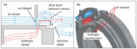
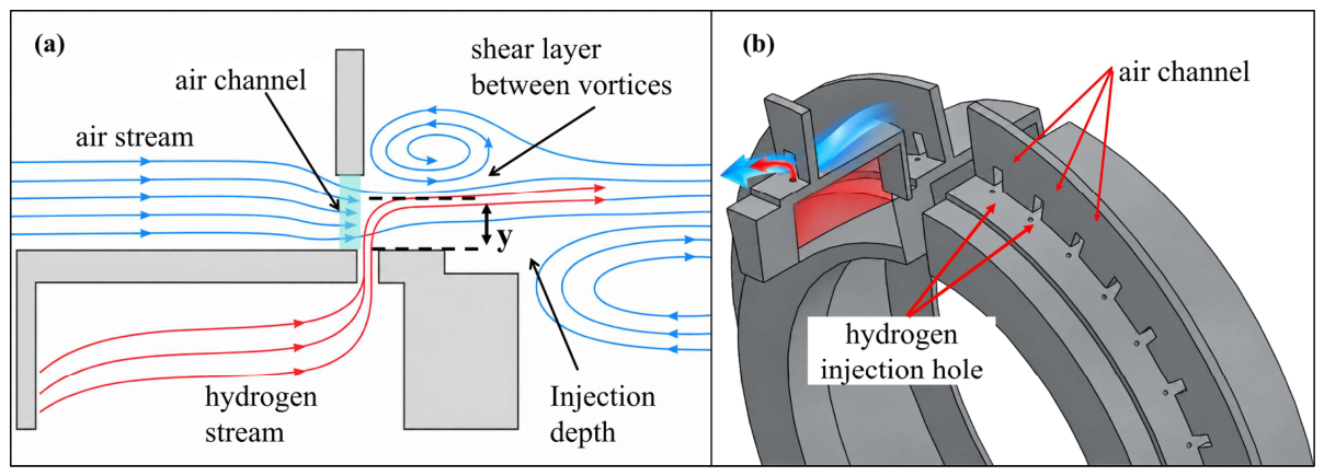
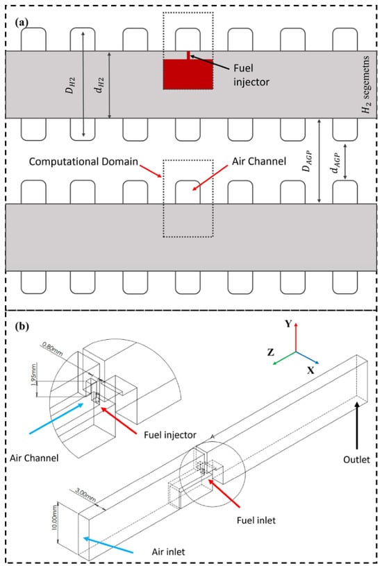
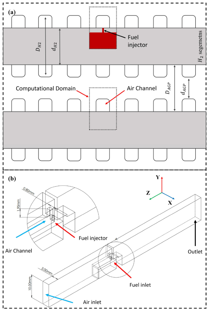
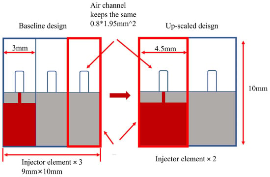
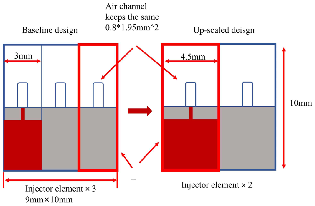
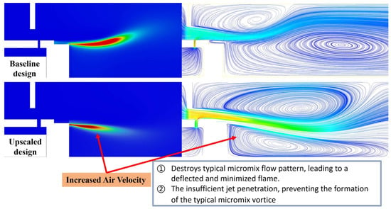
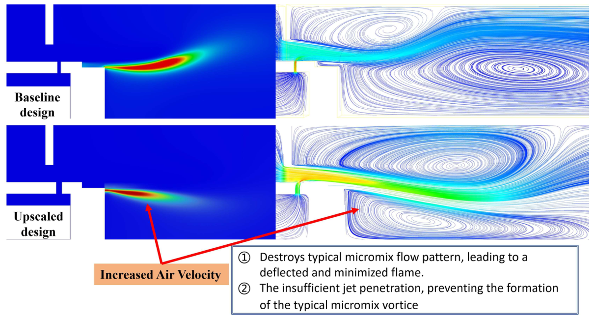
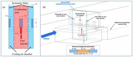
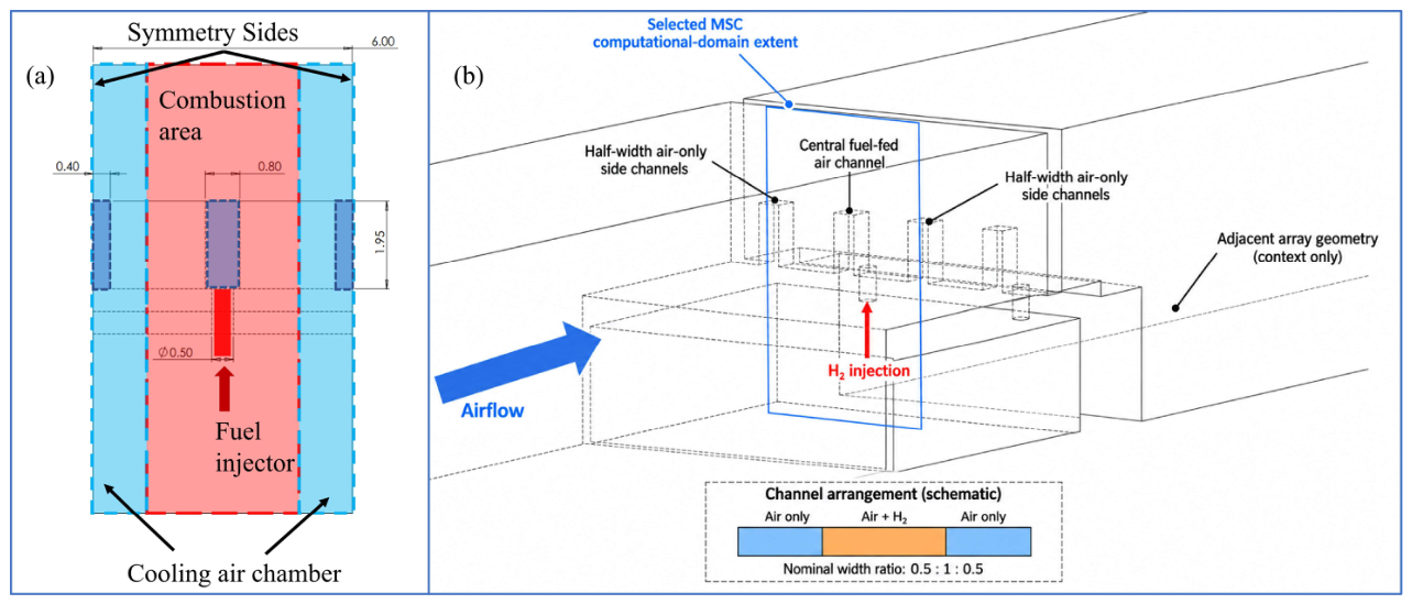
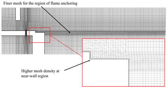
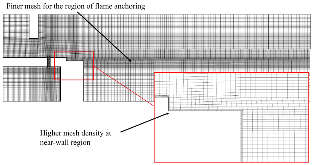
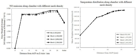
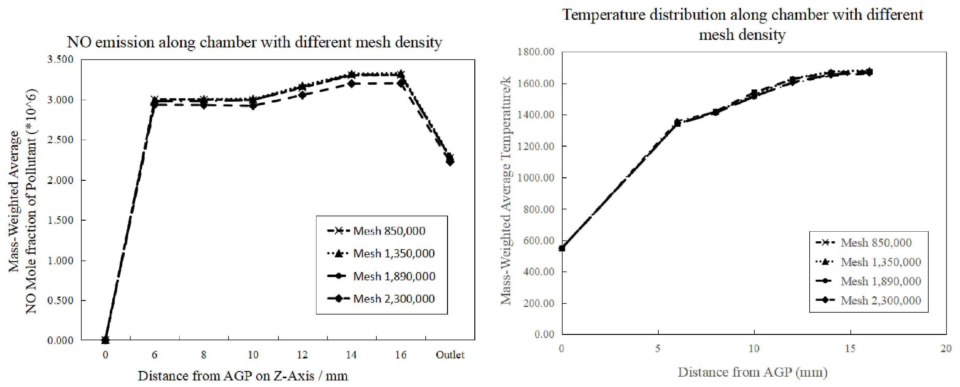
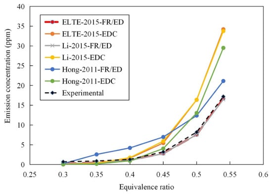
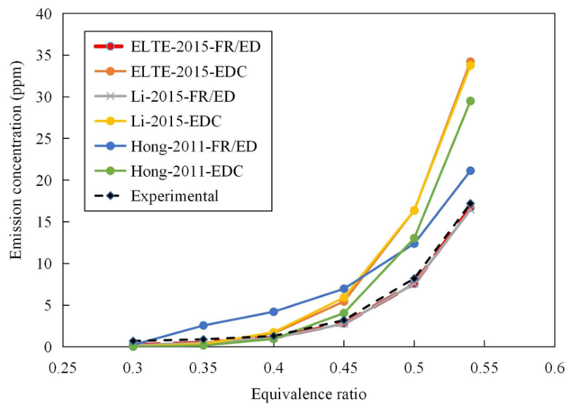
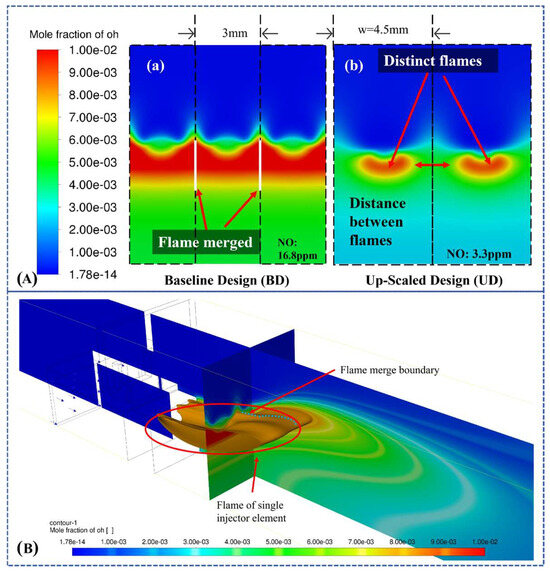
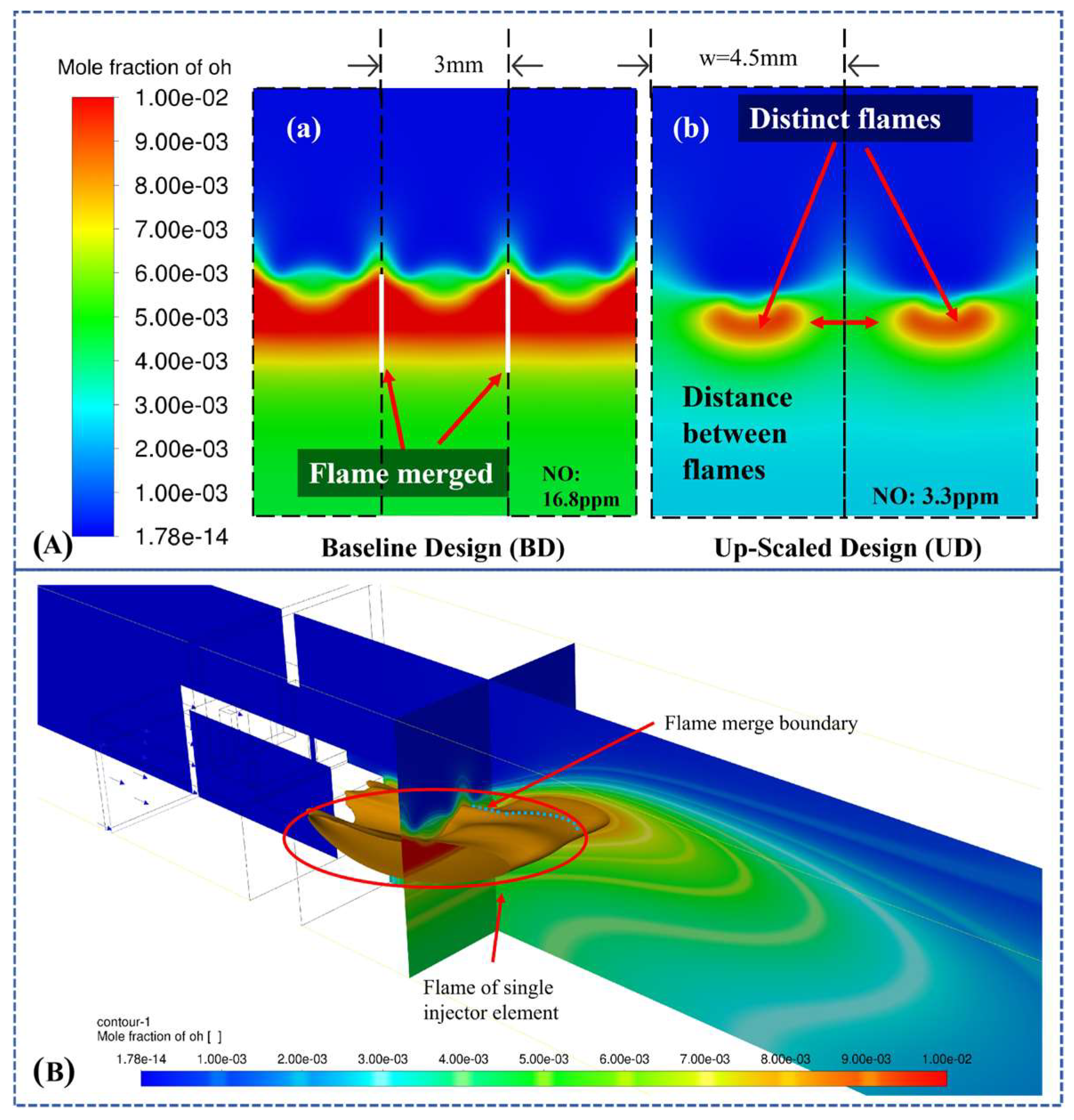
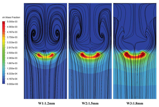
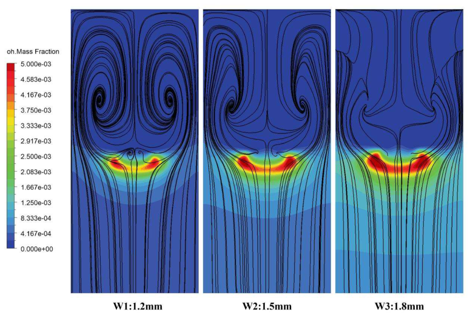
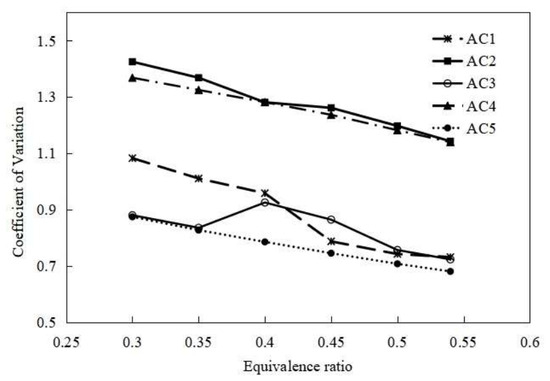
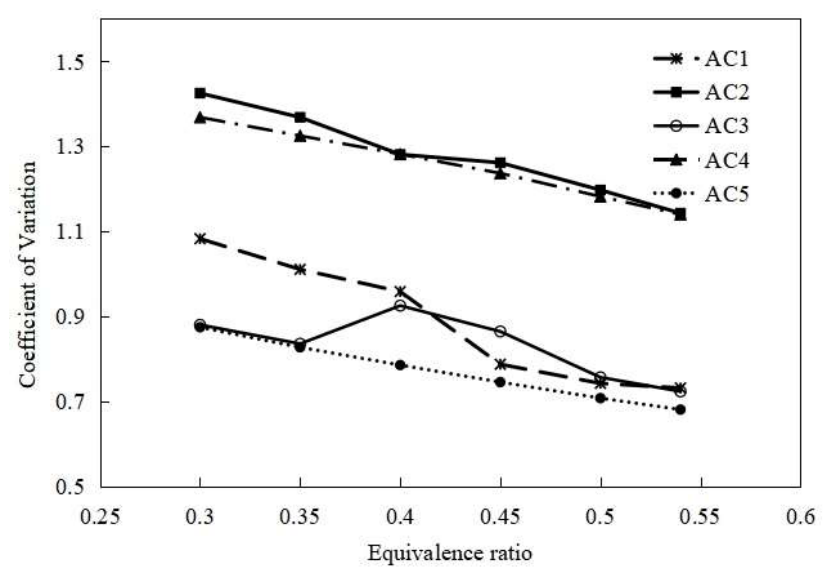
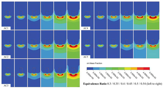
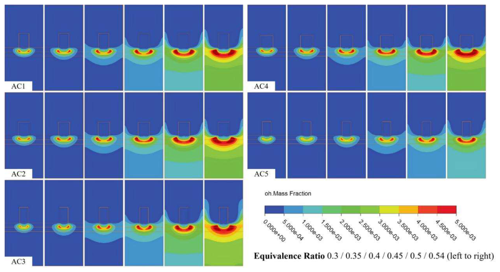
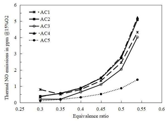
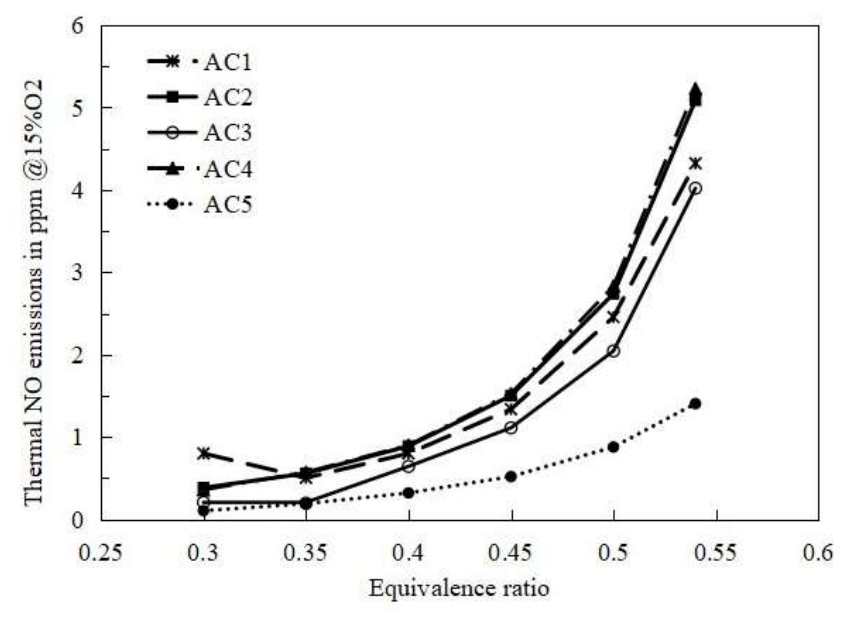
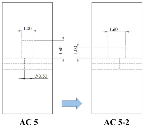
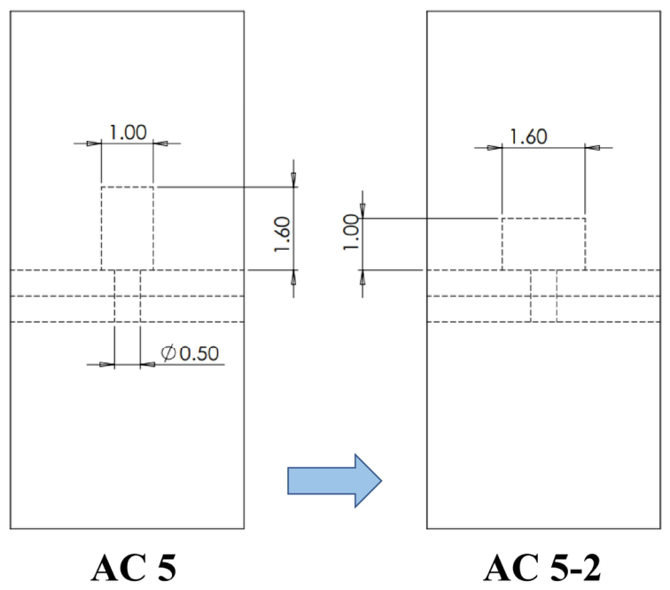
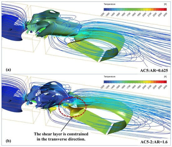
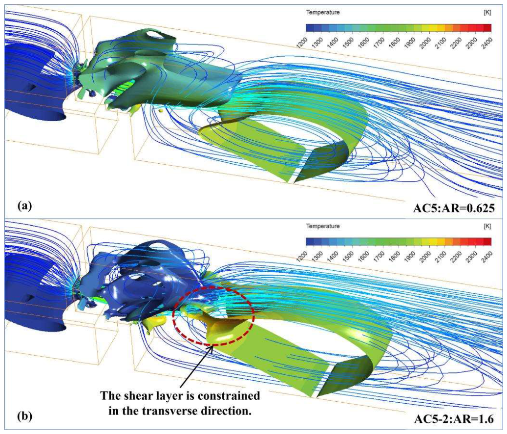
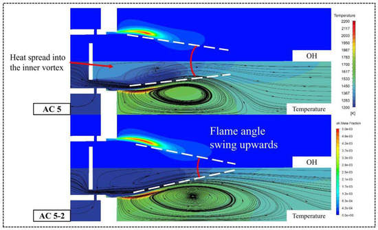
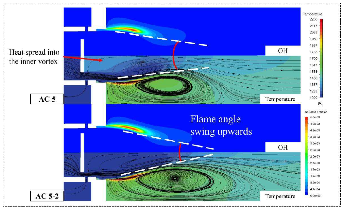
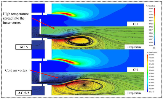
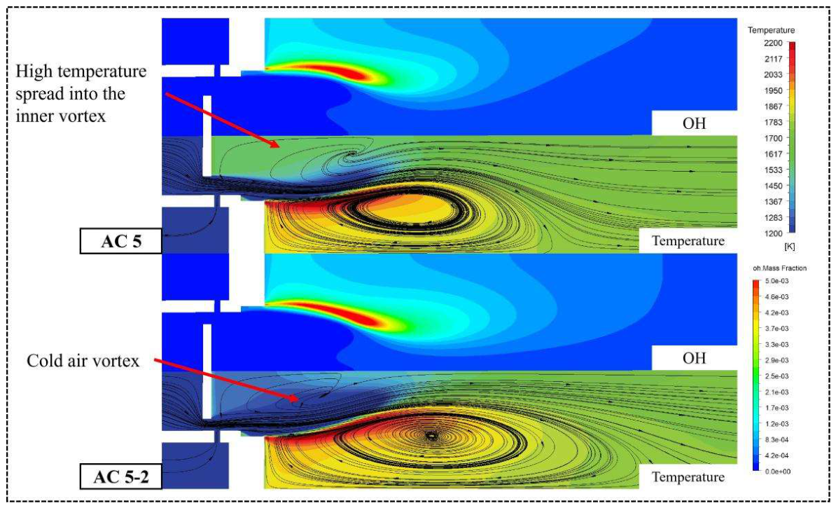
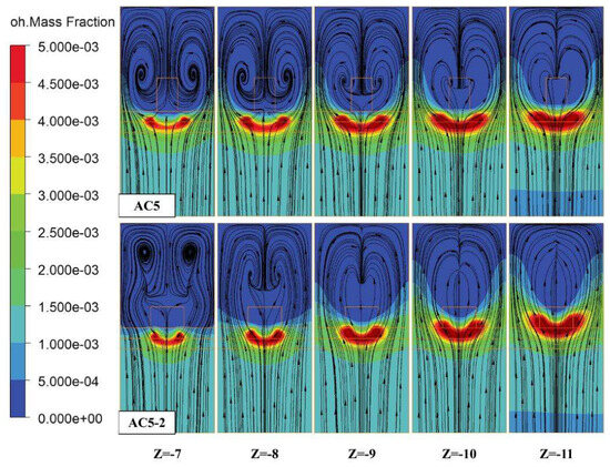
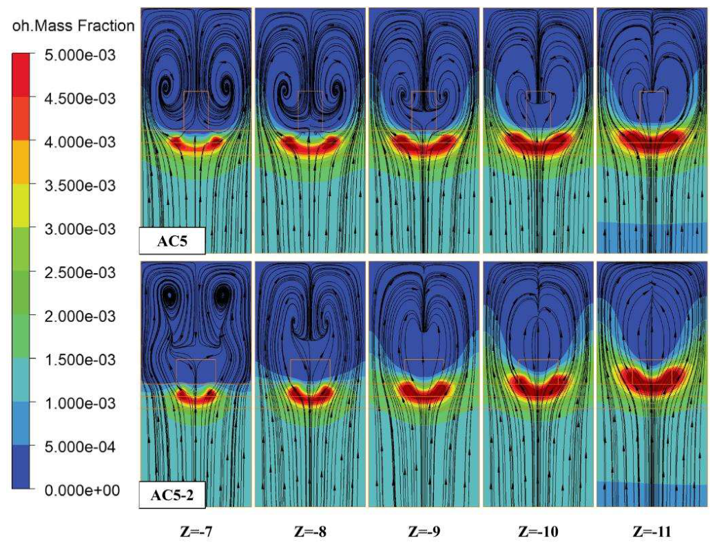
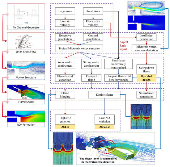
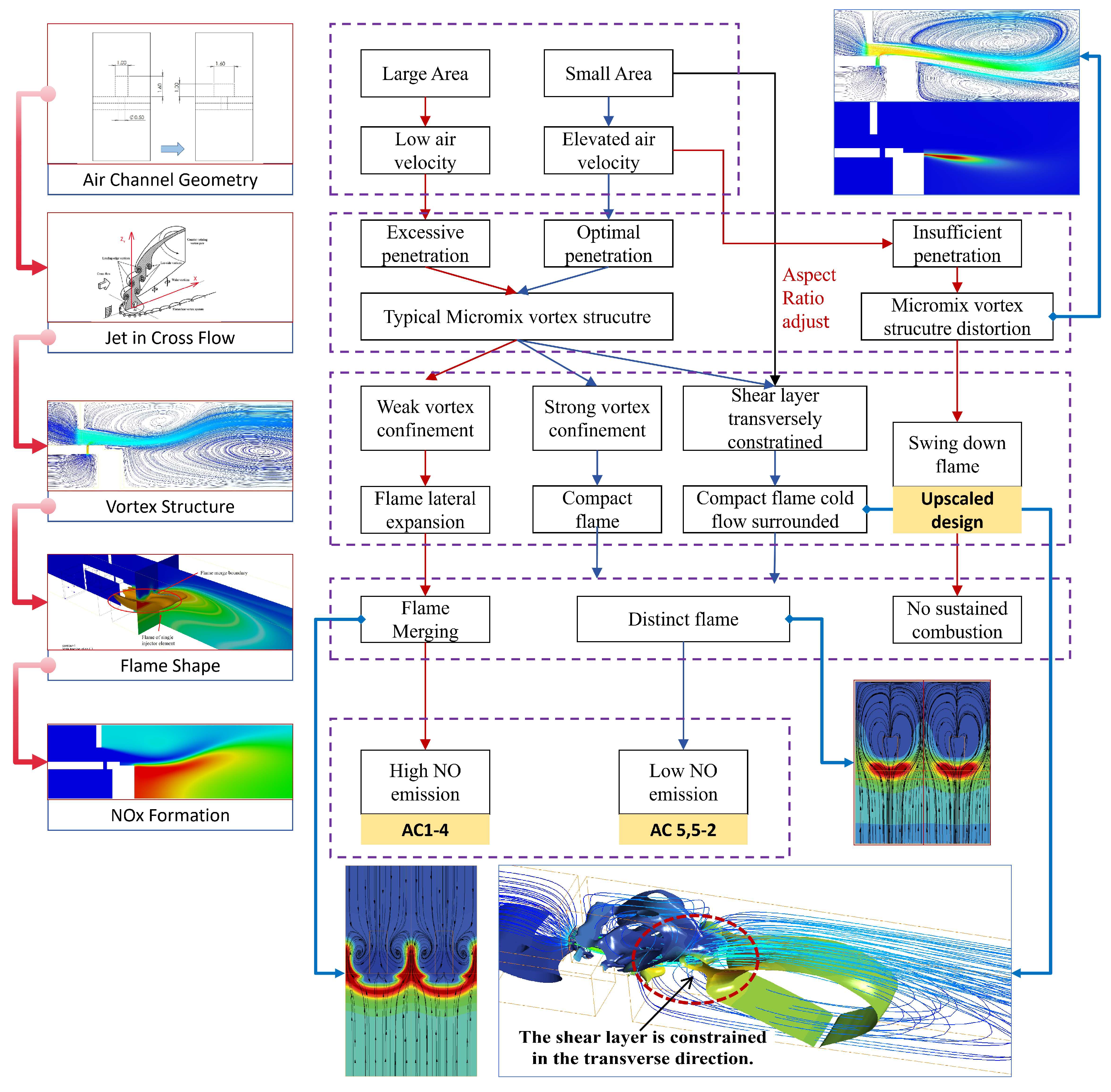
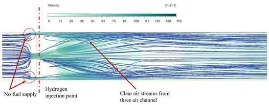
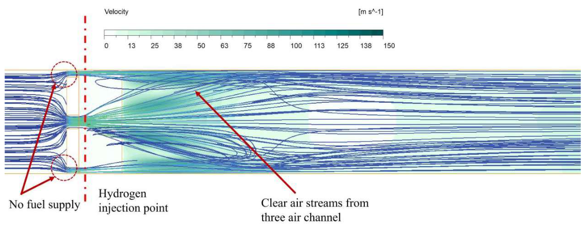
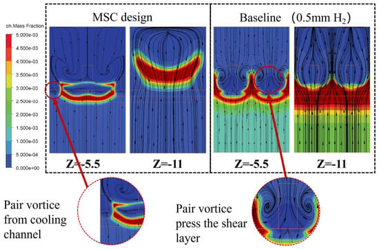
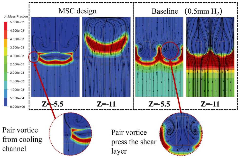
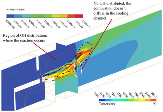
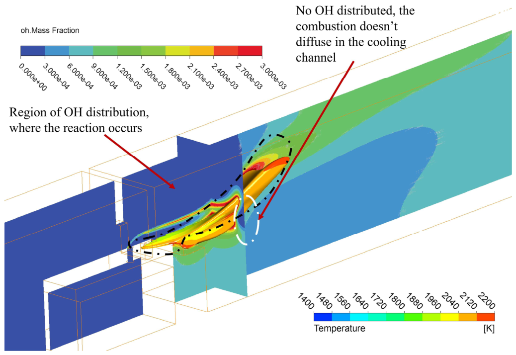
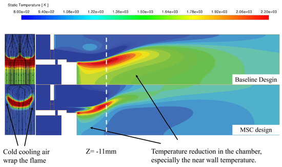
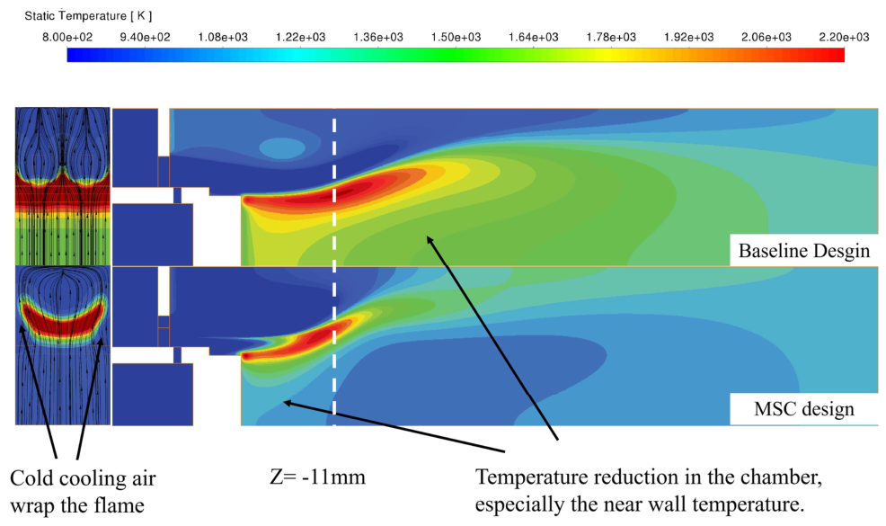
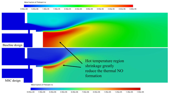
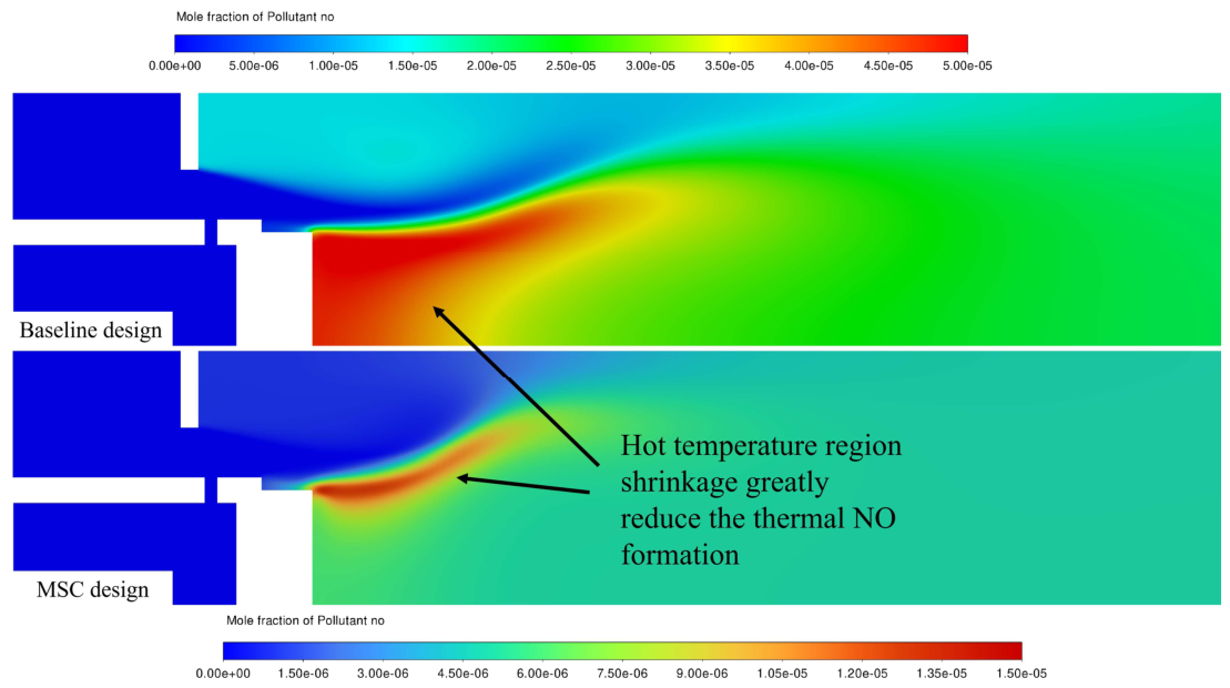

Disclaimer/Publisher’s Note: The statements, opinions and data contained in all publications are solely those of the individual author(s) and contributor(s) and not of MDPI and/or the editor(s). MDPI and/or the editor(s) disclaim responsibility for any injury to people or property resulting from any ideas, methods, instructions or products referred to in the content. |
© 2026 by the authors. Licensee MDPI, Basel, Switzerland. This article is an open access article distributed under the terms and conditions of the Creative Commons Attribution (CC BY) license.