


Abstract
Wing icing poses a significant challenge to the safe operation of battery-powered low-altitude aircraft, while conventional electrothermal deicing is constrained by its high electrical power demand. This study investigates a thermoelectric heat pump (TEHP) deicing method that combines Peltier heat pumping with Joule heating to improve deicing energy efficiency. A multiphysics numerical framework coupling icing, fluid flow, electrical conduction, and heat transfer is developed in ANSYS Fluent using Fluent Icing, the Electric Potential module, and user-defined wall heat-flux expressions. Under the investigated representative icing condition and equal electrical power input, the unit-level COP of TEHP deicing is 3.479–5.88% higher than that of conventional electrothermal deicing under stagnant internal-air conditions. With a 5 m/s internal airflow, the COP improvement increases to 15.7–37.69%. At an input current of 1.5 A, increasing the internal airflow velocity from 2.5 to 7.5 m/s improves the TEHP COP by 12.33–19.86% relative to the stagnant condition. These results demonstrate the feasibility of TEHP deicing and highlight the beneficial role of internal-air heat absorption in improving deicing energy efficiency.
1. Introduction
Advances in unmanned aerial vehicles (UAVs) and electric vertical take-off and landing (eVTOL) aircraft are accelerating the electrification of low-altitude aviation. As these aircraft are increasingly deployed in complex low-altitude environments, they are frequently exposed to adverse weather conditions, including low clouds, rain, snow, and mixed-phase precipitation. In particular, low-altitude atmospheric conditions near the freezing point can favor the presence of supercooled water droplets and rapidly changing hydrometeor phases, increasing the likelihood of ice accretion on aerodynamic surfaces. Encounters with supercooled droplets can lead to rapid ice formation on the wing leading edge, significantly degrading aerodynamic performance and posing a serious threat to flight safety. Effective ice-protection systems are therefore essential for the safe and reliable operation of low-altitude aircraft [1,2].
Ice accretion on the wing leading edge distorts the airfoil profile, reduces lift, increases drag, and may ultimately lead to premature flow separation or stall [3,4]. Common ice-protection technologies include electrothermal, hot-air, mechanical, and chemical methods [5,6]. Hot-air systems based on engine bleed air are well established in conventional gas-turbine-powered aircraft, but are generally unsuitable for electric aircraft without an available high-temperature air source. Electrothermal systems, by contrast, are readily integrated into electrically powered platforms and have therefore become one of the most practical ice-protection options for low-altitude electric aircraft. However, conventional electrothermal systems rely on direct conversion of electrical energy into heat and consequently require substantial electrical power. This high power demand places an additional burden on the limited onboard energy storage of electric aircraft, thereby reducing their flight endurance and operational range [7].
Conventional electrothermal ice-protection systems rely primarily on resistive heating elements. The heating COP of an ideal resistance heater is unity, whereas the practical system-level COP is generally below unity because of heat losses. Therefore, although the optimization of power distribution and control strategies can reduce energy consumption, it cannot overcome the inherent efficiency limit of direct resistive heating. To address these limitations, researchers have investigated aircraft ice protection from multiple perspectives, including the optimization of electrothermal heating strategies and the development of alternative low-energy ice-removal mechanisms. Wang et al. [8] developed and validated an optimization method combining a genetic algorithm with the apparent heat-capacity method to simulate ice–water phase change and minimize ice melting and shedding time through optimized power distribution. Guo et al. [9] incorporated photothermal carbon nanofibers into an amphiphilic PDMS–PVP material to develop a sunlight-responsive icephobic coating with reduced ice adhesion and rapid photothermal deicing capability. Ma et al. [10] developed a cohesive-zone-based numerical model for electro-impulse deicing of a wing leading edge and examined the effects of ice–skin interfacial shear strength, actuator location, and pulse sequence on deicing performance.
Thermoelectric devices are solid-state heat-pumping components based on the Peltier effect. When the heat-absorbing side of a thermoelectric device is used, the device operates as a thermoelectric cooler (TEC); when the heat-releasing side is used, it functions as a thermoelectric heat pump (TEHP). TEHPs provide heating through the combined effects of Peltier heat pumping and Joule heating [11]. Therefore, compared with conventional electrothermal deicing technologies that rely solely on Joule heating, TEHP-based wing deicing can achieve considerably higher heating efficiency. In addition, TEHP systems are increasingly being developed toward thin-film configurations [12]. Owing to their solid-state structure, compactness, rapid response, and high reliability [13], TEHPs can not only meet deicing requirements but also contribute to the thermal management of onboard electronic equipment, thereby enabling integrated energy utilization [14]. This capability is of significant engineering value for low-altitude electric aircraft that rely exclusively on batteries as their energy source. In recent years, extensive research has been conducted to improve the performance of thermoelectric devices, with particular attention paid to thermoelectric material properties, multistage topological designs, and multiphysics-coupled thermal management applications in various fields. Corbett et al. [15] investigated an electrodeposited thin-film thermoelectric cooler and achieved a heat flux of 720 ± 60 W/cm2 at room temperature by engineering the contact interfaces. Boudreaux et al. [16] examined the replacement of the resistance heater in a conventional clothes dryer with a TEHP and evaluated the resulting drying efficiency and drying time. Their results showed that the efficiency of the TEHP dryer was 40% higher than that of the conventional dryer. These studies indicate that, under an appropriate temperature difference between the hot and cold sides, thin-film TEHPs can pump external thermal energy from the cold side to the hot side with relatively low electrical energy consumption, thereby achieving a heating COP far higher than that of conventional Joule heating. This makes thermoelectric technology a promising approach for overcoming the energy-efficiency limitations of aviation electrothermal systems.
Despite these advances, existing aircraft ice-protection studies have focused predominantly on conventional electrothermal heating and other low-energy deicing mechanisms, whereas current thermoelectric research has mainly addressed cooling, thermal management, and heating applications outside aircraft icing environments. Consequently, the application of thin-film TEHPs to aircraft wing deicing remains insufficiently investigated, particularly regarding the coupled interactions among icing, external and internal airflow, electrical conduction, and thermoelectric heat transfer. In addition, the influence of internal-air heat absorption on TEHP deicing performance and energy efficiency has not been systematically clarified under representative icing conditions.
Against this background, this study investigates the feasibility and fundamental performance of thin-film TEHP technology for wing deicing of low-altitude electric aircraft. The main contributions of this work are as follows:
- (1)
- A multiphysics numerical framework coupling icing, fluid flow, electrical conduction, and heat transfer is established to describe the interaction between wing icing and TEHP heating;
- (2)
- An airfoil-scale model is employed to evaluate the spatial icing characteristics, wing-surface thermal response, and deicing effectiveness under a representative low-altitude icing condition, while a detailed TEHP unit model is used to characterize the unit-level thermoelectric performance;
- (3)
- The effects of input current and internal airflow on the heat absorption, temperature response, and unit-level COP of the TEHP are quantified, thereby clarifying the role of internal forced convection in improving TEHP deicing energy efficiency. These results provide a basis for further optimization of TEHP configurations, operating strategies, and integrated thermal-management schemes for low-altitude electric aircraft.
2. Physical Model and Calculation Principles
2.1. Working Principle
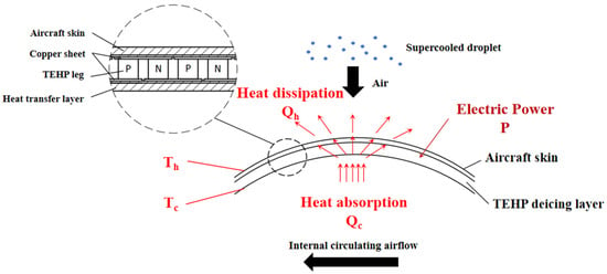
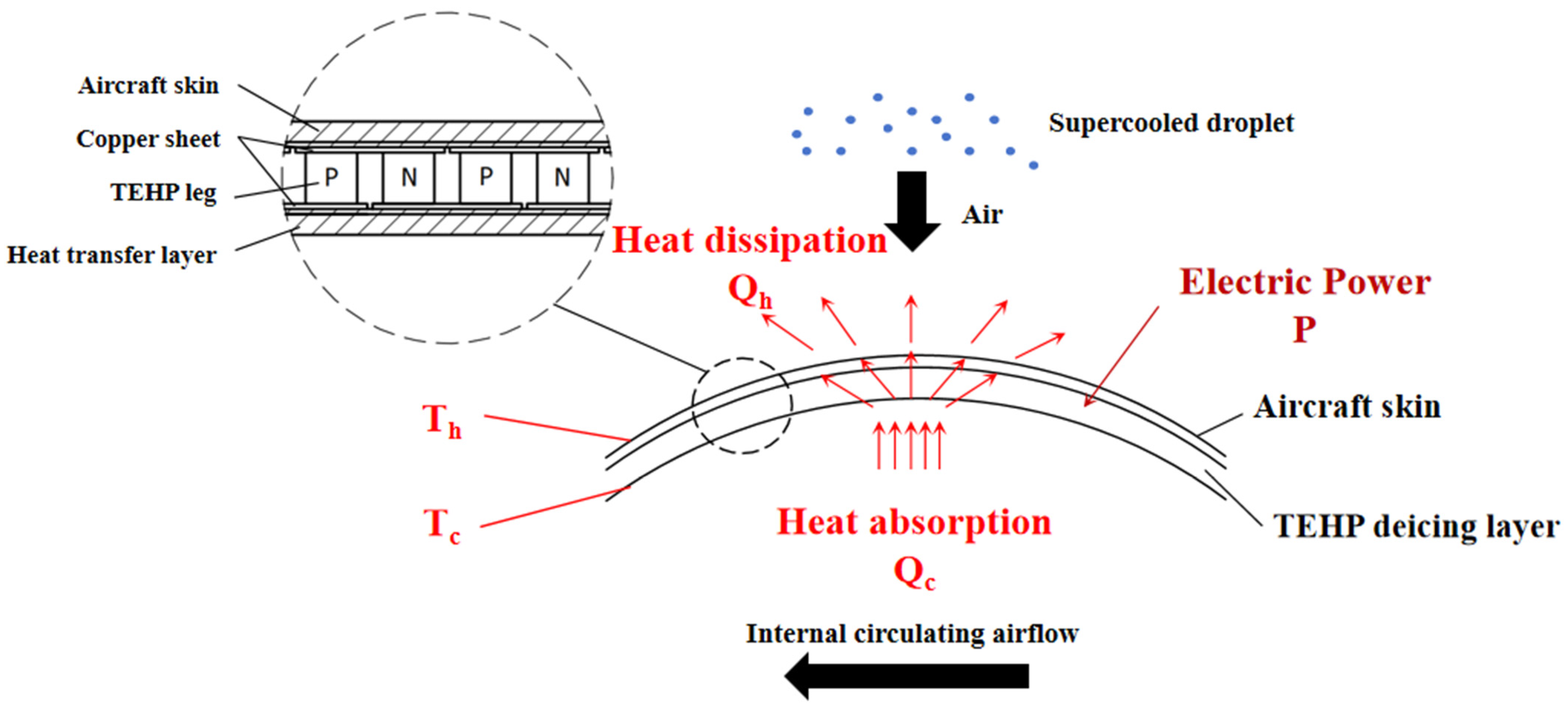
Figure 1 schematically illustrates the proposed thermoelectric heat pump (TEHP) deicing system and the enlarged structure of the TEHP thin-film layer. The TEHP deicing layer is integrated with the aircraft skin and thermally coupled to it through a heat-transfer layer. As shown in the inset, each TEHP unit consists of alternately arranged P- and N-type thermoelectric legs sandwiched between copper electrodes, forming a compact thin-film heat-pumping structure. When a direct current is applied, the Peltier effect establishes a hot side and a cold side across the thermoelectric legs, while Joule heating generated within the legs also contributes to the heat released at the hot side. In the proposed configuration, the heat-releasing side faces the aircraft skin and supplies heat to the wing surface for deicing, while the heat-absorbing side is coupled to an internal circulating airflow within the wing. This airflow is conceived as part of the aircraft’s internal thermal-management loop rather than as air introduced directly from the external icing environment. In an integrated thermal-management system, the circulating air may absorb waste heat from onboard components, including batteries and electrical equipment, before transferring this thermal energy to the TEHP heat-absorbing side. The absorbed heat is subsequently pumped toward the aircraft skin, allowing the TEHP to provide localized deicing while potentially contributing to the coordinated utilization of onboard waste heat.
Figure 1.
Schematic of the physical model of the thermoelectric heat pump deicing system.
2.2. Mathematical Model
To represent the above thermoelectric deicing processes within a tractable numerical framework while retaining the dominant physical mechanisms, the following idealized assumptions are adopted in the numerical model of the TEHP deicing system:
- (1)
- Perfect thermal and electrical contact is assumed between adjacent solid components, and thermal and electrical contact resistances are neglected.
- (2)
- The thermoelectric properties of the semiconductor materials are treated as constant within the investigated temperature range.
- (3)
- The internal circulating air is treated as dry single-phase air, and moisture transport and frost formation on the TEHP heat-absorbing surface are neglected.
2.2.1. Droplet, Water-Film, and Icing Model
The icing process involves the transport and impingement of supercooled droplets, the migration of the surface water film, and the associated freezing and melting processes. These processes were modeled using Fluent Icing. Under the steady-state droplet-flow condition adopted in the present study, the conservation and momentum equations of the droplet phase are expressed as:
where α is the droplet volume fraction; Va and Vd are the velocities of the air and droplets, respectively; ρa and ρd are the densities of the air and droplets, respectively; Cd is the drag coefficient; and the droplet Reynolds number Red, inertia parameter K, and Froude number Fr are defined as follows:
The resulting droplet velocity and concentration fields determine the droplet impingement distribution on the wing surface. After impingement, the unfrozen liquid water forms a thin water film and migrates along the surface under the action of aerodynamic shear. The mean water-film velocity is given by:
where τa,wall is the air wall shear stress on the liquid film, μf is the dynamic viscosity of the water film, and hf is the water film thickness.
The local icing and melting processes are determined by the energy balance of the surface water film and ice. Considering the energy contributions associated with droplet impingement, convection, evaporation, radiation, sensible heat, latent heat of phase change, and the heat supplied by the deicing system, the surface energy equation is expressed as:
where ρf and cf are the density and specific heat of water, respectively; LWC is the liquid water content of the air; mevap and Levap are the evaporation mass flow rate and latent heat of vaporization of the droplets, respectively; Tice and cice are the thermodynamic temperature and specific heat of ice, respectively; Lfus is the latent heat of fusion; and σ and ε are the Stefan-Boltzmann constant and emissivity, respectively; β is droplet collection efficiency, defined as follows:
2.2.2. Thermal Coupling Model of the Thermoelectric Heat Pump
For a single semiconductor thermoelectric leg, the heat transfer on either side is expressed as:
where Qh and Qc represent the heat released at the heat-releasing side and the heat absorbed at the heat-absorbing side, respectively; Qph and Qpc are the corresponding Peltier heats on both sides; Qjh and Qjc are the corresponding Joule heat on both sides; Qλ is the heat conduction within the thermoelectric leg.
Qh = Qph + Qjh − Qλ
Qc = Qpc − Qjc − Qλ
Qj = Qjh + Qjc = I2R
The Peltier heat is given by:
where S is the Seebeck coefficient, V/K; I is the current intensity passing through the thermoelectric leg, A; and T is the thermodynamic temperature of the heat-exchanging side of the thermoelectric leg, K.
Qp = SIT
Thus, we have:
where Th and Tc are the thermodynamic temperatures of the heat-releasing side and heat-absorbing side of the thermoelectric leg, K, respectively; λ is the thermal conductivity of the thermoelectric leg material, W/(m·K); A is the cross-sectional area of the thermoelectric leg, m2; and l is the length of the thermoelectric leg, m.
Based on the conservation of energy, the energy consumption of the thermoelectric leg is:
P = Qh − Qc = SI(Th − Tc) + I2R
In this study, the deicing coefficient of performance (COP) is defined as the ratio of the useful heat transferred to the wing skin to the electrical power input of the deicing system. For the TEHP cases with forced internal airflow, the electrical power consumption of the circulation fan, Qfan, is also included in the total power input when evaluating the deicing COP. During transient operation, the heat delivered to the wing skin may differ from the total heat released by the hot side of the TEHP because of thermal energy storage and heat losses within the coupled structure. Under steady-state conditions, however, the TEHP hot side is directly thermally coupled to the wing skin, and the net thermal energy storage in the intermediate layers becomes negligible. Therefore, the heat transferred to the wing skin can be approximated by the heat-rejection rate of the TEHP hot side, Qh. Accordingly, the deicing COP under steady-state conditions can be expressed as follows:
where Pfan is the electrical power consumption of the circulation fan, W; Δp is the pressure rise provided by the fan, which corresponds to the pressure loss of the internal airflow passage, Pa; qair is the volumetric flow rate of the internal circulating air, m3/s; and ηfan is the fan efficiency.
When using only Joule heat for deicing, the heat transfer on either side is expressed as follows:
where Qj1 and Qj2 are the heat transfer rates of the thermoelectric leg at the aircraft skin side and the internal side, W, respectively; T1 and T2 are the thermodynamic temperatures of the thermoelectric leg at the aircraft skin side and the internal side, K, respectively.
3. Calculation Methodology for Thermoelectric Heat Pump Deicing
3.1. Geometric Model and Boundary Conditions
The present study focuses on deicing. In other words, the removal of ice after ice accretion has occurred. Anti-icing operation, in which the TEHP is activated before ice formation to prevent ice accretion, is not specifically investigated in the present study. To evaluate the feasibility of the proposed thermoelectric heat pump deicing system, a multiphysics numerical framework coupling icing, fluid flow, electrical conduction, and heat transfer was established in ANSYS Fluent 2025 R2. In this framework, Fluent Icing was used to simulate droplet impingement and ice accretion on the wing surface, while the Electric Potential module was employed to calculate electrical conduction and Joule heating within the thermoelectric elements. The Peltier heat was incorporated into the thermal model through user-defined wall heat-flux expressions according to Equation (12). A unit-cell model was first developed to analyze the heat-pumping performance of the TEHP, and simulations of a complete airfoil model were subsequently conducted to assess the deicing performance of the proposed system under airfoil-scale icing conditions.
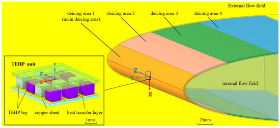
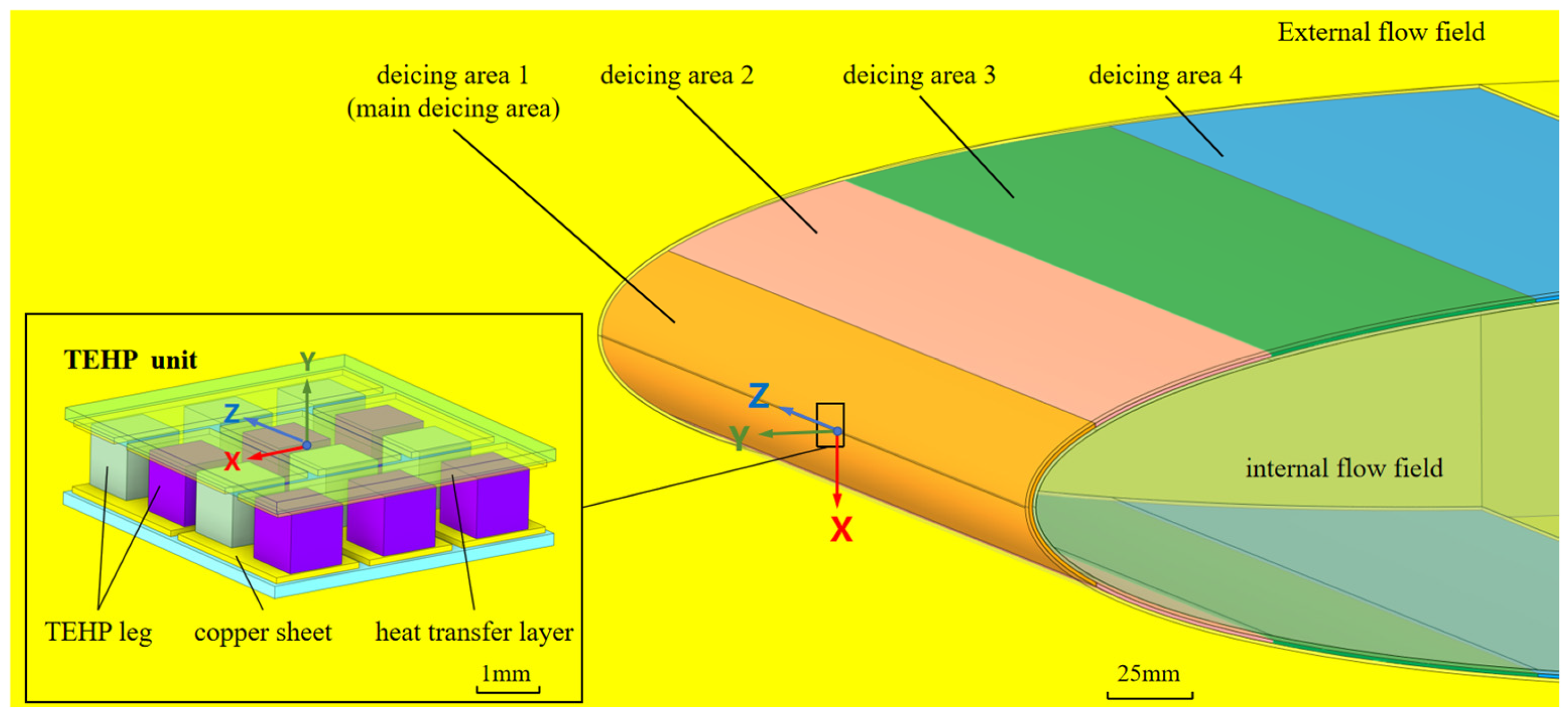
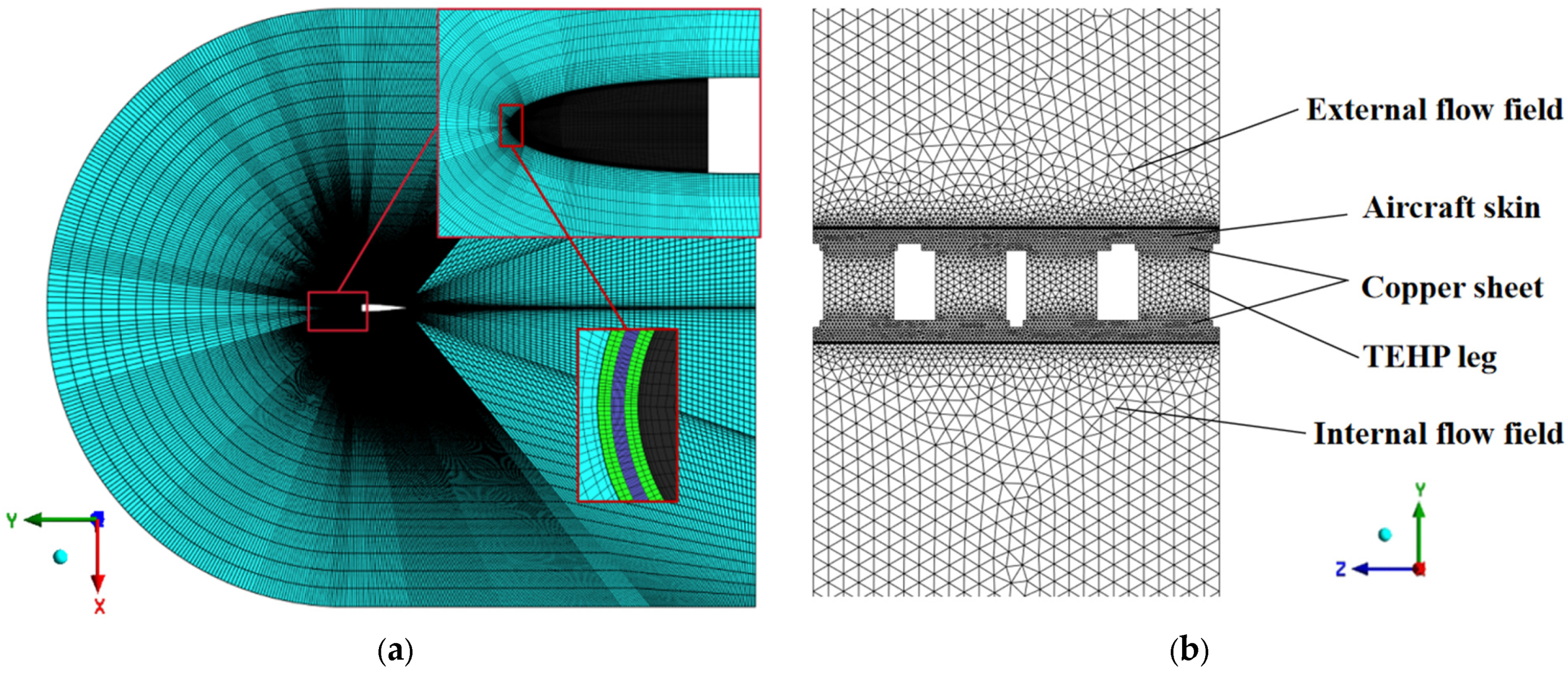
Airfoil-scale simulations of the proposed TEHP deicing system were performed using a NACA0012 airfoil with a chord length of 0.48 m and the total computational-domain depth in the spanwise direction of 428.8 mm. Figure 2 shows the integrated geometric model, including the external flow field, the internal circulating airflow region, the zoned deicing areas on the wing leading edge, and an enlarged view of the TEHP unit. The coordinate origin O is located at the wing leading edge. The x-axis is oriented along the chordwise direction, while the z-axis corresponds to the spanwise direction. Accordingly, x = 0 denotes the cross-section passing through the wing leading edge. The corresponding computational mesh is presented in Figure 3, where the global airfoil mesh and the local cross-sectional mesh of the TEHP-coupled skin structure are shown together to illustrate the coupling among the external flow field, aircraft skin, TEHP layer, and internal airflow. Two computational models were established for different computing requirements. The airfoil-scale model was used to simulate the external airflow, droplet impingement, ice accretion, and overall deicing performance of the wing. A structured mesh with local refinement near the wing surface was adopted to accurately resolve the aerodynamic and icing-related boundary layers.
Figure 2.
Geometric model of the internal–external flow coupling domain and enlarged view of the TEHP unit structure.
Figure 3.
Computational meshes used in the present study: (a) structured mesh of the airfoil-scale deicing model; (b) unstructured mesh of the detailed TEHP unit-cell model.
In addition, a detailed TEHP unit-cell model was developed to resolve the local electrical-thermal-fluid coupling among the thermoelectric legs, copper electrodes, wing skin, and internal airflow. Owing to the complex multi-material geometry of the TEHP unit, an unstructured mesh was employed in this model. The different meshing strategies were therefore selected according to the geometric and physical characteristics of the two computational models.
The TEHP unit consists of a 3 × 4 array of alternately arranged P- and N-type thermoelectric legs connected by copper sheets. Each thermoelectric leg has dimensions of 1 mm × 1 mm × 1 mm, resulting in a total heat-transfer area of 31.32 mm2 for a single unit. In practical deployment, adjacent TEHP units are closely tiled along both the chordwise (x) and spanwise (z) directions of the wing skin, forming a continuous and compact deicing layer. Similar to conventional electrothermal deicing heaters, the proposed TEHP layer is intended to operate within the wing structure rather than being mounted as an external protruding component. Therefore, its installation does not directly alter the external aerodynamic profile of the wing, although sufficient internal space must be reserved for the thermoelectric layer, electrodes, wiring, bonding materials, and airflow passage. The TEHP layer is integrated into the wing-skin structure through a heat-transfer layer. Based on the structural characteristics and surface coverage of the TEHP units, the thermal conductivity, electrical conductivity, and packing density of the thermoelectric legs are homogenized into an equivalent single-layer thermoelectric deicing material. According to the deicing heat-load distribution over the wing surface, the deicing region is divided into four zones, with the wing leading edge designated as the primary deicing region. The thermoelectric legs are made of commercially available Bi2Te3-based semiconductor materials, and their principal thermoelectric properties are summarized in Table 1. Based on the material density, geometric dimensions, and packing density of the thermoelectric elements, the designed TEHP layer has an areal mass density of approximately 16.551 kg/m2. For the selected 0.06 m chordwise primary deicing region, this corresponds to approximately 0.993 kg of TEHP material per meter of wing span. Although this additional mass is introduced in exchange for improved deicing energy efficiency, it also imposes an additional constraint on lightweight wing design and should therefore be considered together with the structural load and mass allocation of the aircraft.
Table 1.
Physical properties of bismuth telluride-based semiconductor materials.
The simulation model enables two-way coupling among the external supercooled-droplet flow, the aircraft skin, and the internal circulating airflow. Pressure-far-field boundary conditions are imposed on the external flow domain, and the outer surface of the wing skin is coupled with the droplet impingement, ice accretion, and convective heat-transfer processes. On the inner side of the wing skin, an internal circulating airflow is introduced along the cold side of the TEHP layer. This airflow serves as the heat source for the cold side and enhances convective heat transfer, thereby allowing the absorbed heat to be continuously pumped toward the aircraft skin and maintaining stable operation of the TEHP deicing system.
In the present model, the internal circulating airflow is treated as a single-phase dry-air flow that is isolated from the external icing airflow by the wing skin and TEHP structure. Therefore, moisture transport from the external icing environment into the internal airflow passage is not considered. The cold-side convective heat transfer is directly resolved through the conjugate fluid–solid calculation, and the corresponding heat-transfer coefficient varies with airflow velocity, local temperature, fluid properties, and geometry.
In an actual aircraft installation, if moisture is present in the internal circulating air and the TEHP cold-side temperature falls below the frost-point temperature, frost may form on the cold-side surface. The resulting frost layer would introduce an additional thermal resistance and reduce the heat absorption rate of the TEHP. Frost formation on the internal side is beyond the scope of the present dry-air model and should be considered in future system-level studies involving humidity control and long-duration operation.
3.2. Multiphysics Coupling Procedure
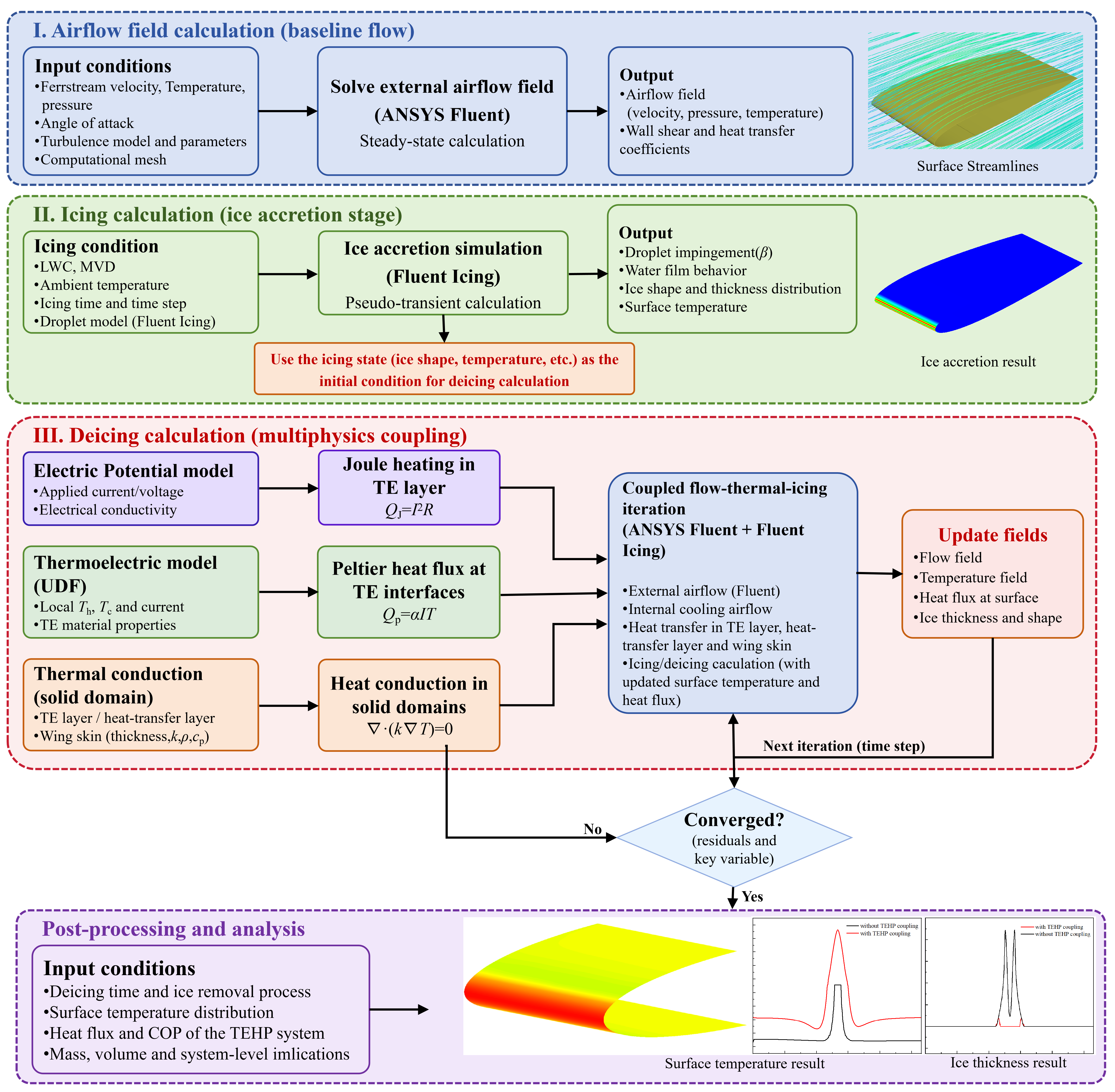
The process of numerical calculation is shown in Figure 4. First, the external airflow field is solved under the prescribed icing conditions, after which Fluent Icing is used to calculate supercooled-droplet impingement, wall-water-film behavior, and the resulting ice accretion on the wing surface. The obtained icing state is then used as the initial condition for the deicing calculation.
Figure 4.
The process of numerical calculation.
In the deicing stage, the Electric Potential model is activated to calculate the electrical field and Joule heating within the thermoelectric layer. Meanwhile, the Peltier heat at the heat-releasing and heat-absorbing sides is introduced through user-defined wall heat-flux expressions based on the local interface temperatures and applied current. The flow and energy equations are then solved iteratively with thermal coupling among the TEHP layer, heat-transfer layer, wing skin, external airflow, and internal airflow. Heat conduction within the wing skin is directly resolved through the solid-energy equation, allowing the heat released by the TEHP to spread both through the thickness and along the chordwise direction before being transferred to the external icing surface. The updated wing-surface temperature and heat flux are transferred to the icing/deicing calculation, and the thermal and icing fields are progressively updated until convergence is achieved for each calculation step. The overall coupling procedure can therefore be summarized as airflow solution, icing calculation, activation of electrical and thermal models and coupled deicing iteration.
The external airflow, droplet-impingement, icing-rate, and TEHP performance calculations used in the main analyses were solved to steady convergence; therefore, no physical time step was involved in these calculations. The transient calculation was used only for the independent validation case described in Section 3.3.2.
3.3. Grid and Model Validation
3.3.1. Grid Independence Verification
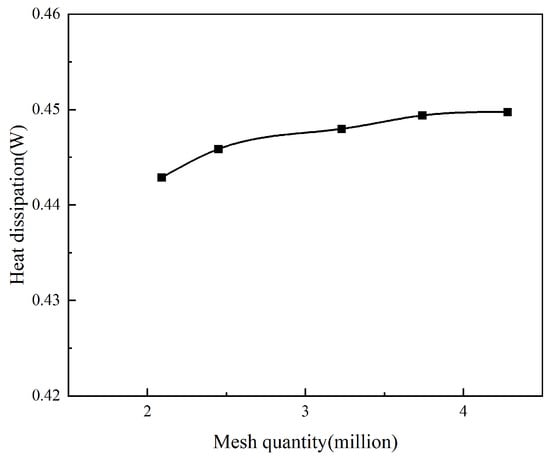
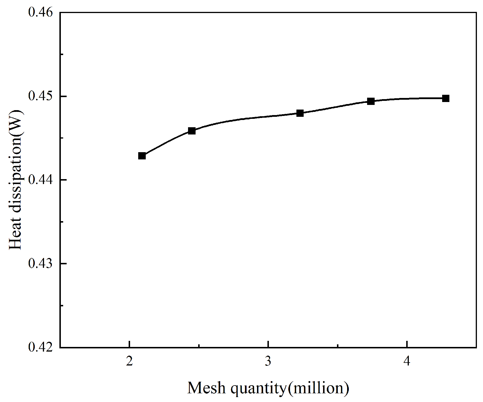
To evaluate the grid independence of the TEHP unit model, five mesh schemes with total cell numbers ranging from 2.09 million to 4.28 million were tested. The mesh was progressively refined in the regions most relevant to the thermoelectric and heat-transfer processes. Specifically, the characteristic cell size within the solid regions of the TEHP unit was gradually reduced, while the mesh adjacent to the wing skin was refined by reducing the near-wall cell size and adjusting the thickness and resolution of the boundary-layer mesh. The characteristic TEHP solid-region cell size was reduced from approximately 0.15 mm to 0.08 mm, while the near-wall mesh size was reduced from 0.02 mm to 0.01 mm as the grid was refined. The computational geometry, physical models, and boundary conditions were kept identical for all mesh schemes. All cases were calculated at an ambient temperature of 265 K, a freestream Mach number of 0.298, and an input current of 1.5 A. Grid independence was assessed using the heat output, Q, delivered by the TEHP to the wing skin. As shown in Figure 5, the predicted heat output converges when the mesh contains approximately 2.45 million cells, and further mesh refinement produces only negligible changes. Therefore, the mesh with approximately 2.45 million cells was adopted for the subsequent simulations, and the first-layer cell height normal to the wing surface on the external moist-air side was set to 0.013 mm in the mesh adopted for the subsequent calculations.
Figure 5.
Grid independence analysis.
3.3.2. Validation of the Thermoelectric Coupling Model
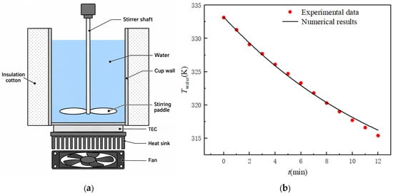
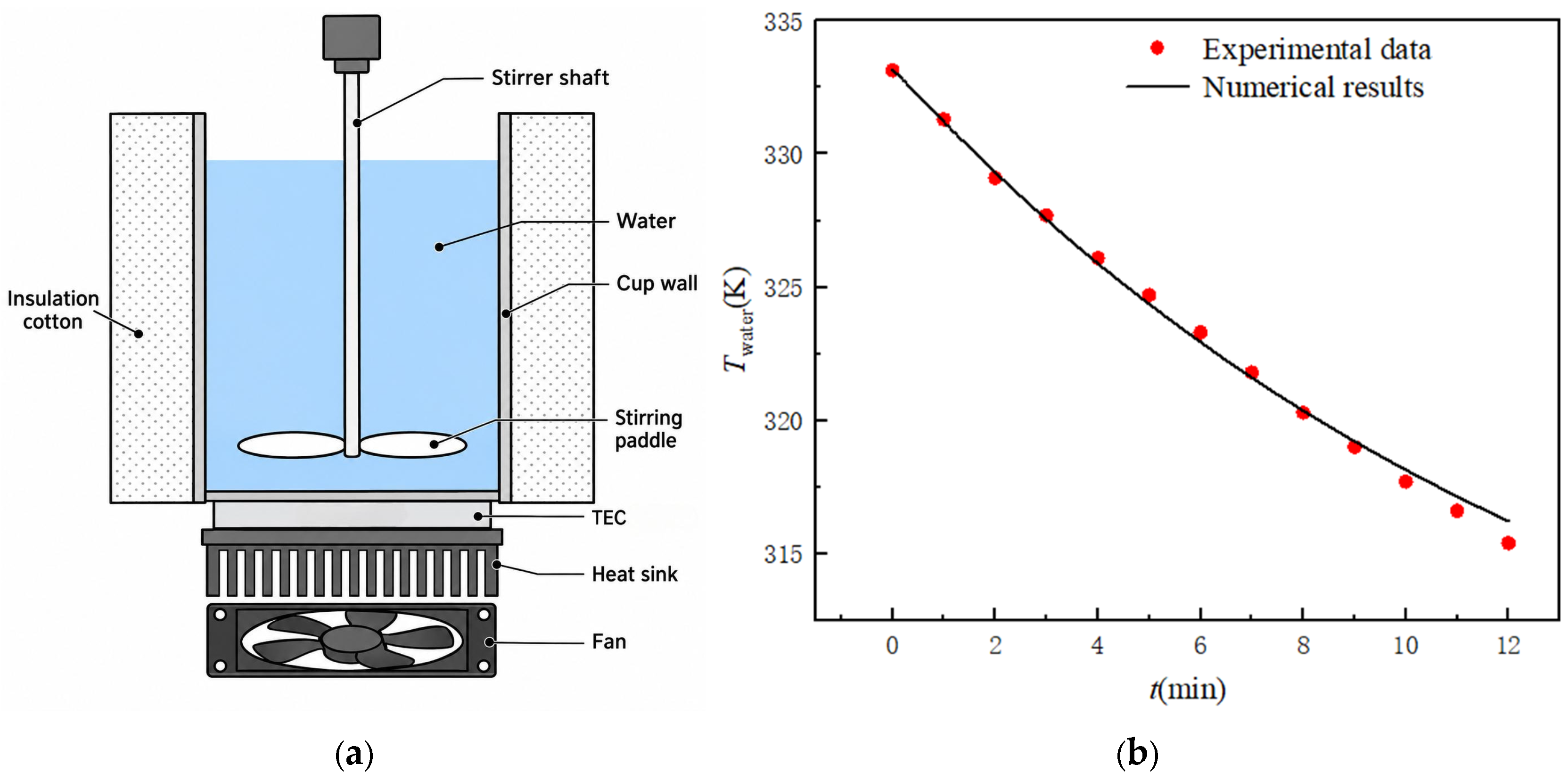
The thermoelectric electrical, thermal and fluid coupling model constitutes the principal additional physical module introduced into the present icing/deicing framework. Its reliability was therefore assessed independently against the refrigerated water-cup experiment reported in Ref. [17]. The reference experiment provides a coupled thermoelectric heat-transfer process involving electrical input, heat pumping, solid heat conduction, fluid convection, and transient thermal response, making it suitable for evaluating the thermoelectric coupling treatment adopted in the present study.
As shown schematically in Figure 6a, the experimental system consists of a thermally insulated water cup, a commercial TEC module installed beneath the cup, a heat sink with forced-air cooling, and a stirring device. Continuous stirring was employed to suppress thermal stratification in the water and to obtain a representative bulk-water temperature. Accordingly, the volume-averaged water temperature predicted by the numerical model was selected for comparison with the experimental measurements.
Figure 6.
Validation of the thermoelectric coupling model: (a) schematic of the refrigerated water-cup experimental system adapted from Ref. [17]; (b) comparison between the experimental and numerical water-temperature responses.
The validation model was reconstructed according to the geometric configuration, thermal boundary conditions, and operating conditions reported in Ref. [17]. The water-side mixing induced by the stirring paddle was reproduced numerically, and the experimentally determined equivalent convective heat-transfer coefficient was applied at the heat-dissipation side of the TEC. The main validation conditions are summarized in Table 2. The computational model contains approximately 2.08 million cells. Unlike the steady-state calculations used in the subsequent TEHP performance analyses, the validation case was solved transiently with a time step of 5 s to reproduce the temporal evolution of the water temperature.
Table 2.
. Main operating conditions for the validation case.
As shown in Figure 6b, the numerical prediction closely follows the measured water-temperature variation over the investigated cooling period. The experimentally measured average cooling rate is 1.49 K/min, whereas the present numerical model predicts 1.41 K/min, corresponding to a relative error of 5.36%. The agreement indicates that the adopted thermoelectric coupling model can reasonably reproduce the transient heat-transfer behavior of the thermoelectric system under the investigated operating conditions and provides a reliable basis for the subsequent TEHP heat-transfer calculations.
4. Calculation Results and Discussion
4.1. TEHP Performance Calculation
To represent typical low-altitude icing conditions, simulations were performed at a flight altitude of 1500 m, a freestream Mach number of 0.298, an angle of attack of 0°, a freestream temperature of 265 K, and a liquid water content of 0.46 g/m3. To sustain heat absorption at the cold side of the TEHP, an internal circulating airflow was introduced along the heat-absorbing side, with an inlet velocity of 5 m/s and an inlet temperature equal to the ambient temperature of 265 K. This internal airflow serves as the low-temperature heat source for the TEHP cold side and enhances convective heat transfer during the deicing process.
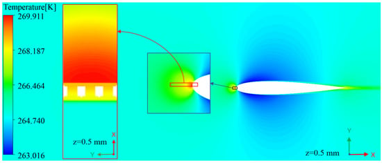
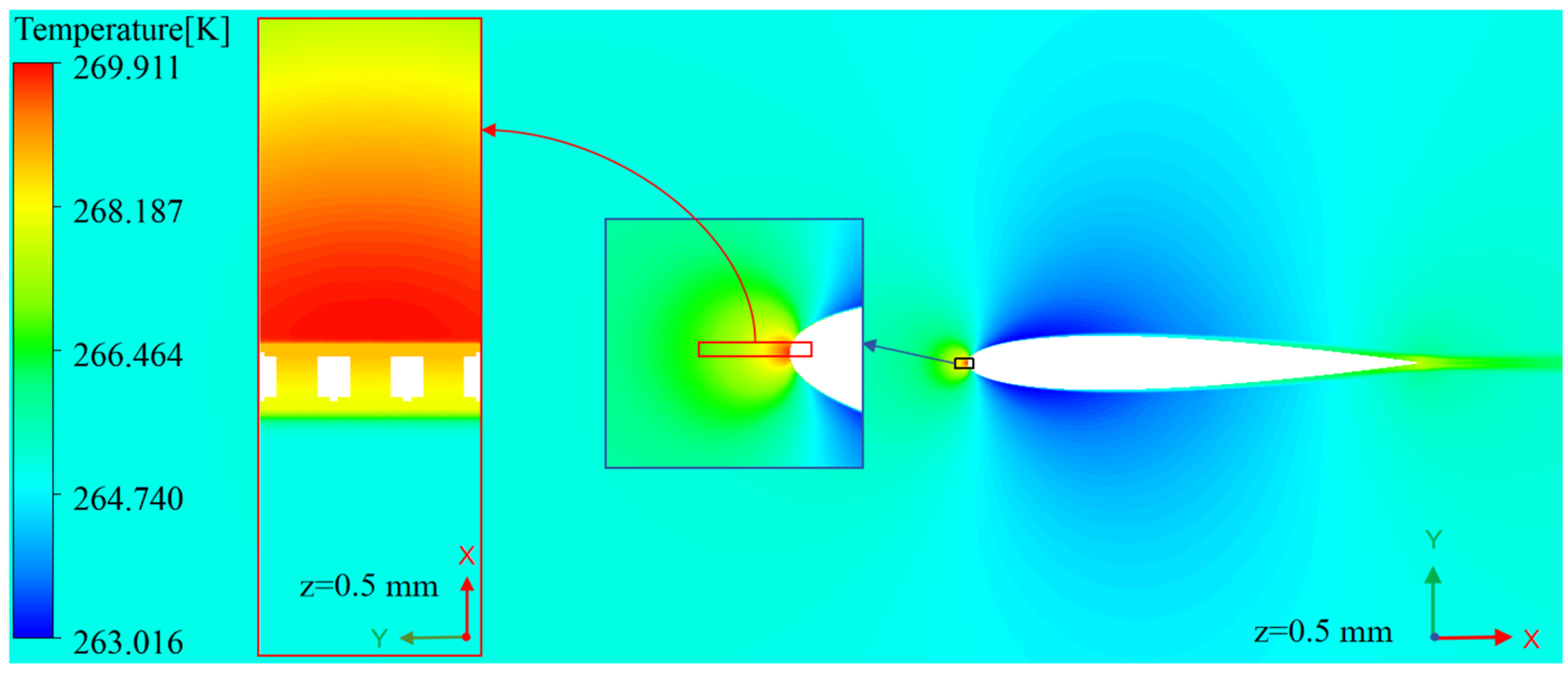
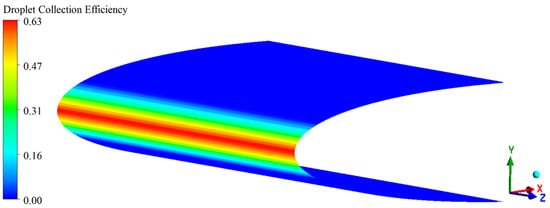
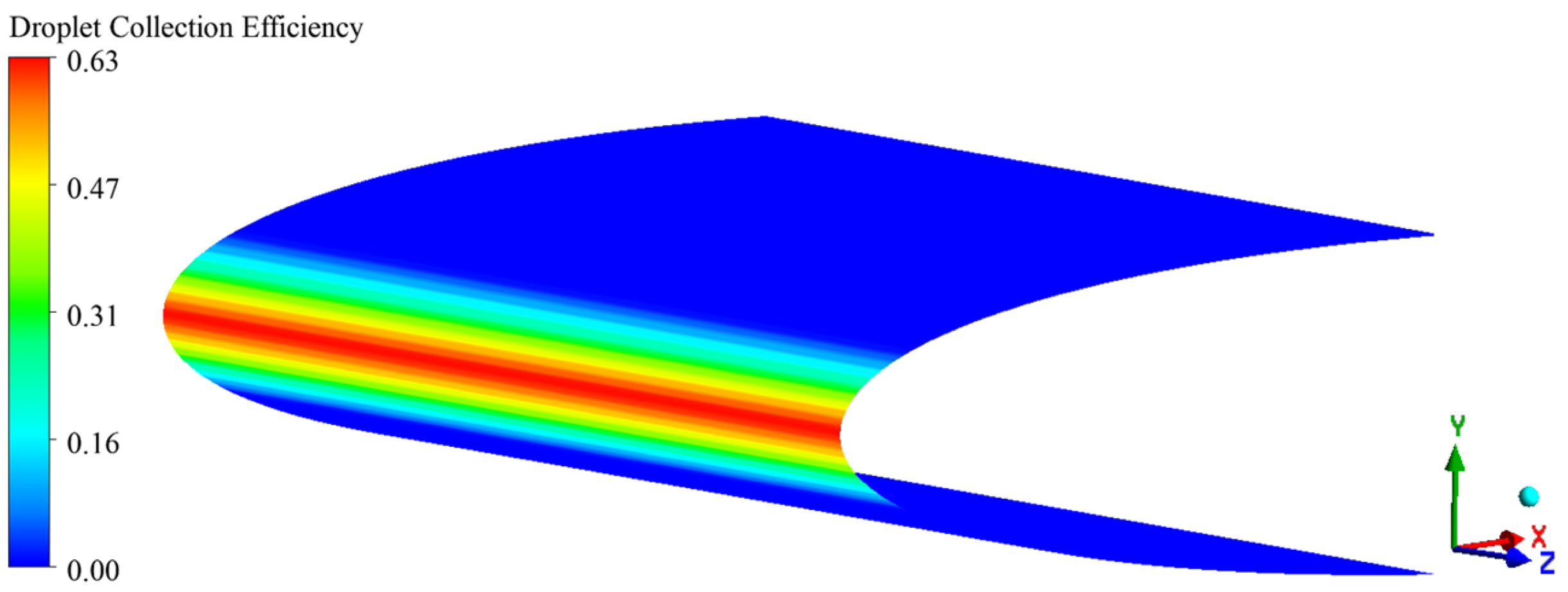
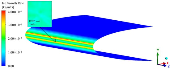
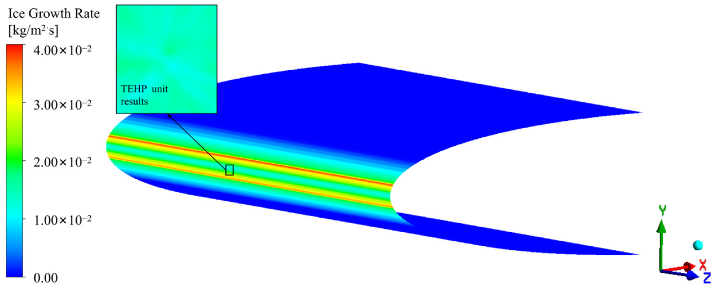
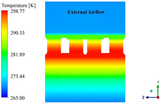
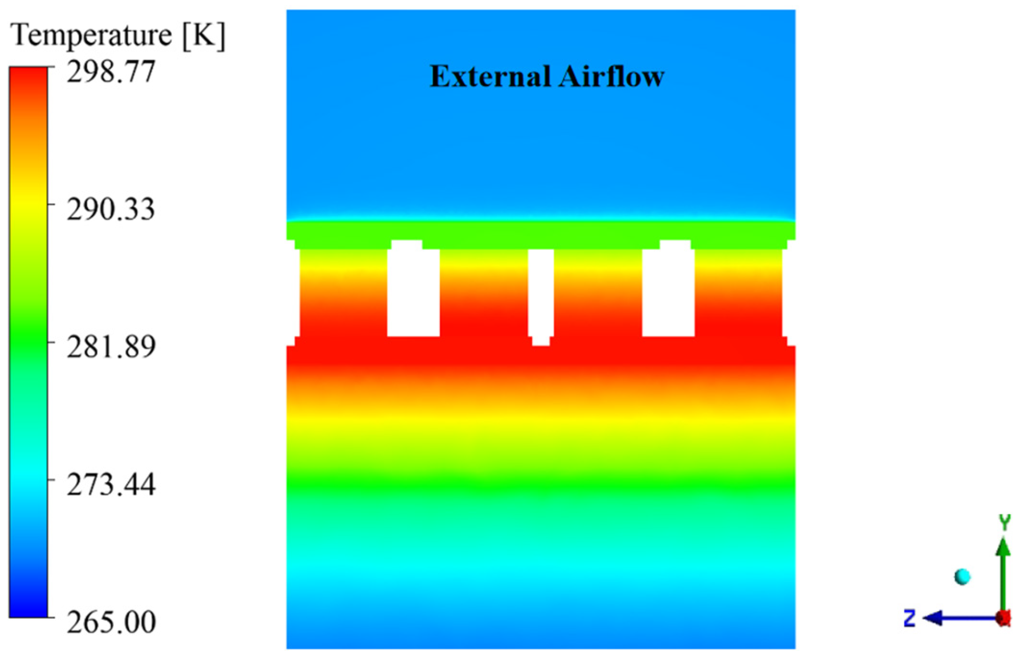
Under the above operating conditions, coupled simulations of the airflow, droplet impingement, and icing processes were conducted. The resulting temperature distribution of the external airflow field is shown in Figure 7. Figure 8 presents the steady-state droplet collection efficiency on the airfoil surface, with the maximum value occurring near the wing leading edge. Owing to the relatively high total temperature of the incoming flow (269.96 K), only a portion of the impinging water freezes locally, while the remaining liquid water migrates along the wing surface. Consequently, the maximum ice growth rate does not coincide with the peak droplet collection efficiency but appears on both sides of the peak impingement region, as shown in Figure 9. Over the prescribed 30 s icing period, the area-averaged ice growth rate within the selected TEHP unit section is approximately 0.0157 kg·m−2·s−1, with a comparatively uniform local distribution.
Figure 7.
Temperature distribution of the external flow field on the z = 0.5 mm plane.
Figure 8.
Steady-state distribution of droplet collection efficiency on the complete airfoil surface.
Figure 9.
Average ice growth rate distribution over a 30 s icing period on the complete airfoil surface and the selected TEHP unit region.
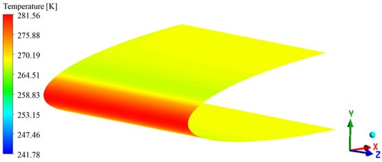
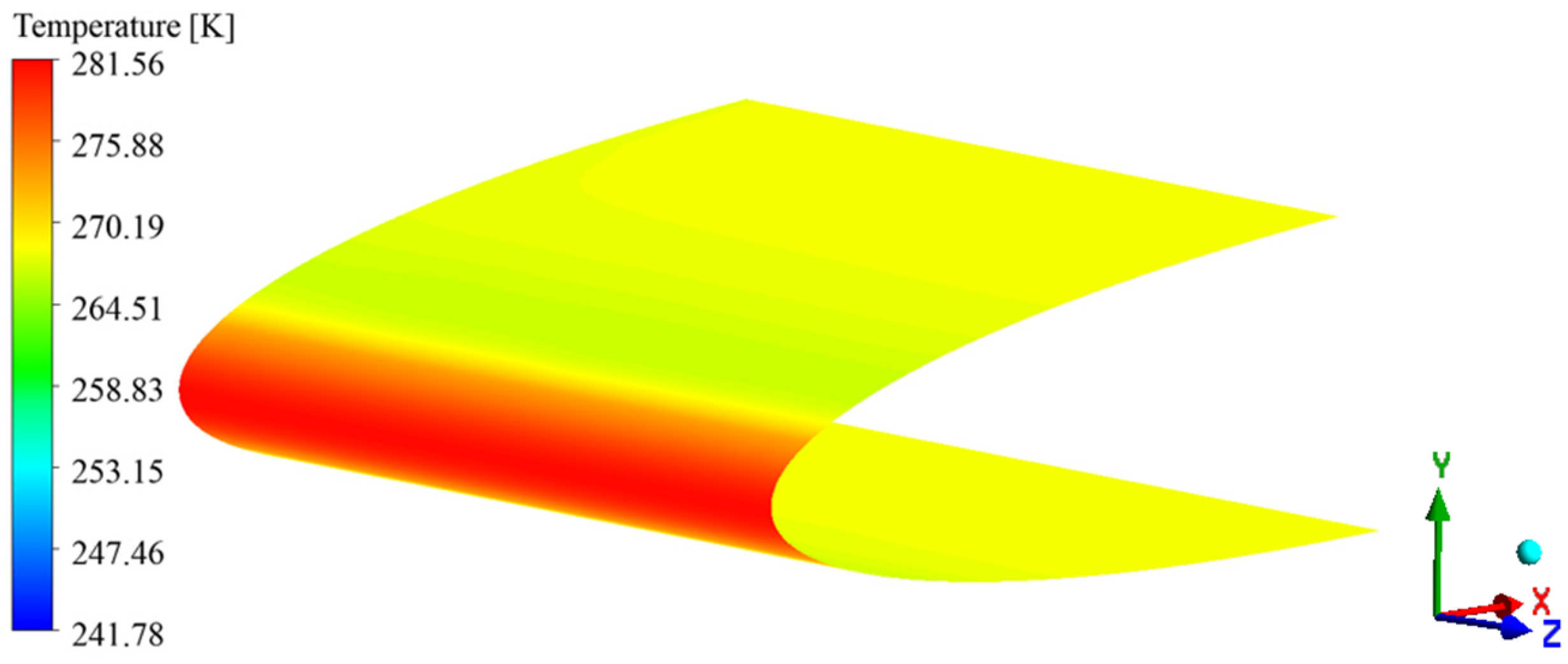
Based on the ice growth rate distribution over the wing surface, a 0.06 m chordwise region at the wing leading edge was designated as the primary deicing region. Figure 10 presents the temperature distribution obtained from the thermally coupled deicing simulation when a current of 1.5 A was applied only to the TEHP within the primary deicing region. After the TEHP thin film was coupled to the model, the wing-skin temperature increased markedly. However, because the heat supplied within the primary deicing region spreads along the wing skin in the chordwise direction, the resulting skin temperature is slightly lower than that predicted for an isolated TEHP unit. This chordwise heat spreading also contributes to an improvement in the COP of the TEHP.
Figure 10.
Wing-surface temperature distribution obtained from the thermally coupled TEHP deicing simulation (I = 1.5 A).
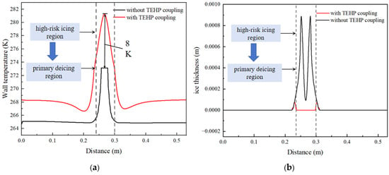
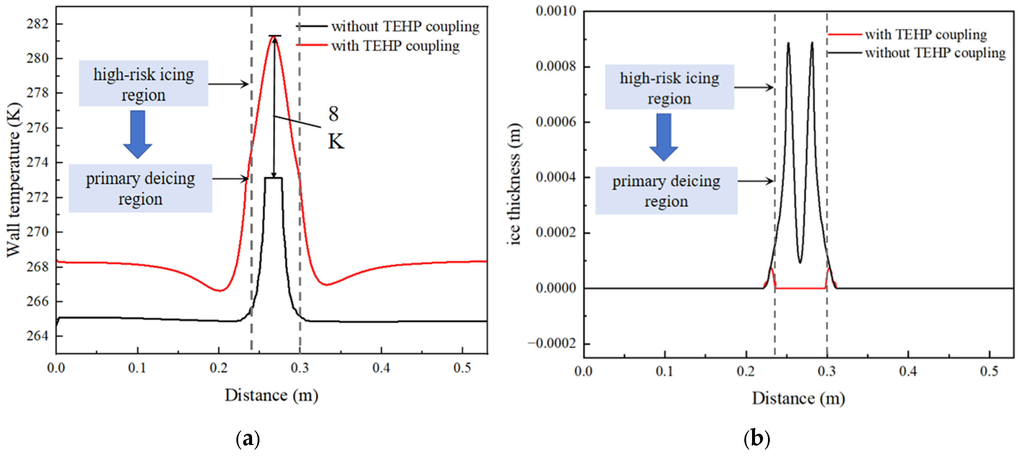
Figure 11a compares the chordwise wall-temperature distributions at z = 0 before and after TEHP coupling. After TEHP deicing was applied to the icing region, the surface temperature within the primary deicing region increased by approximately 8 K. At the edges outside this region, however, the wall temperature decreased slightly because of the influence of runback water. Figure 11b presents the corresponding chordwise ice-thickness distributions. Before deicing, the maximum ice thickness over the wing surface was approximately 0.92 mm, and the total ice mass was 0.01386 kg with a 30 s icing period. Of this amount, approximately 0.01317 kg, corresponding to about 95.0% of the total ice mass, was concentrated within the selected 0.06 m primary deicing region. After TEHP coupling at an input current of 1.5 A, the ice mass within the TEHP-covered primary deicing region was reduced to zero with the same icing period. Residual icing was confined to regions outside the actively heated zone, where the maximum ice thickness was approximately 0.0763 mm, and the remaining ice mass was 0.000344 kg. Accordingly, the total ice mass was reduced by approximately 97.4% relative to the pre-deicing condition. These results indicate that the TEHP layer effectively removes the ice within the actively heated primary deicing region, while only a small amount of residual ice remains outside this region.
Figure 11.
Chordwise distributions (z = 0) before and after TEHP coupling: (a) wall temperature and (b) ice thickness; (a) Chordwise wall-temperature distribution (z = 0) before and after TEHP coupling; (b) Chordwise ice-thickness distribution (z = 0) with and without TEHP coupling. The vertical dashed lines indicate the boundaries of the 0.06 m primary deicing region.
The performance of the TEHP was evaluated through thermally coupled simulations of a representative single TEHP unit. Accordingly, the COP values discussed in the following parametric analyses represent the unit-level thermoelectric performance rather than the system-level COP of the entire wing deicing layer. The complete airfoil model was used separately to evaluate the spatial distributions of airflow, droplet impingement, ice growth, water-film behavior, and wing-surface temperature during the deicing process.
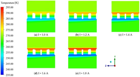
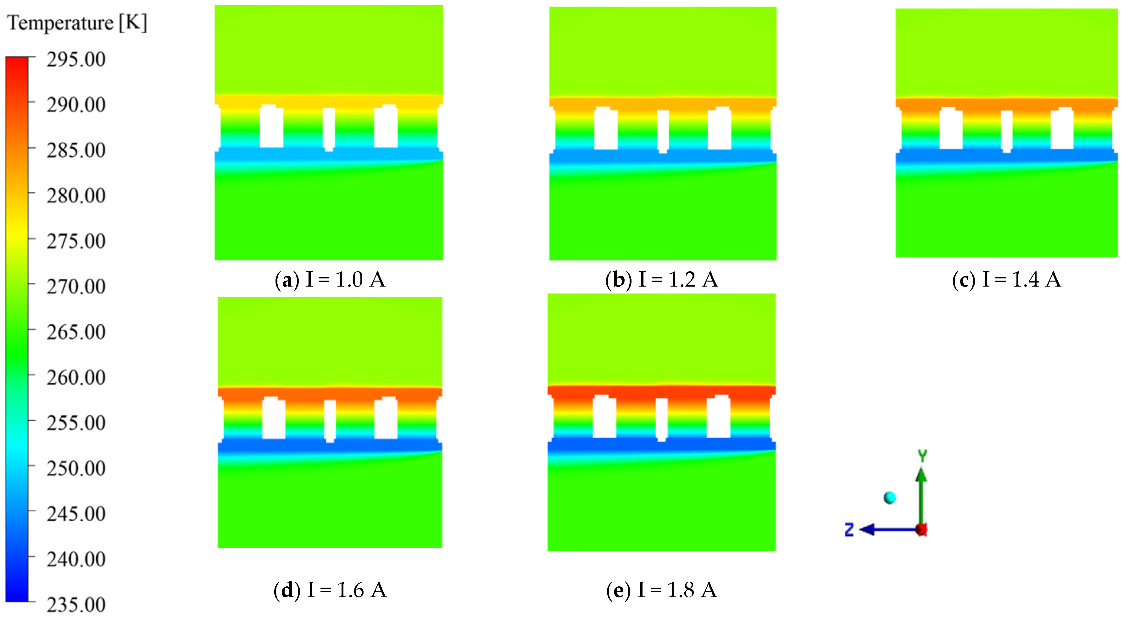
Input currents ranging from 1.0 to 1.8 A were applied to the TEHP, and the resulting steady-state temperature distributions on the coupled cross-section at x = 0 are shown in Figure 12. As the input current increases, the TEHP absorbs more heat from the internal airflow and transfers it to the aircraft skin, resulting in a progressive increase in the skin temperature. The higher steady-state skin temperature indicates enhanced heating performance. The steady-state temperature of the aircraft skin, which serves as the heat-releasing side, ranges from 277.92 to 292.61 K, indicating that the TEHP unit can provide sufficient surface heating for deicing under the investigated conditions.
Figure 12.
The steady-state temperature distribution of the TEHP unit cross-section (x = 0) after thermal-electrical coupling.
4.2. Comparative Analysis of TEHP Deicing and Electrothermal Deicing
To provide a consistent comparison between TEHP deicing and conventional electrothermal deicing, both systems were first evaluated under the same stagnant internal-air condition and at the same electrical power input. The same geometric model and computational mesh were used for both cases. For each operating condition, the voltage applied to the electrothermal heating layer was determined according to the electrical power consumption of the corresponding TEHP case. In addition to this baseline comparison, a TEHP case with forced internal airflow was included separately to evaluate the enhancement in heat-pumping performance resulting from cold-side convective heat transfer. Their COP values could therefore be compared under equivalent power-consumption conditions. For the electrothermal deicing case, the internal air was assumed to be stagnant. The resulting temperature distribution on the cross-section at x = 0 is shown in Figure 13. A temperature difference of approximately 10 K is observed between the two sides of the electrothermal heating layer. Under the stagnant-air conditions, the thick thermal boundary layer formed on the internal side suppresses heat dissipation toward the internal airflow.
Figure 13.
Steady-state temperature distribution on the cross-section (x = 0) under electrothermal heating.
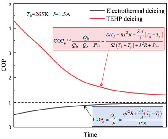
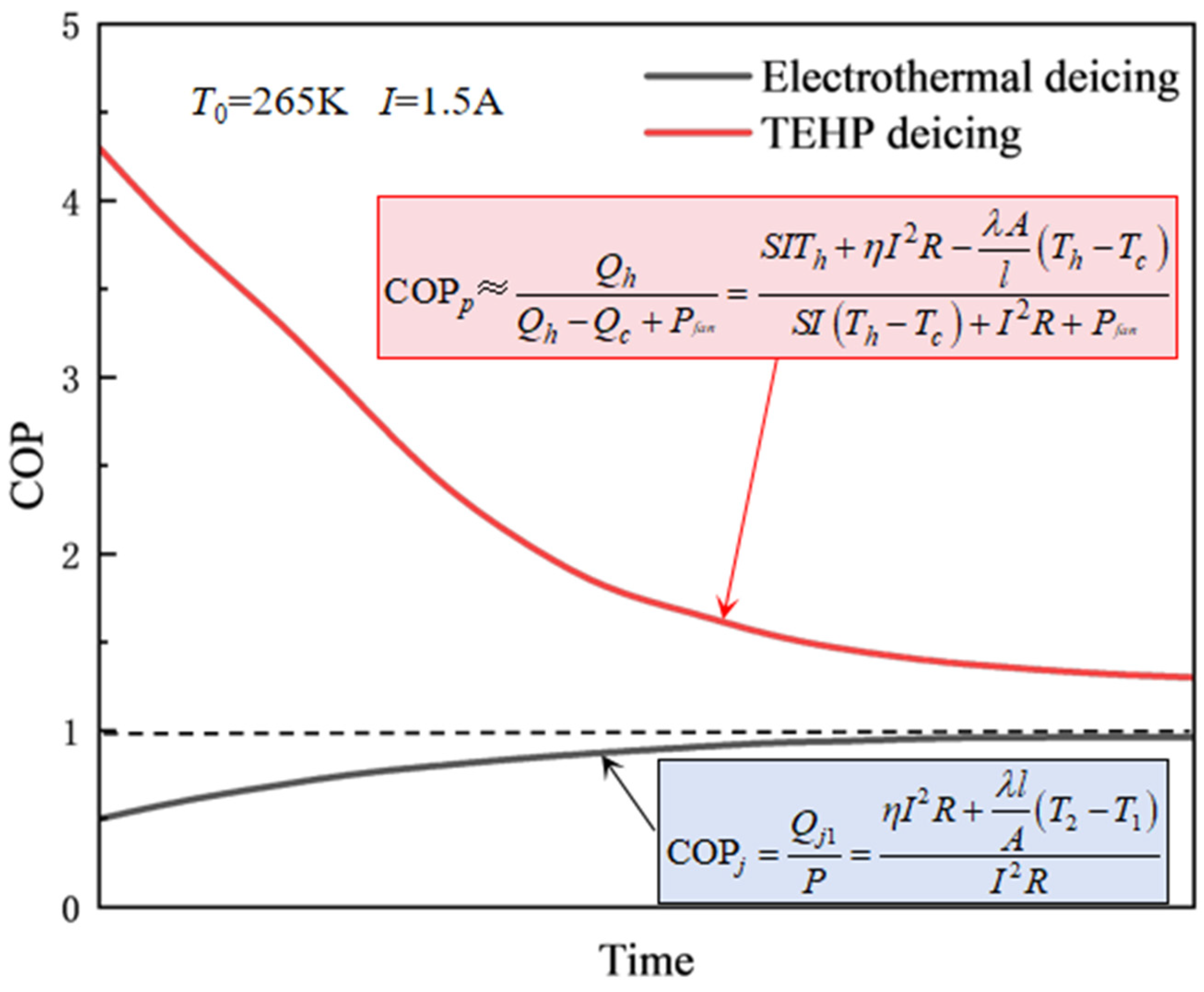
According to Equations (16) and (20), the COP of TEHP deicing remains greater than unity, whereas that of conventional electrothermal deicing remains below unity. Figure 14 schematically illustrates the theoretical evolution of the COP during thermal establishment; it is intended to explain the underlying thermoelectric behavior.
Figure 14.
Theoretical transient evolution of the COP for TEHP deicing and electrothermal deicing (T0 = 265 K, I = 1.5 A).
At the initial stage of electrothermal deicing, the temperatures on the two sides of the electrothermal heating layer are nearly equal. Consequently, the fraction of Joule heat transferred toward the aircraft skin, η, is approximately 0.5. As heating proceeds, the temperatures on both sides of the layer increase. Under the stagnant internal-air condition, the thick thermal boundary layer suppresses heat dissipation from the internal side, causing its temperature to rise more rapidly. The resulting temperature gradient promotes heat transfer toward the aircraft-skin side, thereby increasing η and causing the COP of electrothermal deicing to gradually approach unity.
For TEHP deicing, the initial temperature difference between the heat-absorbing and heat-releasing sides is small, resulting in weak heat conduction through the thermoelectric legs. Under this condition, the electrical power input remains small relative to the heat released at the heat-releasing side, and the initial COP can exceed 4. As heat is continuously pumped from the internal airflow to the aircraft skin, the temperature difference across the TEHP increases. This increase strengthens heat conduction from the heat-releasing side back toward the heat-absorbing side and increases the difference in Peltier heat between the two sides, leading to a gradual decrease in COP. The comparison therefore indicates that TEHP deicing provides a pronounced COP advantage over conventional electrothermal deicing, particularly during the initial transient response.
In addition to the difference in COP during the initial transient response stage, the steady-state stage accounts for a larger proportion of the total energy consumption during the deicing process. Therefore, based on the power consumption obtained from the TEHP simulations, the corresponding voltage applied to the electrothermal deicing system was determined to enable a comparison under equivalent input-power conditions.
To distinguish the intrinsic performance difference between thermoelectric heat-pump deicing and conventional electrothermal deicing from the additional enhancement provided by internal forced airflow, the comparison was conducted in two stages. First, TEHP deicing and electrothermal deicing were compared under identical stagnant internal-air conditions and the same electrical power input. This comparison provides a consistent baseline for evaluating the difference between the two heating mechanisms.
For conventional electrothermal deicing, the generated Joule heat is transferred toward both sides of the heating layer. Introducing forced airflow on the internal side would enhance heat removal from the inward-facing surface and would therefore tend to reduce the fraction of heat transferred toward the wing skin. Consequently, internal forced airflow does not provide the same beneficial mechanism for conventional electrothermal deicing as it does for the TEHP.
On this basis, an additional TEHP case with internal forced airflow was introduced to evaluate the enhancement associated with improved cold-side heat absorption.
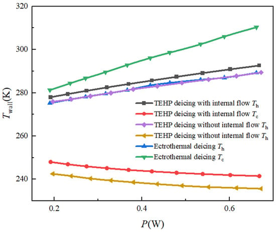
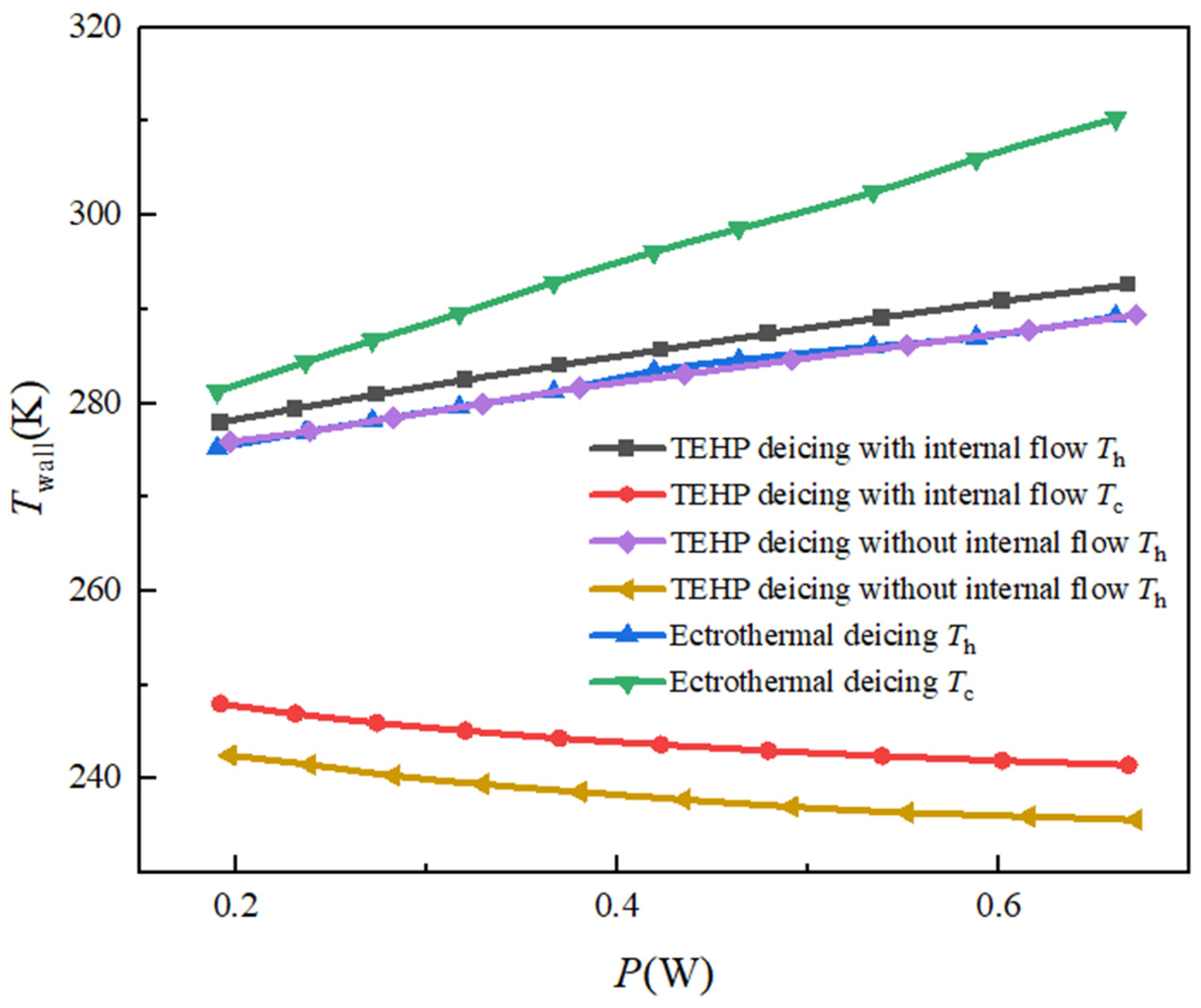
Figure 15 shows the relationship between the steady-state surface temperatures on both sides and the input power for TEHP deicing with and without internal airflow, as well as conventional electrothermal deicing. Under the same input power, the skin-side temperature of TEHP deicing with internal airflow is slightly higher than that of conventional electrothermal deicing, while the temperature for TEHP deicing without internal airflow is comparable to that of conventional electrothermal deicing. On the internal-air side, the surface temperature of conventional electrothermal deicing is substantially higher because the internal airflow is stagnant. In contrast, the heat-absorbing-side temperature of the TEHP remains considerably lower, particularly under the stagnant internal-air condition. With internal airflow, the heat-absorbing-side temperature increases because the circulating air continuously replenishes the heat absorbed by the TEHP. For conventional electrothermal deicing, the Joule heat generated in the electrothermal layer is transferred primarily toward the skin through thermal conduction driven by the temperature difference across the layer. Consequently, the temperature difference between the two sides increases with increasing input power.
Figure 15.
Steady-state surface temperature versus power consumption for TEHP and electrothermal deicing under different internal airflow conditions.
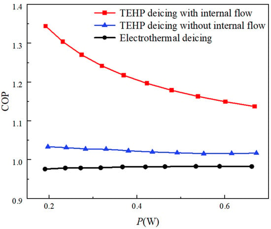
Figure 16 presents the relationship between the steady-state COP and the input power for the three deicing conditions. In the COP calculation for the TEHP with internal airflow, the power consumption required to drive the airflow was evaluated based on the internal flow passage shown in Figure 2. The cross-sectional area of the internal passage is approximately 0.0215 m2. For an internal airflow velocity of 5 m/s, the required fan power is estimated according to Equation (17) to be approximately 21.5 W. Since a single fan provides the circulating airflow for the entire TEHP deicing region, this power consumption corresponds to approximately 0.00304 W per TEHP unit. In comparison, the electrical power consumption of a single TEHP unit at the input current of 1.0 and 1.9 A are approximately 0.662 and 0.192 W. Therefore, the fan power allocated to each TEHP unit are only about 0.46% and 1.59% of the TEHP electrical power consumption. Accordingly, the fan-power contribution is less than 2% under the investigated conditions and has only a negligible influence on the reported unit-level COP.
Figure 16.
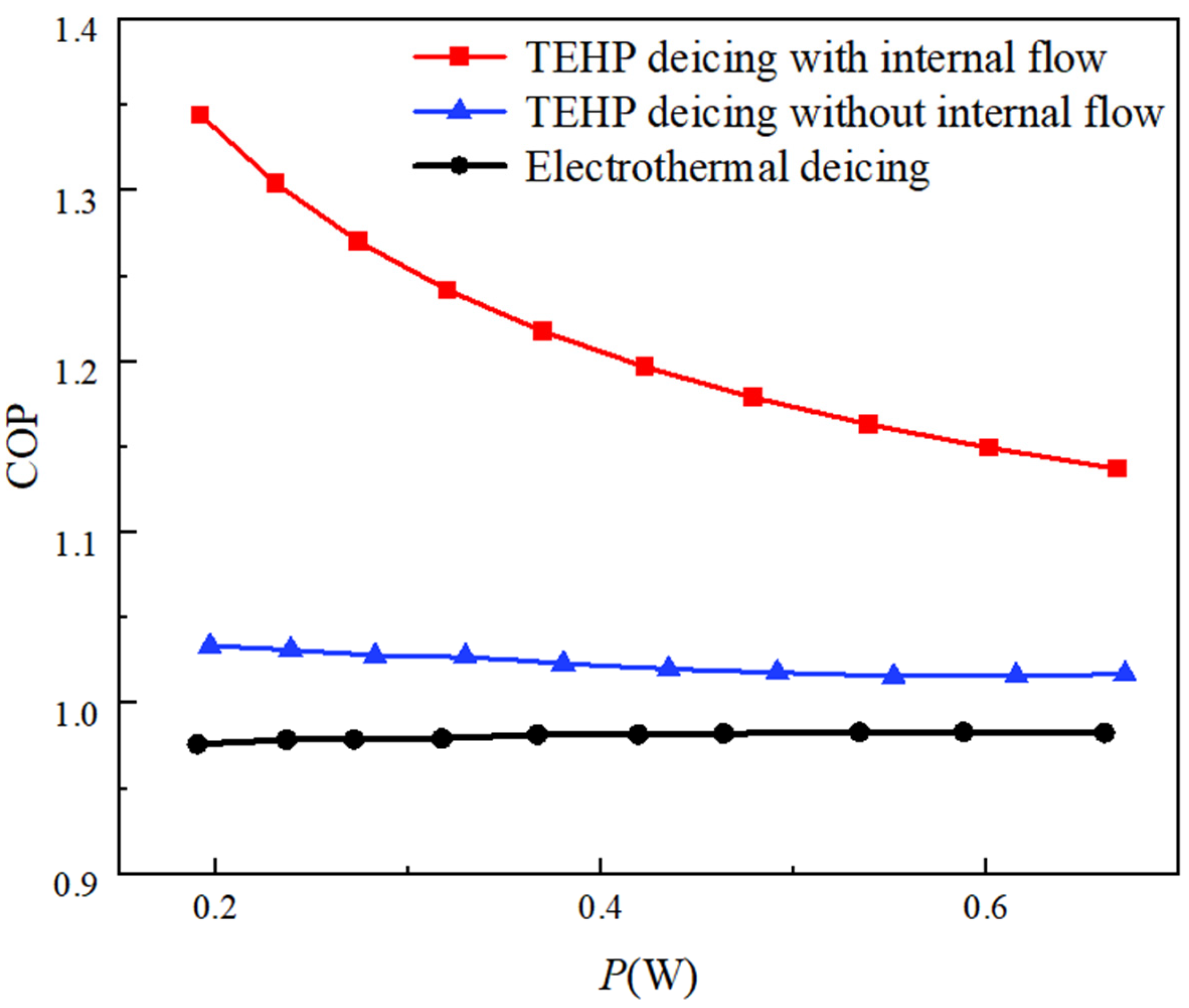
Steady-state COP versus power consumption for TEHP and electrothermal deicing under different internal airflow conditions.
As shown in Figure 16, the COP of conventional electrothermal deicing remains below unity, ranging from 0.96 to 0.98, whereas the COP of TEHP deicing remains above unity under both stagnant and forced internal-air conditions. Under the same stagnant internal-air condition and equal electrical power input, the TEHP exhibits a higher COP than conventional electrothermal deicing. Specifically, the COP improvements are approximately 3.479–5.88% over the investigated range, demonstrating that the TEHP itself provides an energy-efficiency advantage even without forced internal airflow. When a 5 m/s internal airflow is introduced to enhance heat absorption at the TEHP cold side, the corresponding COP improvements relative to conventional electrothermal deicing increase to 15.7% and 37.69%, respectively. These results show that TEHP deicing maintains a higher unit-level COP than conventional electrothermal heating under the investigated stagnant-air conditions, while internal forced convection further increases this advantage. It also shows that the TEHP COP decreases with increasing input current, although its heating capacity increases simultaneously. This result reflects a trade-off between heating capability and energy efficiency. In practical operation, the required electrical input is determined by the deicing heat load imposed by the external icing environment. Therefore, the investigated current range is intended to characterize the TEHP performance under different heating-demand levels rather than to identify the current corresponding to maximum heating capacity. For a given deicing requirement, an energy-efficient operating strategy would favor the minimum current that satisfies the required heat load or wing-skin-temperature criterion.
4.3. Analysis of the Effect of Internal Flow Velocity on Coupled Calculations
According to Equation (16), enhancing the heat absorption capacity Qc of the TEHP cold side from the low-temperature heat source is essential for improving the deicing COP. The heat absorbed at the TEHP heat-absorbing side is governed by both the air-to-surface temperature difference and the convective heat-transfer coefficient. In the present conjugate heat-transfer calculation, the heat-transfer coefficient is not prescribed as an independent boundary condition but is determined implicitly from the resolved internal airflow and temperature fields. Increasing the internal airflow velocity reduces the near-wall thermal resistance and consequently increases the effective convective heat-transfer coefficient. During TEHP deicing, when the internal airflow within the wing remains stagnant, a thick thermal boundary layer develops on the heat-absorbing side of the TEHP. Heat transfer in the internal airflow is then dominated by thermal conduction through the stagnant internal air, which limits the continuous heat absorption of the TEHP from the internal airflow. Consequently, a larger proportion of the heat released to the wing skin originates from Joule heating, causing the COP of the TEHP to approach unity.
Therefore, forced airflow circulation was introduced to enhance the heat-transfer capability of the TEHP cold side. Considering the heat dissipation requirements of onboard electrical components in more-electric low-altitude aircraft, the internal airflow can simultaneously enhance TEHP operation and assist in electronic-component cooling, enabling coordinated thermal management from electrical-component heat dissipation, to TEHP heat pumping, and finally to wing-skin heating.
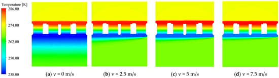
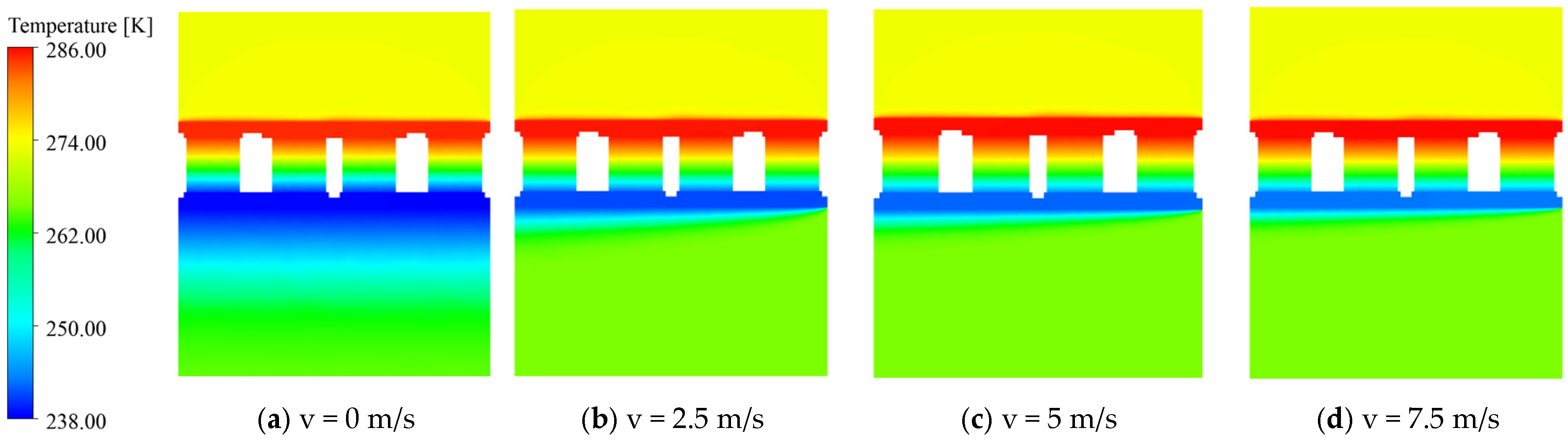
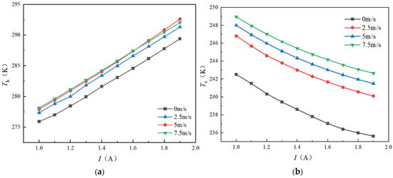
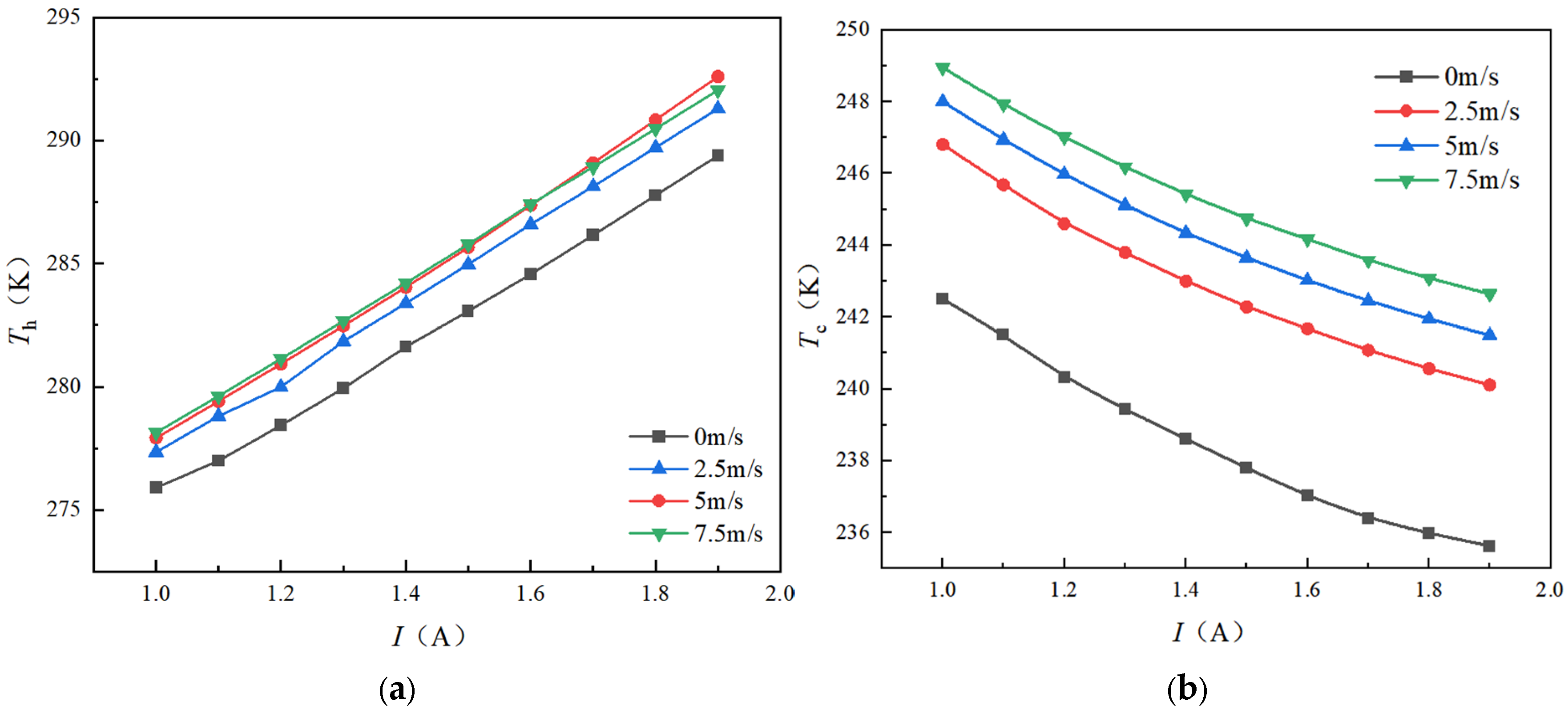
Figure 17 shows the temperature distributions on the TEHP unit cross-section (x = 0) under different internal airflow velocities ranging from 0 to 7.5 m/s along the spanwise direction. Under identical input current conditions, increasing the internal airflow velocity significantly reduces the thermal boundary layer thickness on the heat-absorbing side of the TEHP, thereby enhancing heat transfer between the internal airflow and the TEHP cold side. Figure 18 presents the variations in the TEHP heat-releasing-side temperature Th and heat-absorbing-side temperature Tc with the input current under different internal airflow velocities from stagnant conditions to 7.5 m/s. As the current increases, the temperature of the heat-releasing side increases approximately linearly, whereas the temperature of the heat-absorbing side gradually decreases, with the decreasing rate becoming less pronounced. Compared with the stagnant condition, the heat-releasing-side temperature of the TEHP with a 2.5 m/s internal airflow is consistently increased by 3–5 K. When the internal airflow velocity is further increased to 5 m/s and 7.5 m/s, the increase in the heat-releasing-side temperature becomes relatively limited.
Figure 17.
Temperature distributions on the TEHP unit cross-section x = 0 at different internal airflow velocities.
Figure 18.
TEHP surface temperature versus internal airflow velocity and current intensity; (a) The surface temperature of the heat-releasing side of the TEHP; (b) The surface temperature of the heat absorption side of the TEHP.
In contrast, the heat-absorbing-side temperature is more sensitive to the internal airflow velocity. With a 2.5 m/s internal airflow, the heat-absorbing-side temperature remains 5–8 K higher than that under the stagnant conditions. This indicates that introducing internal forced airflow effectively enhances heat absorption at the TEHP cold side, thereby improving the thermal pumping capability of the TEHP system.
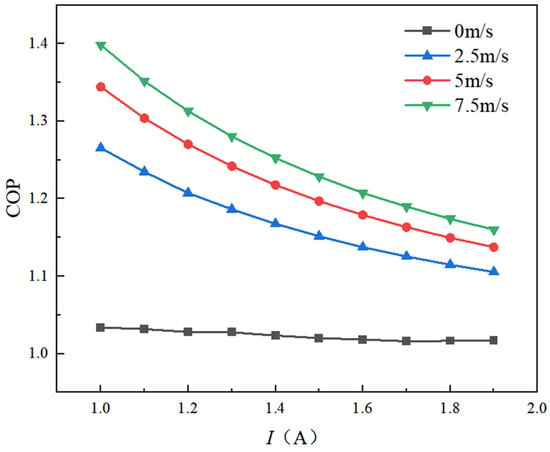
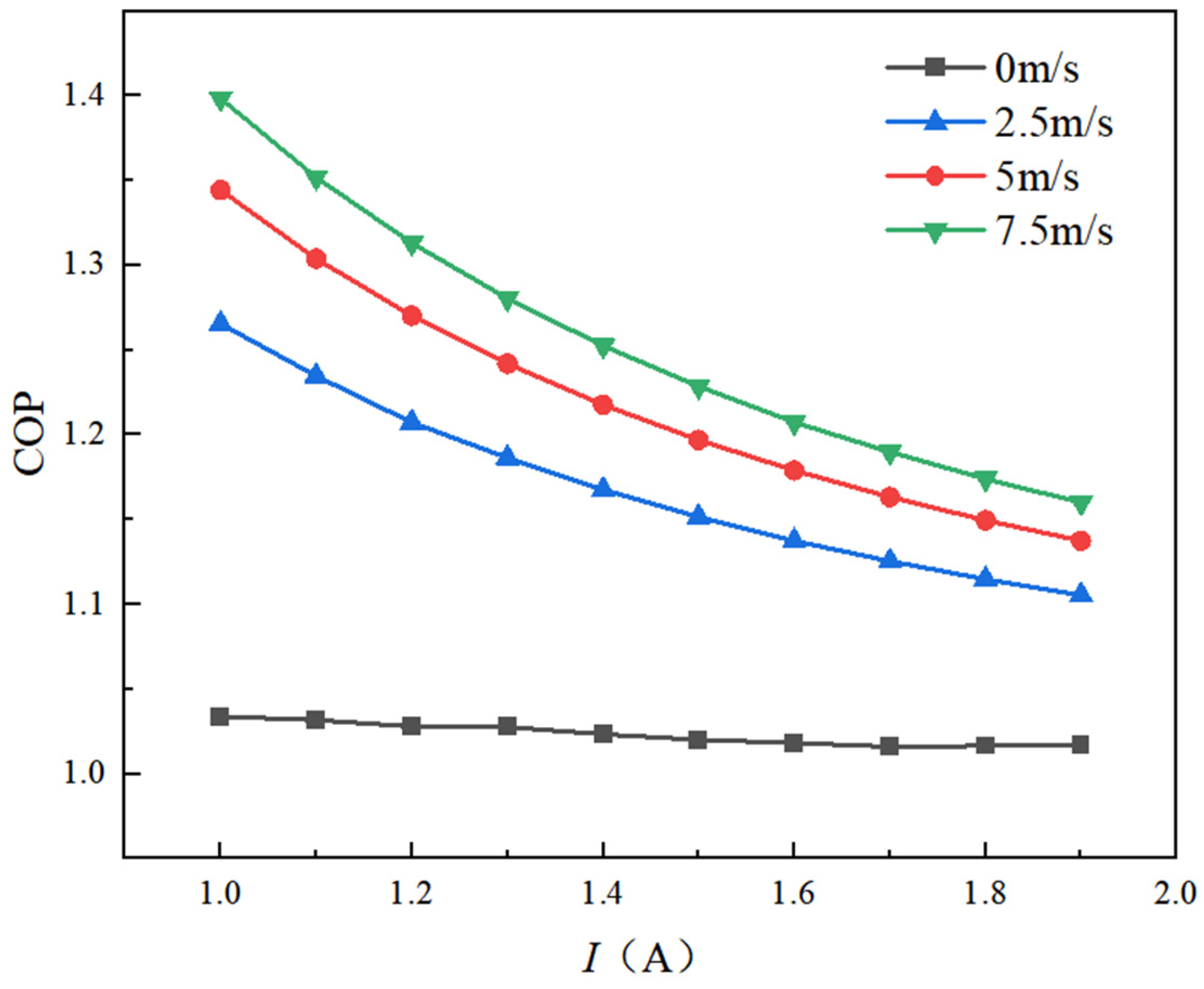
Figure 19 shows the variation in the coefficient of performance (COP) of the TEHP with input current under different internal airflow velocities. Under the stagnant internal-air condition, the heat absorbed by the TEHP at the heat-absorbing side is small but remains greater than zero. As a result, the COP remains close to unity and is only weakly affected by the input current. In general, the COP of the TEHP decreases with increasing current, whereas it increases with increasing internal airflow velocity.
Figure 19.
Variation in the TEHP COP with input current under different internal airflow velocities.
At an input current of 1.5 A, increasing the internal airflow velocity improves the COP by 12.33–19.86% relative to the stagnant condition. However, this improvement gradually diminishes as the current increases. This trend can be attributed mainly to the different dependencies of Joule heating and Peltier heat on the current: the Joule heating term is proportional to I2, whereas the Peltier heat is proportional to I. Therefore, according to Equation (17), as the current increases, the growth rate of power consumption exceeds that of the heat output, leading to a gradual decrease in COP. These results indicate that increasing the current beyond that required to satisfy the deicing heat load leads to diminishing energy-efficiency benefits. Therefore, current selection should prioritize the minimum electrical input required to achieve the target deicing performance rather than maximizing the heat output alone.
The Reynolds number based on the spanwise flow length was calculated as:
where ν is the kinematic viscosity of the fluid, x is the characteristic length, and U∞ is the incoming flow velocity. With a characteristic length Lx of 0.4288 m, the corresponding Reynolds numbers are approximately 7.1 × 10⁴, 1.42 × 10⁵, and 2.13 × 10⁵ for internal airflow velocities of 2.5, 5.0, and 7.5 m/s, respectively. These values remain below the commonly used transition Reynolds number for a developing flat-plate boundary layer (5 × 10⁵). Therefore, the laminar boundary-layer relation is used here to qualitatively explain the reduction in thermal boundary-layer thickness with increasing internal airflow velocity.
According to boundary-layer theory, the thickness of the laminar boundary layer δ along the wall satisfies:
Thus, the boundary-layer thickness is inversely proportional to U∞1/2. As the internal airflow velocity increases, the thermal boundary layer on the heat-absorbing side becomes thinner, which enhances heat transfer to the TEHP cold side and thereby improves the COP. When the internal airflow velocity is increased further, however, its influence on the COP gradually weakens.
5. Conclusions
This study introduces thermoelectric heat pump technology into the wing deicing system of low-altitude electric aircraft and develops a multiphysics numerical framework coupling icing, fluid flow, electrical conduction, and heat transfer. The framework is implemented in ANSYS Fluent using Fluent Icing, the Fluent Electric Potential module, and user-defined wall heat-flux expressions. Numerical simulations of the wing leading-edge deicing process under representative low-altitude icing conditions lead to the following conclusions:
- The integration of the TEHP deicing layer significantly increases the wing-skin temperature. As the input current increases, the skin temperature rises steadily, enabling the TEHP system to achieve nearly complete deicing within the selected 0.06 m primary deicing region under the investigated conditions.
- Under the investigated icing condition and at the same electrical power input, the unit-level COP of TEHP deicing exceeds that of conventional electrothermal deicing under identical stagnant internal-air conditions by approximately 3.479–5.88%. With a 5 m/s internal airflow, this improvement increases to 15.7–37.69% owing to enhanced heat absorption at the TEHP cold side. As the input current increases, the COP of TEHP deicing gradually decreases, whereas that of conventional electrothermal deicing exhibits only a slight increase. The preferred operating current should therefore be the minimum current that satisfies the required deicing heat load or wing-skin-temperature criterion rather than the current that maximizes heating capacity.
- Enhancing heat absorption at the heat-absorbing side is essential for improving the COP of the TEHP. Introducing spanwise internal airflow reduces the thermal boundary-layer thickness at the heat-absorbing side and enhances its heat-transfer capability. At an input current of 1.5 A, internal airflow velocities of 2.5–7.5 m/s increase the COP by 12.33–19.86% relative to the stagnant-air condition. Compared with the stagnant condition, the heat-releasing-side temperature increases by approximately 3–5 K, while the heat-absorbing-side temperature increases by approximately 5–8 K.
- The designed TEHP layer has an areal mass density of approximately 16.551 kg/m2, corresponding to about 0.993 kg per meter of wing span for the selected 0.06 m deicing region. Although the TEHP layer can be integrated within the wing structure without directly altering the external aerodynamic profile, its additional mass and the installation requirements of electrodes, wiring, bonding layers, and internal-airflow components impose additional constraints on lightweight wing design and should be considered in future aircraft-level integration.
These findings highlight the potential of thin-film TEHPs as an energy-efficient ice-protection technology for low-altitude electric aircraft. Further studies may extend the present framework to broader icing conditions, structural configurations, and control strategies for system-level optimization. It should be noted that the present study evaluates the COP at the representative TEHP-unit level and does not yet integrate the performance of all TEHP units over the complete deicing region. Since the external thermal and icing conditions vary spatially along the wing surface, the operating performance of individual TEHP units may also differ with installation location. Future work will therefore extend the present framework toward a system-level COP assessment that accounts for the spatial distributions of heat output and electrical power across the complete TEHP deicing layer.
Author Contributions
W.G.: Writing—original draft, Validation, Methodology, Investigation, Formal analysis, Data curation, and Conceptualization. J.C.: Writing—review and editing and Methodology. L.W.: Methodology and Investigation. S.Z.: Validation. J.X.: Writing—review and editing. All authors have read and agreed to the published version of the manuscript.
Funding
This research received no external funding.
Data Availability Statement
The data supporting the findings of this study are available from the corresponding author upon reasonable request. The complete dataset is not publicly available because some of the data form part of ongoing research and will be used in subsequent studies.
Conflicts of Interest
Author Liu Wang was employed by the Aviation Industry Corporation of China Wuhan Aviation Instrument Co., Ltd. The remaining authors declare that the research was conducted in the absence of any commercial or financial relationships that could be construed as a potential conflict of interest.
Abbreviations
The following abbreviations are used in this manuscript:
| TEHP | Thermoelectric Heat Pump |
| eVTOL | Electric Vertical Take-off and Landing |
| TEC | Thermoelectric Cooler |
| COP | Coefficient of Performance |
References
- Zhou, L.; Yi, X.; Liu, Q. A Review of Icing Research and Development of Icing Mitigation Techniques for Fixed-Wing UAVs. Drones 2023, 7, 709. [Google Scholar] [CrossRef] [Scilit]
- Tian, L.; Tu, J.; Liu, H.; Kong, W.; Han, N.; Tian, W. Experimental study on the icing hazards over the propeller of a Low-Altitude flight UAV under changeable liquid water content environment. Exp. Therm. Fluid Sci. 2025, 169, 111546. [Google Scholar] [CrossRef] [Scilit]
- Raj, P.L.; Yee, K.; Myong, R. Sensitivity of ice accretion and aerodynamic performance degradation to critical physical and modeling parameters affecting airfoil icing. Aerosp. Sci. Technol. 2020, 98, 105659. [Google Scholar] [CrossRef] [Scilit]
- Prasad, G.; Bruce Ralphin Rose, J. Experimental and computational study of ice accretion effects on aerodynamic performance. Aircr. Eng. Aerosp. Technol. 2020, 92, 827–836. [Google Scholar] [CrossRef] [Scilit]
- Rekuviene, R.; Saeidiharzand, S.; Mažeika, L.; Samaitis, V.; Jankauskas, A.; Sadaghiani, A.K.; Gharib, G.; Muganlı, Z.; Koşar, A. A review on passive and active anti-icing and de-icing technologies. Appl. Therm. Eng. 2024, 250, 123474. [Google Scholar] [CrossRef] [Scilit]
- Wang, X.; Li, Q.; Wang, Y.; Kosonen, R.; Liu, S.; Zhang, Y.; Khan, D.A.; Jiang, Y. Review of exploration of aircraft de/anti-icing mechanism and airborne application of superhydrophobic materials. Therm. Sci. 2025, 29, 2899–2913. [Google Scholar] [CrossRef] [Scilit]
- Cui, Y.; Dai, N.; Han, C. Structural-Integrated Electrothermal Anti-Icing Components for UAVs: Interfacial Mechanisms and Performance Enhancement. Aerospace 2025, 12, 719. [Google Scholar] [CrossRef] [Scilit]
- Wang, T.; Zhang, W.; Chen, J.; Li, S.; Yu, L.; Zhu, D.; Mao, X. Power optimization of the aircraft electrothermal de-icing heaters. Appl. Therm. Eng. 2025, 280, 128236. [Google Scholar] [CrossRef] [Scilit]
- Guo, H.; Liu, M.; Xie, C.; Zhu, Y.; Sui, X.; Wen, C.; Li, Q.; Zhao, W.; Yang, J.; Zhang, L. A sunlight-responsive and robust anti-icing/deicing coating based on the amphiphilic materials. Chem. Eng. J. 2020, 402, 126161. [Google Scholar] [CrossRef] [Scilit]
- Ma, F.; Zhu, Z.; Wang, D.; Jin, X. Numerical Analysis of the Wing Leading Edge Electro-Impulse De-Icing Process Based on Cohesive Zone Model. Appl. Sci. 2024, 14, 2777. [Google Scholar] [CrossRef] [Scilit]
- Shoeibi, S.; Rahbar, N.; Esfahlani, A.; Kargarsharifabad, H. Application of simultaneous thermoelectric cooling and heating to improve the performance of a solar still: An experimental study and exergy analysis. Appl. Energy 2020, 263, 114581. [Google Scholar] [CrossRef] [Scilit]
- Yu, Y.; Zhu, W.; Kong, X.; Wang, Y.; Zhu, P.; Deng, Y. Recent development and application of thin-film thermoelectric cooler. Front. Chem. Sci. Eng. 2020, 14, 492–503. [Google Scholar] [CrossRef] [Scilit]
- Marzougui, M.; Chargui, R.; Snoussi, L.; Bechir, N. Numerical analysis of a hybrid solar heat pump system integrating thermoelectric generators and phase change materials for winter heating applications. J. Build. Eng. 2026, 120, 115436. [Google Scholar] [CrossRef] [Scilit]
- Zhou, B.; Cheng, X.; Liang, X. Conditional extremum optimization analyses and calculation of the active thermal control system mass of manned spacecraft. Appl. Therm. Eng. 2013, 59, 639–647. [Google Scholar] [CrossRef] [Scilit]
- Corbett, S.; Gautam, D.; Lal, S.; Yu, K.; Balla, N.; Cunningham, G.; Razeeb, K.M.; Enright, R.; McCloskey, D. Electrodeposited thin-film micro-thermoelectric coolers with extreme heat flux handling and microsecond time response. ACS Appl. Mater. Interfaces 2021, 13, 1773–1782. [Google Scholar] [CrossRef] [Scilit]
- Boudreaux, P.; Hall, C.; Gluesenkamp, R.K.; Karman, S.; Willocks, J.; Patel, V.; Gehl, A. Fast-airflow tumble clothes dryer with small thermoelectric heat pump: Experimental evaluation. Therm. Sci. Eng. Prog. 2024, 55, 102960. [Google Scholar] [CrossRef] [Scilit]
- Liao, M.; Lu, Y.; Liu, J.; Deng, D.; Fan, X.; He, Z. Research on current strategies for thermoelectric coolers to achieve maximum cooling capacity under convective heat dissipation conditions. Int. Commun. Heat Mass Transf. 2026, 176, 111323. [Google Scholar] [CrossRef] [Scilit]

Disclaimer/Publisher’s Note: The statements, opinions and data contained in all publications are solely those of the individual author(s) and contributor(s) and not of MDPI and/or the editor(s). MDPI and/or the editor(s) disclaim responsibility for any injury to people or property resulting from any ideas, methods, instructions or products referred to in the content. |
© 2026 by the authors. Licensee MDPI, Basel, Switzerland. This article is an open access article distributed under the terms and conditions of the Creative Commons Attribution (CC BY) license.