


Abstract
Conventional fixed phase-shift strategies for parallel PV converters fail to minimize output ripple under heterogeneous input conditions, while communication-based synchronous methods incur high costs and reliability risks. Furthermore, standard global optimization algorithms like conventional Particle Swarm Optimization (PSO) suffer from slow convergence, hindering real-time application. To address these limitations, this paper proposes a communication-free distributed ripple suppression method based on an enhanced PSO with randomized phase shifting. Unlike traditional approaches, our method enables autonomous convergence without inter-unit communication. Crucially, a randomized pre-scanning mechanism narrows the search space, accelerating convergence significantly. Simulation results demonstrate that the proposed method reaches a steady state in merely 5 ms, which is 50% faster than conventional PSO (~10 ms) and eliminates communication latency. Under severe heterogeneous conditions, the technique reduces output voltage ripple to 0.66 V (a 53% reduction) compared to the unoptimized 1.21 V, vastly outperforming fixed interleaving strategies that show negligible improvement. The approach also ensures robust stability during load steps and plug-and-play operations, offering a superior low-cost and high-speed solution for distributed PV systems.
1. Introduction
Solar photovoltaic (PV)power generation offers advantages such as cleanliness, renewability, and abundance of energy resources. Its application has become increasingly widespread in the context of traditional fossil energy shortages [1]. DC-DC converters, which are widely used in PV power generation, have also undergone significant development. Among various technical routes, multi-module parallel operation to achieve high-capacity power supplies is recognized as one of the key directions in the development of modern power conversion technology [2]. By connecting multiple power modules in parallel to share the load power, the current stress on the main switching devices in each module is greatly reduced, thereby fundamentally improving reliability and reducing costs. Furthermore, multiple parallel modules allow flexible configuration of various power capacities, replacing serial production with modularization. This shortens the development and production cycles, reduces costs, and enhances the standardization, maintainability, and interchangeability of various switching power supplies.
However, due to the inherent characteristics of converters, PV systems often exhibit certain voltage ripples in their output, which adversely affects both the output power and system stability [3,4]. In multi-converter parallel systems, appropriate control strategies can suppress the output ripple to some extent. Therefore, how to reduce the output voltage ripple in multi-converter parallel PV systems has attracted widespread attention from researchers [5,6,7].
For a uniform input signal, parallel-connected converters generate output current ripples of the same magnitude, attributed to the switching properties of DC-DC circuits. If the phase of the control signal for each converter is adjusted, the phase of the output current ripple of each converter will shift accordingly [8,9]. When the control signals of all converters are in phase, the output current ripples reach their peaks and valleys simultaneously, resulting in maximum ripple on the bus voltage. Conversely, if the control signals of individual converters are staggered with a certain phase shift, the current ripples can cancel each other out, thereby reducing the overall ripple on the bus. For a system with N converters, the ideal phase shift between control signals is 360°/N [10].
Taking a three-phase interleaved converter as an example. When the three input signals are identical, configuring the PWM waves of the three converters with a 120° phase difference enables mutual cancellation of current ripples, ultimately reducing the output ripple. If the three input signals are not identical, the optimal phase shift must be recalculated [11].
However, in multi-module parallel-connected photovoltaic (PV) systems, the physical separation between PV arrays makes inter-converter communication challenging. Additionally, difficulties in time reference synchronization further hinder the precise coordination of phase shifts among converters to achieve optimal performance. Moreover, due to varying and unstable input conditions across individual PV units, the ideal phase shift between converters is difficult to determine analytically.
Reference [12] proposed a parallel interleaving method by delaying the clock signals of individual converters by specified phase shifts to achieve parallel interleaved control. However, this approach cannot quickly adapt to changes in the number of converters, as it requires pre-calculation of specific phase shifts and adjustments to the control system. Reference [13] introduced an additional phase communication line between each converter and its two adjacent converters, ensuring equal phase differences among every three adjacent converters, including the unit itself. This method necessitates extra communication lines and performs poorly when applied to converters with different parameters (which require different phase shifts). Reference [14] employed a phase-sweeping strategy, traversing all possible phase scenarios at fixed intervals to identify the phase configuration that minimizes output ripple. Nevertheless, this method involves substantial computational effort, as it requires evaluating the entire phase range. Reference [15] derived the optimal phase shifts for three converters to minimize output ripple under varying input amplitudes and duty cycles. However, this theoretical framework is limited to three converters and involves complex calculations, making it difficult to implement in practice.
To overcome these limitations, this paper proposes a distributed, communication-free ripple suppression technique based on a Particle Swarm Optimization (PSO) algorithm, which employs randomized variable phase shifts for multi-module parallel-connected systems. This approach enhances conventional interleaving strategies by allowing converters to autonomously adjust their phase shifts without communication, thereby significantly reducing output voltage ripple. Furthermore, it improves the convergence speed and global optimization capability of the algorithm. The proposed method effectively adapts to diverse converter input conditions and rapidly responds to converter plug-and-play operations, ensuring that the bus ripple remains minimized under dynamic operating conditions.
Compared with conventional PSO algorithms that only employ personal best and global best terms to search the full phase range, the proposed method introduces an additional control term based on the circuit characteristics. This term helps to preliminarily narrow down the optimal phase region before further optimization. By integrating the algorithm with the inherent properties of the converter circuit, the proposed approach can achieve faster convergence speed and better optimization performance.
The main contributions of this paper are twofold. First, an optimization algorithm is introduced for ripple suppression in parallel PV converters, which replaces the conventional exhaustive phase searching from 0° to 360° and greatly improves the optimization efficiency. Second, an enhanced PSO adapted to circuit characteristics is proposed, where an additional control term derived from circuit properties is added to narrow the search range and achieve faster convergence and better global optimization performance.
2. Materials and Methods
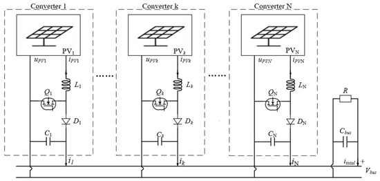
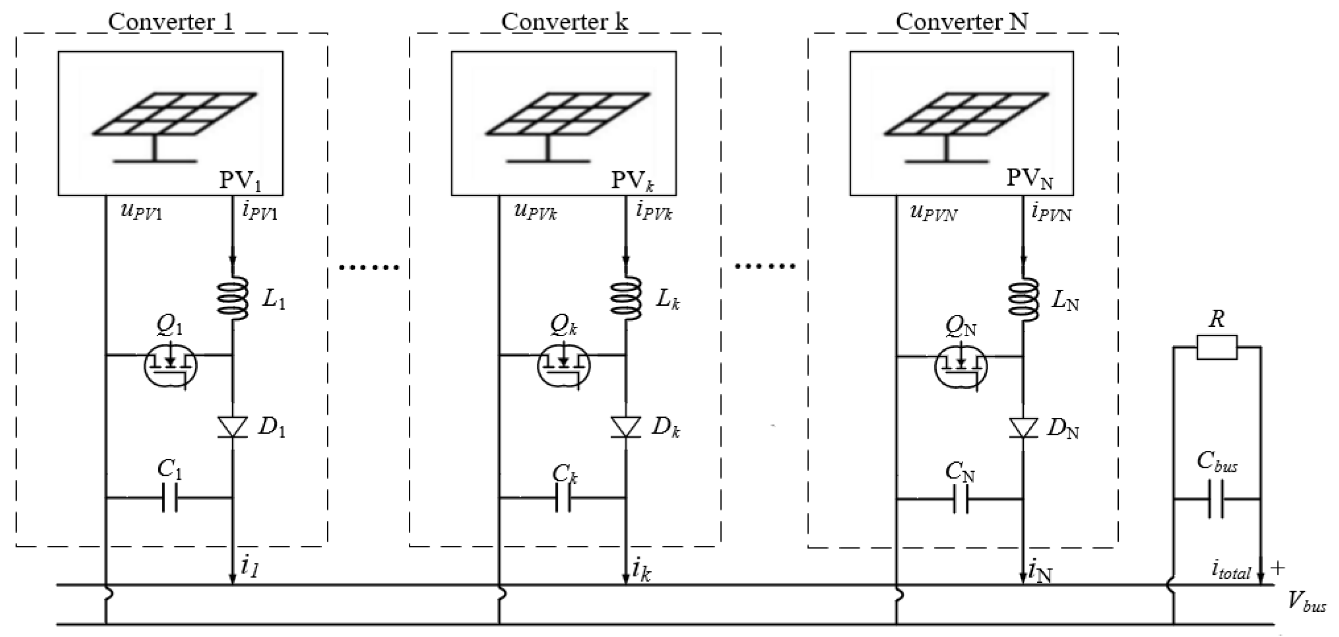
The current or voltage in Figure 1 can be decomposed into corresponding DC and AC components, for example:
Figure 1.
System structure of the paralleled PV with distributed converters.
Other current or voltage quantities follow the same principle and will not be listed individually here. The AC component will be the focus of our discussion.
As shown in Figure 1. When converters are connected in parallel, the total current ripple on the bus can be regarded as the superposition of the inductor current ripples from each individual converter , expressed as:
where N is the total number of converters. Due to differences among converters and photovoltaic devices, the input characteristics exhibit certain variations. The term in the equation can be decomposed using Fourier analysis, yielding:
where represents the amplitude of the ripple current, and indicates the phase angle of the ripple current.
At the bus terminal, due to the effect of capacitive reactance, a phase difference exists between the bus voltage ripple and the current ripple . Considering the bus impedance denoted (including R and ) as Z, the relationship can be expressed as:
For the k-th converter, when analyzing the bus voltage while excluding the influence of its self-induced ripple, the current and voltage ripples generated by the remaining converters can be attributed to:
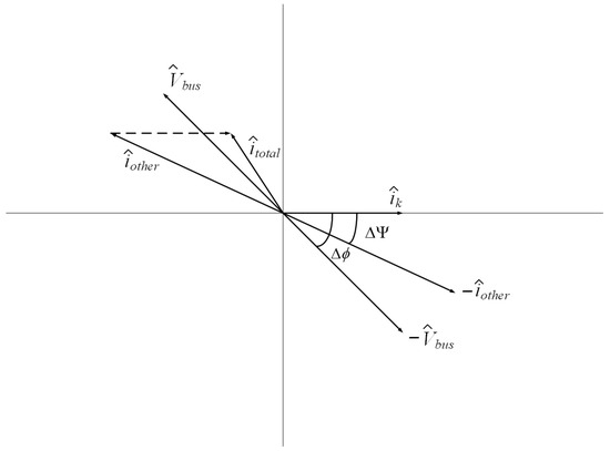
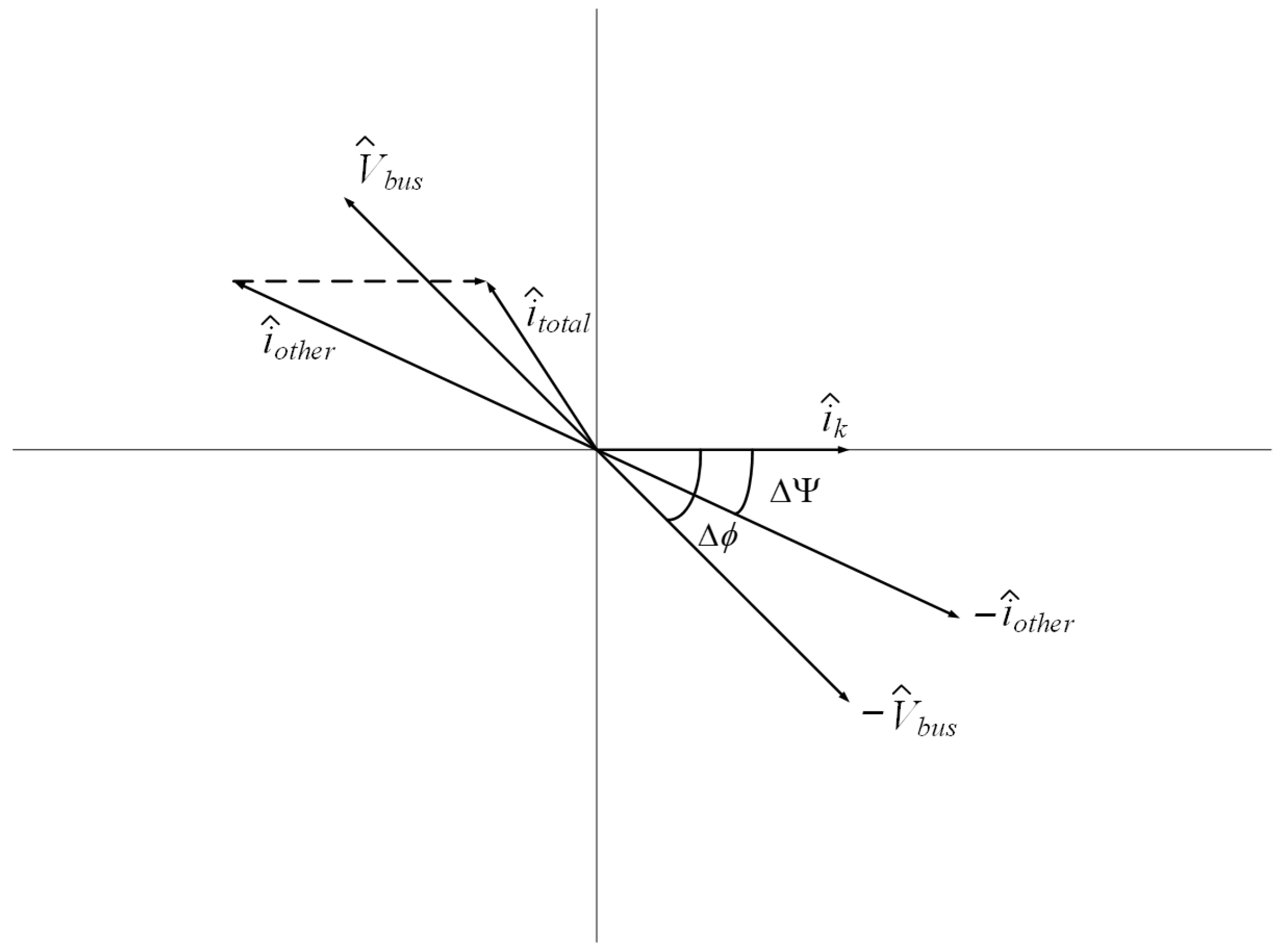
where is the total current from the other converters. Due to the capacitive reactance on the bus, the phase of the bus voltage ripple consistently lags that of the bus current. For simplicity of representation, the phase angle of each converter is referenced to itself as zero, leading to the relationship illustrated in the figure below [16]:
As shown in Figure 2, following the same notation as , we designate as the phase of and designate as the phase of . Therefore, represents the phase difference between and , while represents the phase difference between and . The phase of signal should be precisely opposite to that of signal to minimize ripple, namely:
where indicates the phase angle of the bus current. Therefore, the ideal objective in adjusting is to achieve = 0, which yields the following control strategy
where C is the control coefficient. However, due to the absence of communication, we cannot actually know the current phase of the other converters. Considering that and have the same phase direction relative to , we can use instead of for control, namely:
Figure 2.
Vector Diagram of Converter Parameters.
This approach will introduce certain errors, namely:
where represents the control error induced by the absence of communication, and its value varies under different conditions. Therefore, we propose the use of the PSO algorithm to optimize the system and eliminate this error.
The PSO algorithm is a computational method inspired by the social foraging behavior of bird flocks. In PSO, each potential solution is represented as a “particle” in the search space. These particles navigate through the solution domain by interacting with both their own historical experience and the collective knowledge of the swarm to rapidly converge toward an optimal solution. During the iterative process, the velocity and position of each particle are updated in each generation. The fitness of each particle is evaluated based on an objective function. The algorithm maintains records of the best position encountered by each particle, which is defined as personal best (pbest), and the best position found by the entire swarm, which is defined as global best (gbest). These guide the search toward promising regions, ultimately identifying the global optimum [17,18,19].
Considering the aforementioned control strategy and the PSO algorithm, we can derive the following control law:
where n denotes the nth iteration of the PSO algorithm. represents the individual optimal solution of the converter in the PSO algorithm iteration, while denotes the global optimal solution.
The third term corresponds to the control strategy presented in Equation (9), which satisfies the following expression:
and incorporates the random number required by the PSO algorithm, enabling the algorithm to avoid becoming trapped in local optima during iteration.
The first two terms and are used to eliminate the error .
In the third control term, enabling the algorithm to search for the optimal solution within an appropriate range. and are the control coefficients for these two terms, while and are also random numbers.
It can be observed that the algorithm should initially prioritize the third term with a larger coefficient, enabling the particle phase to rapidly converge to and approach the vicinity of the optimal solution . Subsequently, the weight of the first two terms should gradually increase, and their coefficients should be enlarged, allowing particles to perform PSO optimization within this range to find the optimal solution. Therefore, the bus ripple can be considered as a control coefficient, namely:
where represents the ripple amplitude and A is an empirical coefficient that can be adjusted based on the actual ripple value generated by the circuit.
The represents the inertia coefficient, which determines the particle’s tendency to retain its previous velocity. A higher value of promotes global exploration, while a lower value favors local optimization. Typically, is implemented as a dynamic parameter that decreases linearly with the number of iterations. However, as indicated in earlier analysis, the optimal solution for the converter should be confined near the point where its phase is opposite to that of the bus ripple (i.e., where = 0). This implies that when is large, the solution is more likely to be trapped in a local optimum, and the particle should emphasize global search (i. e., a larger . Conversely, when is small, the optimal solution lies within a narrower range, and should be correspondingly reduced. Considering that the value of is typically a fixed value between 0.3 and 0.8 [20], the control strategy proposed in this paper requires to be adjusted based on the number of iterations. Therefore, by integrating the value range of and empirical data from the simulation process, the value of in this paper is set as follows:
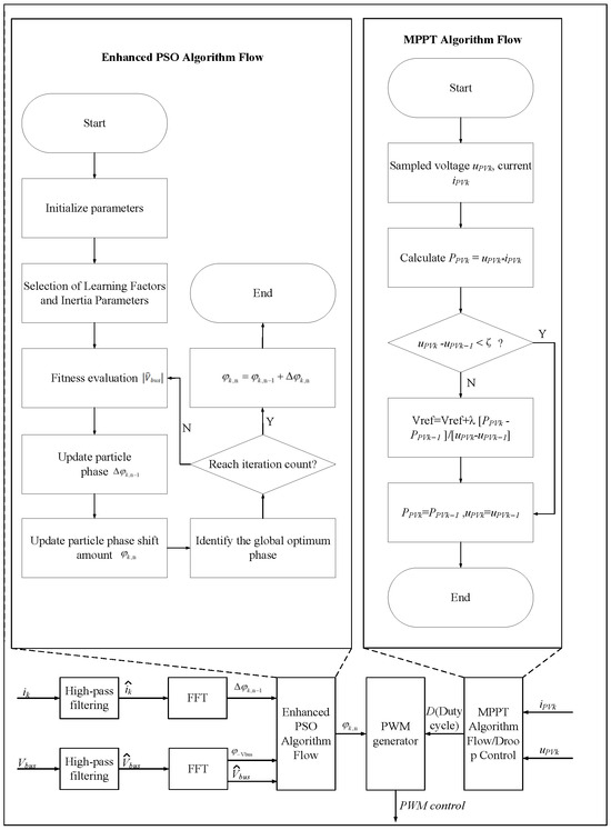
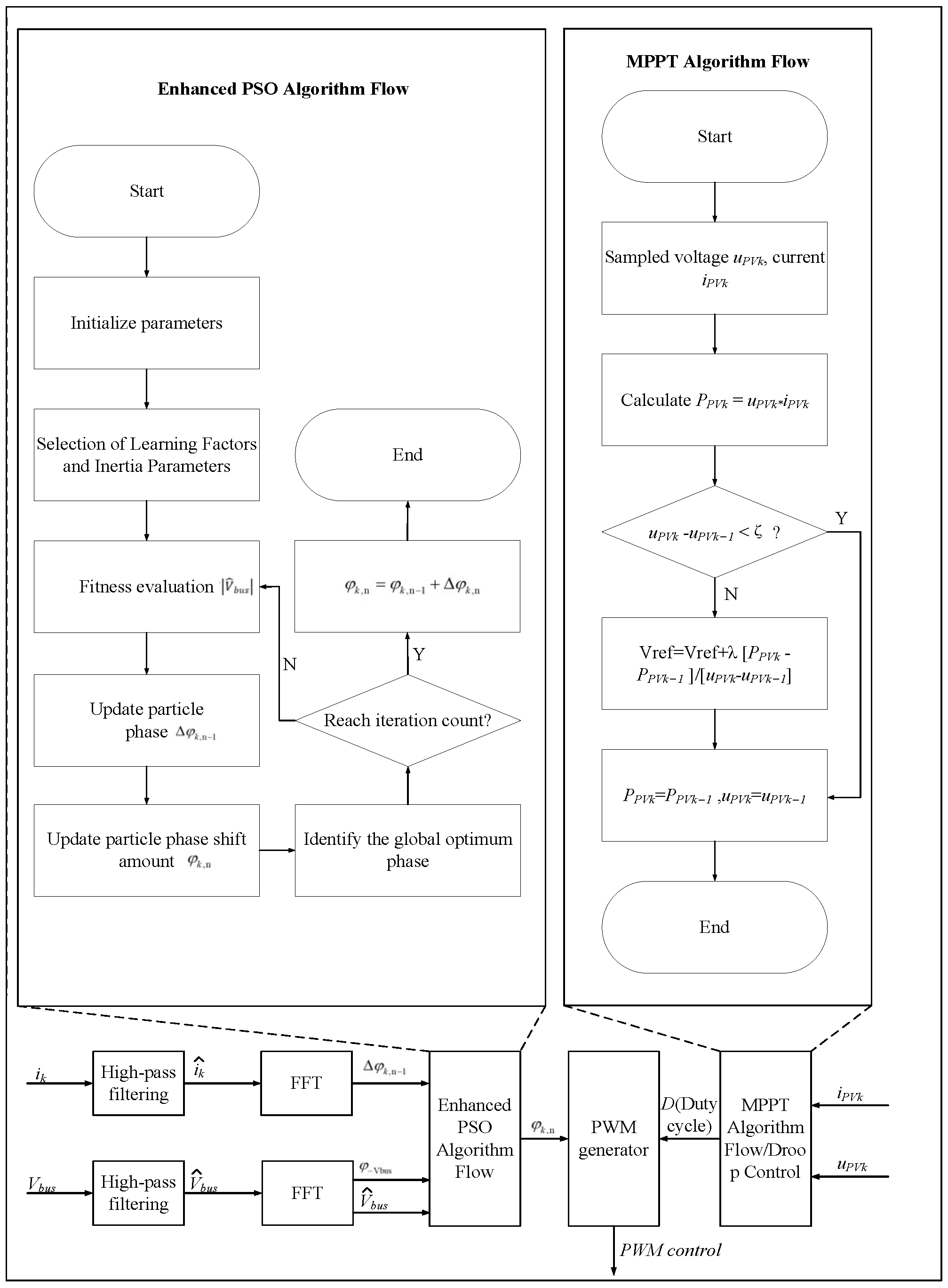
The final system control block diagram is shown in Figure 3 (Taking a system of four converters as an example). The effectiveness of the proposed algorithm will be verified in Section 3 through Simulink simulations, focusing on four key metrics: steady-state ripple suppression rate, convergence speed, stability under load step changes, and plug-and-play adaptability. The simulation parameters (e.g., circuit components, PSO coefficients)are detailed in Table 1 and Table 2 to ensure reproducibility. The parameters of the PSO and the enhanced PSO are completely consistent, with only the optimization code being different.
Figure 3.
Control Block Diagram of Phase-Shift-Based Ripple Suppression.
Table 1.
Control Algorithm Parameters.
Table 2.
Circuit Parameters.
To ensure stable and cooperative convergence among multiple converters without inter-converter communication, the proposed algorithm introduces random coefficients , , and in each iteration. This stochastic update mechanism avoids the problem that all converters adjust phases synchronously while keeping their phase differences unchanged, which would prevent the system from reaching the global optimum. Driven by the random disturbance and the unified objective of minimizing bus voltage ripple, all converters can eventually converge cooperatively to the near-optimal phase solution.
3. Simulation Results and Discussion
In this section, the effectiveness and stability of the proposed controller are validated. It is noted that the output voltage amplitude may undergo significant variations during the plug-and-play operations of multiple parallel-connected photovoltaic units. Since the primary focus of the converter control is to verify ripple suppression performance, a droop-based voltage stabilization method is applied in the simulation to facilitate clear observation of the ripple characteristics. PV modules are modeled with MPP voltage 29 V, MPP current 7.35 A (Table 2), and their input irradiance is set to 1000 W/m2 (25 °C)with fluctuations to simulate real-world non-uniform condition. The parameters of the components and algorithms used in this study are listed in the table.
3.1. Comparison of Steady-State Ripple Amplitude
Four DC-DC converters were connected in parallel, and the ripple magnitude was compared under conditions with and without the controller applied.
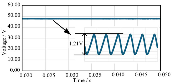
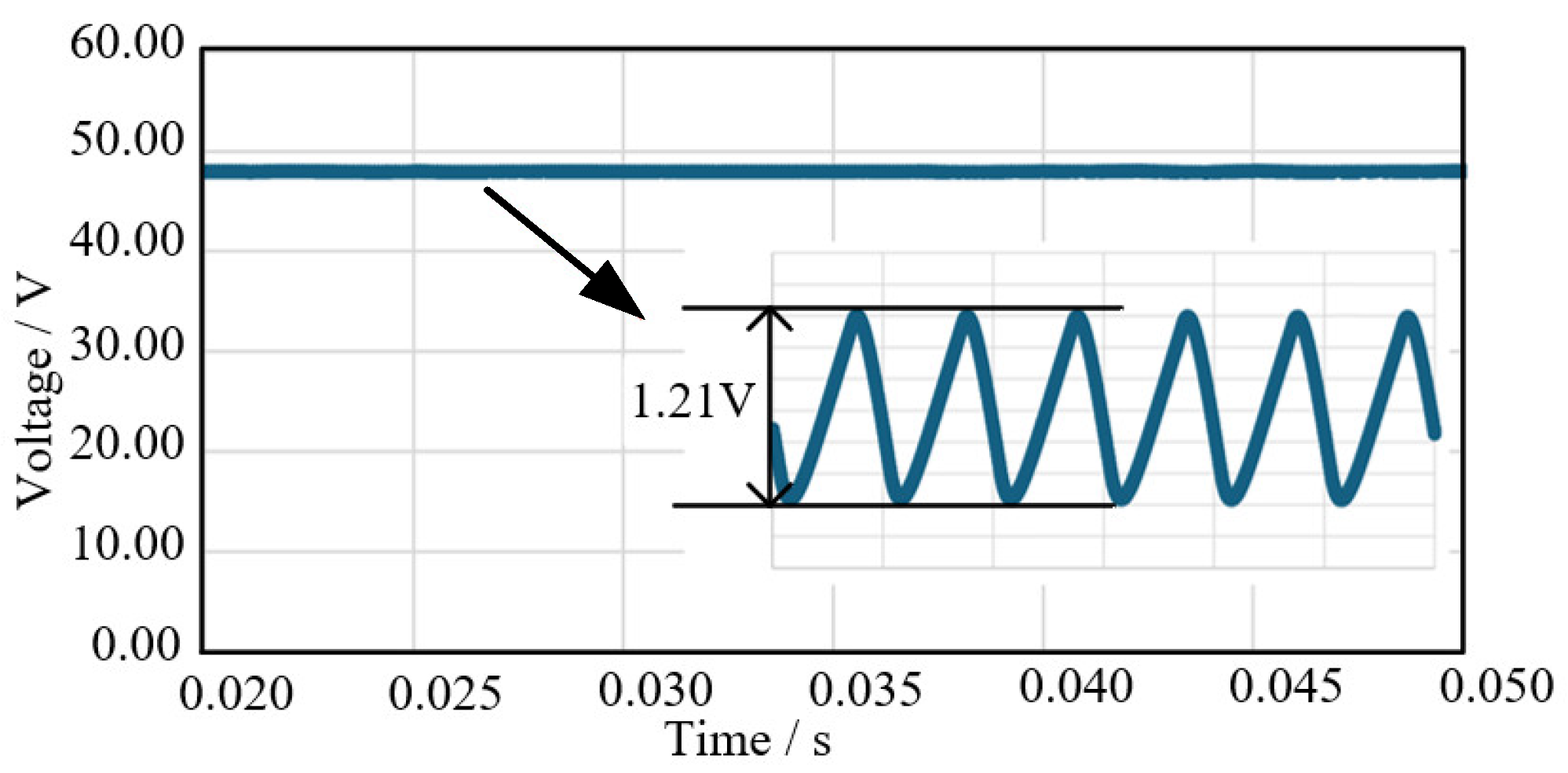
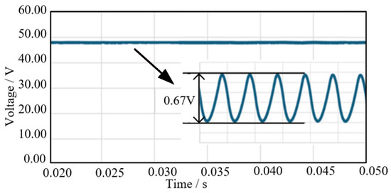
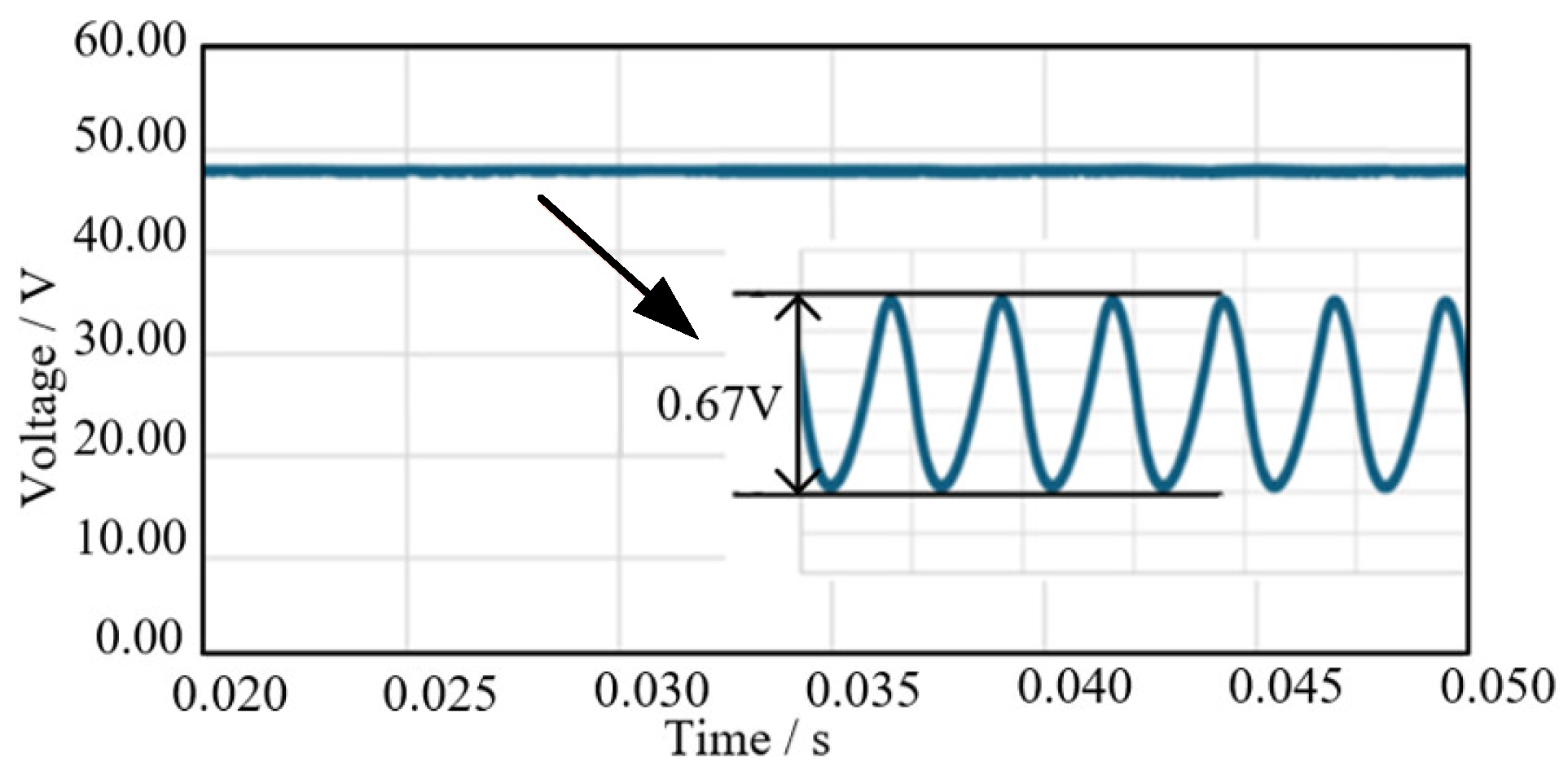
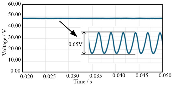
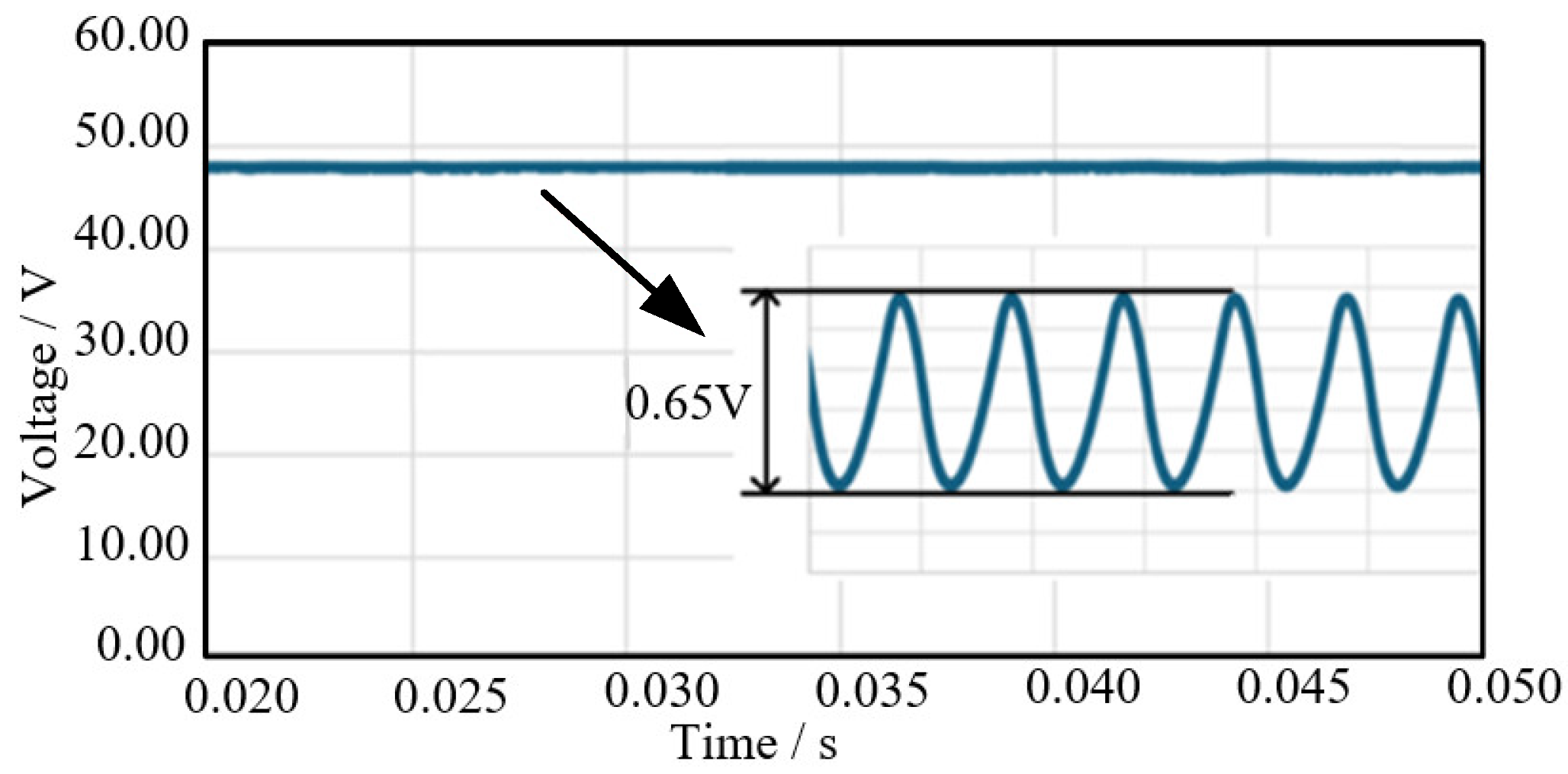
As shown in Figure 4, Figure 5 and Figure 6, when no control system was implemented, the input phases of the converters were random, leading to significant bus voltage ripple. After applying the control system, the output bus ripple was effectively suppressed. Prior to activating the controller, the steady-state bus ripple measured 1.21 V. With the controller enabled, the steady-state ripple was reduced to 0.65–0.67 V, achieving approximately 53% suppression compared to the uncontrolled case.
Figure 4.
Without Controller.
Figure 5.
Ripple suppression capability of the PSO Algorithm Control.
Figure 6.
Ripple suppression capability of the Improved Phase-Shift Control.
It is noteworthy that both the standard PSO algorithm and the proposed control algorithm exhibited comparable ripple suppression performance. This similarity arises because the PSO algorithm also essentially searches for solutions near the phase opposite to the bus ripple, resulting in analogous optimization outcomes.
However, unlike in DC-DC converters where ripple can be reduced to very low levels, the residual ripple in this photovoltaic-based system persists due to variations in the amplitude of the PV inputs. Unlike ideal identical DC sources, the non-uniform input characteristics prevent the theoretical cancellation of ripple to zero. Even with optimally interleaved phases, a certain amount of ripple remains inevitable.
3.2. Convergence Speed
The simulation verified the effectiveness of the control method, demonstrating a significant reduction in ripple. As mentioned earlier, although exhaustively traversing all phase combinations or directly using the PSO algorithm to optimize the entire phase range could also achieve the optimal solution, the proposed algorithm first narrows down the range of the optimal solution and then further refines it, thereby reducing the time required to reach the minimum ripple.
Four DC-DC converters were connected in parallel, and both the conventional PSO algorithm and the improved PSO algorithm were applied.
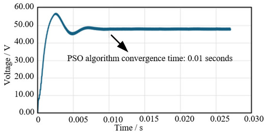
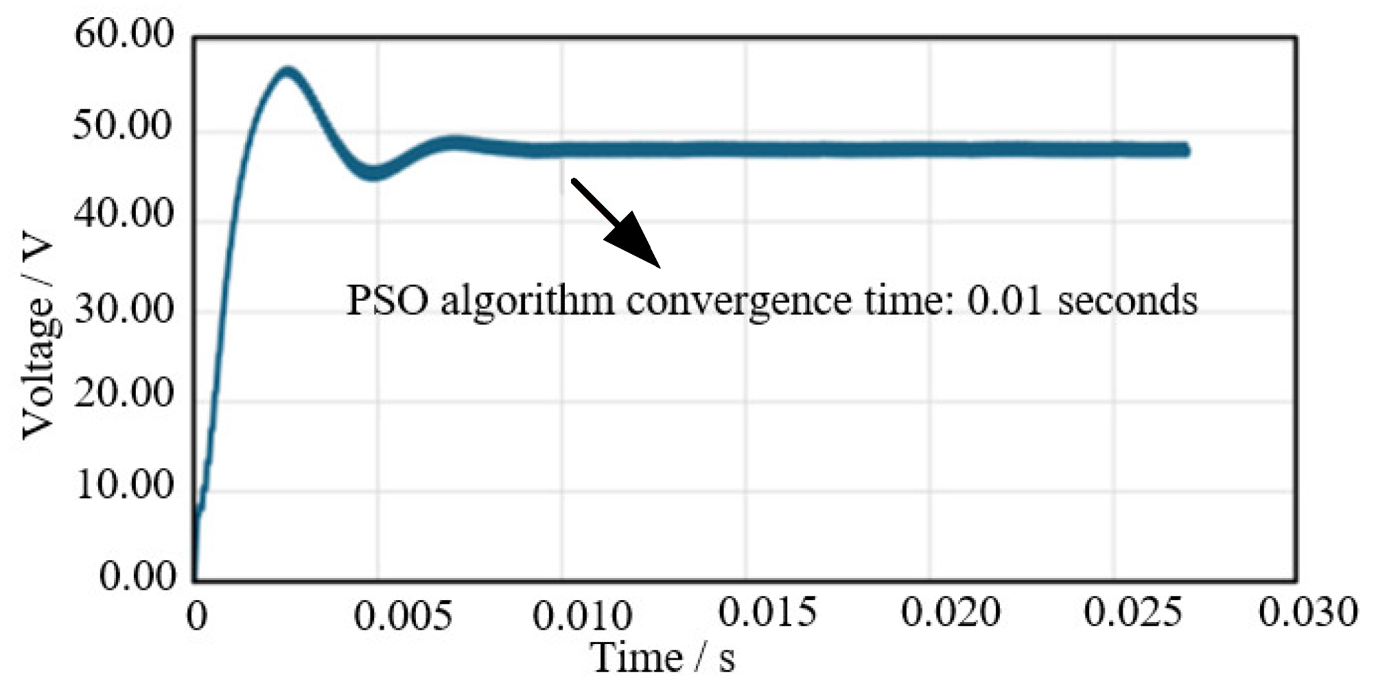
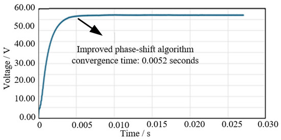
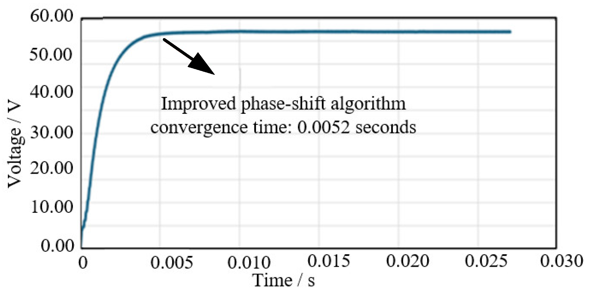
As shown in Figure 7 and Figure 8, it can be observed that the conventional PSO algorithm reached a steady state at approximately 0.010 s (10 ms), at which point the bus voltage stabilized. In contrast, the improved PSO algorithm achieved a similar steady state at around 0.0052 s (5.2 ms). This difference arises because the conventional PSO must optimize over the entire 0–360° phase range, resulting in slower convergence to the optimal solution. When no controller is applied, the PWM output remains a fixed signal, making the concept of convergence speed irrelevant; thus, it is not included in the comparison.
Figure 7.
Convergence speed of the PSO Algorithm Control.
Figure 8.
Convergence speed of the Improved Phase-Shift Control.
Furthermore, no local optimum phenomenon was observed in this case. However, the improved PSO algorithm can early identify the region containing the global optimum, thereby assessing the quality of solutions within its vicinity. In contrast, the conventional PSO lacks the ability to evaluate nearby solutions, which could lead to convergence to a local optimum under different conditions.
3.3. Load Step Change
After verifying the effectiveness of the improved PSO algorithm in suppressing ripple within the photovoltaic grid-connected system, its stability performance was further validated. In this test, the bus load was adjusted to observe the convergence behavior of the system. The load is sequentially reduced to 0.5 Ω at 0.3 s and 0.2 Ω at 0.7 s. The results are shown in Figure 9.
Figure 9.
Load Step Change.
Here it can be observed that during the load step change, the system returns to a stable operating condition after a transient period of approximately 3 ms. As previously discussed, the inductor currents from individual converters superimpose on the common bus. Therefore, the change in load resistance does not affect the position of the optimal solution itself. This enables the converters to rapidly reconverge to the original optimal operating point. The change in the ripple magnitude is primarily due to the fact that the inductor currents generate voltage across the bus load—thus, variations in load inevitably affect the amplitude of the voltage ripple.
3.4. Converter Plug-and-Play Characteristics
In this method, as the converters do not communicate with each other, the optimal operating point shifts when a converter is plugged in or removed. Consequently, each converter autonomously readjusts its phase until the system reconverges to the new optimal solution. Converter 2 plugged in at t = 0.01 s, Converter 3 plugged in at t = 0.02 s, Converter 4 plugged in at t = 0.03 s; each plug-in event triggers a phase re-optimization
As shown in Figure 10, during the instant of converter plug-in or removal, the optimal phase solution for each converter changes. However, the phases of the remaining three converters initially remain unchanged, causing a sudden increase in bus voltage ripple. The control strategy quickly adjusts the phases of the converters, reducing the ripple again and restoring stability after a transient period of approximately 5 ms.
Figure 10.
Converter Plug-and-Play Characteristics.
It is noteworthy that when the number of converters increases from one to two, the bus ripple is significantly reduced due to the interleaving effect. However, as the system further scales to three and four converters, although it continues to converge rapidly, the overall bus ripple does not decrease notably and even exhibits a slight increase. This occurs because, in multi-converter photovoltaic parallel systems, the input conditions of individual converters are non-uniform. As a result, even under ideal operating conditions, the ripple does not fully cancel to zero. Thus, although the control strategy achieves the optimal solution, some residual ripple remains and may vary with system configuration.
3.5. Carrier Frequency Variation
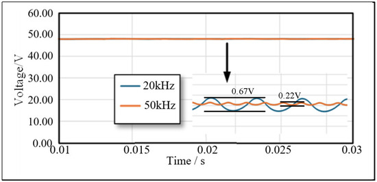
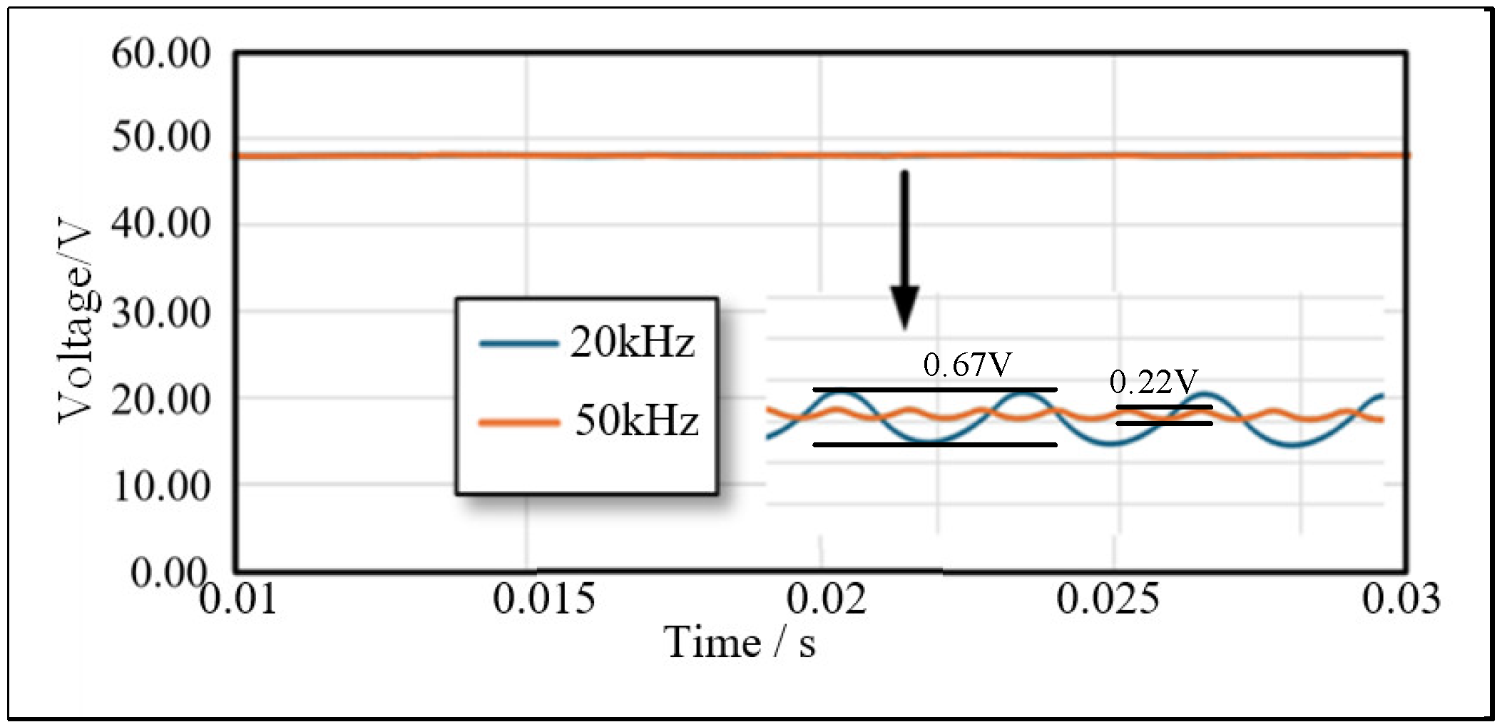
As shown in Figure 11, the results of varying the carrier frequency indicate that the bus ripple amplitude changes accordingly. References [16,21] have previously utilized frequency modulation techniques for ripple suppression. However, it should be emphasized that frequency variation does not interfere with the phase-shift-based ripple suppression mechanism proposed in this method. The controller maintains its effectiveness and demonstrates notable stability even under changes in operating frequency.
Figure 11.
Carrier Frequency Variation.
3.6. Result Comparison
In this section, we define the Ripple Suppression Performance as the ratio of the ripple value obtained using the corresponding control strategy to the ripple value obtained without using that strategy. It can be observed that a smaller value of this ratio indicates better ripple suppression effectiveness of the control strategy.
For instance, Reference [22] achieves a bus ripple reduction to 0.14 V, demonstrating significantly better ripple suppression performance compared to the method proposed in this paper. However, this approach is only applicable to converters with identical input sources. In contrast, due to varying amplitudes of photovoltaic inputs in our system, theoretical ripple cancellation to zero is unattainable—unlike in converters with uniform DC inputs. Even with optimally interleaved phases, certain residual ripple remains unavoidable.
Reference [23] addresses ripple suppression in parallel-connected PV converters, achieving suppression rates between 58% and 87%. While its best-case performance is similar to ours, this method requires exhaustive traversal of all phase combinations. Although the convergence time is not explicitly stated in the reference, it is theoretically slower.
Reference [15] achieves approximately 43%ripple suppression but necessitates communication among converters, introducing practical limitations.
Reference [24] employs a full-range PSO algorithm for phase optimization, attaining 46%ripple suppression—lower than the results achieved by our method. Moreover, this study does not evaluate convergence speed, though theoretically, optimizing over the entire phase range would lead to convergence rates similar to those in Reference [25]. The specific results are summarized in Table 3, structured as follow.
Table 3.
Performance Comparison of Different Controllers.
4. Experimental Verification
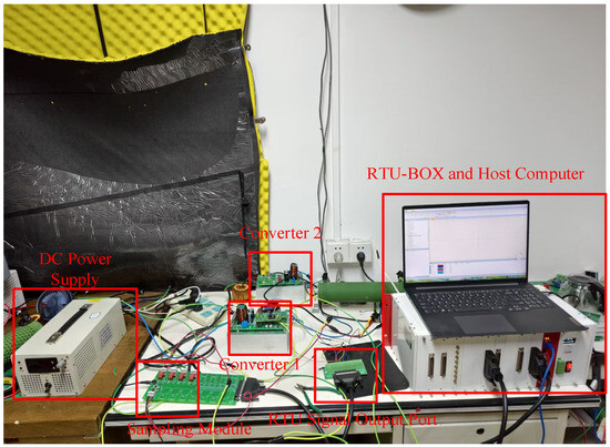
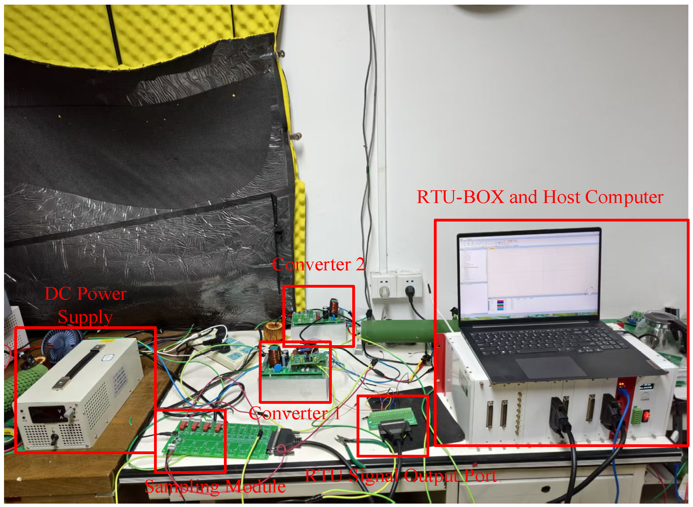
To verify the effectiveness of the proposed method, an experimental circuit is built using the RTU-BOX platform in this paper. The experimental platform is shown in Figure 12.
Figure 12.
Hardware experimental platform based on RTU-BOX.
The RTU-BOX is a real-time simulation and control platform that can be seamlessly integrated with the Simulink environment. It enables direct acquisition of real-time electrical signals such as the current and voltage of the converters, transmits the collected data to the Simulink model for algorithm processing, and then outputs control parameters including duty cycle and phase shift to the power circuit. This design realizes the closed-loop control of the converter system without relying on traditional DSP hardware, which greatly simplifies the experimental implementation process and improves the efficiency of algorithm verification. In the experiment, two Boost converters are connected in parallel, and the hardware parameters of the experiment are shown in Table 4.
Table 4.
Experimental parameters of the parallel converter system.
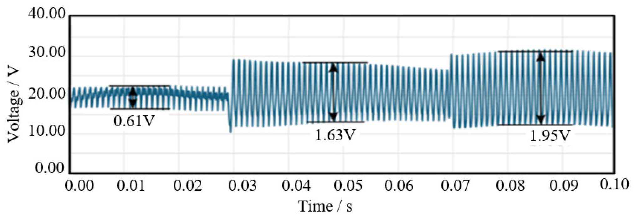
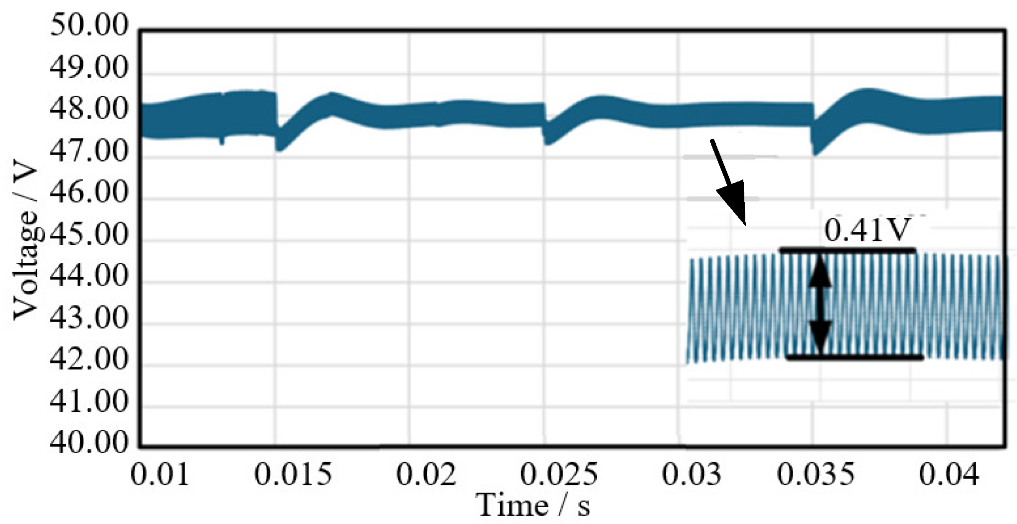
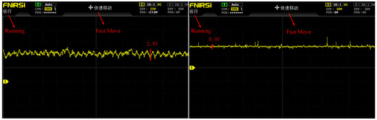
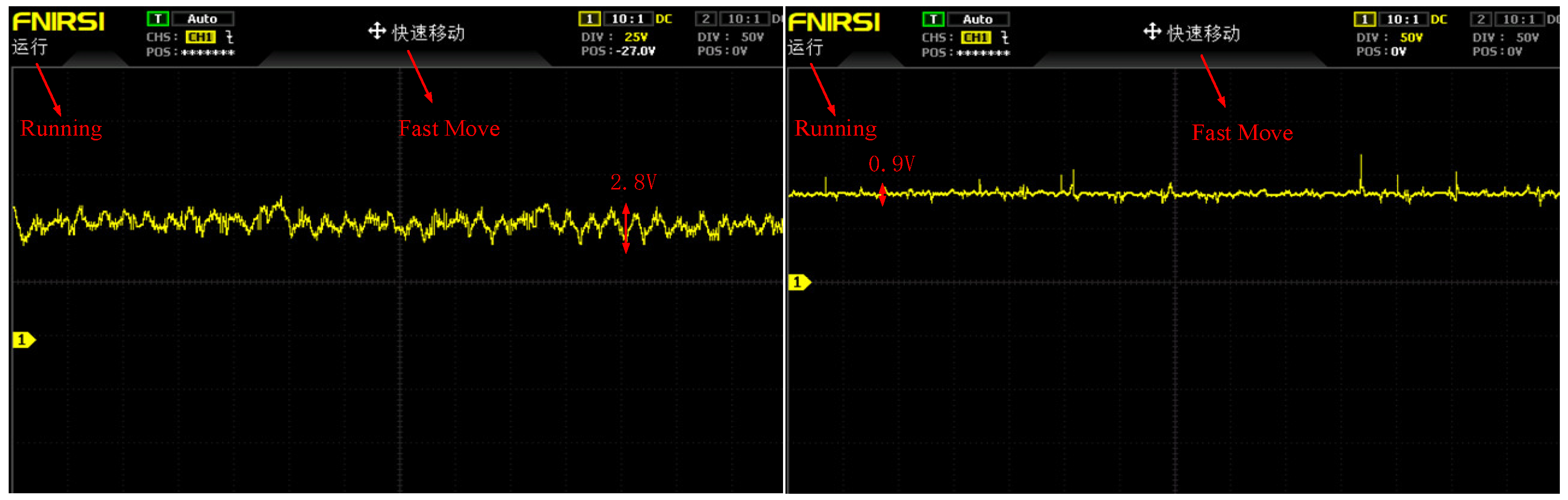
The experimental results are shown in Figure 13:
Figure 13.
Steady-state DC bus voltage waveforms with and without the proposed method. (left) Steady-state DC bus voltage waveform without the proposed method enabled; (right) Steady-state DC bus voltage waveform with the proposed method enabled.
In this chapter, the effectiveness of the proposed communication-free phase-shift ripple suppression method is verified through hardware experiments based on the RTU-BOX platform. A parallel system consisting of two Boost converters is constructed, and the steady-state performance of the method is tested under heterogeneous operating conditions. The experimental results show that, compared with the uncontrolled condition, the proposed method can significantly reduce the DC bus voltage ripple, with the steady-state ripple amplitude reduced from 2.8 V to 0.9 V, which is consistent with the simulation conclusions. The RTU-BOX real-time control platform realizes the closed-loop control of the converter system without relying on traditional DSP hardware, which simplifies the experimental implementation process and verifies the feasibility of the method in practical applications. The experimental results fully demonstrate that the proposed method has excellent ripple suppression performance and practical application value in parallel PV distributed converter systems.
5. Conclusions
This study investigates parallel-connected photovoltaic converter systems and proposes a communication-free ripple suppression strategy. Despite the promising simulation results, this study has two limitations: first, validation is limited to Boost converters and lacks experimental verification; second, only the dominant harmonic component (n = 1) is considered, and higher-order harmonics may affect performance under extreme conditions.
The main contributions are as follows: First, the principle of ripple control through phase-shift manipulation is elucidated, and a PSO-based method is introduced to identify near-optimal solutions under heterogeneous converter parameters. Second, an enhanced PSO algorithm is developed to constrain the search space to a promising region before refinement, significantly accelerating convergence. The proposed method can be applied to distributed converters, where each unit adjusts its phase autonomously in a communication-free manner. Third, simulations performed in Simulink verify the effectiveness of the approach and its rapid optimization capability compared to conventional PSO, along with demonstrated stability under load transients and converter plug-and-play scenarios.
While validation remains simulation-based, future work will include experimental implementation. Further research will focus on: first, extending the proposed method to Buck and Buck-Boost converters, and verifying its performance in a hardware-in-the-loop (HIL) test platform, despite its general theoretical applicability; second, expanding harmonic suppression to higher-order components beyond the dominant harmonic considered in this study, and developing a multi-harmonic optimization objective function that integrates both dominant (n = 0) and higher-order (n = 1, 2) harmonics, further reducing residual ripple.
Author Contributions
Conceptualization, Y.J. and Q.F.; methodology, Y.J. and Q.F.; software, Y.J.; validation, B.W.; writing—review and editing, B.W.; writing—review and editing, M.A. All authors have read and agreed to the published version of the manuscript.
Funding
This work is supported by the National Natural Science Foundation of China (72342006), Sichuan Province Science and Technology Plan: 2024ZHCG0073, the Open Fund of the State Key Laboratory of High-Efficiency and High-Quality Conversion for Electric Power (2024KF002), Guangdong Basic and Applied Basic Research Foundation (2024A1515011059), Zhuhai Industry University Research Project: 2220004002754, Huizhou Science and Technology Plan: 2023BQ010006.
Data Availability Statement
The data presented in this study are available within the article.
Conflicts of Interest
The authors declare no conflicts of interest.
References
- Qi, J.; Huang, X.; Ye, B.; Zhou, D. PV Array Reconfiguration Based on the Shaded Cells’ Number for PV Modules. CSEE J. Power Energy Syst. 2023, 9, 733–742. [Google Scholar]
- Ertekin, D. A High Gain Switched-Inductor-Capacitor DC-DC Boost Converter for Photovoltaic-Based Micro-Grid Applications. CSEE J. Power Energy Syst. 2024, 10, 2398–2410. [Google Scholar]
- Badapanda, M.K.; Tripathi, A.; Upadhyay, R.; Lad, M. High Voltage DC Power Supply with Input Parallel and Output Series Connected DC-DC Converters. IEEE Trans. Power Electron. 2023, 38, 6764–6768. [Google Scholar] [CrossRef] [Scilit]
- Ge, Y.; Hu, H.; Chen, J.; Wang, K.; He, Z. Real-time Power Flow Control Strategy for Electric Railway FTSSs Integrated with PVs and ESSs. CSEE J. Power Energy Syst. 2025, 11, 623–636. [Google Scholar]
- Chen, Y.-Y.; Chang, Y.-C.; Wei, C.-L. Mixed-Ripple Adaptive On-Time Controlled Non-Inverting Buck-Boost DC-DC Converter with Adaptive-Window-Based Mode Selector. IEEE Trans. Circuits Syst. II Express Briefs 2022, 69, 2196–2200. [Google Scholar] [CrossRef] [Scilit]
- Wang, F.; Xu, J.; Li, G. A cascaded multi-port converter with energy storage units for large-scale photovoltaic systems. CSEE J. Power Energy Syst. 2025, 1–11. [Google Scholar] [CrossRef]
- Zhu, Y.; Ohyama, K. An Improved Quadratic Boost Converter with Lower Input Current Ripple and Reduced Power Components for Fuel Cell Systems. IEEE Access 2025, 13, 138733–138744. [Google Scholar] [CrossRef] [Scilit]
- Zhao, H.; Chu, H.; Zhu, X.; Guo, Y. Synthesis and Design of Shunt Resonator-Based Phase Shifters with Reduced Phase Error and In-Band Magnitude Ripple. IEEE Trans. Circuits Syst. I Regul. Pap. 2024, 71, 3064–3073. [Google Scholar] [CrossRef] [Scilit]
- Ren, Q.; Xiao, F.; Liu, J.; Chen, P.; Zhu, Z. Efficiency Improvement and High-Performance Control of Dual-Active-Bridge DC-DC Converter with Triple-Phase-Shift Modulation. CSEE J. Power Energy Syst. 2024, 10, 2434–2445. [Google Scholar]
- Gupta, A.; Korada, N.; Ayyanar, R. Quadratic-Extended-Duty-Ratio Boost Converters for Ultra High Gain Application with Low Input Current Ripple and Low Device Stress. IEEE Trans. Ind. Appl. 2023, 59, 938–948. [Google Scholar] [CrossRef] [Scilit]
- Dasohari, M.; Vishwanathan, N.; Porpandiselvi, S.; Vani, A.R.M. A Soft-Switched Boost Converter Based LED Driver with Reduced Input Current Ripple. IEEE Access 2024, 12, 45904–45922. [Google Scholar] [CrossRef] [Scilit]
- Hata, K.; Tanaka, S.; Ashikaga, T.; Rikiishi, Y. Ripple Reduction and Efficiency Improvement of Always-Dual-Path Hybrid DC-DC Converter Based on Phase Shift Operation. In Proceedings of the 2025 IEEE Applied Power Electronics Conference and Exposition (APEC), Atlanta, GA, USA, 16–20 March 2025; IEEE: New York, NY, USA, 2025; pp. 2284–2289. [Google Scholar]
- Zhang, X.; Huang, A.Q. A novel distributed control and its tolerance analysis for microprocessor power management. In Proceedings of the Twenty-First Annual IEEE Applied Power Electronics Conference and Exposition, APEC’06, Dallas, TX, USA, 19–23 March 2006; IEEE: New York, NY, USA, 2006; p. 7. [Google Scholar]
- Liu, C.; Wang, X.; Ren, Y.; Wang, X.; Zhang, J. A Novel Distributed Secondary Control of Heterogeneous Virtual Synchronous Generators via Event-Triggered Communication. IEEE Trans. Smart Grid 2022, 13, 4174–4189. [Google Scholar] [CrossRef] [Scilit]
- Schuck, M.; Pilawa-Podgurski, R.C.N. Ripple Minimization Through Harmonic Elimination in Asymmetric Interleaved Multiphase DC–DC Converters. IEEE Trans. Power Electron. 2015, 30, 7202–7214. [Google Scholar] [CrossRef] [Scilit]
- Sinha, M.; Poon, J.; Johnson, B.B.; Rodriguez, M.; Dhople, S.V. Decentralized Interleaving of Parallel-connected Buck Converters. IEEE Trans. Power Electron. 2018, 34, 4993–5006. [Google Scholar] [CrossRef] [Scilit]
- Kacimi, N.; Idir, A.; Grouni, S.; Boucherit, M.S. Improved MPPT Control Strategy for PV Connected to Grid Using IncCond-PSO-MPC Approach. CSEE J. Power Energy Syst. 2023, 9, 1008–1020. [Google Scholar]
- Dholey, M.K.; Sinha, D. EEMR-PSO-CUCKOO: Energy Efficient MANET Routing Using Hybrid PSO and CUCKOO Search. J. Mob. Multimed. 2025, 21, 729–748. [Google Scholar] [CrossRef] [Scilit]
- Chafi, S.-E.; Balboul, Y.; Fattah, M.; Mazer, S.; El Bekkali, M. Novel PSO-Based Algorithm for Workflow Time and Energy Optimization in a Heterogeneous Fog Computing Environment. IEEE Access 2024, 12, 41517–41530. [Google Scholar] [CrossRef] [Scilit]
- Fernandez-Martinez, J.L.; García-Gonzalo, E.; Fernández-Alvarez, J. Theoretical analysis of particle swarm trajectories through a mechanical analogy. Int. J. Comput. Intell. Res. 2008, 4, 93–105. [Google Scholar] [CrossRef] [Scilit]
- Saleh, H.; Mostafa, S.; Ismail, A.H.; Srivastava, S.; Alsamhi, S.H. Swin-PSO-SVM:A Novel Hybrid Model for Monkeypox Early Detection. IEEE Access 2024, 12, 187367–187385. [Google Scholar] [CrossRef] [Scilit]
- Dutta, S.; Johnson, B. A Practical Digital Implementation of Completely Decentralized Ripple Minimization in Parallel-Connected DC–DC Converters. IEEE Trans. Power Electron. 2022, 37, 14422–14433. [Google Scholar] [CrossRef] [Scilit]
- Yang, H.; Fu, Q.; Wang, B.; Chen, Y.; Su, Y. Communication-Free Interleaving Control of Parallel-Connected DC-DC Converters. Electronics 2023, 12, 2111. [Google Scholar] [CrossRef] [Scilit]
- Sadeghi, Z.; Bauman, J. Variable Phase-Shift Switching Strategy For Multi-Input Interleaved Boost Converters in Solar Energy Systems. In Proceedings of the 2024 IEEE Transportation Electrification Conference and Expo (ITEC), Chicago, IL, USA, 19–21 June 2024; IEEE: New York, NY, USA, 2024; pp. 1–6. [Google Scholar]
- Liu, X.; Zhuo, S.; Huangfu, Y.; Wang, S.; Bai, H.; Ma, R. Ripple Suppression of Multi-Phase Converter under Switch Fault for Fuel Cell Application Based on Phase Shift Reconfiguration. In Proceedings of the 2024 IEEE Transportation Electrification Conference and Expo (ITEC), Chicago, IL, USA, 19–21 June 2024; IEEE: New York, NY, USA, 2024; pp. 1–6. [Google Scholar]

Disclaimer/Publisher’s Note: The statements, opinions and data contained in all publications are solely those of the individual author(s) and contributor(s) and not of MDPI and/or the editor(s). MDPI and/or the editor(s) disclaim responsibility for any injury to people or property resulting from any ideas, methods, instructions or products referred to in the content. |
© 2026 by the authors. Licensee MDPI, Basel, Switzerland. This article is an open access article distributed under the terms and conditions of the Creative Commons Attribution (CC BY) license.