


Abstract
This paper presents two broadband four-way power dividers based on a novel T-coil topology, operating in the 22–32 GHz band (covering the K/Ka bands). Type I adopts a cascaded power division structure, while Type II employs a direct-feed integrated architecture. The innovation lies in the introduction of isolating capacitors at the input and output ports, which significantly shortens the critical transmission line lengths in both topologies. This effectively reduces the equivalent inductance and raises the self-resonant frequency, achieving wideband response while maintaining structural simplicity, compact size, and ease of integration. Both circuits were fabricated using a standard 45 nm CMOS process. The measured core chip areas (excluding pads) are only 0.125 mm2 for Type I and 0.066 mm2 for Type II, demonstrating excellent integration density. Through even-mode and odd-mode theoretical analysis and full-wave electromagnetic simulation verification, both power dividers exhibit good impedance matching and port isolation across the target frequency band. Measurement results further confirm their performance: across the entire 22–32 GHz band, both power dividers achieve a return loss better than 11 dB and isolation exceeding 15 dB; the insertion loss is 1.1–1.4 dB for Type I and 0.8–1.3 dB for Type II; the amplitude imbalance is below ±0.3 dB and ±0.1 dB, respectively; and the phase imbalance is less than ±5° and ±3°, respectively. All measured data show good agreement with simulation results. In summary, Type I offers advantages in layout flexibility and isolation performance, while Type II excels in insertion loss and chip size. Both provide practical circuit solutions for broadband, high-performance, and compact power division systems.
1. Introduction
Power dividers are key passive components in multi-channel feed networks of microwave and millimeter-wave systems, and they are widely used in phased-array radar, satellite communications, and 5G/6G mobile communication systems [1,2,3]. As systems evolve toward millimeter-wave frequencies, power dividers face more stringent broadband performance requirements: they must simultaneously achieve low insertion loss, high isolation, good amplitude and phase consistency, and compact size over a wider frequency band [4].
Conventional Wilkinson power dividers (WPDs) are limited by their narrowband characteristics [5]. Although techniques such as differential structures [6], multi-section impedance transformers [7], artificial transmission lines [8], multi-coupled inductors [9], and lumped elements [10] can effectively extend the bandwidth, these methods are often accompanied by increased size or structural complexity. Moreover, at millimeter-wave frequencies, they face challenges such as sharply increased loss and sensitivity to fabrication tolerances [11]. Most of the aforementioned studies are based on improvements to the traditional Wilkinson topology. Exploring novel power divider topologies that can achieve broadband, high-efficiency, and miniaturized performance in the millimeter-wave band has become a research frontier and hotspot.
In recent years, design approaches based on lumped elements or hybrid distributed/lumped elements have demonstrated unique advantages. Among these, the T-coil structure was initially widely used in high-speed integrated circuits to extend amplifier bandwidth and was later introduced into microwave passive circuit design. Leveraging its excellent broadband impedance transformation and parasitic compensation capabilities, the T-coil topology provides a new pathway for enhancing power divider performance [12,13,14]. This structure can effectively increase the circuit’s self-resonant frequency and has already demonstrated ultra-wideband performance in the Ku/K bands [15,16,17,18]. For example, reference [19] applied the T-coil structure to the isolation network of a two-way power divider, improving the isolation bandwidth by incorporating an L-R||C-L matching network. However, existing research has mostly focused on two-way power dividers, while the exploration of T-coil power dividers with higher division ratios (e.g., four-way) operating in higher frequency bands (such as the K/Ka band) remains insufficient. A four-way power divider holds direct application value in constructing four-element phased-array subsystems, but its design complexity is significantly higher. Maintaining good isolation and amplitude/phase balance among the output ports under broadband conditions presents a greater challenge [20,21,22].
Based on the above background, to address the urgent need for high-performance, compact four-way power dividers in Ka-band and adjacent frequency broadband systems, this paper proposes an isolation capacitor structure based on the T-coil topology. By strategically optimizing the electromagnetic field distribution at key nodes, the required physical transmission line length is significantly shortened, achieving a “short-path” structural design. This approach not only reduces insertion loss but also effectively enhances the self-resonant frequency. Building on this concept, this paper further designs, implements, and compares two types of four-way power dividers: Type I employing a cascaded division scheme and Type II employing a direct division scheme. Both designs achieve a synergistic optimization of miniaturization, low loss, and broadband performance across the 22–32 GHz frequency range.
In our previous work [23], we primarily carried out simulation analysis on the T-coil based four-way power divider. As an extension of that study, the core innovations of this paper are reflected in the following three aspects: First, by introducing isolation capacitors at the input and output ports, we significantly shorten the critical transmission line lengths in both topologies and apply this improved structure for the first time to two distinct Ka-band four-way power divider architectures (cascaded Type I and direct Type II). Second, we derive the complete S-parameter formulas for both topologies, providing reusable closed-form design models that address the lack of theoretical derivation in our prior work. Third, we conduct on-chip measurements under the same process (45 nm RFE) and frequency band (22–32 GHz), clarifying through measured data the engineering trade-offs among isolation, area, and insertion loss for the two topologies. The effectiveness of the design is thoroughly validated through even-odd mode theoretical analysis, full-wave electromagnetic simulation, and fabricated chip measurements. Experimental results show that both power dividers exhibit an insertion loss of less than 1.5 dB, a return loss better than 11 dB, isolation higher than 15 dB, and amplitude and phase imbalances controlled within ±0.3 dB and ±5°, respectively. Type I demonstrates advantages in layout flexibility and isolation performance, while Type II shows superiority in insertion loss and miniaturization.
2. Theoretical Analysis
2.1. Cascaded Four-Way Power Divider
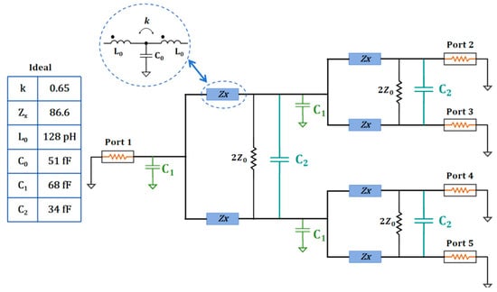
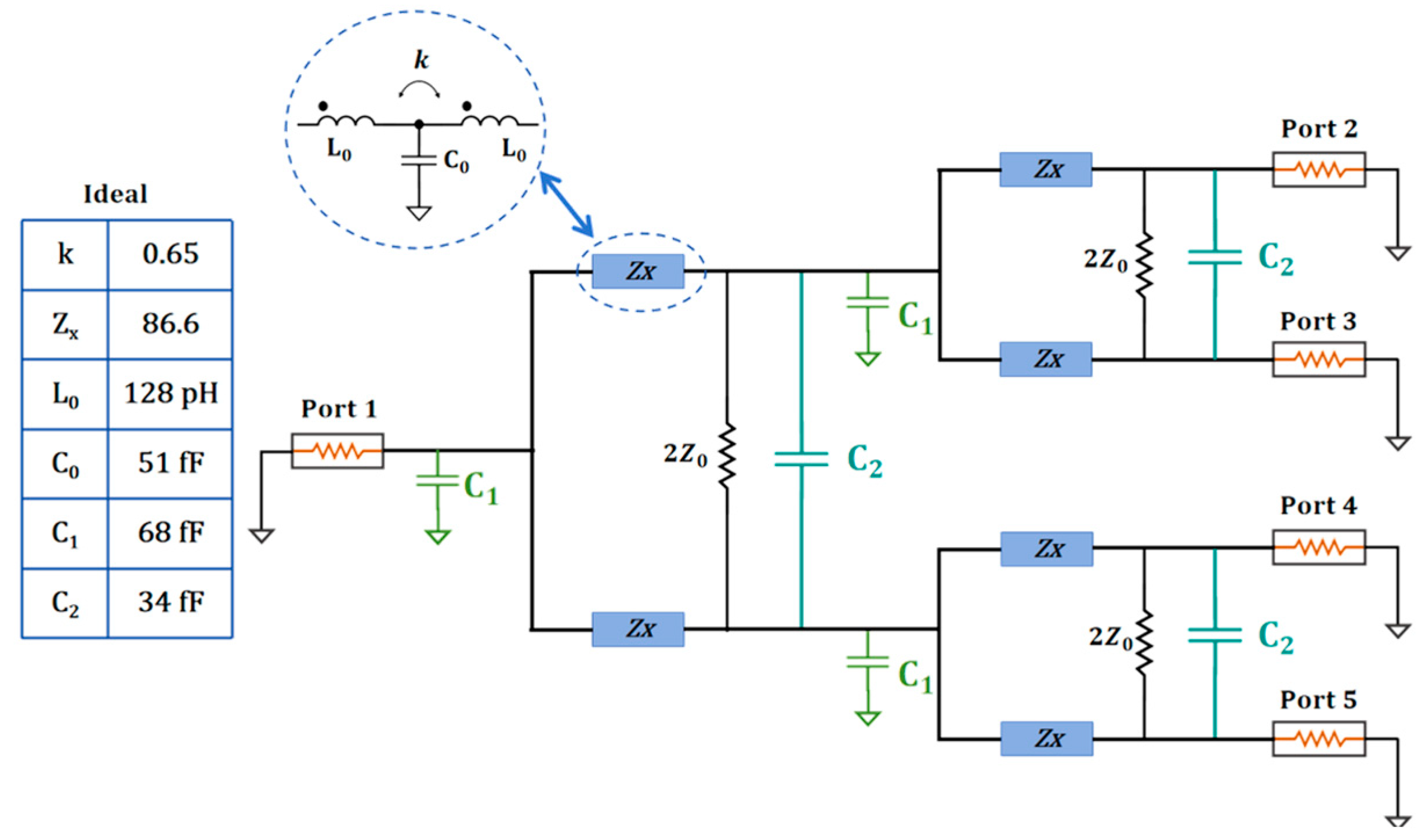
Figure 1 shows the circuit diagram of the proposed cascaded four-way power divider, which employs a hierarchical design approach. The input signal is first equally split into two paths by a primary 1-to-2 power divider. Each path is then further divided by an independent secondary 1-to-2 power divider, ultimately producing four output signals with matched amplitude and phase. This modular and stage-by-stage configurable structure provides significant advantages in microwave systems that require high isolation, layout flexibility, and ease of integration.
Figure 1.
Circuit diagram of the proposed Type I WPD topology.
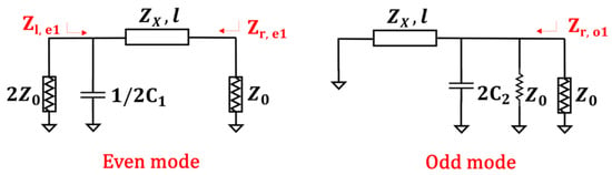
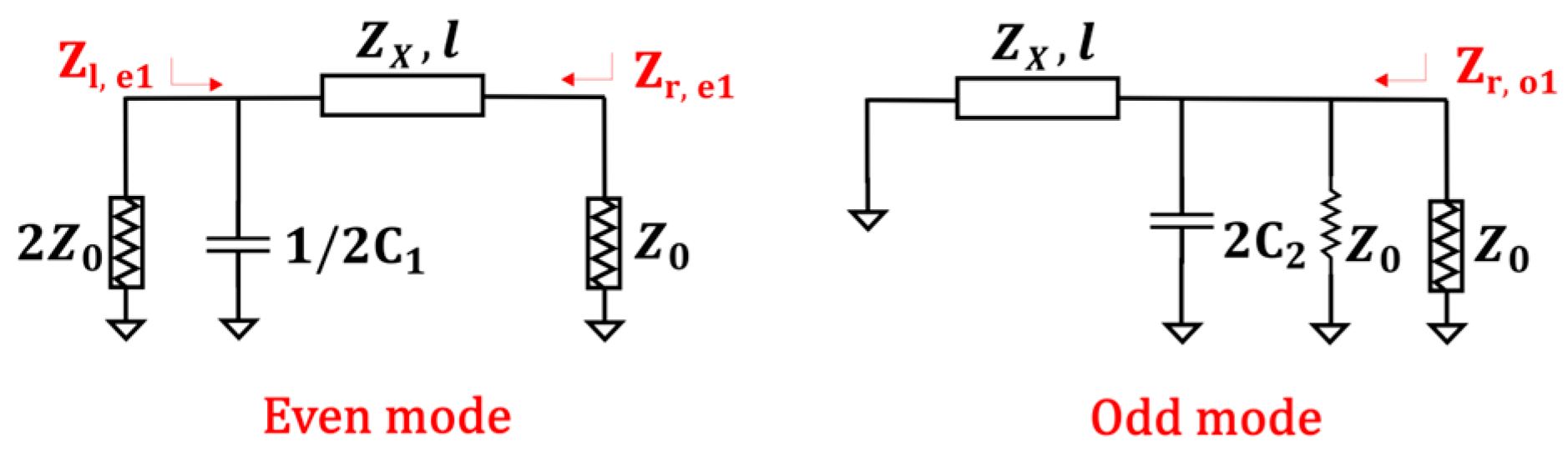
As shown in Figure 2, since the Type I WPD T-coil topology is composed of two identical two-way T-coil topologies in cascade, its even-mode and odd-mode analysis can be simplified to that of a single two-way WPD T-coil topology.
Figure 2.
Even-mode and odd-mode equivalent circuits of a two-way power divider.
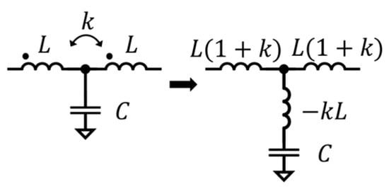
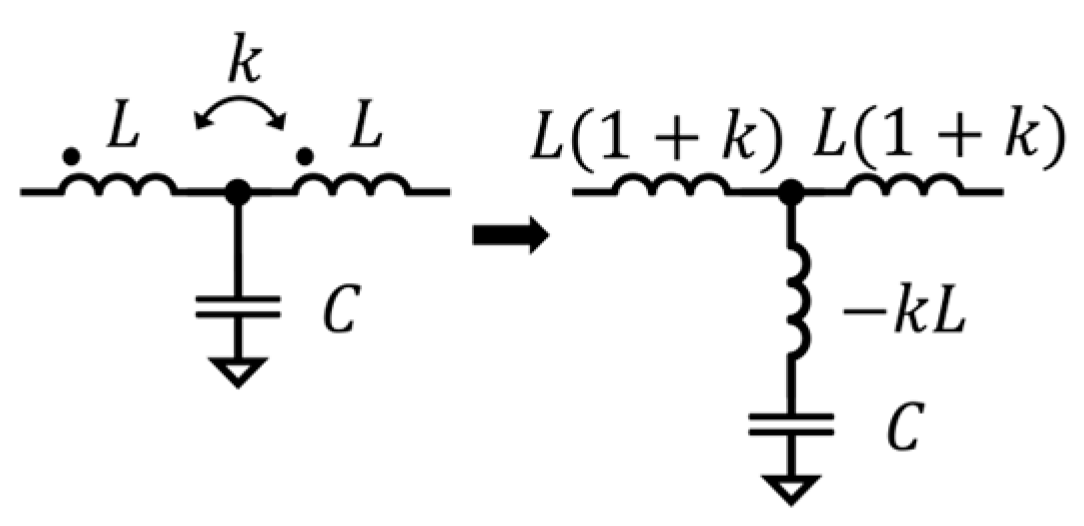
In the millimeter-wave band, the electrical length θ of a transmission line is a core design parameter, defined as θ = β·l. Here, β = 2π/λ is the phase constant (with λ being the wavelength), representing the phase shift per unit length, and l is the physical length of the transmission line. To achieve circuit miniaturization and compensate for parasitic effects, this paper introduces a T-coil structure, as shown in Figure 3, to equivalently replace traditional distributed transmission lines. Specifically, by incorporating an isolation capacitor for parasitic compensation, the physical length of the originally equivalent quarter-wavelength transmission line is significantly reduced. To maximize the use of this characteristic for miniaturization, all subsequent design derivations in this paper are based on a new transmission line length of one-eighth wavelength (i.e., βl = 45° or π/4).
Figure 3.
Equivalent circuit of the T-coil.
After determining the equivalent model of the core branching unit, this paper employs the even-odd mode analysis method (as shown in Figure 2) to further investigate the matching and isolation characteristics of the circuit. Under even-mode excitation, the symmetry plane can be considered an open circuit due to the absence of current flow. At this point, a compensation capacitor C1 needs to be introduced at the input port to satisfy the matching condition in the even mode. Based on the even-mode input impedance Zr,e1 (defined as the impedance seen from the right side of the first stage) derived from the transmission line equations (as shown in Equations (1) and (2)), to achieve ideal matching over a wide bandwidth (i.e., Zr,e1 = Z0), the value of the compensation capacitor C1 can be determined. This capacitor serves to cancel the parasitic reactance of the inductor at high frequencies, thereby maintaining impedance consistency. In odd-mode operation, the input signal exhibits asymmetric characteristics, causing current to flow through the isolation resistor and capacitor. Here, the introduction of capacitor C2 enhances the isolation between ports, effectively reducing mutual interference between the output ports. Based on reference [13] and our previous work [23], the formulas for relevant component parameters of this structure have been established and are detailed as follows.
To achieve ideal matching within the operating frequency band, Zr,e1 = Z0, the calculation formula for the branch impedance Zx in Figure 2 is derived as follows:
Because
when odd-mode matching is achieved, Zr,o1 = Z0, the capacitance C2 can be obtained:
To ultimately characterize the S-parameters of the entire network, the reflection characteristics of the internal nodes need to be accurately described. Therefore, the even-mode input impedance Zl,e1 looking from the left side of the first stage, as well as the even-mode and odd-mode input impedances Zr,e1 and Zr,o1 looking from the right side of the first stage, can be expressed as:
Due to the nested symmetry of the cascaded structure, after analyzing the local isolation of a single stage, it is necessary to further determine the cross-group isolation performance through global even-odd mode analysis. The global even-mode input impedance Zl,e1global (seen from the left side of the first stage) and the global odd-mode input impedance Zl,o1global (also seen from the left side) are introduced to evaluate the isolation between non-adjacent ports. Their expressions are as follows:
The corresponding S-parameter formulas can be obtained from Equations (9)–(13), Among these parameters, the input return loss S11 and insertion loss S21 are determined by the superposition of even-odd mode transmission characteristics. For a four-way power divider, in addition to the adjacent-port isolation S23, the cross-group isolation S24 is also a key performance metric. Due to the cascaded structure, the process of signal returning to the first stage and then propagating to the other side is relatively complex; consequently, the performance of S24 highly depends on the isolation capability of the first-stage dividing unit.
In the initial design stage, with a coupling coefficient of k = 0.65, a center frequency of f0 = 27 GHz, and a transmission line electrical length l = λ/8 (i.e., 45°) at the center frequency, theoretical calculations were performed based on Equations (1)–(18). The resulting key parameters, as annotated in Figure 1, are Zx = 86.6 Ω, L0 = 128.17 pH, C0 = 51.04 fF, C1 = 68.08 fF, C2 = 34.04 fF. Under these design conditions, the theoretical insertion loss S21 at the center frequency of 27 GHz is approximately −6 dB (corresponding to the four-way power division loss), while the calculated input/output return loss (S11, S22) and port-to-port isolation (adjacent ports S23, cross-group ports S24) are all better than 15 dB.
2.2. Direct Four-Way Power Divider
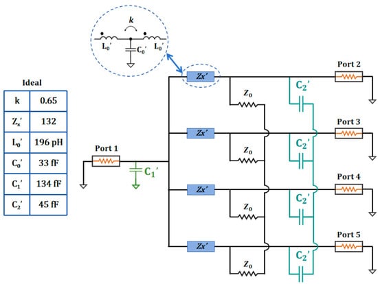
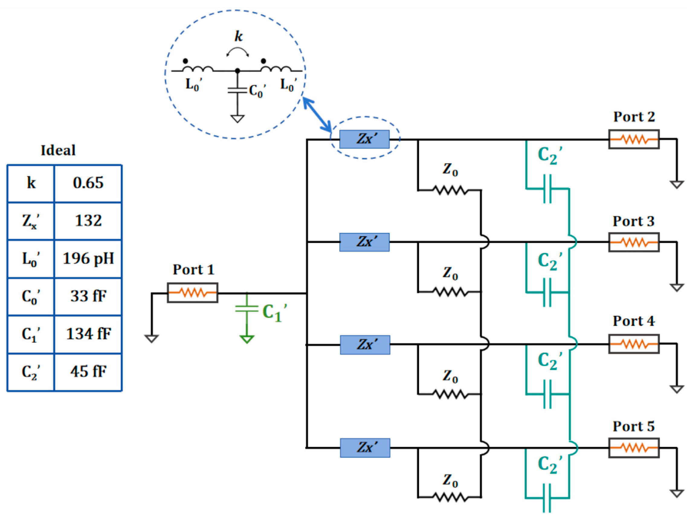
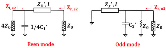
As shown in Figure 4, the direct four-way power divider adopts an integrated central-node design concept, where the input signal is simultaneously and directly coupled to four output branches through a shared broadband matching network, achieving single-stage synchronous power division. This topology avoids the cascaded loss and phase accumulation introduced by multi-stage division. With its strictly symmetric layout and equal electrical path lengths, it offers key advantages in microwave systems that prioritize low excess loss and compact circuit layout. The even-odd mode equivalent structure of this circuit is illustrated in Figure 5, which serves as the foundation for the subsequent even-odd mode analysis.
Figure 4.
Circuit diagram of the proposed Type II WPD topology.
Figure 5.
Even-mode and odd-mode equivalent circuits of a four-way power divider.
As shown in Figure 2 and Figure 5, even-mode and odd-mode analysis of the Type I and Type II WPD T-coil topologies reveals that their odd-mode matching structures are identical, while the sole difference in the even-mode matching structure lies in whether the matching is performed from 2 Z0 to Z0 or from 4 Z0 to Z0.
According to prior work [23], the formulas for relevant component parameters of this structure have been established and are detailed as follows.
To ultimately characterize the S-parameters of the entire network, the reflection characteristics of the internal nodes need to be accurately described. Therefore, the even-mode impedance looking from the left side (Zl,e2), the even-mode impedance looking from the right side (Zr,e2), and the odd-mode impedance looking from the right side (Zr,o2) can be expressed as:
Similarly, based on the impedance expressions of each branch, the S-parameter matrix describing the overall performance of the device can be constructed as follows.
Based on the design conditions of a coupling coefficient k = 0.65, a center frequency f0 = 27 GHz, and a transmission line electrical length l = λ/8 (i.e., 45°) at the center frequency, theoretical calculations were performed according to Equations (19)–(30). The obtained key parameters are labeled in Figure 4: Zx′ = 132.29 Ω, L0′ = 195.83 pH, C0′ = 33.41 fF, C1′ = 133.71 fF, C2′ = 44.57 fF. Under these design conditions, the theoretical insertion loss S21 at the center frequency of 27 GHz is approximately −6 dB (corresponding to four-way power division loss), and the calculated input/output return losses (S11, S22) as well as the port-to-port isolations (S23, S24) are all better than 11 dB.
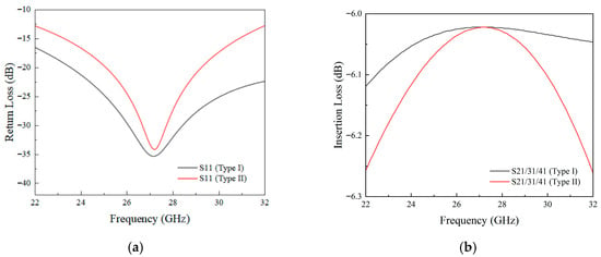
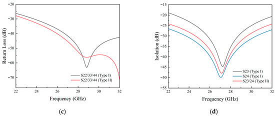
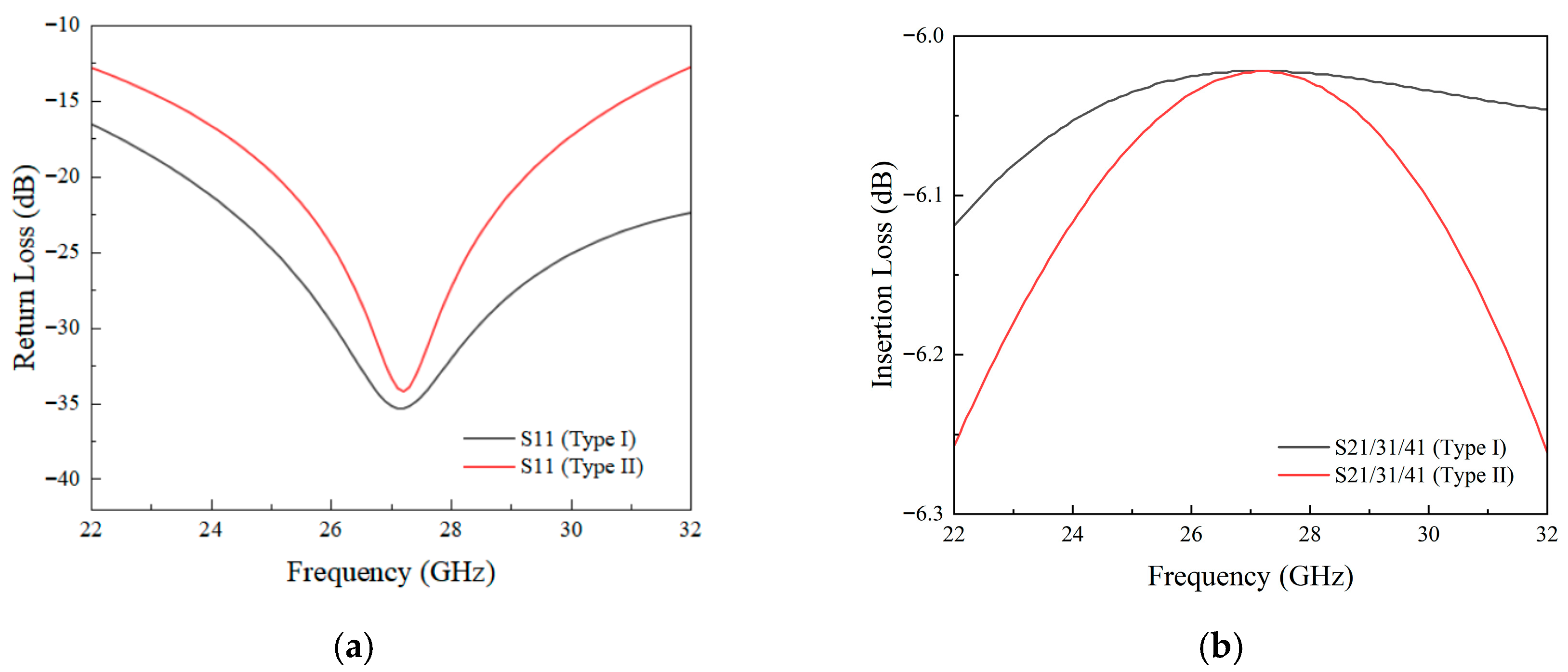
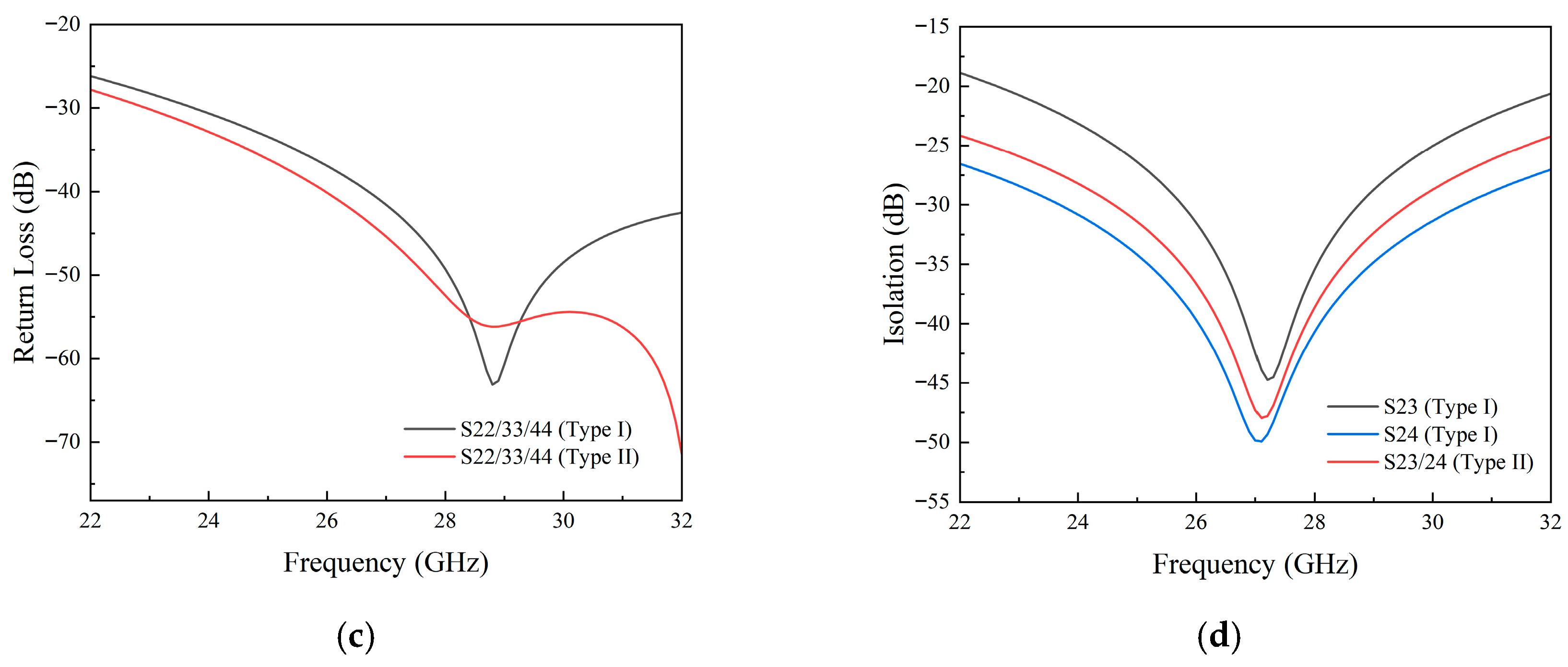
Figure 6 presents a comparison of the curves for Type I and Type II configurations based on transmission line theory. It can be observed that Type I exhibits smaller loss fluctuations, indicating superior gain flatness. In the subsequent simulation results, Type I shows slightly higher insertion loss, which is primarily due to its cascaded structure incorporating a larger number of inductors, leading to increased additional losses per stage. Furthermore, the S24 parameter of Type I outperforms S23. This is because the adjacent ports (2–3) are physically closer and share an isolation network, resulting in stronger substrate coupling. In contrast, the non-adjacent ports (2–4) are farther apart and have a grounded structure in between, naturally providing better isolation.
Figure 6.
Comparison of S-parameters between Type I and Type II. (a) S11, (b) S22/33/44, (c) S21/31/41 and (d) S23/24/34.
3. Performance and Design
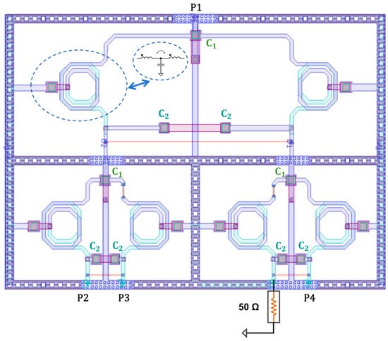
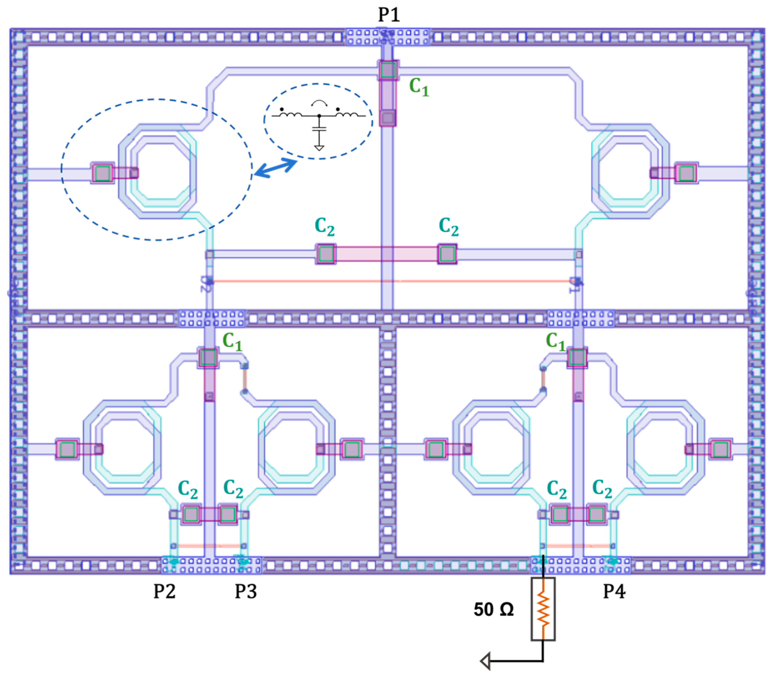
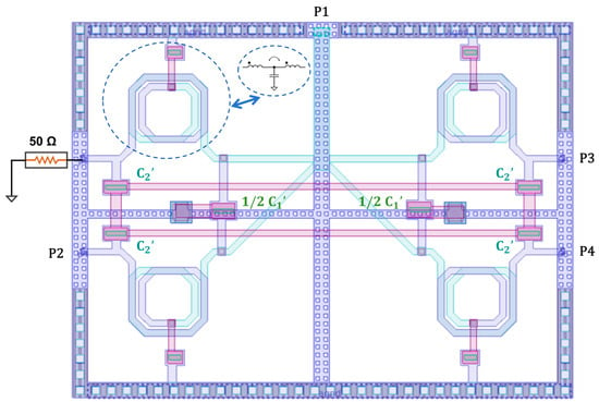
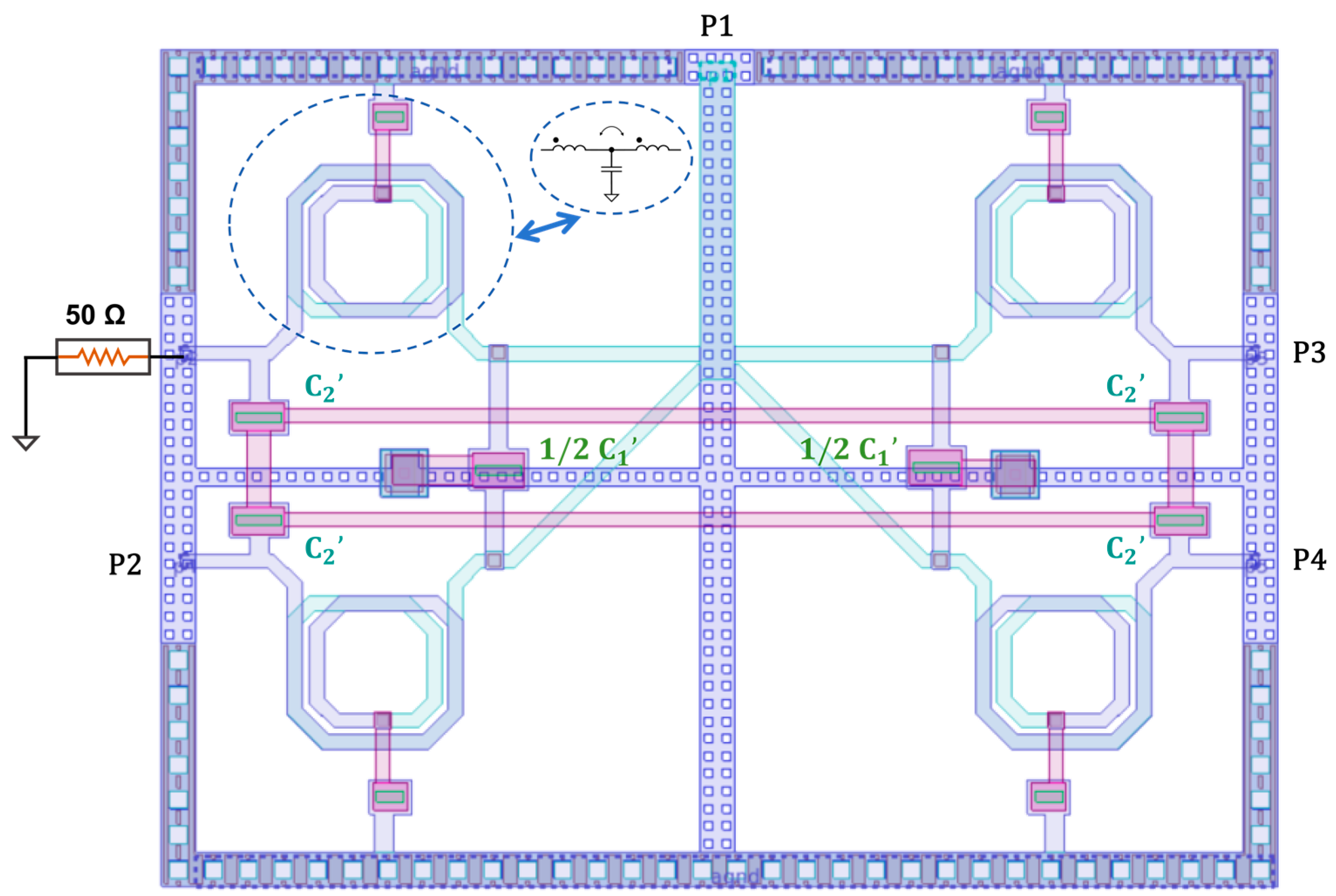
A performance evaluation was conducted for both the cascaded and direct 4-way power divider designs, which were implemented in GlobalFoundries 45RFE technology. The inductors were fabricated using two layers of 3 μm-thick copper metal, and the capacitors were realized as metal-oxide-metal (MOM) capacitors. The layouts of Type I and Type II are shown in Figure 7 and Figure 8, respectively. The full circuit layout was simulated using the electromagnetic simulator (EMX) within the Cadence Virtuoso IC618 software environment.
Figure 7.
The layout of Type I.
Figure 8.
The layout of Type II structure.
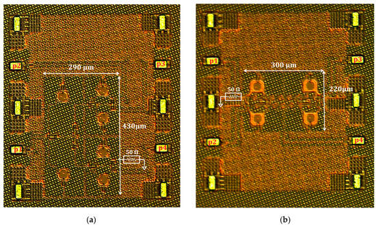
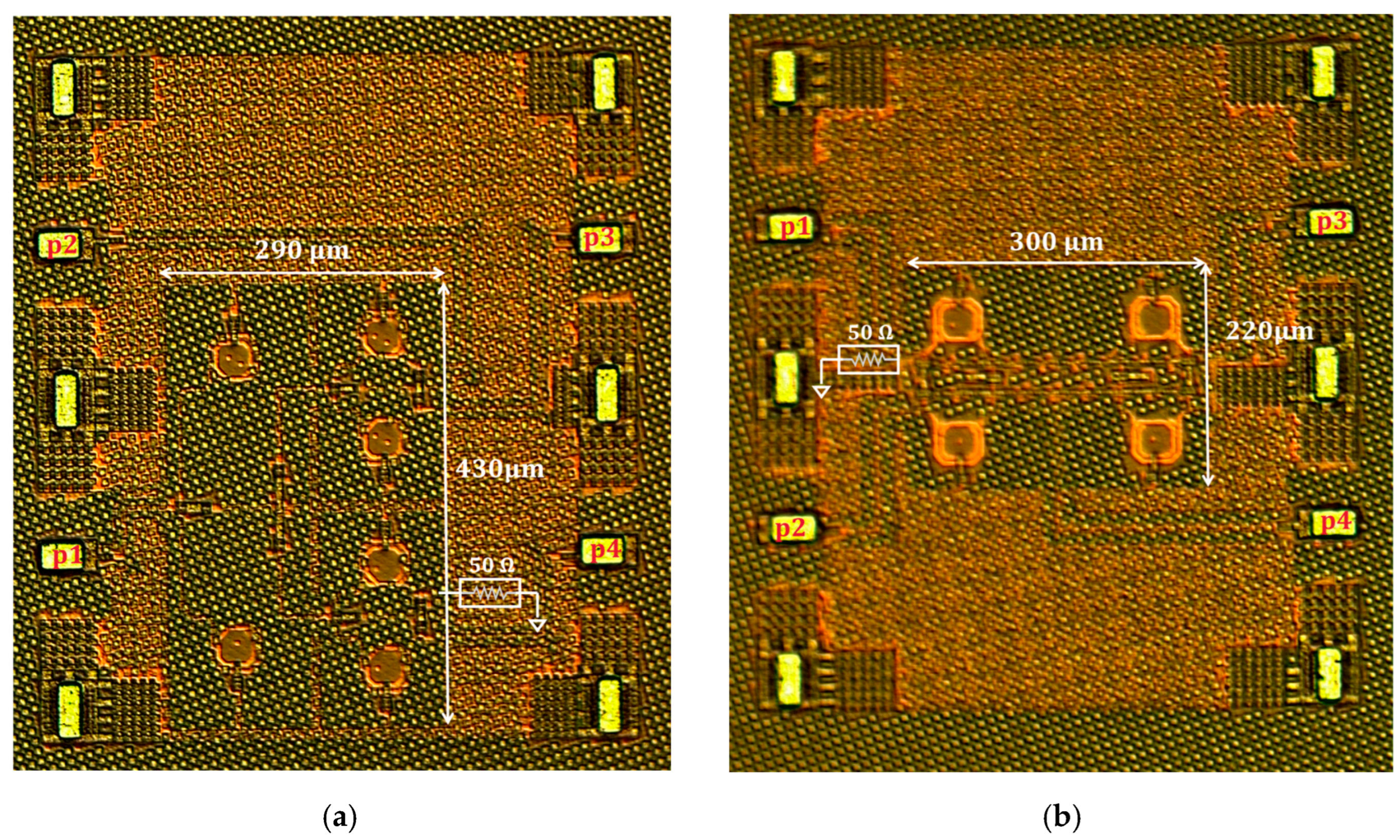
Considering that during testing, the GSGSG-type probe used only supports four signal ports, whereas a 4-way power divider requires a total of five ports (one input and four outputs), one of the output ports (marked in the figure) was terminated with an integrated 50 Ω resistor to ground at the design stage to facilitate on-wafer measurement. Owing to the symmetry of the circuit, the response of this grounded port can be equivalently obtained from the measurement of its symmetric counterpart. For both Type I and Type II structures, the grounded port indicated in the figure is effectively represented by the measured results of its symmetric port P3. To avoid redundant curves, the measurement data for this equivalent port are not repeated in this paper.
In the EMX simulation analysis in Cadence, parasitic effects such as parasitic inductance and parasitic capacitance are taken into account. Therefore, the values of L and C are iteratively adjusted during layout design to achieve optimal results within the target frequency range.
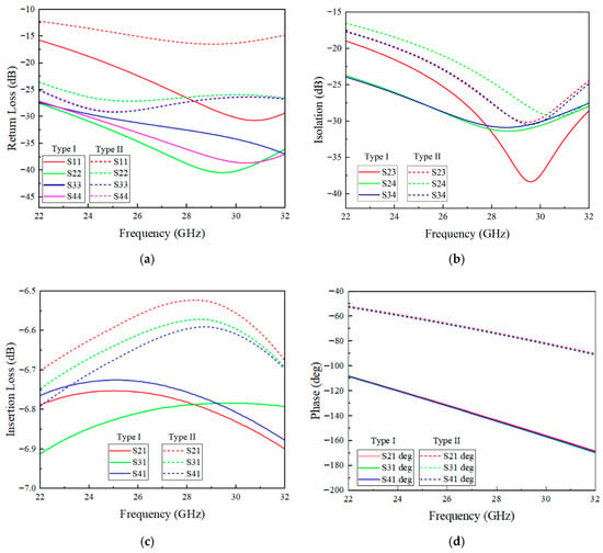
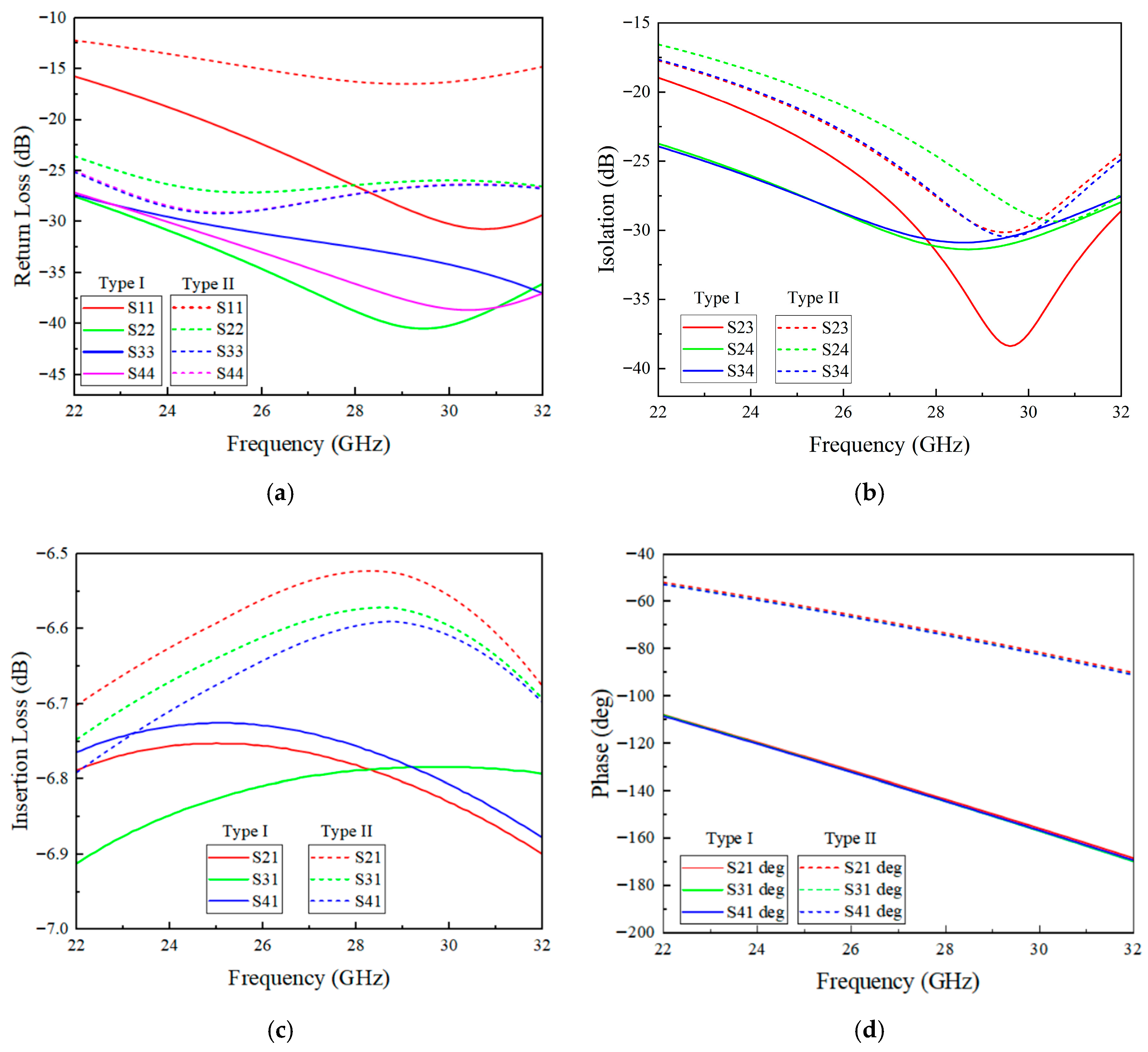
As can be seen from Figure 9, the Type I WPD exhibits a return loss better than 15 dB and isolation exceeding 18 dB across the frequency range from 22 GHz to 32 GHz. The insertion loss ranges from 0.74 dB to 0.92 dB. In comparison, the Type II WPD achieves a return loss better than 11 dB, isolation exceeding 15 dB, and an insertion loss ranging from 0.52 dB to 0.79 dB over the same frequency range. The improved insertion-loss performance of Type II is primarily attributed to the change in the output path from a two-stage to a single-stage output structure.
Figure 9.
Simulated return loss (a) isolation, (b) insertion loss, (c) and phase (d) of Type I and Type II.
4. Measurement Results
To verify the performance of the two proposed T-coil-based four-way power divider designs, both the Type I (cascaded) and Type II (direct) structures were fabricated and characterized on-wafer. The circuits were implemented in the GlobalFoundries 45 nm RFE process and manufactured through a multi-project wafer (MPW) run. Measurements were carried out using a vector network analyzer over the 22–32 GHz band, with the reference plane calibrated to the probe tips via a short-open-load-thru (SOLT) calibration to remove systematic errors introduced by the probes and cables.
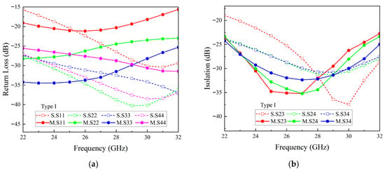
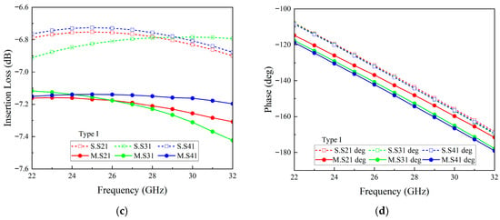
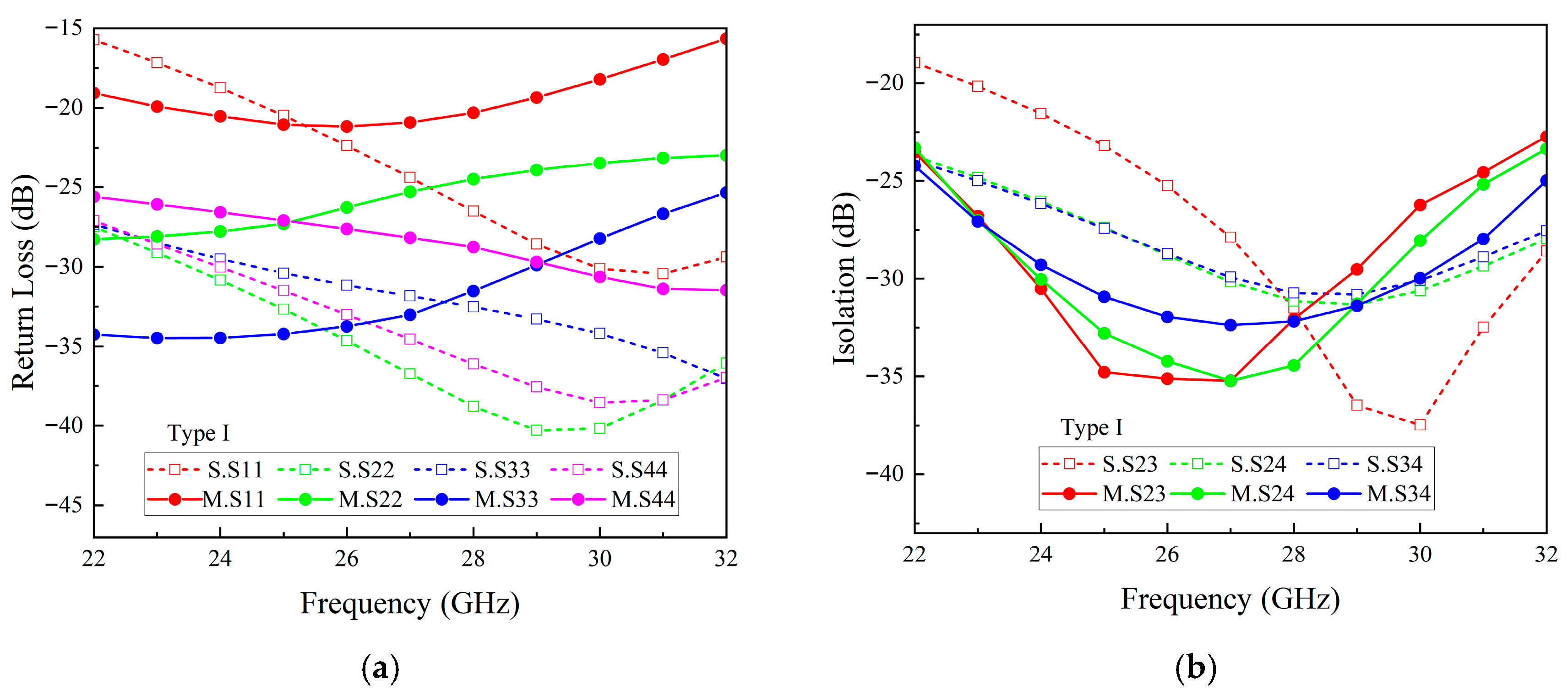
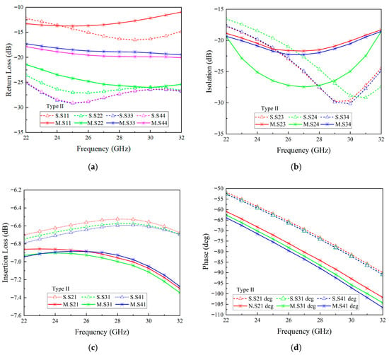
As can be seen from Figure 10, the Type I WPD measures 0.125 mm2, while the Type II WPD occupies 0.066 mm2. Over the frequency range from 22 GHz to 32 GHz, the measured results in Figure 11 show that the Type I WPD exhibits a return loss better than 15 dB, isolation exceeding 20 dB, and an insertion loss ranging from 1.1 dB to 1.4 dB. The phase imbalance is within 5°, and the amplitude imbalance is within 0.3 dB. Under the same frequency range, the measured results in Figure 12 show that the Type II WPD achieves a return loss better than 11 dB, isolation exceeding 15 dB, and an insertion loss ranging from 0.8 dB to 1.3 dB, with a phase imbalance within 3° and an amplitude imbalance within 0.1 dB.
Figure 10.
A microphoto of Type I (a) and Type II (b).
Figure 11.
Measured/simulation return loss (a) isolation, (b) insertion loss, (c) and phase (d) of Type I.
Figure 12.
Measured/simulation return loss (a) isolation, (b) insertion loss, (c) and phase (d) of Type II.
As shown in Figure 11, the measured insertion loss is slightly higher than the simulated values, primarily due to parasitic effects during wafer testing, contact losses at the electrodes, and deviations in the conductivity of metal layers introduced during the actual fabrication process. Additionally, the measured return loss and resonant frequency points exhibit slight shifts, which are closely related to process variations, phase accumulation errors introduced by the cascaded nested structure, and parasitic effects from the testing probes.
Regarding phase imbalance, the measured phase mismatch primarily stems from manufacturing tolerances inherent in the 45 nm CMOS process, as well as phase discrepancies caused by physical length mismatches in the transmission lines. Furthermore, since Type I employs a cascaded configuration, the two-stage circuit accumulates phase errors, resulting in a phase imbalance of approximately ±5°, which is slightly larger than the ±3° observed in the single-stage structure of Type II (as shown in Figure 12). In contrast, the single-stage structure of Type II experiences less phase error accumulation, leading to better suppression of phase imbalance.
Nevertheless, the measured phase imbalance remains within ±5°, and the amplitude imbalance is maintained at approximately 0.3 dB. These results sufficiently validate the robustness and process adaptability of the cascaded T-coil topology in achieving high-performance broadband matching.
Based on the comparative analysis of simulated and measured data, the Type II device demonstrates a solid design foundation within the 22–32 GHz frequency band. The measured and simulated curves show generally consistent trends, with insertion loss maintained between −6.5 and −7.4 dB, phase decreasing linearly with frequency, and return loss generally below −11 dB, indicating that the electromagnetic model and fabrication process are overall reliable. However, certain performance degradations are observed in the measured results, such as insertion loss being approximately 0.3–0.5 dB higher than the simulated values, return loss slightly higher than simulation, and phase values marginally lower. These discrepancies are primarily attributed to additional losses introduced by the surface roughness of metal conductors during actual testing, as well as impedance mismatches caused by contact between the test probes or connectors. Notably, among the theoretically symmetrical isolation metrics, the measured S24 is significantly better than S23 and S34. This phenomenon mainly stems from slight asymmetries in the physical layout, leading to differences in parasitic coupling paths between different ports. Additionally, in the millimeter-wave frequency band, extremely small signal levels are highly sensitive to random errors in the test environment (such as probe pressure, cable bending, and calibration reference plane shifts). These combined factors result in the “unexpectedly” improved isolation characteristics observed for S24.
As shown in Table 1, the two proposed power dividers based on the capacitive-compacted T-coil topology demonstrate significant comprehensive advantages in key performance metrics. In terms of chip integration, among most CMOS implementations in the K/Ka-band, the Type II structure achieves a core area of only 0.066 mm2, which is comparable to the compact size of the design in [8] implemented in a more advanced 28 nm process. Regarding insertion loss, Type II achieves 1.0 ± 0.2 dB, ranking among the best in the table, while its low loss variation (±0.2 dB) ensures excellent gain flatness and transmission efficiency across a wide bandwidth. In terms of bandwidth and matching performance, the proposed design maintains a 37.0% fractional bandwidth while achieving a return loss better than 11 dB. In comparison, although the design in [8] achieves comparable insertion loss, its bandwidth is limited to 22.2%, and it relies on a differential structure requiring additional baluns for single-ended applications. Meanwhile, the design in [6] exhibits wider bandwidth but suffers from larger area and higher insertion loss. In summary, at a center frequency of 27 GHz, the proposed single-ended topologies based on the capacitive-compacted T-coil achieve a desirable trade-off among compact size, low insertion loss, high isolation (>18 dB), and wide bandwidth, demonstrating robust design methodology and strong potential for practical engineering applications. Overall, Type I is preferred for applications demanding high isolation, while Type II is optimal for loss- and area-constrained systems.
Table 1.
Performance comparison of integrated four-way WPDCs.
5. Conclusions
This paper presents two broadband four-way power dividers (Type I: cascaded structure; Type II: direct structure) based on innovative T-coil topologies, operating in the 22–32 GHz band (covering K/Ka bands). By introducing isolation capacitors to shorten transmission lines, equivalent inductance is reduced and self-resonant frequency is improved. Measurement results demonstrate that both designs achieve excellent performance across the target band: insertion loss 1.5 dB, return loss better than 15 dB, amplitude imbalance within ±0.3 dB, phase imbalance within ±5°, and port isolation above 11 dB. Type I offers layout flexibility and high isolation (>20 dB) with a size of 0.125 mm2, while Type II exhibits lower additional loss (0.8–1.3 dB) and a more compact size (0.066 mm2). Both structures are suitable for broadband power-division systems, with Type I being advantageous for high-isolation and modular-integration applications, and Type II excelling in scenarios demanding low loss and a compact layout.
Author Contributions
Conceptualization, Q.Z. and F.W.; Methodology, Q.Z., W.W. and F.W.; Writing—original draft, Q.Z.; Writing—review and editing, X.W. and P.C. All authors have read and agreed to the published version of the manuscript.
Funding
This research was supported by the National Natural Science Foundations of China (Grant No. 92473208).
Data Availability Statement
Data are contained within the article.
Acknowledgments
The authors would like to thank GlobalFoundries for providing silicon fabrication support through the 45RFE UPP program.
Conflicts of Interest
The authors declare no conflicts of interest.
References
- Pozar, D.M. Microwave Engineering, 4th ed.; Wiley: Hoboken, NJ, USA, 2011. [Google Scholar]
- Pi, Z.; Khan, F. An introduction to millimeter-wave mobile broadband systems. IEEE Commun. Mag. 2011, 49, 101–107. [Google Scholar] [CrossRef] [Scilit]
- Hong, W.; Jiang, Z.H.; Yu, C.; Zhou, J.; Chen, P.; Yu, Z.; Zhang, H.; Yang, B.; Pang, X.; Jiang, M.; et al. Multibeam Antenna Technologies for 5G Wireless Communications. IEEE Trans. Antennas Propag. 2017, 65, 6231–6249. [Google Scholar] [CrossRef] [Scilit]
- Wong, S.W.; Zhu, L. Ultra-Wideband Power Divider with Good In-Band Splitting and Isolation Performances. IEEE Microw. Wirel. Compon. Lett. 2008, 18, 518–520. [Google Scholar] [CrossRef] [Scilit]
- Wilkinson, E.J. An N-Way Hybrid Power Divider. IEEE Trans. Microw. Theory Tech. 1960, 8, 116–118. [Google Scholar] [CrossRef] [Scilit]
- Balducci, M.; Schumacher, H. Ka band passive differential 4:1 power divider/combiner based on wilkinson topology. In Proceedings of the 2017 13th Conference on Ph.D. Research in Microelectronics and Electronics (PRIME), Giardini Naxos, Taormina, Italy, 12–15 June 2017; pp. 189–192. [Google Scholar] [CrossRef] [Scilit]
- Cohn, S.B. A Class of Broadband Three-Port TEM-Mode Hybrids. IEEE Trans. Microw. Theory Tech. 1968, 16, 110–116. [Google Scholar] [CrossRef] [Scilit]
- Lee, G.; Cho, S.; Hong, S. A Ka-Band Small-Size Differential Four-Way Wilkinson Power Divider with Multicoupled Inductors. IEEE Microw. Wirel. Technol. Lett. 2024, 34, 1067–1070. [Google Scholar] [CrossRef] [Scilit]
- Kim, J.-G.; Rebeiz, G.M. Miniature Four-Way and Two-Way 24 GHz Wilkinson Power Dividers in 0.13 μm CMOS. IEEE Microw. Wirel. Compon. Lett. 2007, 17, 658–660. [Google Scholar] [CrossRef] [Scilit]
- Lee, S.; Park, J.; Hong, S. A 24–30 GHz Low-Loss Compact Differential Four-Way Power Divider. In Proceedings of the 2021 IEEE MTT-S International Microwave Symposium (IMS), Atlanta, GA, USA, 6–11 June 2021; pp. 492–495. [Google Scholar] [CrossRef] [Scilit]
- Al Masri, Z.; Asadallah, F.A.; Tawk, Y.; Costantine, J. Plug-and-Play Dual Polarized Phase Reconfigurable Waveguide Network for 5G Millimeter Wave Systems. In Proceedings of the 2022 IEEE International Symposium on Antennas and Propagation and USNC-URSI Radio Science Meeting (AP-S/URSI), Denver, CO, USA, 10–15 July 2022; pp. 1762–1763. [Google Scholar] [CrossRef] [Scilit]
- Wang, L.; Sun, W. A 60-GHZ differential-fed circularly polarized on-chip antenna based on 0.18-μm COMS technology with AMC structure. In Proceedings of the IET International Radar Conference 2015, Hangzhou, China, 14–16 October 2015; pp. 1–4. [Google Scholar] [CrossRef] [Scilit]
- Huang, H.; Wang, F.; Gong, J.; Wang, X. A Low-Loss Broadband T-Coils Power Divider with Capacitive and Resistive Isolation Topology. In Proceedings of the 2024 International Conference on Microwave and Millimeter Wave Technology (ICMMT), Bejing, China, 16–19 May 2024; pp. 1–3. [Google Scholar] [CrossRef] [Scilit]
- Huang, Y.-X.; Yan, Y.-X.; Yang, Y.-J.; Chen, J.-X. Broadband Low-Loss Four-Way Power Divider Using Composite Cavity. IEEE Microw. Wirel. Technol. Lett. 2024, 34, 595–598. [Google Scholar] [CrossRef] [Scilit]
- Li, J.-H.; Lin, Y.-S. Super compact on-chip wilkinson power divider using bridged-T coils. In Proceedings of the 2016 IEEE International Symposium on Radio-Frequency Integration Technology (RFIT), Taipei, Taiwan, 24–26 August 2016; pp. 1–3. [Google Scholar] [CrossRef] [Scilit]
- Lin, Y.-S.; Lee, J.-H. Miniature Ultra-Wideband Power Divider Using Bridged T-Coils. IEEE Microw. Wirel. Compon. Lett. 2012, 22, 391–393. [Google Scholar] [CrossRef] [Scilit]
- Jiang, S.; Hu, Z.; Song, R.; He, D. A 60 GHz Millimeter-wave Antenna Based on Highly Conductive Graphene-assembled Films. In Proceedings of the 2021 IEEE MTT-S International Wireless Symposium (IWS), Nanjing, China, 23–26 May 2021; pp. 1–3. [Google Scholar] [CrossRef] [Scilit]
- Nelson, B.; Moradi, H.; Farhang-Boroujeny, B. Ultra-Wideband Communications: Interference Challenges and Solutions. IEEE Commun. Mag. 2026, 1–7. [Google Scholar] [CrossRef] [Scilit]
- Gong, J.; Wang, F.; Huang, H.; Wang, X. A Wilkinson Power Divider with Novel Broadband Isolation Network. In Proceedings of the 2025 International Conference on Microwave and Millimeter Wave Technology (ICMMT), Xi’an, China, 19–22 May 2025; pp. 1–3. [Google Scholar] [CrossRef] [Scilit]
- Weerathunge, N.; Chakraborty, S.; Heimlich, M. A Miniaturized Wilkinson Power Divider for MMIC Applications. In Proceedings of the 2021 IEEE Asia-Pacific Microwave Conference (APMC), Brisbane, Australia, 28 November–1 December 2021; pp. 1–3. [Google Scholar] [CrossRef] [Scilit]
- Li, C.; Yin, S.; Wang, R.; Zhang, J.; Zhu, W.; Wang, Y. Modeling and Analysis of T-coils with Improved Quality Factor by Patterned Floating/Ground Shields in Millimeter-Wave Regime. In Proceedings of the 2023 International Symposium of Electronics Design Automation (ISEDA), Nanjing, China, 8–11 May 2023; pp. 390–395. [Google Scholar] [CrossRef] [Scilit]
- Sim, T.; Yeom, S.; Im, H.; Oh, Y.; Seo, H.; Ko, H.; Chi, H.; Jung, H.-K.; Han, J. A 28-Gb/s Single-Ended PAM-4 Receiver with T-Coil-Integrated Continuous-Time Linear Equalizer in 40-nm CMOS Technology. IEEE Trans. Circuits Syst. II Express Briefs 2024, 71, 1012–1016. [Google Scholar] [CrossRef] [Scilit]
- Zhang, Q.; Ye, Z.; Li, G.; Wang, X. Comparisons of Two Types 4-Way Power Divider Based on the T-Coil Model. In Proceedings of the 2025 International Conference on Microwave and Millimeter Wave Technology (ICMMT), Xi’an, China, 19–22 May 2025; pp. 1–3. [Google Scholar] [CrossRef] [Scilit]

Disclaimer/Publisher’s Note: The statements, opinions and data contained in all publications are solely those of the individual author(s) and contributor(s) and not of MDPI and/or the editor(s). MDPI and/or the editor(s) disclaim responsibility for any injury to people or property resulting from any ideas, methods, instructions or products referred to in the content. |
© 2026 by the authors. Licensee MDPI, Basel, Switzerland. This article is an open access article distributed under the terms and conditions of the Creative Commons Attribution (CC BY) license.