


Abstract
Three-phase LLC resonant converters are attractive for high-power applications due to their reduced output current ripple, improved thermal distribution, and inherent scalability. However, component tolerances in resonant tanks often cause phase current imbalance, leading to asymmetric conduction losses among the converter phases, output ripple, and uneven thermal stress. This paper proposes a simple online balancing algorithm that dynamically adjusts input voltage phase shifts to equalize RMS phase currents in real-time. The presented approach is capable of achieving a low unbalance factor even under severe mismatch conditions. The algorithm was validated on an 11 kW LLC prototype, achieving operation with an unbalance factor less than 2% over the full operating frequency range. Results demonstrate improved electrical symmetry and reduced thermal stress, confirming the practicality of the proposed strategy for high-power three-phase LLC converters.
1. Introduction
LLC resonant converters have gained broad adoption in high-power applications over the past decade owing to their high efficiency, compact design, and low electromagnetic interference [1]. Their inherent soft-switching behavior—Zero-Voltage Switching (ZVS) for primary switches and Zero-Current Switching (ZCS) for secondary rectifiers—enables operation at elevated switching frequencies, thereby reducing passive component size and enhancing power density [2,3,4,5,6]. To further increase power capability and improve thermal distribution, multiphase and three-phase LLC topologies have been investigated [7,8,9,10,11,12].
A common problem in LLC converters is the current imbalance among phases, typically caused by component tolerances in resonant tanks and transformers [13]. Unequal currents lead to increased output ripple, higher conduction losses, and uneven thermal stress, ultimately degrading system performance and component lifespan [14,15].
One of the key contributors to the current imbalance in three-phase LLC resonant converters is asymmetry in the magnetic core structure of the transformer. Uneven flux distribution, non-uniform winding placement, and geometric inconsistencies can lead to unequal current sharing among the phases [16].
One approach to mitigate this issue involves using a custom-designed transformer core with symmetrical winding layouts and balanced magnetic path slopes. This design strategy has been explored in several studies [17,18,19,20,21,22,23,24], which demonstrate its effectiveness in improving current symmetry and enhancing power density. However, while this solution offers technical benefits, it also introduces significant cost and manufacturing complexity. The precision required in core fabrication and winding alignment increases production expenses, which can offset the performance gains from a system-level perspective. In many applications, especially those with strict cost constraints, the added expense may outweigh the advantages, limiting the practicality of this approach.
The problem of current imbalance is quite common in interleaved LLC converters, where two or more converters operate in parallel with a phase shift between each phase. For example, in [22], the author uses a phase shift between the legs to achieve a wide output–voltage range of the converter. In [23], the author applies different duty cycles for balancing the current between the bridges.
Generally, hardware-based mitigation methods, such as auxiliary filters or balancing transformers [24,25,26], can be effective but in certain operating conditions, these hardware-assisted solutions increase system complexity, cost, and size, and introduce additional tunning requirements due to parasitic components.
Peak-current balancing has been adopted in [27,28] by adding an additional circuit to each phase—a peak detector based on a current transformer. In these approaches, the feedback signals are obtained through analog peak-current sensing or filtered waveforms. Such measurements are inherently sensitive to noise, temperature drift, and aging of passive components. As a result, the long-term stability of these methods may be compromised, and analog calibration is often required to maintain performance. Furthermore, the method from [29] employs a nonlinear function (such as arccos) to determine the appropriate phase-shift adjustments. This nonlinear function complicates the stability analysis, makes implementation less predictable, and can reduce robustness under dynamic operating conditions.
The motivation for this work is to develop a balancing strategy that eliminates the need for additional hardware while ensuring high stability and precision. The proposed Online Balanced Algorithm (OBA) addresses these limitations by introducing a fully digital, hardware-independent approach to phase-shift control and current balancing. The algorithm relies on the Hall-effect phase current sensors that are already standard in multiphase converter designs, eliminating the need for any additional hardware or analog conditioning circuits. All measurements are taken digitally, which improves robustness to noise, reduces sensitivity to temperature variations, and eliminates drift effects associated with analog components.
A key feature of the proposed algorithm is its use of a simple, linear, equal-step adjustment mechanism, avoiding nonlinear transformations entirely. This structure enhances numerical stability and ensures consistent behavior across the entire operating range. In addition, because the method is not limited by analog bandwidth, it can operate across the full switching-frequency range and is theoretically scalable to even higher frequencies. Direct sampling of the phase currents also increases the precision of the balancing mechanism, enabling more accurate and uniform current sharing.
The online current-balancing algorithm is validated in PLECS simulations and within an 11 kW three-phase LLC prototype. Experimental results confirm substantial improvements in current symmetry and thermal uniformity across the full operating frequency range. It should be noted that magnetic-component losses (core losses and proximity effects) are not included in the scope of this paper and are therefore not evaluated in the presented analysis.
2. Theoretical Analysis and Implementation
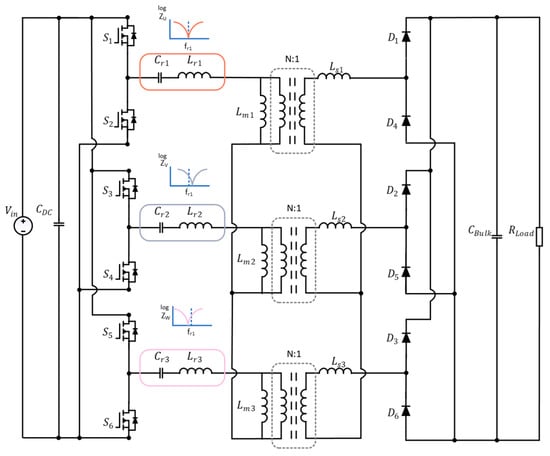
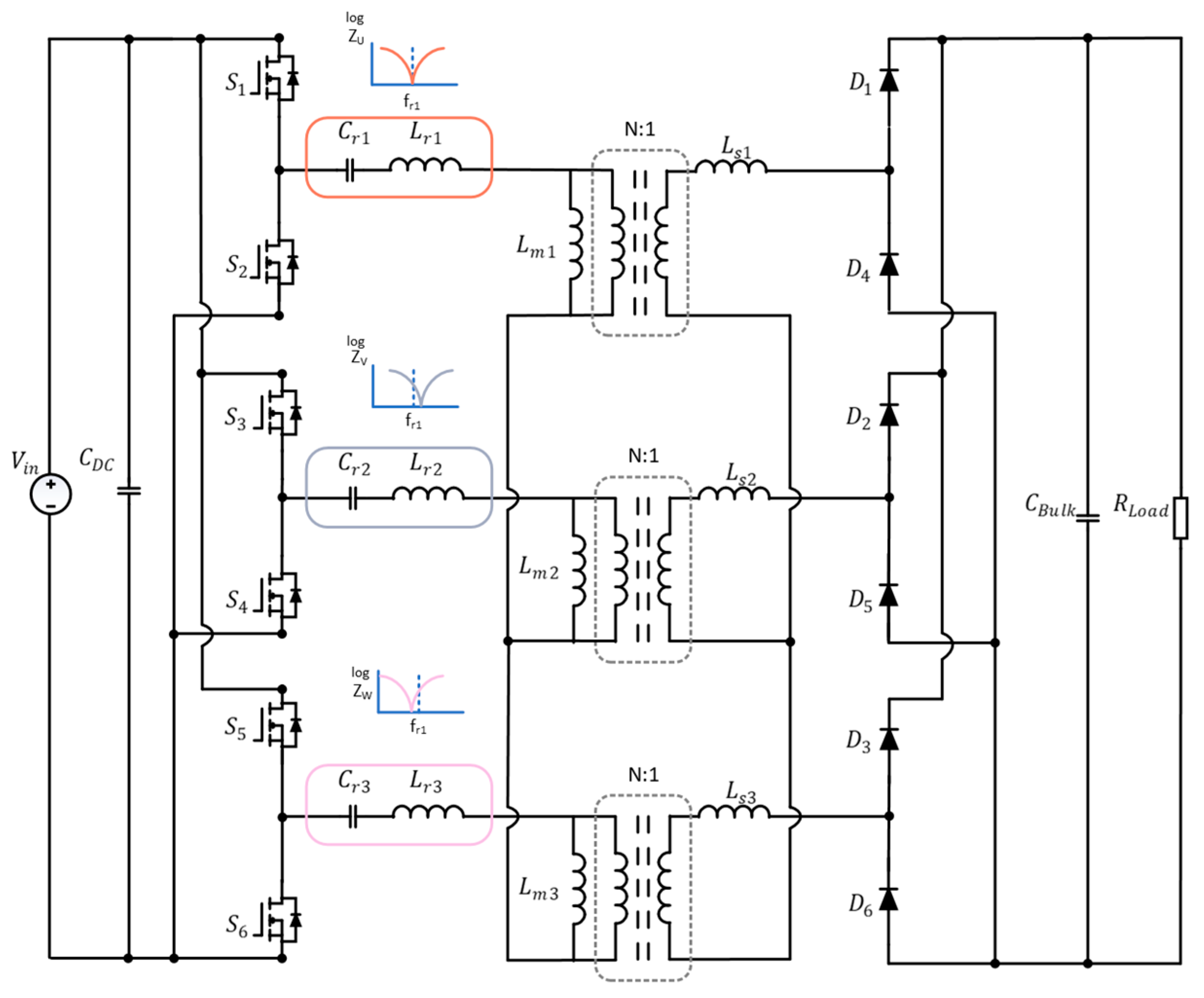
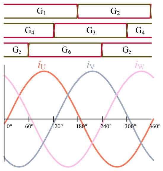
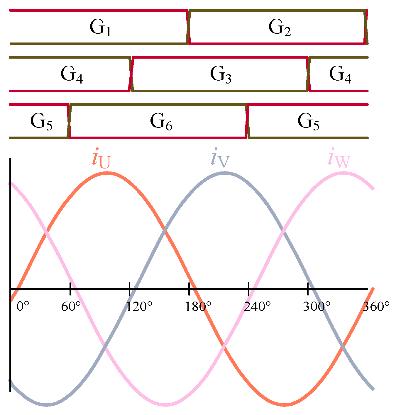
Figure 1 illustrates the structure of the three-phase LLC resonant converter with a Y–Y transformer configuration. Figure 2 presents the switching pattern, including gate drive signals and resonant tank current waveforms.
Figure 1.
Three-phase LLC resonant converter.
Figure 2.
Gate-driver signals of phases U, V, W and resonant tank currents U, V, W in resonant mode.
The converter is characterized by three main passive components: the resonant inductor , the resonant capacitor , and the magnetizing inductance of the transformer . These elements define the operational range of the converter through two resonant frequencies. The first resonant frequency is determined by and as
The second resonant frequency is determined by and the combined inductance
These two frequencies define the converter’s operating range and gain characteristics.
The three-phase LLC resonant converter operates in three distinct frequency regimes, each defined by the relationship between the switching frequency and the first resonant frequency of the resonant tank.
Resonant Mode
In this regime, the converter operates at its first resonant frequency, where the resonant inductor and capacitor form a purely sinusoidal current waveform. This mode enables optimal Zero-Voltage Switching (ZVS) and minimal conduction losses.
Below Resonance
The converter enters the inductive region when the switching frequency is lower than the first resonant frequency. The current waveforms become distorted, and ZVS may be compromised depending on load conditions. This regime typically results in higher gain but reduced efficiency.
Above Resonance
Operation in this regime reduces the gain of the resonant circuit and, as a result, reduces the output voltage. In this mode, the switching losses also increase. While ZVS is maintained, the gain decreases, and the current waveforms deviate from ideal sinusoidal shapes, especially under light load conditions.
The gain of the converter is strongly dependent on the switching frequency, and understanding this relationship is essential for designing control strategies and optimizing performance. This paper provides a brief description of the gain characteristics relevant to the balancing algorithm. For a more detailed analysis of gain behavior and resonant dynamics, the reader is referred to [21].
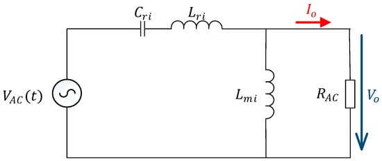
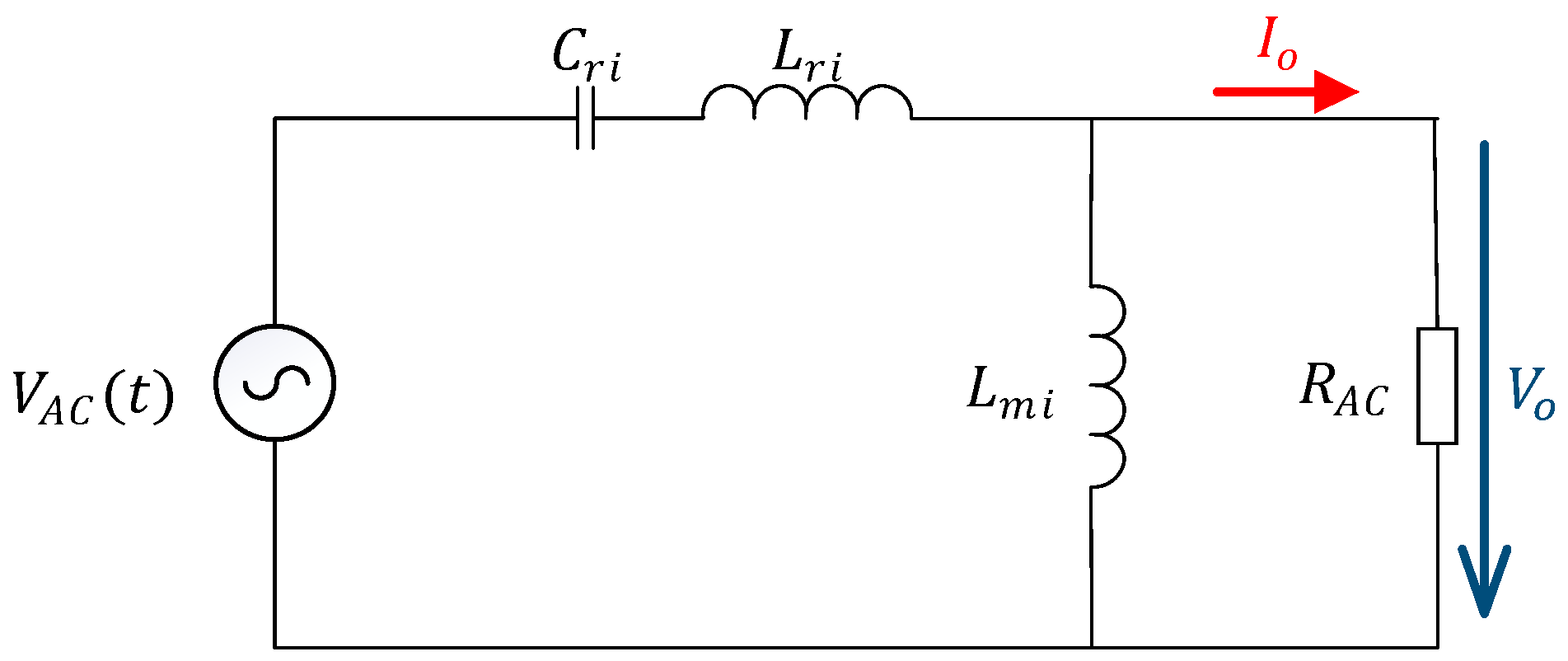
The discussion begins with the equivalent schematic of the three-phase LLC converter, as shown in Figure 3, which serves as the basis for analyzing the resonant behavior and gain characteristics across different operating regimes.
Figure 3.
Per phase equivalent circuit model of three-phase LLC converter, where and are the RMS values.
The first harmonic approximation is used to simplify the analysis of the three-phase LLC resonant converter. This method assumes that the resonant tank primarily responds to the fundamental component of the switching waveform, allowing the converter to be modeled using sinusoidal steady-state techniques, such as phasors (denoted by bold letters in the following text).
Equation (3) describes the transformation from the DC-link voltage to an equivalent AC voltage representation, , which serves as the input to the resonant tank under first harmonic approximation:
where is the DC-link voltage.
This transformation enables the use of phasor analysis and facilitates the derivation of gain characteristics and current behavior across different operating regimes.
The parameter represents the effective resistive load of the converter [24]. A brief analysis of this parameter is presented below. The analysis begins with the equilibrium (lossless system) between input and output power :
The input power is defined as the sum of the RMS currents in each phase multiplied by effective resistive load . Since the phase currents are sinusoidal, a direct relationship can be established between their RMS and peak values.
The output power corresponds to the power delivered on the secondary side after rectification. It can be expressed as the product of the average output current and the load seen by the converter:
Based on the definitions of input and output power, the effective resistive load can be expressed as
where denotes the turns ratio of the transformer.
The relevant parameters for the gain function are expressed as follows:
where is the quality factor, is the inductance ratio, and are the normalized and switching frequencies.
The LLC resonant circuit transfer function is defined by
where represents the amplitude of the input voltage and the average value of the output voltage.
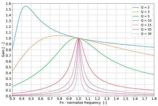
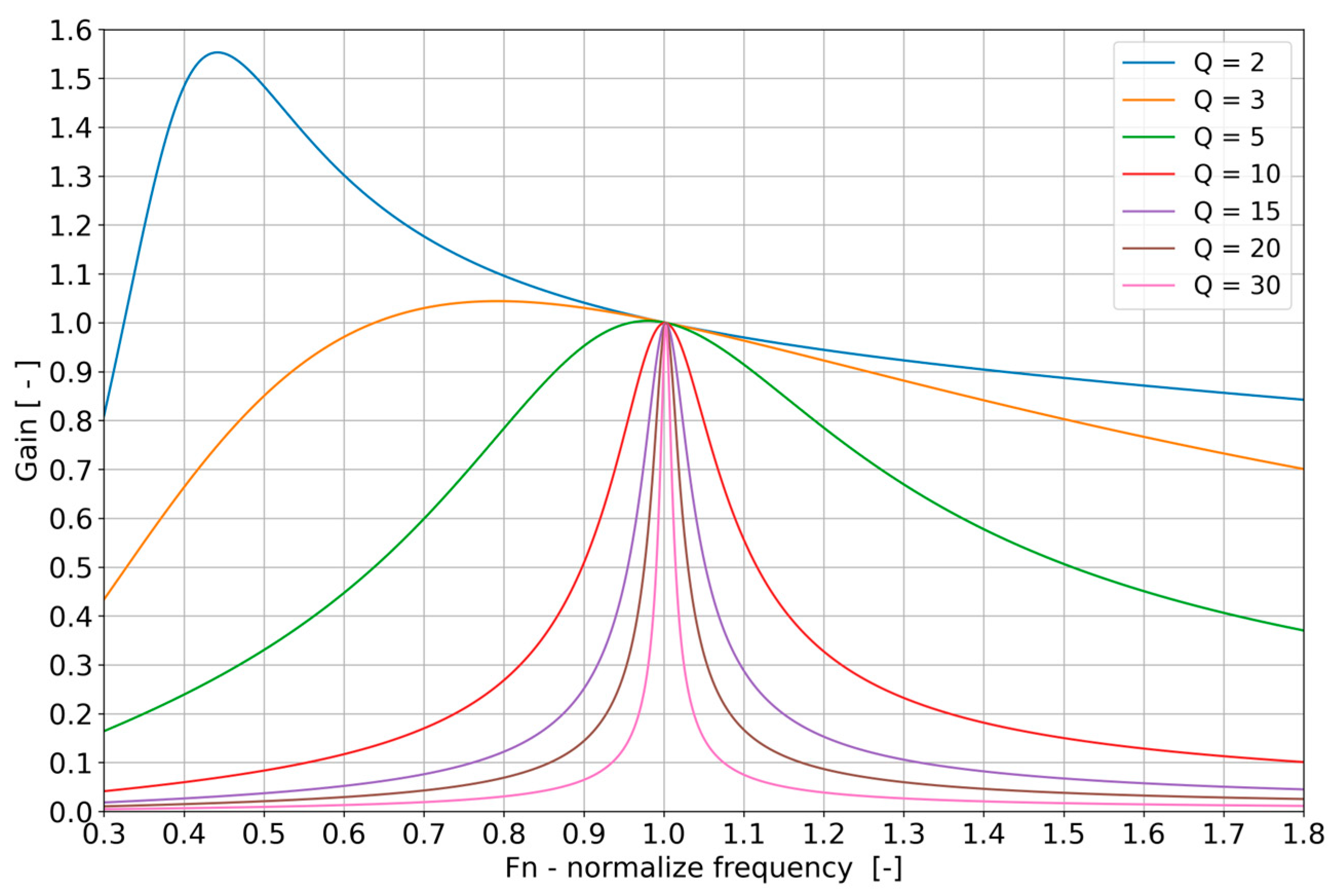
Figure 4 illustrates the gain characteristics of the resonant circuit for various quality factors . The graph is based on ideal component values without tolerance. The selected corresponds to the studied converter.
Figure 4.
Gain characteristics of the LLC resonant circuit with different quality factors; .
The gain profile varies significantly with the quality factor, influencing the converter’s voltage transfer ratio and operating range.
2.1. Current Imbalance and Criterion
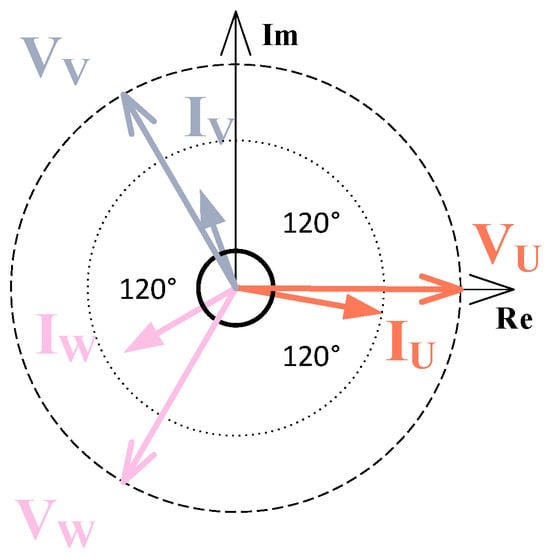
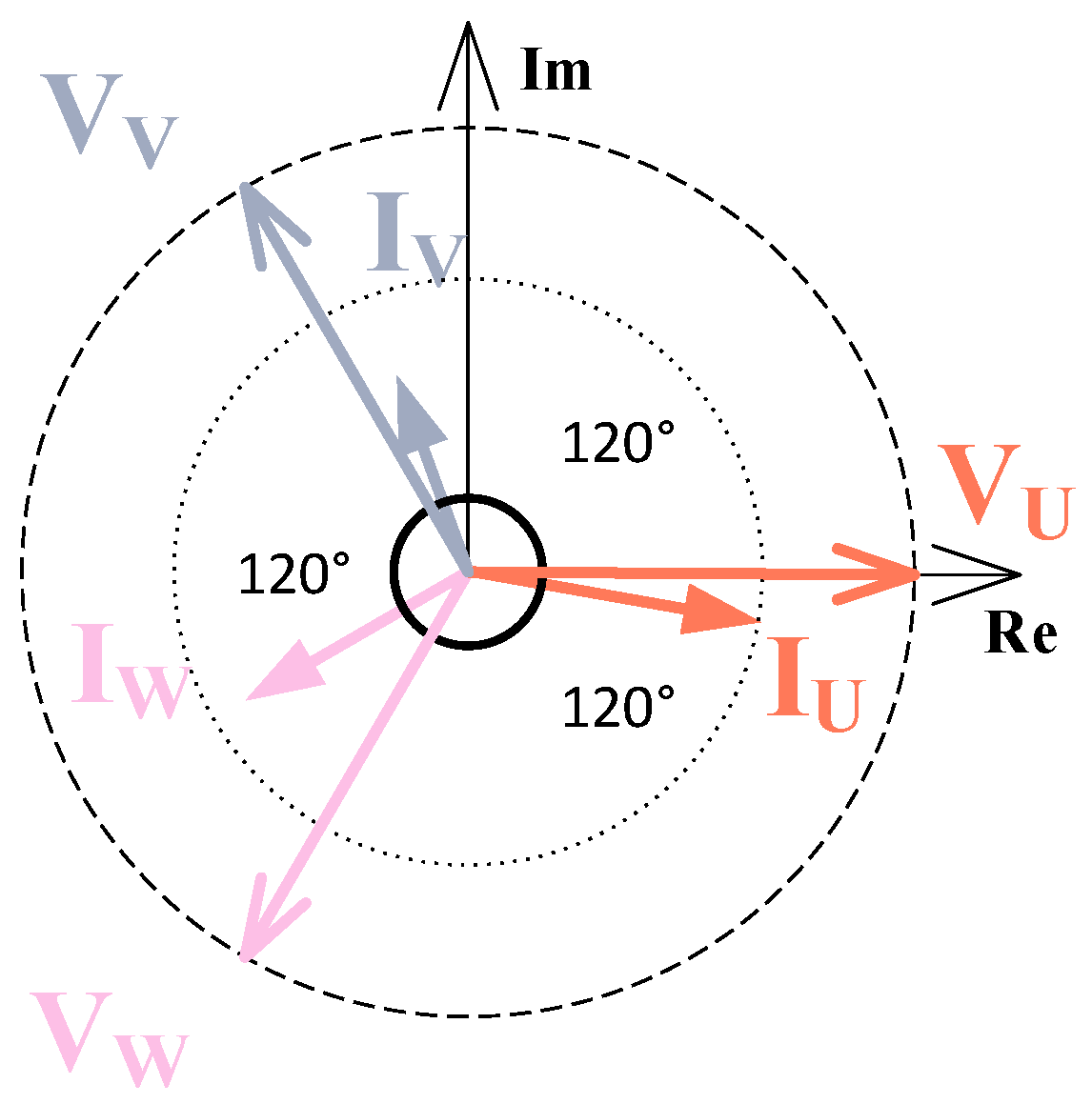
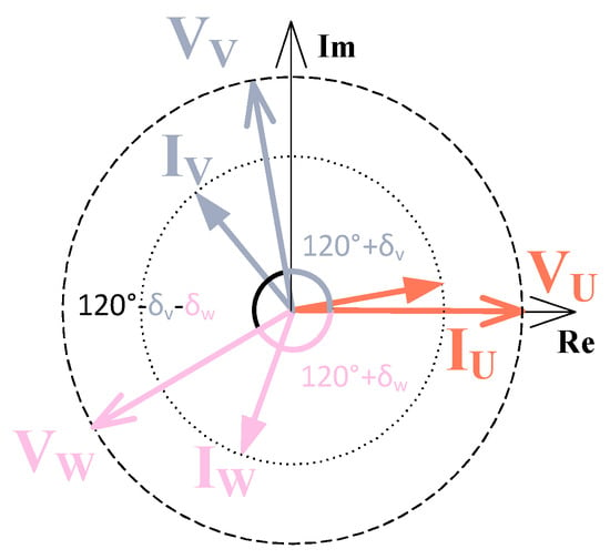
In a real-world circuit, component tolerances—particularly in resonant inductors and capacitors—result in unequal impedance across the converter’s phases, as shown in Figure 5.
Figure 5.
Vector diagram of an unbalanced three-phase LLC converter.
Consequently, the phase currents of the three-phase LLC converter can become asymmetric. To quantify this imbalance, the unbalance factor defined in [29] is adopted:
where , , and are the three-phase RMS input currents.
The RMS values of the phase currents are used because they directly determine conduction losses, which dominate in high-power applications. Thus, RMS-based evaluation provides an accurate criterion for optimizing performance of the three-phase LLC converters.
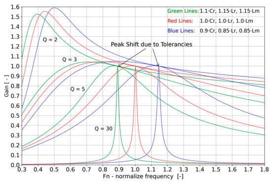
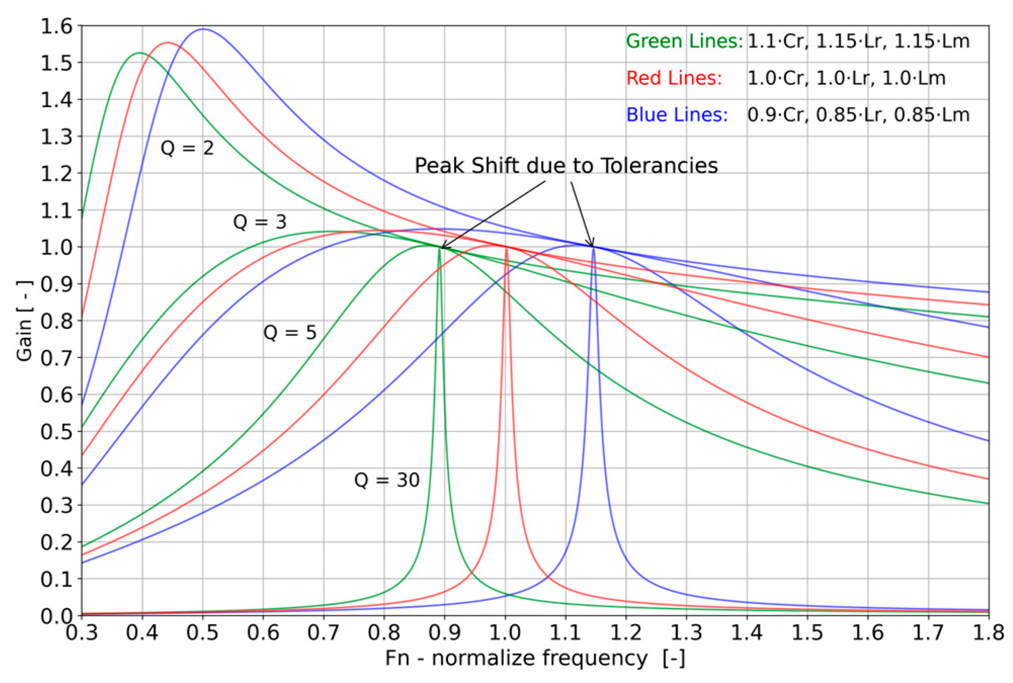
Figure 6 illustrates the worst-case gain characteristics of the LLC resonant converter under three distinct parameter variation scenarios. The green curves represent the case with increased component values: , , . The red curves correspond to the nominal operating conditions, serving as the baseline. The blue curves depict the scenario with reduced component values: , , .
Figure 6.
Gain characteristics of the LLC resonant circuit with different quality factors; .
In some instances, it is possible to observe that a single switching frequency can result in different voltage gains across the three phases of the converter. All three phases work into the same output; thus, the gain is equal, which results in different Q for each phase.
The functional criterion of the algorithm is that all three phases operate under ZVS. The requirement imposes practical limitations on the parameters and . The converter under study operates with in the range of 1.28 to 2.28 and from 0.75 to 1.5, where 100 kHz corresponds to the nominal value . The limitation arising from the transformer design can be mitigated by applying a positive-only tolerance to the leakage inductance.
2.2. Current Balancing
The transformer in Figure 1 is in a star connection, which, according to the Kirchhoff’s current law, means the angle between the balanced phase currents will be 120°. Equation (13) defines the impedance of the equivalent resonant circuit under the first harmonic approximation:
Let us assume that the three-phase voltage phasors are equal in magnitude but with a controllable phase shift and with respect to the reference phase U:
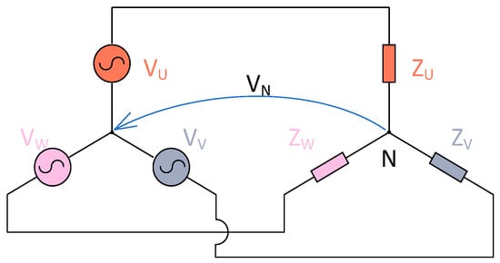
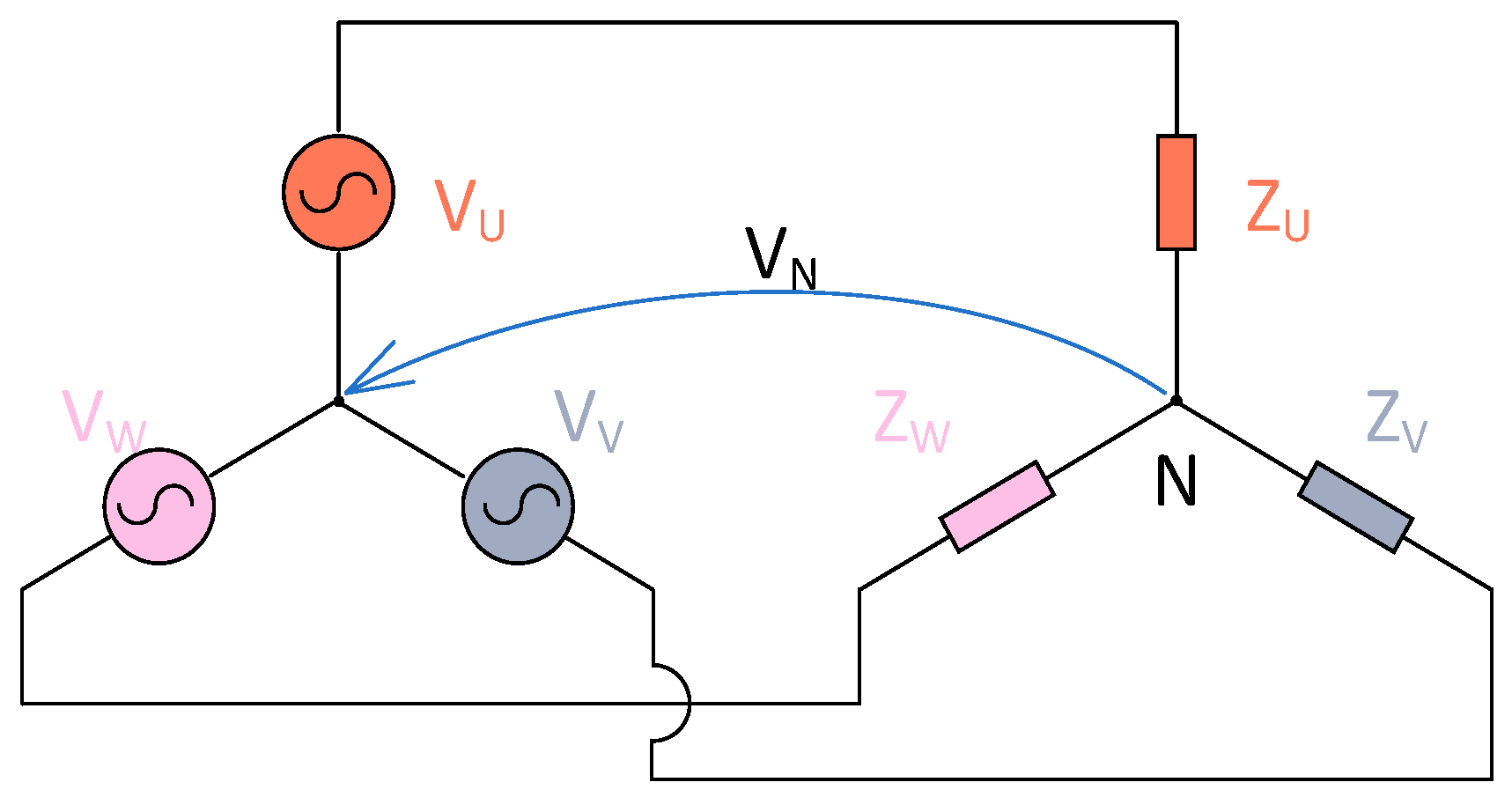
Because the load neutral is floating, its voltage with respect to the source reference is not fixed according to Figure 7.
Figure 7.
Equivalent schematic diagram of three-phase converter.
Using the admittances , the current phasors can be written as
using the substitution as relative admittance. The phase currents can be written as
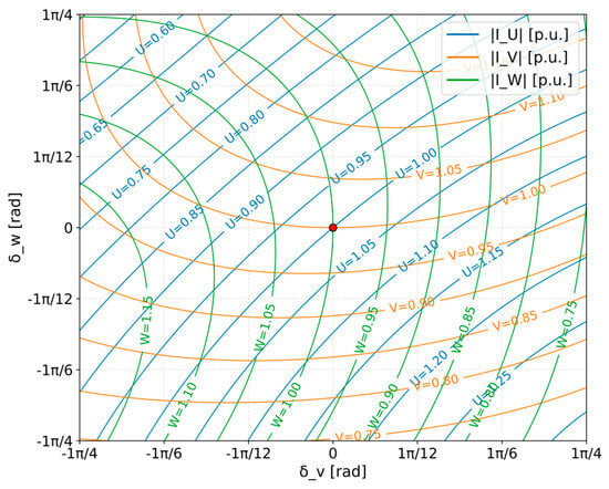
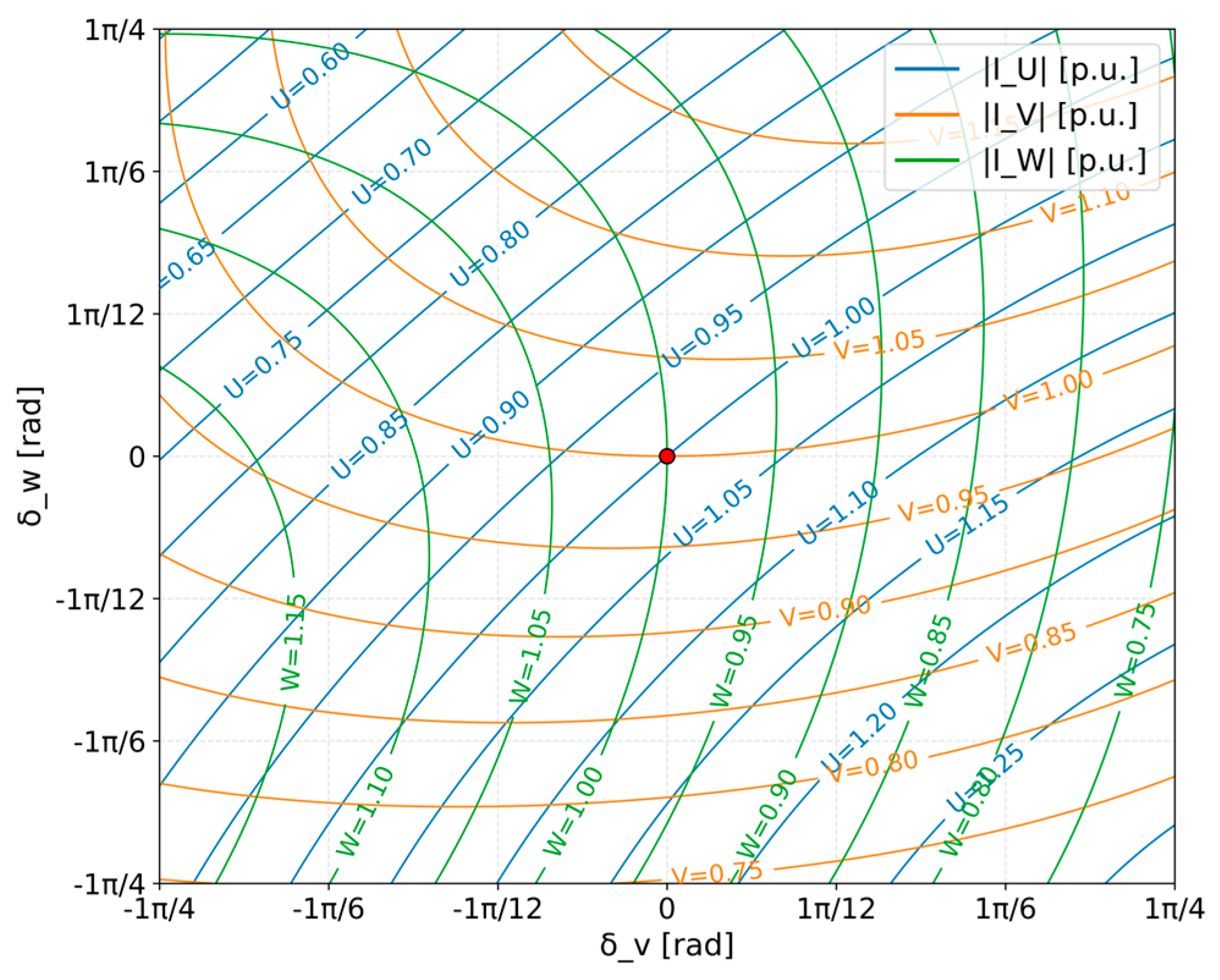
By applying sensitivity analysis to Equations (23)–(25), the influence of each phase shift on the corresponding phase currents can be clearly observed. The results of this analysis are illustrated in Figure 8. All currents are expressed in relative units and are referenced to the balanced state.
Figure 8.
Sensitivity analysis of phase shifts and with symmetrical phases. Phase currents U, V, W are depicted in per unit format.
The red dot corresponds to the point where both phase shifts are unadjusted, i.e., resulting in symmetrical phase voltages. However, the diagram reveals four distinct directional trends:
- Case 1: Increasing leads to a decrease in and increase in
- Case 2: Decreasing leads to an increase in and decrease in
- Case 3: Increasing leads to an increase in and decrease in
- Case 4: Decreasing leads to a decrease in and increase in
All four cases represent valid outputs for the current-balancing algorithm. As illustrated in Figure 9, the algorithm adjusts the phase shifts to achieve balanced phase currents.
Figure 9.
Current-balancing strategy equalizing the phase currents.
2.3. Algorithm Description
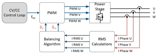
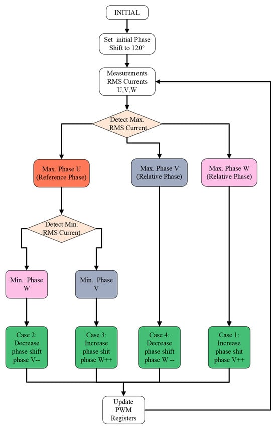
Figure 10 illustrates the implementation of the control logic and the balancing algorithm in the microcontroller. The primary inputs to the balancing algorithm are the phase RMS currents measured on the primary side of the transformer. The balancing algorithm block sets the phase shift of the respected phase voltages.
Figure 10.
Block diagram of balancing algorithm.
A balancing algorithm has been developed to mitigate the current imbalance in the three-phase LLC resonant converters. The algorithm begins with an initial setup, where the phase shift between each phase is set to 120°. Phase U is designated as the reference, while phases V and W are initially shifted by +120° and −120°, respectively. This configuration forms a symmetrical three-phase voltage system applied to the transformer.
Once the converter is initialized, it begins measuring the RMS current of each phase. The RMS value calculation is defined as
where is the number of samples in the sampling window and is the sample index. To avoid calculating the square root, the square of the RMS value is used in the practical implementation.
After obtaining RMS currents, the algorithm identifies the maximum current among the three phases. The phase carrying the maximum current is then targeted for suitable angle adjustment. The adjustment strategy depends on which phase exhibits the maximum RMS current:
- Option 1: Reference phase (U) has the highest RMS current. Since the reference phase has a fixed phase angle (0°), it cannot be adjusted directly. Instead, the algorithm identifies the phase with the lowest RMS current and adjusts the phase-shift register—Case 2 or Case 3. This indirectly reduces the current in the reference phase by altering the relative phase relationships.
- Option 2: Non-reference phase (V or W) has the highest RMS current. The algorithm adjusts the phase shift of the overloaded phase, thereby reducing its current contribution—Case 1 or Case 4.
After each adjustment, the PWM registers are updated. The update frequency is synchronized with the RMS current measurement cycle.
This iterative mechanism ensures that the RMS currents are evenly distributed across all phases. Due to the inherent coupling in three-phase systems with a floating neutral, reducing the current in one phase naturally affects the currents in the other phases. The balancing algorithm accounts for this interdependence and converges toward a balanced steady-state operation. Figure 11 shows the flowchart of the current-balancing algorithm. This algorithm runs continuously, thereby reducing the response time when variation in load occurs.
Figure 11.
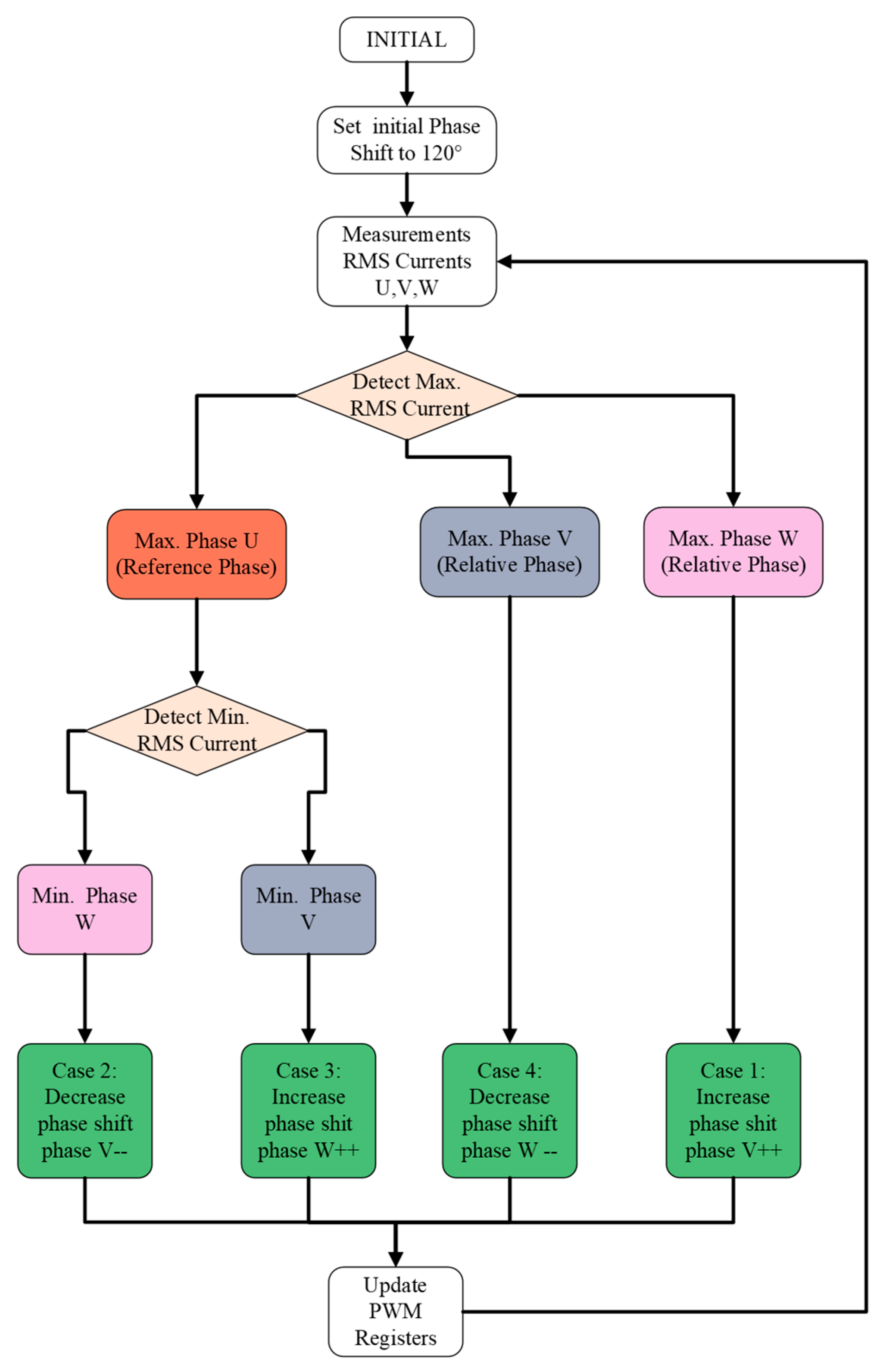
Flowchart of the proposed online current-balancing algorithm.
The resolution of the adjustment is highly dependent on the switching frequency of the converter. The following equation summarizes the resolution of the phase-shift adjustment as a function of the switching frequency:
where is the switching frequency of the converter, is the processor’s main clock. For illustration, the phase-shift resolution corresponds to approximately 0.3° per increment at 75 kHz, 0.4° per increment at 100 kHz, and 0.6° per increment at 150 kHz.
2.4. Simulation Results
The proposed balancing algorithm was first implemented and verified in the PLECS simulation environment. The converter model was developed with integrated balancing control and PWM modulation blocks. The balancing algorithm and PWM modulation were implemented using C-Script, ensuring similarity with the PWM peripheral structure typically found in microcontroller (MCU) firmware.
The simulation was configured with a discrete solver and a fixed time step corresponding to the target MCU clock frequency (90 MHz). To emulate component tolerances, the inductance of phase V increased by 15%.
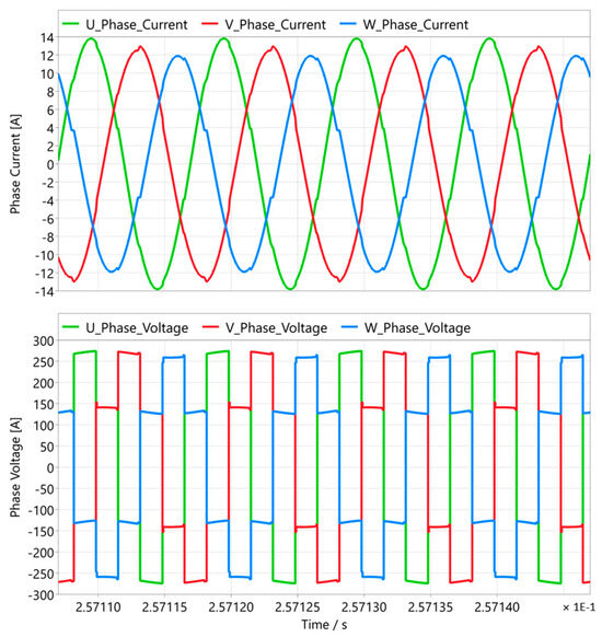
Figure 12 illustrates the operation of the converter without the balancing algorithm. In contrast, Figure 13 presents the behavior of the converter over the same time interval when the balancing algorithm is enabled. The converter was simulated at an operating point of 400 V input voltage, 430 V output voltage, and an output current of 10 A. The simulation results are highlighted in Table 1.
Figure 12.
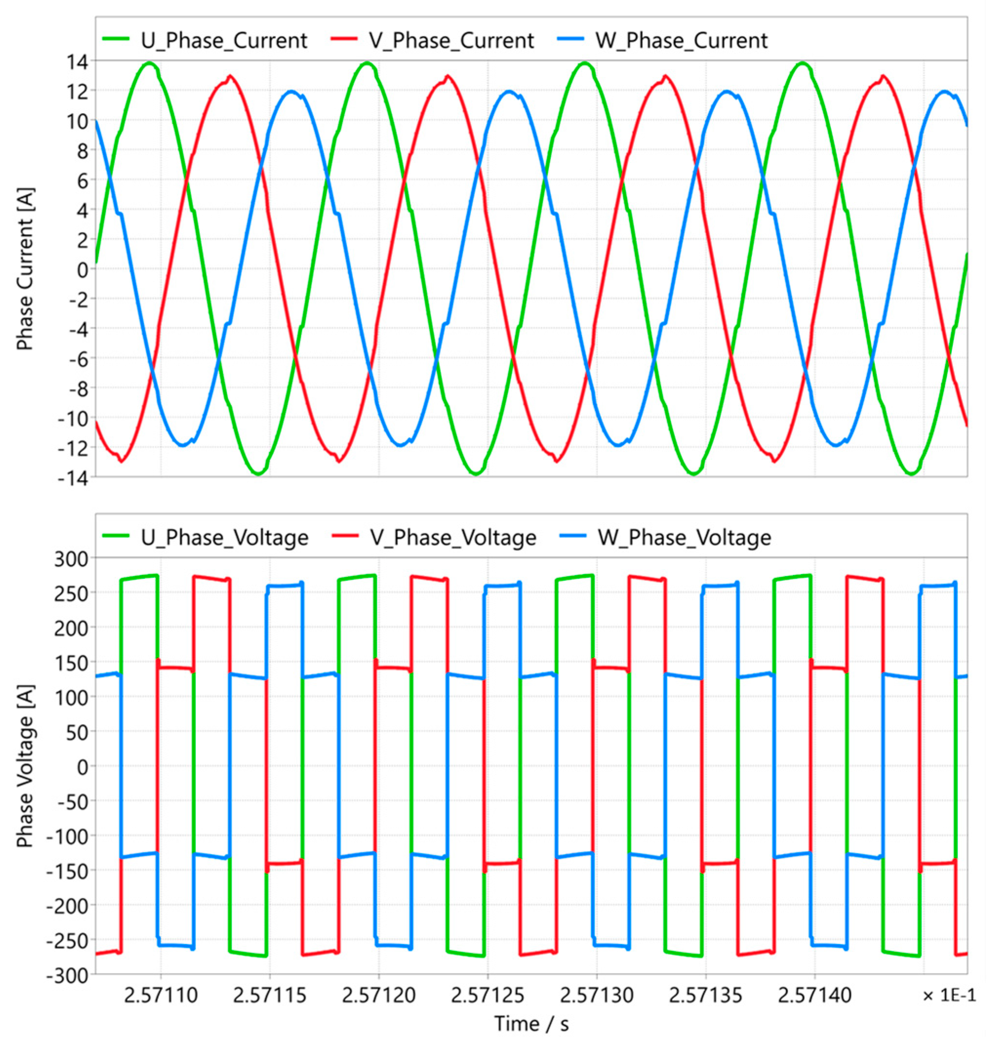
Simulation results. Top: Phase currents; Bottom: Phase voltages, unbalanced currents.
Figure 13.
Simulation results. Top: Phase currents; Bottom: Phase voltages, balanced currents.
Table 1.
Simulation results without and with the balancing algorithm.
It can be observed that the balancing algorithm effectively reduces the current unbalance within the converter. The unbalanced parameter is significantly decreased and falls below 1%.
2.5. Experimental Results
The proposed current-balancing algorithm was implemented and tested on a three-phase LLC resonant converter prototype rated at 11 kW. The main parameters of the converter are summarized in Table 1. The primary side employs a six-pack SiC power module (FS45MR12W1M1). The secondary-side rectifier is implemented on an insulated metal substrate (IMS) board using C6D20065G SiC Schottky diodes (Wolfspeed, Durham, NC, USA), providing high thermal conductivity and efficient heat dissipation. The transformer is a commercially available unitBCBM-11KW-004 from Premo (Málaga, Spain), configured as three single-phase LLC transformers, one for each phase. One of the key components of the converter is the current-sensing stage. Each phase is equipped with a TMCS1133A4A Hall-effect current sensor (Texas Instruments, Dallas, TX, USA), providing a bandwidth of 1 MHz. A TMS320F82069 DSP executes real-time control and ADC measurements. The laboratory test bench is shown in Figure 14. A control PC communicated with the microcontroller to configure operating points, monitor variables, and log data. Waveforms were captured using a digital oscilloscope, while thermal performance was evaluated with an infrared camera. Two bi-directional power supplies were used: one served as the DC input source, and the other operated as an electronic load in constant resistance mode. The parameters of the converter are summarized in Table 2.
Figure 14.
Laboratory test setup.
Table 2.
Overview of converter parameters.
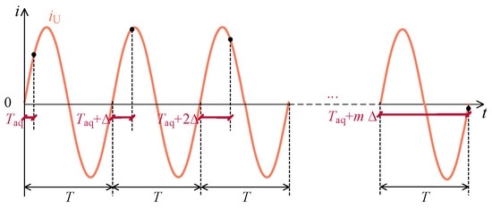
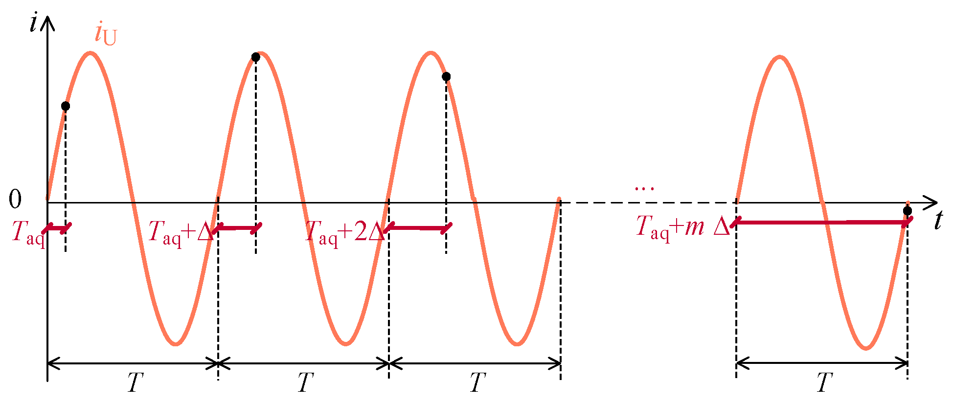
The measurement of RMS phase currents is implemented using the microcontroller’s internal Analog-to-Digital Converter (ADC). Since the device features only a single ADC core, it is inherently limited to sampling one signal at a time. A time-interleaved sampling strategy was employed to address this constraint. The ADC is triggered by a timer that is synchronized with the PWM switching cycle. Upon each trigger event, the ADC sequentially samples the phase currents in the following order: U, V, and W. This results in one sample per phase per period. After completing this sequence (U, V, W), the ADC trigger is moved forward by Δ, as shown in Figure 15. The interval Δ corresponds to five clock cycles of the PWM timer. Since Δ is defined, the number of samples for the up–down counter can be calculated as
where is the processor’s main clock, is the switching frequency of the converter, and is the increment of the PWM timer (five clock cycles). The coefficient of two corresponds to the up–down counter. Given the system clock of 90 MHz and a switching frequency of 100 kHz, each PWM period spans 450 clock cycles. With a five-clock increment per sampling step, the system achieves 90 distinct sampling points per switching period. Consequently, the RMS current is computed over 90 converter cycles, providing a sufficient resolution to represent the current waveform for control purposes. This sampling method ensures that each phase is sampled uniformly across the switching period, despite the limitation of the single-core ADC. After the square of RMS values is computed, the measurement cycle restarts, enabling continuous monitoring and real-time feedback for the balancing algorithm, as shown previously in Figure 11. The sampling sequence with trigger increment for a single phase is depicted in Figure 15.
Figure 15.
RMS current sampling time diagram. denotes the acquisition time of ADC, represents the trigger step, and is the numbers of samples.
The sensitivity and error of the current sensor is ±0.1%, with a resolution of 100 mV/A according to the datasheet. The system uses a 12-bit ADC with a 3.3 V reference, resulting in an ADC resolution of approximately 0.81 mV per bit. This corresponds to a current measurement resolution of roughly 10 mA per bit, which is sufficient for the proposed 11 kW power level.
2.6. Dynamic Behavior of Balancing Algorithm
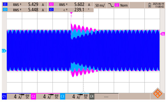
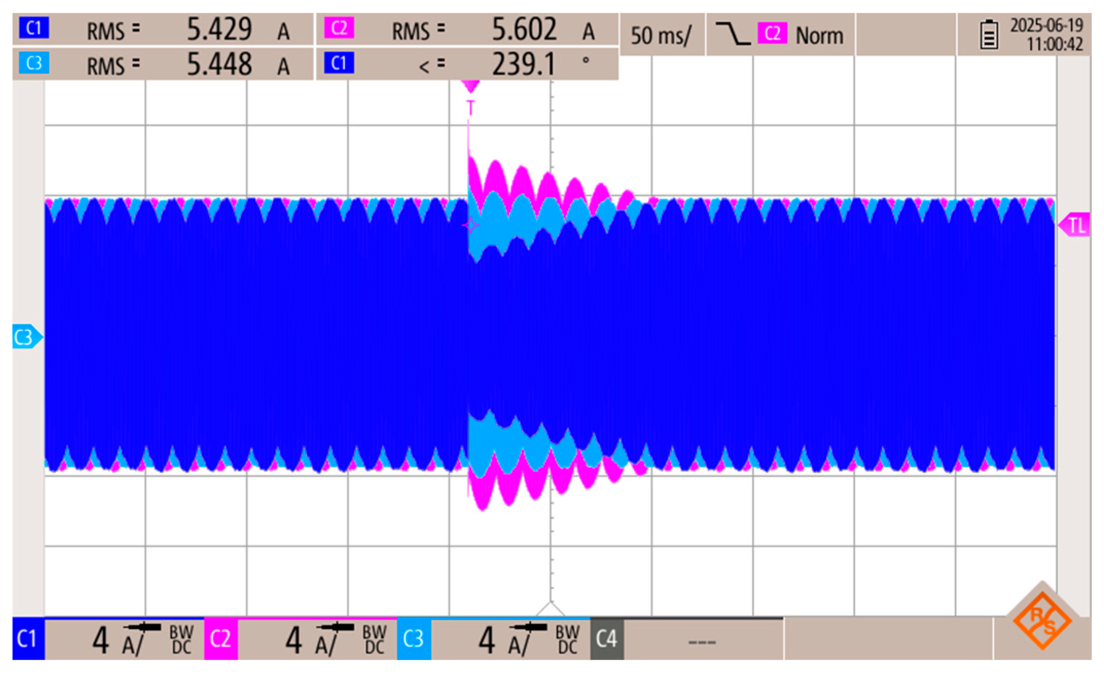
The dynamic response of the balancing algorithm was first investigated by deliberately disturbing the phase balance. Figure 16 shows the measured RMS currents of phases U (blue), V (magenta), and W (turquoise). Initially, the converter operated in a balanced state under the algorithm’s action.
Figure 16.
Dynamic test of the balancing algorithm. C1 (blue)—phase U current, C2 (magenta)—phase V current, C3 (turquoise)—phase W current.
To test responsiveness, the phase shift of phase V was manually forced to 150°, which decreased its current and also influenced other phases due to the inherent coupling (Y connection). The algorithm detected this imbalance and adjusted the phase shifts accordingly. Within approximately 100 ms, the currents converged back to a balanced state.
This experiment demonstrates that the algorithm effectively restores current symmetry under transient conditions. The response time is primarily limited by the MCU acquisition interval and the RMS calculation window but remains suitable even for high-frequency converter operation.
3. Results
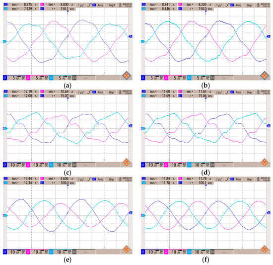
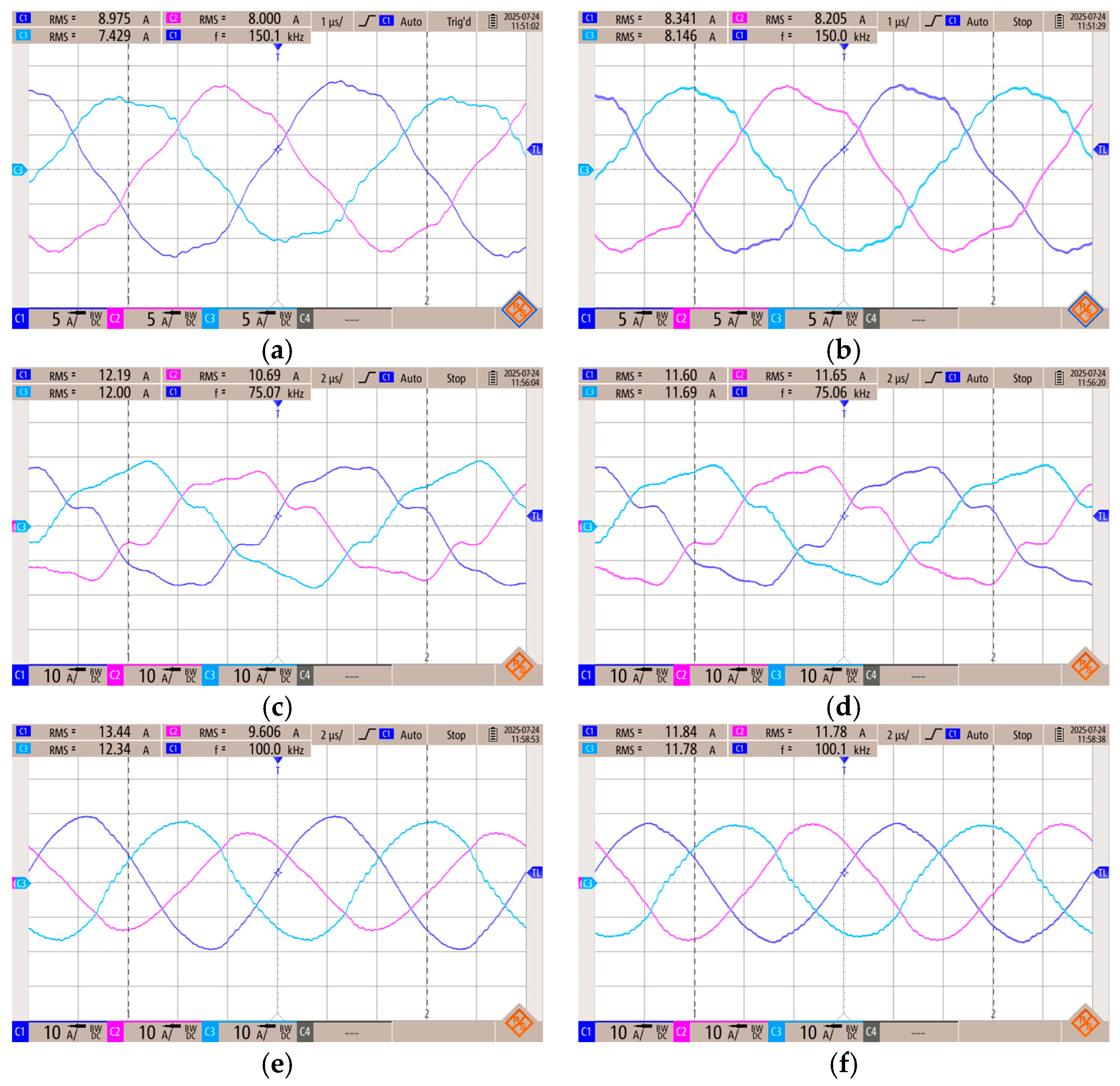
To evaluate steady-state performance, the algorithm was tested at three representative operating points: above resonance (150 kHz), at resonance (100 kHz), and below resonance (75 kHz). Figure 17 compares the measured phase currents with and without the balancing algorithm for each frequency, and Table 3 summarizes the results. The input voltage was set to 400 V while the output voltage and power were: 325 V and 3.25 kW at 150 kHz, 509 V and 6.169 kW at 75 kHz, and 434 V and 6.27 kW at 100 kHz, respectively. The unbalanced operation was achieved by artificially increasing the inductance of phase W by 10%.
Figure 17.
Experimental waveforms at different switching frequencies with component mismatch ( of phase W increased by 10%): (a) 150 kHz without OBA, (b) 150 kHz with OBA, (c) 75 kHz without OBA, (d) 75 kHz with OBA, (e) 100 kHz without OBA, (f) 100 kHz with OBA.
Table 3.
Measurements results.
Significant asymmetry occurred without the balancing algorithm, with the unbalance factor exceeding 20% at resonance. Once the algorithm was enabled, the current deviation was reduced to below 2% across the entire frequency range.
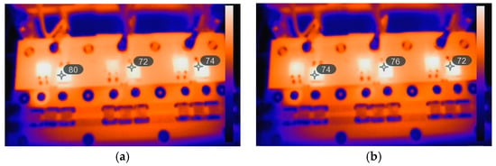
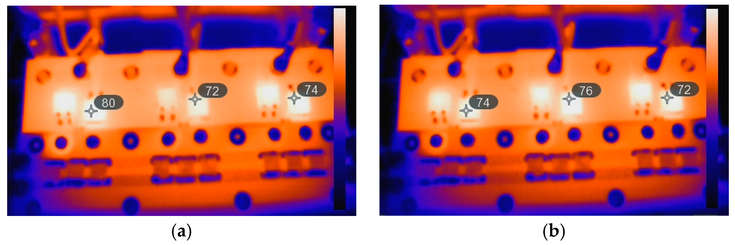
The influence of the current balancing on thermal distribution within the converter was evaluated through infrared thermography of the secondary-side rectifier. The results, captured at a switching frequency of 100 kHz, are presented in Figure 18. This operating point corresponds to the worst-case imbalance scenario identified in Table 4.
Figure 18.
Thermal images of rectifier diodes at 100 kHz: (a) without algorithm, (b) with algorithm.
Table 4.
Thermal measurements results.
Without the balancing algorithm, the thermal image revealed a non-uniform temperature distribution across the rectifier diodes. Specifically, the central diode associated with phase V exhibited significantly lower temperatures, indicating reduced current conduction. In contrast, the remaining diodes experienced elevated thermal stress due to disproportionate current sharing.
Upon activation of the balancing algorithm, the temperature profile became more uniform (the middle diode being the hottest as expected since its neighbors also influence it). This outcome confirms that the algorithm effectively redistributed the current among the phases, thereby enhancing current symmetry and reducing localized thermal loading.
After activating the balancing algorithm, the thermal distribution across the rectifier diodes became more uniform. This improvement is clearly illustrated in Table 4, which summarizes the thermal performance before and after the balancing; the corresponding operational points are provided in brackets.
4. Discussion
Table 5 provides a qualitative comparison of the proposed balancing methods from the literature. Most phase-balancing algorithms existing in the literature rely on extra hardware such as CLC filters [25], balancing transformers [26], or analog sensing circuits [27,28]. In contrast, our algorithm uses only the phase current sensors that are already standard in multiphase converters, making the method easy to apply without hardware changes.
Table 5.
Comparison with existing methods.
Software-based methods, such as the algorithm in [29], apply a nonlinear function for tunning the phase-shift correction. These nonlinear functions can be complicated to tune and can provide unpredictable results in following iterations. Our method uses a linear, equal-step adjustment strategy which improves numerical stability and ensures consistent behavior across the operating range.
Because the proposed method does not depend on analog filters, it can operate across the full switching-frequency range and can theoretically be extended further. Direct measurement of phase currents also improves the accuracy of current balancing.
Overall, the proposed approach offers an extra hardware-free, digitally robust, and stable alternative to existing solutions.
While effective, the proposed algorithm has a few practical limitations:
- The ADC acquisition time is a limiting factor in the algorithm’s response speed. Employing microcontrollers with a higher number of ADC cores can improve the acquisition rate.
- Phase-shift resolution is limited by the PWM clock frequency. However, advanced timers with higher resolution can significantly enhance the precision of adjustment.
- Operating frequency dependence: At high switching frequencies, the absolute time corresponding to a phase shift decreases, which may restrict the algorithm’s adjustment range.
However, these limitations can be addressed by DSP with high-resolution timers or faster clock frequencies.
5. Conclusions
An online current-balancing algorithm for three-phase LLC resonant converters has been developed and validated in simulations and experiments. The method dynamically adjusts input voltage phase shifts based on RMS current measurements, eliminating the need for additional hardware or computationally intensive, potentially unstable trigonometric operations.
Experimental results on an 11 kW prototype demonstrated that the algorithm reduces the current unbalance coefficient from values exceeding 20% to below 2% across the full operating frequency range. This improvement directly enhances the distribution of conduction loss and thermal uniformity as confirmed by thermal imaging, leading to increased converter reliability. The presented approach mitigates the impact of component tolerances, reducing the need for highly precise passive elements and enabling cost-effective designs.
The proposed algorithm, therefore, provides a robust and practical solution for high-power applications requiring compact size, high efficiency, and thermal stability.
Future work will focus on the replacement of phase current sensors to single-output current sensors.
Author Contributions
Conceptualization, F.F.; Methodology, F.F.; Software, F.F. and P.S.; Validation, F.F. and P.S.; Formal analysis, F.F. and P.S.; Investigation, F.F.; Writing—original draft, F.F.; Writing—review & editing, F.F. and P.S.; Supervision, J.L. All authors have read and agreed to the published version of the manuscript.
Funding
This research was funded by Student Grant Competition of CTU grant No. SGS25/140/OHK3/3T/13.
Data Availability Statement
The original contributions presented in this study are included in the article. Further inquiries can be directed to the corresponding author.
Conflicts of Interest
The authors declare no conflict of interest.
References
- Lee, F.C.; Wang, S.; Li, Q. Next Generation of Power Supplies—Design for Manufacturability. IEEE J. Emerg. Sel. Top. Power Electron. 2021, 9, 6462–6475. [Google Scholar] [CrossRef] [Scilit]
- Ouyang, Z.; Andersen, M.A.E. High Frequency LLC Resonant Converter with Magnetic Shunt Integrated Planar Transformer. In 2018 IEEE Applied Power Electronics Conference and Exposition (APEC); IEEE: Piscataway, NJ, USA, 2018; Volume 9, pp. 2678–2685. [Google Scholar] [CrossRef] [Scilit]
- Hou, Z.; Jiao, D.; Lai, J.-S. A Novel 500-Khz LLC-T Resonant Converter with Wide Output Range. In 2025 IEEE Applied Power Electronics Conference and Exposition (APEC); IEEE: Piscataway, NJ, USA, 2025; Volume 9, pp. 1913–1918. [Google Scholar] [CrossRef] [Scilit]
- Shen, J.; Jing, L.; Qiu, J. High-Frequency Full-Bridge 48V Dc-5V Dc LLC Resonant Converter with Algan/Gan Hemts. In 2023 5th International Conference on Electrical Engineering and Control Technologies (CEECT); IEEE: Piscataway, NJ, USA, 2023; Volume 9, pp. 338–342. [Google Scholar] [CrossRef] [Scilit]
- Guan, Y.; Wen, Z.; Wang, Y.; Xu, D. A Single-Stage Modular Dcx with High Voltage Conversion Ratio Based on High Frequency LLC Resonant Converter. In 2021 IEEE Workshop on Wide Bandgap Power Devices and Applications in Asia (WiPDA Asia); IEEE: Piscataway, NJ, USA, 2021; Volume 9, pp. 132–137. [Google Scholar] [CrossRef] [Scilit]
- Pajnic, M.; Pejovic, P.; Despotovic, Z.; Lazic, M.; Skender, M. Design Consideration for High Frequency LLC Resonant Converter with Matrix Transformer. In 2017 International Symposium on Power Electronics (Ee); IEEE: Piscataway, NJ, USA, 2017; Volume 9, pp. 1–6. [Google Scholar] [CrossRef] [Scilit]
- Wang, H.; Chen, Y.; Liu, Y.-F.; Afsharian, J.; Yang, Z.A. A Common Inductor Multi-Phase LLC Resonant Converter. In 2015 IEEE Energy Conversion Congress and Exposition (ECCE); IEEE: Piscataway, NJ, USA, 2015; Volume 9, pp. 548–555. [Google Scholar] [CrossRef] [Scilit]
- Ahmad, U.; Giral, R.; Olalla, C.; Sangwongwanich, A.; Davari, P.; Blaabjerg, F. Multiphase LLC Resonant Converter with Natural Current Sharing and Phase-Shedding. IEEE Trans. Ind. Appl. 2025, 61, 6524–6534. [Google Scholar] [CrossRef] [Scilit]
- Wang, H.; Chen, Y.; Hu, Z.; Wang, L.; Qiu, Y.; Liu, W.; Liu, Y.-F.; Afsharian, J.; Yang, Z. A Common Capacitor Multi-Phase LLC Resonant Converter. In 2016 IEEE Applied Power Electronics Conference and Exposition (APEC); IEEE: Piscataway, NJ, USA, 2016; Volume 61, pp. 2320–2327. [Google Scholar] [CrossRef] [Scilit]
- Igorovych Zaikin, D.; Kolding Andersen, M.; Brix Rugtved Rugholt, M.; Krag Kjeldsen, T.; Davari, P.; Liu, W.; Liu, Y.-F.; Afsharian, J.; Yang, Z. Optimized Design of Multi-Channel Resonant Converter for Fuel Cell Application. IEEE Access 2024, 12, 66605–66624. [Google Scholar] [CrossRef] [Scilit]
- Gadelrab, R.; Lee, F.C.; Li, Q.; Krag Kjeldsen, T.; Davari, P.; Liu, W.; Liu, Y.-F.; Afsharian, J.; Yang, Z. Three-Phase Interleaved LLC Resonant Converter with Integrated Planar Magnetics for Telecom and Server Application. In 2020 IEEE Applied Power Electronics Conference and Exposition (APEC); IEEE: Piscataway, NJ, USA, 2020; Volume 12, pp. 512–519. [Google Scholar] [CrossRef] [Scilit]
- Cao, J.; Zhang, X.; Rao, P.; Zhou, S.; Zhou, F.; Zhang, Q.; Liu, Y.-F.; Afsharian, J.; Yang, Z. Design of Three-Phase Delta-Delta LLC Resonant Converter. In 2020 IEEE Vehicle Power and Propulsion Conference (VPPC); IEEE: Piscataway, NJ, USA, 2020; Volume 12, pp. 1–5. [Google Scholar] [CrossRef] [Scilit]
- Binder, J.; Oeder, C.; Barwig, M.; Duerbaum, T.; Zhou, F.; Zhang, Q.; Liu, Y.-F.; Afsharian, J.; Yang, Z. Influence Of Component Tolerances onto Design and Losses of Resonant LLC Converters. In 2014 16th European Conference on Power Electronics and Applications; IEEE: Piscataway, NJ, USA, 2014; Volume 12, pp. 1–10. [Google Scholar] [CrossRef] [Scilit]
- Austrup, I.; van der Broeck, C.H.; Kalker, S.; Albert, T.B.; Janoth, F.; De Doncker, R.W.; Liu, Y.-F.; Afsharian, J.; Yang, Z. Diagnosing Thermal-Interface Aging of Power Devices Using Self-Sensing. IEEE Trans. Power Electron. 2025, 40, 4386–4398. [Google Scholar] [CrossRef] [Scilit]
- Xu, M.; Ma, K.; Zhong, Q.; Albert, T.B.; Janoth, F.; De Doncker, R.W.; Liu, Y.-F.; Afsharian, J.; Yang, Z. Degradation Diagnosis of Power Module Based on Frequency Characteristics in Heat Flow. IEEE Trans. Power Electron. 2023, 38, 10292–10301. [Google Scholar] [CrossRef] [Scilit]
- Guan, J.; Wu, Z.; Liu, T.; Wen, J.; Xu, W.; Chen, C.; Kang, Y.; Afsharian, J.; Yang, Z. A High Efficiency Δ-Lr-Y Type Three-Phase Interleaved LLC Converter with Less Transformer Loss. IEEE Trans. Power Electron. 2023, 38, 11152–11168. [Google Scholar] [CrossRef] [Scilit]
- Wang, J.; Fu, D.; Pei, W.; Yang, Z.; Xu, W.; Chen, C.; Kang, Y.; Afsharian, J.; Yang, Z. Magnetic Integrated Five-Phase LLC Resonant Converter for Offshore Wind Power System. In 2023 IEEE 6th International Electrical and Energy Conference (CIEEC); IEEE: Piscataway, NJ, USA, 2023; Volume 38, pp. 1814–1819. [Google Scholar] [CrossRef] [Scilit]
- Gadelrab, R.; Lee, F.C.; Pei, W.; Yang, Z.; Xu, W.; Chen, C.; Kang, Y.; Afsharian, J.; Yang, Z. Pcb-Based Magnetic Integration and Design Optimization for Three-Phase LLC. IEEE Trans. Power Electron. 2023, 38, 14037–14049. [Google Scholar] [CrossRef] [Scilit]
- Li, T.; Wen, J.; Guan, J.; Liu, J.; Chen, C.; Kang, Y.; Kang, Y.; Afsharian, J.; Yang, Z. Design Optimization and Planar Magnetics Integration Of Three-Phase Interleaved LLC Resonant Converter. In 2024 IEEE Energy Conversion Congress and Exposition (ECCE); IEEE: Piscataway, NJ, USA, 2024; Volume 38, pp. 3022–3025. [Google Scholar] [CrossRef] [Scilit]
- Shen, C.; Ruan, X.; Zhao, H.; Liu, J.; Chen, C.; Kang, Y.; Kang, Y.; Afsharian, J.; Yang, Z. A Three Phase Interleaved LLC Resonant Converter with Improved Integrated Planar Magnetics. In 2024 IEEE 10th International Power Electronics and Motion Control Conference (IPEMC2024-ECCE Asia); IEEE: Piscataway, NJ, USA, 2024; Volume 38, pp. 3835–3839. [Google Scholar] [CrossRef] [Scilit]
- Noah, M.; Kimura, S.; Endo, S.; Yamamoto, M.; Imaoka, J.; Umetani, K.; Martinez, W.; Afsharian, J.; Yang, Z. A Novel Three-Phase LLC Resonant ConverteIntegrated Magnetics for Lower Turn-Off Losses and Higher Power Density. In 2017 IEEE Applied Power Electronics Conference and Exposition (APEC); IEEE: Piscataway, NJ, USA, 2017; Volume 38, pp. 322–329. [Google Scholar] [CrossRef] [Scilit]
- Xue, B.; Wang, H.; Liang, J.; Cao, Q.; Li, Z. Phase-Shift Modulated Interleaved LLC Converter with Ultrawide Output Voltage Range. IEEE Trans. Power Electron. 2021, 36, 493–503. [Google Scholar] [CrossRef] [Scilit]
- Rehlaender, P.; Schafmeister, F.; Bocker, J. Interleaved Single-Stage LLC Converter Design Utilizing Half- and Full-Bridge Configurations for Wide Voltage Transfer Ratio Applications. IEEE Trans. Power Electron. 2021, 36, 10065–10080. [Google Scholar] [CrossRef] [Scilit]
- Almardy, M.S.; Bhat, A.K.S.; Endo, S.; Yamamoto, M.; Imaoka, J.; Umetani, K.; Martinez, W.; Afsharian, J.; Yang, Z. Three-Phase (Lc)(L)-Type Series-Resonant Converter: Design and Experimental Results. In 2010 International Conference on Electronic Devices, Systems and Applications; IEEE: Piscataway, NJ, USA, 2010; Volume 38, pp. 70–75. [Google Scholar] [CrossRef] [Scilit]
- Wang, J.; Pei, W.; Hu, J.; Zhao, S.; Zhuang, J.; Umetani, K.; Martinez, W.; Afsharian, J.; Yang, Z. Five-Phase LLC Resonant Dc/Dc Converter Utilizing Clc Filter for Current Sharing. IEEE Trans. Ind. Electron. 2023, 70, 8634–8644. [Google Scholar] [CrossRef] [Scilit]
- Noah, M.; Endo, S.; Ishibashi, H.; Nanamori, K.; Imaoka, J.; Umetani, K.; Yamamoto, M.; Afsharian, J.; Yang, Z. A Current Sharing Method Utilizing Single Balancing Transformer for a Multiphase LLC Resonant Converter with Integrated Magnetics. IEEE J. Emerg. Sel. Top. Power Electron. 2018, 6, 977–992. [Google Scholar] [CrossRef] [Scilit]
- Kim, H.-S.; Baek, J.-W.; Ryu, M.-H.; Kim, J.-H.; Jung, J.-H.; Umetani, K.; Yamamoto, M.; Afsharian, J.; Yang, Z. The High-Efficiency Isolated Ac–Dc Converter Using the Three-Phase Interleaved LLC Resonant Converter Employing the Y-Connected Rectifier. IEEE Trans. Power Electron. 2014, 29, 4017–4028. [Google Scholar] [CrossRef] [Scilit]
- Orietti, E.; Mattavelli, P.; Spiazzi, G.; Adragna, C.; Gattavari, G.; Umetani, K.; Yamamoto, M.; Afsharian, J.; Yang, Z. Current Sharing in Three-Phase LLC Interleaved Resonant Converter. In 2009 IEEE Energy Conversion Congress and Exposition; IEEE: Piscataway, NJ, USA, 2009; Volume 29, pp. 1145–1152. [Google Scholar] [CrossRef] [Scilit]
- Arshadi, S.A.; Ordonez, M.; Eberle, W.; Saket, M.A.; Craciun, M.; Botting, C. Unbalanced Three-Phase LLC Resonant Converters: Analysis and Trigonometric Current Balancing. IEEE Trans. Power Electron. 2019, 34, 2025–2038. [Google Scholar] [CrossRef] [Scilit]

Disclaimer/Publisher’s Note: The statements, opinions and data contained in all publications are solely those of the individual author(s) and contributor(s) and not of MDPI and/or the editor(s). MDPI and/or the editor(s) disclaim responsibility for any injury to people or property resulting from any ideas, methods, instructions or products referred to in the content. |
© 2026 by the authors. Licensee MDPI, Basel, Switzerland. This article is an open access article distributed under the terms and conditions of the Creative Commons Attribution (CC BY) license.