


Abstract
Advances in semiconductor technologies, particularly in power transistors and switching diodes, have enabled higher switching frequencies and converter efficiency, renewing interest in Switched Reluctance Motors (SRMs) for electric vehicles. This work presents a data-driven approach utilizing a Long Short-Term Memory (LSTM) network capable of effectively managing temporal dependencies for estimating rotor position without sensors in SRMs. The motor investigated was custom-designed, subsequently manufactured as a prototype. The LSTM was trained and validated with experimental data collected at various speeds and load conditions. The outcomes demonstrate the model’s strong performance, with a mean squared error (MSE) of , a mean absolute error (MAE) of 1.09°, and 97.35% accuracy. Compared to typical estimation methods such as back-electromotive force (EMF)-based techniques, fuzzy logic, model predictive control, feed-forward neural networks (FFNNs), and back-propagation neural networks (BPNNs), the LSTM stands out as one of the most effective and widely used models. Previous neural networks (NN)-based studies typically report ±5° accuracy, whereas LSTM keeps the error about 1° in this study. This strategy eliminates position sensors, reduces cost and complexity, and enables reliable real-time SRM control. Results indicate that the method has significant potential for electric motor drives, particularly for SRMs.
1. Introduction
Electric motors have gained significant momentum in recent years in both research and industrial applications. Among these motor types, the Switched Reluctance Motor (SRM) stands out with its simple design, cost-effectiveness, high reliability, and satisfactory torque-speed characteristics. These features make the SRM a preferred machine for a wide range of applications [1]. Modern developments in power electronics, particularly advances in power transistors and switching diodes, have enabled higher switching frequencies, reducing losses and improving converter efficiency, thereby significantly improving SRM control methods [1,2]. With these advances, the use of SRM in many areas, including electric vehicles and household appliances, is steadily increasing; thus, the overall popularity of the engine is also rapidly rising [3]. SRM control approaches can generally be classified into several categories, including classical control methods, model-based estimation techniques, sensorless control approaches, and artificial intelligence-based methods. In addition, optimization techniques such as Genetic Algorithms and Particle Swarm Optimization are often used in the design stage [3], while commonly applied control methods include Pulse Width Modulation (PWM) Control, Direct Torque Control (DTC), PID Control, Vector Control (Field-Oriented Control—FOC), and Current Control [4]. However, sensorless control methods are also widely preferred in electric motors for reasons such as reducing costs, minimizing maintenance and repair processes, avoiding malfunction situations, and preventing hardware damage in harsh environmental conditions [5]. Among these methods, back-electromotive force (back-EMF)-based, fuzzy logic system, inductance variation-based, model predictive-based, and control techniques based on Neural Networks (NN) stand out [6]. Especially motors with permanent magnets in their structure, such as BLDC (Brushless Direct Current Motors) and PMSM (Permanent Magnet Synchronous Motor), can work in harmony with back-EMF-based sensorless control strategies [7,8]. However, since SRMs do not contain permanent magnets, these methods are not directly applicable to SRMs. In SRMs, rotor position can be obtained either through physical sensors such as encoders or hall sensors or through estimation techniques that eliminate the need for mechanical sensors. In recent years, many studies have focused on sensorless rotor position estimation due to its advantages in cost and reliability. Among these, prominent approaches include methods based on flux linkage, state observers, and modulated input excitation [9,10]. A pioneering approach was introduced by Lyons in ref. [11], employing a multidimensional lookup table of magnetization curves to estimate rotor position. Building on this foundation, Mese and Torrey in 1997 implemented neural networks to rotor position estimation based on the motor’s magnetic properties [12]. The authors in ref. [13] introduced a fuzzy logic-based technique for the position prediction of rotor in SRMs in 2000. This model was designed to replace the traditional three-dimensional lookup table with a fuzzy inference model, aiming to reduce the processor’s memory requirements. Despite this advantage, the approach is hindered by the complexity of the fuzzy rule base and the presence of steady-state errors, which considerably restrict its practical implementation [13,14]. Therefore, sensorless control in SRMs requires more innovative and unique approaches. A sensorless control method of switched reluctance motor is proposed in ref. [15]. It is based on a simple analytical model of the flux–inkage curves rather than the conventional approach that normally uses a lookup table to store all the data points of the flux–linkage curves. The results provided moderate position estimation accuracy over a wide speed range. In ref. [16], a novel method for SRMs is introduced that combines hybrid algorithm including an enhanced second-order generalized integrator (SOGI)-based frequency-locked loop (FLL) and an active disturbance rejection control (ADRC)-based phase-locked loop (PLL). This hybrid algorithm enables the estimate of the motor’s speed and rotor position. Among the main artificial intelligence models used in sensorless control of electric motors are Artificial Neural Network (ANN), Feed-Forward Neural Network (FFNN) and Back Propagation Neural Network (BPNN), Fuzzy Logic Systems, and Deep Learning Approaches. These methods are also used in the literature on SRMs. However, most of these models are feedback-free and offer limited accuracy and stability in real-time applications [17]. In ref. [18], an ANN-based sensorless control method for SRM drives is presented, utilizing real-time magnetic data with optimized neuron numbers. Advance angle control is employed to reduce switching losses, and experimental results demonstrate effective performance under both steady-state and transient conditions. In the review studies conducted on the NN methods used for SRM rotor prediction, it is observed that the error rates are high and feedback-free methods are being used [19]. In ref. [20], the study proposes an improved sensorless control method based on a particle filter observer. First, the unscented Kalman filter is chosen as the observer to replace the traditional particle filter. Second, random resampling is used for weight calculation. The results show the effectiveness and good dynamic performance of the proposed method. In this field, control methods based on NN have come to the fore in recent years. Unlike these approaches, a sensorless control strategy for PMSM is proposed by integrating a long short-term memory (LSTM) network, which is a feedback neural network, with an extended Kalman filter [21,22]. Previous ANN-based studies typically report an accuracy of ±5° [23]. In this study, LSTM keeps the error around 1°.
In this work, knowledge of the rotor position, which is vital for the control of SRMs, was estimated without using a position sensor by employing a neural network model based on LSTM, a type of Recurrent Neural Network (RNN). The training inputs for the model were obtained in real time from the experimental setup of a prototype 8/6 SRM that we designed and manufactured. Therefore, instead of motors with other pole configurations, the study was specifically conducted on the 8/6 SRM, which was optimized, prototyped, and allowed experimental validation. The estimated rotor angle spans the range of 0–360 degrees. The outputs show that the method is suitable for real-time applications. Additionally, this study provides a significant contribution to the existing literature on the use of LSTM for rotor position estimation in SRMs. It evaluates its robustness under independent and cross-operating conditions and provides rich and comprehensive analyses within the scope of the work.
2. Switched Reluctance Motor (SRM)
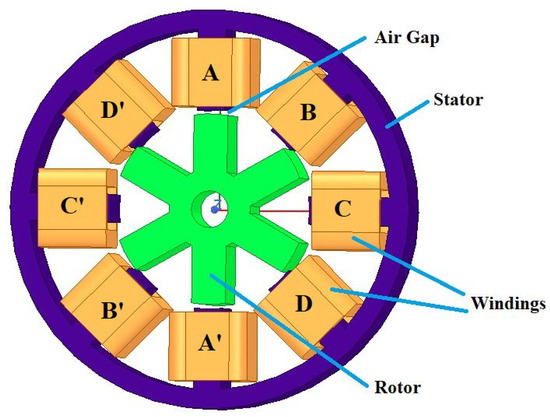
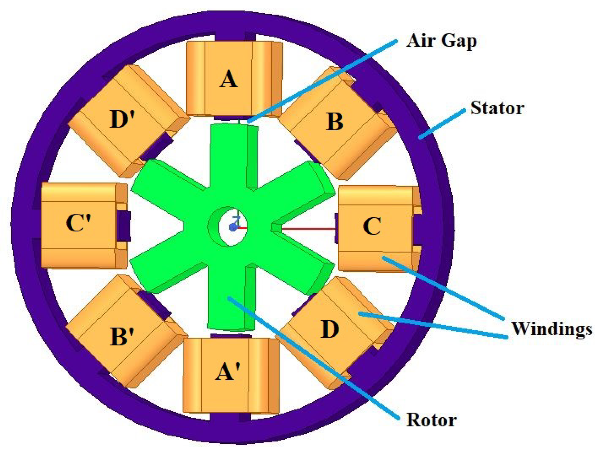
SRMs are one of the oldest electric machines, known for their simple and robust design, low manufacturing costs, and high torque output. Despite these strengths, their widespread adoption has been hindered by the complexity of their drive systems and the presence of substantial torque ripple. Advances in semiconductor technology have mitigated these problems, improved control, and reduced torque ripple, leading to wider adoption of SRMs [3]. Figure 1 shows a four-phase (A-B-C-D) 8/6 SRM. The stator has windings, while the rotor has no windings or magnets. The doubly salient structure of the motor causes high torque ripple and also leads to windage losses.
Figure 1.
8/6 SRM structure.
As seen in Equations (1) and (2), the rotor position (rad) of the SRM significantly affects the motor parameters and operating performance [3].
Here, v (V) is voltage, (rad/s) is rotor angular velocity, () denotes stator resistance, i (A) is phase current, (rad) indicates the rotor angle, (H) is the phase inductance which is a function of and i, and (Wb) is the flux linkage.
where (N.m) represents the induced torque, which is dependent on both the inductance and the current.
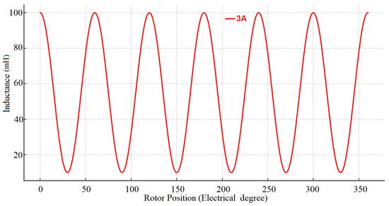
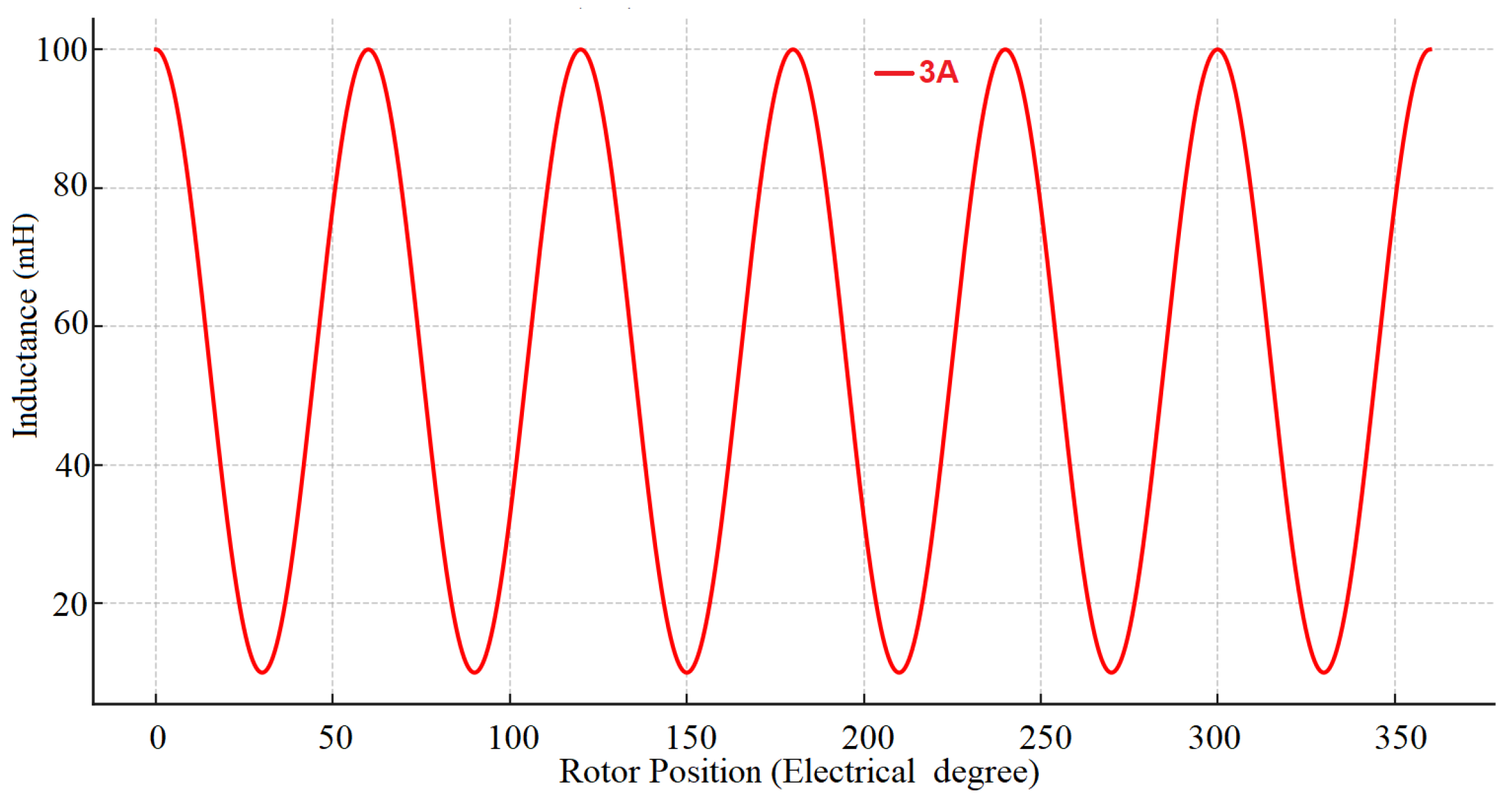
The main aim of modeling SRMs is to define the correlation of flux, current, and position of rotor. It is important to gain insight into the motor’s dynamic behavior, performance, and efficiency. Figure 2 presents a typical phase inductance profile of an SRM at a current level of 3 A over one electrical cycle, highlighting how the inductance varies with rotor position.
Figure 2.
Inductance profile of SRM.
Finite Element Analysis (FEA) and the Boundary Element Method (BEM) are widely used in SRM modeling [24].
The mathematical modeling of SRMs is computed from Maxwell’s equations, the Magnetic Equivalent Circuit (MEC) method, and Curve-Fitting (CF) methods. The MEC method is highly effective for motor analysis and design. It constructs magnetic circuits to represent the machine, enabling a detailed study of its magnetic behavior. CF techniques use lookup tables and interpolation methods. These models are typically built from a limited set of data obtained through FEA simulations or experimental measurements [25].
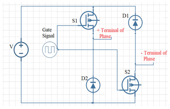
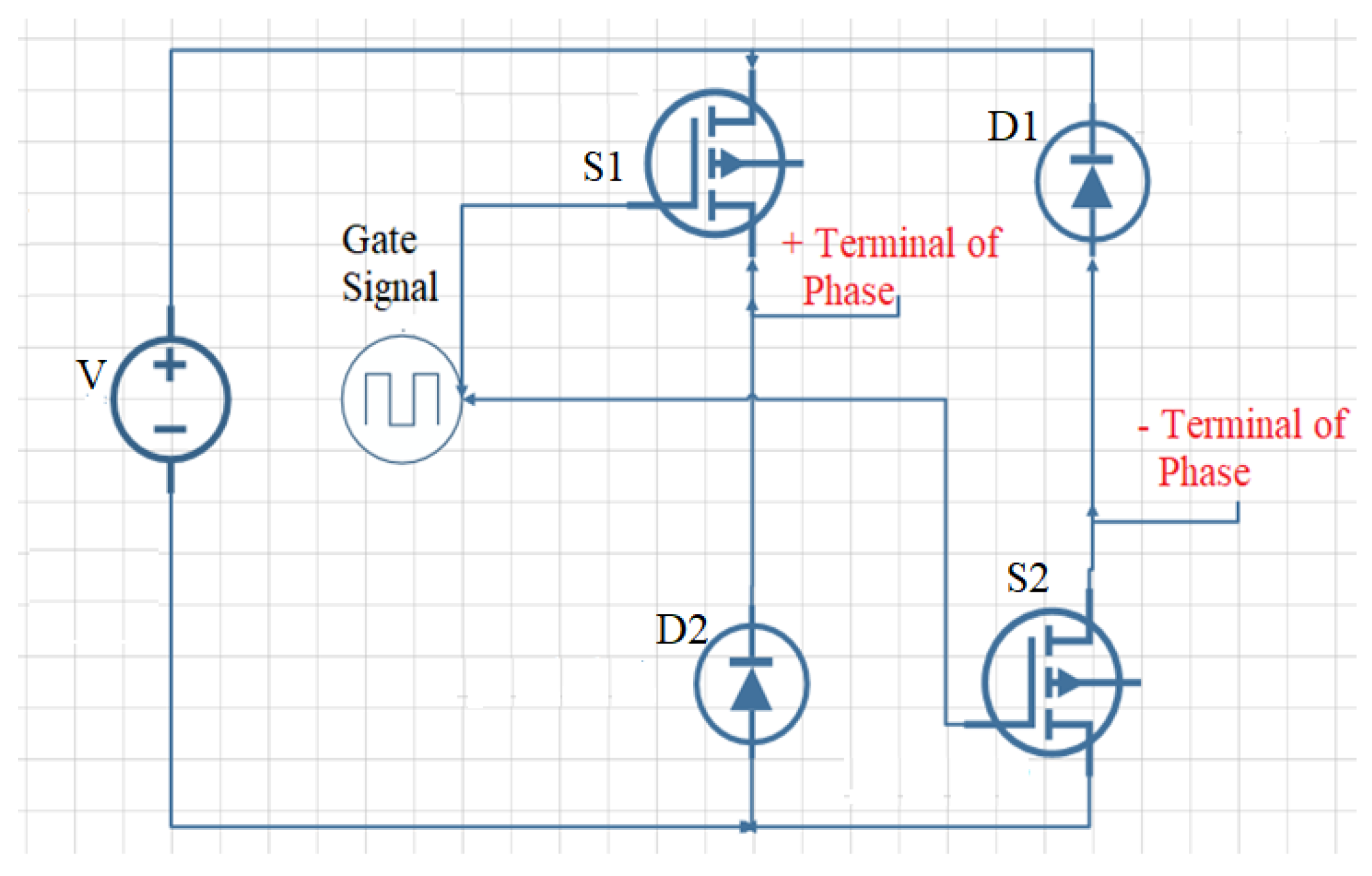
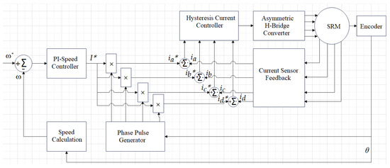
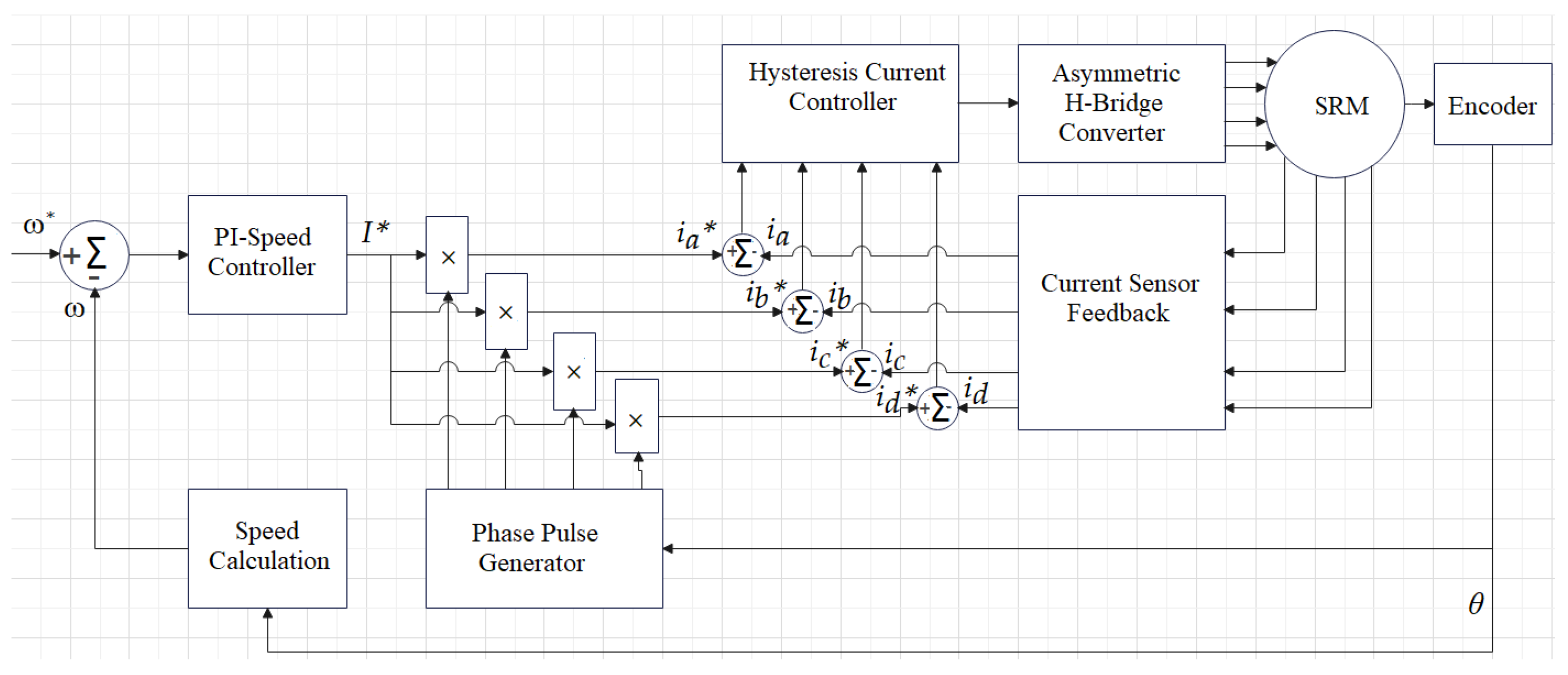
The driver circuit plays a crucial role in SRM systems. The driver circuit shown in Figure 3, applied in this work, is based on an asymmetric bridge converter topology designed in accordance with the four-phase 8/6 SRM. The converter and control circuit of the SRM used in this research are presented in in Figure 3 and Figure 4. The control architecture shown in Figure 4 employs a PI-based speed loop and a hysteresis current controller to regulate each phase current of the 8/6 SRM.
Figure 3.
Operational modes of asymmetric bridge converter.
Figure 4.
Control block diagram of SRM.
The speed error is defined as
where and represent the reference and measured rotor speeds, respectively. The PI controller processes this error, and its output determines the reference current magnitude as follows:
where and denote the proportional and integral gains of the controller. Each phase reference current , , , is compared with the measured currents, and the resulting error is fed to the hysteresis current controller. This controller generates the PWM gating signals for the asymmetric H-bridge converter.
Figure 3 shows asymmetric converter containing two switching devices , and two free-wheeling diodes , , providing drive for each phase. Here, L means as in Equation (1). The current behaviors for different switching modes are given as follows:
Magnetization mode ():
Free-wheeling mode:
Demagnetization mode ():
Here, D is PWM duty ratio.
The conduction losses are calculated as
3. Dynamics of Position Estimation
Before modeling the rotor position prediction for SRM, the rotor position needs to be analyzed. The motor’s behavior depends on its basic angular positions: , , , , . They are important for modeling flux linkage, inductance profiles, and torque generation.
- : the position where the stator pole is aligned with a rotor slot.
- : the point at which the leading edge of the stator pole aligns with the leading edge of the rotor pole.
- : the position where the stator and rotor poles are fully aligned.
- : the point where the trailing edge of the stator pole aligns with the trailing edge of the rotor pole.
- : the central alignment position of the next stator pole with a rotor slot.
From , the rotor position is a function of flux and current. This relationship is as in the equations below:
- (a)
- When , , ,When , , ,
- (b)
- When , , ,When , , ,
- (c)
- When the phase current is 0, the rotor position could be of any value [14].
4. Neural Network-Aided Approach to Rotor Position Estimation
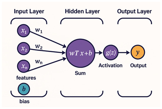
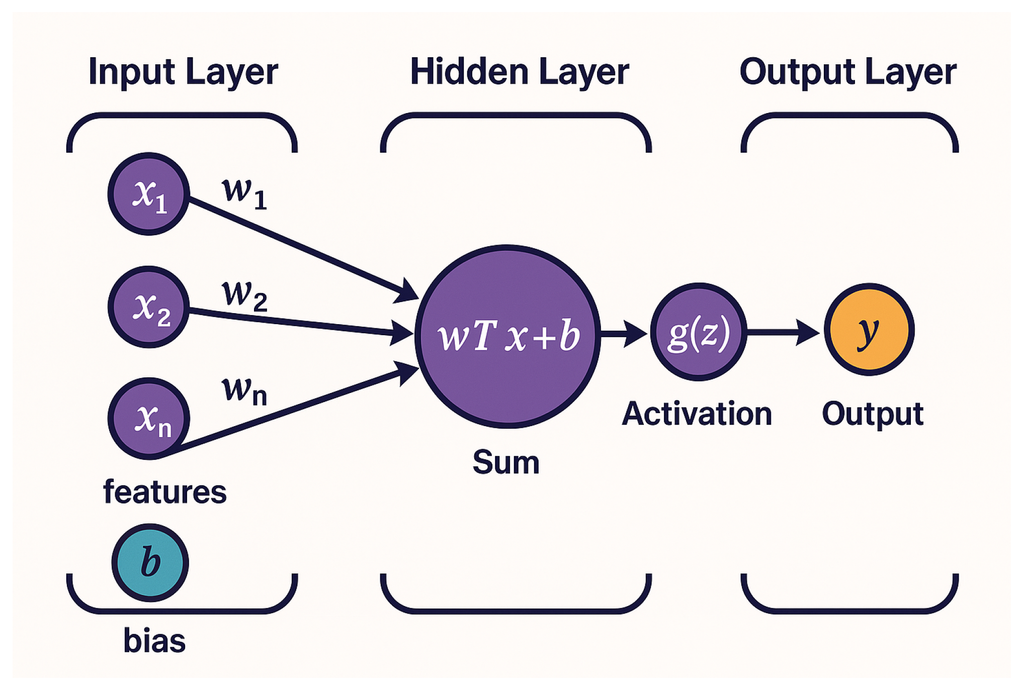
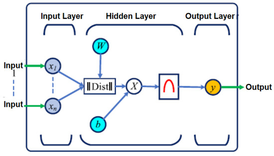
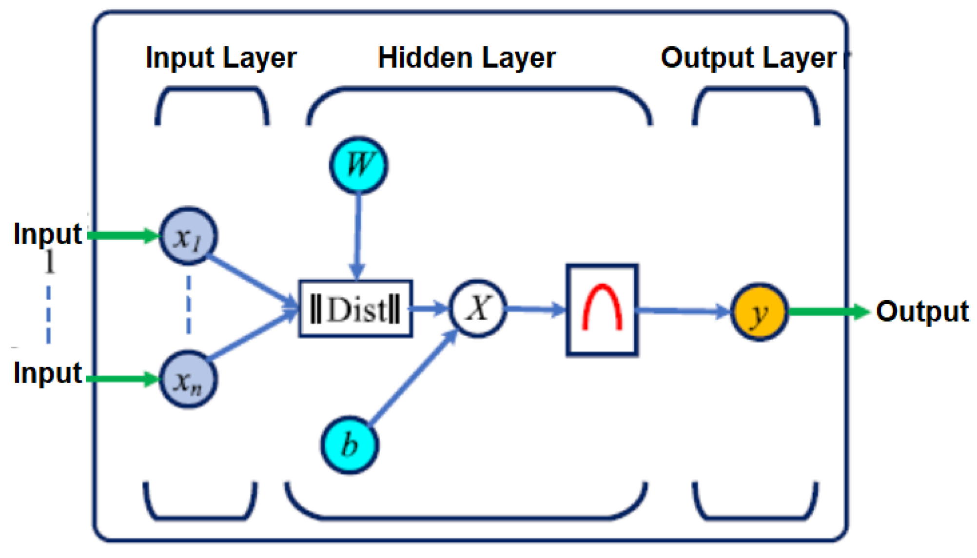
A range of algorithms, such as back-EMF, FFNN, and BPNN, are utilized in SRM modeling to achieve fast computation and high accuracy. The structures of both FFNN and BPNN models are shown in Figure 5 and Figure 6. The FFNN structure consists of layers of interconnected neurons where the data flow only in one direction as seen in Figure 5.
Figure 5.
FFNN structure.
Figure 6.
BPNN structure.
Mathematically, the FFNN process can be described as follows [26]:
Input Layer:
Weights:
Bias:
Sum:
Activation Function:
The activation function can be a non-linear function such as sigmoid or tanh.
When it is Sigmoid,
When it is Tanh,
Output Layer:
The BPNN diagram illustrates how data flow in the model. In the FFNN architecture, there are no feedback loops, and the error signal serves to refine and improve the connection parameters through the BPNN learning algorithm like in Figure 6. The BPNN learning phase can be described as consisting of two main parts: forward propagation and back propagation as follows [26]:
Forward Propagation Learning Phase:
Hidden Layer:
Output Layer:
Loss Function:
Back Propagation Learning Phase:
Output Layer Error Term:
Hidden Layer Error Term:
Weight Updates:
Bias Updates:
Choosing the right algorithm involves evaluating several factors, including its applicability to the specific task, requires accuracy, predictive capability, and overall effectiveness for the modeling purpose [27].
4.1. Rationale for Preferring the LSTM Model
Performance of the prediction model is evaluated with values as Mean Squared Error (MSE) and angle error. Previous research utilizing FFNN and BPNN models demonstrated opportunities for reducing MSE. Also, Predictive Control, Back-EMF–based estimation, and various sensorless motor control methods are reviewed and analyzed. Advanced methods yield better and more reliable results. Therefore, LSTM, which is effective in time-dependent and nonlinear models, is preferred. Furthermore, LSTM’s feedback structure enables reliable modeling of the dynamic behavior of the SRM. The magnetic state of the motor evolves over time during rotor motion and phase excitation, and the instantaneous electromagnetic behavior is influenced by previous excitation history.
4.2. Structure of LSTM
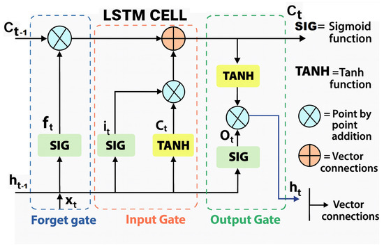
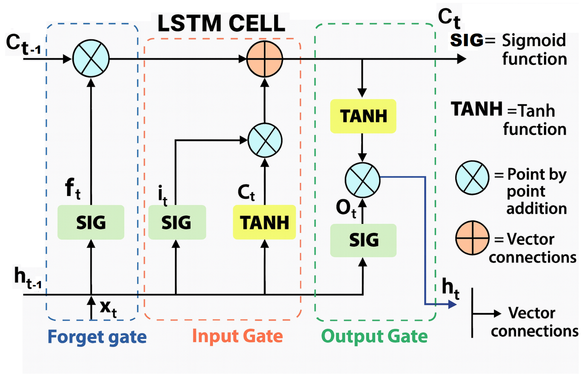
Recurrent Neural Networks (RNNs) are vital for understanding LSTM. With the development of RNN architecture, advanced RNN models that are effective in many different applications have appeared in the literature [28]. LSTM neurons replace the traditional RNN architecture by maintaining the same repeating chain structure but introducing a more complex function composed of three layers with internal self-loops that interact in a specific manner to decide which information to retain. This approach enables the network to retain prior knowledge in its memory and successfully process data sequences of varying lengths [29]. The LSTM model is shown in Figure 7. It is mostly preferred in time-series forecasting, signal processing, and control systems. LSTM architecture is a recurrent neural network approach designed to address the vanishing gradient problem encountered in classical RNN structures. LSTM architecture incorporates specialized components, namely the input gate, the forget gate, the output gate, and a memory cell that control data flow and capture long-range relations. LSTMs are widely used in applications such as time-series forecasting, signal processing, and control systems [30,31].
Figure 7.
LSTM structure.
LSTM formulas are as below: Forget Gate:
Input Gate:
Cell State Update:
Output Gate:
5. System Design and Experimental Implementation
5.1. System
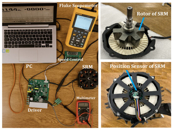
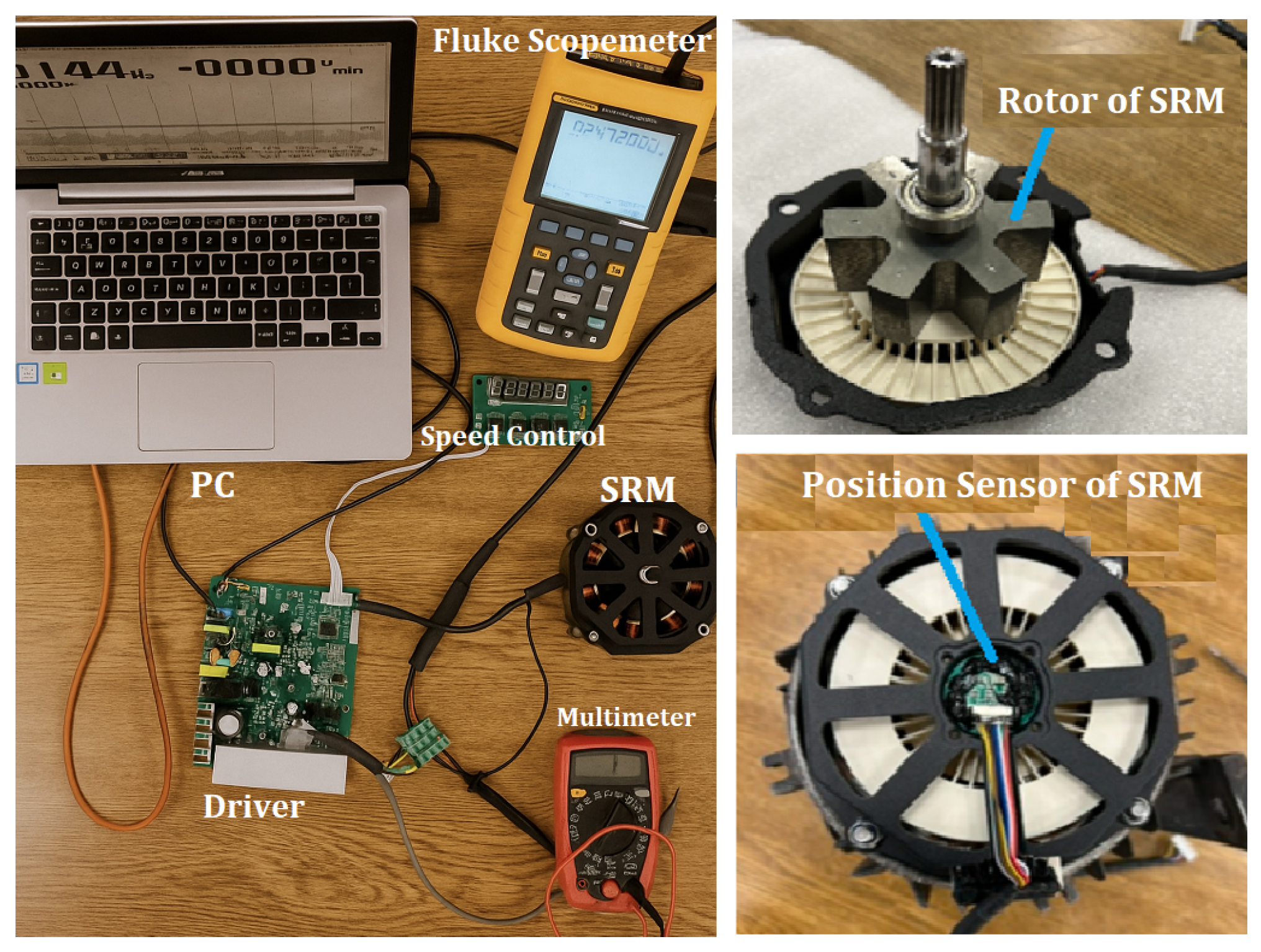
The motor was operated under different load and speed conditions to evaluate its rotor position dynamics. The experimental protocol involved both steady-state and transient operating regimes to capture a broad range of mechanical and electrical responses. The real-time motor parameter values obtained from the laboratory test setup, as shown in Figure 8, are provided in Table 1. The stack length of the motor is 60 mm. On the left side, a computer (PC) sends control signals to the motor driver, enabling operation and monitoring of system parameters. A Fluke Scope (Fluke Corporation, Everett, WA, USA) measures the electrical waveforms and operating values of the SRM. At the top right, the rotor is shown, clearly displaying its toothed structure. At the bottom right, the position sensor (Honeywell, Charlotte, NC, USA) is presented. The experimental arrangement allows simultaneous monitoring of torque, speed, and phase current waveforms, ensuring high fidelity of the collected data.
Figure 8.
SRM experimental setup.
Table 1.
SRM motor parameters.
5.2. Data Acquisition
Experimental measurements were performed using an STM32F407 (STMicroelectronics, Geneva, Switzerland) microcontroller with a sampling rate of 10 kHz. Phase currents were measured with ACS723 current sensor (Allegro Microsystems, Worcester, MA, USA), while rotor position was obtained from a 1000 PPR optical encoder. In SRM drives, phase current measurements are already required for current control and protection. In this study, external current sensors were used only for experimental measurements. Therefore, the proposed sensorless method does not require additional measurement hardware and eliminates mechanical position sensors such as encoders or resolvers, reducing system cost and complexity. All signals were digitized through a 12-bit ADC, lightly filtered, and logged synchronously for training and validation of the proposed estimator. The following signals were recorded as inputs and output. The inputs were the phase A/B/C/D currents and voltages, while the output was the rotor position in degrees measured by the SRMs. All signals were sampled at 10 kHz over a 60 s period, yielding 600,000 samples per channel. The data were organized into an 80% training set (480,000 samples) and a 20% testing set (120,000 samples) to ensure accurate model training and unbiased performance evaluation. The data were scaled between 0 and 1 and split into training, validation, and test sets without mixing different operating conditions. High-frequency noise was reduced through light preprocessing, and signals were aligned at 10 kHz. The LSTM model was trained offline in MATLAB (Software R2022a, MathWorks, Natick, MA, USA). (Intel i7, 16 GB RAM) in approximately 15 min. During online operation, the prediction time per step is about 0.3–0.8 ms, enabling real-time implementation on the STM32F407 microcontroller. The LSTM enhances robustness by learning temporal patterns that suppress local noise.
5.3. LSTM Architecture Under Study
The LSTM is among the most prominent architectures within the RNN family [32]. The variables of the implemented LSTM architecture are presented in Table 2. The input layer receives eight features (four currents and four voltages). A total of 4000 rows of current and voltage data were recorded. MSE loss function was selected to penalize large deviations between predicted and actual rotor positions. The Adam optimizer was chosen for its fast convergence and adaptive learning rate capabilities. The system was developed using the available dataset with 40 epochs and a batch size of 64, which was determined experimentally to provide a balance between convergence stability and computational efficiency [33].
Table 2.
LSTM architecture parameters.
5.4. Training and Deployment of the Model
The training was conducted on a system with adequate hardware infrastructure; the regular decrease in the loss curve revealed stable gradient transmission in the LSTM layers, which was attributed to appropriate initial weights, the Adam algorithm, and the scaling of the input data.
The LSTM architecture was selected to balance estimation accuracy and computational efficiency. Smaller models showed limited capacity, while larger ones increased complexity without significant validation gains. Therefore, the 2 × 128 structure was chosen as an effective compromise.
6. Predicting Initial Rotor Position
The rotor’s initial position has a decisive effect on the motor’s starting operation and energy efficiency. Lack of or errors in position information can lead to torque irregularities, vibrations, and performance degradation during startup. Common techniques for initial position estimation include [34]:
- -
- Magnetic field-based methods;
- -
- Back EMF analysis;
- -
- Current–voltage signal processing;
- -
- AI and machine learning techniques;
- -
- Algorithms such as Kalman Filter, Extended Kalman Filter, and Sliding Mode Observers. In this study, a short-term voltage was applied to the phases while the rotor was stationary, and the phase currents were compared based on the principle that current is inversely proportional to inductance for constant voltage and time. Thus, the initial rotor position was determined and found to be 41.31° [14].
Here, high reliability of rotor position detection is extremely important. In ref. [35], a reliable initial position detection technique for a sensorless-controlled synchronous motor is evaluated.
The low-speed region corresponds to 300 RPM, which represents the lowest achievable operating speed in the experimental setup. Therefore, a dedicated performance analysis was conducted specifically for this operating point. The obtained Mean Absolute Error (MAE) ranges between 1.46° and 1.64°, while the prediction accuracy varies between 92.26% and 92.61%.
7. Results and Discussion
The LSTM model performed highly successfully in predicting rotor position of SRM. Root Mean Squared Error (RMSE) curves, position tracking, and torque/flux performances demonstrate that the model is reliable for real-time sensorless control [36].
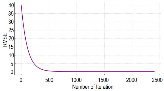
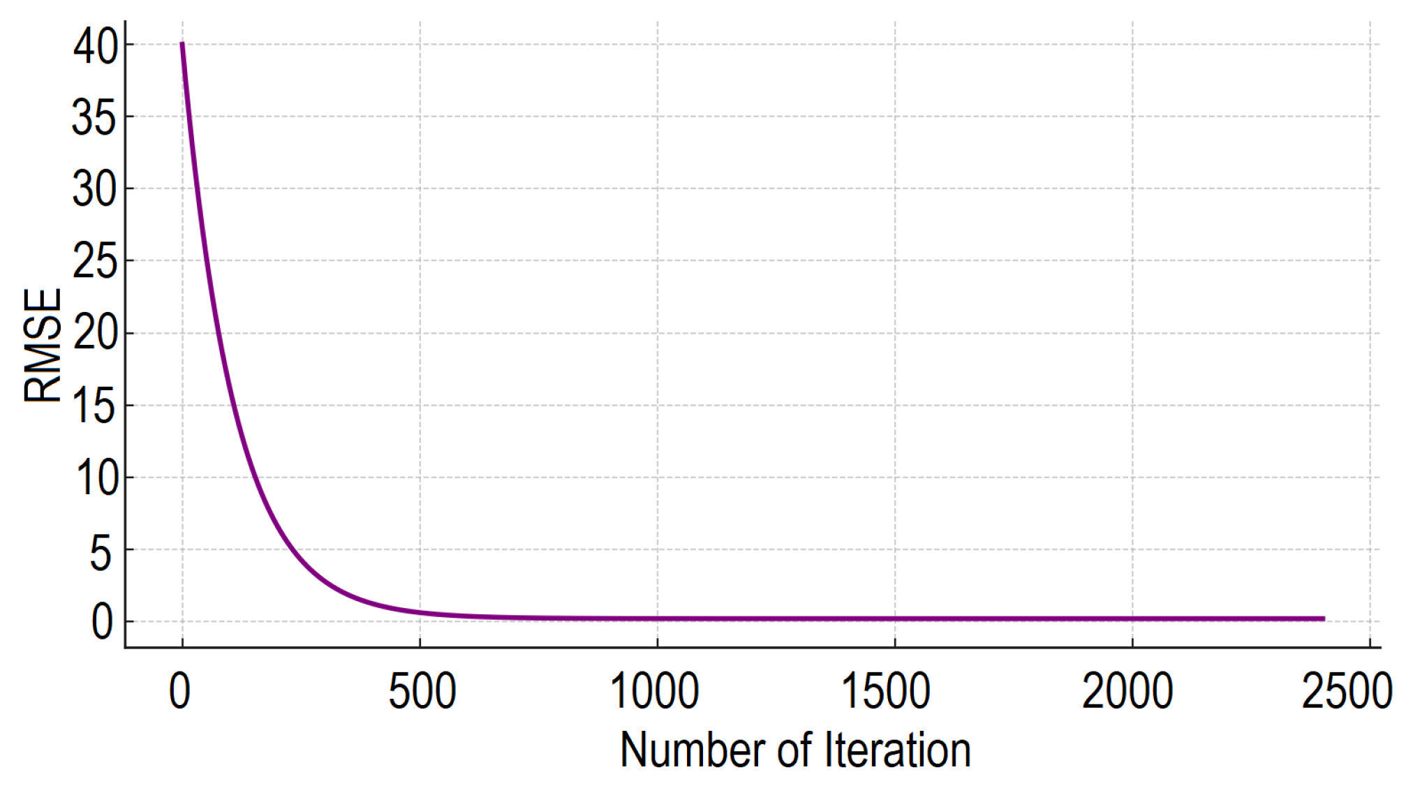
As seen in Figure 9, the RMSE drops rapidly in the first iterations, indicating that the model quickly learned the underlying patterns. Furthermore, the curve stabilizes at a low level, revealing that the LSTM model exhibits smooth convergence without uncertainty or over learning.
Figure 9.
Training progress.
The top five performance results of multiple trainings are given in Table 3. The most successful training obtained an MSE of , Mean Absolute Error (MAE) of 1.09°, and prediction value of 97.35%. MSE and RMSE formulas are like in Equations (38) and (39), respectively.
Table 3.
Model performance metrics at 1500 RPM under approximately 3 N.m load.
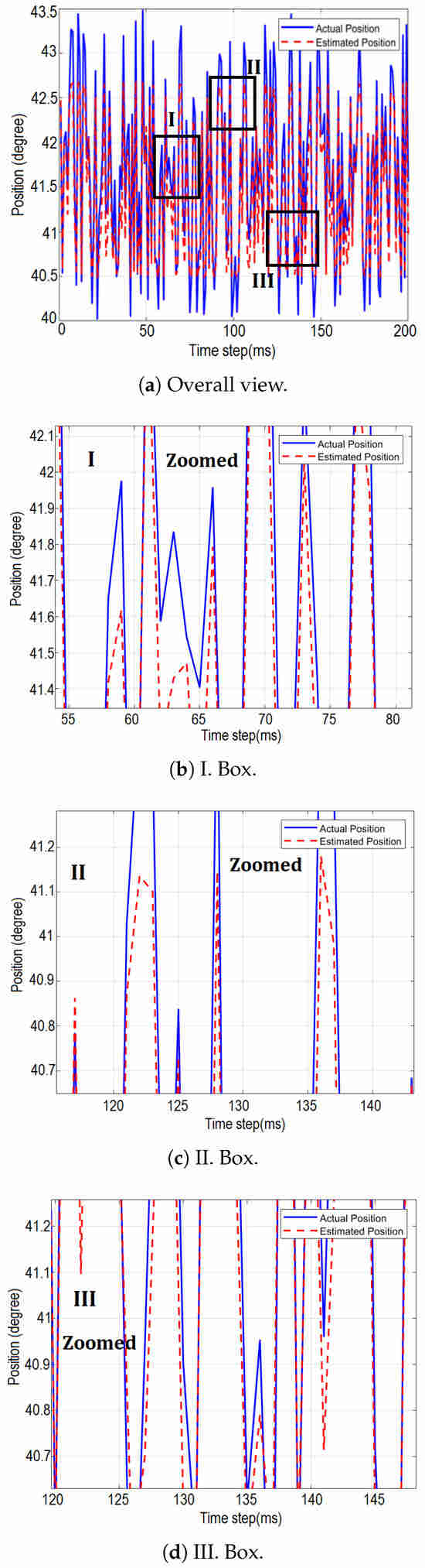
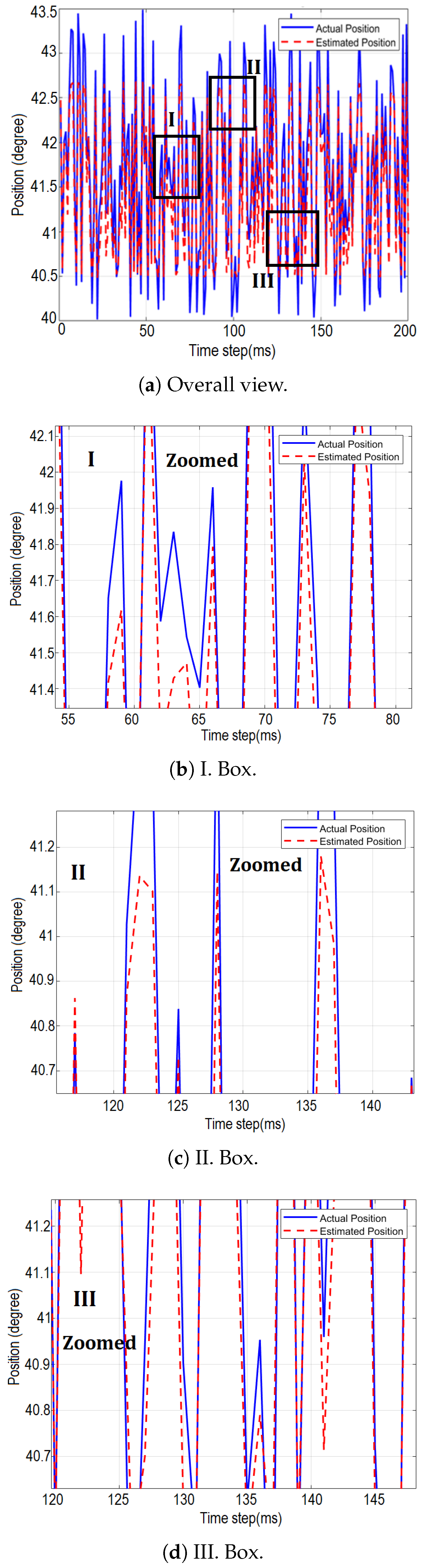
Figure 10 shows that in operating mode at 1500 RPM and a load of 3 N.m, the predicted and actual position curves exhibit very close behavior. In Figure 10b–d, which are zoomed-in sections of Figure 10a, the instantaneous deviation rarely exceeded ±2°, which is well within the tolerances required for reliable commutation in SRM drives. During speed transitions and load changes, LSTM showed no significant deterioration in prediction accuracy and proved its reliability under varying operating conditions.
Figure 10.
Rotor position estimation using LSTM.
As shown in Figure 10, the prediction performance was evaluated not only in terms of RMSE but also in terms of temporal behavior. In the fast transient regimes marked I–III, the LSTM-based estimator exhibited smooth and stable tracking. This is explained by the recurrent nature and memory mechanism of the LSTM.
The figures illustrate that the rotor position tracking error increases during transitions where current and inductance change rapidly. To reduce these deviations, expanding the training data to include these transitions and adding additional inputs to the model, such as phase voltage, will be considered in the future.
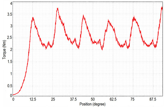
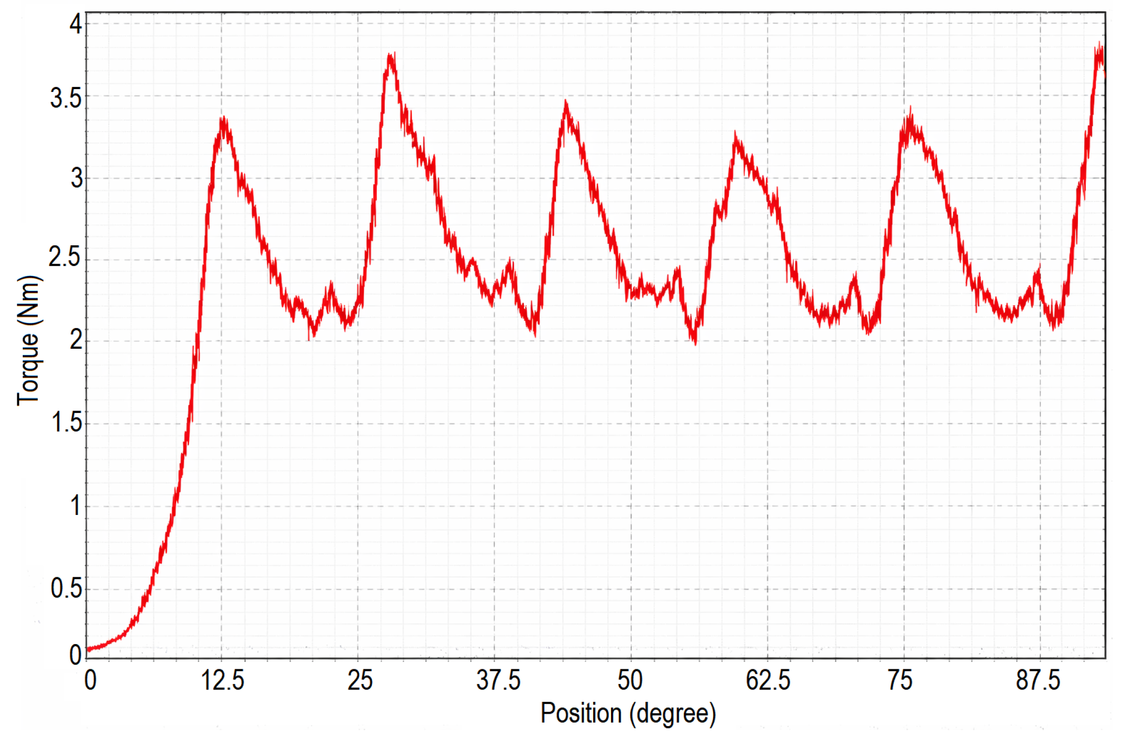
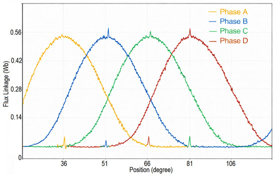
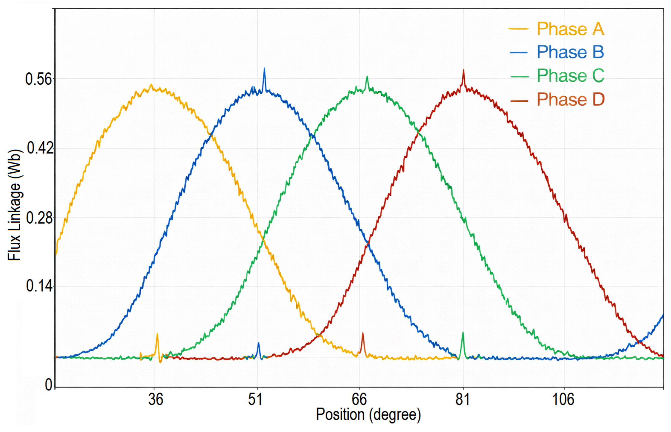
Figure 11 shows that it produces a peak torque of over 3.5 N.m for every 20° of alignment between its poles. Figure 12 illustrates the variation of flux linkage with respect to rotor position for each phase. The flux linkage reaches values above approximately 0.5 Wb near the aligned position and decreases toward zero as it approaches the unaligned position. The LSTM-based estimator tracks these nonlinear flux variations with high consistency.
Figure 11.
Torque position of SRM.
Figure 12.
Flux position of SRM.
The model was also tested under different speed-load combinations: a load of 4.9 N.m at approximately 930 RPM in Table 4 and a load of 2.48 N.m at 1780 RPM in Table 5. The motor’s nominal operating condition is defined as 1500 RPM speed and 3 N.m load. The results for this operating point are presented in Table 3. The results summarized in Table 4 and Table 5 show that the estimator maintains high accuracy under varying speed and torque levels and offers estimation performance similar to at the nominal operating point.
Table 4.
Model performance metrics at 930 RPM under approximately 4.9 N.m load.
Table 5.
Model performance metrics at 1780 RPM under approximately 2.48 N.m load.
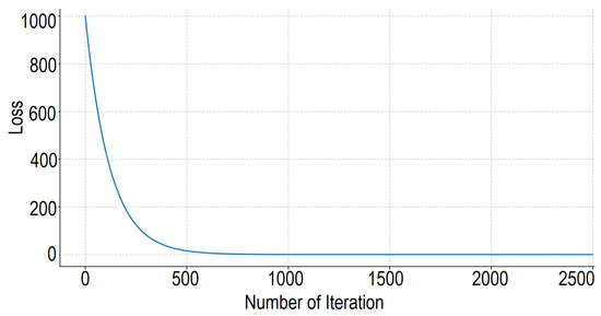
Rotor position estimation becomes more challenging at very low speeds and during start-up. At low speed (300 RPM), the rotor position changes slowly, which reduces the time variation of phase inductance and weakens the position-dependent features in the phase currents. As a result, the observable information in the current signals decreases, leading to increased estimation error. The dataset includes the complete start-up and low-speed operation within the 60 s measurement period. A total of 480,000 samples were used for training over 40 epochs (batch size 64), and the 2500 iterations shown in Figure 9 correspond to logged update steps. As indicated in Table 6, the slight increase in error at very low speeds, such as 300 rpm, is mainly attributed to the SRM’s nonlinear characteristics and reduced signal sensitivity in this region, while the LSTM still maintains acceptable accuracy.
Table 6.
Model performance metrics at 300 RPM under approximately 5.7 N.m load.
Table 7 and Table 8 present the ablation study results for a four-input LSTM model performed using only voltage and only current inputs. The results show that current data are more effective in rotor position estimation. This is theoretically consistent with the fact that inductance is dependent on current and rotor position. Compared to the full eight-input model (MAE = 1.09°), the current-only configuration increases the MAE by approximately 19%, whereas the voltage-only configuration results in an increase of about 165%. This quantitatively demonstrates that current inputs play a more significant role in rotor position estimation, while the combined use of current and voltage signals provides the best overall performance.
Table 7.
Ablation study results of the LSTM model (current only) at 1500 RPM under approximately 3 N.m load.
Table 8.
Ablation study results of the LSTM model (voltage only) at 1500 RPM under approximately 3 N.m load.
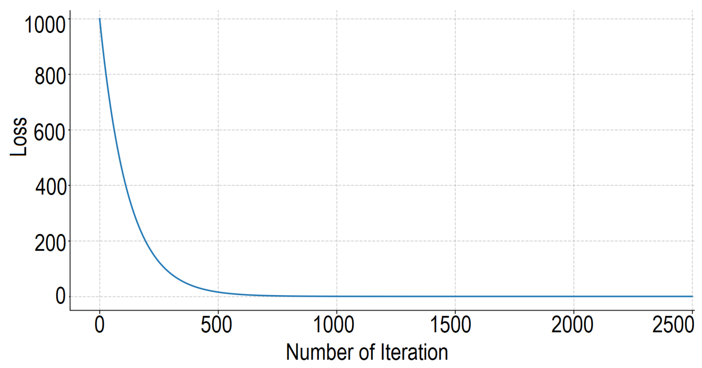
A cross-operating condition validation was conducted to assess the robustness of the proposed method. The training and testing datasets were obtained from independent experiments conducted under different load conditions using the same hardware setup. The data used across all experiments were the same. However, for the cross-operating condition generalization analysis, the model was trained and tested specifically on the unseen regime, ensuring that the experimental protocol clearly distinguishes between training and evaluation conditions. The model was trained on three operating regimes and evaluated on an unseen regime (300 rpm–5.7 N.m). The resulting MAE varied between 1.71° and 1.86°, indicating only a moderate degradation compared to the in-regime results and confirming the generalization capability of the estimator. Figure 13 provides the loss versus iteration variation of the LSTM model.
Figure 13.
Loss versus iteration.
In SRM, the commutation angle depends on the rotor position; therefore, the instantaneous position prediction error shifts the phase on–off times by the same amount. However, since torque generation occurs in the alignment region where the inductance slope is high, small position errors of the order of 1–2° outside this region do not significantly affect the average torque per phase.
The Back-EMF method was selected as a widely used and easily implementable conventional technique. Other approaches, such as flux linkage and observer-based methods, require more detailed modeling and higher implementation complexity. In Table 9, LSTM and Back-EMF are compared under the same conditions. Back-EMF was very ineffective at very low speeds. This is because, due to the absence of permanent magnets in the SRM, the back-EMF signals have low amplitude and do not carry sufficiently strong position information.
Table 9.
Comparison between LSTM and Back-EMF at 1500 RPM under approximately 3 N.m load.
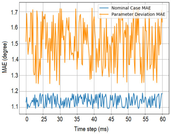
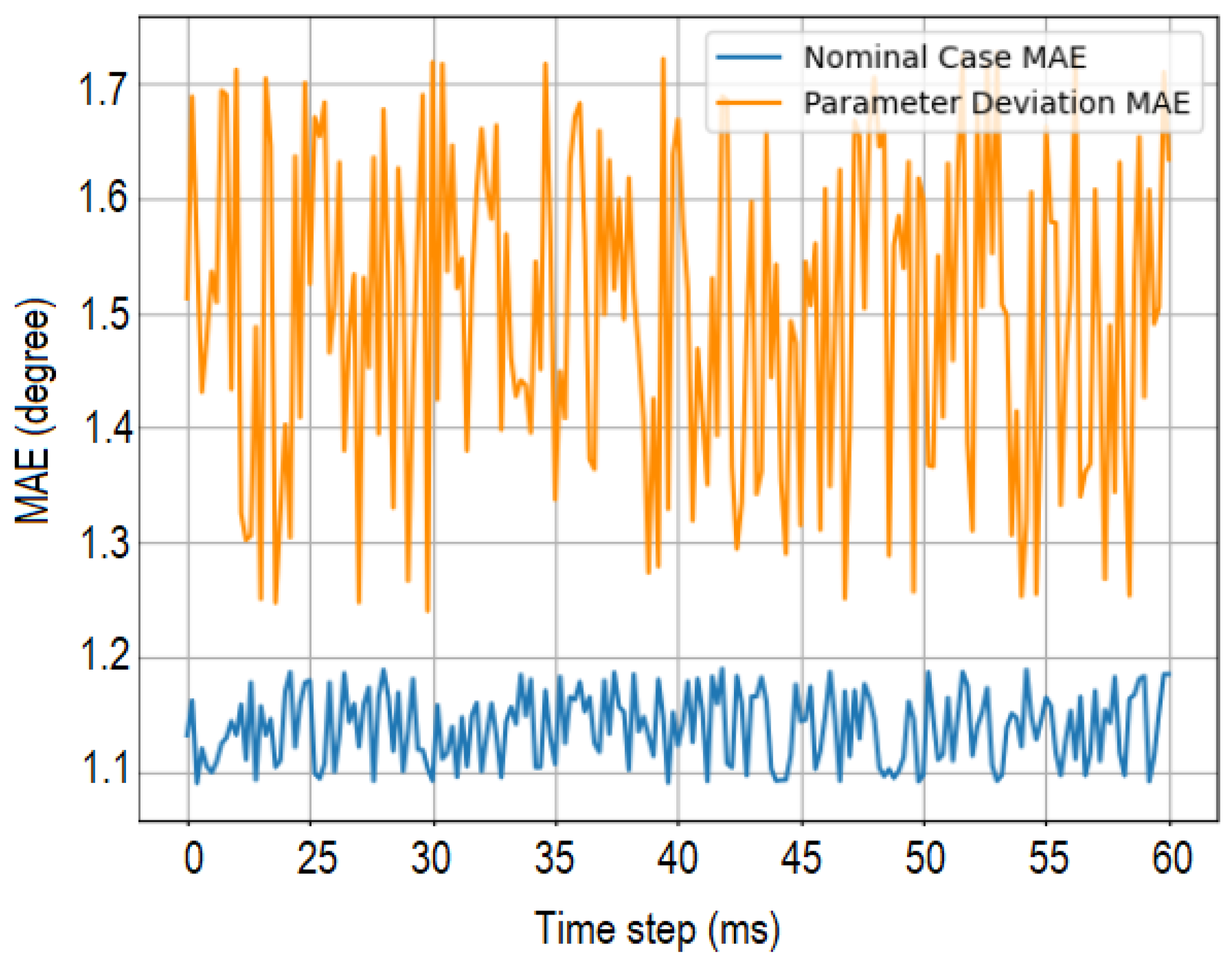
To investigate temperature effects, resistance was increased by +20% and +40%, and inductance was varied by ±20% to represent magnetic saturation and parameter uncertainties. The results are shown in the Figure 14. These findings demonstrate that the proposed LSTM estimator is stable and reliable against practical parameter variations.
Figure 14.
MAE-time graph of LSTM.
Variations in winding temperature, motor aging, or parameter scattering due to manufacturing tolerances can limit model performance. Investigating the impact of these factors and developing hybrid approaches using physics-based information will be considered in future studies.
8. Overall Evaluation
During model training, as seen in Figure 9, the RMSE decreases sharply in the first iterations and approaches stability near 0. Figure 13 illustrates the loss and iteration curves of the proposed LSTM model. As can be observed, the loss decreases steadily and converges after approximately 600 iterations indicating stable learning behavior. In Figure 10, the estimated angle closely follows the reference signal throughout the operation, with only minor deviations. Here, it was observed that the error remained within a limited range, such as below 1 degree and rose slightly to higher values in the regions where current variations occurred. The most challenging for the model to predict are generally the aligned–unaligned transitions and low speeds. Results indicate that LSTM-based sensorless rotor position estimation offers a reliable and accurate alternative to conventional sensing methods in SRMs. While the proposed LSTM estimator performs well under normal operating conditions, its behavior may differ in certain hardware-related fault scenarios. A damaged transistor can cause a phase failure that disables the motor, making rotor position estimation difficult or unsuccessful. When the faulty component is disconnected, the motor can operate with one phase missing; however, the altered inductance and reduced torque disturb the rotor position dynamics and reduce the accuracy of the LSTM estimator. For the system to function properly, the faulty transistor must be replaced with a working one. When the method is applied to other SRM types, the pole angles, torque, and inductance profile will be different. This model can also be applied to different SRM types by updating parameters such as number of phases and poles. Further studies will focus on real-time hardware implementation, where the proposed estimator will be embedded into the control loop on DSP, FPGA, or microcontroller platforms, and application of with fault-tolerant IA-based sensorless drive systems in practical applications [22].
9. Conclusions
This work proved the effectiveness of deep LSTM networks as a data-driven method for rotor position prediction in prototype SRM. The LSTM was trained with experimental data for approximately 2500 iterations and tested under different load and speed conditions such as 930 RPM–4.9 N.m, 1500 RPM–3 N.m, and 1780 RPM–2.48 N.m. While the estimation error is higher at the 300 RPM operating point, it remains close to 1 degree under most other operating conditions, particularly under nominal conditions. The criteria values determining the estimation performance of the proposed model under nominal operating conditions are MSE, 1.09° MAE, and 97.35% prediction performance. The outcomes indicate that the approach considered demonstrates consistent performance within the scenarios tested. Therefore, this technique can be considered a potential for real-time sensorless motor control applications. To further advance this work, the following goals may be planned: more different working conditions, implementing real-time applications on embedded hardware such as DSP, FPGA, STM32, and Raspberry Pi. Also, plans can include increasing robustness through hybrid solutions that combine physics-based models and data-driven techniques.
Author Contributions
Conceptualization, B.G., A.N.A. and N.F.O.S.; Methodology, B.G., A.N.A., N.F.O.S., O.T. and M.G.; Software, B.G.; Validation, B.G.; Formal analysis, A.N.A., N.F.O.S. and O.T.; Investigation, M.G.; Resources, O.T. and M.G.; Writing—original draft, N.F.O.S.; Writing—review & editing, N.F.O.S.; Supervision, A.N.A. and N.F.O.S.; Project administration, N.F.O.S. All authors have read and agreed to the published version of the manuscript.
Funding
This research was funded by the Marmara University Scientific Research Projects Unit (BAPKO) grant number 11036.
Data Availability Statement
The original contributions presented in this study are included in the article. Further inquiries can be directed to the corresponding author.
Conflicts of Interest
All authors contributed to research, the evaluation of the results, and the development of the manuscript, and approved the final version. The article has not been submitted to any other publication. None of the authors are associated with any entity that might derive monetary gain from the findings of this study.
Abbreviations and Symbols
The following abbreviations are used in this manuscript:
| Input vector; the input features to the model. | |
| n | Number of inputs (features). |
| Weight vector; weights corresponding to each input feature. | |
| b | Bias term; the model’s bias constant. |
| z | Weighted sum of inputs plus bias (pre-activation value). |
| Output after activation function (activation value). | |
| Activation function (e.g., sigmoid, tanh). | |
| Model output (predicted value). | |
| e | Mathematical constant, approximately 2.71828 (base of natural logarithm). |
| Hyperbolic tangent activation function. | |
| Pre-activation sums. | |
| Activation output of the initial hidden layer. | |
| Weight matrices. | |
| Bias vectors. | |
| L | Loss function; measures error between predicted and true output. |
| y | True (target) output value. |
| Error terms in the first and second layers. | |
| ∘ | Element-wise multiplication (Hadamard product). |
| Derivatives of activation functions used in Back Propagation. | |
| Training coefficient; specifies the adjustment scale applied to | |
| model parameters. | |
| ← | Update operation, e.g., . |
| Sigmoid activation function: . | |
| Forget gate vector at time t. | |
| Input gate vector at time t. | |
| Candidate cell state vector at time t. | |
| Cell state vector at time t; memory of the network. | |
| Cell state vector at previous time step . | |
| Output gate vector at time t. | |
| Hidden state (output) vector at time t. | |
| Weight matrices for forget, input, candidate cell, and output gates respectively. | |
| Bias vectors for forget, input, candidate cell, and output gates respectively. | |
| Hidden state vector from previous time step . | |
| Input vector at time step t. |
References
- Husain, I. Minimization of torque ripple in SRM drives. IEEE Trans. Ind. Electron. 2022, 49, 28–39. [Google Scholar] [CrossRef] [Scilit]
- Gan, C.; Wu, J.; Sun, Q.; Kong, W.; Li, H.; Hu, Y. A review on machine topologies and control techniques for low-noise switched reluctance motors in electric vehicle applications. IEEE Access 2018, 6, 31430–31443. [Google Scholar] [CrossRef] [Scilit]
- Gecer, B.; Serteller, N. Understanding switched reluctance motor analysis using ANSYS/Maxwell. In Proceedings of the IEEE International Symposium on Industrial Electronics (ISIE), Delft, The Netherlands, 17–19 June 2020. [Google Scholar] [CrossRef] [Scilit]
- Young, C. Modified PWM Direct Instantaneous Torque Control System for SRM. Math. Probl. Eng. 2021, 2021, 1158360. [Google Scholar] [CrossRef] [Scilit]
- Tokui, K.; Kumagai, T.; Itoh, J.I. Torque ripple suppression method based on FOC for SRM without FEM analysis. In Proceedings of the 23rd European Conference on Power Electronics and Applications (EPE’21 ECCE Europe), Ghent, Belgium, 6–10 September 2021. [Google Scholar] [CrossRef] [Scilit]
- Wang, Q.; Wang, S.; Chen, C. Review of sensorless control techniques for PMSM drives. IEEJ Trans. Electr. Electron. Eng. 2019, 14, 1543–1552. [Google Scholar] [CrossRef] [Scilit]
- Xiao, D.; Rotilli Filho, S.; Fang, G.; Ye, J.; Emadi, A. Position-sensorless control of switched reluctance motor drives: A review. IEEE Trans. Transp. Electrif. 2022, 8, 1209–1227. [Google Scholar] [CrossRef] [Scilit]
- Kim, T.; Lee, H.W.; Ehsani, M. Position sensorless brushless DC motor/generator drives: Review and future trends. IET Electr. Power Appl. 2007, 1, 557–564. [Google Scholar] [CrossRef] [Scilit]
- Pradeep, A.K.; Lyons, J.P.; MacMinn, S.R. Application of sliding mode observers for state estimation in rotating machines. Proc. VARSCON’91 1991, 57–64. [Google Scholar]
- Gao, H.; Salmasi, F.; Ehsani, M. Inductance model-based sensorless control of switched reluctance motor drive at low speed. IEEE Trans. Power Electron. 2004, 19, 1568–1573. [Google Scholar] [CrossRef] [Scilit]
- Lyons, J.; MacMinn, S.; Preston, M. Flux/current methods for SRM rotor position estimation. In Proceedings of the IEEE IAS Annual Meeting, Dearborn, MI, USA, 28 September–4 October 1991; pp. 482–487. [Google Scholar]
- Mese, E.; Torrey, D. Sensorless position estimation for variable-reluctance machines using artificial neural networks. In Proceedings of the IEEE IAS Annual Meeting, New Orleans, LA, USA, 5–9 October 1997; pp. 540–547. [Google Scholar]
- Cheok, A.; Ertugrul, N. High robustness and reliability of fuzzy-logic-based position estimation for sensorless switched reluctance motor drives. IEEE Trans. Power Electron. 2000, 15, 319–334. [Google Scholar] [CrossRef]
- Cai, Y.; Wang, Y.; Xu, H.; Sun, S.; Wang, C.; Sun, L. Research on rotor position model for switched reluctance motor using neural network. IEEE/ASME Trans. Mechatron. 2018, 23, 2762–2773. [Google Scholar]
- Fan, J.; Lee, Y. Sensorless control of switched reluctance motor based on a simple flux linkage model. Electr. Eng. Electromech. 2023, 2023, 36–39. [Google Scholar] [CrossRef] [Scilit]
- Ni, F.; Zhang, W.; Bi, Y.; Li, B. The Study of SRM Sensorless Control Strategy Based on SOGI-FLL and ADRC-PLL Hybrid Algorithm. Electronics 2023, 13, 2. [Google Scholar] [CrossRef] [Scilit]
- Qi, B.; Liang, J. A comparative study of BPNN, CNN, and LSTM neural network models for nuclear power plant accident diagnosis. Trans. Am. Nucl. Soc. 2021, 124, 406–409. [Google Scholar]
- Yalavarthi, A.; Singh, B. Sensorless speed control of SRM drive using optimized neural network model for rotor position estimation. IEEE Trans. Energy Convers. 2024, 39, 2158–2168. [Google Scholar] [CrossRef] [Scilit]
- Omar, M.; Sayed, E.; Abdalmagid, M.; Bilgin, B.; Bakr, M.H.; Emadi, A. Review of machine learning applications to the modeling and design optimization of switched reluctance motors. IEEE Access 2022, 10, 130444–130468. [Google Scholar] [CrossRef] [Scilit]
- Ge, L.; Liu, H.; Du, N.; Sun, G.; Meng, T.; Li, L.; Song, S. Sensorless Control of Switched Reluctance Motor Based on Improved Particle Filter. IEEE Trans. Ind. Electron. 2025, 73, 275–283. [Google Scholar] [CrossRef] [Scilit]
- Dong, J.; Sun, L.; Chen, L. Sensorless Control of Permanent Magnet Synchronous Motors Using LSTM-Enhanced Extended Kalman Filtering. In Proceedings of the 2025 IEEE 12th International Symposium on Sensorless Control for Electrical Drives (SLED), Harbin, China, 15–17 August 2025. [Google Scholar] [CrossRef] [Scilit]
- Singh, S.; Singh, S.N.; Tiwari, A.N. PMSM Drives and its Application: An Overview. Recent Adv. Electr. Electron. Eng. 2022, 16, 4–16. [Google Scholar] [CrossRef] [Scilit]
- Radun, A.V. High Power Density Switched Reluctance Motor Drive for Aerospace Applications. IEEE Trans. Ind. Appl. 1992, 28, 113–119. [Google Scholar] [CrossRef] [Scilit]
- Hameyer, K.; Belmans, R. Numerical Modelling and Design of Electrical Machines and Devices; KUL Press: Leuven, Belgium, 1999. [Google Scholar]
- Watthewaduge, G.; Sayed, E.; Emadi, A.; Bilgin, B. Electromagnetic modeling techniques for switched reluctance machines: State of the art review. IEEE Open J. Ind. Electron. Soc. 2020, 1, 218–334. [Google Scholar] [CrossRef] [Scilit]
- Akpolat, A.; Dursun, E.; Kuzuoğlu, A. Deep learning-aided sensorless control approach for PV converters in DC nanogrids. IEEE Access 2021, 9, 106641–106654. [Google Scholar] [CrossRef] [Scilit]
- Anders, U.; Korn, O. Model selection in neural networks. Neural Netw. 2000, 12, 309–323. [Google Scholar] [CrossRef] [Scilit]
- Giles, C.L.; Kuhn, G.M.; Williams, R.J. Dynamic recurrent neural networks: Theory and applications. IEEE Trans. Neural Netw. 1994, 5, 153–156. [Google Scholar] [CrossRef] [Scilit]
- Zhang, J.; Zhu, Y.; Zhang, X.; Ye, M.; Yang, J. Developing an LSTM-based model for predicting water table depth in agricultural areas. J. Hydrol. 2018, 561, 918–929. [Google Scholar] [CrossRef] [Scilit]
- Al-Selwi, S.M.; Hassan, M.F.; Abdulkadir, S.J.; Muneer, A.; Sumiea, E.H.; Alqushaibi, A.; Ragab, M.G. RNN-LSTM: From applications to modeling techniques and beyond—Systematic review. J. King Saud Univ.-Comput. Inf. Sci. 2024, 36, 102068. [Google Scholar] [CrossRef] [Scilit]
- Yu, Y.; Zhang, J.; Hu, C.; Zhang, J. A review of recurrent neural networks: LSTM cells and network architectures. Neural Comput. 2019, 31, 1235–1270. [Google Scholar] [CrossRef] [Scilit]
- Zhang, W.; Guo, W.; Liu, X.; Liu, Y.; Zhou, J.; Li, B.; Lu, Q.; Yang, S. LSTM-based analysis of industrial IoT equipment. IEEE Access 2018, 6, 23551–23560. [Google Scholar] [CrossRef] [Scilit]
- Burgueño, L.; Cabot, J.; Gerard, S. An LSTM-based neural network architecture for model transformations. In Proceedings of the 2019 ACM/IEEE International Conference on Model Driven Engineering Languages and Systems (MODELS), Munich, Germany, 15–20 September 2019. [Google Scholar]
- Holczer, A.; Freijedo, F.D.; Bojoi, R. Overview of sensorless control strategies for electric vehicle traction IPMSM. In Proceedings of the 2023 IEEE WEMDCD, Newcastle upon Tyne, UK, 13–14 April 2023. [Google Scholar] [CrossRef] [Scilit]
- Shi, X.; Liu, T.; Mu, W.; Zhao, J. High-Reliability Rotor Position Detection Method for Sensorless Control of Synchronous Condenser. World Electr. Veh. J. 2023, 14, 299. [Google Scholar] [CrossRef] [Scilit]
- Aydogmus, O.; Boztas, G. Deep learning-based approach for speed estimation of a PMa-SynRM. In Proceedings of the 11th International Conference on Electrical and Electronics Engineering (ELECO), Bursa, Turkey, 28–30 November 2019. [Google Scholar]

Disclaimer/Publisher’s Note: The statements, opinions and data contained in all publications are solely those of the individual author(s) and contributor(s) and not of MDPI and/or the editor(s). MDPI and/or the editor(s) disclaim responsibility for any injury to people or property resulting from any ideas, methods, instructions or products referred to in the content. |
© 2026 by the authors. Licensee MDPI, Basel, Switzerland. This article is an open access article distributed under the terms and conditions of the Creative Commons Attribution (CC BY) license.