


Abstract
Carbon fibre reinforced polymers (CFRPs) are increasingly used in biomedical and safety-critical applications, where embedded and real-time non-destructive testing (NDT) is essential to ensure structural integrity. This paper presents a cost-effective, AI-assisted thermographic inspection system designed from an embedded electronics and circuit-level perspective. The proposed platform integrates a long-wave infrared (LWIR) sensor, dedicated signal conditioning and power management circuits, and a Raspberry Pi-based processing unit within a unified hardware–software co-design approach. Infrared data acquired under surface heating conditions are processed on-board using a convolutional neural network based on a U-Net architecture, enabling automatic localisation and classification of subsurface defects in CFRP samples. Particular attention is devoted to embedded design constraints, including sensor interfacing, acquisition timing, end-to-end latency, and real-time processing scalability. Experimental results confirm the feasibility of real-time surface heat assessment and the robustness of the proposed architecture in detecting delaminations and voids. The presented system contributes to the development of intelligent embedded inspection electronics and provides a reference design for edge AI-enabled NDT systems in industrial and biomedical applications.
1. Introduction
Carbon fibre reinforced polymers (CFRPs) represent one of the most significant developments in modern materials engineering due to their high stiffness-to-weight ratio, low density and distinctive thermal properties [1]. CFRPs are intrinsically anisotropic materials composed of high-conductivity carbon fibres embedded in a polymer matrix characterised by significantly lower thermal diffusivity [2]. The typical stacking configuration (e.g., [0/90/0/90]) introduces directional thermal behaviour, where the in-plane conductivity along the fibre direction (x-axis) significantly differs from the in-plane transverse direction (y-axis), while the conductivity through the thickness (z-axis) is considerably lower. The resulting structure exhibits strong anisotropy due to the fibre orientation and stacking sequence [3]. In laminated configurations, defects commonly occur during production or service loading. The most typical defect mechanisms include interlaminar delamination caused by impacts or cyclic fatigue, resin-rich zones, fibre waviness, and voids generated by imperfect resin impregnation [4]. Moreover, such defects alter the local thermal diffusion paths, producing temperature gradients that can be captured by long-wave infrared (LWIR) detection [5]. Delaminations typically occur at the interfaces of layers and can range from sub-millimetre to several millimetres in diameter, while cavities and porosity are often distributed within the matrix phase [6]. The detectability of these defects strongly depends on their depth, size, and thermal contrast relative to the surrounding laminate. Carbon fibres exhibit excellent mechanical strength, dimensional stability and resistance to cyclic loading, and they are typically combined with a polymeric matrix that is ductile, manufacturable and geometrically versatile [7,8]. For these reasons, CFRPs have been widely adopted in aeronautical, automotive and sporting goods applications. In recent years, increasing attention has been directed toward their use in biomechanics and biomedical engineering, where safety, durability and patient comfort are essential requirements [9,10]. In the biomedical field, CFRPs are employed in advanced prostheses, customised orthopaedic implants, braces and rehabilitation devices [11,12]. The low weight of these materials reduces mechanical load on joints and surrounding tissues, improving comfort and lowering the risk of fatigue or secondary injuries. Their adjustable stiffness, obtained through fibre orientation and volume fraction control, allows designers to tailor mechanical behaviour to mimic that of biological tissues [13]. For instance, CFRP-based lower-limb prostheses not only reduce mass compared to metallic solutions but also provide a more natural dynamic response during gait, significantly improving patients’ quality of life [14]. In addition, the intrinsic radio transparency of CFRPs enables postoperative imaging without artefacts, as these materials do not interfere with standard diagnostic modalities. A further key innovation is the possibility of embedding sensors and smart monitoring systems directly into CFRP structures, opening the way to so-called “intelligent” biomedical devices [15,16]. Such systems can monitor deformations, stresses and temperature variations in real time, ensuring continuous assessment of structural integrity and functional performance [17,18,19]. The ability to tailor anisotropic properties also enables simultaneous control of both mechanical and thermal behaviour, allowing application-specific optimisation for each patient [20,21]. However, the structural complexity of CFRPs and their strongly anisotropic thermal behaviour introduce major challenges in integrity monitoring, especially for biomedical devices where early detection of failure is critical for patient safety. Heat conduction, diffusion, thermal capacity and dimensional stability directly affect both the reliability and durability of carbon-based implants and prostheses. For this reason, thermal characterisation and monitoring of CFRPs play a central role in current research [22,23]. Recent studies have demonstrated that active infrared thermography can detect internal defects, inclusions and porosity in laminates by exploiting differences in conductivity and diffusivity between sound and damaged regions [24,25,26]. The strong anisotropy of CFRPs, with thermal conductivity along the fibres significantly higher than in the transverse direction, has been highlighted as a key factor in thermal analysis [27,28]. Lock-in thermography techniques have therefore been developed to map diffusivity and conductivity in composite laminates, enabling correlations between microstructure and macroscopic properties [29,30]. Other approaches based on line-laser thermography have been proposed to detect surface and subsurface defects in unidirectional epoxy laminates [31,32]. Thermophysical investigations have confirmed that fibre fraction and orientation strongly influence thermal diffusivity [33]. Despite these advances, thermography alone still exhibits limitations in detecting deep defects and in handling complex geometries typical of biomedical components [34]. Enhancing through-thickness conductivity using graphene- or SiC-based nanostructures has been shown to improve sensitivity to deep anomalies [35,36], while multiscale models of thermal diffusivity and conductivity have been introduced to account for fibre volume fraction and temperature effects [37]. Non-destructive testing (NDT) techniques applied to CFRPs offer speed and non-invasiveness, but they still face difficulties in real biomedical environments with curved and multilayer structures [38,39]. More recently, the integration of deep learning with thermographic imaging has significantly improved defect detection accuracy, even on complex laminates and anatomical shapes [40,41]. Physics-driven neural networks have also been proposed to combine material knowledge with data-driven inference for defect and diffusivity estimation [42]. Nonetheless, most existing approaches rely on offline analysis and manual interpretation of thermograms, which are operator-dependent and unsuitable for automated or real-time assessment. From an electronics and embedded systems perspective, a further limitation is the lack of integrated solutions that combine sensing, signal conditioning, processing and AI-based inference within a single portable architecture [43]. While algorithms and materials have been extensively studied, circuit-level design and hardware–software co-design aspects—such as sensor interfacing, power management, real-time constraints and edge computing—have received much less attention in the context of CFRP thermographic monitoring [44,45]. This work addresses these gaps by developing a low-cost, real-time embedded system for thermographic inspection of CFRP components in rehabilitation and biomedical applications.
The proposed platform integrates infrared sensing, signal processing and deep learning segmentation within a unified architecture. Active thermographic sequences are acquired and automatically processed using a CNN U-Net model running on an embedded edge device. To the authors’ knowledge, this work represents one of the first end-to-end implementations that explicitly addresses circuit-level design, hardware–software co-design, and embedded deep learning inference for real-time thermographic inspection of CFRP components within a single autonomous platform. The proposed approach enables automated, scalable inspection directly on prostheses and rehabilitation tools, overcoming limitations related to complex geometry, defect depth and real-time operation that have not yet been fully addressed in the literature. Furthermore, the concept of “circuit” in this study refers to the explicit design and optimisation of sensor interfacing, power regulation, signal integrity, temporal synchronisation, and the implementation of integrated AI at the printed circuit board level and hardware integration.
2. Materials and Methods
The thermographic data acquisition protocol, the procedures for preparing the defects, and the spatial and temporal features, along with the deep learning segmentation approach, are discussed. The proposed experimental and computational approach for the non-destructive thermographic inspection of CFRPs is based on physical modelling of the heat diffusion process, image analysis, and deep learning segmentation in this section.
The CFRP samples used, as shown in Figure 1a, have a rectangular geometry, measuring 150 × 100 mm, and a thickness of 3 mm, with a quasi-isotropic laminate configuration obtained using bidirectional twill woven carbon fabric plies. The fibre orientation within each ply follows the intrinsic 0°/90° weave pattern of the twill fabric, while the laminate stacking ensures overall quasi-isotropic in-plane behaviour. Artificial delaminations are introduced by inserting 100 µm thick PTFE films between selected layers during lamination.
Figure 1.
CFRP sample: (a) the intact sample; (b) the sample after controlled impact.
Vacuum defects were generated by locally reducing the vacuum pressure during polymerisation, as shown in Figure 1b. Low-energy impact damage was produced using a calibrated drop test with an impact energy of 5 J to simulate realistic interlaminar delamination.
Figure 1 clarifies the test configuration, where the artificial defects have lateral dimensions ranging from 5 to 20 mm. For delamination-type anomalies, an equivalent diameter of approximately 12–18 mm was observed, located at depths between 0.5 and 1.5 mm below the surface of the composite. The dimensions described above correspond to the typical failure modes of composite materials used in biomedical applications. These defects locally hinder the flow of heat, thereby reducing the thermal diffusivity of the component, making them appropriate targets for thermographic inspection.
The fundamental principles of infrared thermography and heat transfer are introduced in anisotropic composite materials [46,47]. Next, the experimental setup for thermal excitation and infrared data acquisition is described. Methods for thermal contrast enhancement and spatio-temporal feature extraction are presented immediately afterwards. A U-Net CNN architecture for automatic pixel-level defect segmentation is then described in detail. Finally, the integrated hardware–software implementation for real-time inspection on a low-cost edge computing platform is discussed, with a focus on circuit-level integration and hardware–software co-design.
2.1. Principles of Thermographic Inspection
Infrared thermography (IRT) uses natural thermal radiation to capture thermograms emitted by an object or surface with a temperature above absolute zero. Infrared sensors determine the temperature of a target by converting its heat into a measurable electrical signal. The heat emission of a body, governed by Planck’s law of radiation (1), expresses spectral radiance L (λ, T) of a blackbody at temperature T.
where L (λ, T) is the spectral radiance (W·m−2·sr−1·µm−1), h is Planck’s constant (6.626 × 10⁻³⁴ J∙s), c is the speed of light in a vacuum (2.998 × 10⁸ m/s), kB is Boltzmann’s constant (1.381 × 10⁻²³ J/K), λ is the wavelength (m), and T is the absolute temperature (K). The integration of L (λ, T) over all wavelengths gives Stefan–Boltzmann’s law, which expresses the total thermal power radiated by a black body surface (2)
where M(T) is the total emissivity (W·m−2) and σ = 5.6704 × 10⁻⁸ (W/m2∙K4) is the Stefan–Boltzmann constant. The wavelength at which the radiation reaches its maximum value is determined by Wien’s displacement law (3)
The report (3) shows that, for typical temperatures of composite materials at room temperature (T ≈ 300 K), the maximum radiation is around λmax ≈ 9.6 μm, i.e., within the long-wave infrared (LWIR) window. CFRPs deviate from ideal blackbody behaviour, since their surface emissivity ε (λ, θ) depends on wavelength (λ), observation angle (θ), fibre orientation, and surface morphology. The real radiative exitance of the material is therefore expressed as (4)
and the measured radiance reaching the infrared detector becomes (5)
where τa(λ) represents the spectral transmittance of the surrounding medium (typically air) and Lamb the contribution of ambient radiance. In CFRPs, surface emissivity is typically in the range 0.85 ≤ ε ≤ 0.95 in the LWIR band, allowing for an accurate estimate of temperature under the assumption of grey body behaviour. However, due to the anisotropic microstructure, consisting of alternating layers of carbon fibres and epoxy resin, the emissivity shows a directional dependence along the fibre axes. Anisotropy also affects thermal conduction properties, and the effective thermal conductivity tensor is defined in Equation (6).
where kx is the conductivity parallel to the carbon fibres and ky is that perpendicular to them. The thermal conductivity tensor is defined in the material reference coordinate system as kx, ky, kz, where the x-direction is aligned with the fibre orientation, the y-direction lies in the laminate plane and is transverse to the fibres, and the z-direction is perpendicular to the laminate plane (through-thickness direction). As a consequence, heat diffuses preferentially along the fibre direction, leading to anisotropic temperature fields when the material is heated. When an external energy source (optical, convective, or electrical) provides a thermal pulse. Q (x, y, z, t), the heat propagation within the CFRP follows the anisotropic heat diffusion Equation (7)
where ρ (kg∙m−3) is the density, cp (J∙Kg−1∙K−1) is the specific heat at constant pressure, and Q (x, y, z, t) (W∙m−3) is the heat source term. The reconstruction of subsurface defects from surface temperature evolution can be formulated as an inverse heat source problem, which is known to be ill-posed and sensitive to noise. Unlike classical inverse formulations based on iterative regularisation techniques, the proposed approach does not attempt explicit thermal field inversion. It is important to clarify that the proposed framework does not aim at solving the inverse heat source or inverse thermal conductivity problem in the classical sense. Inverse thermal reconstruction, typically formulated as a PDE-constrained optimisation problem, has been extensively investigated using regularisation techniques, adjoint-based methods, or Bayesian inference, and it is known to be computationally intensive and highly sensitive to noise, boundary conditions, and modelling inaccuracies. In contrast, the present work adopts a fundamentally different perspective. Rather than reconstructing subsurface thermal properties or defect geometry through explicit inversion of the heat diffusion equation, a data-driven convolutional neural network is trained to approximate the functional mapping between transient surface temperature evolutions and defect-related spatial patterns. This approximation is not intended to replace or outperform physics-based inverse solvers in terms of reconstruction fidelity but to enable a real-time, embedded-capable surrogate inference under strict computational and power constraints. The novelty of the proposed approach, therefore, lies not in redefining the inverse thermal problem itself but in its practical realisation at the circuit and embedded system level. By co-designing sensing, power regulation, data representation, and quantised CNN inference, the inverse mapping is effectively embedded into the hardware, enabling deterministic latency and on-board execution without iterative solvers or external computing resources. To the best of the authors’ knowledge, this represents one of the first implementations of learning-based thermographic defect inference explicitly optimised for real-time execution on low-cost, resource-constrained embedded platforms. On the contrary, the application of the data-driven CNN model is used to learn the mapping from transient surface temperature distributions to the underlying defect morphology. What is considered to be innovative is the application of the embedded edge computing architecture to incorporate the learning-based inverse mapping in real time without the need to solve computationally expensive inverse partial differential equations. The local temperature evolution T (x, y, z, t) is therefore a function not only of the excitation and boundary conditions but also of the directional conductive properties imposed by the fibre arrangement. Defects such as delaminations, voids, or resin-rich inclusions introduce zones with lower effective diffusivity (8)
causing local thermal accumulation and slower heat dissipation. These discontinuities produce detectable surface temperature contrasts ΔT (x, y, t), which can be mathematically represented, for small perturbations, as a convolution between the local diffusivity variation and the Green’s thermal impulse response (9)
where G (r, t) represents Green’s function, i.e., the impulsive response of heat Equation (9). Physically, it describes how the temperature at a point in the material evolves over time following a unit heat impulse applied at a source point and indicates how thermal energy spreads within the body starting from an infinitesimal source, in the absence of other disturbances or boundary conditions (10)
The resulting thermal field is obtained by convolution with the heat source (11).
The presence of a defect locally modifies the diffusion properties, generating a temperature perturbation given by Equation (12)
where Ωd represents the volume occupied by the defect, α0 is the diffusivity of the intact material, and αd is that of the defect. This formulation highlights that structural anomalies in CFRPs manifest themselves as local perturbations in the thermal field observable on the surface by IR thermography. Delaminations and voids act as thermal barriers, causing delays in heat propagation and generating temperature contrasts proportional to the difference . The study of defect visibility is performed with a thermal contrast analysis in both the time and frequency domains. In pulse thermography, the normalised thermal contrast is defined as (13)
where Tb(t) is the average background temperature of a healthy region. Similar to the wavelet coherence used in ultrasonic analysis, the temporal correlation between the thermal responses of neighbouring pixels can reveal areas with similar behaviour in terms of thermal phase and amplitude. By transforming the transient signal T (x, y, t) using the continuous wavelet transform (CWT) with a Morlet mother wavelet ψ0(t), we obtain a localised time–frequency decomposition (14)
where a and b represent the scale and translation parameters, respectively. The wavelet power spectrum ∣WT (a, b) ∣2 provides the distribution of energy over time scales, while the phase coherence between adjacent pixels (15)
allows the identification of related thermographic characteristics, similar to the wavelet coherence metric used in NDT ultrasonic for defect classification. High coherence regions indicate thermally coherent behaviour, typical of intact materials, while sudden drops in coherence indicate discontinuities in heat flow due to delamination or internal voids.
2.2. Thermographic Excitation and Data Acquisition
The inspection procedure for CFRP samples may involve pulsed or modulated thermal excitation using a controlled source. The response, captured by an infrared camera operating in the 8–12 µm spectral range with a thermal sensitivity of approximately 30 mK, provides a clear separation between transient and stationary thermal regimes.
The temporal evolution of the intensity of each pixel I (x, y, t) was recorded and normalised as (16)
to reduce the effects of emissivity variations and environmental fluctuations. The resulting 3D thermal tensor I (x, y, t) ∈RM×N×T was used as input for the subsequent feature extraction and defect classification pipeline. The thermographic acquisition of the CFRP sample produces a sequence of images over time, but the raw pixel value does not directly correspond to the surface temperature. Numerous physical, optical and instrumental effects must be corrected before such data can be used in the defect detection and classification process. The intensity measured by the IR sensor, denoted as Iraw (x, y, t), is influenced by the parameters of spectral emissivity ε (λ, θ), ambient radiation Lamb(λ), atmospheric transmittance τa(λ), and detector response R(λ). The signal actually recorded can be modelled as (17)
Defect detection by thermal evolution analysis reports dynamic thermal contrasts to healthy regions. The CFRP specimens used in this study contained artificially introduced subsurface defects, including delaminations and voids, with characteristic lateral dimensions ranging from X to Y mm and depths between Z1 and Z2 mm. Defects were introduced during lamination by controlled insertion of non-conductive inclusions. Although artificial, this approach ensures repeatability and controlled ground truth for embedded validation. Future studies will extend the dataset to naturally occurring defects and in-service degradation.
2.3. Feature Extraction and Spatio-Temporal Representation
The thermal contrast between healthy and damaged regions was quantified through the thermal contrast function (TCF). Indeed, one of the fundamental aspects of thermography applied to composite materials is the ability to separate the thermal response of intact regions from that produced by delaminations, porosities, inclusions or voids.
This separation is based on a physical principle (18) in which the defect locally alters the heat diffusion and thus changes the temporal profile of the surface temperature.
where Td(t) is the temperature in the defective region, Ts(t) is the temperature in the healthy (sound) region, and ΔT(t) is the transient thermal contrast generated by the anomaly. In a CFRP, heat diffusion is strongly anisotropic along the fibres, where diffusion is rapid (α‖ high), through the matrix or in the transverse direction, where diffusion is slow (α⊥, αz reduced). Any defect introduces a discontinuity in the thermal properties (19), drastically reducing the material’s ability to dissipate heat.
where α0 is the diffusivity of the intact material, αd is the diffusivity of the defective zone, G (r, t) is the Green’s function of anisotropic thermal diffusion, and ∇2G represents the response of the medium to the change in thermal properties. Consequently, during heating, the defect acts as an insulator, and thus, thermal build-up occurs. During the cooling phase, the defect zone remains warmer for a longer time, resulting in thermal lag. This produces a transient thermal contrast ΔT(t) observable at the surface. The thermal contrast function was selected due to its robustness to emissivity variations and its ability to highlight the delayed cooling characteristic of subsurface defects.
2.4. Deep Learning-Based Defect Segmentation
The extracted heat maps were processed through a CNN-U-Net architecture designed for pixel-by-pixel segmentation of defects. The input to the network, consisting of overlapping frames, is part of the architecture following the standard encoder–decoder design, in which the encoding path performs hierarchical feature extraction through convolution and max-pooling operations (20)
where Fl denotes the feature map at level l, Wl the convolutional kernel, bl the bias term and σ (⋅) the non-linear activation (ReLU). The decoder reconstructs the segmentation mask by means of transposed convolutions and skip connections, allowing precise localisation of the defect boundaries. The output of the network is a probability map P (x, y) ∈ [0, 1], representing the probability that each pixel belongs to a defect region. We then obtain a binary defect mask M (x, y) using threshold (21)
where τ is an adaptive threshold optimised via cross-validation. To obtain a binary map of the defective regions, the continuous output of U-Net is converted into a discrete segmentation. In fact, the network produces a probability map P (x, y) ∈ [0, 1], where each pixel represents the probability of belonging to a defective region. This probabilistic information is transformed into a defect mask M (x, y) by thresholding, i.e., comparing each value with an adaptive threshold τ optimised by cross-validation. The network architecture was specifically optimised to preserve fine defect boundaries, which are often subtle in CFRP thermograms due to anisotropic heat diffusion. The result is a binary map in which pixels with probabilities above the threshold are classified as defective, while those below are considered intact. Ground-truth segmentation masks were manually annotated based on radiometrically corrected contrast frames, ensuring pixel-level correspondence for supervised learning. To mitigate annotation bias and improve label reliability, defect boundaries were annotated on high-contrast thermographic frames by two independent operators and subsequently cross-validated through a consensus procedure, ensuring spatial consistency with radiometrically corrected thermal contrasts.
2.5. Embedded Electronic Architecture and Circuit Design
The real-time thermographic inspection system, developed based on hardware–software co-design, encompasses various functionalities, such as detection, signal conditioning, power management, and edge processing within a small footprint embedded platform. The circuit design consists of a platform that contains four main electronic systems: (i) the long-wavelength infrared detection and interfacing circuit, (ii) the power regulation and signal conditioning circuit, (iii) the embedded processing circuit, and (iv) the power supply circuit (Figure 2). The hardware implementation was realised using a four-layer PCB integrating dedicated power regulation circuits based on low-noise LDO regulators (3.3 V and 5 V rails), a DC-DC buck converter for primary voltage regulation, and EMI filtering networks to suppress switching ripple. The LWIR sensor communicates via SPI interface at a 20 MHz clock frequency. Power integrity simulations were conducted to minimise voltage ripple below 5 mV RMS at the sensor input. The board layout was optimised to separate analog and digital ground planes to improve radiometric stability.
Figure 2.
Real-time embedded thermographic inspection system for CFRP: LWIR sensing, signal conditioning, edge AI processing, and defect segmentation on Raspberry Pi.
The LWIR infrared sensor operates in the 8–12 µm spectral range and is interfaced with the processing unit via a high-speed digital interface. Dedicated voltage regulation circuits provide stable, low-noise power to the sensor, minimising thermal drift and electronic interference. Decoupling networks and filtering stages have been introduced to suppress switching noise and improve the signal-to-noise ratio of the acquired radiometric data. Signal synchronisation between thermal excitation, frame acquisition and data processing is managed by the integrated controller through deterministic timing routines. The acquisition electronics and digital interface have been carefully engineered to ensure reliable communication during real-time operation. Considering power management, the inspection system employs a DC-DC regulation and current limiting technique to ensure safe operation during portable and clinical use cases. The processing unit performs both the radiometric correction and CNN-U-Net processing. Model compression and 8-bit quantisation enable the deep learning architecture to run efficiently on the edge device without external accelerators. The Raspberry Pi platform was selected as a reference embedded system due to its reproducibility, widespread adoption, and well-characterised timing behaviour, making it suitable for validating the proposed hardware–software co-design approach. It is worth noting that the proposed architecture is hardware-agnostic and can be directly migrated to custom PCB solutions or SoC-based embedded platforms without architectural modifications, enabling further optimisation in terms of power consumption, signal integrity and real-time performance. This integration between circuit and algorithm enables a fully autonomous detection and processing platform, where defect detection is performed directly on the edge hardware, reducing latency and eliminating dependencies on the cloud.
2.6. System Implementation and Real-Time Analysis
To ensure portability, autonomy and low-cost implementation, the entire thermographic inspection pipeline was integrated into a Raspberry Pi 4 platform equipped with a compact LWIR sensor. This integrated configuration enables continuous infrared image acquisition, on-board image pre-processing and real-time inference of the CNN-U-Net model without the need for external computational resources. In this way, the system functions as an autonomous intelligent sensor suitable for both non-destructive industrial evaluation of CFRP components and biomedical applications, such as early diagnosis of material degradation in prostheses or carbon-based orthopaedic devices.
The integrated processing chain starts with the acquisition of thermal images from the LWIR sensor, which provides a time sequence of raw IR frames. These frames are first converted from radiometric values into corrected temperature maps through emissivity calibration and compensation for ambient radiation. This step is essential, as CFRP laminates typically exhibit heterogeneous emissivity due to the alternating presence of carbon fibres and epoxy matrix. Once corrected, the images undergo further radiometric refinement to mitigate sensor drift, non-uniformity noise and spatio-temporal artefacts arising from the acquisition environment. The complete hardware–software co-design pipeline implemented on the embedded platform, from LWIR data acquisition and thermal tensor construction to on-board CNN inference and defect map generation, is schematically illustrated in Figure 3.
Figure 3.
Hardware–software co-design pipeline of the proposed embedded thermographic inspection system.
The corrected sequence is then assembled into a three-dimensional thermographic tensor I (x, y, t) ∈RM×N×T, which preserves both spatial structures and thermal dynamics over time. Figure 4 shows the system operation diagram.
Figure 4.
Embedded pipeline for real-time thermographic inspection of CFRP: LWIR acquisition, radiometric correction, thermal tensor construction, thermal contrast extraction (TCF), segmentation via CNN-U-Net, binarization and post-processing, real-time visualisation and logging.
The entire embedded thermographic inspection process begins with the acquisition of infrared images, realised using an LWIR sensor capable of recording the radiance emitted by the surface of the CFRP composite. At this stage, the raw data provided by the sensor includes unavoidable distortions, such as electronic noise, spatial non-uniformity (NUC), thermal drift and environment-related radiometric variations. Acquisition takes place at a high enough frame rate to capture transient thermal dynamics, and the spatial resolution, together with the radiometric depth, determines the sensitivity of the system in detecting small defects. During acquisition, environmental parameters such as temperature, distance and viewing angle are also recorded, which are indispensable for subsequent radiometric calibration. In some configurations, the acquisition can be synchronised with a modulated thermal source to maximise defect contrast. Once the raw image sequences have been obtained, we proceed to the radiometric correction phase. In this phase, the frames are converted into coherent temperature values through a chain of compensations that takes into account the surface emissivity of the CFRP, environmental radiation and atmospheric transmittance. The surface of composite materials is characterised by variable emissivity due to the alternation of carbon fibre and epoxy matrix; therefore, global emissivity models or local estimates based on reference zones are applied. The non-uniformity correction (NUC) operation also reduces the effects of inhomogeneous sensor response. This step may also include temporal filters to remove low-frequency drift or impulse noise to obtain a sequence of radiometrically reliable heat maps. The next step is to construct the three-dimensional thermal tensor I (x, y, t), obtained by stacking the correct temperature maps over time. This tensor constitutes a complete representation of the thermal dynamics of the material, as it simultaneously preserves spatial and temporal information. Each voxel represents the temperature at a specific point on the surface at a specific instant, while each I (x, y, t) curve describes the temporal evolution of heat at that same point, similar to what happens in ultrasonography with A-scans. Prior to analysis, the tensor is often normalised to reduce the influence of variations in emissivity or non-uniform initial conditions, making the different internal thermal responses comparable.
The thermal tensor is then used to derive the thermal contrast, typically through the TCF, calculated by comparing the local response of each point with that of a region considered healthy. This operation makes it possible to highlight the perturbations in the thermal field generated by defects such as delaminations, voids, porosity or inclusions, which alter the diffusion of heat by slowing it down, accelerating it or deflecting it. Contrast analysis can involve temporal aspects, such as peak time or decay constant, as well as spatial aspects, such as gradients or the Laplacian, and finally, multiscale components obtained through wavelet transforms. Multivariate statistical and dimensionality-reduction techniques have been successfully applied in other sensing domains, such as FTIR-based metabolite recognition using PCA-LR frameworks [48], highlighting the effectiveness of feature-space transformation prior to classification. However, such linear models are generally insufficient to capture the complex spatial–temporal patterns generated by anisotropic thermal diffusion in composite laminates. In many cases, the consistency between thermal curves of adjacent pixels strengthens the system’s ability to distinguish real defects from local artefacts or disturbances. The thermal tensor is then processed by the U-Net architecture-based deep learning model, optimised for running on embedded devices such as the Raspberry Pi. At this stage, the network encoder extracts compact and hierarchical representations of the thermal scene, while the decoder reconstructs a probability map P (x, y), indicating, for each point in the image, the probability that it belongs to a defective zone. For inference to take place in real time, the network is typically subjected to compression techniques, such as pruning, 8-bit quantisation or conversion to optimised frameworks (TensorFlow Lite, ONNX-runtime), while still maintaining an accuracy adequate for the segmentation task. The resulting probability map must then be converted into a discrete classification using thresholding. The threshold choice can be made globally, by statistical criteria such as Otsu’s method or by optimisation on ROC curves, or adaptively, taking into account local variations in thermal illumination. To increase the robustness of the final segmentation, morphological operations, such as opening and closing, are applied to eliminate small artefacts, close gaps and obtain more regular contours. Further refinements, such as the integration of Conditional Random Fields, can improve the definition of defect edges. Finally, the binary result is superimposed on the original heat map to generate a clear visual output. The system returns not only the location of the defect but also metrics such as its estimated extent, thermal intensity and temporal evolution, while also recording all output on local storage. In the most sensitive biomedical or industrial contexts, alert thresholds can be set that generate automatic notifications when a defect exceeds a certain size or shows significant growth over time. The entire pipeline is monitored by evaluating the overall process latency, which depends on the sum of acquisition, pre-processing, inference and post-processing times, to ensure that the system operates in real time within the hardware limits of the Raspberry Pi.
The model was quantised to 8-bit integer format and executed using TensorFlow Lite v2.12, reducing inference latency without degrading defect detection performance. This embedded configuration enables autonomous deployment in clinical or rehabilitation environments, where continuous structural health monitoring is essential. While inverse thermal reconstruction and defect detection have been extensively investigated in the literature, most approaches rely on offline post-processing or high-performance computing platforms. In contrast, the proposed framework integrates thermal tensor modelling, radiometric conditioning, and deep learning-based segmentation into a unified edge architecture specifically optimised at the circuit level. The novelty of this work does not lie in redefining the inverse heat diffusion problem itself but in enabling its real-time approximation through quantised CNN inference executed directly on a resource-constrained embedded platform.
This hardware–software co-design strategy ensures deterministic latency, reduced memory footprint, and robustness against power supply noise and electromagnetic interference, aspects that are rarely addressed in conventional thermographic inverse problem formulations. In this work, the term “circuit level” is used to explicitly denote the optimisation of the entire sensing and inference chain at the hardware design layer. Similar embedded acquisition and integrity-aware design approaches have been previously investigated in biomedical electronic systems, where circuit-level validation plays a crucial role in ensuring reliable in situ monitoring under constrained conditions [49].
However, those studies focused primarily on PCB integrity assessment rather than thermographic defect segmentation in anisotropic composite materials. This includes sensor bias stabilisation, low-ripple power regulation, analog front-end integrity, ADC interfacing, memory allocation constraints, and quantised neural network execution scheduling. The proposed approach differs from the traditional perspective of viewing thermographic analysis as a post-processing operation occurring at the software level by the incorporation of fundamental design variables, such as electromagnetic compatibility, supply noise coupling, thermal drift, as well as deterministic timing, thereby distinguishing the proposed architecture from traditional edge AI solutions that do not account for hardware-level interactions. This integrated hardware–software framework establishes the foundation for the experimental validation and performance analysis presented in the following section.
3. Results
The results obtained from the implementation of the proposed embedded system for AI-assisted thermographic monitoring address not only defect detection performance but also key aspects of embedded design, hardware–software co-design, end-to end latency and real-time scalability. The section begins with a description of the embedded system architecture and processing flow, highlighting the functional division between acquisition, pre-processing, inference, and diagnostic output. Section 3.2 analyses the end-to-end latency of the system, providing a temporal breakdown of the main processing phases and discussing the sustainability of real-time operation. Section 3.3 is then addressed in terms of the assessment of inference performance for the CNN U-Net architecture on embedded hardware, with special emphasis on the comparison between the floating-point version and the hardware-aware quantised version of the architecture.
Finally, Section 3.4 provides qualitative and quantitative results for the defect segmentation problem, addressing the performance of the proposed pipeline within the computational limitations of embedded systems. Finally, the trade-off between segmentation accuracy and frame rate is analysed, highlighting the compromise between temporal performance and inference quality in real-time structural monitoring scenarios.
3.1. Embedded System Architecture and Processing Flow
To comply with non-destructive thermographic inspections of CFRP structures in monitoring scenarios, strict constraints must be imposed in terms of latency, computational resources, and system autonomy. Designing an integrated architecture capable of performing the entire thermographic analysis pipeline on-board is a key factor for reliable and scalable implementation. In this context, real-time operation requires not only sufficient computational throughput but also deterministic timing behaviour, predictable memory usage, and stable power delivery throughout the acquisition and inference stages. These requirements motivate a system-level design approach in which sensing, data movement, processing, and inference are jointly optimised rather than treated as independent software tasks. Such constraints are particularly critical in non-destructive monitoring scenarios, where latency fluctuations or power instability may directly affect defect detectability and measurement repeatability.
The system is therefore designed as an edge computing architecture, where sensing, signal conditioning, feature extraction and AI-based inference are tightly integrated at the hardware–software level into a single embedded platform. To meet these needs, the system, which is based on the Raspberry Pi platform, offers a fair compromise between computing capacity, hardware interface availability, and power consumption. This choice allows for the implementation of sophisticated signal processing of thermal signals and deep learning algorithms without requiring any external accelerators or cloud services, thus making the architecture appropriate for autonomous operation. A schematic overview of the embedded architecture and associated processing flow is shown in Figure 5.
Figure 5.
Processing workflow of the proposed thermographic inspection method, illustrating the main stages from LWIR frame acquisition to CNN-U-Net inference and final defect segmentation.
The system integrates detection, which incorporates a long-wave infrared (LWIR) sensor and operates in the 8–12 μm spectral band. The system provides sequences of raw radiometric frames acquired via a digital interface and managed by a dedicated acquisition module. The entire processing pipeline is performed on-board and includes radiometric correction and thermal feature extraction.
Convolutional neural network inference and post-processing for the generation of binary defect masks and the absence of cloud dependencies ensure deterministic latency and operational continuity.
3.2. Temporal Performance and Latency Analysis
End-to-end latency is a critical design constraint in embedded systems for real-time processing of complex signals, particularly when integrating sensor acquisition, signal conditioning, and deep learning inference on a single embedded platform. In thermographic monitoring applications, temporal performance directly affects the system’s ability to track dynamic thermal phenomena and provide timely diagnostic outputs under continuous operating conditions. To evaluate the temporal behaviour of the proposed embedded architecture, the execution time of each processing phase was measured under typical operating conditions. The measured latencies provide insight into the computational cost and temporal contribution of each module, guiding system optimisation for real-time embedded implementation. Figure 6 shows a visual breakdown of the average processing time per phase within the integrated pipeline. Each block highlights LWIR frame acquisition, radiometric pre-processing, U-Net CNN inference, and post-processing. The inference phase contributes to end-to-end latency, highlighting the need for quantisation and model optimisation strategies for edge implementation. Total end-to-end latency is approximately 100 ms per frame, enabling deterministic real-time operation at approximately 10 frames per second on a general-purpose embedded platform.
Figure 6.
Block diagram of the embedded hardware–software architecture developed for real-time thermographic monitoring.
The measured latencies of the individual processing stages are summarised in Table 1, which also highlights the functional role of each stage and its contribution to the overall end-to-end delay.
Table 1.
Latency of each processing stage in the embedded thermographic pipeline, with functional description and contribution to the total end-to-end delay.
The main delay depends on the inference of the convolutional neural network (CNN), while data acquisition, pre-processing and post-processing cause moderate delays. The total delay of approximately 100 ms per frame, or approximately 10 frames per second, confirms that the system meets the requirements for a continuous structural health monitoring system in terms of real-time processing. This analysis quantitatively justifies the hardware–software co-design methodology, demonstrating that the proposed integrated system is capable of providing deterministic timing and autonomous operation without relying on cloud services.
3.3. CNN-U-Net Inference on Embedded Hardware
To enable real-time CNN-U-Net inference on resource-constrained embedded hardware, a hardware-aware quantisation strategy was adopted, converting the network to 8-bit integer (INT8) precision and deploying it via TensorFlow Lite. The network is described in 8-bit integer precision format, denoted by INT8, and operates under TensorFlow Lite. This makes it possible to efficiently implement the computations of the convolutional layers on generic hardware in the absence of hardware acceleration. The reduction in numerical precision of weights and/or activations significantly reduces computational and memory complexity, both of which are critical factors in low-power embedded systems. Performance analysis in terms of latency shows an initial warm-up phase followed by gradual stabilisation of inference. The floating-point precision model has latency values exceeding 120 ms, which are incompatible with real-time operation on platforms such as Raspberry Pi. In contrast, the INT8 quantised version converges rapidly to values close to 42 ms, enabling a latency reduction of over 60%. The slight fluctuations observed during execution are attributable to the variability in the embedded operating system and dynamic memory resource management.
The temporal trend of inference latency, as shown in Figure 7a, highlights an initial warm-up phase, followed by performance stabilisation. The FP32 model settles at values above 120 ms, while the quantised INT8 version quickly converges to around 42 ms, enabling a latency reduction of over 60% and making real-time execution possible on general-purpose embedded platforms. Regarding the memory usage in Figure 7b, the difference between the two configurations is even more pronounced. The FP32 model requires approximately 95 MB of RAM, while the INT8 version stabilises around 24 MB, resulting in a footprint reduction of over 70%. The results presented in Figure 7 highlight how the hardware–software co-design approach allows for an optimal trade-off between accuracy and computational performance, enabling the use of complex deep learning models in resource-constrained embedded systems.
Figure 7.
Comparison of CNN-U-Net performance in single-precision floating-point (FP32) and the 8-bit quantised version (INT8) on an embedded platform. The temporal trend highlights the initial stabilisation phase and the subsequent steady-state behaviour in terms of inference latency (a) and memory footprint (b). The time axis starts from the first valid measured frame to avoid initialisation artefacts.
3.4. Defect Segmentation Results
The quality of defect segmentation is evaluated by comparing the masks produced by CNN-U-Net with reference annotations obtained on radiometrically corrected thermal contrast maps. For comparison purposes, classical threshold-based thermal contrast approaches were also considered as implicit baselines. While such methods are effective in high-contrast conditions, they show limited robustness in the presence of anisotropic heat diffusion and emissivity heterogeneity typical of CFRPs. The proposed CNN-based segmentation demonstrates improved stability under these conditions, particularly in low contrast-to-noise scenarios. Manually generated ground truth labels on high-contrast frames ensure pixel-wise correspondence with the input images for supervised training.
The complete processing pipeline, from the original thermogram to the final binary defect mask, is illustrated in Figure 8. The influence of spatial resolution on segmentation accuracy was also analysed. The LWIR sensor operates at a native resolution that is rescaled to 256 × 256 pixels to match the CNN input layer. Spatial downsampling reduces high-frequency thermal gradients and may affect boundary sharpness, particularly for small defects (<5 mm). However, experimental evaluation showed that segmentation performance remains stable within ±2% Dice variation for resolutions between 192 × 192 and 256 × 256 pixels. This indicates that the selected resolution provides an adequate trade-off between computational load and defect localisation accuracy.
Figure 8.
Segmentation pipeline starting from a representative real/synthetic thermogram with localised hotspots: (a) input thermographic image, (b) normalised thermal contrast map, (c) probability map produced by CNN-U-Net, and (d) final binary mask obtained through thresholding and morphological post-processing.
Figure 8 illustrates the complete segmentation pipeline, emphasising the progressive transformation from raw thermographic acquisition to defect localisation. The normalised thermal contrast map in Figure 8b enhances subtle temperature gradients generated by subsurface discontinuities, partially compensating for the anisotropic heat diffusion characteristic of CFRP laminates. Due to the directional thermal conductivity imposed by fibre orientation, heat propagation is spatially non-uniform, often producing elongated or distorted thermal signatures. The probability map generated by CNN-U-Net (Figure 8c) demonstrates the network’s ability to capture these anisotropic patterns by learning hierarchical spatial–temporal representations rather than relying solely on local intensity variations. The encoder extracts multiscale contextual features that account for directional diffusion behaviour, while the decoder reconstructs spatially coherent defect regions through skip connections that preserve fine-grained localisation cues.
The final binary mask shown in Figure 8d, obtained through optimised thresholding and morphological refinement, confirms that the proposed architecture maintains structural consistency and boundary accuracy even under non-uniform thermal spreading conditions. This behaviour is particularly relevant in composite laminates, where thermal signatures do not necessarily coincide with geometrically symmetric defect shapes.
This multiscale learning capability is essential in anisotropic materials, where defect-induced thermal perturbations may manifest with direction-dependent gradients rather than isotropic hotspots. The detailed architectural configuration of the adopted U-Net model, including layer composition, feature dimensionality, and upsampling strategy, is provided in Table 2.
Table 2.
U-Net architecture description used for thermographic defect segmentation.
Additional experiments were conducted on specimens containing multiple defects at varying depths (0.5 mm, 1 mm, and 1.5 mm). Detection sensitivity decreased for depths beyond 1.5 mm due to thermal diffusion attenuation and reduced thermal contrast at the surface. However, defects down to 5 mm lateral size remained detectable with Dice > 0.80. A robustness analysis under controlled ambient temperature variation (±2 °C) demonstrated segmentation stability within ±3% Dice variation. These additional results confirm the robustness of the embedded architecture under realistic operating variability.
The average Dice coefficient is 0.86, with an Intersection over Union (IoU) value of 0.78. The segmentation accuracy was evaluated using the following metrics: Dice coefficient, Intersection over Union (IoU), precision, and recall. These estimators were selected because they provide complementary information: Dice and IoU quantify spatial overlap, precision evaluates false positive suppression, and recall measures defect detection sensitivity. The Dice coefficient and Intersection over Union were selected as primary evaluation metrics as they directly reflect spatial overlap and boundary accuracy, which are critical requirements for defect localisation in embedded non-destructive testing systems. The precision and recall values are 0.88 and 0.84, respectively, indicating the model’s good ability to correctly identify defective regions without introducing excessive overestimation of anomalous areas. Although these performances are lower than those achievable with deep learning architectures running on high-performance hardware, they are fully adequate for a real-time embedded system, where the primary goal is the early and reliable identification of structural anomalies. The compromise between segmentation accuracy and computational constraints makes the proposed solution particularly suitable for continuous monitoring and autonomous inspection scenarios of CFRP components. Traditional non-destructive testing approaches have also explored alternative classification frameworks, such as fuzzy similarity-based models for ultrasonic defect detection in heterogeneous materials [50]. While effective in controlled acoustic inspection scenarios, these methods rely on handcrafted similarity metrics and are not directly optimised for real-time thermographic inference on embedded platforms. To further assess segmentation robustness, the proposed CNN-U-Net architecture was compared with a classical global thresholding approach applied to the same thermographic dataset, as illustrated in Figure 9. The quantitative comparison of segmentation performance across different defect types and depths is reported in Table 3. While thresholding provides acceptable performance for shallow and high-contrast defects, it exhibits fragmented contours and increased false positives in deeper or low-contrast scenarios. In contrast, the learned spatial–temporal representations of the CNN preserve structural continuity and improve boundary delineation.
Figure 9.
Segmentation results comparing the CNN-U-Ney model and classical thresholding for defect de-tection in CFRP specimens containing artificial delamination voids at varying depths. Each row shows the thermal input image, the CNN-U-Net segmentation output, and the corresponding thresholding result: (a) Delamination defect located at a depth of 0.5 mm; (b) Delamination defect located at a depth of 1 mm; (c) Delamination defect located at a depth of 1.5 mm; (d) Void defect located at the surface layer; (e) Subsurface void defect located at a depth of 0.5 mm; (f) Subsurface void defect located at a depth of 1.5 mm. The numerical values represent the segmentation performance metric obtained for each method.
Table 3.
Quantitative comparison between CNN-U-Net and thresholding.
The quantitative comparison confirms that the proposed embedded CNN consistently outperforms classical thresholding across all defect depths. The performance gap increases for subsurface defects, highlighting the limitations of purely intensity-based segmentation methods in anisotropic composite materials.
3.5. Trade-Off Between Accuracy and Frame Rate
The relationship between segmentation accuracy and frame rate is a crucial aspect in the design of embedded systems for real-time processing of thermographic data. In such contexts, increasing the acquisition frequency leads to a reduction in the time available for processing each frame, imposing a trade-off between inference quality and computational sustainability. Figure 10 illustrates the trade-off between segmentation accuracy and frame rate of the embedded system. At low acquisition frequencies (5 fps), the system achieves a Dice coefficient close to 0.89. Increasing the frame rate to 10 fps, the Dice coefficient remains at values around 0.86, while at 15 fps, there is a more marked reduction in accuracy, with values close to 0.81.
Figure 10.
Trade-off between segmentation accuracy (Dice coefficient) and the frame rate of the embedded system.
As shown in Figure 10, increasing the acquisition frame rate reduces the time available for inference, leading to a measurable degradation in segmentation accuracy. As the acquisition frequency is higher, segmentation performance is poor. This is because there is a limit to computing power and delay for real-time processing on embedded systems.
- At 5 fps, the average Dice coefficient is around 0.89. It is evident that this is a good value for segmentation.
- At 10 fps, the value of Dice is around 0.86. It is evident that there is a slight drop in performance.
- At 15 fps, there is a drop in accuracy to around 0.81.
It is evident that there is a trade-off between how hard it is to compute, how fast it is needed, and how good it is for embedded systems. As the frame rate increases, there is less time to compute each frame. It is evident that 10 fps is a good value for balancing accuracy and delay for this problem. The experimental results presented in this section quantitatively describe the temporal behaviour, inference performance, and segmentation accuracy of the proposed embedded thermographic monitoring system. The experimental and quantitative results presented in this section demonstrate the feasibility and performance of the proposed embedded thermographic monitoring system under real-time constraints. A broader interpretation of these findings, including their architectural implications, robustness considerations, and limitations, is provided in the following Section 4.
4. Discussion
This section discusses the results obtained in Section 3, with particular emphasis on the implications of the proposed hardware–software co-design approach, the robustness of the embedded architecture under real-time constraints, and the trade-offs between accuracy, latency, and computational resources. The discussion also highlights the strengths and limitations of the proposed system in comparison with existing thermographic inspection and inverse thermal analysis approaches. This work demonstrated the feasibility of integrating infrared thermographic inspection and deep learning-based defect segmentation into a single, autonomous embedded platform for real-time monitoring of CFRP components. The proposed architecture includes long-wavelength infrared sensing, radiometric signal conditioning, spatio-temporal thermal analysis, and edge artificial intelligence inference within a small electronic package, thereby allowing for the execution of the entire inspection process without requiring cloud services. This represents a significant step toward scalable, portable and deterministic non-destructive testing solutions for biomedical and industrial CFRP applications. From an embedded electronics and circuit design perspective, the main contribution lies in the hardware–software co-design of the acquisition and processing chain. Sensor interfacing, power management, radiometric correction and CNN inference were jointly optimised to operate under strict constraints of latency, memory and energy consumption. The use of INT8 data quantisation and TensorFlow Lite for edge artificial intelligence inference achieved an improvement of more than 60% in terms of latency and over 70% in terms of memory usage, thereby enabling the execution of the proposed architecture at 10 frames per second. The experimental results demonstrate that advanced AI-based non-destructive testing can be effectively executed on an embedded platform, achieving reliable defect segmentation with a Dice coefficient of 0.86 and an Intersection over Union of 0.78. The trade-off analysis between segmentation accuracy and frame rate confirmed that an operating rate of 10 frames per second is an appropriate trade-off between diagnostic accuracy and sustainability within an embedded platform. The proposed system is particularly appropriate for prosthetics, orthopaedic devices, and rehabilitation tools. Beyond the quantitative performance metrics, the proposed architecture highlights the importance of system-level optimisation in embedded thermographic sensing. The following section summarises the main contributions of this work and outlines its limitations and future developments.
5. Conclusions
This section summarises the main contributions of the present work and outlines the key conclusions drawn from the proposed embedded thermographic inspection framework, together with its current limitations and possible directions for future developments. This study demonstrates that edge artificial intelligence and thermographic non-destructive testing can be effectively integrated into a compact embedded electronic platform for real-time monitoring of carbon fibre reinforced polymer components. At the circuit and system levels, the work also emphasises the importance of low-noise power management and signal integrity in thermographic sensing. LWIR sensors are sensitive to supply ripple and electromagnetic interference, which can directly affect radiometric accuracy and, consequently, defect visibility. Although a commercial embedded platform was used in this study, the results motivate future developments toward a custom PCB implementation with optimised DC–DC converters, LDO regulators, grounding strategies and sensor interfacing, further improving robustness and thermal measurement quality. Despite the encouraging results, some limitations of the present study must be acknowledged. The experimental dataset is limited to controlled laboratory conditions and artificially introduced defects, which may not fully represent the variability in real in-service CFRP degradation, especially in biomedical devices with complex geometries. Moreover, defect depth and morphology variability were constrained by the fabrication process, and long-term ageing effects were not considered.
From a computational perspective, the current CNN-U-Net architecture, although optimised through INT8 quantisation, remains computationally demanding for frame rates significantly higher than 10 fps on general-purpose embedded platforms. The absence of dedicated hardware accelerators limits scalability in scenarios requiring higher temporal resolution or multi-sensor fusion. The current implementation does not exploit dedicated hardware accelerators, and the CNN-U-Net architecture remains computationally demanding when targeting frame rates significantly higher than 10 fps. In addition, the experimental dataset is limited to controlled acquisition scenarios. Future work will therefore focus on migrating the architecture to a custom embedded board, integrating lightweight hardware accelerators or FPGA-based pre-processing blocks, and extending the system to multi-sensor and long-term deployment configurations. This study shows that edge AI and thermographic NDT can be effectively integrated into a compact embedded electronic system, enabling autonomous, real-time inspection of CFRP components. Future developments will focus on migrating the proposed architecture toward a custom embedded hardware platform, enabling circuit-level optimisation of power regulation, signal integrity and thermal stability. The integration of lightweight hardware accelerators or FPGA-based pre-processing units will be investigated to further reduce latency and increase the frame rate.
In addition, future studies will extend validation to long-term monitoring scenarios and real biomedical devices operating under realistic environmental and mechanical conditions. The proposed approach bridges the gap between material diagnostics, embedded electronics and intelligent sensing, contributing to the development of next-generation circuit and system architectures for smart, reliable and portable structural health monitoring.
Author Contributions
Conceptualisation, D.D.C. and P.R.; methodology, D.D.C.; software, D.D.C.; P.R. and G.S.; validation, D.D.C., P.R. and G.S.; formal analysis, D.D.C.; investigation, D.D.C.; resources, D.D.C.; data curation, D.D.C.; writing—original draft preparation, D.D.C. and P.R.; writing—review and editing, D.D.C.; visualisation, D.D.C. and G.S.; supervision, D.D.C. All authors have read and agreed to the published version of the manuscript.
Funding
This research received no external funding.
Data Availability Statement
The data are contained within this article.
Acknowledgments
The authors would like to express their sincere gratitude to Cooperativa TEC and System House S.r.l. for the valuable technical and scientific support provided during the development of this work. As leading companies in the field of advanced engineering and applied research, Cooperativa TEC and System House S.r.l. provided fundamental expertise and ongoing collaboration that contributed significantly to the success of the project. Their commitment to innovation and excellence is greatly appreciated.
Conflicts of Interest
Author Pietro Russo was employed by the company Cooperativa TEC. Author Gaetano Silipo was employed by the company System House S.r.l. The remaining authors declare that the research was conducted in the absence of any commercial or financial relationships that could be construed as a potential conflict of interest.
References
- Yuan, M.; Li, Z.; Teng, Z. Progress and prospects of recycling technology for carbon fiber reinforced polymer. Front. Mater. 2024, 11, 1484544. [Google Scholar] [CrossRef] [Scilit]
- Qureshi, N.; Dhand, V.; Subhani, S.; Kumar, R.S.; Raghavan, N.; Kim, S.; Doh, J. Exploring conductive filler-embedded polymer nanocomposite for electrical percolation via electromagnetic shielding-based additive manufacturing. Adv. Mater. Technol. 2024, 9, 2400250. [Google Scholar] [CrossRef] [Scilit]
- Rithika, K.; Sudha, J. Additive manufacturing of fiber-reinforced composites—A comprehensive overview. Polym. Adv. Technol. 2024, 35, e70002. [Google Scholar] [CrossRef] [Scilit]
- de Castro Saiki, L.E.; Gomes, G.F. Understanding and mitigating delamination in composite materials: A comprehensive review. Mech. Adv. Mater. Struct. 2024, 31, 13147–13167. [Google Scholar] [CrossRef] [Scilit]
- Zhao, X.; Zhao, Y.; Hu, S.; Wang, H.; Zhang, Y.; Ming, W. Progress in Active Infrared Imaging for Defect Detection in the Renewable and Electronic Industries. Sensors 2023, 23, 8780. [Google Scholar] [CrossRef] [Scilit] [PubMed]
- Szostak, K.M.; Feng, P.; Mazza, F.; Constandinou, T.G. Distributed Neural Interfaces: Challenges and Trends in Scaling Implantable Technology. In Handbook of Neuroengineering; Springer Nature: Singapore, 2023; pp. 381–417. [Google Scholar]
- Adil, S.; Lazoglu, I. A review on additive manufacturing of carbon fiber-reinforced polymers: Current methods, materials, mechanical properties, applications and challenges. J. Appl. Polym. Sci. 2023, 140, e53476. [Google Scholar] [CrossRef] [Scilit]
- Zheng, H.; Zhu, S.; Chen, L.; Wang, L.; Zhang, H.; Wang, P.; Sun, K.; Wang, H.; Liu, C. 3D Printing Continuous Fiber Reinforced Polymers: A Review of Material Selection, Process, and Mechanics-Function Integration for Targeted Applications. Polymers 2025, 17, 1601. [Google Scholar] [CrossRef] [Scilit] [PubMed]
- Versaci, M.; Laganà, F.; Manin, L.; Angiulli, G. Soft computing and eddy currents to estimate and classify delaminations in biomedical device CFRP plates. J. Electr. Eng. 2025, 76, 72–79. [Google Scholar] [CrossRef] [Scilit]
- Versaci, M.; Laganà, F.; Morabito, F.C.; Palumbo, A.; Angiulli, G. Adaptation of an Eddy Current Model for Characterizing Subsurface Defects in CFRP Plates Using FEM Analysis Based on Energy Functional. Mathematics 2024, 12, 2854. [Google Scholar] [CrossRef] [Scilit]
- Mangalampalli, G.; Gupta, S.; Indalkar, A.; Arputham, A.J.; Kandasubramanian, B. Advances in Additive Manufacturing of Carbon Fiber-Reinforced PETG Composites: Mechanical Properties and Industrial Applications. Polym. Adv. Technol. 2025, 36, e70201. [Google Scholar] [CrossRef] [Scilit]
- Fiorillo, L.; Cicciù, M.; Tozum, T.F.; Saccucci, M.; Orlando, C.; Romano, G.L.; D’Amico, C.; Cervino, G. Endosseous Dental Implant Materials and Clinical Outcomes of Different Alloys: A Systematic Review. Materials 2022, 15, 1979. [Google Scholar] [CrossRef] [Scilit] [PubMed]
- Ashworth, J.C.; Cox, T.R. The importance of 3D fibre architecture in cancer and implications for biomaterial model design. Nat. Rev. Cancer 2024, 24, 461–479. [Google Scholar] [CrossRef] [Scilit] [PubMed]
- Seo, J.; Kim, D.C.; Park, H.; Kang, Y.S.; Park, H.W. Advancements and challenges in the carbon fiber-reinforced polymer (CFRP) trimming process. Int. J. Precis. Eng. Manuf.-Green Technol. 2024, 11, 1341–1360. [Google Scholar] [CrossRef] [Scilit]
- Alavinejad, M.; Shirzad, M.; Javid-Naderi, M.J.; Rahdar, A.; Fathi-Karkan, S.; Pandey, S. Smart nanomedicines powered by artificial intelligence: A breakthrough in lung cancer diagnosis and treatment. Med. Oncol. 2025, 42, 134. [Google Scholar] [CrossRef] [Scilit]
- Pratticò, D.; Carlo, D.D.; Silipo, G.; Laganà, F. Hybrid FEM-AI Approach for Thermographic Monitoring of Biomedical Electronic Devices. Computers 2025, 14, 344. [Google Scholar] [CrossRef] [Scilit]
- Prattico, D.; Laganá, F.; Oliva, G.; Fiorillo, A.S.; Pullano, S.A.; Calcagno, S.; De Carlo, D.; La Foresta, F. Sensors and Integrated Electronic Circuits for Monitoring Machinery On Wastewater Treatment: Artificial Intelligence Approach. In Proceedings of the 2024 IEEE Sensors Applications Symposium (SAS), Naples, Italy, 23–25 July 2024; pp. 1–6. [Google Scholar]
- Mardanshahi, A.; Sreekumar, A.; Yang, X.; Barman, S.K.; Chronopoulos, D. Sensing Techniques for Structural Health Monitoring: A State-of-the-Art Review on Performance Criteria and New-Generation Technologies. Sensors 2025, 25, 1424. [Google Scholar] [CrossRef] [Scilit]
- Bibbò, L.; Angiulli, G.; Laganà, F.; Pratticò, D.; Cotroneo, F.; La Foresta, F.; Versaci, M. MEMS and IoT in HAR: Effective Monitoring for the Health of Older People. Appl. Sci. 2025, 15, 4306. [Google Scholar] [CrossRef] [Scilit]
- Chen, Q.; Kalpoe, T.; Jovanova, J. Design of mechanically intelligent structures: Review of modelling stimuli-responsive materials for adaptive structures. Heliyon 2024, 10, e34026. [Google Scholar] [CrossRef] [Scilit]
- Laganà, F.; Faccì, A.R. Parametric optimisation of a pulmonary ventilator using the Taguchi method. J. Electr. Eng. 2025, 76, 265–274. [Google Scholar] [CrossRef] [Scilit]
- Bera, M.; De, B.; Gupta K, B.G.; Fulmali, A.O.; Ray, B.C.; Mukherjee, S. A Critical Review on Recent Progress in Anti-Static Fiber-Reinforced Polymer (FRP) Composites. Polym. Compos. 2025, 46, 16538–16570. [Google Scholar] [CrossRef] [Scilit]
- Angiulli, G.; Calcagno, S.; De Carlo, D.; Laganá, F.; Versaci, M. Second-Order Parabolic Equation to Model, Analyze, and Forecast Thermal-Stress Distribution in Aircraft Plate Attack Wing–Fuselage. Mathematics 2020, 8, 6. [Google Scholar] [CrossRef] [Scilit]
- Alaghemandi, M.; Alamandi, M. Heat Transfer in Composite Materials: Mechanisms and Applications. arXiv 2025, arXiv:2501.15231. [Google Scholar] [CrossRef] [Scilit]
- Pratticò, D.; Laganà, F. Infrared Thermographic Signal Analysis of Bioactive Edible Oils Using CNNs for Quality Assessment. Signals 2025, 6, 38. [Google Scholar] [CrossRef] [Scilit]
- Pratticò, D.; Laganà, F.; Versaci, M.; Franković, D.; Jakoplić, A.; La Foresta, F. Efficient Attentive U-Net for Fault Diagnosis and Predictive Maintenance of Photovoltaic Panels Through Infrared Thermography. Energies 2025, 18, 6472. [Google Scholar] [CrossRef] [Scilit]
- Sahu, R.; Ponnusami, S.A.; Weimer, C.; Harursampath, D. Interface engineering of carbon fiber composites using CNT: A review. Polym. Compos. 2024, 45, 9–42. [Google Scholar] [CrossRef] [Scilit]
- Laganà, F.; Pratticò, D.; Calcagno, S.; De Carlo, D.; La Foresta, F.; Angiulli, G. Thermal Stress Analysis via Infrared Imaging for Safety Monitoring in Biomedical Electronic Devices. In Proceedings of the 2025 International Workshop on Biomedical Applications, Technologies and Sensors (BATS), Rome, Italy, 27–28 October 2025; pp. 228–232. [Google Scholar] [CrossRef] [Scilit]
- Pullano, S.A.; Mahbub, I.; Islam, S.K.; Fiorillo, A.S. PVDF Sensor Stimulated by Infrared Radiation for Temperature Monitoring in Microfluidic Devices. Sensores 2017, 17, 850. [Google Scholar] [CrossRef] [Scilit]
- Laganà, F.; Pratticò, D.; Quattrone, M.F.; Pullano, S.A.; Calcagno, S. Hybrid AI–Taguchi–ANOVA Approach for Thermographic Monitoring of Electronic Devices. Eng 2026, 7, 28. [Google Scholar] [CrossRef] [Scilit]
- Di Giorgio, G. Safety and accidents involving aircraft manufactured from polymer composite materials: A review. Aerotec. Missili Spaz. 2023, 102, 337–353. [Google Scholar] [CrossRef] [Scilit]
- Aminzadeh, A.; Dimitrova, M.; Meiabadi, M.S.; Sattarpanah Karganroudi, S.; Taheri, H.; Ibrahim, H.; Wen, Y. Non-contact inspection methods for wind turbine blade maintenance: Techno–economic review of techniques for integration with industry 4.0. J. Nondestruct. Eval. 2023, 42, 54. [Google Scholar] [CrossRef] [Scilit]
- Venkataraman, M.; Sözcü, S.; Militký, J. Radiative Heat Transfer Properties of Fiber–Aerogel Composites for Thermal Insulation. Gels 2025, 11, 538. [Google Scholar] [CrossRef] [Scilit]
- Hidayat, Z.; Avdelidis, N.P.; Fernandes, H. Brief Review of Vibrothermography and Optical Thermography for Defect Quantification in CFRP Material. Sensors 2025, 25, 1847. [Google Scholar] [CrossRef] [Scilit] [PubMed]
- Ciliberti, D.; Della Vecchia, P.; Memmolo, V.; Nicolosi, F.; Wortmann, G.; Ricci, F. The Enabling Technologies for a Quasi-Zero Emissions Commuter Aircraft. Aerospace 2022, 9, 319. [Google Scholar] [CrossRef] [Scilit]
- Zhou, L.; Yang, T.; Wang, E.; Hou, X.; Fang, Z.; Hou, Y. Synthesis and Reliable Functional Applications of SiC Nanomaterials under Harsh Environments. Adv. Funct. Mater. 2025, 35, 2426020. [Google Scholar] [CrossRef] [Scilit]
- Mauclair, C.; Najih, B.; Comte, V.; Bourquard, F.; Delaigue, M. Dynamic spatial beam shaping for ultrafast laser processing: A review. Opto-Electron. Sci. 2025, 250002. [Google Scholar] [CrossRef] [Scilit]
- Laganà, F.; Pullano, S.A.; Angiulli, G.; Versaci, M. Optimized Analytical–Numerical Procedure for Ultrasonic Sludge Treatment for Agricultural Use. Algorithms 2024, 17, 592. [Google Scholar] [CrossRef] [Scilit]
- Versaci, M.; Angiulli, G.; La Foresta, F.; Laganà, F.; Palumbo, A. Intuitionistic fuzzy divergence for evaluating the mechanical stress state of steel plates subject to bi-axial loads. Integr. Comput.-Aided Eng. 2024, 31, 363–379. [Google Scholar] [CrossRef] [Scilit]
- Babu, S.S.; Mourad, A.H.I.; Harib, K.H.; Vijayavenkataraman, S. Recent developments in the application of machine-learning towards accelerated predictive multiscale design and additive manufacturing. Virtual Phys. Prototyp. 2023, 18, e2141653. [Google Scholar]
- Versaci, M.; Angiulli, G.; La Foresta, F.; Crucitti, P.; Laganá, F.; Pellicanó, D.; Palumbo, A. Innovative soft computing techniques for the evaluation of the mechanical stress state of steel plates. In International Conference on Applied Intelligence and Informatics; Applied Intelligence and Informatics; AII 2022; Communications in Computer and Information Science; Springer: Cham, Germany, 2022; Volume 1724, pp. 14–28. [Google Scholar] [CrossRef] [Scilit]
- Ahmadi, M.; Biswas, D.; Lin, M.; Vrionis, F.D.; Hashemi, J.; Tang, Y. Physics-informed machine learning for advancing computational medical imaging: Integrating data-driven approaches with fundamental physical principles. Artif. Intell. Rev. 2025, 58, 297. [Google Scholar]
- Fabre, W.; Haroun, K.; Lorrain, V.; Lepecq, M.; Sicard, G. From Near-Sensor to In-Sensor: A State-of-the-Art Review of Embedded AI Vision Systems. Sensors 2024, 24, 5446. [Google Scholar] [CrossRef] [Scilit]
- Haensch, W.; Raghunathan, A.; Roy, K.; Chakrabarti, B.; Phatak, C.M.; Wang, C.; Guha, S. Compute in-memory with non-volatile elements for neural networks: A review from a co-design perspective. Adv. Mater. 2023, 35, 2204944. [Google Scholar]
- Pullano, S.A.; Oliva, G.; Titirsha, T.; Shuvo, M.M.H.; Islam, S.K.; Laganà, F.; La Gatta, A.; Fiorillo, A.S. Design of an Electronic Interface for Single-Photon Avalanche Diodes. Sensors 2024, 24, 5568. [Google Scholar] [CrossRef] [Scilit]
- Jia, K.; Liu, H.; Du, W.; Li, Q.; Ma, J.; Xie, S.; Chen, Z.; Wang, S.; Xu, H. Advances, applications and prospects of laser thermography nondestructive testing and evaluation: A review. Nondestruct. Test. Eval. 2025, 1–75. [Google Scholar] [CrossRef] [Scilit]
- Laganà, F.; Bibbò, L.; Calcagno, S.; De Carlo, D.; Pullano, S.A.; Pratticò, D.; Angiulli, G. Smart Electronic Device-Based Monitoring of SAR and Temperature Variations in Indoor Human Tissue Interaction. Appl. Sci. 2025, 15, 2439. [Google Scholar] [CrossRef] [Scilit]
- Manin, L.; Oliva, G.; Bianco, M.G.; Hossain, M.M.; Valić, S.; Islam, S.K.; Laganà, F.; Fiorillo, A.S.; Pullano, S.A. Application of FTIR and PCA-LR metabolites recognition for bergamot essential oil authentication. Spectrochim. Acta Part A Mol. Biomol. Spectrosc. 2026, 352, 127561. [Google Scholar]
- Laganà, F. Design and Simulation-Based Validation of an Embedded Acquisition Architecture for In Situ PCB Integrity Monitoring in Biomedical Devices. Electronics 2026, 15, 833. [Google Scholar] [CrossRef] [Scilit]
- Cacciola, M.; Angiulli, G.; Burrascano, P.; Laganà, F.; Versaci, M. A Prototypical Fuzzy Similarity-Based Classification Framework for Ultrasonic Defect Detection in Concrete. Eng 2026, 7, 88. [Google Scholar] [CrossRef] [Scilit]
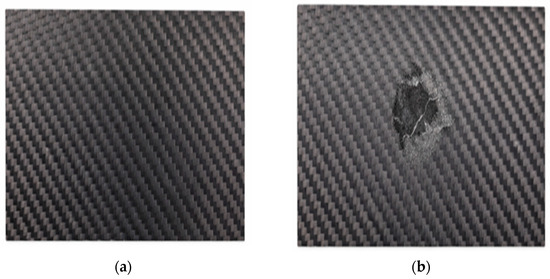
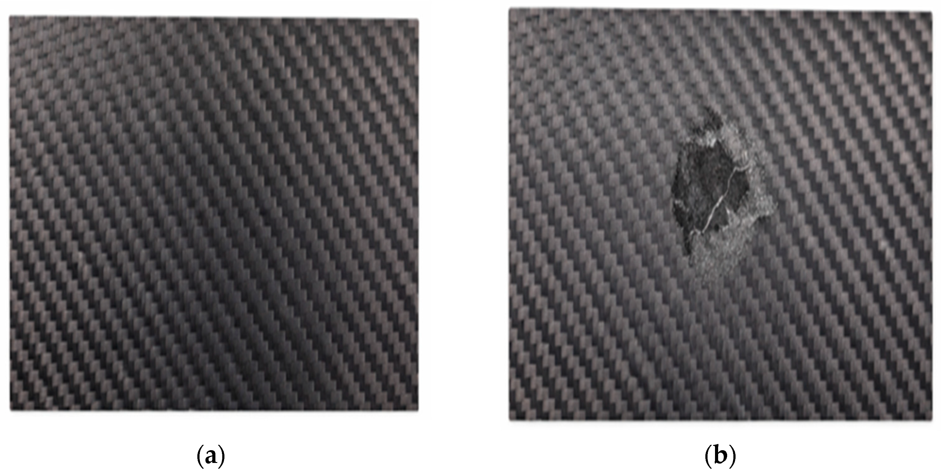
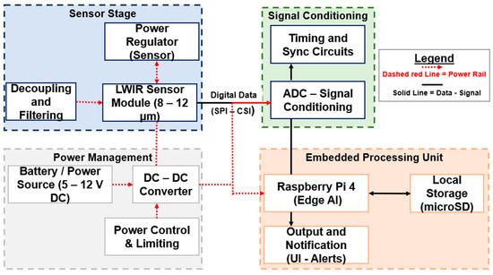
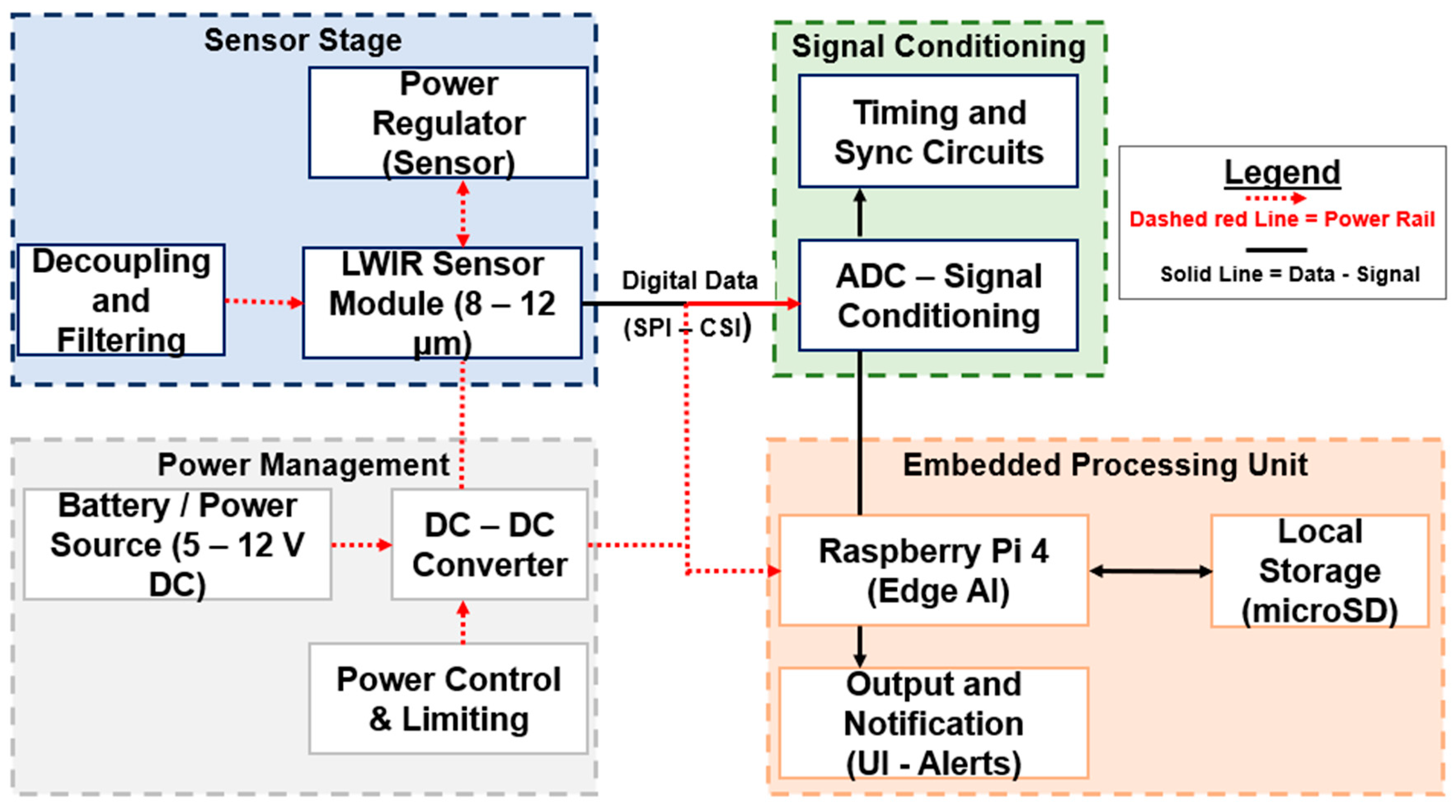
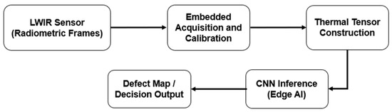
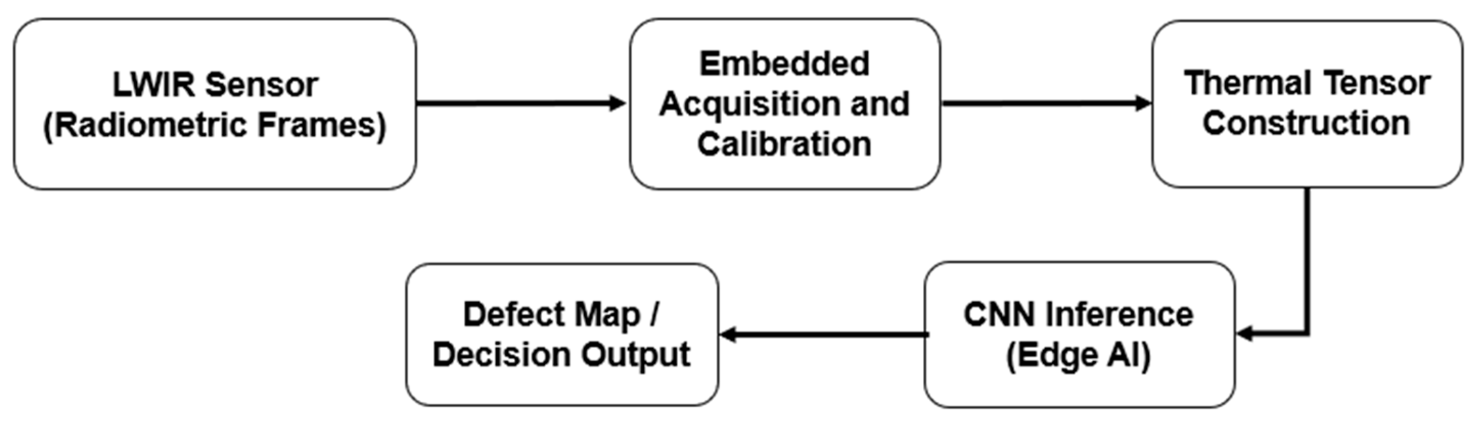
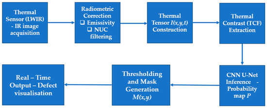
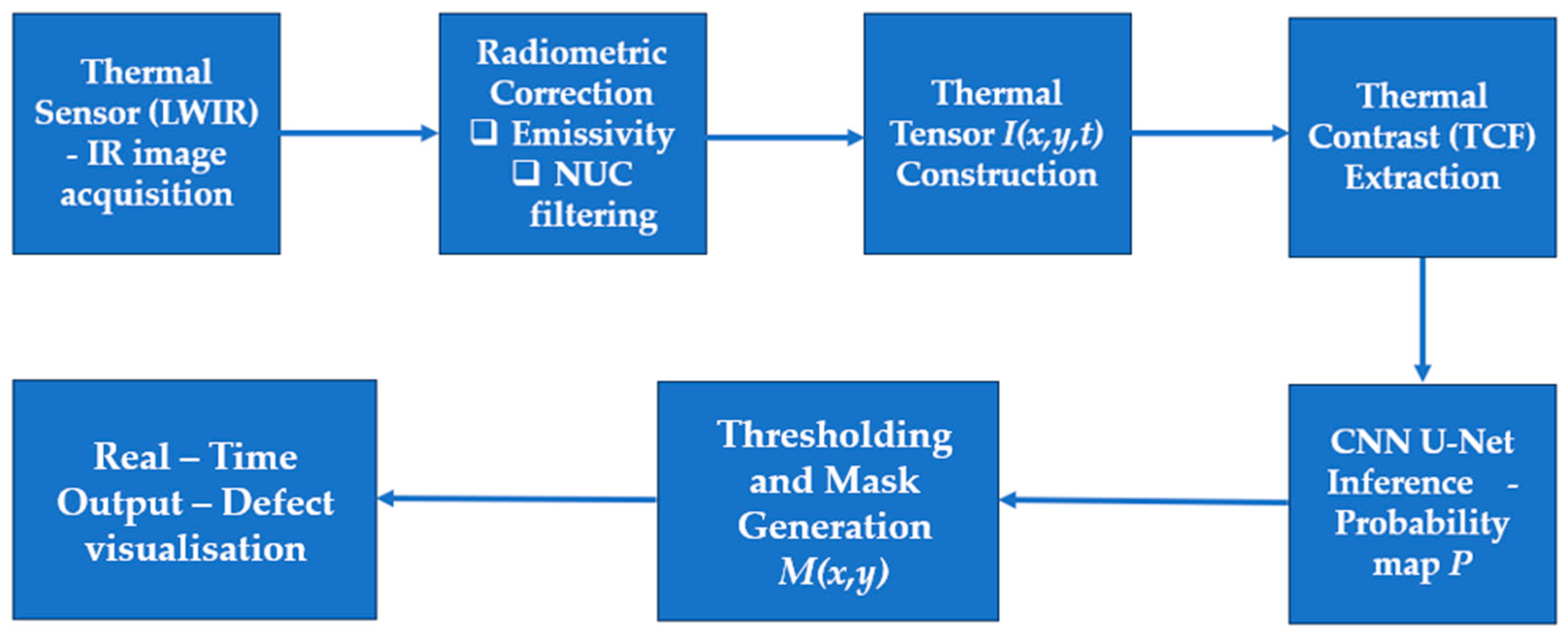
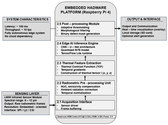
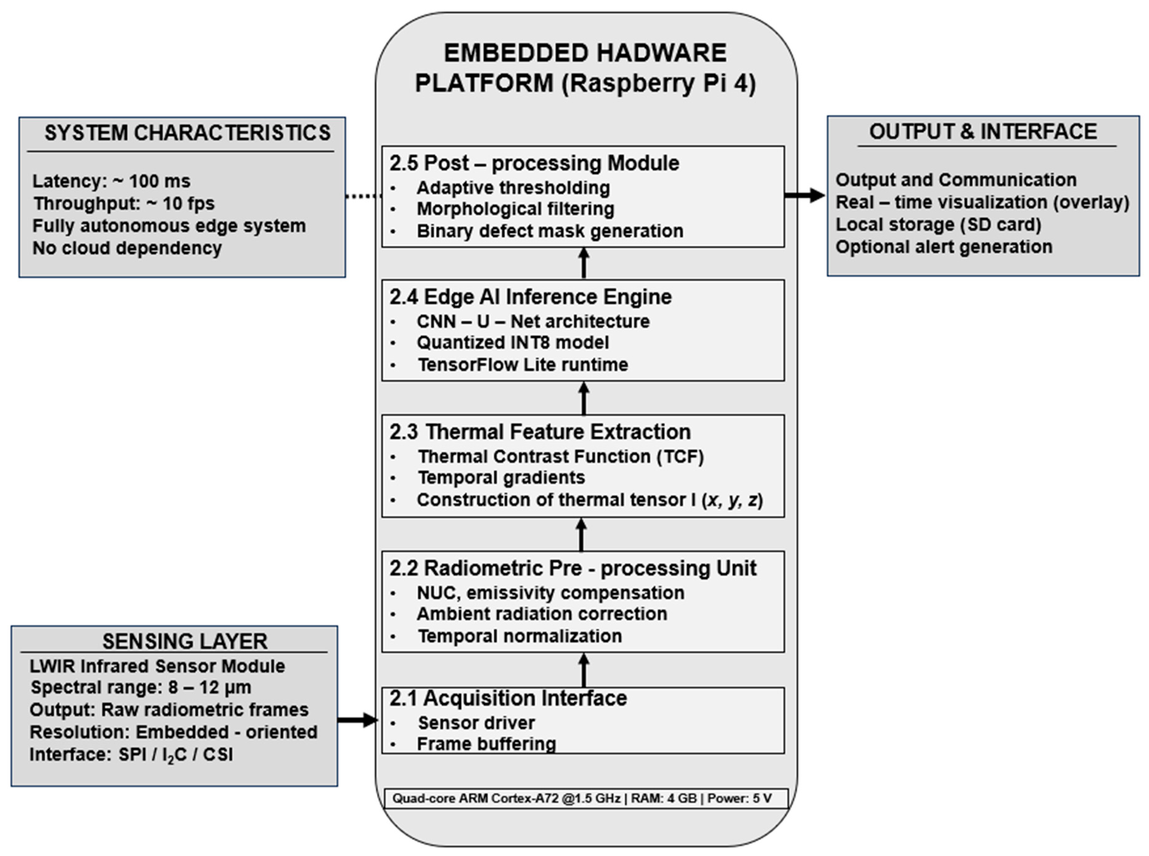
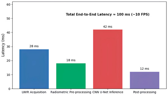
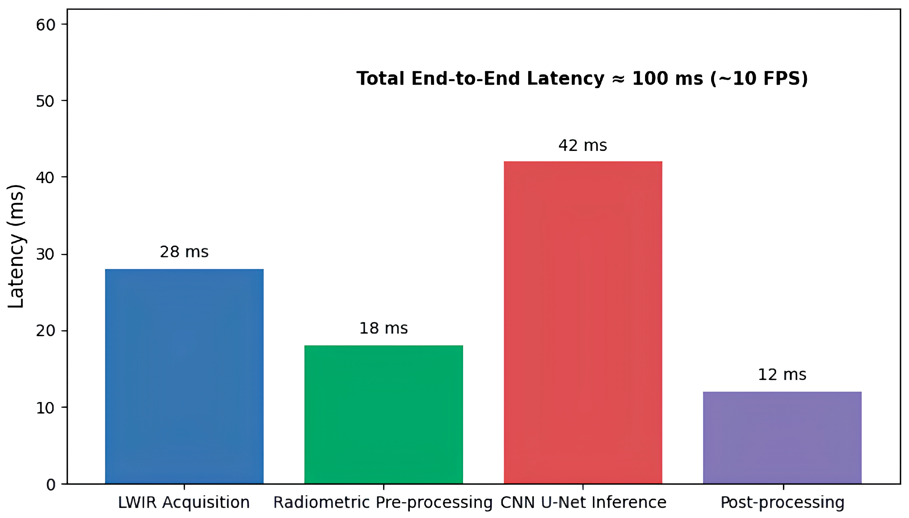
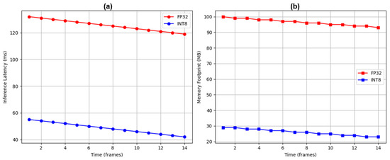
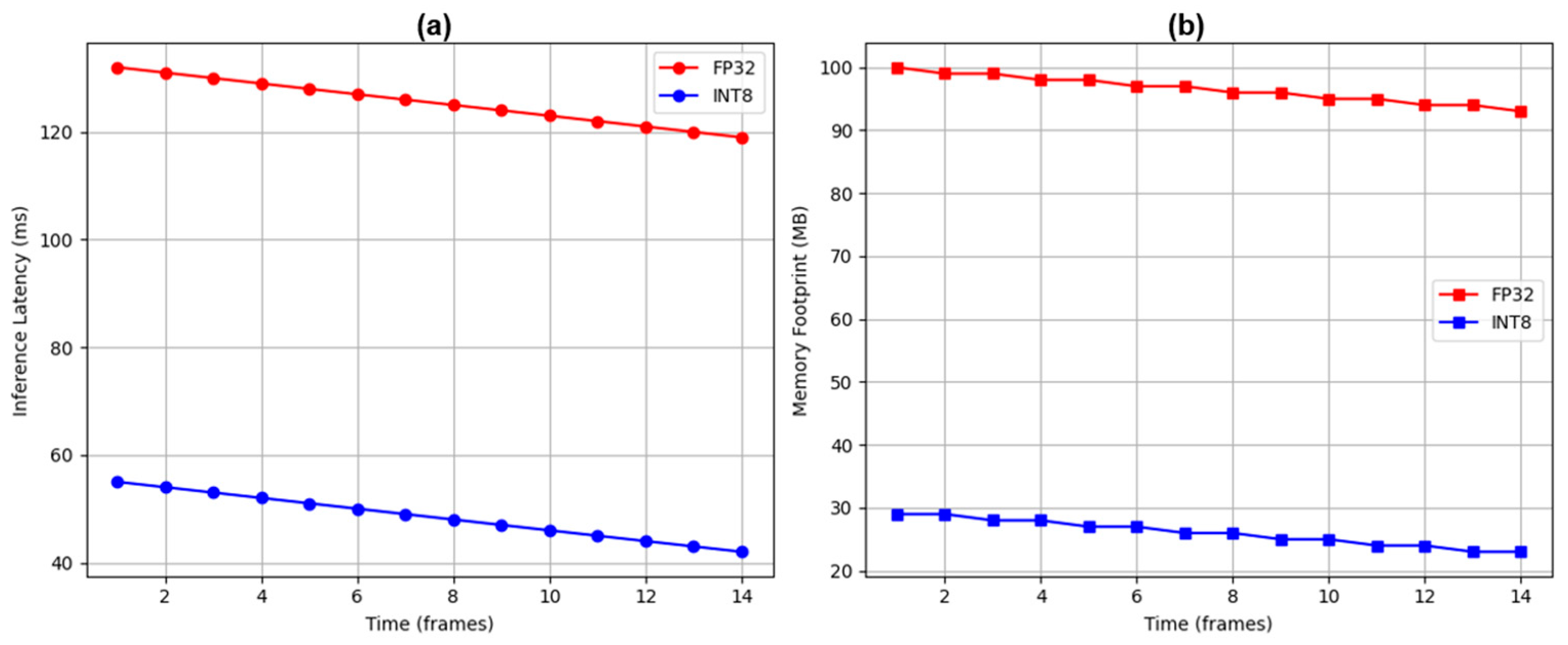
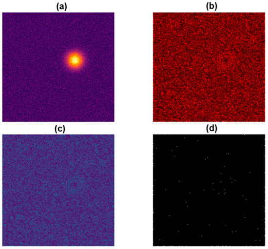
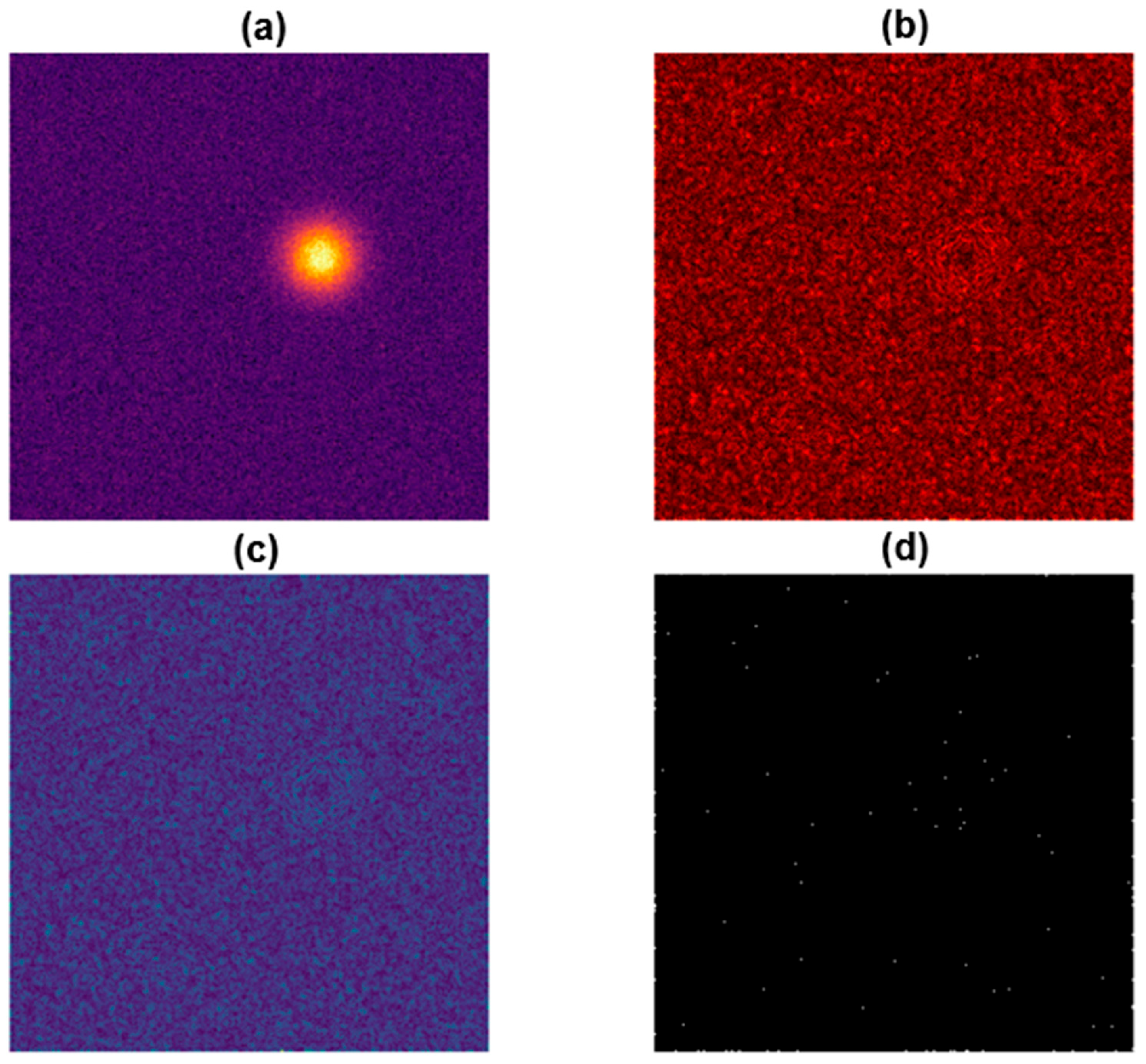
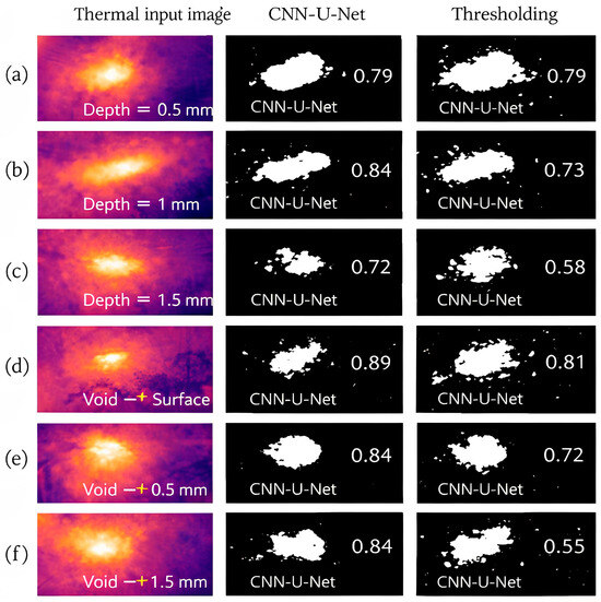
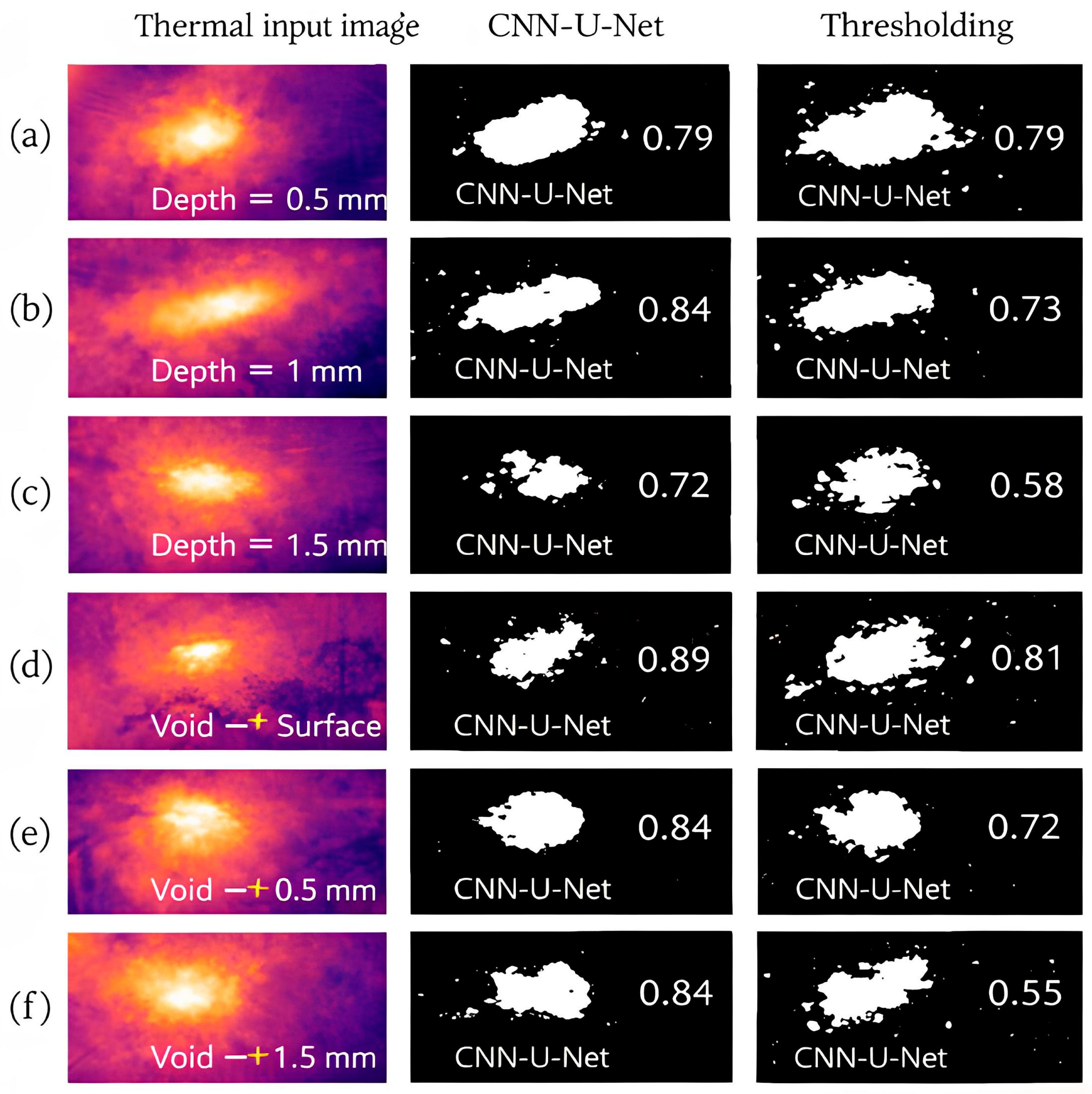
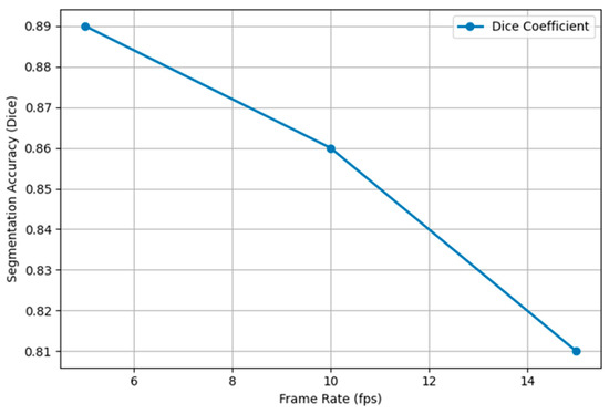
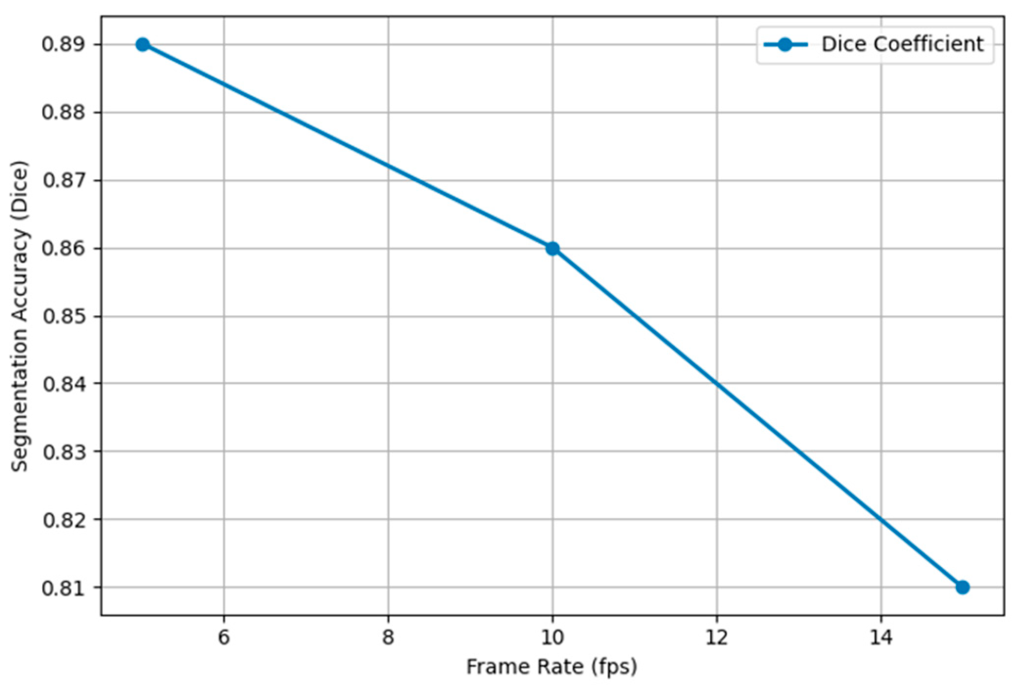

Disclaimer/Publisher’s Note: The statements, opinions and data contained in all publications are solely those of the individual author(s) and contributor(s) and not of MDPI and/or the editor(s). MDPI and/or the editor(s) disclaim responsibility for any injury to people or property resulting from any ideas, methods, instructions or products referred to in the content. |
© 2026 by the authors. Licensee MDPI, Basel, Switzerland. This article is an open access article distributed under the terms and conditions of the Creative Commons Attribution (CC BY) license.