


Abstract
This research significantly improves the link reliability and robustness of optical camera communications (OCC) by leveraging deep learning for light source modulation filtering, reflection filtering, and precise light source localisation. By using image sensors as receivers in OCC, data transmission is not only enabled, but other applications are also facilitated, such as detecting objects and humans, making OCC highly attractive in healthcare, intelligent transport systems, and indoor positioning. However, the position of the desired signal in the received image frame must be tracked in dynamic scenarios (i.e., nonstationary applications), in order to maintain the communication link. Moreover, as sixth-generation (6G) wireless networks envision highly autonomous systems that rely on seamless integration of communication and sensing, deep learning is key to enabling robust and adaptive light source localisation and sensing in OCC, which enables vision-based autonomy in dynamic environments. It should be noted that a deep learning-based approach provides more accuracy even when there are multiple noise sources in the environment, reflections, and complex backgrounds, and under mobility conditions, in which traditional light source detection/tracking methods are not effective. Hence this study investigates the use of a deep learning-based approach by analysing the detection accuracy under different configurations and unseen images. The results obtained demonstrate consistently high detection performance with average precision (at an intersection-over-union threshold of 0.70 of 0.84 to 0.97. These results pave the way for autonomous receivers that will be able to select signals intelligently and decode them.
1. Introduction
The number of Internet of Things (IoT) devices is expected to reach 40 billion by 2030 [1], which is driving the adoption of multiple wireless technologies in the sixth-generation (6G) wireless network and beyond to ensure high quality of services [2,3,4]. Notably, 6G envisions highly autonomous integrated sensing and communication (ISAC) systems. Moreover, for low-data-rate (i.e., less than 1 MHz) IoT applications, the visible light communication (VLC)–optical camera communications (OCC) technology, a subset of optical wireless communications (OWC), is seen as a viable candidate, since light-emitting diodes (LEDs) and cameras are available in many environments, thus freeing the radio frequency (RF) spectrum, allowing it to be used in areas most in need. In VLC-OCC, several light sources, including LEDs and liquid crystal displays, may be utilised as transmitters (Txs) [5], whereas image sensors (IS) or cameras in smartphones, traffic lights, vehicles, closed-circuit television, etc. can be used as receivers (Rxs).
Notably, 6G envisions highly autonomous and sensing integrated systems which align closely with the objectives of this work. OCC offers a number of interesting features, including object detection, vision, integrated sensing, positioning and communications, which are complementary to the VLC features. The major merit of the communication network in regard to sensing is that most of the infrastructure is already in place, with Rx/Tx nodes providing coverage, thus making sensing a relatively simple process.
The key light-IoT-based applications using camera-based Rxs include light infrastructure-to-device, vehicle-to-vehicle (V2V), vehicle-to-infrastructure [6], vehicle-to-road [7], vehicle-to-device (commonly referred to as vehicle-to-everything), and device-to-device communications. Currently, there is considerable interest in the internet of vehicles due to the inspiration that IoT provides [8]. Moreover, the ubiquitous increase in the widespread use of cameras such as dashcams, vehicle front- and rear-view cameras, speed cameras, security surveillance cameras, and traffic cameras and LED-based lights on roadsides, vehicles (e.g., headlights and taillights), traffic lights, etc., has opened up potential opportunities for the use of VLC-OCC in smart transportation systems to assist the traffic flow, reduce accidents, reduce energy usage (i.e., lower CO2 emission), and improve the quality of life.
Note that the global satellite-based navigation system, which is the conventional method for providing geographical information necessary for positioning and navigation applications, is ineffective when used indoors, underground (e.g., tunnels, subways) [9], and underwater [10]. VLC-OCC, therefore, could also be used in indoor environments (i.e., hospitals, shopping centres, underground, etc.) to provide localisation, where global positioning systems (GPS) are not available due to lack of RF signals.
Several studies have been conducted in OCC with the primary objective of increasing the data rate [11]. Many of these reported OCC works do not highlight light source localisation, with several assuming fixed LED positions/manual setting of the region of interest (ROI) [12,13,14,15], focusing more on demodulation rather than light source localisation. Some research works that have highlighted their light source detection/localisation method have utilised classical methods such as thresholding, region growing and blob detection [16,17,18], which are limited especially in cluttered scenes. In scenes with, e.g., reflections and unmodulated light sources, these classical techniques would have difficulty in identifying the real modulated light source as it does not have the capability to differentiate between real and unwanted light sources.
It is noteworthy that this work focuses on light source localisation and not directly on indoor positioning. Light source localisation here refers to identifying the ROI of the modulated light source in the image, which is a critical perquisite necessary for an OCC link to be established. In most OCC studies, the light source is manually selected in the image, which means that the system does not automatically determine the ROI as it is already informed manually. However, in real OCC deployment scenarios such as in autonomous robots and smart devices (for communications and positioning), the Rx must be able to automatically and reliably determine the pixels that correspond to the modulated light source in the image. Importantly, without correct light source localisation, communication cannot be established in OCC. Consequently, this work focuses on automatic light source localisation in cluttered environments, a challenge that is yet to be adequately addressed.
Few works have used deep learning to determine the LED’s ROI in the captured image frames prior to decoding [19,20,21,22], but their method is aimed and designed for a specific LED and controlled environment, rather than a generalised light source localisation technique that can operate in cluttered or heterogenous environments with, e.g., background noise, dynamic environments and un-modulated light sources. For example, in [23] convolutional neural networks (CNN) for detecting ROI due to taillights for symbol recognition in OCC-based V2V communication links were reported. However, these links are constrained to specific applications with a single taillight type/LED array. Similarly, the ROI recognition approaches in [17,19,20,22,23] are task-specific, focusing on symbol or colour classification or proximity-based OCC (i.e., identifying the closest LED Tx). These works do not consider general, environment-agnostic LED localisation in cluttered scenes containing non-modulated light sources, such as those found in indoor IoT or mixed-lighting environments. In [24,25,26], deep learning has been used for signal demodulation/classification, but not for light source localisation. However, deep learning techniques, particularly CNNs, that recognise patterns in images can be used for accurate light source localisation. Importantly, one of their most irresistible features is that CNNs have the capacity to robustly learn spatial or temporal features in images [27,28].
To enable accurate light source localisation in an image, our contributions in this paper are to
- Develop a modulation- and reflection-aware object detection model using deep learning for LED-based localisation in VLC-OCC for dynamic and cluttered environments.
- Design and evaluation of multiple light source localisation beyond arrays/taillights.
- Demonstrate experimentally the potential of OCC Rxs that are autonomous.
Although this work focuses on establishing a reliable baseline method for autonomous light source localisation in OCC, it is noteworthy to recognise the continuous advancement in artificial intelligence (AI). Ongoing improvements in AI-based approaches will therefore remain essential for enhancing the accuracy and robustness of autonomous OCC Rx systems. Emerging techniques such as the adaptive fused domain-cycling variational generative adversarial network (AFDVGAN), multimodal techniques for arc detection in railway systems, and dynamic collaborative adversarial domain adaptation network (DCADAN) have the potential to further advance the deployment of autonomous OCC Rx. AFDVGAN is designed to mitigate data scarcity problems and generate high-quality synthetic data [29]. This approach can significantly expand the range of training datasets, thereby enhancing the robustness of the resulting outputs. DCADAN supports adaptation to environments that differ from the original training domain [30], while multimodal arc-detection techniques used in railway systems [31,32] offer valuable insights for integrating multiple sensing capabilities for OCC systems. Together, these advances can enhance detection accuracy, reliability, and overall system robustness.
2. Background
2.1. OCC Fundamentals
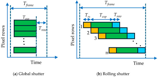
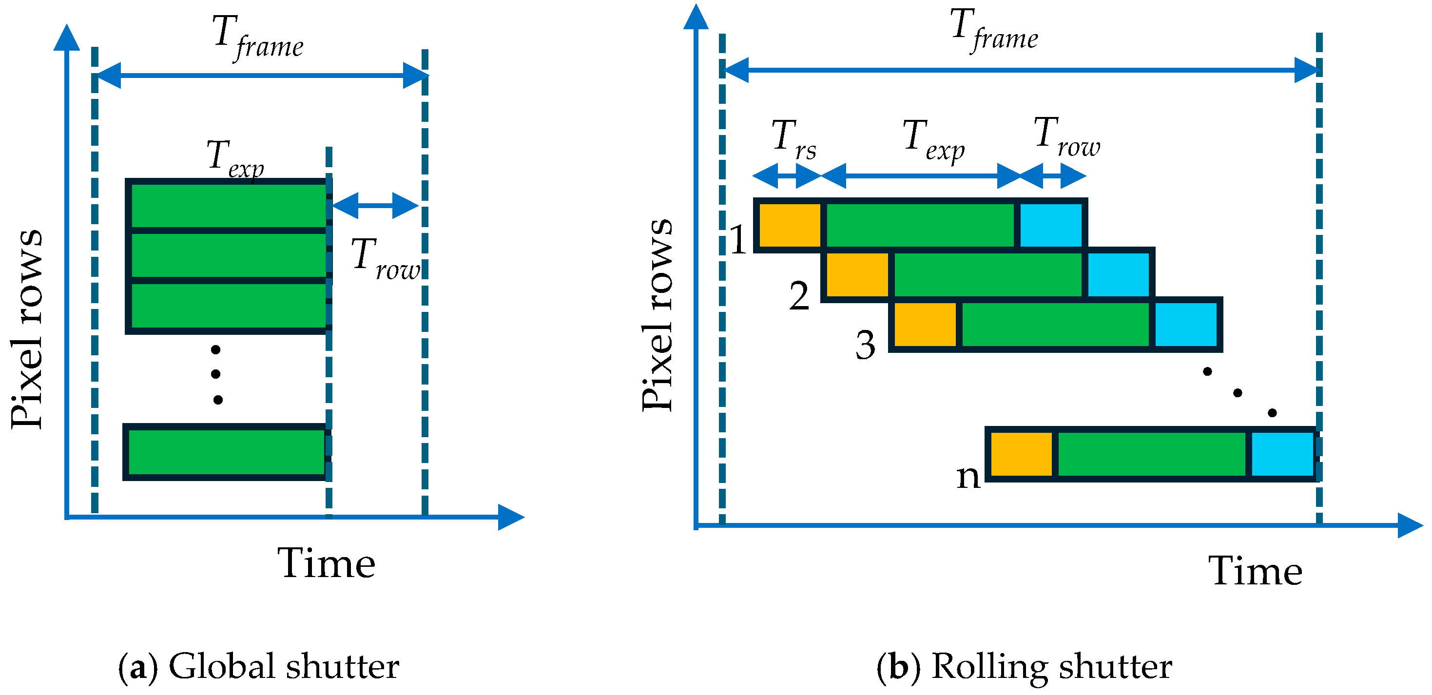
In OCC, ISs (e.g., smartphone cameras, dash cameras, and traffic cameras) and light-emitting diodes (LEDs), and screen displays are used as the Rxs and Txs, respectively, which are intended for low-data-rate applications such as IoT. In OCC, an IS (i.e., camera) captures the intensity-modulated (IM) light sources in the form of image sequences for further processing to recover the data. There are two types of capturing modes, the global shutter (GS) and the rolling shutter (RS). In the former, all pixels of the IS are exposed all at once, while in the latter, each pixel row is exposed in a row-by-row sequential manner with fixed row-shift (or a reset time) and read-out times of Trs and Trow, respectively; see Figure 1. In the RS mode, there are distinct strips or rows illuminated with the captured light source at high frequencies and a relatively short exposure time Texp, indicating the signal’s status. For a two-level intensity illumination pattern, there will be ‘on’ and ‘off’ states, i.e., bright and dark strips/bands.
Figure 1.
Global and rolling shutter capturing.
A major advantage of RS-based cameras is that the achievable data rate Rd is greater than the camera frame rate Rf [33] compared to GS-based ISs where Rd ≤ Rf. Note that in cameras, the brightness of an image is primarily influenced by three parameters: (i) the shutter speed, also referred to as the exposure time; (ii) ISO or gain, which refers to the sensitivity of the sensor to the light, which depends on the camera type; and (iii) the aperture, which regulates the amount of light entering through the camera’s lens system into the IS.
2.2. Unique Features of OCC
Camera-based Rxs have some unique advantages over photodetector (PD)-based Rxs: (i) when used with array LEDs, each camera pixel can detect signals of different colours (i.e., red, green, and blue), enabling massive multiple-input multiple-output capabilities; (ii) they feature an adaptive wide field of view (FOV) that can capture multiple IM light sources transmitted over line of sight, non-line of sight, or a combination of both. However, OCC typically offers lower Rd than high-speed PD-based Rxs (commonly used in VLC), primarily due to the limited frame rates of most state-of-the-art off-the-shelf cameras. Nonetheless, this lower Rd should not be viewed as a limitation since it remains sufficient for many applications, including vehicular communications [34,35,36], indoor IoT [37], localisation [38,39], advertising [40], sensor networks [41], motion capture [42,43], and many others.
2.3. Object Detection Architectures
In general, there are broadly two major object detection architectures: one-stage and two-stage detectors. There are, however, few other architectures or hybrid schemes that do not exactly fit into these two categories. Faster-region CNN, mask-region CNN and fast-region CNN are two-stage detectors that exhibit high precision by utilising deep feature extraction and dedicated object proposal mechanisms [44]. They follow a two-stage approach, i.e., region proposal (first stage) followed by detection/classification (second stage). The first stage identifies regions where an object might be found in the image, while the second stage involves classifying the objects in each region [45]. However, the sequential processing pipeline of two-stage detectors, while robust and offering high precision, incurs higher computational costs, rendering them less suitable for time-critical applications [44]. Conversely, one-stage detectors such as single-shot detectors and the You Only Look Once (YOLO) family series integrate region generation, feature extraction, and classification into a unified model, significantly increasing inference and enhancing usefulness for real-time applications, though sometimes at the cost of accuracy in tasks requiring fine-grained localisation [44].
3. Light Source Localisation Problem and Proposed Methodology
3.1. Light Source Localisation Problem
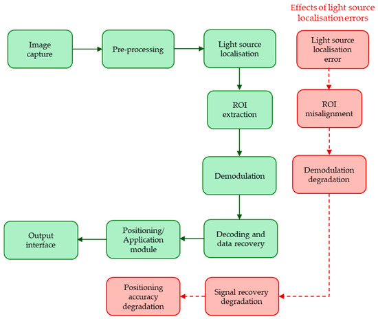
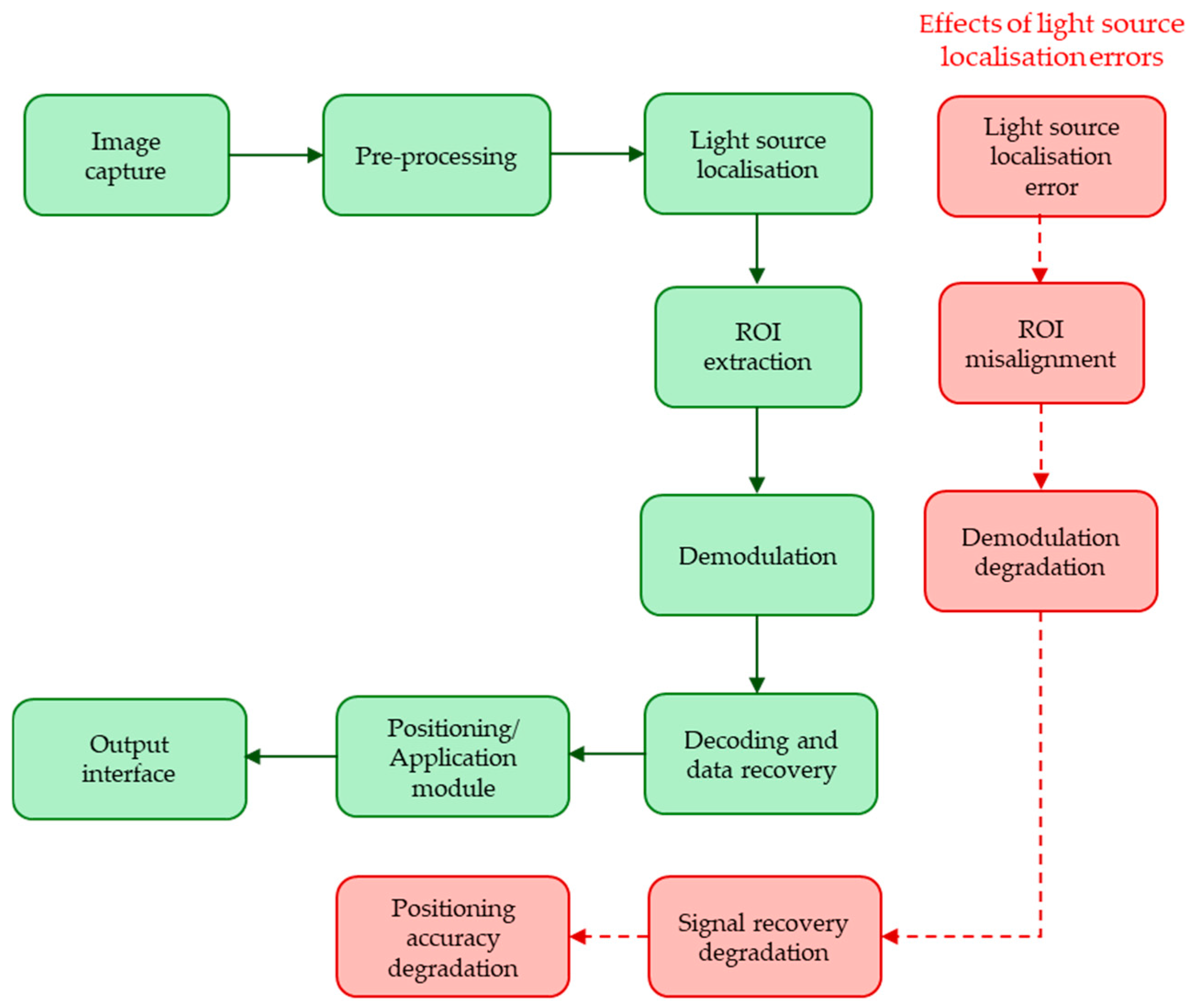
Light source localisation involves the accurate detection of a light source in an image frame. Light source localisation is image-domain ROI identification, while positioning involves physical coordinate estimation using a decoded light source ID and geometry. Importantly, the OCC reception pipeline involves image capturing of the intensity-modulated light source and light source localisation, which involves identifying the location of the modulated light source within the captured image. Moreover, accurate light source localisation is also key because a camera’s FOV typically includes not only the desired light source but also other objects and scenes. Also, multiple light sources (modulated and unmodulated ones) could have been captured, as well as reflections. The next stage following light source localisation is the ROI extraction, i.e., extracting the pixel coordinates of the identified light source in the captured image. Thereafter, demodulation, decoding and recovery of the transmitted data stream occur, followed by positioning. Importantly, errors encountered at the light source-based localisation stage propagate to subsequent stages. This is because inaccurate ROI (i.e., ROI misalignment) leads to inaccurate pixels, hence leading to degraded demodulation and signal recovery, consequently leading to degraded positioning accuracy. Figure 2 provides a system-level block diagram of the proposed OCC reception pipeline and error propagation. As this paper focuses on the correct ROI pixels reaching later stages, full demodulation or positioning error propagation modelling is out of the scope of this work.
Figure 2.
OCC reception pipeline and error propagation.
Classical LED detection techniques such as thresholding and blob detection assume the LED to be a solid uniform bright region against a darker background. This is the case in some OCC systems; however, for RS-based capture, an instensity modulated LED does not appear as a solid uniform bright region but as strips of bright and dark bands representing the on and off states of the LED. Also, these classical methods, even under non-RS captures, would struggle in accuracy where there are unwanted light sources such as unmodulated ones and reflected light sources in the captured image frame.
3.2. Proposed Deep Learning-Based Light Source Localisation
The proposed deep learning approach in this work uses the YOLOX anchor-free object detector for training, which is an improved variant within the YOLO family. The model is trained to distinguish between modulated light sources, reflected modulated lights and unmodulated lights and outputs the bounding boxes of the desired detected light source and its coordinates.
The YOLOX model is a high-performance, one-stage, anchor-free object detector [46]. It incorporates recent advancements such as decoupled head, anchor-free design and an improved label assignment strategy. These enhancements enable it to achieve a more balanced trade-off between speed and accuracy compared to earlier YOLO versions across all model sizes [46]. It finds the location of objects by identifying their centres instead of depending on memory-intensive predefined anchor boxes [47]. Also, the anchor-free mechanism in YOLOX considerably cuts down the number of parameters that usually demand heuristic turnings [46], which makes the training simpler and less prone to errors, compared to other one-stage but anchor-based methods such as single-shot multibox detector, RetinaNet and EfficientDet.
3.3. Dataset Preparation
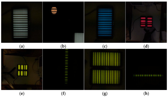
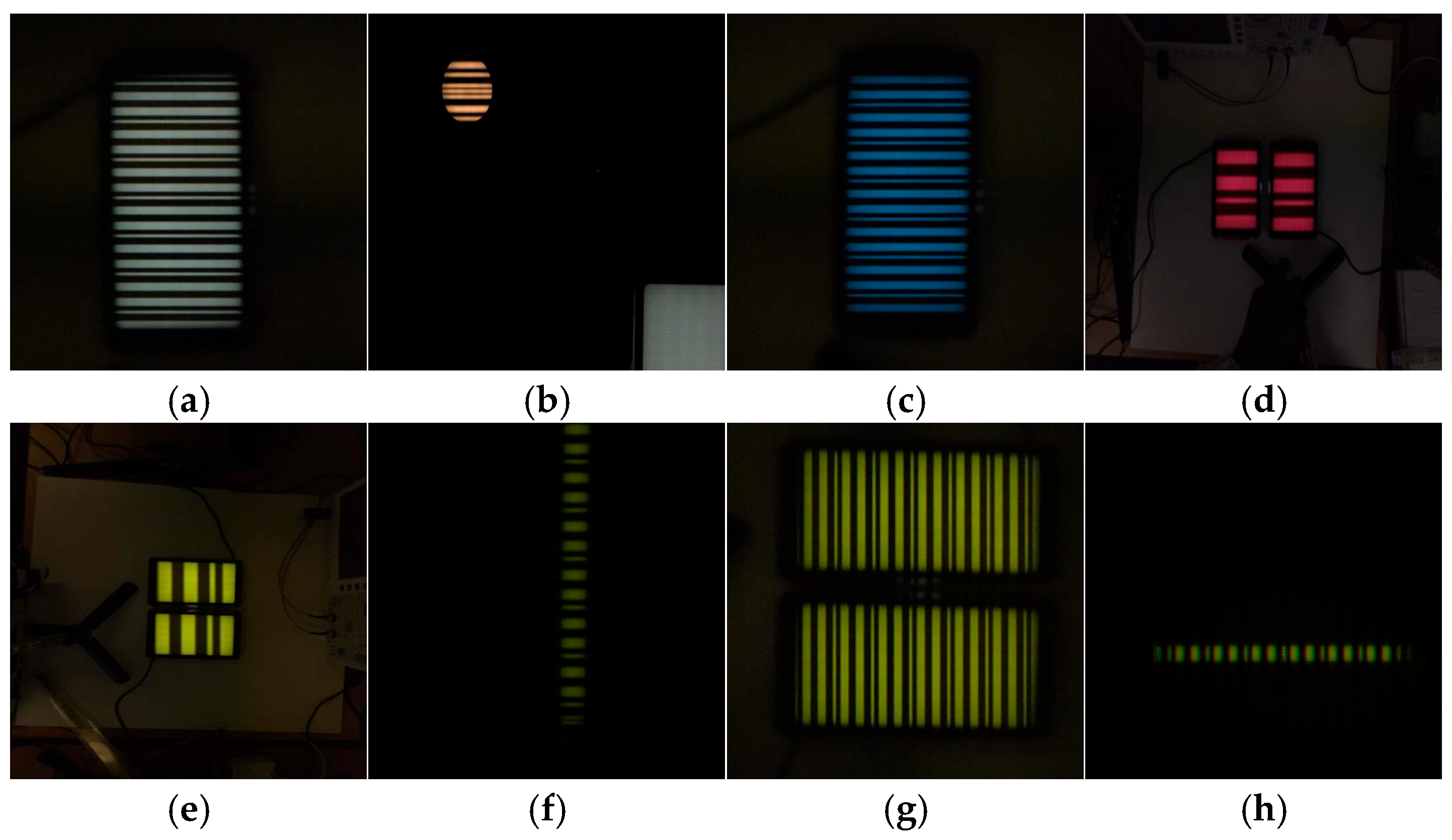
Images of modulated LEDs were captured at ~20 and 50 cm and at specific ISOs (80, 160, 200 and 1800) and a shutter speed of 1/12,000 s. The LEDs were circular and rectangular in shape. Different LED light colours were also captured such as blue, red, green, and white. The training and validation dataset comprises approximately 160 labelled images captured under controlled experimental conditions, covering diverse conditions including different LED types, distances, modulation states, reflections and background lighting. The light sources in the captured images were annotated using bounding boxes.
Horizontal flip augmentation was incorporated into the training, providing additional diverse samples from the original dataset. To test the robustness of the system, at least 10 unseen images per test category were used that contained, e.g., multiple LEDs under ambient and artificial lighting, LEDs positioned at different distances from the camera than those used for training, varied ISO settings, and captures taken at different angles (i.e., tilts). Some of the images contained additional objects such as a desk, wires, a measuring ruler, device stands, cartons, paper, a noticeboard and laboratory devices including power supply and signal generator units. Since images are captured at low exposure times, these objects are generally not prominent in the presented samples. Some images also contained unmodulated light sources which were incorporated to train the system to accurately distinguish between modulated and unmodulated light sources. Overall, the dataset represents a cluttered laboratory environment.
The captured modulated LEDs used for training were labelled using MATLAB R2024a image labeller application. YOLOX was used for training. Different learning rates and batch sizes were used. Figure 3 shows examples of image datasets used for general training and those used as unseen test images for a different modulated LED colour (yellow) which was not in the training set.
Figure 3.
Dataset samples for training (a–d) and for a different unseen modulated LED colour test category (e–h).
3.4. Training
The training pipeline was implemented in MATLAB, leveraging the deep learning toolbox, computer vision toolbox and image processing toolbox. Transfer learning is a popular technique that transfers knowledge learned from a large dataset to a smaller dataset to improve performance on limited data. It enhances results on small datasets by initialising the model with weights learned from a large dataset [48]. Consequently, transfer learning was incorporated using the Tiny Common Objects in Context (COCO) pretrained backbone, which is suitable for lightweight models, and fast training was used with the YOLOX object detector. The COCO dataset released by Microsoft includes over 330,000 annotated images covering about 80 object categories, where many images contain multiple objects and have become a benchmark dataset for object detection [48].
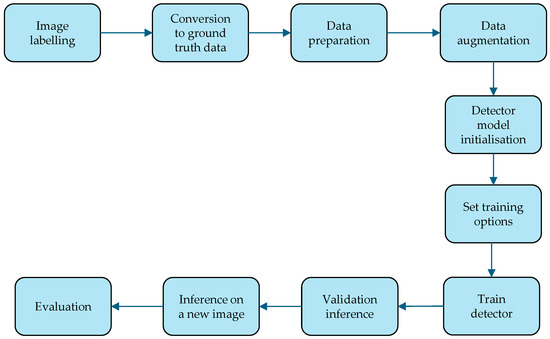
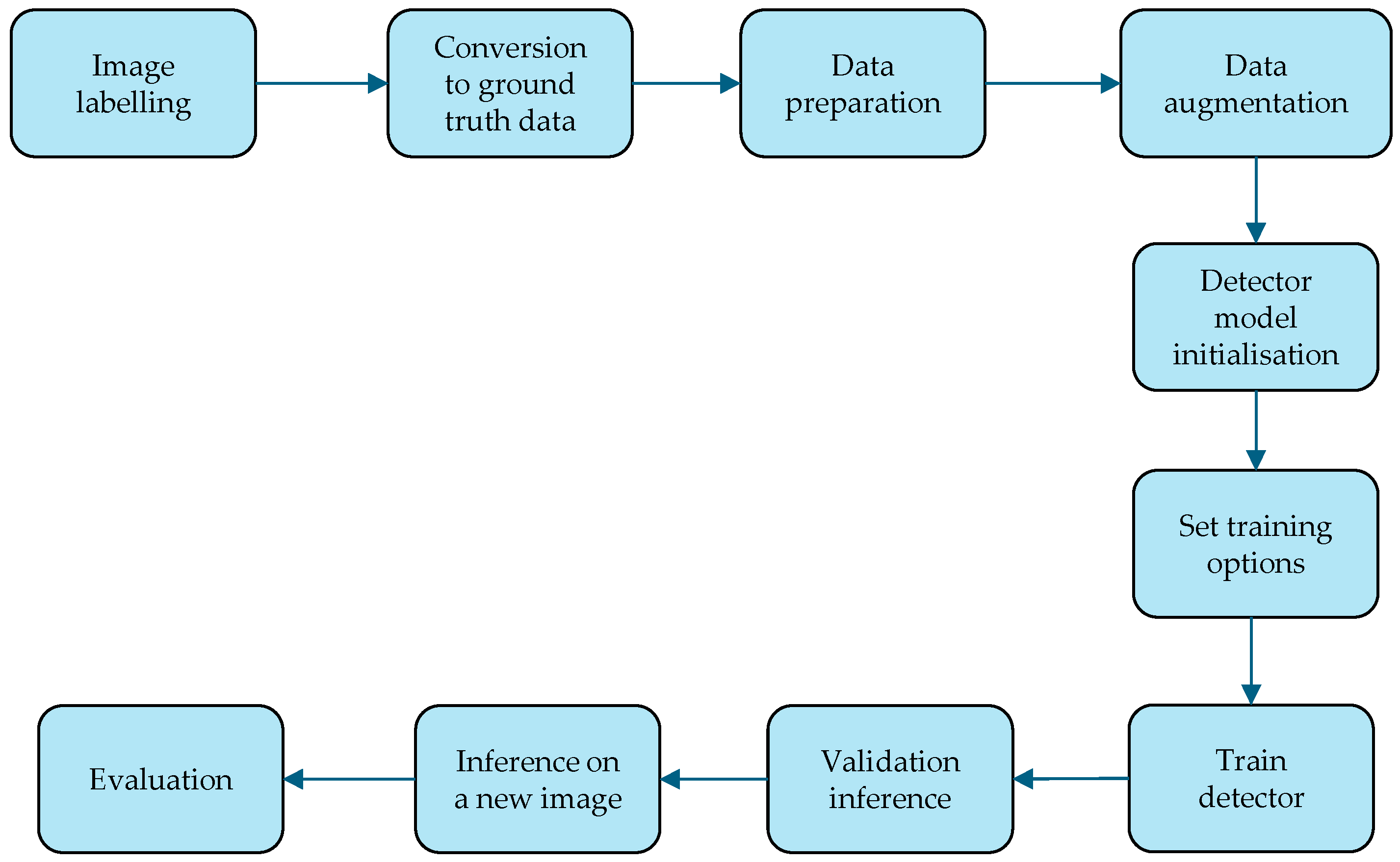
Figure 4 shows the flow diagram of the training and inference pipeline for the modulated LED detection. Ground truth data were prepared and stored. Eighty percent of the dataset was used for training and twenty percent for validation. The datasets were randomly shuffled during training (shuffling after every epoch) to improve the generalisation of the model, mitigating it from memorising sample orders and hence allowing the learning of more robust features, leading to better detection accuracy. A horizontal flip augmentation was applied to increase the robustness of the model. The training parameters are shown in Table 1, and the deep learning detector was trained using the prepared training dataset and validated using the validation dataset. The robustness of the trained model is tested using unseen new images, and the system performance is evaluated using different performance evaluation metrics, as highlighted in Section 4.
Figure 4.
Flow diagram of training and inference pipeline.
Table 1.
Key training parameters.
3.5. Key Engineering Implementation Factors
In future real-world deployments, several key engineering implementation factors will be critical, including computational power, energy consumption, and annotation costs. Autonomous OCC Rx can operate using either on-device AI inference or cloud-based processing. While cloud-based systems offer greater computational power, they introduce higher latency due to server/network-dependent processing and may be less reliable because they rely on stable connectivity. In contrast, on-device AI provides more consistent performance by processing data locally but requires careful system optimisation to align with device hardware capabilities [49]. Strategies for model compression have been introduced to improve energy efficiency [50]. Designing lightweight models that preserve performance is another promising research direction, as it reduces system complexity and improves computational efficiency [49,51]. These considerations are especially important for devices with limited computational resources (i.e., power); improved efficiency directly enhances overall performance and reduces energy usage [49]. In terms of data annotation, labelling large-scale datasets remains both time-consuming and costly. Deep active learning techniques have been proposed to reduce annotation costs, as well as semi-supervised labelling strategies that further minimise the need for manual labelling [52].
4. Experimental Setup
4.1. Testbed
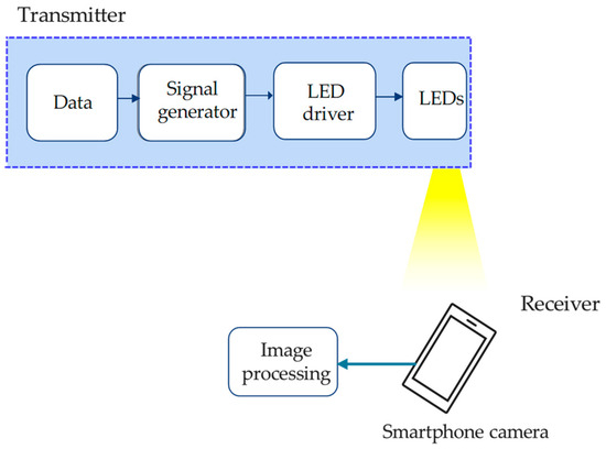
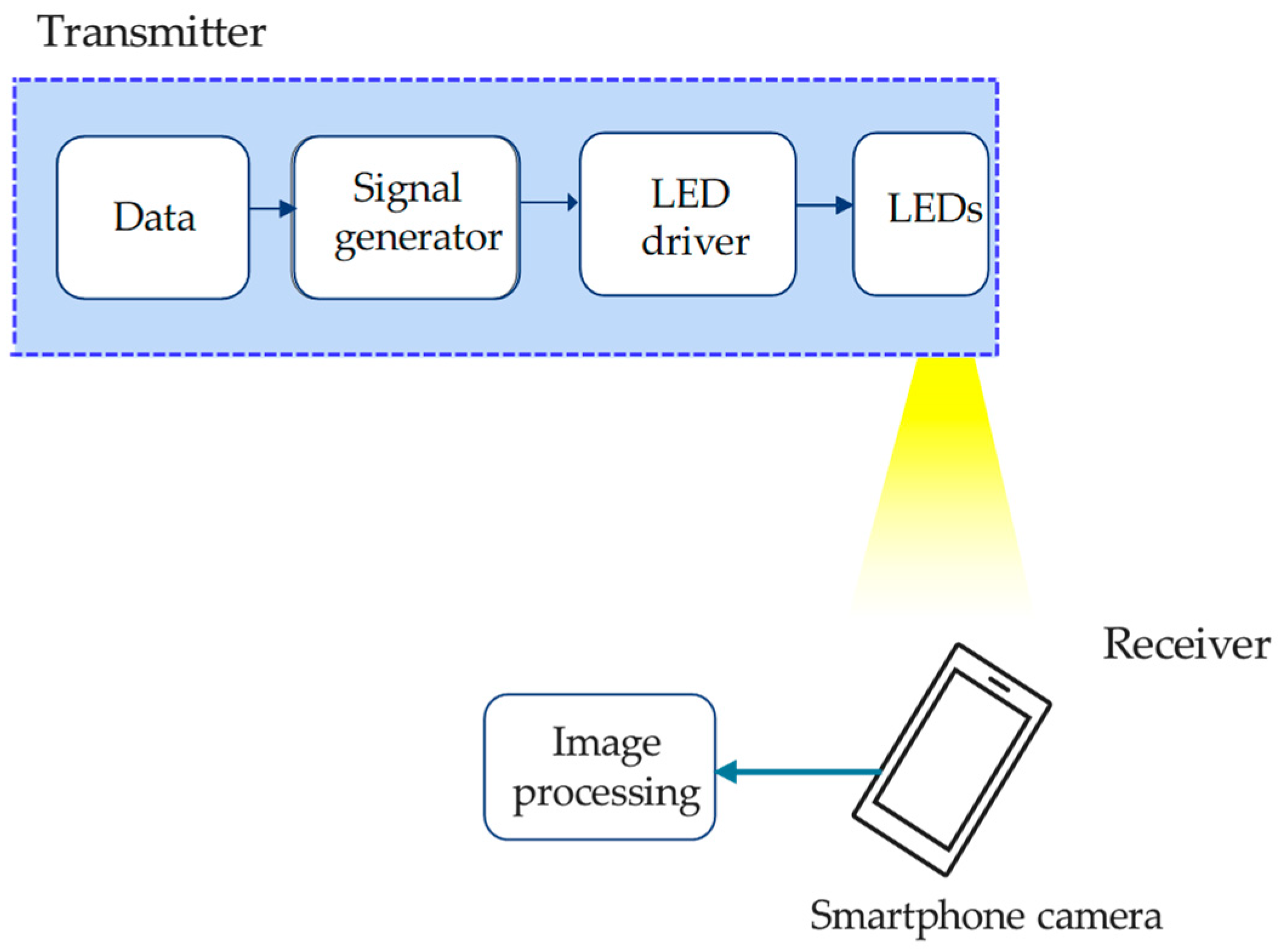
The testbed comprises an LED driver, LEDs, arbitrary waveform generators (Multicom Pro MP750290, Singapore and Keysight 33500B, Colorado Springs, CO, USA), power supplies (TTi EL302D Dual power, Cambridgeshire, UK) and an RS IS (Samsung Galaxy S25 smartphone rear camera, Seoul, Republic of Korea). The LED driver with the arbitrary waveform generator is used to modulate the LED. Binary intensity modulation format is employed. The experiment is carried out in an indoor environment under daylight conditions. Image capturing was done under varying ambient lighting conditions. The experimental schematic block diagram is shown in Figure 5.
Figure 5.
Schematic block diagram of experimental set-up.
4.2. Evaluation Scenarios
We test a variety of scenarios to evaluate the robustness of our proposed technique, such as (i) different LED and camera distances; (ii) multiple light sources that are modulated; (iii) multiple light sources including non-modulated artificial lights; (iv) different background scenes; (v) different ambient light levels; and (vi) different camera capture parameters such as shutter speed and ISO. Results are presented in Section 5.
4.3. Evaluation Metrics
To determine the detection accuracy of the proposed deep learning light source detection and localisation, we use performance metrics such as average precision, F1 score, precision and recall. The average inference time per frame is also provided.
- Precision: Precision Pr is the ratio of true positives tp to the sum of true positives and false positives fp [53]. It indicates the proportion of correctly identified positive instances out of all the items that the model predicted as positives. It indicates how accurate the positive predictions are. In the context of this work, the precision metric indicates the reliability of the detections (i.e., the detected light sources). It represents the proportion of correctly detected light sources relative to all predictions. False positives may result in incorrect ROI detection and, consequently, incorrect signal decoding. Mathematically,
- Mean raw precision (MRP): This refers to the arithmetic mean of the precision values. Notably, this is different from average precision which involves the area under the precision–recall curve.
- Recall: Recall Re is the ratio of true positives to the sum of true positives and false negatives fn [53]. It measures how accurately the model identifies positive instances, showing the proportion of actual positive cases that the model correctly detects. Mathematically,
In the context of this work, the recall metric is key, as it reflects the model’s ability to correctly identify the required light sources present in the captured image. Achieving a high recall value ensures that none of the required light sources are overlooked.
- Average precision (AP): This is the area under the precision–recall curve. It measures how well a model balances precision with recall [54]. This can be expressed aswhere is as a function of .
- F1 score: This is the harmonic mean of precision and recall [54]. This metric balances precision and recall into a single metric. This can be described as
- Intersection-over-Union (IoU): This represents the ratio of the overlap between the ground truth and the predicted region to their combined area [54]. If Gbx and Pbx denote bounding boxes for the ground truth and predicted region respectively, then is the area of intersection and is the area of union (combined area); hence
5. Results and Discussion
5.1. Unseen Test Conditions
In this section we evaluate the robustness of the trained detector to unseen conditions. We categorise these into four main test categories: unseen colour, different LED type, modulation awareness and reflection awareness. Several other conditions were introduced into unseen image test sets that intentionally differ from the training data. Table 2 summarises these differing conditions which include the unseen modulation frequencies, LED colour, different distances, tilt angles and different reflection capture angles.
Table 2.
Training (seen) and test (unseen) conditions.
The test categories that are utilised are explained below:
- Unseen colour: The training additionally incorporated green, blue and red LEDs. Yellow LEDs were intentionally unused for training but used for testing.
- Modulation awareness: Unseen images with different modulation frequencies to the training, different tilt angles and distances and with reflection were utilised for the test. This combines multiple varied conditions different from the trained dataset.
- Reflection awareness: Images for this category were captured at a different tilt angle/distances from the dataset used for training.
- Different LED type: Two different LED types and shapes absent in the training were utilised. This is to assess how well the detector can detect different LEDs which do not appear in its training set. Additionally, for the tested unseen images, we also introduced ISOs different from those in the training images.
Each test category highlighted above was tested independently using the same trained detector to allow comparability.
5.2. Detection Performance
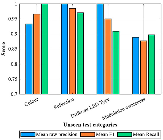
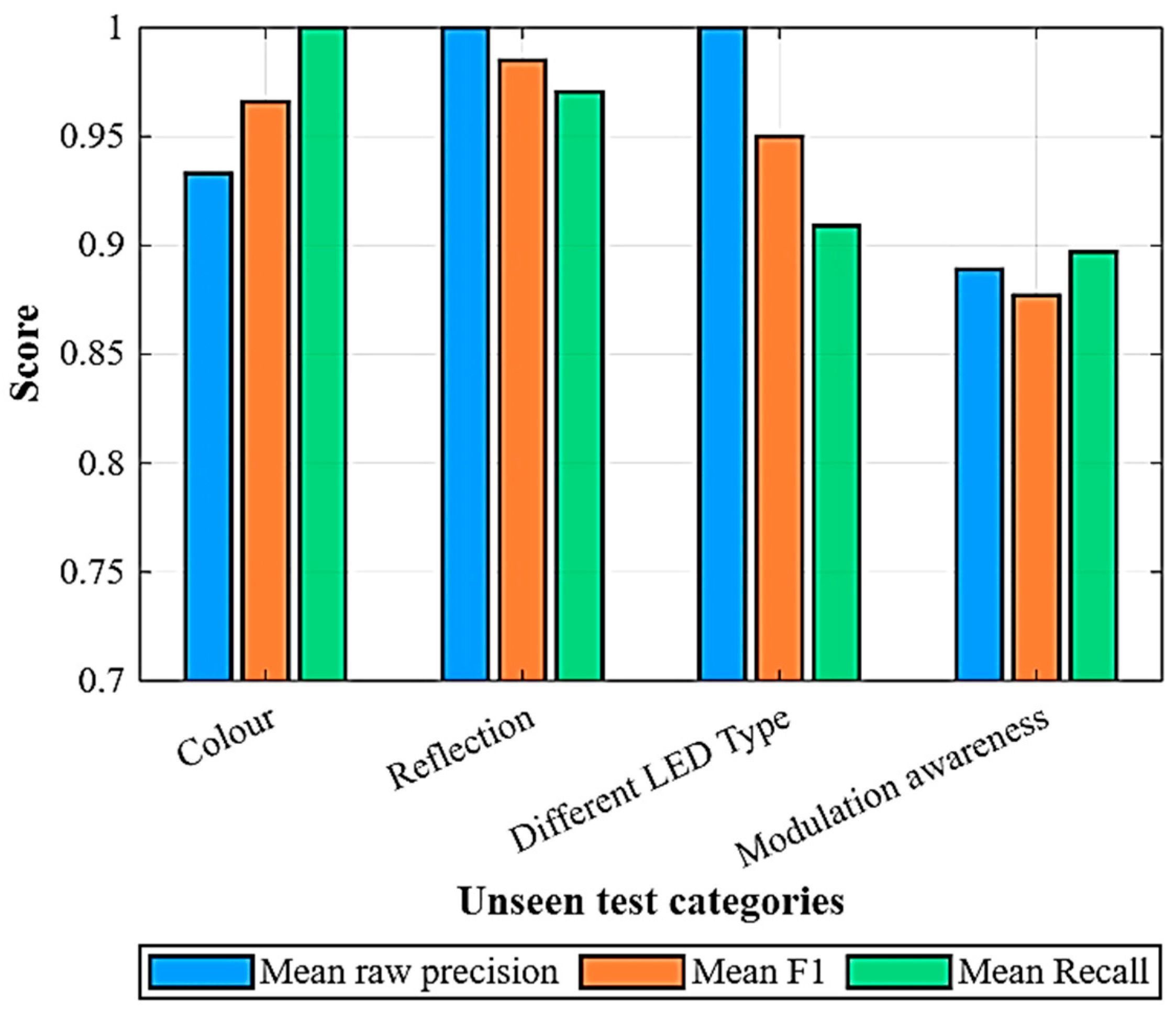
Table 3 and Figure 6 show the quantitative performance across the different test categories. The proposed system maintains a high accuracy across different unseen setups. As shown in Table 3, we obtain a high AP (at IoU of 0.70) of 0.84–0.97; the best F1 scores are above 0.95, with mean raw precision of 0.89–1.00 despite significant differences in the unseen tested images and the training set. These results show that the model generalises effectively to modulation frequency changes, unseen LED type and colour, and different LED and reflection capture geometries. Furthermore, the average inference time of 0.070–0.075 s per frame shows real-time applicability.
Table 3.
Summary of performance across test categories with unseen images.
Figure 6.
Comparison of model robustness for test categories.
5.3. Precision–Recall Analysis
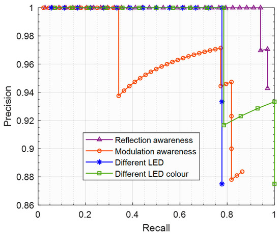
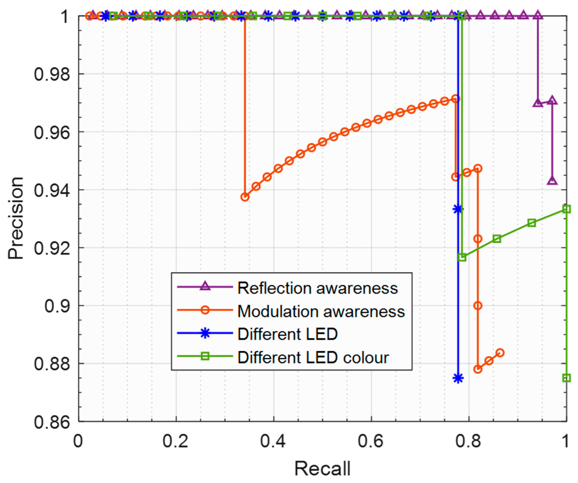
Precision–recall curves demonstrate the trade-offs that exist between precision and recall. A good precision–recall curve has a high area under the curve, indicating both high precision and high recall. Figure 7 shows the precision–recall curve at an IoU threshold of 0.70 for each test category. The curves remain close to the top right position which shows a low false-positive rate and consistent recall. The relatively smoother consistency of the precision–recall curve for the unseen colour and reflection awareness suggests more stable confidence scores and minimal wrong classifications despite spectral and geometric variations from the training set. It is typical to have recall values less than 1 in object detection.
Figure 7.
Precision–recall across test categories.
For a recall value of 1 to be achieved, the detector must detect all the ground truth objects without missing any. In practical systems, this may not always be the case; hence, recall values would be close to 1 but <1, showing strong detection. It is noteworthy that the modulation-awareness category combines various test scenarios beyond modulation awareness alone, including reflections and images captured at different tilt angles and distances from those in the training dataset (as highlighted in Section 5.1). Consequently, multiple sources of variation are introduced, resulting in a slightly lower recall compared to the reflection-aware and different LED colour categories. Additionally, since the model was trained using only three modulated LED types, training with a broader range of modulated LEDs would further improve its performance in detecting different LED types.
5.4. Qualitative Results
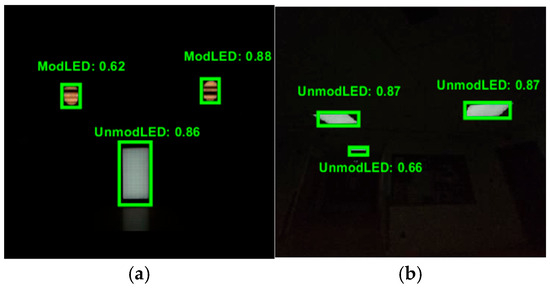
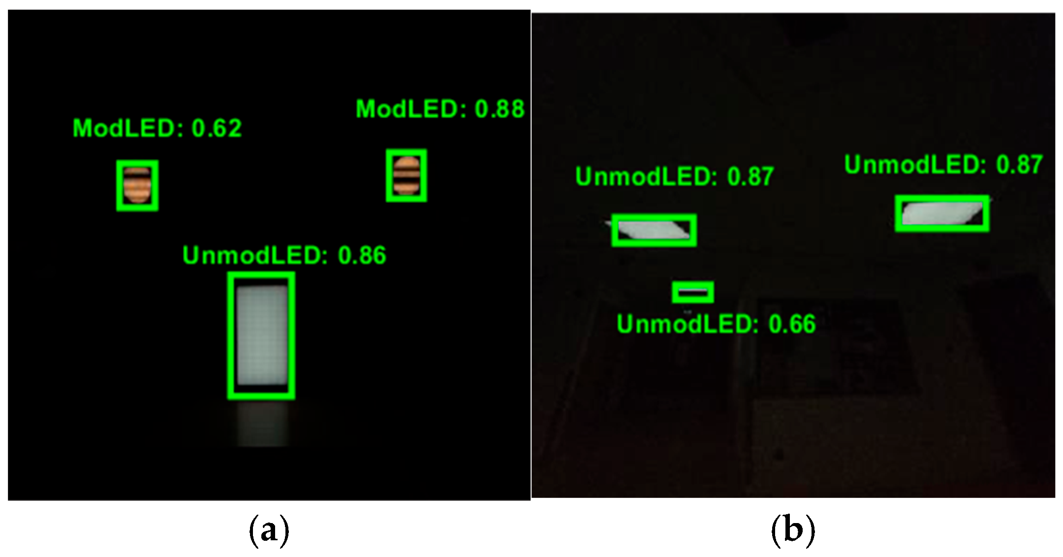
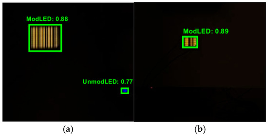
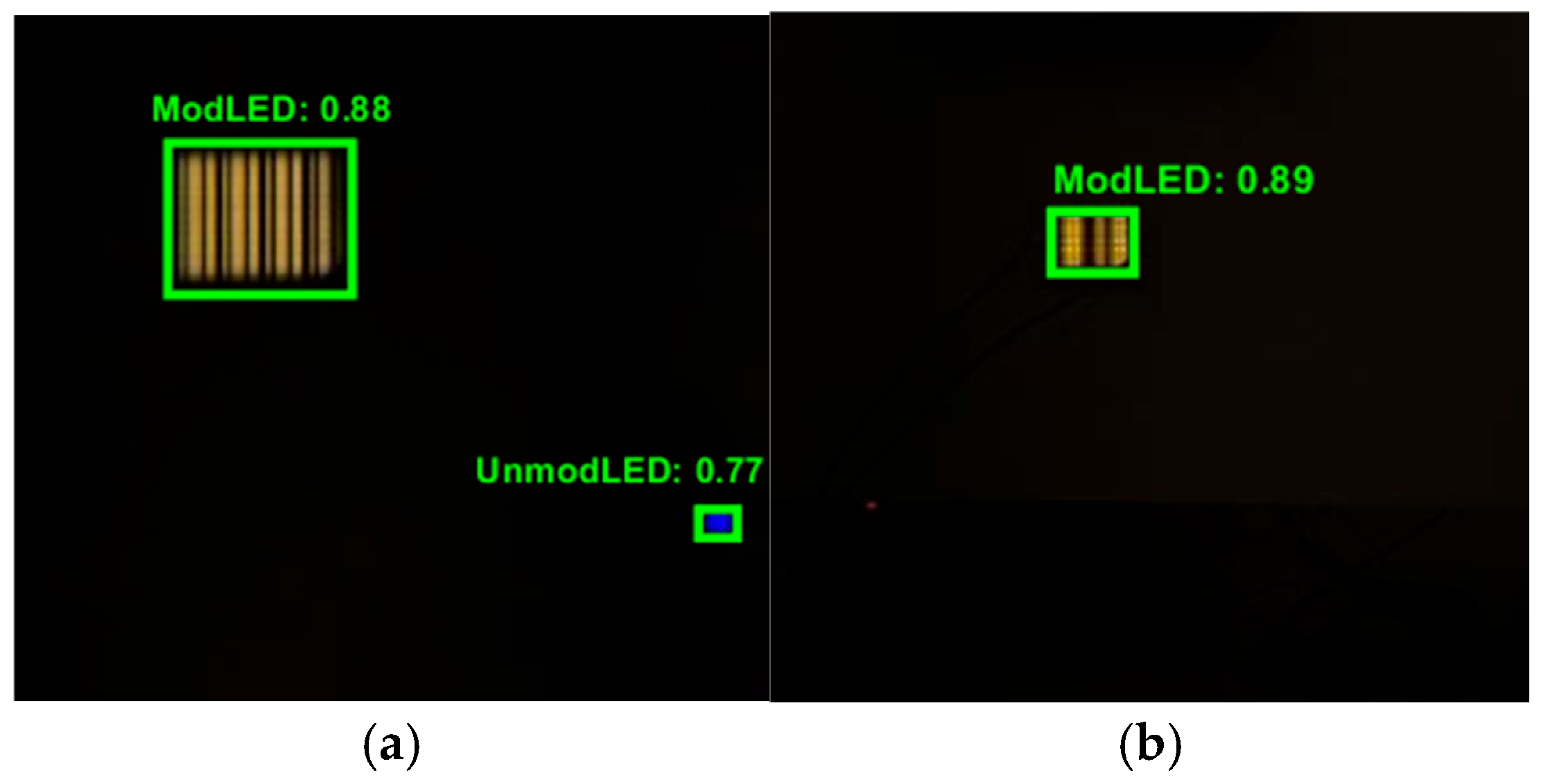
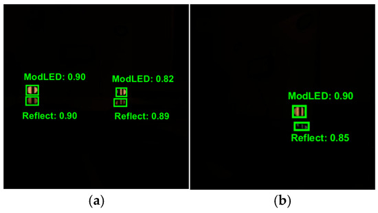
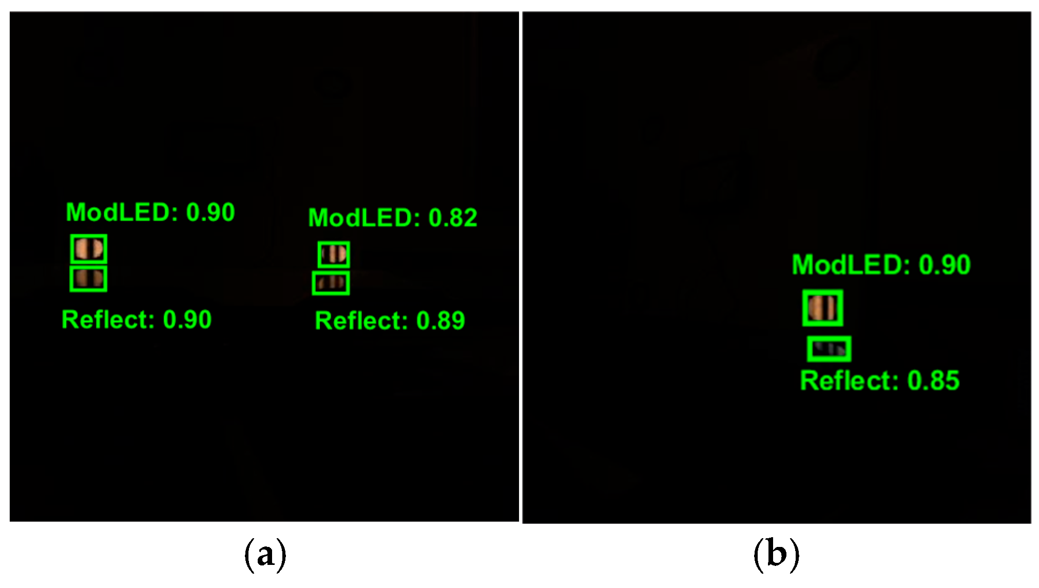
Figure 8, Figure 9, Figure 10 and Figure 11 show qualitative samples of detection outputs for each test category. The output bounding boxes accurately localise the modulated light sources (represented as ModLED by the modulation and reflection-aware light source localisation detection system developed), unmodulated light source (represented as UnmodLED), and reflected modulated light sources (represented as Reflect) with a good confidence level even under different unseen test conditions. These shows that the model provides reliable spatial localisation. Notably, the values shown near the bounding boxes represent the detection confidence scores, also referred to as probability score, which indicates how likely it is that the detected object belongs to a specific category or class [55]. Confidence scores generally range from 0 to 1, with 1 being the maximum.
Figure 8.
Examples of detection outputs for the modulation-aware detection category; (a) modulated (ModLED) and unmodulated light (UnmodLED) sources detected; and (b) multiple unmodulated light sources detected (UnmodLED).
Figure 9.
Examples of detection outputs with different LED types that did not appear in the training set; (a) a modulated (ModLED) and unmodulated light (UnmodLED) source detected; and (b) a modulated light source detected (ModLED).
Figure 10.
Examples of detection outputs with reflection-aware detection: (a) two modulated light sources detected (ModLED) and their reflected copy (Reflect) and (b) a modulated light source detected (ModLED) and its reflected copy (Reflect).
Figure 11.
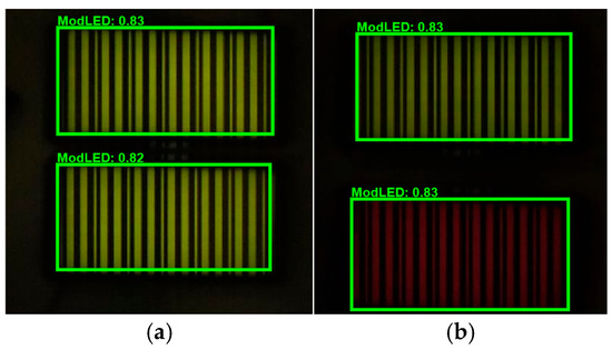
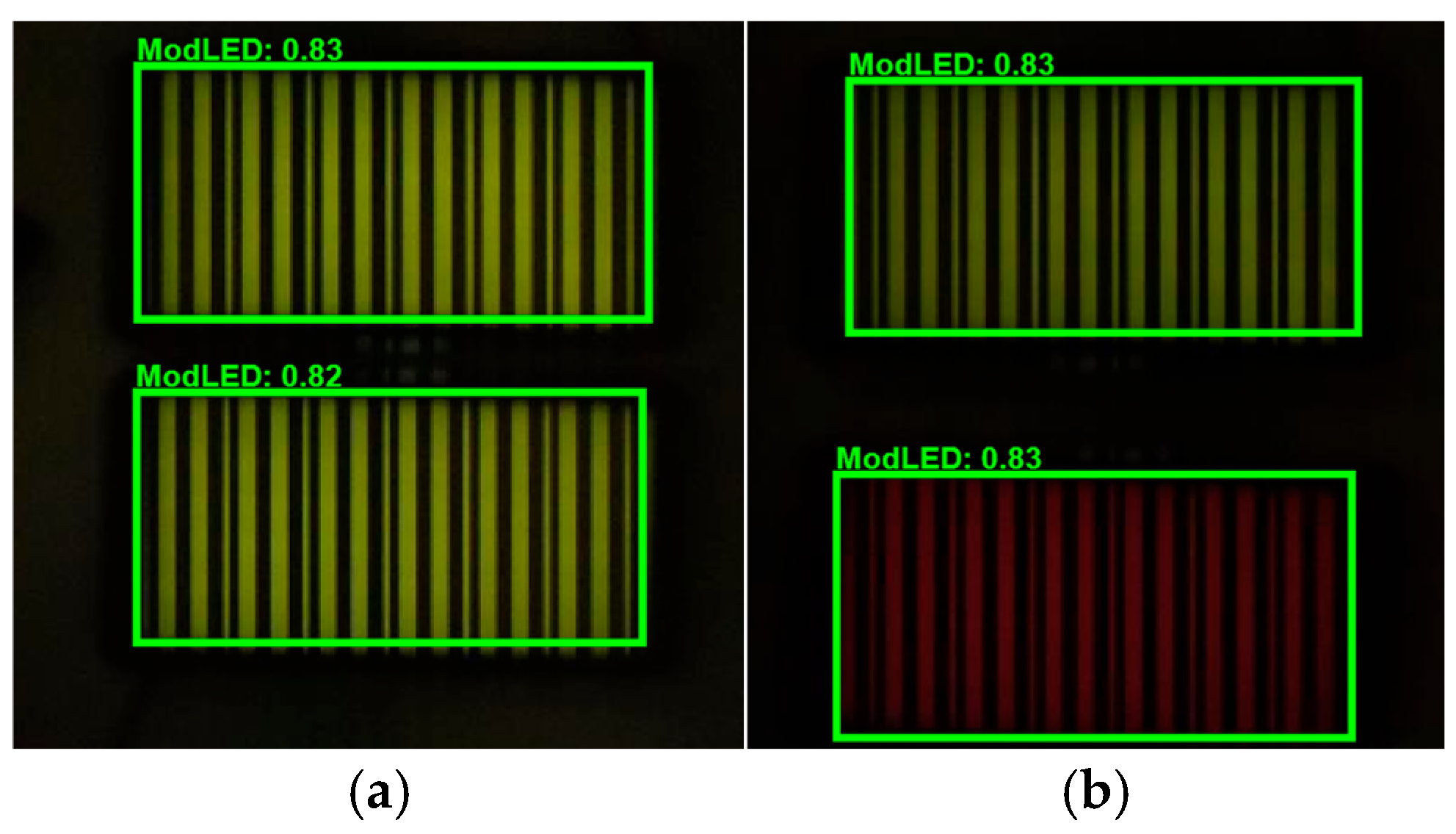
Examples of detection outputs with a different light source colour (yellow) that did not appear in the training set: (a) two modulated yellow light sources detected (ModLED); (b) a yellow modulated light source detected alongside a red light source (ModLED).
5.4.1. Modulation-Aware Outputs
As shown in Figure 8, the system automatically detects whether a light source is modulated or unmodulated, allowing the correct localisation of a communication/positioning-based modulated light source.
5.4.2. Different LED Type Output
Figure 9 shows some examples of the output of detected light sources for the test category involving LEDs different from those the system was trained with. The examples of results shown here in Figure 9 demonstrate that the system can generalise to unseen LED types and still correctly identify different types of LEDs and determine their modulation status.
5.4.3. Reflection-Aware Outputs
Reflective surfaces can create a reflected copy of a light source, which would be captured by the OCC Rx if the reflected copy is within its FOV. In this case, it is advantageous to be able to differentiate the actual light source from its reflected copy. Further benefits of reflection-aware detection are discussed in Section 5.5. Figure 10 shows the output of our reflection-aware OCC detection system where the real modulated light source (ModLED) and its reflected copy (Reflect) are correctly distinguished.
5.4.4. A Different LED Colour Detection
Beyond other features of the developed autonomous OCC detection system, this system can also detect LEDs of different colours beyond what it was trained with, as shown in Figure 11. A yellow modulated LED was not used in the training but the system still generalises to this unseen colour type and accurately identifies the LED.
5.5. Benefits of the Proposed Autonomous OCC Detection System
5.5.1. Reflection-Aware Detection
Positioning information provides location-based data, allowing accurate navigation. OCC positioning is especially suitable for indoor scenarios where GPS fails. For OCC positioning, one of the ways to determine one’s location or that of an asset (asset tracking) is via the reception and decoding of an LED identification (ID) in the location using a camera. The received LED ID can then be used to correctly determine the location of an individual or an asset with high positioning accuracy. Particularly, in manufacturing plants, OCC indoor positioning can be utilised for robotics or asset tracking which requires cm/sub cm positioning accuracy. However, with the capture of the reflected light source copy, errors would be introduced into the system as the system would not be able to distinguish between the actual light source and its reflected copy; hence, the accuracy of the actual LED coordinates in the captured image would be compromised, making the need for reflection-aware detection necessary.
5.5.2. Selective Detection
With deep learning-based light source recognition, the OCC reception system can be trained to detect and exclude certain types of light source, allowing selective detection and filtering. This can provide several benefits and applications which are yet to be discovered or harnessed in OCC, which include increased security levels where the OCC Rx can filter out suspected intruding LED captures, as well as adaptive region of interest determination allowing both line-of-sight and non-line-of-sight modulation-aware detection.
6. Conclusions
This paper presented an autonomous OCC receiving system to address the challenge of robust light source localisation/detection in OCC. Light source localisation, which involves identifying the ROI of the modulated light source in the image, represents a critical perquisite necessary for an OCC link to be established and maintained. We investigated the use of a deep learning-based approach. We evaluated this approach across different test categories such as unseen LED type, unseen LED colour, and modulation and reflection awareness conditions different from those in the training set. The results obtained for the four test categories evaluated showed robustness to unseen conditions. Particularly, the results showed high AP (@ 0.70 of 0.84–0.97), mean raw precision (0.89–1.00), and F1 scores (best scores F1 scores 0.95–1.00), demonstrating a strong capacity to generalise to unseen conditions. This proposed method provides reliable modulation and reflection filtering, enabling more robust autonomous light source localisation required in real-world OCC systems. Future research could explore the incorporation of physical reflection modelling to further improve accuracy in reflection-based awareness scenarios.
Author Contributions
Conceptualization, E.E., S.S. and F.B.O.; methodology, E.E., S.S., F.B.O., X.L. and S.R.; software, E.E.; validation, E.E.; formal analysis, E.E.; investigation, E.E.; resources, S.S. and F.B.O.; data curation, E.E.; writing—original draft preparation, E.E.; writing—review and editing, E.E., S.S., F.B.O., X.L., L.Y., S.R. and Z.G.; visualisation, E.E.; supervision, S.S.; project administration, S.S.; funding acquisition, S.S., F.B.O., X.L., S.R. and Z.G. All authors have read and agreed to the published version of the manuscript.
Funding
This work was supported by the Future Telecoms Research Hub, Platform for Driving Ultimate Connectivity (TITAN), sponsored by the Department for Science, Innovation and Technology (DSIT) and the Engineering and Physical Sciences Research Council (EPSRC) under grant numbers EP/Y037243/1 (TITAN TMF) and EP/X04047X/2 (original TITAN Grant).
Data Availability Statement
The original data presented in the study are openly available in Zenodo at https://doi.org/10.5281/zenodo.18234508.
Conflicts of Interest
The authors declare no conflicts of interest.
Abbreviations
The following abbreviations are used in this manuscript:
| AP | Average precision |
| CNN | Convolutional neural network |
| GS | Global shutter |
| ID | Identification |
| IoT | Internet of Things |
| IoU | Intersection-over-union |
| ISO | International standardisation organisation |
| LED | Light-emitting diode |
| MATLAB® | Matrix Laboratory |
| MRP | Mean raw precision |
| OCC | Optical camera communications |
| OWC | Optical wireless communications |
| PD | Photodetector |
| RF | Radio frequency |
| ROI | Region of interest |
| RS | Rolling shutter |
| VLC | Visible light communications |
| YOLO | You Only Look Once |
References
- IoT Analytics GmbH. State of IoT 2024: Number of Connected IoT Devices Growing 13% to 18.8 Billion Globally. IoT Analytics. 4 September 2024. Available online: https://iot-analytics.com/number-connected-iot-devices/ (accessed on 11 September 2025).
- Qadir, Z.; Le, K.N.; Saeed, N.; Munawar, H.S. Towards 6G Internet of Things: Recent Advances, Use Cases, and Open Challenges. ICT Express 2023, 9, 296–312. [Google Scholar] [CrossRef] [Scilit]
- Zhou, Y.; Liu, L.; Wang, L.; Hui, N.; Cui, X.; Wu, J.; Peng, Y.; Qi, Y.; Xing, C. Service-Aware 6G: An Intelligent and Open Network Based on the Convergence of Communication, Computing and Caching. Digit. Commun. Netw. 2020, 6, 253–260. [Google Scholar] [CrossRef] [Scilit]
- Zhou, Y.; Tian, L.; Liu, L.; Qi, Y. Fog Computing Enabled Future Mobile Communication Networks: A Convergence of Communication and Computing. IEEE Commun. Mag. 2019, 57, 20–27. [Google Scholar] [CrossRef] [Scilit]
- Cahyadi, W.A.; Chung, Y.H.; Ghassemlooy, Z.; Hassan, N.B. Optical Camera Communications: Principles, Modulations, Potential and Challenges. Electronics 2020, 9, 1339. [Google Scholar] [CrossRef] [Scilit]
- Eso, E.; Ghassemlooy, Z.; Zvanovec, S.; Gholami, A.; Burton, A.; Hassan, N.B.; Younus, O.I. Experimental Demonstration of Vehicle-to-Roadside Infrastructure Visible Light Communications. In Proceedings of the 2nd West Asian Colloquium on Optical Wireless Communications (WACOWC), Tehran, Iran, 27–29 April 2019; pp. 85–89. [Google Scholar]
- Devulapalli, N.; Matus, V.; Eso, E.; Ghassemlooy, Z.; Perez-Jimenez, R. Lane-Cross Detection Using Optical Camera-Based Road-to-Vehicle Communications. In Proceedings of the 17th International Symposium on Wireless Communication Systems (ISWCS), Berlin, Germany, 6–9 September 2021; pp. 1–5. [Google Scholar] [CrossRef] [Scilit]
- Teli, S.R.; Zvanovec, S.; Ghassemlooy, Z. Optical Internet of Things within 5G: Applications and Challenges. In Proceedings of the IEEE International Conference on IoT and Intelligence, Bali, Indonesia, 18–20 October 2018. [Google Scholar]
- Jiang, S.; Xu, Q.; Wang, W.; Peng, P.; Li, J. Vehicle Positioning Systems in Tunnel Environments: A Review. Complex Intell. Syst. 2025, 11, 164. [Google Scholar] [CrossRef] [Scilit]
- Taraldsen, G.; Reinen, T.A.; Berg, T. The underwater GPS problem. In Proceedings of the OCEANS 2011 IEEE—Spain, Santander, Spain, 6–9 June 2011; pp. 1–8. [Google Scholar] [CrossRef] [Scilit]
- Zhang, P.; Liu, Z.; Hu, X.; Sun, Y.; Deng, X.; Zhu, B.; Yang, Y. Constraints and Recent Solutions of Optical Camera Communication for Practical Applications. Photonics 2023, 10, 608. [Google Scholar] [CrossRef] [Scilit]
- Rêgo, M.; Dowhuszko, A.A.; Fonseca, P.; Alves, L.N. Experimental demonstration of 32-PAM optical camera communication using a low-cost and a high-cost camera. IET Optoelectron. 2025, 19, e70016. [Google Scholar] [CrossRef] [Scilit]
- Younus, O.I.; Hassan, N.B.; Ghassemlooy, Z.; Zvanovec, S.; Alves, L.N.; Le-Minh, H. The utilization of artificial neural network equalizer in optical camera communications. Sensors 2021, 21, 2826. [Google Scholar] [CrossRef] [Scilit]
- Zhang, Z.; Zhang, T.; Zhou, J.; Qiao, Y.; Yang, A.; Lu, Y. Performance Enhancement Scheme for Mobile-Phone Based VLC Using Moving Exponent Average Algorithm. IEEE Photonics J. 2017, 9, 1–7. [Google Scholar] [CrossRef] [Scilit]
- Nasution, M.R.A.; Herfandi, H.; Sitanggang, O.S.; Nguyen, H.; Jang, Y.M. Proximity-Based Optical Camera Communication with Multiple Transmitters Using Deep Learning. Sensors 2024, 24, 702. [Google Scholar] [CrossRef] [Scilit] [PubMed]
- Rêgo, M.; Perez, J.; Fonseca, P.; Alves, L.N. Frame recovery using multiple images in rolling shutter-based systems. IET Optoelectron. 2023, 17, 162–174. [Google Scholar] [CrossRef] [Scilit]
- Plissiti, M.E.; Papaioannou, C.; Sfikas, Y.; Papatheodorou, G.; Poulis, S.-I.; Efthymiou, A. An efficient adaptive thresholding scheme for signal decoding in NLOS VLC systems. In Proceedings of the IEEE International Mediterranean Conference on Communications and Networking (MeditCom), Athens, Greece, 7–10 September, 2021; pp. 378–382. [Google Scholar] [CrossRef] [Scilit]
- Liang, K.; Chow, C.W.; Liu, Y. Mobile-Phone Based Visible Light Communication Using Region-Grow Light Source Tracking for Unstable Light Source. Opt. Express 2016, 24, 17505–17510. [Google Scholar] [CrossRef] [Scilit]
- Sun, X.; Shi, W.; Cheng, Q.; Liu, W.; Wang, Z.; Zhang, J. An LED Detection and Recognition Method Based on Deep Learning in Vehicle Optical Camera Communication. IEEE Access 2021, 9, 80897–80905. [Google Scholar] [CrossRef] [Scilit]
- Vera, F.V.V.; Muñoz, L.; Pérez, F.; Alvarez, L.B.; Montejo-Sánchez, S.; Icaza, V.M.; Rodríguez-López, L.; Saavedra, G. High-Accuracy Deep Learning-Based Detection and Classification Model in Color-Shift Keying Optical Camera Communication Systems. Sensors 2025, 25, 5435. [Google Scholar] [CrossRef] [Scilit]
- Sitanggang, O.S.; Nguyen, V.L.; Nguyen, H.; Pamungkas, R.F.; Faridh, M.M.; Jang, Y.M. Design and Implementation of a 2D MIMO OCC System Based on Deep Learning. Sensors 2023, 23, 7637. [Google Scholar] [CrossRef] [Scilit]
- Cheng, Q.; Ma, H.; Sun, X. Vehicle LED Detection and Segmentation Recognition Based on Deep Learning for Optical Camera Communication. Optoelectron. Lett. 2022, 18, 508–512. [Google Scholar] [CrossRef] [Scilit]
- Soares, M.R.; Chaudhary, N.; Eso, E.; Younus, O.I.; Nero Alves, L.; Ghassemlooy, Z. Optical Camera Communications with Convolutional Neural Network for Vehicle-to-Vehicle Links. In Proceedings of the 12th International Symposium on Communication Systems, Networks and Digital Signal Processing (CSNDSP), Porto, Portugal, 20–22 July 2020; pp. 1–6. [Google Scholar]
- Nguyen, H.; Jang, Y.M. Experimental Demonstration of Deep Learning-Based HS2PSK-OFDM Scheme for Optical Camera Communication. ICT Express, 2025; in press.
- Zabala-Blanco, D.; Azurdia-Meza, C.A.; Lobos Soto, B.; Soto, I.; Játiva, P.P.; Ahumada-García, R.; Ijaz, M. Extreme Learning Machine Models for Classifying the LED Source in a 2D Visible Light Communication Setup. IET Optoelectron. 2025, 19, e70004. [Google Scholar] [CrossRef] [Scilit]
- Niarchou, E.; Usmani, A.F.; Matus, V.; Rabadan, J.; Guerra, V.; Alves, L.N.; Perez-Jimenez, R. CNN-Based Human Detection and Identification in Indoor Optical Camera Communication. IET Optoelectron. 2025, 19, e70005. [Google Scholar] [CrossRef] [Scilit]
- Gong, Y.; Zhang, C.; Hou, Y.; Chen, L.; Jiang, M. Beyond Dropout: Robust Convolutional Neural Networks Based on Local Feature Masking. arXiv 2024, arXiv:2407.13646. [Google Scholar] [CrossRef] [Scilit]
- Zhao, X.; Wang, L.; Zhang, Y.; Han, X.; Deveci, M.; Parmar, M. A Review of Convolutional Neural Networks in Computer Vision. Artif. Intell. Rev. 2024, 57, 99. [Google Scholar] [CrossRef] [Scilit]
- Wang, X.; Jiang, H.; Zeng, T.; Dong, Y. An adaptive fused domain-cycling variational generative adversarial network for machine fault diagnosis under data scarcity. Inf. Fusion 2026, 126, 103616. [Google Scholar] [CrossRef] [Scilit]
- Wang, X.; Jiang, H.; Mu, M.; Dong, Y. A dynamic collaborative adversarial domain adaptation network for unsupervised rotating machinery fault diagnosis. Reliab. Eng. Syst. Saf. 2025, 255, 110662. [Google Scholar] [CrossRef] [Scilit]
- Yan, J.; Yao, C.; Zhang, F.; Li, M.; Zhou, N.; Jin, B.; Hui, W.; Yang, H.; Zhang, W. Research on multimodal techniques for arc detection in railway systems with limited data. Struct. Health Monit. 2025, 14759217251336797. [Google Scholar] [CrossRef] [Scilit]
- Yan, J.; Yao, C.; Zhang, F.; Zhou, N.; Hui, W.; Jin, B.; Wang, M.; Zhang, W. Multi-modal imitation learning for arc detection in complex railway environments. IEEE Trans. Instrum. Meas. 2025, 74, 3529413. [Google Scholar] [CrossRef] [Scilit]
- Nguyen, T.; Hong, C.H.; Le, N.T.; Jang, Y.M. High-Speed Asynchronous Optical Camera Communication Using LED and Rolling Shutter Camera. In Proceedings of the Seventh International Conference on Ubiquitous and Future Networks (ICUFN), Sapporo, Japan, 7–10 July 2015; pp. 214–219. [Google Scholar] [CrossRef] [Scilit]
- Islam, A.; Hossan, M.T.; Jang, Y.M. Introduction of Optical Camera Communication for Internet of Vehicles (IoV). In Proceedings of the Ninth International Conference on Ubiquitous and Future Networks (ICUFN), Milan, Italy, 4–7 July 2017; pp. 122–125. [Google Scholar]
- Thieu, M.D.; Pham, T.L.; Nguyen, T.; Jang, Y.M. Optical-RoI-Signaling for Vehicular Communications. IEEE Access 2019, 7, 69873–69891. [Google Scholar] [CrossRef] [Scilit]
- Rane, S.; Dubey, A.; Parida, T. Design of IoT-Based Intelligent Parking System Using Image Processing Algorithms. In Proceedings of the International Conference on Computing Methodologies and Communication (ICCMC), Erode, India, 18–19 July 2017; pp. 1049–1053. [Google Scholar]
- Shahjalal, M.; Hasan, M.K.; Chowdhury, M.Z.; Jang, Y.M. Smartphone Camera-Based Optical Wireless Communication System: Requirements and Implementation Challenges. Electronics 2019, 8, 913. [Google Scholar] [CrossRef] [Scilit]
- Hossan, M.T.; Chowdhury, M.Z.; Hasan, M.K.; Shahjalal, M.; Nguyen, T.; Le, N.T.; Jang, Y.M. A New Vehicle Localisation Scheme Based on Combined Optical Camera Communication and Photogrammetry. Mob. Inf. Syst. 2018, 2018, 8501898. [Google Scholar]
- Hossan, M.T.; Chowdhury, M.Z.; Islam, A.; Jang, Y.M. A Novel Indoor Mobile Localisation System Based on Optical Camera Communication. Wirel. Commun. Mob. Comput. 2018, 2018, 9353428. [Google Scholar] [CrossRef] [Scilit]
- Mondal, S.C.; Prabhu, S.; Pandey, V.K.; Kumar, A. Bidirectional Communication System with Screen-Based Transmission and Camera-Based Reception of QR Encoded Information. In Proceedings of the 4th International Conference for Convergence in Technology (I2CT), Pune, India, 6–8 April 2018; pp. 1–5. [Google Scholar]
- Matus, V.; Guerra, V.; Jurado-Verdu, C.; Zvanovec, S.; Perez-Jimenez, R. Wireless Sensor Networks Using Sub-Pixel Optical Camera Communications: Advances in Experimental Channel Evaluation. Sensors 2021, 21, 2739. [Google Scholar] [CrossRef] [Scilit] [PubMed]
- Teli, S.R.; Zvanovec, S.; Ghassemlooy, Z. Performance Evaluation of Neural Network Assisted Motion Detection Schemes Implemented within Indoor Optical Camera-Based Communications. Opt. Express 2019, 27, 24082–24092. [Google Scholar] [CrossRef] [Scilit] [PubMed]
- Teli, S.R.; Zvanovec, S.; Ghassemlooy, Z. Experimental Investigation of Neuron-Based Motion Detection in Internet of Things Using Optical Camera Communications. In Proceedings of the 26th International Conference on Telecommunications (ICT), Hanoi, Vietnam, 8–10 April 2019; pp. 202–205. [Google Scholar]
- Mohammed, S.Y. Architecture Review: Two-Stage and One-Stage Object Detection. Frankl. Open 2025, 12, 100322. [Google Scholar] [CrossRef] [Scilit]
- MathWorks. Getting Started with R-CNN, Fast R-CNN, and Faster R-CNN. Available online: https://uk.mathworks.com/help/vision/ug/getting-started-with-r-cnn-fast-r-cnn-and-faster-r-cnn.html (accessed on 12 December 2025).
- Ge, Z.; Liu, S.; Wang, F.; Li, Z.; Sun, J. YOLOX: Exceeding YOLO Series in 2021. arXiv 2021, arXiv:2107.08430. [Google Scholar] [CrossRef] [Scilit]
- MathWorks. Getting Started with YOLOX for Object Detection. MATLAB & Simulink. Available online: https://uk.mathworks.com/help/vision/ug/getting-started-with-yolox-object-detection.html (accessed on 10 September 2025).
- Xu, X.; Zhang, H.; Ma, Y.; Liu, K.; Bao, H.; Qian, X. TranSDet: Toward Effective Transfer Learning for Small-Object Detection. Remote Sens. 2023, 15, 3525. [Google Scholar] [CrossRef] [Scilit]
- Wang, X.; Tang, Z.; Guo, J.; Meng, T.; Wang, C.; Wang, T.; Jia, W. Empowering edge intelligence: A comprehensive survey on on-device AI models. ACM Comput. Surv. 2025, 57, 228. [Google Scholar] [CrossRef] [Scilit]
- Paula, E.; Soni, J.; Upadhyay, H.; Lagos, L. Comparative analysis of model compression techniques for achieving carbon efficient AI. Sci. Rep. 2025, 15, 23461. [Google Scholar] [CrossRef] [Scilit]
- Howard, A.; Sandler, M.; Chu, G.; Chen, L.C.; Chen, B.; Tan, M.; Wang, W.; Zhu, Y.; Pang, R.; Vasudevan, V.; et al. Searching for MobileNetV3. In Proceedings of the IEEE/CVF International Conference on Computer Vision (ICCV), Seoul, Republic of Korea, 27 October–2 November 2019; pp. 1314–1324. [Google Scholar] [CrossRef] [Scilit]
- Li, D.; Wang, Z.; Chen, Y.; Jiang, R.; Ding, W.; Okumura, M. A survey on deep active learning: Recent advances and new frontiers. IEEE Trans. Neural Netw. Learn. Syst. 2025, 36, 5879–5899. [Google Scholar] [CrossRef] [Scilit] [PubMed]
- Zaidi, S.S.A.; Ansari, M.S.; Aslam, A.; Kanwal, N.; Asghar, M.; Lee, B. A Survey of Modern Deep Learning Based Object Detection Models. Digit. Signal Process. 2022, 126, 103514. [Google Scholar] [CrossRef] [Scilit]
- Kaur, R.; Singh, S. A Comprehensive Review of Object Detection with Deep Learning. Digit. Signal Process. 2023, 132, 103812. [Google Scholar] [CrossRef] [Scilit]
- Koirala, A.; Walsh, K.B.; Wang, Z.; McCarthy, C. Deep learning—Method overview and review of use for fruit detection and yield estimation. Comput. Electron. Agric. 2019, 162, 219–234. [Google Scholar] [CrossRef] [Scilit]

Disclaimer/Publisher’s Note: The statements, opinions and data contained in all publications are solely those of the individual author(s) and contributor(s) and not of MDPI and/or the editor(s). MDPI and/or the editor(s) disclaim responsibility for any injury to people or property resulting from any ideas, methods, instructions or products referred to in the content. |
© 2026 by the authors. Licensee MDPI, Basel, Switzerland. This article is an open access article distributed under the terms and conditions of the Creative Commons Attribution (CC BY) license.