


Abstract
Superconducting electrodynamic suspension (EDS) maglev technology has strong potential for ultra-high-speed transportation, with advantages such as self-stability and a large suspension gap. The magneto-electric force relationship between the onboard superconducting magnet and figure-eight null-flux coils is the key to improving system performance. This article shows a novel study on the impact of the shape of null-flux coils on the superconducting EDS maglev system, which has not been systematically studied before. A 3D model of the suspension system of EDS maglev was built using the finite element method (FEM) to study the impact of the null-flux coils’ shape. The electromagnetic forces generated by the system were calculated and compared with those in the literature to validate the model. The results showed that rectangular and circular coils displayed different influences on the components of the electromagnetic force. New results and analysis from the article show that the null-flux coil shape is a promising option for system performance optimization and can provide a theoretical basis for future improvements to the high-speed EDS maglev system.
1. Introduction
High-speed ground transportation systems are gradually becoming a popular focus of research as the need for a better travel experience grows. Among these, magnetic levitation (maglev) trains are one of the most promising directions. Maglev trains can be generally categorized into electromagnetic suspension (EMS), electrodynamic suspension (EDS), and superconducting pinning levitation (SPL) based on their different levitation principles [1,2]. EMS achieves levitation by the attractive force of room-temperature conductor magnets and has already been put into commercial operation in Shanghai [3]. Active control is required for EMS since it is an open-loop system [4,5]. SPL, which is based on the unique properties of type-II superconductors, is still in the experimental stage [6,7]. EDS technology achieves levitation and guidance through the interaction between onboard superconducting magnets and ground figure-eight null-flux coils. Leveraging the current-carrying capabilities of superconducting materials [8,9,10,11,12], the onboard superconducting magnets can generate reasonably high magnetic fields. EDS maglevs have advantages such as a larger suspension gap, self-stability, and no need for extra control on levitation and guidance [13,14,15,16].
The concept of EDS was proposed by Danby and Powell in 1966 [17], and it has now undergone approximately 60 years of development, with several countries conducting research in this field [18,19,20,21,22]. Among them, Japan is one of the earliest starters and has achieved mature research outcomes. Japanese National Railway (JNR) began to research EDS systems using superconducting magnets as early as the 1960s [23], and successfully established the Miyazaki Test Line in 1977 and the Yamanashi Test Line in 1997 [24,25]. After decades of development, the L0 series train set a world record for manned speed at 603 km/h in 2015. Up to now, the EDS maglev utilizing superconducting magnets is one of the most advanced ground transportation vehicles capable of exceeding speeds of 600 km/h [26].
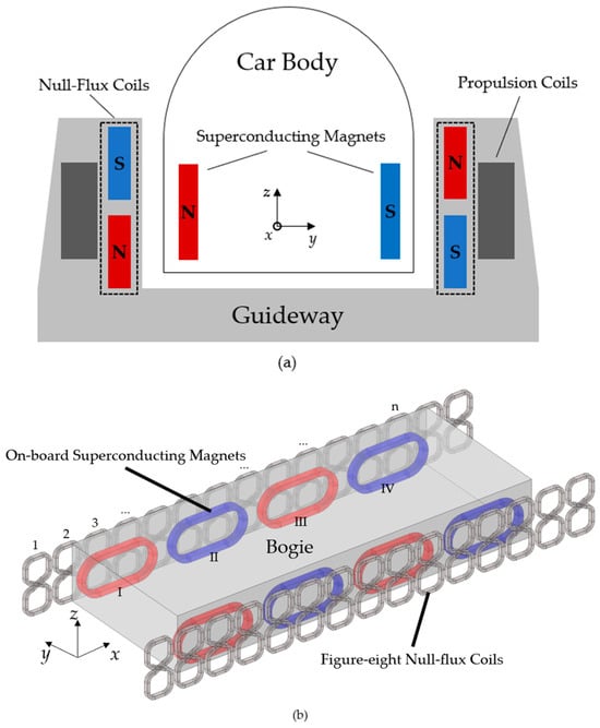
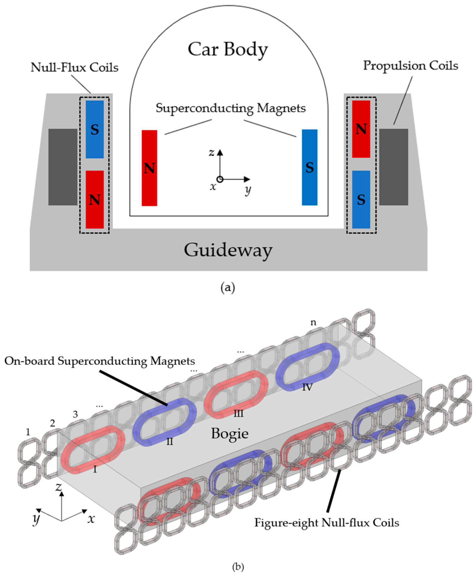
The suspension system of the EDS maglev mainly consists of onboard superconducting (SC) magnets, figure-eight null-flux coils, and propulsion coils. The vehicle is positioned in the center of the “U” shape track, with the null-flux coils and propulsion coils arranged on both sides of the track [27]. Generally, during normal operations, a constant current flows in the superconducting magnet, while the null-flux coils are not energized. When the vehicle moves, the magnetic field generated by the superconducting magnets is cut by the null-flux coils, generating an induced current. According to Lenz’s Law, the induced current in the coils always prevents changes in the magnetic field. As a result, the electromagnetic forces on the SC magnet can be divided into three components: an upward levitation force, a guidance force toward the center of the track, and a drag force opposing the vehicle’s motion. Understanding the magneto-electric force coupling relationship between the onboard SC magnet and the null-flux coils is crucial to improving the performance of the suspension system. The schematic diagram of the EDS system is shown in Figure 1.
Figure 1.
Schematic of the EDS system: (a) 2D cross-section of the guideway and the train; (b) 3D schematic of the maglev bogie and the null-flux coils (red and blue mean different magnetic field directions).
Many researchers have made efforts in order to better describe the relationship between SC magnets and null-flux coils. For example, researchers such as Murai et al. [24] and Takao et al. [25] tested the electromagnetic force measured on the Miyazaki test line and the Yamanashi test line in Japan, revealing the basic relationships in the suspension system. However, due to the limitations of real vehicle testing, more data and methods are required for further studies.
He et al. introduced dynamic circuit theory to calculate the electromagnetic force of the EDS system [28]. The method used equivalent-circuit models to transform the complex multiphysics coupled problem into a relatively simple task of solving specific circuit parameters. Despite certain limitations, it provided a theoretical basis for other studies. Calculating self-inductance and mutual inductance between coils is key to solving related problems. Based on this method, Cai et al. introduced the Neumann formula to calculate the mutual inductance between coils and studied the impact of specific circuit parameters on the vehicle under different operating conditions [29]. He et al. proposed a design for the EDS system without side walls, providing an approach to reducing construction costs [30]. The influence of induced current on null-flux coils on an SC magnet was studied by Azukizawa [31]. Yonezu et al. investigated the electromagnetic force characteristics acting on null-flux coils [32], and Mirzaei developed a spatial Fourier method to calculate the inductance of thin racetrack coils [33].
Compared with traditional methods, simulations using the finite element method (FEM) are better suited to solving complex multiphysics coupled problems. Gong et al. developed a 3D FEM model of the EDS system based on the vector magnetic potential method and revealed the characteristics of the electromagnetic force. Their model avoids moving mesh for onboard superconducting magnets and achieves high effectiveness [26]. Chen et al. and Guo et al. also built FEM models and discussed the force characteristics with different vertical and transverse displacements [34,35]. Huang et al. established the model by introducing a mixed A-V formulation and a field-circuit coupling method, and their method was capable of solving problems with lateral offsets [36]. FEM modeling has already become a commonly used method for studying the characteristics of the EDS system. The optimization of the EDS system has been a primary focus in recent years.
However, the impact of the shape of null-flux coils on the EDS maglev system has not been systematically studied before. Many studies focused on the optimization of the onboard SC magnet and the system performance in different operating situations [37,38,39], and the influence of different null-flux coil shapes on EDS maglev performance is rarely discussed.
To fill this research gap, this paper quantitatively investigates the influence of null-flux coil shape on the electromagnetic force characteristics of the EDS maglev system and establishes a shape–performance correlation model. It first analyzed the equivalent-circuit model of the null-flux coil in a non-cross-connected structure based on dynamic circuit theory, deriving and solving the system’s electromagnetic force using matrix transformation methods. Then, a three-dimensional finite element model of a single-sided EDS system was established, and the model was validated through comparisons with analytical calculations and test data from the reference. Finally, based on the validated FEM model, a systematic parametric study is carried out to quantify the effects of different null-flux coil shapes, particularly the rounded corner radius, on levitation, guidance, and drag force characteristics. The study lays the foundation for dynamic analysis of EDS maglevs and provides useful methods and insights for future optimization of the high-speed EDS maglev system.
2. Analytical Model and FEM Model
2.1. Analytical Model
Mechanical characteristics have decisive influences on the dynamic performance of EDS maglev systems. Understanding the relationship between the electromagnetic force on the superconducting magnet and factors such as operating speed, suspension height, and lateral offset is particularly crucial for the design and optimization of the system. Therefore, an equivalent analytical circuit model was built for the null-flux coils using dynamic circuit theory, and analytical equations for the electromagnetic force were derived. This analytical work lays the foundation for the following FEM.
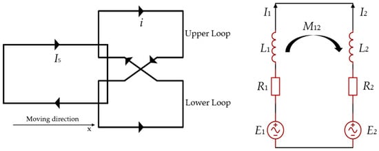
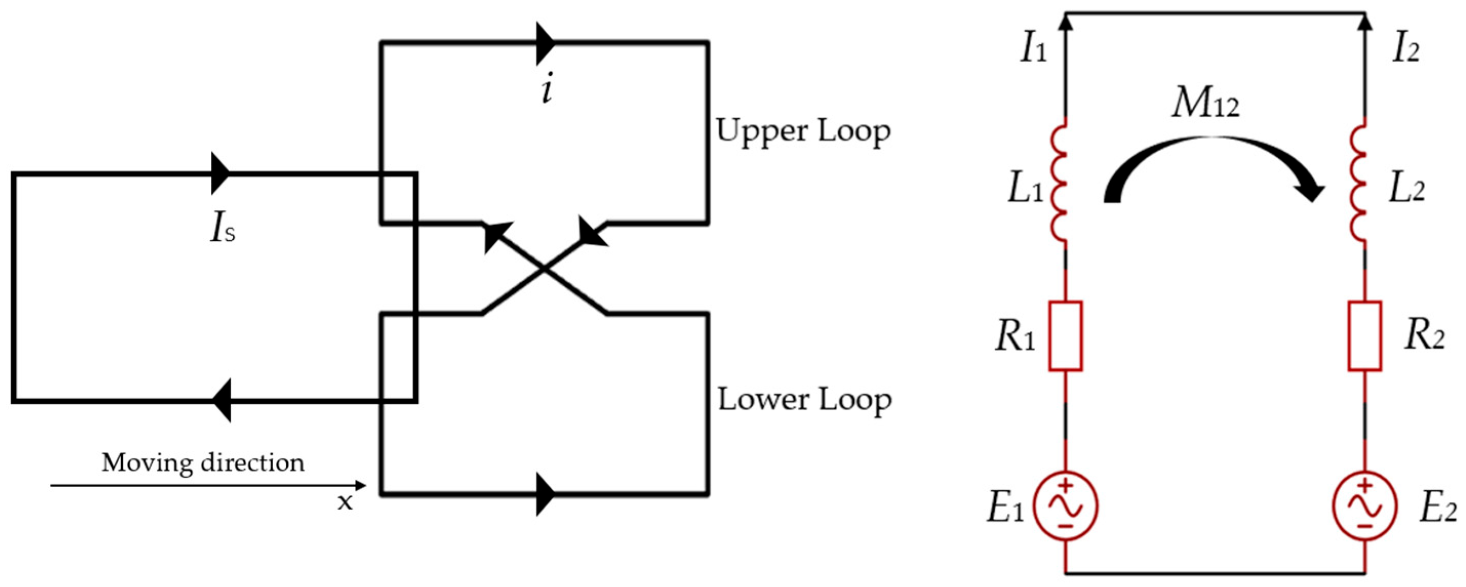
For null-flux coils, we only considered one side of the track, since the electromagnetic forces generated on both sides are symmetrical. The null-flux coils can be divided into two forms: cross-connected and non-cross-connected [40]. For a single coil without cross-connection, the 2D schema and its equivalent circuit are shown in Figure 2, where R1, R2 and L1, L2 are the equivalent resistance and inductance of the upper loop and the lower loop. I1 and I2 are the induced currents; E1 and E2 represent the induced electromotive force (EMF) in the upper loop and the lower loop; and M12 is the mutual inductance between the two loops. It is assumed that the system is operating under ideal conditions, where R = R1 = R2 and L = L1 = L2.
Figure 2.
Null-flux coil and its equivalent circuit.
Further on, we can introduce the superconducting magnet into this model. Thus, E1 and E2 can be described as follows:
where N1 and N2 are the number of turns of each loop, Is represents the value of current in the SC magnet, MS1 and MS2 are the mutual inductance between the SC magnet and the loops of the null-flux coil, and vx is the SC magnet’s speed in the x direction.
The circuit equation of such a null-flux coil can be written as
where i means the overall induced current in the null-flux coil.
The introduction of the SC magnet makes the system vary with both time and space. To simplify the calculation procedure and improve clarity, the original equations are written in matrix form. Based on the positional and structural relationships between the SC magnet and the null-flux coils, the voltage, current, inductance, and resistance matrices are defined as follows:
where ES and IS are the voltage and current sub-matrices for the superconducting magnet, EE and IE are the voltage and current sub-matrices for the null-flux coils, LS and LE are the inductance sub-matrices for the superconducting magnet and null-flux coils, and LSE and LES represent the mutual inductance sub-matrices between the superconducting magnet and null-flux coils. RS and RE are the resistance sub-matrices for both. It is important to note that, because of the zero-resistance characteristic of the superconducting magnet, RS is effectively a zero matrix.
The transformation matrix T is defined as follows:
where TS and TE are the current transformation sub-matrices of the SC magnet and null-flux coils. The purpose of introducing the transformation matrix is to express the branch voltages and currents in terms of a set of independent loop variables, so that changes in system inductance as well as the magnetic force can be calculated in a simpler way. The specific forms and structures of these sub-matrices depend on the connection arrangement between the coils. For example, given that the structure of the SC magnet remained unchanged during the whole simulation, its current had only one degree of freedom, and TS becomes a unit diagonal matrix.
Then, the system’s voltage equation can be written in the following matrix form:
where Gx, Gy, and Gz are the inductance variation rate matrices in three directions.
Finally, when the SC magnet moves in x direction, the electromagnetic forces generated can be described as
Notice that Equations (10)–(12) describe the situation when one SC magnet moves along one single null-flux coil; i represents the overall induced current in the null-flux coil. It can be extended to more complex situations with multiple coils.
From the above analysis, it can be seen that one of the main requirements for solving the electromagnetic force is determining the overall currents i in null-flux coils, which requires calculating the mutual inductance of the system. The mutual inductance mainly includes two parts: mutual inductance between the upper loops and the lower loops of null-flux coils, and mutual inductance between null-flux coils and the superconducting magnet. However, calculating the mutual inductance in such an electrodynamic system is relatively difficult by analytical methods. In the FEM, the calculation of the mutual inductance effect has already been merged in the software and has sufficient correctness.
For cross-connected null-flux coils, the calculation of electromagnetic force is similar to that of the non-cross-connected configuration [40]. Cross-connected null-flux coils usually have better guidance performance than non-cross-connected ones. In this article, the vehicle was placed at the exact center of the track at a fixed height, where the main function of the cross-connected configuration was not needed. Therefore, the model in this study was based on the non-cross-connected configuration, and the cross-connected configuration can be used for scenarios in which SC magnets constantly change their locations.
2.2. FEM Model
In this section, a finite element method (FEM) model of the suspension system was built. The model is based on MLX01, which was made in Japan and achieved the manned speed record of 581 km/h [41].
The suspension system of MLX01 mainly consists of the superconducting magnets and figure-eight null-flux coils. The superconducting magnets are placed symmetrically on both sides of the bogie, and they are wound with superconducting materials. Adjacent magnets are excited in the opposite direction, while the opposite magnets on two sides of the bogie are excited in the same direction. Generally, eight SC magnets are installed in one bogie of the EDS train.
During normal operation, a constant current flows through the SC magnet, creating a strong magnetic field. The null-flux coils are installed on the sidewalls along the guideway. The upper and lower loops of the null-flux coils are connected in reverse. When the SC magnet moves along, the effect between the SC magnet and the null-flux coils could be ignored if the center of the SC magnet is at the same height as that of the null-flux coils. In that case, there is no induced current in figure-eight coils, and thus no forces. When the center of the SC magnet is located below that of the null-flux coils, induced currents are generated in the null-flux coils, producing levitation force and guidance force for the vehicle.
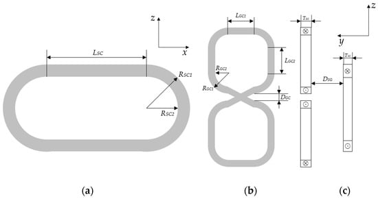
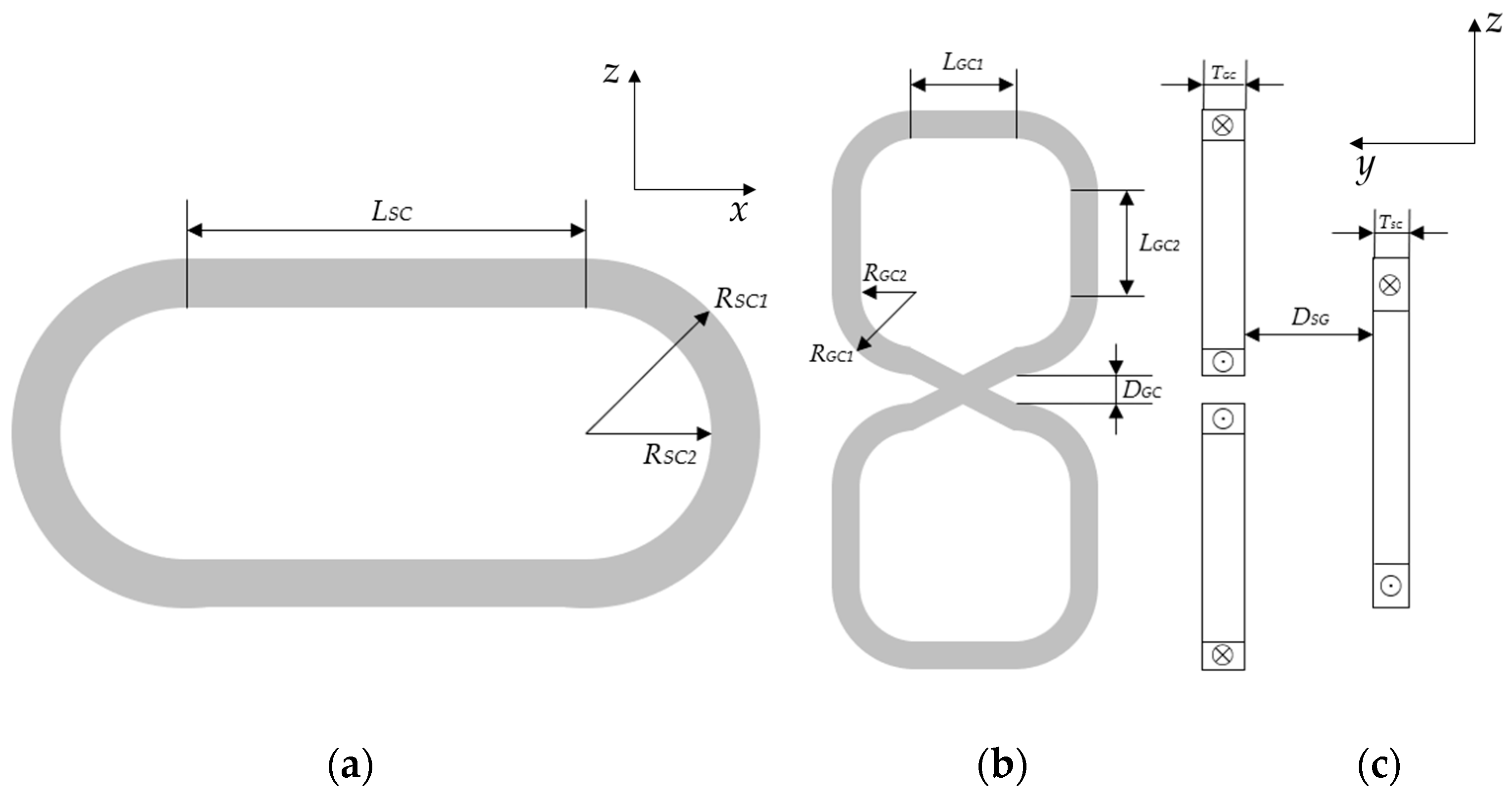
The parameters of the null-flux coils and the SC magnet are listed in Table 1. The 2D view of the SC magnet and the null-flux coil is shown in Figure 3.
Table 1.
Parameters of the EDS maglev model.
Figure 3.
Two-dimensional view of the SC magnet and the null-flux coil: (a) x–z view of SC magnet, (b) x–z view of null-flux coil, (c) z–y view of both.
In Table 1, inner radius and outer radius represent the minimum and maximum distances from the coil’s curved segment to its center. DGC is the minimum distance between the upper loop and the lower loop (before the cross part) of the null-flux coil. DSG is the minimum distance between the null-flux coil and the SC magnet. Figure 3 shows detailed geometrical parameters.
The FEM model mainly consisted of three parts: the null-flux coils, the SC magnet, and the air domain.
The air domain covered all the objects in this model. It was mainly used to calculate the magnetic field distribution. The air domain was divided into two parts, each containing the null-flux coils and the SC magnet. The two parts were set to be continuous, which effectively reduces the simulation time of the model.
In this model, the upper loops and the lower loops of the null-flux coils were physically connected. Small parts of the loops were replaced with crossed constructions to connect to one another. The advantage of this modeling method is that it is more closely aligned with real-world situations. By constructing the coil as a whole, it was more convenient to calculate the coil resistance and observe the induced current. Compared to another modeling method, in which the ec module is used to build external circuits to realize connections, this method slightly increased the calculation time. Most of the model was built in the rmm module.
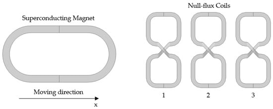
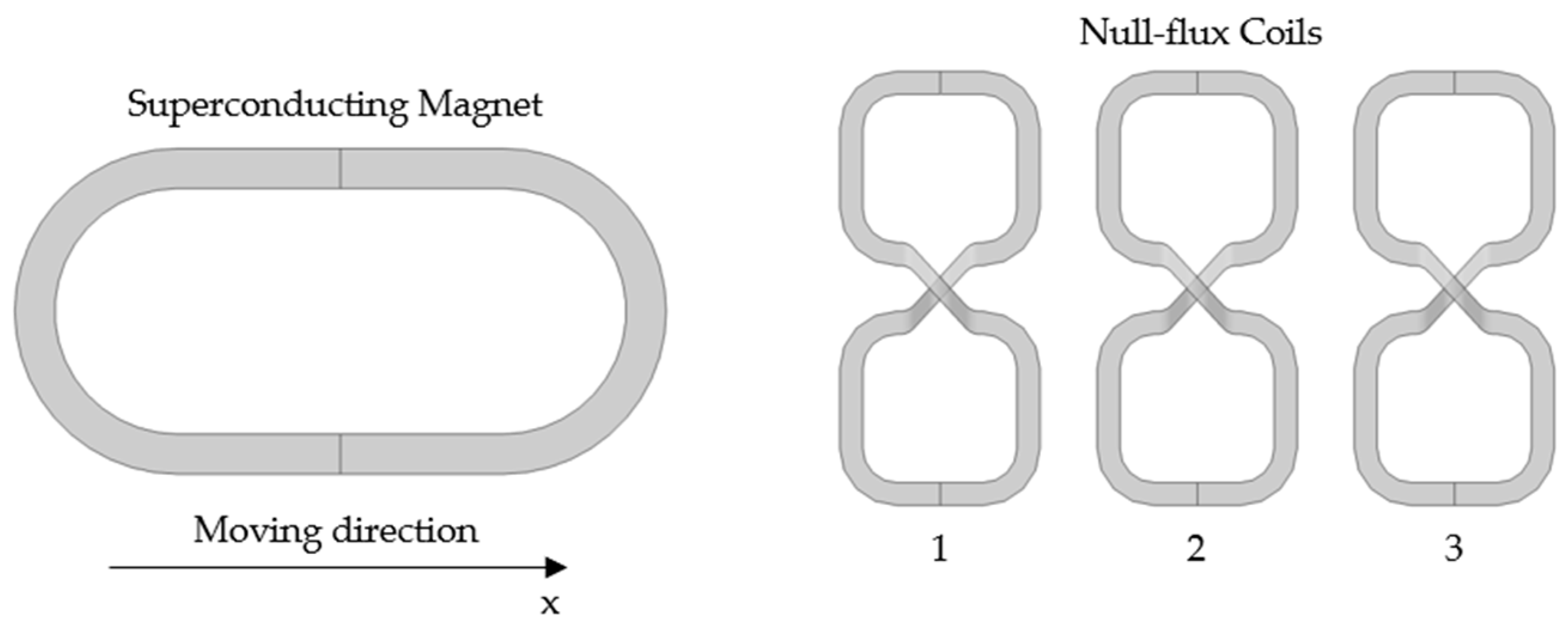
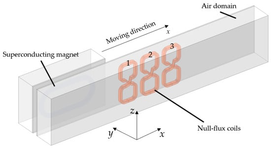
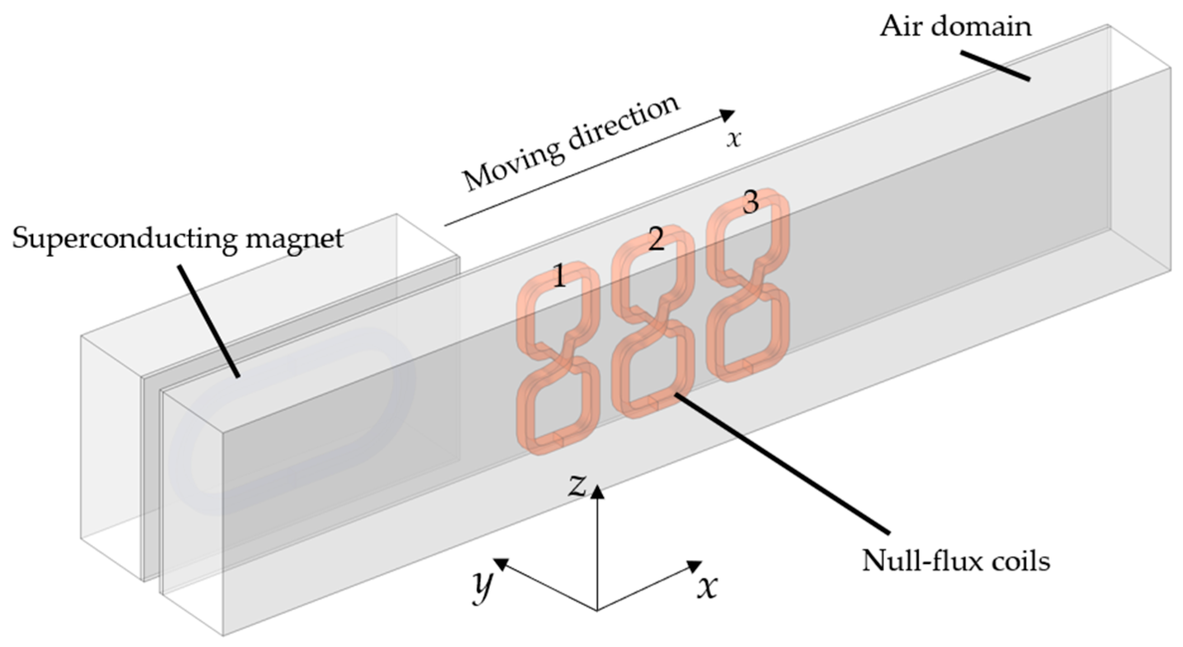
Figure 4 shows the schematic diagram of the SC magnet motion in FEM. The model contained three null-flux coils tagged from 1 to 3. It is assumed that the suspension system is operating under ideal conditions, meaning the SC magnet remains in a superconducting state. The resistance of the SC magnet is considered to be zero. In the rmm module, a constant current was set for the SC magnet. It was unnecessary to restrict the material of the SC magnet to certain superconductors according to this assumption.
Figure 4.
Schematic diagram of the SC magnet motion, and the air domain was hidden for better vision.
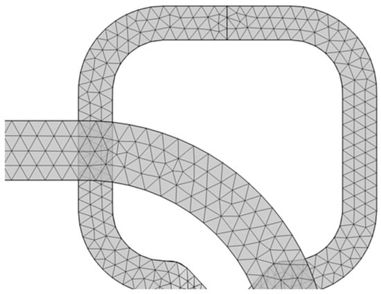
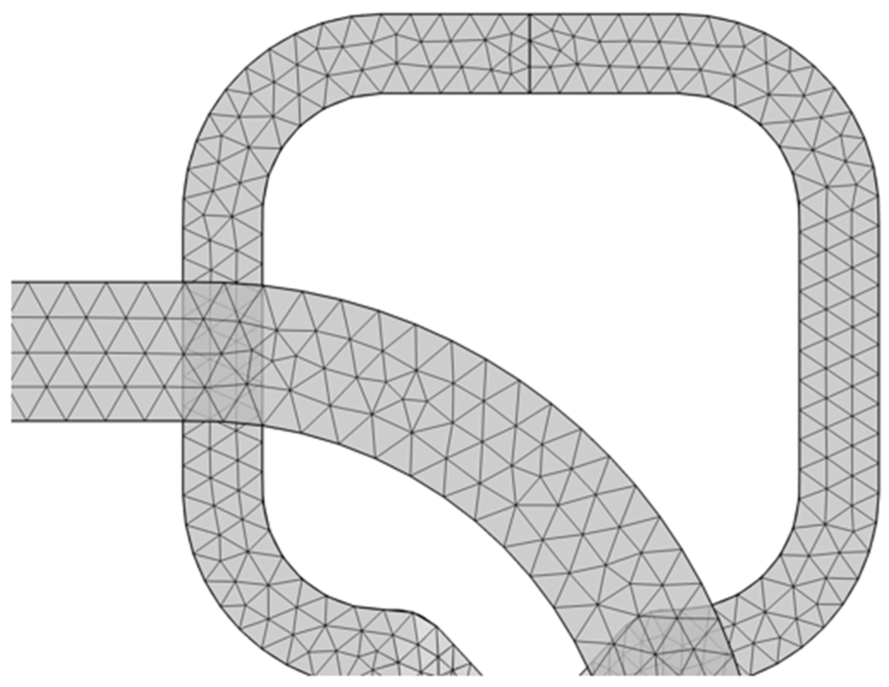
In this model, both null-flux coils and the SC magnet were meshed by restricting the maximum element size. The study focused on induced currents and electromagnetic forces; the element sizes of the null-flux coils were set to small values for better accuracy. For the remaining area of the air domain, larger element sizes were set to reduce the calculation time. The meshed model is partly shown in Figure 5. The complete FEM model is shown in Figure 6. The x-axis was defined as the direction of travel (longitudinal), the y-axis was the lateral axis, and the z-axis was the vertical axis.
Figure 5.
Mesh of the SC magnet and the null-flux coil.
Figure 6.
Full vision of the 3D FEM model.
In addition to the null-flux coils and the propulsion coils, there are damping coils in many EDS systems. Damping coils are set between SC magnets and null-flux coils, and are mainly used to improve the riding experience. In practical applications, they usually conduct electric currents and require active control. The control is based on the electromagnetic force of an SC magnet. The damping coils serve as auxiliary components in the system. In this study, damping coils have little impact on the investigation of different shapes of null-flux coils for superconducting EDS maglev in this study. Furthermore, introducing damping coils into the model would further increase complexity, resulting in extremely long calculation times. Therefore, damping coils are not included at this stage.
3. Results and Analysis
3.1. Model Validation
In the first simulation, default parameters were taken to validate the model. The speed of the SC magnet v was set to 200 km/h, and the minimum distance between the SC magnet and the null-flux coils DSG was 155 mm. The vertical displacement of the SC magnet △z was −40 mm, meaning the center of the SC magnet was lower than that of the null-flux coils. The size of coils remained the same, as shown in Table 1. The pole pitch of the SC magnets was three times that of the null-flux coils. Therefore, one SC magnet could be considered to be influenced by three null-flux coils. In this study, we simulated the case where a superconducting coil passed over three null-flux coils. During the simulation, the places of all objects except the superconducting magnet were fixed, and gravity was neglected.
In the software, rapidly changing values from moving objects are difficult to retrieve. In order to obtain the value of the electromagnetic force subjected to the SC magnet, we modeled the reaction force on the null-flux coils. Without the interference of other objects on the magnetic field, the electromagnetic force subjected to the bogie is approximately four times the force subjected to one pair of SC magnets [26], and thus one SC magnet is sufficient for the FEM model.
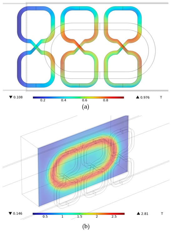
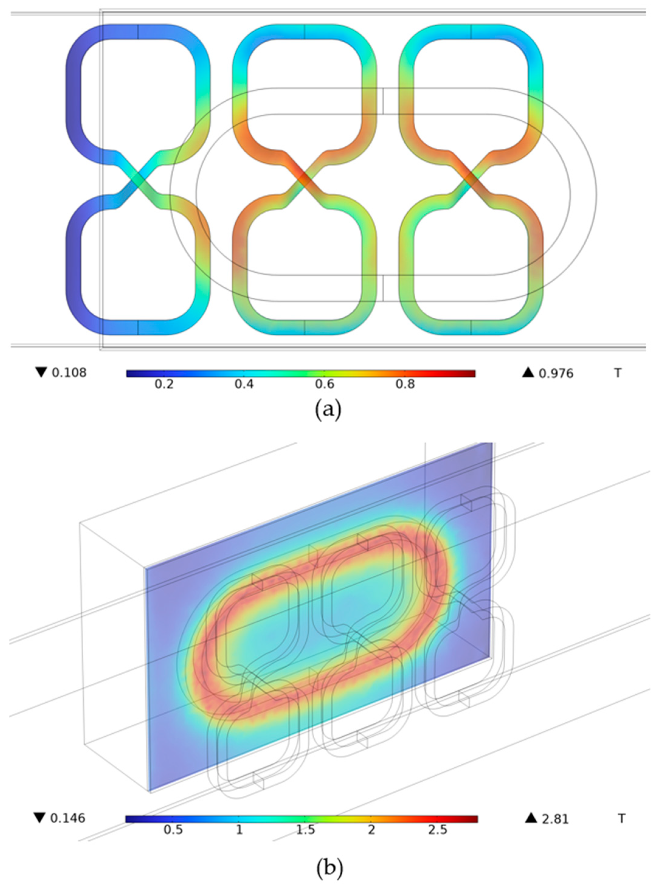
Figure 7a shows the magnetic flux density on the null-flux coils when the SC magnet passes by. Figure 7b shows the spatial density distribution of the air domain on the z–x plane. By observing the current flow in the null-flux coils, it can be proved that the physical connection is capable of the simulation.
Figure 7.
(a) Magnetic flux density on null-flux coils as the SC magnet passes by. (b) Magnetic flux density on the z–x plane of the SC magnet.
In order to validate the model, we simulated the electromagnetic forces acting on the SC magnet. The total reaction force acting on three null-flux coils was regarded as the electromagnetic force acting on the superconducting coil. The results were compared with the equivalent results from the Yamanashi Test Line [42] and calculated data according to the above equations.
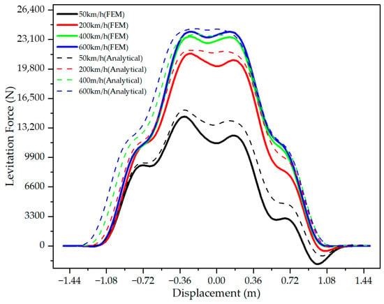
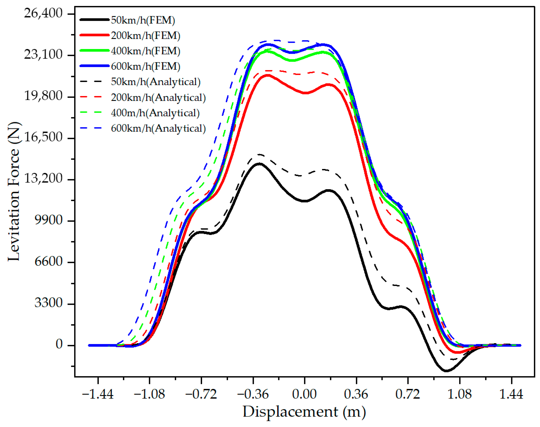
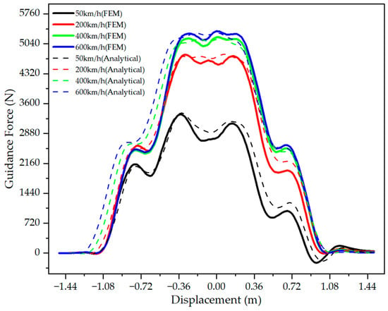
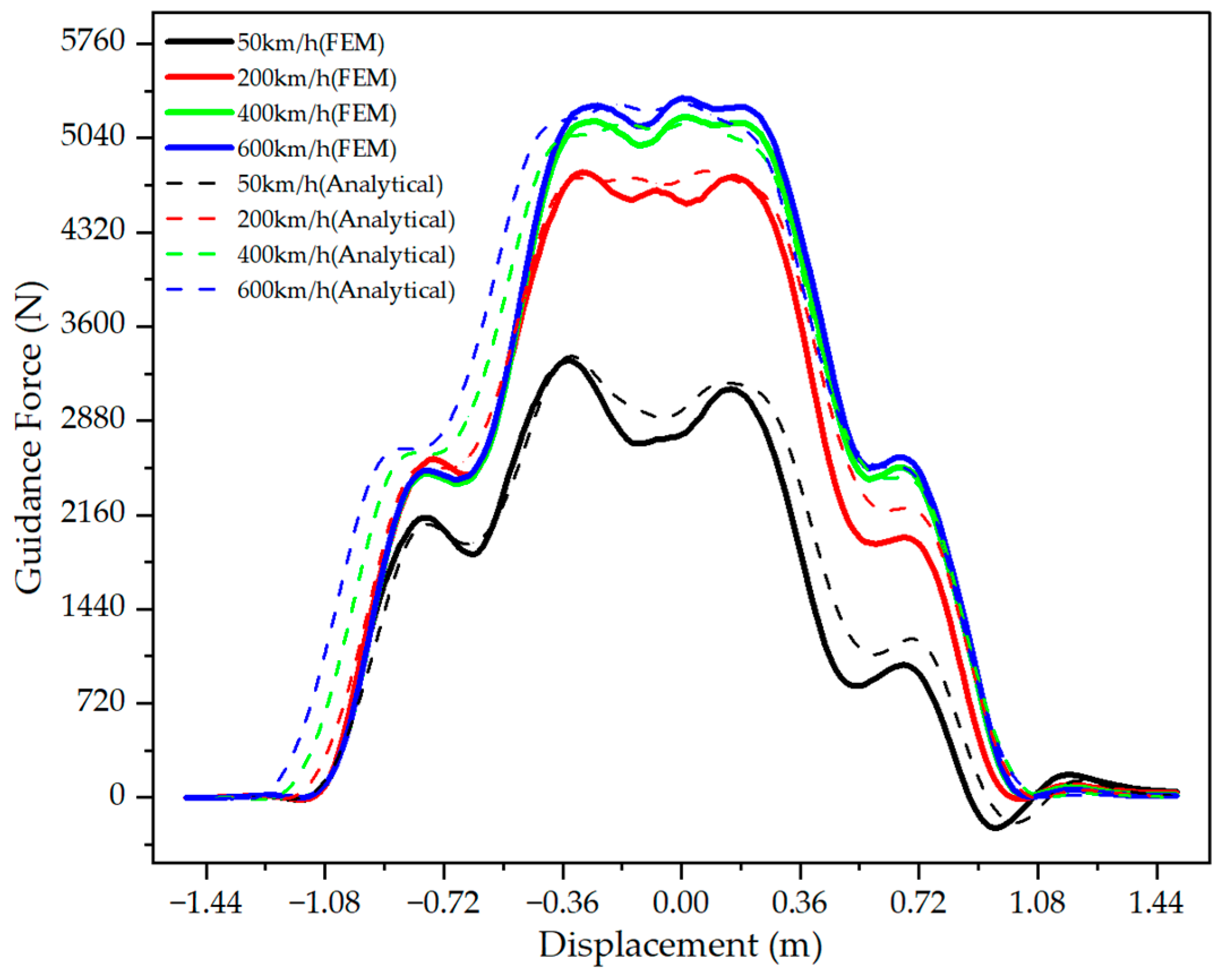
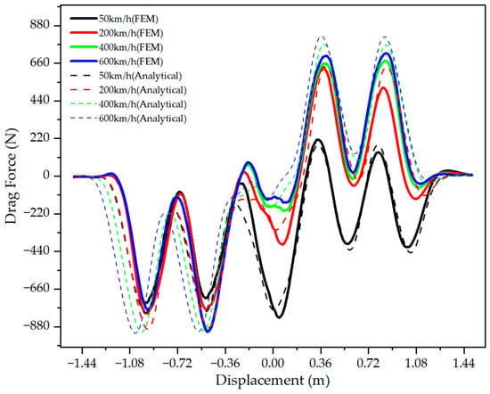
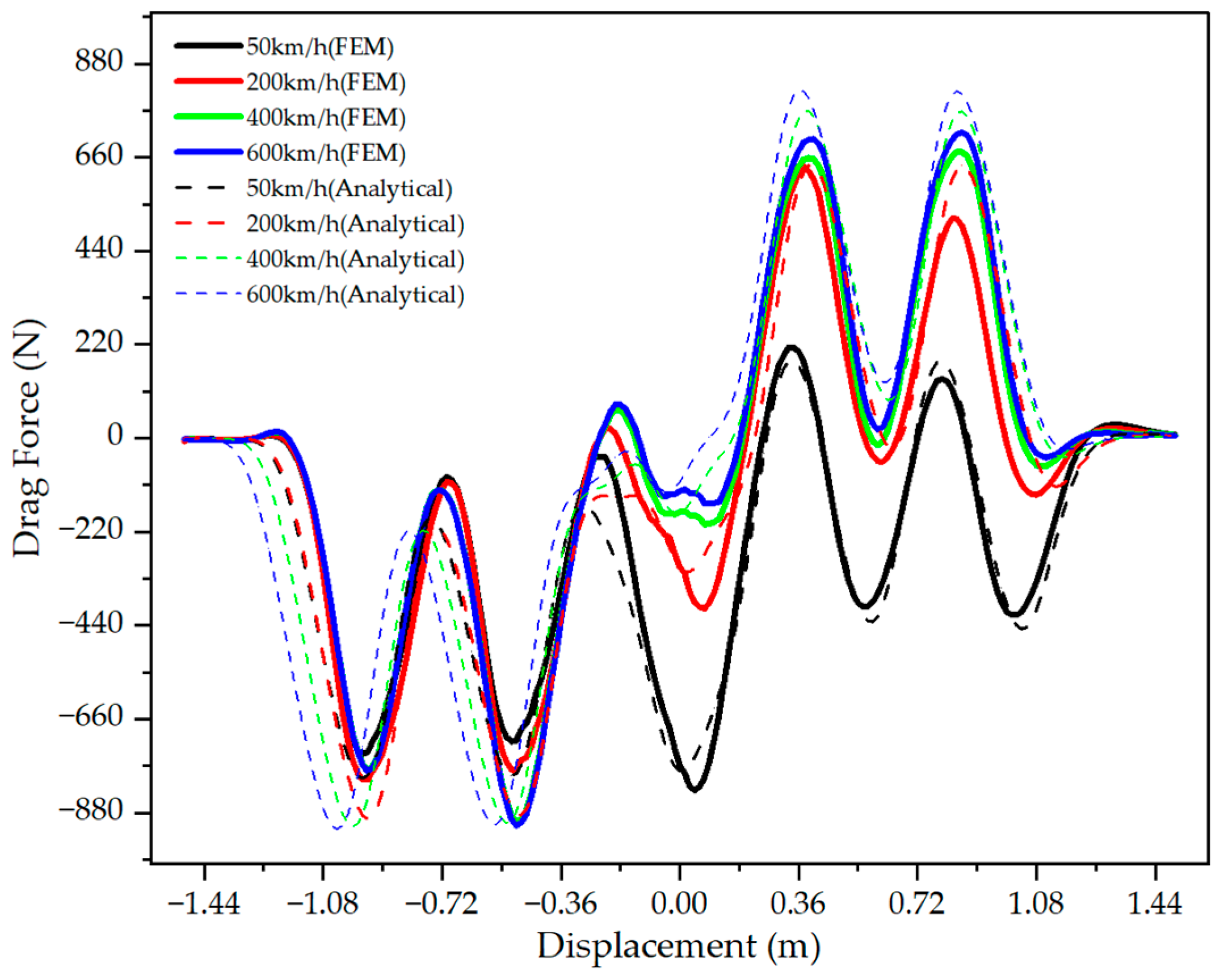
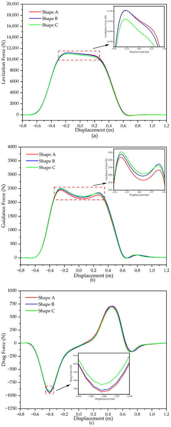
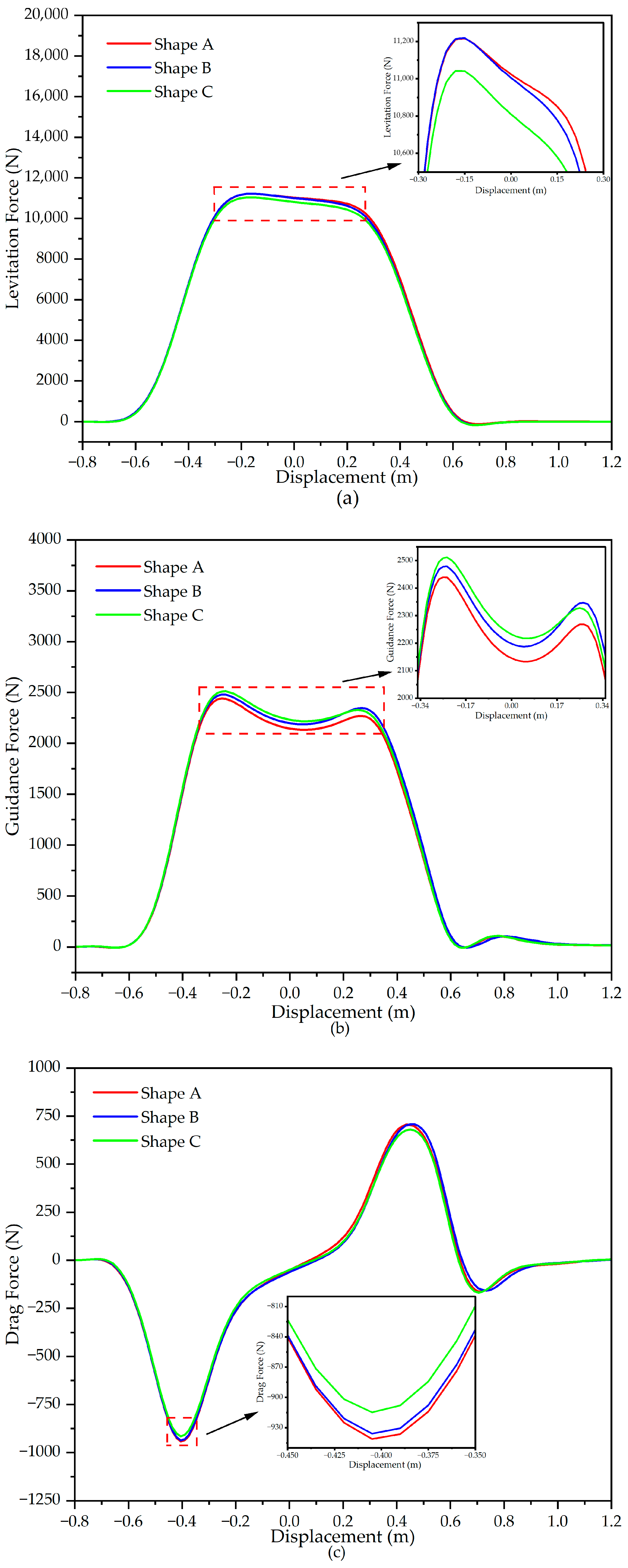
The results are shown in Figure 8, Figure 9 and Figure 10. The electromagnetic force can be divided into three directions: levitation force Fz, guidance force Fy, and drag force Fx. The magnet moves in the +x direction.
Figure 8.
Levitation force on the SC magnet.
Figure 9.
Guidance force on the SC magnet.
Figure 10.
Drag force on the SC magnet.
Figure 8 displays the relationship between levitation force and the operation speed of the SC magnet. By comparing simulation results and equivalent results from a real test, it was found that there was a difference between them. The reference data were converted into an equivalent single-magnet representation based on reasonable symmetry and coupling assumptions. On one hand, this equivalence may have neglected the complex electromagnetic coupling among adjacent superconducting magnets, as well as structural and installation-related effects in the real system. On the other hand, some minor factors were neglected in the model, including heat, supporting structures, and other devices that may affect the distribution of the magnetic field.
The dynamic circuit model (analytical calculation) cannot capture detailed electromagnetic phenomena, such as eddy currents and their losses, whereas the FEM can model them and present more realistic results. Overall, analytical calculation and FEM have good agreement despite some small differences. FEM can produce more reasonable and realistic results and was used for further analysis of the impact of different null-flux coil shapes in this study.
In Figure 8, the levitation force increased with the speed of the SC magnet. However, the increase in the levitation force of FEM tended to slow down at higher speeds, and eventually became nearly constant. For example, the difference between 200 km/h and 50 km/h is larger than that between 400 km/h and 200 km/h, or between 600 km/h and 400 km/h. The whole process can be described in two stages. During the first stage, where the force changed significantly with speed, the rate of change of magnetic flux in the null-flux coils increased accordingly. This phenomenon increased the induced current and consequently led to a continuous increase in the levitation force. In the second stage, as the speed continued to increase, the frequency (change rate) of the induced current increased, and the current gradually became concentrated near the surface of the conductor. This phenomenon was similar to the skin effect, which increased the equivalent impedance of the coil and restricted the current by further increasing, and thus stabilized the levitation force [35].
The guidance force of the SC magnet followed a similar change rule to that of the levitation force. Notice that the results of the guidance force in Figure 9 were calculated based on one side of the guideway. The guidance forces generated by both sides of the guideway are symmetrical. Therefore, the total guidance force can be calculated in a double-sided guideway.
The drag force on the SC magnet contained several peaks, including both positive and negative components. Negative components of the drag force oppose the motion of the SC magnet, while positive components promote it. In Figure 10, as the speed increased, the magnitude of the positive components increased. This indicates that the overall drag force acting on the SC magnet decreased with speed. When the SC magnet passes by at a relatively slow speed, there is sufficient time for the induced current in null-flux coils to increase to its maximum value, resulting in a large drag force. However, the time required decreases as the magnet moves faster. When the SC magnet passes by at a relatively high speed, the induced current cannot reach its maximum value before the magnet leaves, causing a decrease in drag force. Such characteristics of drag force are beneficial for the application of the EDS system at ultra-high speed levels.
Notice that the force characteristics were not strictly symmetric with respect to the zero-displacement position. This phenomenon mainly originates from the coupling effects among multiple null-flux coils, which make the mutual inductance between the SC magnet and the null-flux coils not strictly symmetric about the center position. Since electromagnetic forces are directly determined by the spatial distribution and gradient of mutual inductance, the force characteristics consequently exhibited asymmetries.
Considering that each three-dimensional transient FEM simulation with parametric variations in both geometry and operating conditions is highly time-consuming, a comprehensive investigation of multiple offset cases would significantly increase the computational complexity. Therefore, the influence of coil shape on different suspension heights and lateral offsets is not included at this stage. The combined geometric and operational parameter variations will be systematically investigated in future work.
3.2. Impact of Null-Flux Coil Shape
The shape of null-flux coils is one factor affecting electromagnetic force characteristics. This section aims to quantify how this geometric transformation affects force generation and the performance of the system. The study was conducted through comparative simulations. It focused on the transition from a rectangular to a circular coil configuration and its impact on the electromagnetic force.
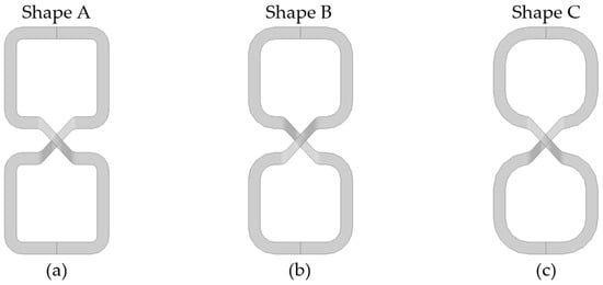
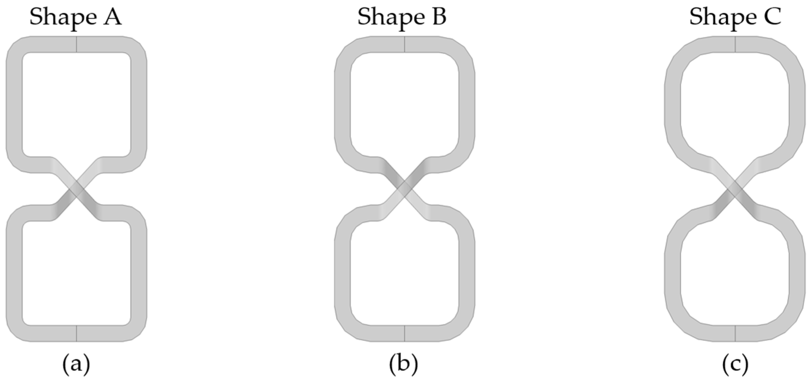
The parameter RGC1 is used to describe the shape of a null-flux coil, which means the outer radius of its rounded corners. When changing RGC1, the value of RGC1 − RGC2 is set to a constant of 40 mm, keeping the coil’s cross-sectional area constant. Under this constraint, the geometry of the coil changes from a rounded rectangle to nearly a circle as RGC1 increases. We modeled the force of the SC magnet for several values of RGC1. Figure 11 shows how RGC1 affects the shape of the null-flux coil. Three typical shapes were tagged as shape A, shape B, and shape C.
Figure 11.
Different shapes of null-flux coils: (a) shape A, RGC1 = 60 mm; (b) shape B, RGC1 = 90 mm; (c) shape C, RGC1 = 120 mm.
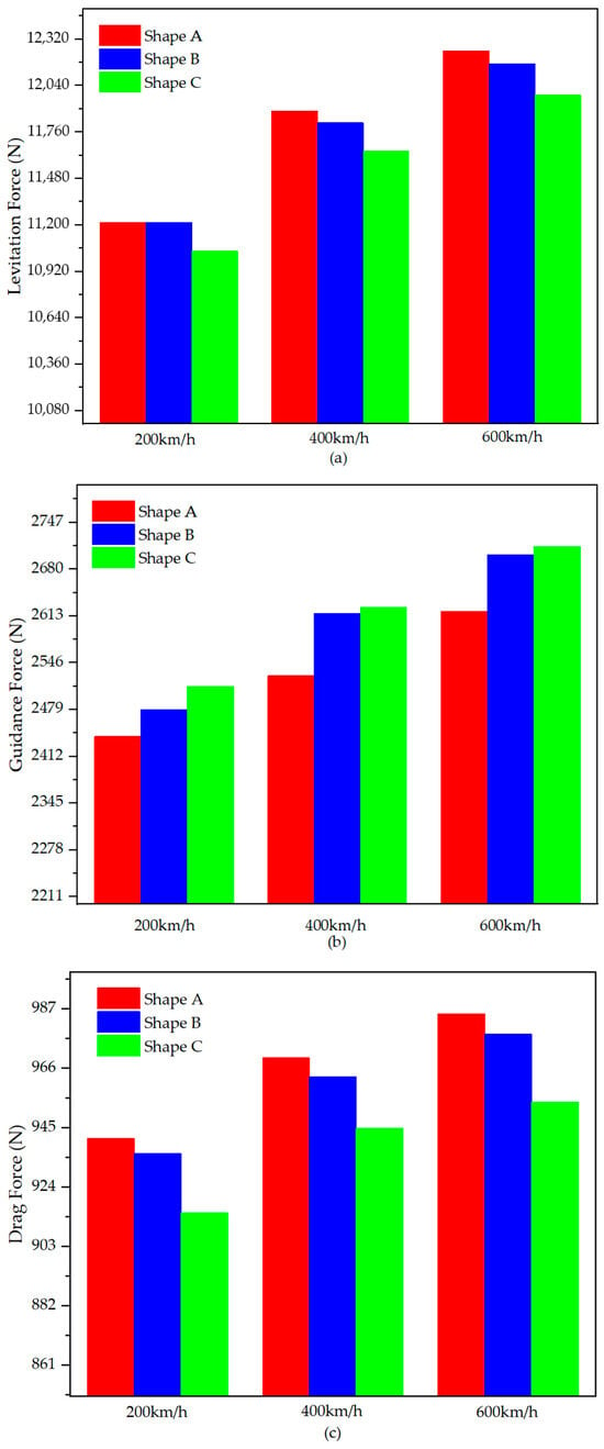
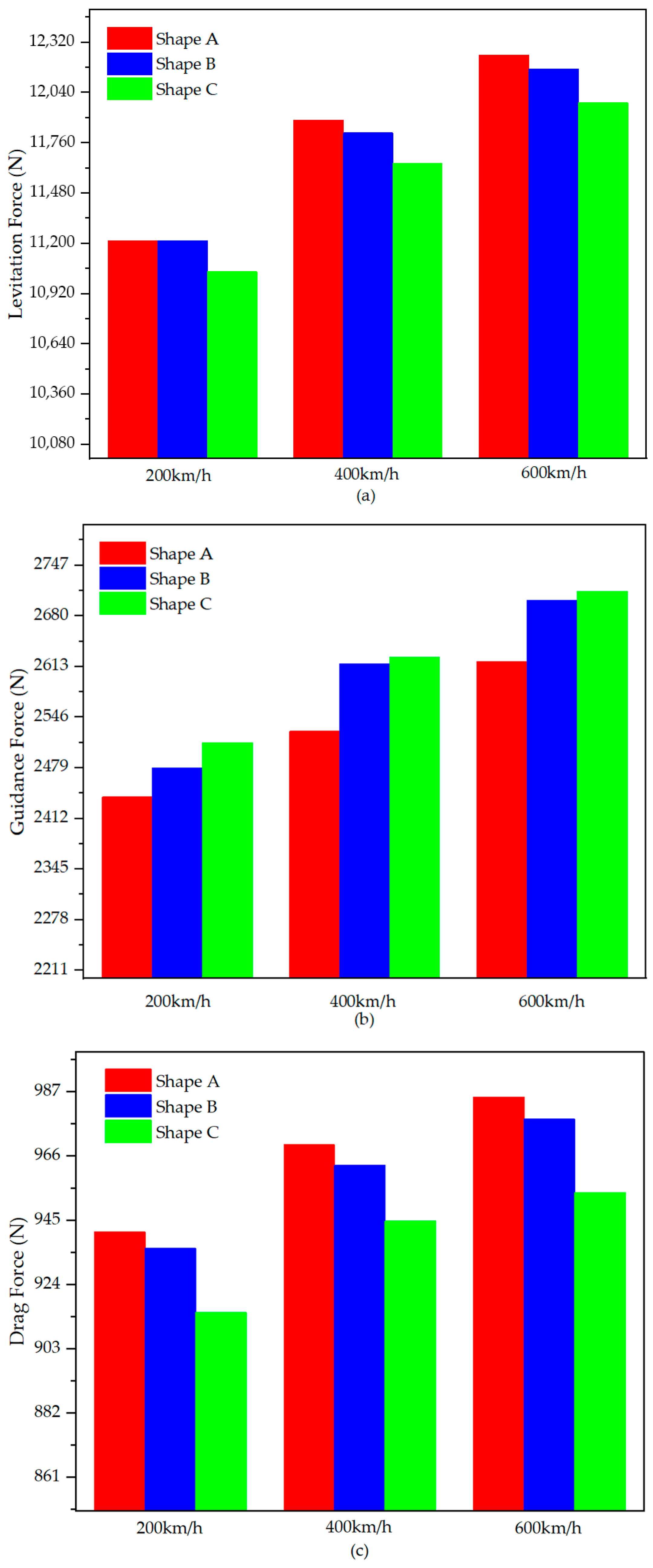
Figure 12 shows how the electromagnetic force on null-flux coil NO. 2 (Figure 4) varied with time for different values of RGC1, including levitation force Fz, guidance force Fy, and drag force Fx. Since the influence of coil shape on the electromagnetic force is difficult to distinguish when multiple coils are involved, the following analysis focused on the variation in the electromagnetic force acting on a single null-flux coil. The specific numerical comparisons of the three forces are shown in Figure 13. The force data were taken as the maximum value during the simulation.
Figure 12.
Electromagnetic force on null-flux coil NO. 2 vs. time with different null-flux coil shapes, the speed of the SC magnet was 200 km/h: (a) levitation force Fz; (b) guidance force Fy; (c) drag force Fx.
Figure 13.
Comparison of electromagnetic forces on null-flux NO. 2 among coil shapes A, B, and C of different operation speeds: (a) levitation force Fz; (b) guidance force Fy; (c) drag force Fx.
From Figure 12 and Figure 13, the results show that as the corner radius of the null-flux coils increased, both the levitation and drag forces decreased slightly, whereas the guidance force increased. In particular, at the speed of 200 km/h, the levitation force generated by shape A was approximately 1.58% greater than that of shape C, and the drag force was approximately 2.87% greater. The guidance force increased by approximately 2.95%. The differences at 400 km/h and 600 km/h showed a similar pattern to those at 200 km/h.
Figure 13 also shows that regardless of the speed conditions, the shape of the null-flux coil had a similar influence on the electromagnetic force. One possible reason the coil shape affects the electromagnetic force is a change in the magnetic flux linkage of the coil.
According to Maxwell’s equations, the magnetic flux linked with the null-flux coil is determined by the magnetic field generated by the SC magnet and the effective enclosed area of the null-flux coil loop. In this model, as the radius of the null-flux coil increased, the sharp corners gradually became smoother. This geometric change may leads to a reduction in the effective flux linkage of both the upper and lower loops. As a result, the mutual inductance between the SC magnet and the null-flux coil decreases, thereby weakening the electromagnetic force. The different variation in the mutual inductance gradient in the y direction caused by model geometry may contribute to the increase in guidance force in the results.
Based on above analysis, the levitation force and drag force were mainly governed by the variation of magnetic flux linkage and mutual inductance in vertical and longitudinal directions. Therefore, it can be expected that the influence of coil shape on levitation force and drag force would show similar trends for cross-connected coils. However, the cross-connected configuration introduces additional current coupling and redistribution in lateral direction. As a result, the guidance force may exhibit different characteristics. The effects of coil shape on the cross-connected configuration will be further studied.
The situation of a perfect-square coil was not modeled since right angles would cause divergence. The relationship between the electromagnetic force and RGC1 indicates that rectangular null-flux coils are typically preferred in suspension systems, as they exhibit better levitation performance.
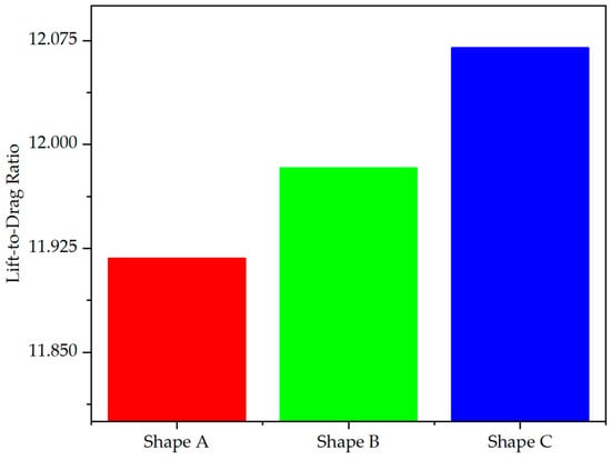
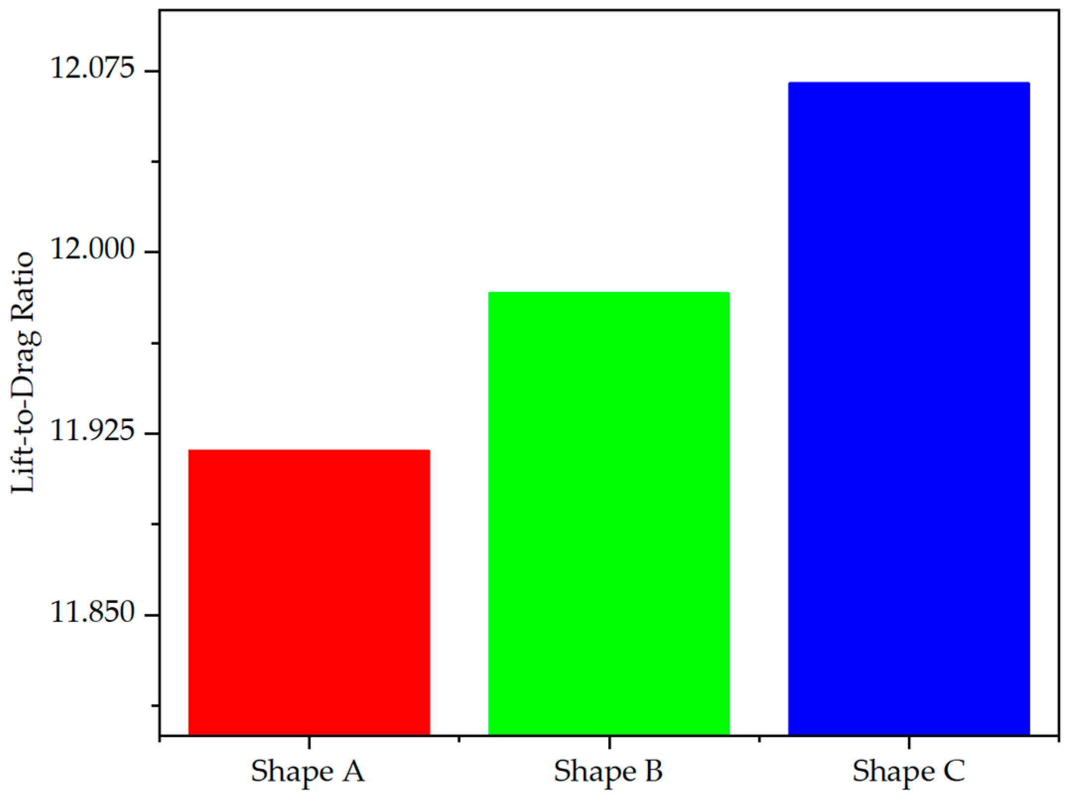
Figure 14 shows the lift-to-drag ratio for different values of RGC1 at 200 km/h. It was calculated by dividing the maximum value of the levitation force by the maximum value of the drag force. The relatively small lift-to-drag ratio is reasonable in this study, as the enhancement of levitation force and the reduction in drag force due to multi-coil coupling are not included in a single-magnet case. As shown in Figure 14, as RGC1 increased, the system’s lift-to-drag ratio also increased. The results show that as increasing RGC1 leads to a change in overall electromagnetic force, it improves the efficiency of the suspension system at the same time.
Figure 14.
Lift-to-drag ratio of different values of RGC1 at 200 km/h.
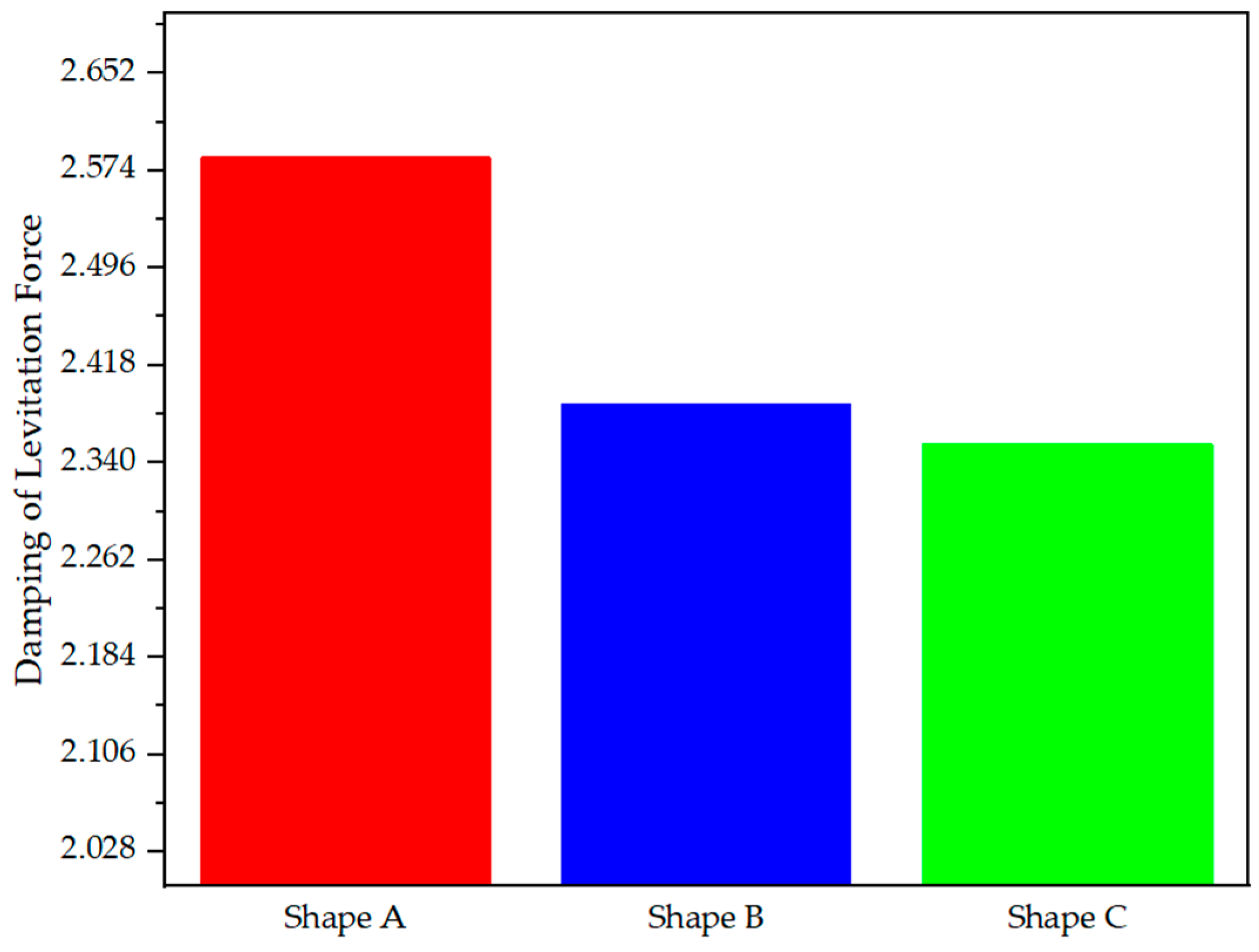
The damping of the electromagnetic force is also an important indicator of the performance of the EDS maglev systems. For example, the damping of the levitation force shows the ability to respond to different operation speeds. In analytical calculations, the specific value of damping is difficult to obtain since it is related to multiple factors, such as the geometry of coils and the magnetomotive force [43]. FEM provides an efficient way to calculate damping and quickly compare results across different operation speeds. The damping of the levitation force can be calculated using Equation (13).
where czx represents the damping of the levitation force. It was supposed that the original operation speed of the SC magnet was v0. Then, an offset of ∆v was applied to the model. Consequently, a damping solution could be derived from the results of new simulations. The comparison of the damping of the levitation force among coil shapes A, B, and C is shown in Figure 15. The damping value is sensitive to the selected force evaluation interval; therefore, the result should be regarded as a reference value. In Figure 15, v0 was taken as 400 km/h, and ∆v was taken as 200 km/h.
Figure 15.
Damping of the levitation force of three different null-flux coil shapes.
According to Figure 15, the damping of the levitation force on the SC magnet decreased as RGC1 increased. It is reasonable because coil shape A, which was more similar to a rectangular shape, had a larger magnetic flux area and longer coil length. In particular, the damping of the levitation force of coil shape A was approximately 10% greater than that of shape C.
4. Conclusions
This article presents a novel study on the impact of the shape of null-flux coils on the EDS maglev system. A finite element model of an EDS maglev system was built. Through model validation and simulation, the relationship between the shape of the figure-eight null-flux coils and the electromagnetic forces in the system was studied. The results show that as the radius of the curved segments in the upper and lower loops of the null-flux coils increased, both the levitation and drag forces decreased, while the guidance force increased. It also showed a higher lift-to-drag ratio and lower damping of the levitation force. This phenomenon could possibly be explained by the change in the overall inductance of the coil as well as the change in magnetic flux.
The shape of null-flux coils has an influence on the performance of EDS maglev systems. It can be seen that rectangular null-flux coils performed slightly better than circular ones in levitation. However, perfectly sharp corners are not recommended in practical applications due to potential current distortion and other undesirable effects.
The model in this article is applicable across a wide range of speeds and is particularly suitable for research on high-speed EDS superconducting maglevs operating at speeds of 600 km/h and above. For different situations, such as guideways with slight curves, further investigation is required since the magneto-electric force coupling is much more complicated. Both the analytical calculation and the modeling approach need to be reconsidered. Limitations of this study include the need for further experimental validation and actual EDS maglev prototype tests, as well as more analysis of different null-flux coil shapes across scenarios with different SC magnet offsets and suspension heights. For future work, more in-depth research on the stiffness and damping of electromagnetic forces at different speeds and under deviation conditions, such as curved guideways, can be carried out. In summary, the novel investigation and analysis presented in this article offer useful methods and inspiration for future optimization of null-flux coils and the overall electrodynamic performance of the superconducting EDS maglev system.
Author Contributions
Conceptualization, B.S. and L.F.; methodology, H.S., B.S., and Z.C.; software, H.S. and Z.C.; validation, H.S. and L.F.; writing—original draft preparation, H.S. and B.S.; writing—review and editing, B.S. and L.F.; supervision, B.S. and L.F.; project administration, L.F. All authors have read and agreed to the published version of the manuscript.
Funding
This work was supported in part by the National Natural Science Foundation of China under Grant No. 52407025 and the Fundamental Research Funds for the Central Universities.
Institutional Review Board Statement
Not applicable.
Informed Consent Statement
Not applicable.
Data Availability Statement
The data presented in this study are available on request from the corresponding author.
Conflicts of Interest
The authors declare no conflicts of interest.
Abbreviations
The following abbreviations are used in this manuscript:
| ec | Electric Current |
| EDS | Electrodynamic Suspension |
| EMS | Electromagnetic Suspension |
| FEM | Finite Element Method |
| GC | Ground Coil |
| mf | Magnetic Field |
| rmm | Rotating Machinery, Magnetic |
| SCM | Superconducting Magnet |
| SPL | Superconducting Pinning Levitation |
References
- Lu, L.; Wu, W.; Yu, X.; Jin, Z. High-Temperature Superconducting Non-Insulation Closed-Loop Coils for Electro-Dynamic Suspension System. Electronics 2021, 10, 1980. [Google Scholar] [CrossRef] [Scilit]
- Yin, M.; Li, Y.; Wang, Z.; He, Y.; Li, H.; Deng, Z. Dynamic Analysis of Levitator Failure in HTS Pinning Maglev Vehicle. IEEE Trans. Appl. Supercond. 2025, 35, 1–9. [Google Scholar] [CrossRef] [Scilit]
- Yan, L. Suggestion for Selection of Maglev Option for Beijing-Shanghai High-Speed Line. IEEE Trans. Appl. Supercond. 2004, 14, 936–939. [Google Scholar] [CrossRef]
- Li, F.; Sun, Y.; Xu, J.; He, Z.; Lin, G. Control Methods for Levitation System of EMS-Type Maglev Vehicles: An Overview. Energies 2023, 16, 2995. [Google Scholar] [CrossRef] [Scilit]
- Goodall, R. Dynamics and Control Requirements for EMS Maglev Suspensions. In Proceedings of the 8th International Symposium on Magnetic Suspension Technology (ISMST-8), Dresden, Germany, 13–17 September 2004. [Google Scholar]
- Okano, M.; Iwamoto, T.; Furuse, M.; Fuchino, S.; Ishii, I. Running Performance of a Pinning-Type Superconducting Magnetic Levitation Guide. J. Phys. Conf. Ser. 2006, 43, 999. [Google Scholar] [CrossRef] [Scilit]
- Zhou, X.; Luo, Y.; He, Y.; Peng, C.; Zeng, P.; Li, Y.; Deng, Z. Damping Characteristics of High-Temperature Superconducting Pinning Maglev Levitation System. Cryogenics 2024, 141, 103892. [Google Scholar] [CrossRef] [Scilit]
- Wang, G.; Fu, L.; Chen, Y.; Zhan, Y.; Yue, J.; Chen, X.; Shen, B. Low-carbon hydrogen-electricity energy supply networks for China-Thailand international high-speed railway. Energy 2026, 344, 139940. [Google Scholar] [CrossRef] [Scilit]
- Fu, L.; Chen, Y.; Li, S.; Zhang, M.; Jiang, S.; Chen, X.; Shen, B. Hydrogen-Electricity Hybrid-Energy System with Superconducting-Battery Energy Storage for Urban Rail Transit: Design, Case Study, and Techno-Economic Analysis. Appl. Energy 2026, 405, 127198. [Google Scholar] [CrossRef] [Scilit]
- Yao, C.; Ma, Y. Superconducting Materials: Challenges and Opportunities for Large-Scale Applications. iScience 2021, 24, 102541. [Google Scholar] [CrossRef] [Scilit] [PubMed]
- Kitazawa, K. Superconductivity: 100th Anniversary of Its Discovery and Its Future. Jpn. J. Appl. Phys. 2011, 51, 010001. [Google Scholar] [CrossRef] [Scilit]
- Chen, Y.; Chen, X.; Fu, L.; Jiang, S.; Shen, B. Superconducting Hydrogen-Electricity Multi-Energy System for Transportation Hubs: Modeling, Technical Study and Economic-Environmental Assessment. Appl. Energy 2025, 401, 126823. [Google Scholar] [CrossRef] [Scilit]
- Fujie, J. Superconductive Magnetically Levitated Railway, and Power-Feed System Therefor 1993. U.S. Patent 5,189,961, 2 March 1993. [Google Scholar]
- Fujiwara, S.; Fujie, J. Levitation-Propulsion Mechanism for Inductive Repulsion Type Magnetically Levitated Railway 1988. U.S. Patent 4,779,538, 25 October 1988. [Google Scholar]
- Coffey, H.T.; Chilton, F.; Hoppie, L.O. Feasibility of Magnetically Levitating High Speed Ground Vehicles; Final Report on Task 1; Stanford Research Inst.: Menlo Park, CA, USA, 1972. [Google Scholar]
- Aiba, M. Development of the Ground Coil for Practical Use by the Combined Propulsion, Levitation and Guidance System. Proc. MAGLEV 2004, 2004, 849–855. [Google Scholar]
- Powell, J.R. High-Speed Transport by Magnetically Suspended Trains. ASME Pap. 1966, 66, 1. [Google Scholar]
- Andriollo, M.; Martinelli, G.; Moisio, M.F.; Morini, A. Calculation of Propulsion Forces in EDS-MAGLEV Transport Systems with Superconducting Coils. Arch. Für Elektrotechnik 1989, 72, 333–339. [Google Scholar] [CrossRef] [Scilit]
- Lv, G.; Liu, Y.; Zhang, Z.; Li, X. Numerical Analysis of the Rotational Magnetic Springs for EDS Maglev Train. CES Trans. Electr. Mach. Syst. 2022, 6, 60–66. [Google Scholar] [CrossRef] [Scilit]
- Burkhardt, E.E.; Schwartz, J.; Nakamae, S. Analysis of Superconducting Magnet (SCM)-Ground Coil Interactions for EDS Maglev Coil Configurations. IEEE Trans. Appl. Supercond. 1993, 3, 430–433. [Google Scholar] [CrossRef]
- Bernstein, P.; Noudem, J. Superconducting Magnetic Levitation: Principle, Materials, Physics and Models. Supercond. Sci. Technol. 2020, 33, 033001. [Google Scholar] [CrossRef] [Scilit]
- Murai, T.; Iwamatsu, M.; Yoshioka, H. Optimized Design of 8-Figure Null-Flux Coils in EDS Maglev. IEEJ Trans. Ind. Appl. 2004, 123, 9–14. [Google Scholar] [CrossRef] [Scilit]
- Ono, M.; Koga, S.; Ohtsuki, H. Japan’s Superconducting Maglev Train. IEEE Instrum. Meas. Mag. 2002, 5, 9–15. [Google Scholar] [CrossRef] [Scilit]
- Murai, T.; Fujimoto, T.; Fujiwara, S. Test Run of Combined Propulsion, Levitation and Guidance System at Miyazaki Test Track. Electr. Eng. Jpn. 1996, 117, 68–79. [Google Scholar] [CrossRef] [Scilit]
- Takao, S.; Mizutani, T.; Shirakuni, N.; Kozu, M. Vehicle-Running Tests and Development on the Yamanashi Maglev Test Line. Q. Rep. RTRI 2004, 45, 3–6. [Google Scholar] [CrossRef] [Scilit]
- Gong, T.; Ma, G.; Wang, R.; Li, S.; Yao, C.; Xiao, L. 3-D FEM Modeling of the Superconducting EDS Train With Cross-Connected Figure-Eight-Shaped Suspension Coils. IEEE Trans. Appl. Supercond. 2021, 31, 3600213. [Google Scholar] [CrossRef] [Scilit]
- Huang, H.; Li, H.; Coombs, T.; Zhu, H.; Sun, Y.; Lin, G.; Xu, J.; Zheng, J. Advancements in Dynamic Characteristics Analysis of Superconducting Electrodynamic Suspension Systems: Modeling, Experiment, and Optimization. Superconductivity 2024, 11, 100114. [Google Scholar] [CrossRef] [Scilit]
- He, J.L.; Rote, D.M.; Coffey, H.T. Applications of the Dynamic Circuit Theory to Maglev Suspension Systems. IEEE Trans. Magn. 1993, 29, 4153–4164. [Google Scholar]
- Cai, Y.; Ma, G.; Wang, Y.; Gong, T.; Liu, K.; Yao, C.; Yang, W.; Zeng, J. Semianalytical Calculation of Superconducting Electrodynamic Suspension Train Using Figure-Eight-Shaped Ground Coil. IEEE Trans. Appl. Supercond. 2020, 30, 3602509. [Google Scholar] [CrossRef] [Scilit]
- He, J.L.; Rote, D.M. Double-Row Loop-Coil Configuration for EDS Maglev Suspension, Guidance, and Electromagnetic Guideway Directional Switching. IEEE Trans. Magn. 1993, 29, 2956–2958. [Google Scholar] [CrossRef] [Scilit]
- Azukizawa, T. Persistent Current Analysis of Superconducting Coils in an Electrodynamic Suspension System. Electr. Eng. Jpn. 1995, 115, 135–143. [Google Scholar] [CrossRef] [Scilit]
- Yonezu, T.; Watanabe, K.; Suzuki, E.; Sasakawa, T. Study on Electromagnetic Force Characteristics Acting on Levitation/Guidance Coils of a Superconducting Maglev Vehicle System. IEEE Trans. Magn. 2017, 53, 8300605. [Google Scholar] [CrossRef] [Scilit]
- Mirzaei, M. Calculations of Self- and Mutual Inductances for Racetrack Coils Using Equivalent Models. IEEE Trans. Transp. Electrif. 2023, 9, 2177–2184. [Google Scholar] [CrossRef] [Scilit]
- Chen, D.; Li, X.-F.; Huang, X.; Sheng, J.; Wu, W.; Hong, Z.; Jin, Z.; Ma, H.; Zhao, T. An FEM Model for Evaluation of Force Performance of High-Temperature Superconducting Null-Flux Electrodynamic Maglev System. IEEE Trans. Appl. Supercond. 2021, 31, 3603806. [Google Scholar] [CrossRef] [Scilit]
- Guo, Z.; Li, J.; Zhou, D. Study of a Null-Flux Coil Electrodynamic Suspension Structure for Evacuated Tube Transportation. Symmetry 2019, 11, 1239. [Google Scholar] [CrossRef] [Scilit]
- Huang, H.; Zhu, H.; Coombs, T.; Shah, A.; Li, H.; Deng, Z. FE Modeling of Superconducting EDS System Employing Mixed Formulations and Field-Circuit Coupling Method. IEEE Trans. Transp. Electrif. 2023, 9, 1618–1628. [Google Scholar] [CrossRef] [Scilit]
- Li, S.; Liu, B.; Zhou, P.; Wang, R.; Wu, X.; Gong, T.; Ma, G. Design Optimization of a Stepped HTS Magnet for Electrodynamic Suspension Train. Supercond. Sci. Technol. 2023, 36, 115015. [Google Scholar] [CrossRef] [Scilit]
- Fu, S.; Chi, M.; Shu, A.; Liu, J.; Zhang, S.; Shi, H.; Deng, Z. Dynamic Study on a Passive Damping Scheme for Permanent Magnet Electrodynamic Suspension Vehicle Utilizing Onboard Magnets End Effects. Actuators 2025, 14, 344. [Google Scholar] [CrossRef] [Scilit]
- Gong, T.; Ma, G.; Li, J.; Zhao, Z.; Wang, R. Design Optimization of High Temperature Superconducting Magnets and Null-Flux Coils for Electrodynamic Suspension Train. IEEE Trans. Energy Convers. 2022, 37, 526–536. [Google Scholar] [CrossRef] [Scilit]
- He, J.L.; Rote, D.M.; Coffey, H.T. Study of Japanese Electrodynamic-Suspension Maglev Systems; Argonne National Laboratory, Energy Systems Division: Lemont, IL, USA, 1994. [Google Scholar]
- Kuwano, K.; Igarashi, M.; Kusada, S.; Nemoto, K.; Okutomi, T.; Hirano, S.; Tominaga, T.; Terai, M.; Kuriyama, T.; Tasaki, K.; et al. The Running Tests of the Superconducting Maglev Using the HTS Magnet. IEEE Trans. Appl. Supercond. 2007, 17, 2125–2128. [Google Scholar] [CrossRef] [Scilit]
- Fujimoto, T.; Aiba, M.; Suzuki, H.; Umeki, T.; Nakamura, S. Characteristics of Electromagnetic Force of Ground Coil for Levitation and Guidance at the Yamanashi Maglev Test Line. Q. Rep. RTRI 2000, 41, 63–67. [Google Scholar] [CrossRef] [Scilit]
- Yonezu, T.; Watanabe, K.; Suzuki, E.; Sasakawa, T. Characteristics of Magnetic Springs for Guidance of Superconducting Maglev Vehicles. Q. Rep. RTRI 2018, 59, 293–298. [Google Scholar] [CrossRef] [Scilit] [PubMed]

Disclaimer/Publisher’s Note: The statements, opinions and data contained in all publications are solely those of the individual author(s) and contributor(s) and not of MDPI and/or the editor(s). MDPI and/or the editor(s) disclaim responsibility for any injury to people or property resulting from any ideas, methods, instructions or products referred to in the content. |
© 2026 by the authors. Licensee MDPI, Basel, Switzerland. This article is an open access article distributed under the terms and conditions of the Creative Commons Attribution (CC BY) license.