


Abstract
This paper proposes a compact, low-profile slot antenna integrated with a metasurface (MS) layer to realize wideband circular polarization and maintain a consistently high gain for IoT applications. The antenna element uses a C-shaped slot in the ground plane, excited by a microstrip feed to generate the circularly polarized waves. The metasurface layer incorporates mushroom-shaped outer cells and centrally placed slanted-slot elements to broaden the axial-ratio (AR) bandwidth and to maintain a consistently high gain. The metasurface consists of twelve adjacent cells arranged in a mushroom-shaped configuration, with a 45° slanted rectangular slots on four central cells. The simulated and measured results demonstrate strong agreement; the impedance-matching bandwidth is 26.7%, and the axial-ratio bandwidth is 15.7% at a central frequency of 6.8 GHz. Finally, the antenna consistently demonstrates a measurement gain exceeding 8 dBic across the AR bandwidth, with a peak measured gain of 9.6 dBic.
1. Introduction
In recent years, the demand for higher data rates and wider bandwidth has grown dramatically, presenting significant challenges to the wireless IoT communication systems [1]. The FCC’s distribution of the unlicensed 6 GHz spectrum, which is split into four sub-bands—U-NII-5 (5.925–6.425 GHz), U-NII-6 (6.425–6.525 GHz), U-NII-7 (6.525–6.875 GHz), and U-NII-8 (6.875–7.125 GHz)—provides an advantageous bandwidth resource for the IoT application. In IoT devices, beam-scanning arrays are increasingly used to improve link reliability and coverage [2]. A critical element in meeting these demands in the front-end system is mainly the antennas. The design and development of antennas play a pivotal role in modern communication systems and require careful consideration, because their performance affects the overall efficiency of the communication system. With the demand for a more compact design and high-speed connectivity of communication devices, researchers in the antenna field are focusing on designing antennas with low profiles, high gain, wideband, and ease of manufacturing. The circularly polarized microstrip or slot antenna is a commonly utilized antenna type that facilitates simple manufacturing processes. There has been significant emphasis on the design of antennas with circularly polarized (CP) radiation due to the distinct advantages that they offer such as mitigating polarization mismatch and reducing multipath interference [3,4]. However, CP antennas suffer from a narrow operating bandwidth (BW). Numerous techniques, such as metamaterial [5,6], parasitic patches [7,8], and thicker substrates [9,10], have been employed to improve the antenna’s CP bandwidth. Nevertheless, maintaining a low-profile antenna size while operating at a wider bandwidth remains a considerable challenge.
A recent approach involves the use of integrating a metasurface (MS) layer to enhance the bandwidth and gain of the antenna. A metasurface layer typically consists of an array of periodic uniform unit cells, which can be configured in various shapes positioned around, above, or below the primary radiating element. Studies have shown that introducing an air gap between the antenna and the MS layer can enhance the radiation performance [11,12]. However, the inclusion of an air gap increases the antenna thickness, making it much bulkier and more challenging to fabricate.
To reduce the thickness of the antenna and facilitate production, some researchers integrate the metasurface layer with the antenna, achieving a compact size of less than . In recent work [13], a design containing 4 × 4 square metallic metasurface elements, excited by a microstrip line via four cross-shaped slots, achieved an acceptable AR bandwidth and a wide beamwidth exceeding 205°. Similarly, ref. [14] attained broad dual CP radiation with a wide AR bandwidth using modified slots consisting of two linear slot arms and a circular ring slot, which are orthogonally fed by two microstrip lines located at the base of the substrate. Alternative configurations have also been studied. In ref. [15], a cross-shaped aperture alongside H-shaped unit cells have been used instead of the traditional 4 × 4 square configuration, resulting in a reasonable AR bandwidth. Advancements in improved reality bandwidth enhancement via modifications of the 4 × 4 metasurface layer elements are documented in references [16,17]. Other techniques have also contributed to increasing the axial-ratio (AR) bandwidth. In paper [18], an antenna structure is proposed which utilizes a truncated corner square patch as an exciting element, which is integrated between a ground plane and a 4 × 4 metasurface layer. While this design provides an AR bandwidth greater than 23%, it is characterized by low gain. Moreover, ref. [19] demonstrates that the AR bandwidth can be extended to 30% by fine-tuning the dimensions of certain metasurface elements. Most studies focus on using a 4 × 4 metasurface layer to enhance the axial-ratio (AR) bandwidth of the antenna. More recent papers have been published for enhancing AR antenna bandwidth [20,21] and miniaturized antenna size [22,23].
All the above-mentioned antennas focus only on enhanced AR bandwidth. However, this paper introduces a novel approach to realize compact antennas capable of delivering a constant high gain across a wide axial-ratio (AR) bandwidth. The innovation is to simplify the design, while maintaining high efficiency, by utilizing the 4 × 4 metasurface to expand the AR bandwidth, increase the gain, and enhance stability. The 2 × 2 central unit cells were utilized to increase the AR bandwidth from 11% to 16%, and an additional 12-unit cells were created in a mushroom configuration using vias to raise the gain across the target frequency by approximately 1.5 dB.
2. Design and Analysis of the Antenna
2.1. Configuration of the Antenna
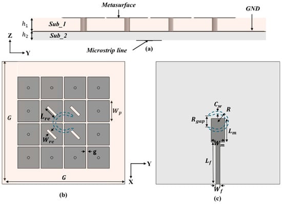
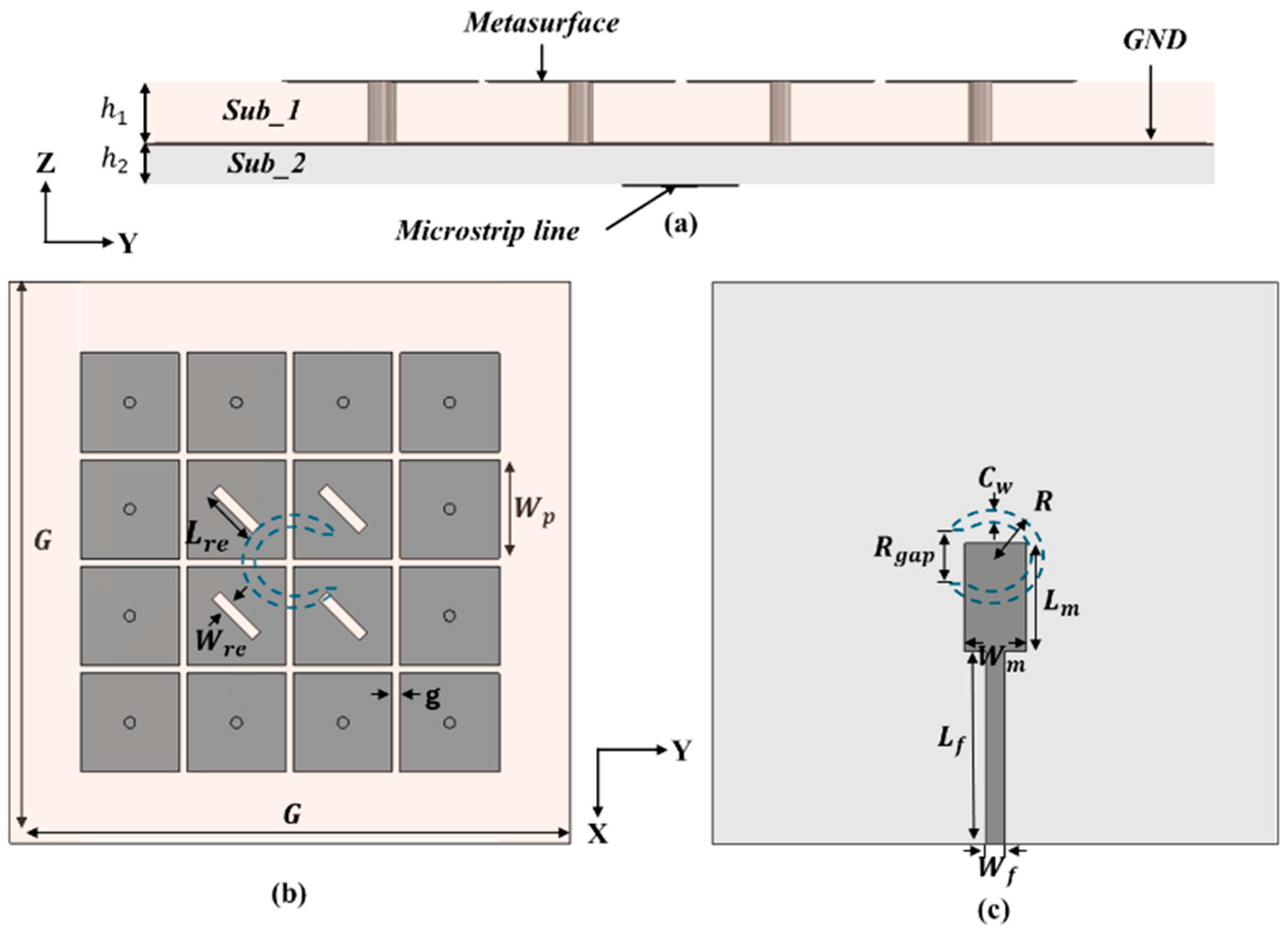
Figure 1 illustrates the configuration of a circularly polarized (CP) metasurface antenna with a 4 × 4 uniform unit cell. In Figure 1a, the antenna consists of three metalized layers, each with a metal thickness of t = 35 m, separated by two substrates. Both substrate materials (RC4003C) have a dielectric constant of = 3.55 and a loss tangent of tan δ = 0.0027 with thicknesses of = 1.524 mm and = 0.813 mm.
Figure 1.
Configuration of the developed CP metasurface antenna. (a) Side view. (b) Top view. (c) Bottom view.
Figure 1b shows the metasurface on the top layer, consisting of 4 × 4 square unit cells with a width () and a gap between adjacent elements equal to (g). The four inner elements 2 × 2 have a rectangular slot with a length of () and a width of (), slanted at 45 degrees. The other twelve elements are made of square patches, each with a shorting via that has a diameter of 0.5 mm. Between the two substrates is a metalized ground plate with a C-shaped slot in the center. The C-shaped slot, which has a radius () and thickness (), features a gap between its open ends equal to () and is used to excite the metasurface layer. In Figure 1c, the bottom metal layer consists of a 50 Ω microstrip line with a width () and length (), connected to a matching stub with a width () and length (). The total antenna structure size is G × G, with a total thickness of 0.056 λ. The antenna is excited using a 50 Ω SMA connector, with the outer conductor connected to the antenna’s ground plane while the inner conductor is connected to the microstrip line. The antenna’s performance was evaluated using Computer Simulation Technology (CST Studio Suite) to achieve broadband impedance matching and circularly polarized radiation, which was subsequently validated through measurements in an anechoic chamber. The final optimized design parameters of the antenna are presented in Table 1.
Table 1.
Dimensions of the proposed antenna.
2.2. Design Process and Operation Principle
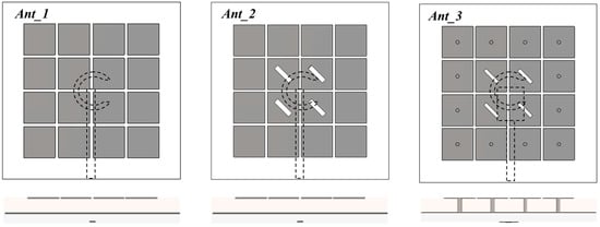
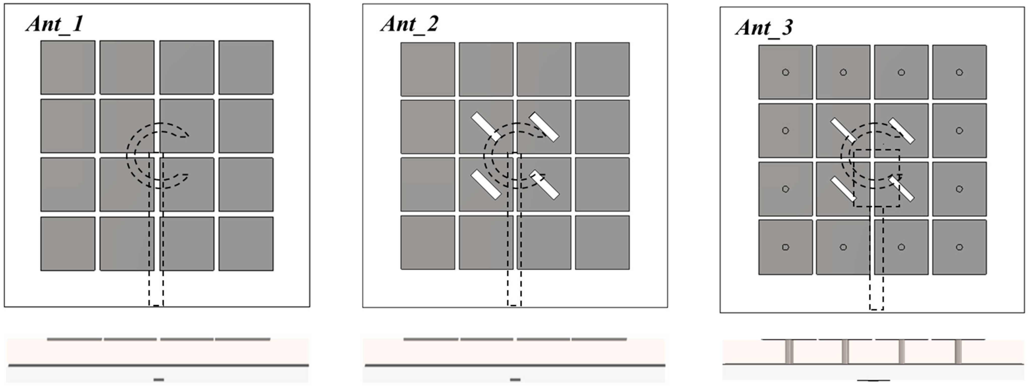
As shown in Figure 2, three antenna designs are compared to clarify the design procedure and operation principles. Ant_1 is the reference antenna, which is a slot antenna fed by a microstrip line integrated with a metasurface layer. The proposed 4 × 4 metasurface antenna can be analyzed using a transmission-line model perspective since the substrate thickness (h ) is much smaller than both the free-space wavelength and the mushroom-array width , as in [24]. The antenna consists of a metasurface layer fed by a microstrip line through a slot on the ground plane. The gaps between unit cells introduce a capacitor-loaded impedance, altering the dispersion characteristics of the composite right-/left-handed (CRLH) structure. The fundamental TM10 mode and the antiphase TM20 mode are excited closely spaced at the right-hand dispersion, leading to a proposed wideband antenna bandwidth and high g. The transmission-line model is still applicable to the mode analysis, and the equations for estimating the dual-mode frequencies are reproduced as follows:
where is the operating frequency, is the speed of light in free space, the extended length, the propagation constant in the extended region, and the propagation constant of the CRLH mushroom unit cell.
Figure 2.
Design process of development CP metasurface antenna, starting from Ant_1, Ant_2, and Ant_3, with the top view and side view for the three steps.
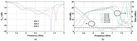
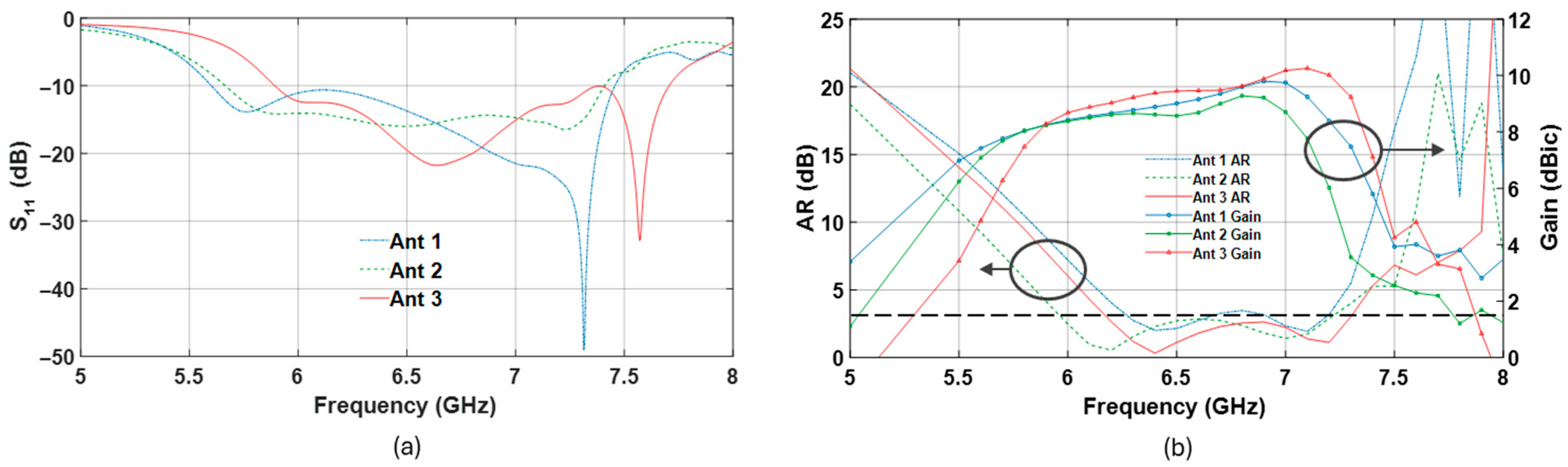
To achieve this, a single microstrip line and a C-shaped slot are used to excite orthogonal modes with a 90° phase difference. So, Ant_1 achieves left-hand circularly polarized (LHCP) radiation with an AR bandwidth of approximately 11%, as shown in Figure 3. However, Ant_1 does not achieve a good AR matching during the full operating bandwidth. By modifying the metasurface layer of the four central elements through the introduction of 45°-inclined rectangular slots, broadband circular polarization is further achieved. As a result, as illustrated in Figure 3, Ant_2 supports wide CP operation, exhibiting left-hand circular polarization (LHCP) with a 3 dB axial-ratio (AR) bandwidth of 16.7%. Furthermore, to enhance the metasurface antenna gain, Ant_3 modifies the twelve elements of the unit cells to be mushroom-shaped. Each element has a shorting via that extends vertically from the center of each unit cell through the substrate to the ground plane. This enhances the antenna gain across the operating bandwidth, with a minimum of 9 dBic to reach a maximum of 10.3 dBic at 7 GHz. Figure 3 summarizes the numerically simulated behavior of the three antenna designs, highlighting their reflection-coefficient bandwidth, axial-ratio bandwidth, and gain performance.
Figure 3.
Comparison of different antennas in Figure 2. (a) (b) AR and Gain.
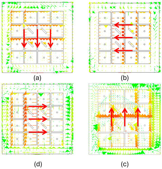
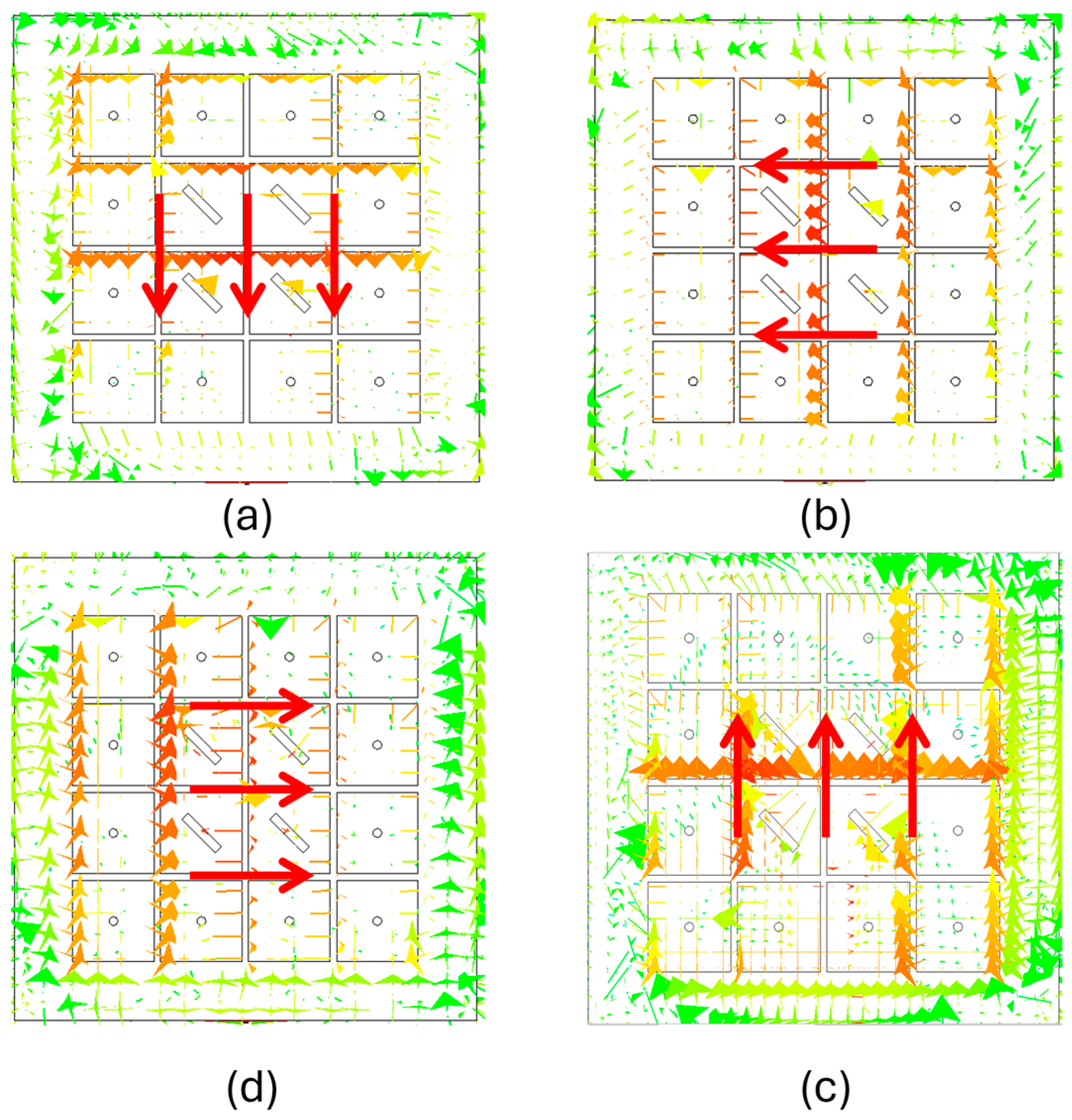
Figure 4 is used to analyze the simulated surface current distribution of the metasurface antenna at various time points in order to demonstrate the operating mechanisms of CP radiation. It is evident that the current distributions are time-dependent and rotate. The current position rotates counterclockwise by changing the time. Therefore, left-handed circularly polarized radiation is generated.
Figure 4.
Surface current distribution at 6.5 GHz (a) 0, (b) T/4, (c) T/2, and (d) 3T/4.
To achieve a wide axial-ratio bandwidth and optimal antenna performance, the C-shaped slot layer must operate within the designated frequency range. Thorough numerical optimization studies of the structural parameters have been performed to obtain more insights. This study analyzes the impact of some critical parameters on antenna performance via systematic numerical simulations, as detailed below.
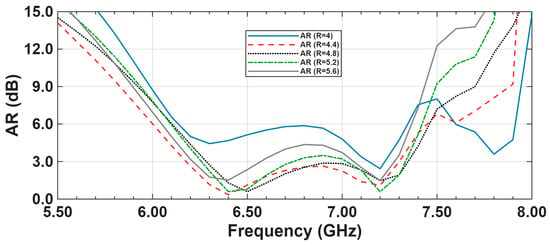
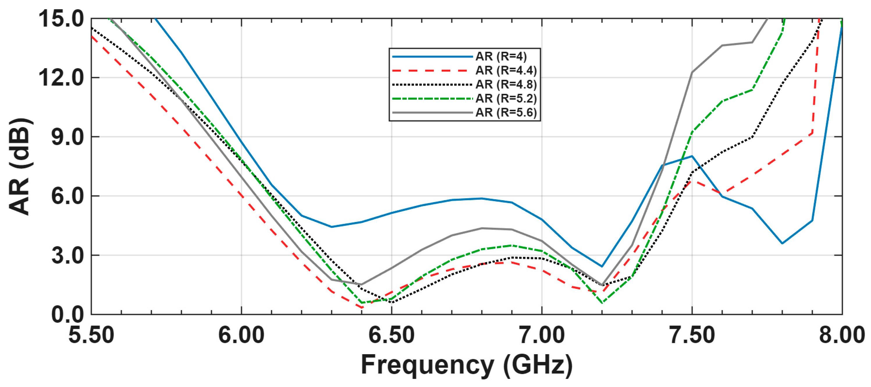
The simulation results show that the axial-ratio (AR) bandwidth is significantly influenced by the C-shaped slot element in the ground layer, indicating that the optimal dimensions of the inner and outer radii of the C-shape, as well as the gap between the open ends of the C-shaped element, are critical in maximizing the circular polarization bandwidth. Analysis of Figure 5 reveals the effect of varying the C-shaped element’s radius (R) on the AR bandwidth while keeping () constant. Within the examined values, the one with R = 4.4 mm exhibits a wide 3 dB AR bandwidth, maintaining AR below 3 dB across the target frequency band for the other radii. Other values, including smaller or larger radii, affect the circular polarization bandwidth. These results confirm that accurate optimization of the C-shaped slot radius is essential for maximizing the circular polarization bandwidth, validating the selected antenna configuration.
Figure 5.
Simulated AR of the antenna with different values for C-shaped element’s radius (R).
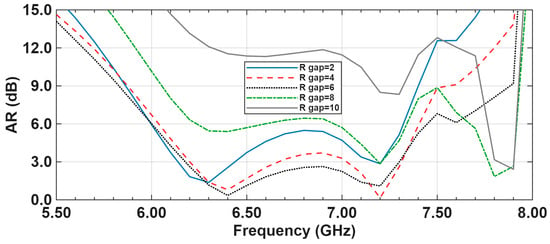
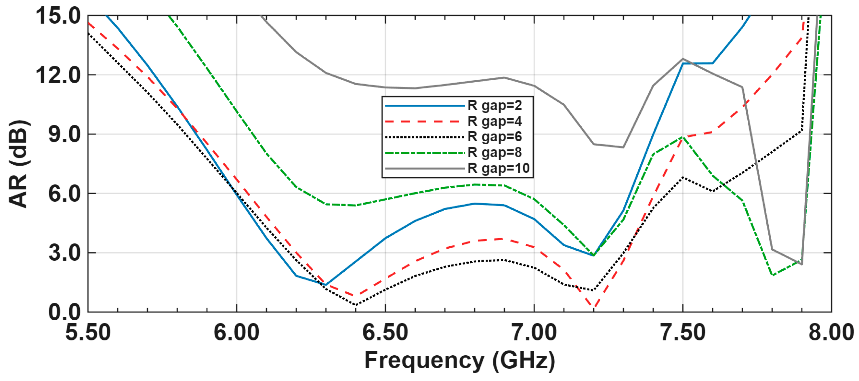
From Figure 6, a clear trend emerges regarding the influence of the C-shaped element’s gap () on the axial-ratio (AR) bandwidth. The results demonstrate that the gap dimension affects the achievable circular-polarization bandwidth. The bandwidth progressively improves as () is increased up to a specific optimal value, beyond which a degradation in AR bandwidth is observed.
Figure 6.
Simulated AR of the antenna with different values of gaps between the open ends of the C-shaped element () size.
3. Results and Analysis
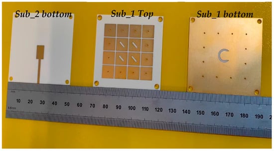
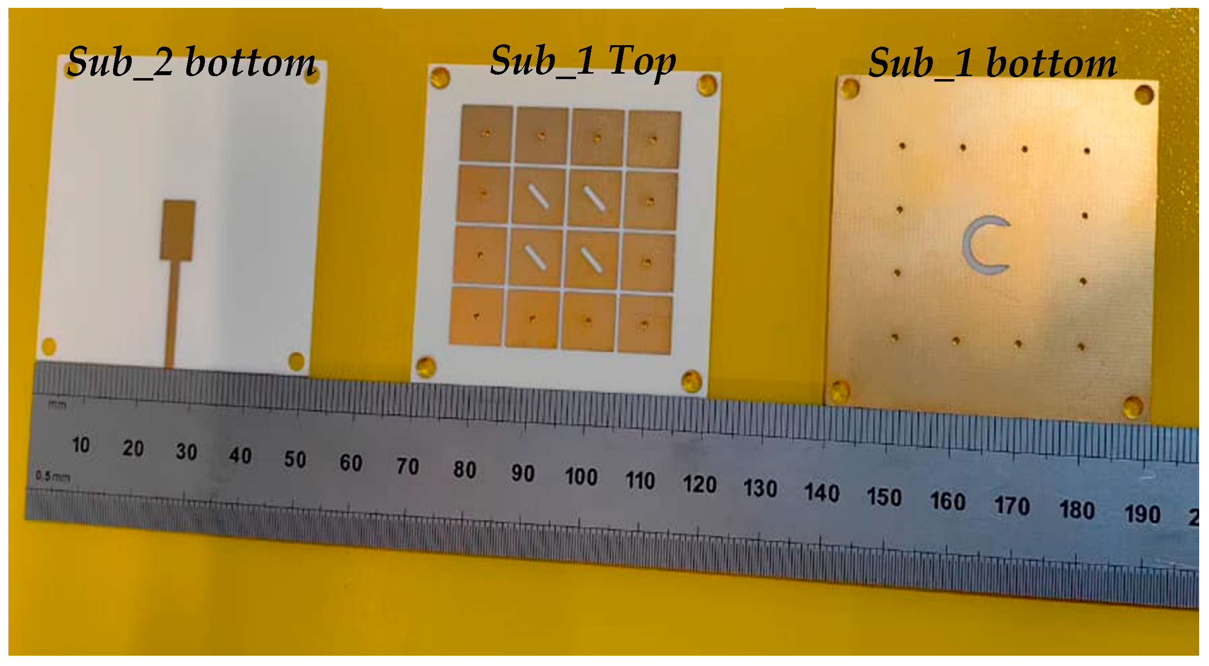
The simulation design was validated by fabricating and testing the prototype of the proposal antenna. The fabricated antenna, depicted in Figure 7, comprises three metallized layers. The metasurface is printed on the top side of Sub_1 Top, while its underside contains a ground plane with a C-shaped slot in Sub_1 bottom. Also, the bottom side of Sub_2 bottom includes the microstrip feedline, and the top side metal of Sub_2 is removed. The proposed manufacturing tolerances are ±150 μm for the slot and ±100 μm for the via drill diameter; it does not affect key antenna characteristics, demonstrating the design’s repeatability and scalability for practical fabrication.
Figure 7.
Prototype of the proposed metasurface antenna.
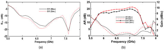
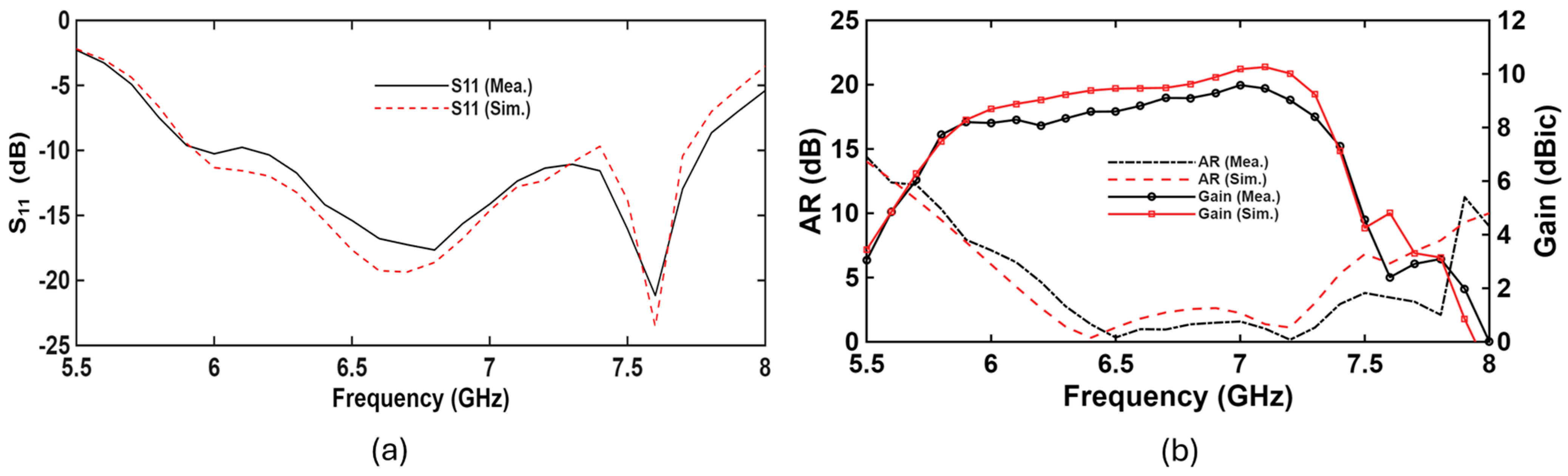
Figure 8a shows the bandwidth of the proposed antenna, including both the simulated and measured results. An observed simulated impedance bandwidth of 26.1% ranged from 5.92 GHz to 7.71 GHz. This is closely aligned with the measured impedance bandwidth of 26.7%, found between 5.91 GHz and 7.75 GHz, confirming the simulation’s accuracy. Figure 8b illustrates the axial-ratio (AR) and gain results at various frequencies. The antenna displayed a simulated axial-ratio (AR) bandwidth of 16.6% from 6.17 GHz to 7.29 GHz, while the experimental measurements indicated an AR bandwidth of 15.7% from 6.28 GHz to 7.35 GHz. Within this operational range, the measured gain consistently exceeded 8 dBic across the band of interest, achieving a maximum gain of 9.6 dBic at 7 GHz.
Figure 8.
Simulated and measured (a) and (b) AR and realized gain values.
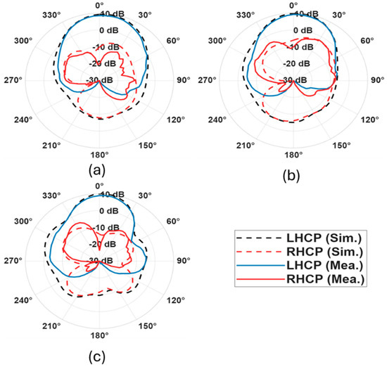
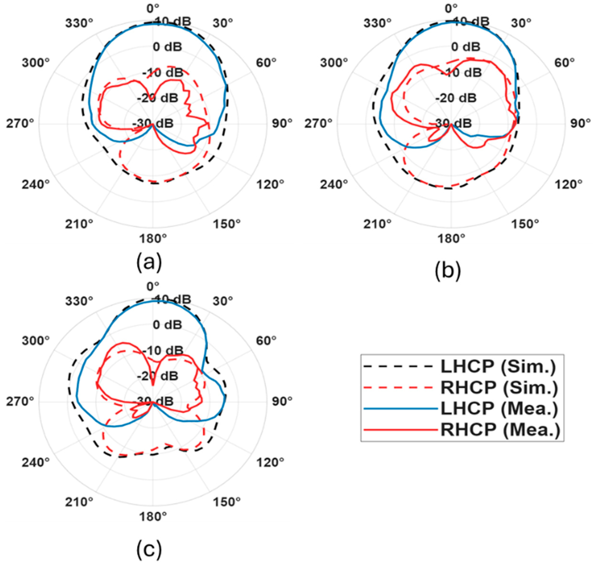
Figure 9 shows the measured and simulated far-field radiation patterns at 6.5 GHz, 6.9 GHz, and 7.2 GHz, respectively. The results show the cross polarization of the three radiation patterns of approximately ≥18–22 dB. Overall, there is good agreement between the simulated and measured results. Moreover, the antenna emits LHCP radiation with a stable pattern. In general, a symmetrical transformation links RHCP and LHCP in CP operation. For the proposed design, LHCP-to-RHCP reconfiguration can be implemented by rotating the central 2 × 2 metasurface by 90° and the C-slot by 180°, each applied in the plane normal to the z-axis.
Figure 9.
Simulated and measured radiation patterns of the proposed CP antenna at (a) 6.5 GHz, (b) 6.9 GHz, and (c) 7.2 GHz.
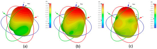
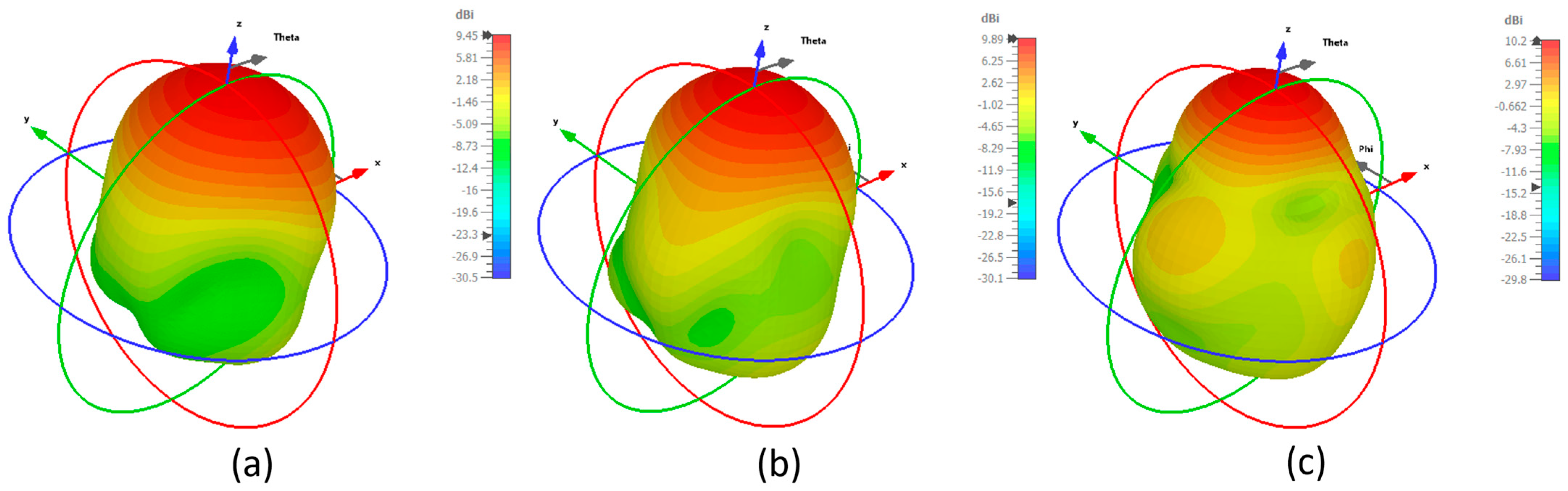
The simulated three-dimensional realized gain radiation patterns of the proposed CP antenna are shown in Figure 10. The antenna has low back radiation, small sidelobes, and stable directional radiation characteristics. Also, the 3D simulated radiation pattern shows a relatively wide main beam (3 dB beamwidth ≈ 50–54°), which is potentially suitable for beam-scanning array solutions because it mitigates gain degradation at moderate scan angles.
Figure 10.
Simulated 3D radiation patterns of the proposed CP antenna at (a) 6.5 GHz, (b) 6.9 GHz, and (c) 7.2 GHz.
Table 2 provides a comprehensive overview of the performance characteristics of various CP 4 × 4 metasurface antennas and compares the proposed antenna in this study with recently documented circularly polarized antennas in the literature, emphasizing the electrical size, operating frequency, impedance bandwidth, axial-ratio bandwidth, and realized gain. In comparison, the proposed antenna achieves a well-balanced performance profile that closely correlates with the objectives of this study. In addition, the proposed design achieves a realized gain of 8–9.6 dBic across the axial-ratio bandwidth, which is significantly higher than that of most comparable works. This demonstrates that the proposed antenna efficiently improves radiation performance while maintaining acceptable impedance and circular polarization bandwidths.
Table 2.
Comparison of the proposed antenna and reference antennas.
4. Conclusions
This study presented a slot antenna integrated with a 4 × 4 metasurface layer for IoT applications and validated its performance through experimental measurements. The results confirm that the proposed circularly polarized antenna achieves improved impedance matching, an extended axial-ratio bandwidth, stable high gain, and high radiation efficiency. Overall, the demonstrated performance indicates that the antenna is a strong candidate for modern wireless IoT communication systems.
Author Contributions
Conceptualization, Y.A., H.V. and T.A.; methodology, Y.A., H.V. and T.A.; software, Y.A.; validation, Y.A., H.V. and T.A.; formal analysis, Y.A., H.V. and T.A.; data curation, Y.A.; writing—original draft preparation, Y.A.; writing—review and editing, H.V. and T.A. All authors have read and agreed to the published version of the manuscript.
Funding
This research received no external funding.
Data Availability Statement
Data is contained within the article.
Acknowledgments
The authors gratefully acknowledge the support provided by Prince Sattam bin Abdulaziz University for the fabrication and measurement facilities.
Conflicts of Interest
The authors declare no conflicts of interest.
References
- Al-Fuqaha, A.; Guizani, M.; Mohammadi, M.; Aledhari, M.; Ayyash, M. Internet of things: A survey on enabling technologies, protocols, and applications. IEEE Commun. Surv. Tutor. 2015, 17, 2347–2376. [Google Scholar] [CrossRef] [Scilit]
- Wang, S.; Chung, K.L.; Kong, F.; Du, L.; Li, K. A simple circularly polarized beam-scanning antenna using modulated slotline-spoof surface plasmon polariton slow-wave transmission line. IEEE Antennas Wirel. Propag. Lett. 2023, 22, 1109–1113. [Google Scholar] [CrossRef] [Scilit]
- Agarwal, K.; Alphones, A. Wideband circularly polarized AMC reflector backed aperture antenna. IEEE Trans. Antennas Propag. 2012, 61, 1456–1461. [Google Scholar] [CrossRef] [Scilit]
- Leung, K. Circularly polarized dielectric resonator antenna excited by a shorted annular slot with a backing cavity. IEEE Trans. Antennas Propag. 2004, 52, 2765–2770. [Google Scholar] [CrossRef]
- Rajanna, P.K.T.; Rudramuni, K.; Kandasamy, K. A high-gain circularly polarized antenna using zero-index metamaterial. IEEE Antennas Wirel. Propag. Lett. 2019, 18, 1129–1133. [Google Scholar] [CrossRef] [Scilit]
- Wang, Z.; Dong, Y.; Itoh, T. Metamaterial-based, miniaturised circularly polarised antennas for RFID application. IET Microw. Antennas Propag. 2021, 15, 547–559. [Google Scholar] [CrossRef] [Scilit]
- Ding, K.; Gao, C.; Qu, D.; Yin, Q. Compact broadband circularly polarized antenna with parasitic patches. IEEE Trans. Antennas Propag. 2017, 65, 4854–4857. [Google Scholar] [CrossRef] [Scilit]
- Ding, K.; Gao, C.; Yu, T.; Qu, D.; Zhang, B. Gain-improved broadband circularly polarized antenna array with parasitic patches. IEEE Antennas Wirel. Propag. Lett. 2016, 16, 1468–1471. [Google Scholar] [CrossRef] [Scilit]
- Alam, M.; Khan, M.; Latif, S. Miniaturization of A Single Feed Dielectric Loaded Wideband High-Gain Circularly Polarized Microstrip Antenna. In Proceedings of the 2023 IEEE International Symposium on Antennas and Propagation and USNC-URSI Radio Science Meeting (USNC-URSI); IEEE: New York, NY, USA, 2023; pp. 193–194. [Google Scholar]
- Kovitz, J.M.; Rahmat-Samii, Y. Using thick substrates and capacitive probe compensation to enhance the bandwidth of traditional CP patch antennas. IEEE Trans. Antennas Propag. 2014, 62, 4970–4979. [Google Scholar] [CrossRef] [Scilit]
- Chen, G.; Lu, Z.; Song, Q. Broadband circularly polarized metasurface antenna based on characteristic mode analysis. In Proceedings of the 2022 3rd International Conference on Intelligent Design (ICID), Xi’an, China, 21–23 October 2022; pp. 129–132. [Google Scholar]
- Sharma, A.; Gangwar, D.; Kanaujia, B.K.; Dwari, S. Gain enhancement and broadband RCS reduction of a circularly polarized aperture-coupled annular-slot antenna using metasurface. J. Comput. Electron. 2018, 17, 1037–1046. [Google Scholar] [CrossRef] [Scilit]
- Liu, S.; Yang, D.; Pan, J. A low-profile circularly polarized metasurface antenna with wide axial-ratio beamwidth. IEEE Antennas Wirel. Propag. Lett. 2019, 18, 1438–1442. [Google Scholar] [CrossRef] [Scilit]
- Liu, S.; Yang, D.; Pan, J. A low-profile broadband dual-circularly-polarized metasurface antenna. IEEE Antennas Wirel. Propag. Lett. 2019, 18, 1395–1399. [Google Scholar] [CrossRef] [Scilit]
- Zhao, C.; Wang, C.-F. Characteristic mode design of wide band circularly polarized patch antenna consisting of H-shaped unit cells. IEEE Access 2018, 6, 25292–25299. [Google Scholar] [CrossRef] [Scilit]
- Dong, J.; Wu, R.; Pan, Y. A low-profile broadband metasurface antenna with polarization conversion based on characteristic mode analysis. Front. Phys. 2022, 10, 860606. [Google Scholar] [CrossRef] [Scilit]
- Huang, Y.; Yang, L.; Li, J.; Wang, Y.; Wen, G. Polarization conversion of metasurface for the application of wide band low-profile circular polarization slot antenna. Appl. Phys. Lett. 2016, 109, 054101. [Google Scholar] [CrossRef] [Scilit]
- Ta, S.X.; Park, I. Low-profile broadband circularly polarized patch antenna using metasurface. IEEE Trans. Antennas Propag. 2015, 63, 5929–5934. [Google Scholar] [CrossRef] [Scilit]
- Le, T.T.; Tran, H.H.; Althuwayb, A.A. Wideband circularly polarized antenna based on a non-uniform metasurface. Appl. Sci. 2020, 10, 8652. [Google Scholar] [CrossRef] [Scilit]
- Naik, D.K.; Panda, D.C.; Swain, R.; Muduli, A.; Nanda, S. Pac-Man Shaped Patch Driven Broadband Circularly Polarized Metasurface Antenna with CMA-Based Quadruple-Mode Excitation. IEEE Access 2025, 13, 13644–13654. [Google Scholar] [CrossRef] [Scilit]
- Supreeyatitikul, N.; Janpangngern, P.; Lertwiriyaprapa, T.; Krairiksh, M.; Phongcharoenpanich, C. CMA-based quadruple-cluster leaf-shaped metasurface-based wideband circularly-polarized stacked-patch antenna array for sub-6 GHz 5G applications. IEEE Access 2023, 11, 14511–14523. [Google Scholar] [CrossRef] [Scilit]
- Juan, Y.; Yang, W.; Che, W. Miniaturized low-profile circularly polarized metasurface antenna using capacitive loading. IEEE Trans. Antennas Propag. 2019, 67, 3527–3532. [Google Scholar] [CrossRef] [Scilit]
- Zheng, B.; Li, N.; Li, X.; Rao, X.; Shan, Y. Miniaturized wideband CP antenna using hybrid embedded metasurface structure. IEEE Access 2022, 10, 120056–120062. [Google Scholar] [CrossRef] [Scilit]
- Liu, W.; Chen, Z.N.; Qing, X. Metamaterial-based low-profile broadband aperture-coupled grid-slotted patch antenna. IEEE Trans. Antennas Propag. 2015, 63, 3325–3329. [Google Scholar] [CrossRef] [Scilit]

Disclaimer/Publisher’s Note: The statements, opinions and data contained in all publications are solely those of the individual author(s) and contributor(s) and not of MDPI and/or the editor(s). MDPI and/or the editor(s) disclaim responsibility for any injury to people or property resulting from any ideas, methods, instructions or products referred to in the content. |
© 2026 by the authors. Licensee MDPI, Basel, Switzerland. This article is an open access article distributed under the terms and conditions of the Creative Commons Attribution (CC BY) license.