


Abstract
The development of autonomous mobile robots or automated guided vehicles is consistently challenged by energy-storage constraints, and while batteries are the standard solution for mobile robots, dynamic wireless power transfer is an alternative way to supply power without reliance on chemical energy storage. For efficient dynamic wireless power transfer, transmitting coils should be energized as required, necessitating real-time position tracking of the receiving coil. Current prevalent techniques require complex modifications to existing systems and additional position sensors, which increase total costs. This article proposes a novel receiving coil position detection method for wireless power transfer systems without using external receiving coil position detection sensors and describes the application of the sensorless coil position detection method and its advantages compared to other methods. The proposed method was implemented on an existing low-power, miniaturized test bench. The described method was successfully validated and correctly switched transmitting coils, ensuring continuous movement of an electric vehicle, therefore proving its viability as a potential new approach for sensorless receiving-coil detection. Experimental results demonstrate that the prototype achieved a maximum power transfer efficiency of 53.8% while maintaining continuous transmitting coil switching operation at vehicle speeds up to 77 cm/s.
1. Introduction
Industrial processes are becoming increasingly automated, and manual human labor is being superseded by various robotic systems and automatization instead. One of the sectors where human labor was prevalent was warehouses. Modern warehouses, to improve service quality, reduce lead times and optimize usage of human resources, are introducing autonomous mobile robots (AMRs) and automating warehouse workflows [1,2].
Developing AMRs or automated guided vehicles (AGVs) always comes with a critical challenge—engineers always face the challenge of supplying power to the device, without attaching it physically to the power source, e.g., with the power cord [3]. Generally, the solution to such a problem is using accumulators or batteries for energy storage, with lithium batteries and charging stations being a prevalent choice in the industry.
A lithium-ion battery comes with its own set of issues, such as limited battery life; during charging, the robot cannot continue to operate, thus not performing useful work and reducing the performance of the warehouse; and with lithium-ion batteries, there are always risks of safety hazards due to their chemistry [4,5].
An alternative and effective way to continuously supply energy to electric vehicles (AMRs, AGVs) without limiting their mobility is to use dynamic wireless power transfer (WPT), thereby significantly reducing the size or eliminating the need for a battery from the design of such electric vehicles [6].
This article focuses on dynamic wireless power transfer (DWPT) systems utilizing inductive-resonant coupling. These systems typically rely on stationary transmitting (primary) coils and receiving (secondary) coils mounted on the AGVs.
WPT systems are widely adopted across various applications and remain a focal point of academic and industrial research. A primary challenge in those systems, as noted in [7], is the precise detection of the receiving coil’s position.
Receiving-coil detection methods may utilize a variety of position-detection sensors, such as optical sensors, magnetoresistive sensors, magnetic sensors, and light-dependent resistors [8,9,10,11]. The primary disadvantage of position detection techniques is the increased cost and complexity of the DWPT system, since additional position-detection sensors and modifications to the system are required. Moreover, optical sensors may interfere with ambient light, whereas magnetic sensors may be affected by stray magnetic fields [12].
To reduce the cost and complexity of the receiving-coil position detection system, several improved solutions have been proposed and experimentally validated in [11] and [12]. These improved position-detection methods are based on a reduced number of position-detection sensors. For example, in [11], the position-detection method utilizes a reduced number of ultrasonic sensors to measure the distance to the electric vehicle. Since ultrasonic sensors do not suffer from magnetic or other types of interference, and the proposed system in [11] employs a reduced number of sensors, this method does not require complex modifications to the system and can be applied to systems with a single inverter and switches used to energize each transmitting coil individually.
To further reduce the cost and complexity of the receiving-coil position detection system, several researchers [7,13,14] have proposed sensorless position-detection methods (i.e., without external position sensors). In [13], a sensorless method for determining the position of the receiving coil mounted on a vehicle is described. The method is based on measurements of the phase angle of the primary resonant tank impedance. When the phase angle of the primary resonant tank i exceeds a predefined threshold, the corresponding transmitting coil i starts transferring power to the receiving coil. Although the position detection system is inexpensive, a disadvantage of this sensorless method is the requirement for a large number of AC sources, namely a high-power and a low-power inverter for each transmitting coil, together with relays. This results in a higher overall DWPT system cost compared with the DWPT system used, for example, in [11] or [12]. The DWPT system with the sensorless solution proposed in [7] also has disadvantages, such as the need for variable-frequency control (which makes compliance with EMC standards more difficult), allowance of only small deviations from a straight trajectory due to the specific structure of multilayer compensation capacitors, and an increased size of the receiving side, since some metal plates of the primary-side compensation capacitor must be attached to the vehicle. The DWPT system without position detection sensors proposed in [14] also suffers from disadvantages, including relatively low overall system efficiency. Furthermore, because many transmitting-side resonant capacitors (one for each transmitting coil) and a long-track coil are required, the overall system cost may not be lower than that of the DWPT system used, for example, in [11].
While DWPT systems traditionally rely on classic position detection solutions utilizing external sensors or alternative methods, as proposed in [7,13,14], both introduce significant hardware complexity and increase total system cost. This article addresses these limitations by proposing a DWPT system with a novel sensorless receiving-coil position detection approach based on maximum inverter input current detection. By utilizing the maximum inverter input current detection, the proposed method eliminates the need for external position sensors. The power stage of the DWPT system is based on a single inverter topology with auxiliary switches to energize each transmitting coil individually, as required, therefore minimizing hardware complexity. Consequently, this approach provides a more cost-effective and robust solution compared to classic position-detection methods and the methods described in [7,13,14].
This article is partly based on a master’s thesis, “Research and Development of Dynamic Resonant-Inductive Wireless Power Transfer System without Position Detection Sensors for Mobile Robots,” defended by D. Lapickis at Riga Technical University in 2025.
2. Materials and Methods
2.1. Description of the Proposed Method for Detecting the Position of the Receiving Coil
Based on findings in [11,12], it can be concluded that, in a system utilizing dynamic inductive-resonant WPT, an electric vehicle equipped with a receiving coil causes changes in the input (inverter) current while moving over an energized transmitting coil.
The peak value of the inverter input current is defined in [11] by expression (1):
where is the peak value of the fundamental component of the inverter output voltage; and are the inductances of the transmitting and receiving coils, respectively; and represent the parasitic resistances of the transmitting-side and receiving-side resonant tanks, respectively; and are the compensation capacitances; is the equivalent load resistance; and is the mutual inductance.
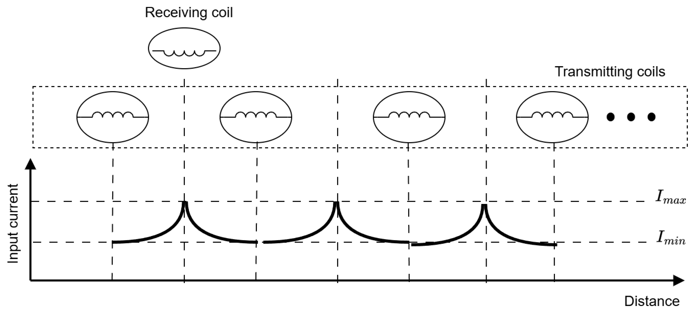
As the receiving coil moves past the transmitting coil, the inductance of the energized primary coil varies due to the misalignment of the transmitting and receiving-coil centers. By tuning the switching frequency to the system’s resonant frequency, specifically at a point where the transmitting coil inductance matches a predefined position, a significant input current spike can be generated. For the purposes of this study, the position for detection (and thus the current maximum) was selected as the midpoint between the centers of two adjacent transmitting coils.
The proposed input current waveform is illustrated in Figure 1. This behavior was validated through multiple experiments on the test bench.
Figure 1.
Illustration of input current changes in the DWPT system relative to the position of the receiving coil to the transmitting coil.
Figure 1 illustrates a significant input current spike (Imax) when the receiving-coil center is positioned above the midpoint of two adjacent transmitting coils. The switching frequency of the WPT system inverter is chosen to be equal to the resonant frequency of the WPT system when the receiving-coil center is located at a distance equal to half the distance between the centers of two adjacent transmitting coils, in order to achieve the maximum input current Imax at that point. This spike is several times higher than both the minimum current value (Imin) and the average current. The described phenomenon can be used to determine the position of the receiving coil and ensure timely switching of the transmitting coils.
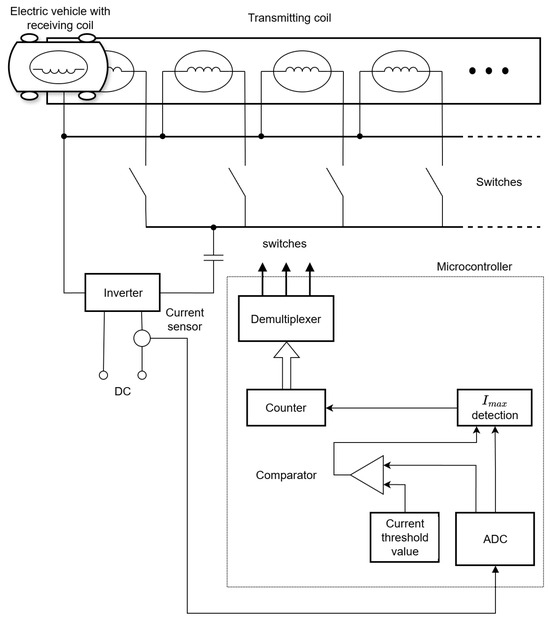
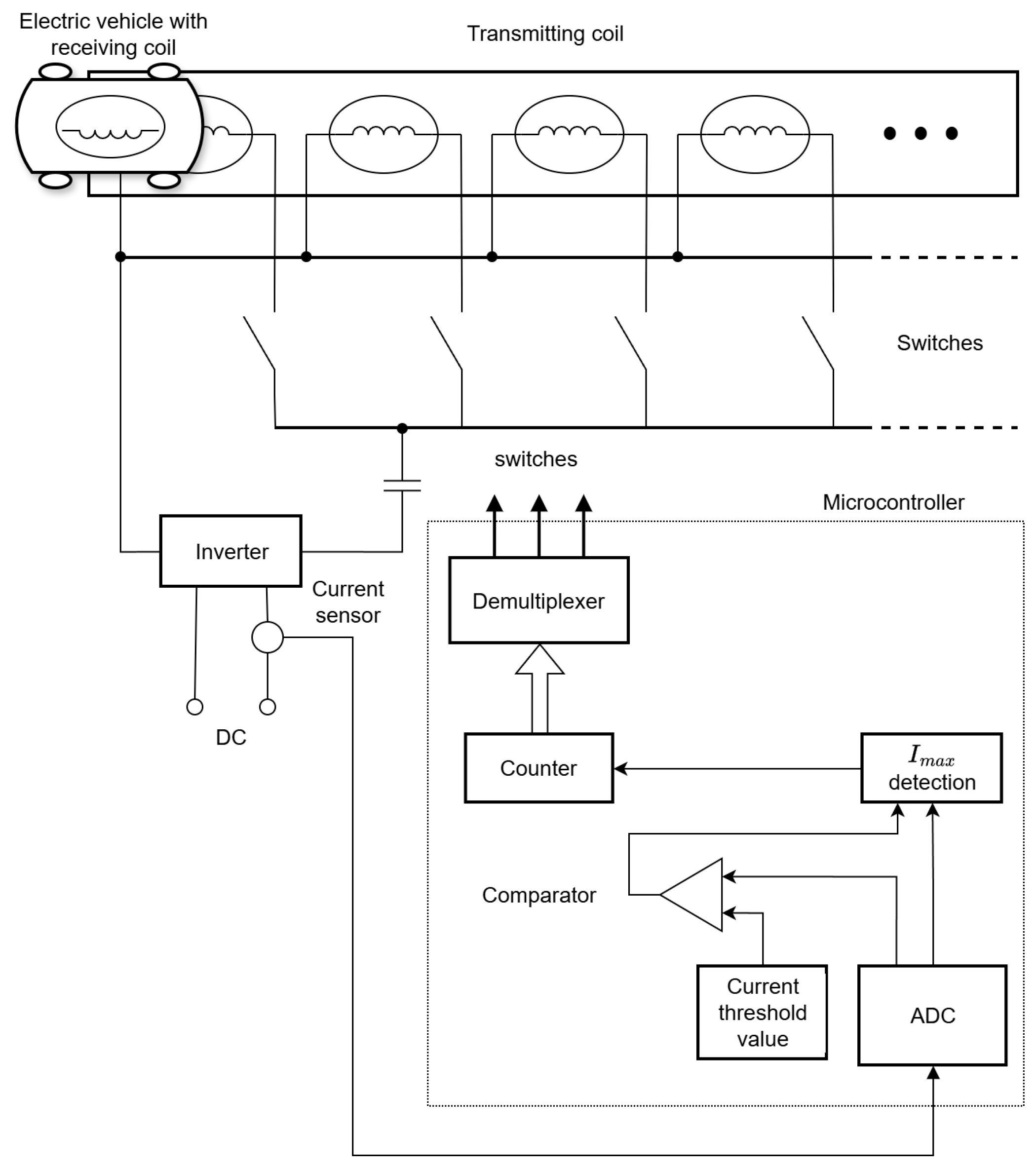
Similar current waveforms were observed in [11], where a combined method was proposed to improve the operation of a high-speed vehicle with a DWPT system using ultrasonic sensors for real-time receiving-coil position tracking. The proposed novel method is an improved iteration of this method that eliminates the need for ultrasonic sensors and is depicted in the block diagram of Figure 2.
Figure 2.
Block diagram of the proposed novel method of receiving coil detection for the DWPT system.
As shown in the block diagram in Figure 2, it is proposed to activate the next transmitting coil when the input current of the currently energized transmitting coil reaches the specified maximum threshold value. The threshold value was determined experimentally, but taking into consideration several orders of magnitude difference between the average current and the current spike during the transition between two transmitting coils, the value need not be extremely precise.
This method does not require complex modifications to the system and uses no external position sensors, relying instead on a single current sensor located at the input and a data-processing device, such as a microcontroller (MC) with an analog-to-digital converter (ADC).
As illustrated in the block diagram in Figure 3, the proposed method is heavily microcontroller-based and operates as follows:
- The MC samples current values from the current sensor and converts them with the ADC;
- Value is compared against a predefined threshold value and simultaneously passed through the Imax detection block;
- If both conditions are met, a counter is incremented, and the demultiplexer switches the currently energized transmitting coil and energizes the subsequent one. This ensures a continuous energy supply to the receiving coil and, consequently, the electric vehicle.
Figure 3.
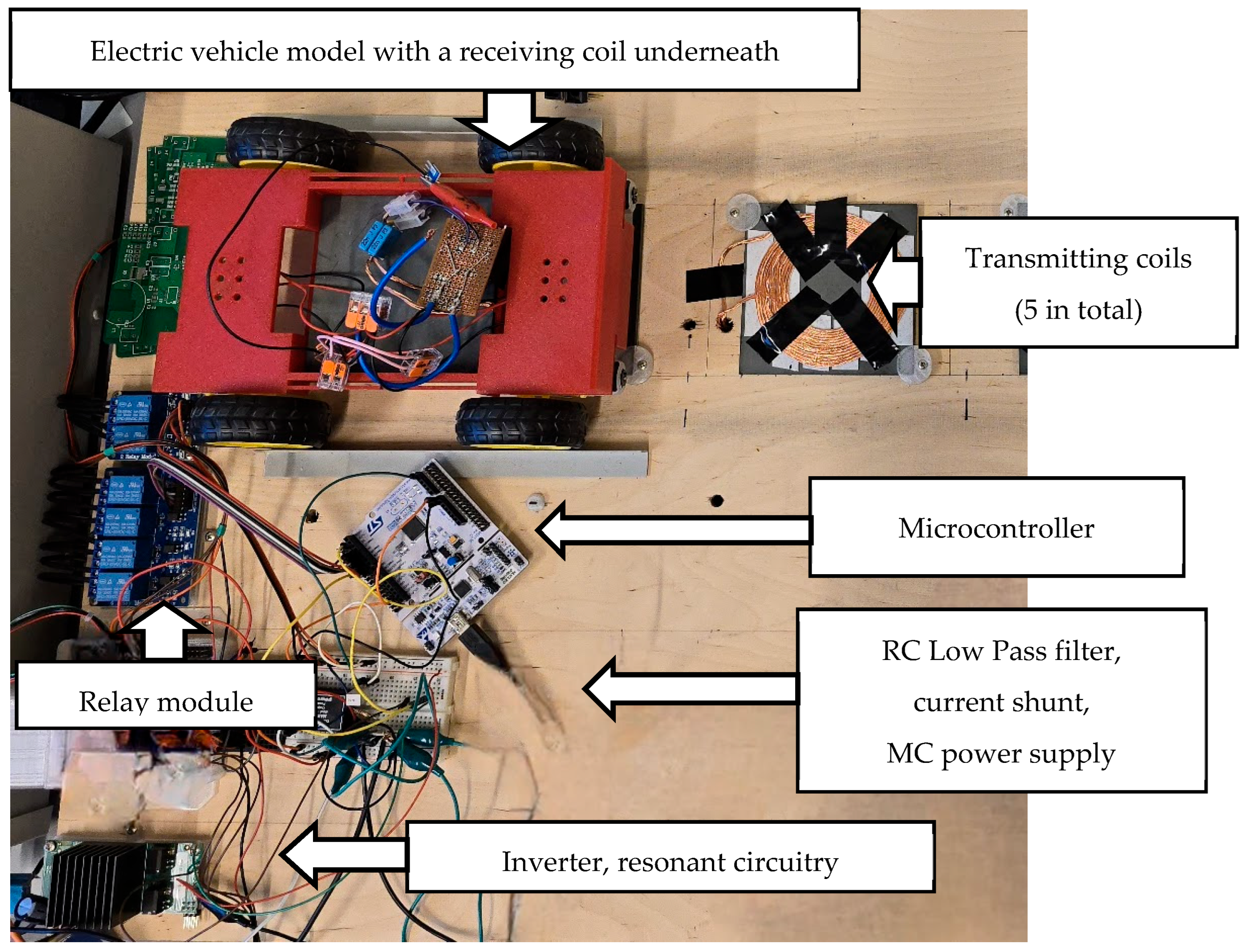
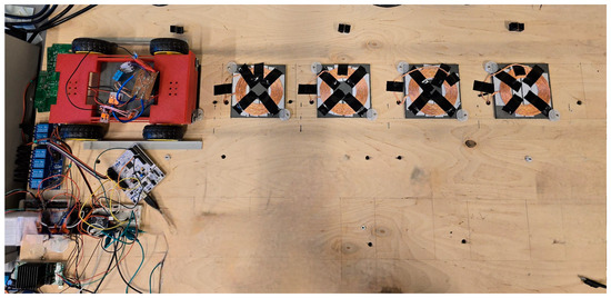
Photograph of a dynamic inductive-resonance WPT test bench with main component labels.
It should be noted that the vehicle does not require any additional input signals to move forward, as the onboard circuit is always switched on. As soon as the transmitting coil transfers power to the receiving coil, the vehicle moves forward.
The proposed method offers the following advantages over existing techniques:
- Reduced hardware complexity: Unlike the approaches in [8,9,10,11,12], which require per-coil or multiple external position sensors, the proposed method relies solely on a single current sensor at the inverter input;
- Cost-effectiveness: The system requires no complex structural modifications, only the addition of a current sensor and microcontroller. In contrast, solutions in [8,9,10,11,12] require multiple sensors, while sensorless alternatives such as [13] require multiple inverters. Furthermore, unlike [7], this method avoids the complexities of variable frequency control, thereby minimizing implementation costs;
- Design simplicity and robustness: The method is noticeably simpler and offers a robust and efficient solution for receiving-coil detection and transmitting coils switching.
However, certain limitations must be acknowledged:
- Algorithm requirement: The effectiveness of the system relies on the development of a precise control algorithm for the timely detection of the receiving coil and correctly switching transmitting coils;
- Efficiency trade-off: The efficiency may be limited due to the inherent nature of the method, as the resonant tuning is not performed at the position of maximum coupling between the transmitting and receiving coils;
- Initial coil-position detection challenge: While the primary scope of this study is to validate the switching logic of the proposed method, initial detection of the receiving-coil position remains a challenge.
2.2. Development of Experimental Prototype
The test bench used to develop an experimental prototype was developed by modifying an existing dynamic inductive-resonance WPT system, which was originally equipped with an ultrasonic sensor and previous modifications [11,12].
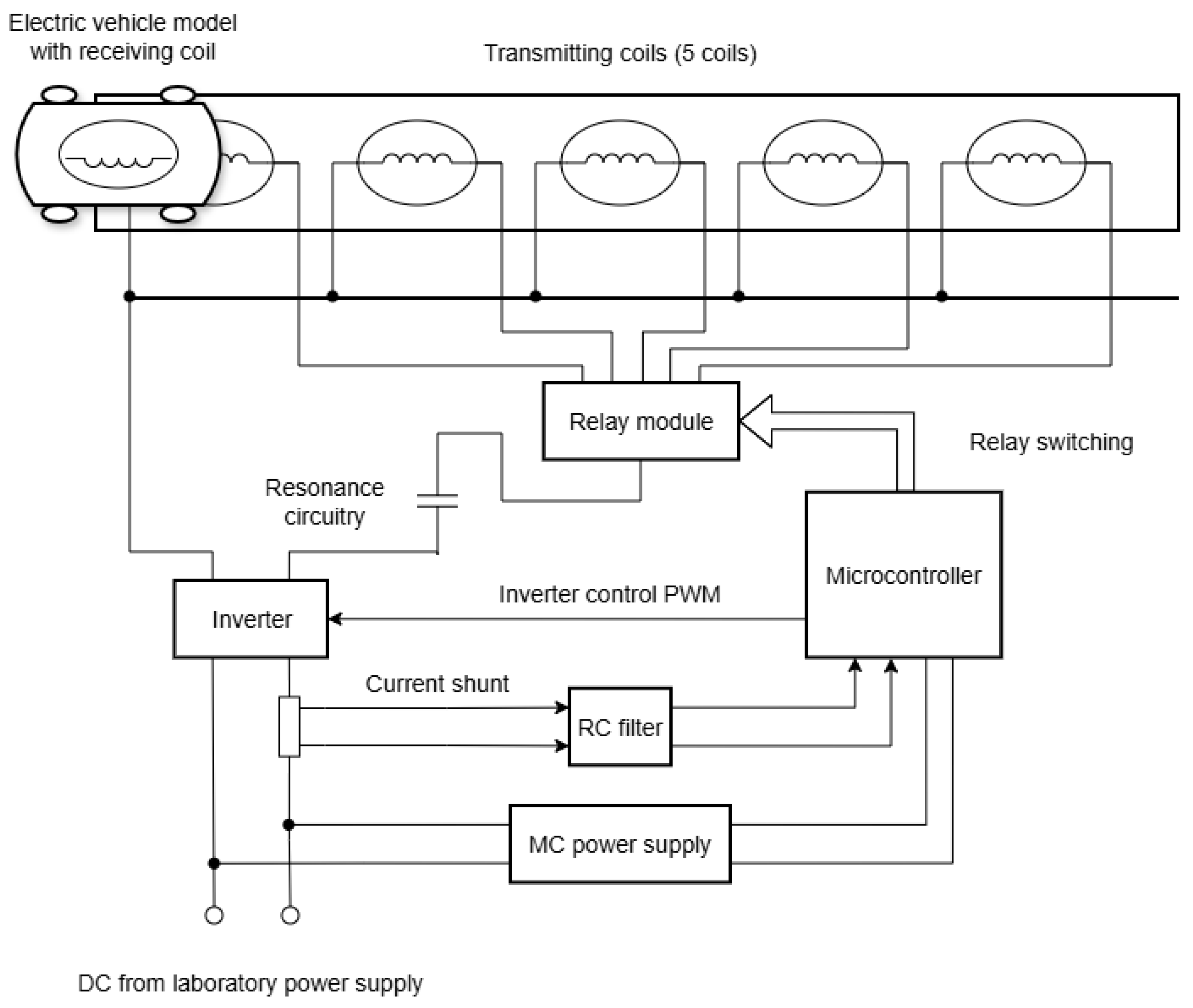
While the electric vehicle model and power electronics components—including inverter, resonance circuitry, and relay module—remained unchanged, the original microcontroller and ultrasonic sensors were removed and replaced with the hardware required for the new method. The modified test bench photograph with the main components labeled is illustrated in Figure 3.
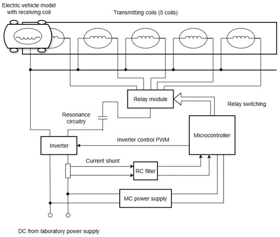
The block diagram of the modified test bench, detailing all major components, is illustrated in Figure 4.
Figure 4.
Illustration of the block diagram of the dynamic inductive-resonance WPT test bench at a glance.
The test bench components can be subdivided into two primary groups: the power electronics group and the control unit group.
The power electronics group consists of:
- A laboratory power supply (0 to 60 V DC);
- A 5 V DC power supply for the microcontroller;
- An inverter with resonance circuitry with a 0.1 Ω shunt resistor for input current sampling;
- A relay module for switching between the five transmitting coils;
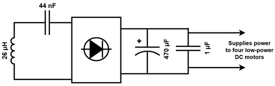
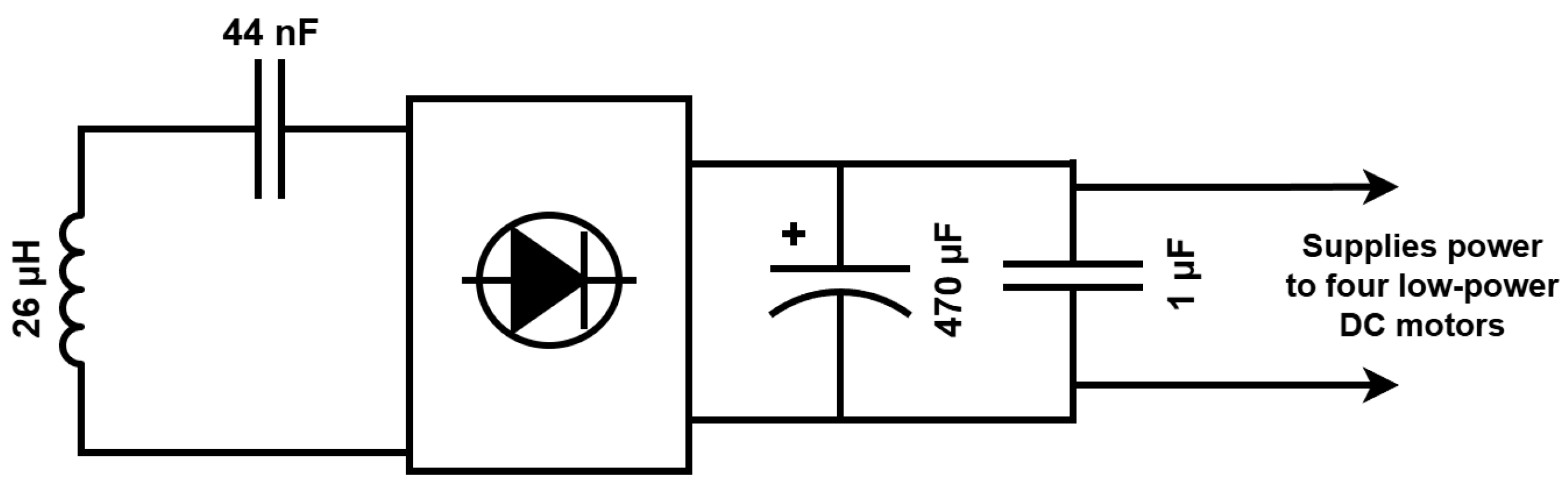
- An electric vehicle model with a bottom-mounted receiving coil, resonance circuitry, a full bridge rectifier, and four low-power DC motors. A simplified schematic of onboard electronics and connections is provided in Figure 5.
Figure 5.
A simplified schematic of the onboard electronics and connections of the electric vehicle model.
The control unit group consists of:
- An STM32 Nucleo-64 STM32F401RE development board;
- A low-pass RC filter connected between the microcontroller’s analog input and the shunt resistor.
The low-pass RC filter was experimentally tuned to minimize electric noise and enhance the reliability and repeatability of current sampling.
The microcontroller performs the following functions:
- Generation of PWM control signal for the inverter;
- Imax detection and transmitting coil switching with a relay module.
The detailed main parameters of the dynamic inductive-resonant WPT system are presented in Table 1.
Table 1.
The main parameters of the dynamic inductive-resonant WPT test bench.
For the proposed method to function effectively, the inverter switching frequency must match the system’s resonance frequency when the receiving coil center is located between the centers of two adjacent transmitting coils. This alignment ensures that the peak input current is achieved at that specific position. Approximate resonance frequency at that point was initially calculated using (2), based on the coil inductance and compensation capacitor values:
However, because the inductance fluctuates due to spatial misalignment, the switching frequency was empirically tuned to ensure the current maximum occurred precisely at the selected detection point.
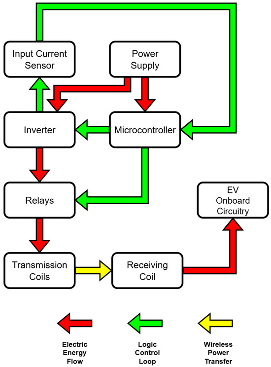
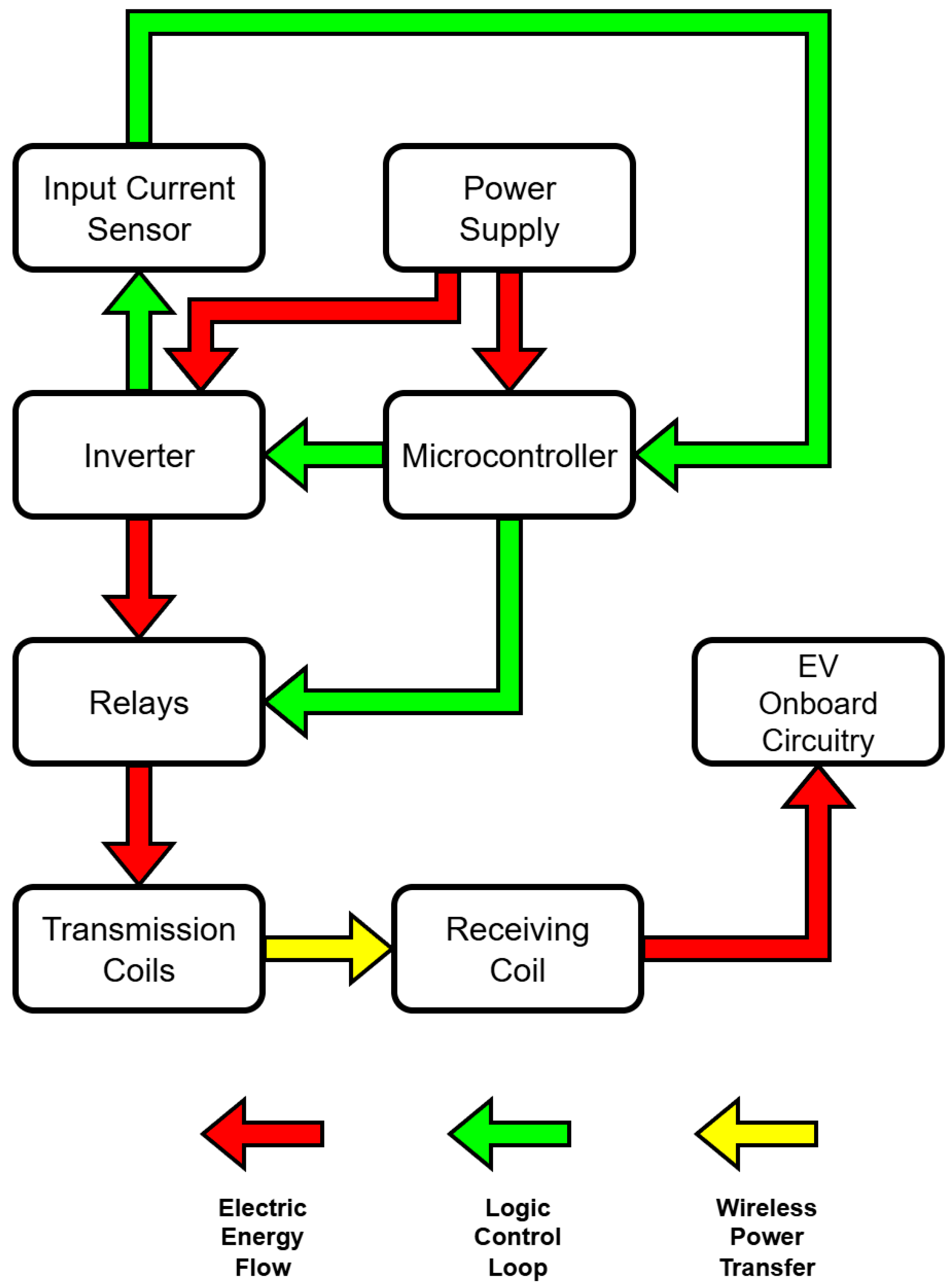
A block diagram of the proposed system showing power flow and control loop is illustrated in Figure 6.
Figure 6.
Block diagram of the DWPT system showing power flow and control loop.
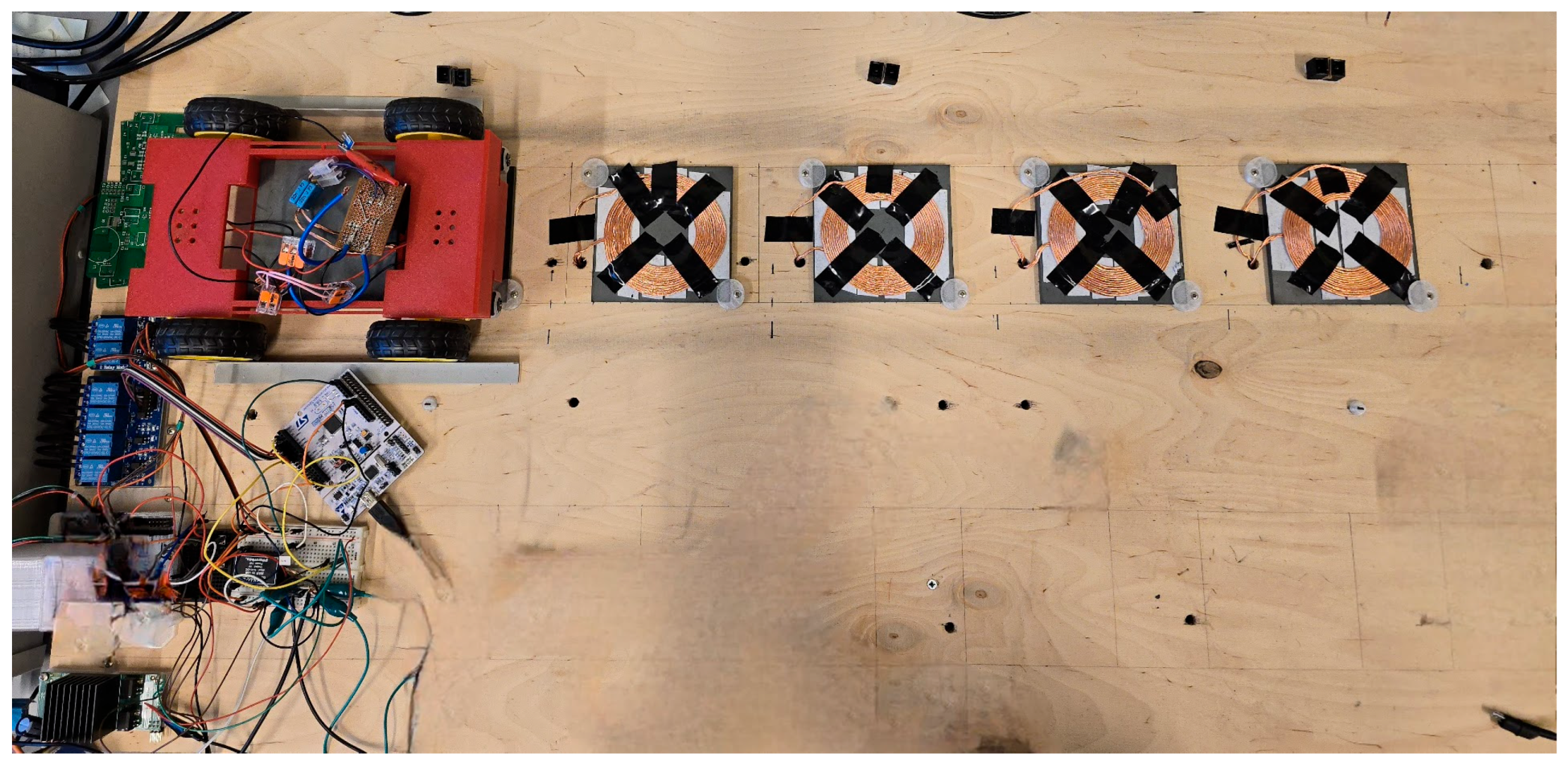
Additionally, the whole test bench is depicted in Figure 7. A single receiving coil, mounted on the bottom of the vehicle, is positioned coplanar with the stationary transmitting coils.
Figure 7.
Photograph of the whole test bench, with all five transmitting coils present.
2.3. New Method Implementation with Microcontroller’s Algorithm and Program
The control device, the microcontroller, is central to the system’s operation. From the previous subsection, it can be concluded that the implementation of the correct algorithm and code is one of the essential stages of system design.
The STM32 Nucleo-64 development board, featuring the STM32F401RE microcontroller, was selected for its ease of use, the comprehensive integrated development environment (IDE) STM32CubeIDE, and its ability to meet all technical requirements for the proposed detection method.
The requirements for the microcontroller were defined as follows:
- At least one ADC and an analog input;
- Programmable digital outputs;
- A programmable hardware timer capable of generating PWM and inverted PWM signals with dead-time setting;
- Comprehensive manufacturer and community support, documentation.
The flow chart of the microcontroller program algorithm is shown in Figure 7.
The primary variables are defined as follows:
- i—an integer variable that acts as a counter and stores the index of the currently energized coil from 0 to 4, representing the five transmitting coils, respectively;
- voltage_threshold—a floating-point constant that stores the voltage threshold value for the current spike Imax;
- shunt_voltage—a floating-point variable that stores the current shunt voltage drop calculated from the ADC values;
- elapsed_time, elapsed_time_old, start_time—variables used to calculate the duration between two occurred Imax detections.
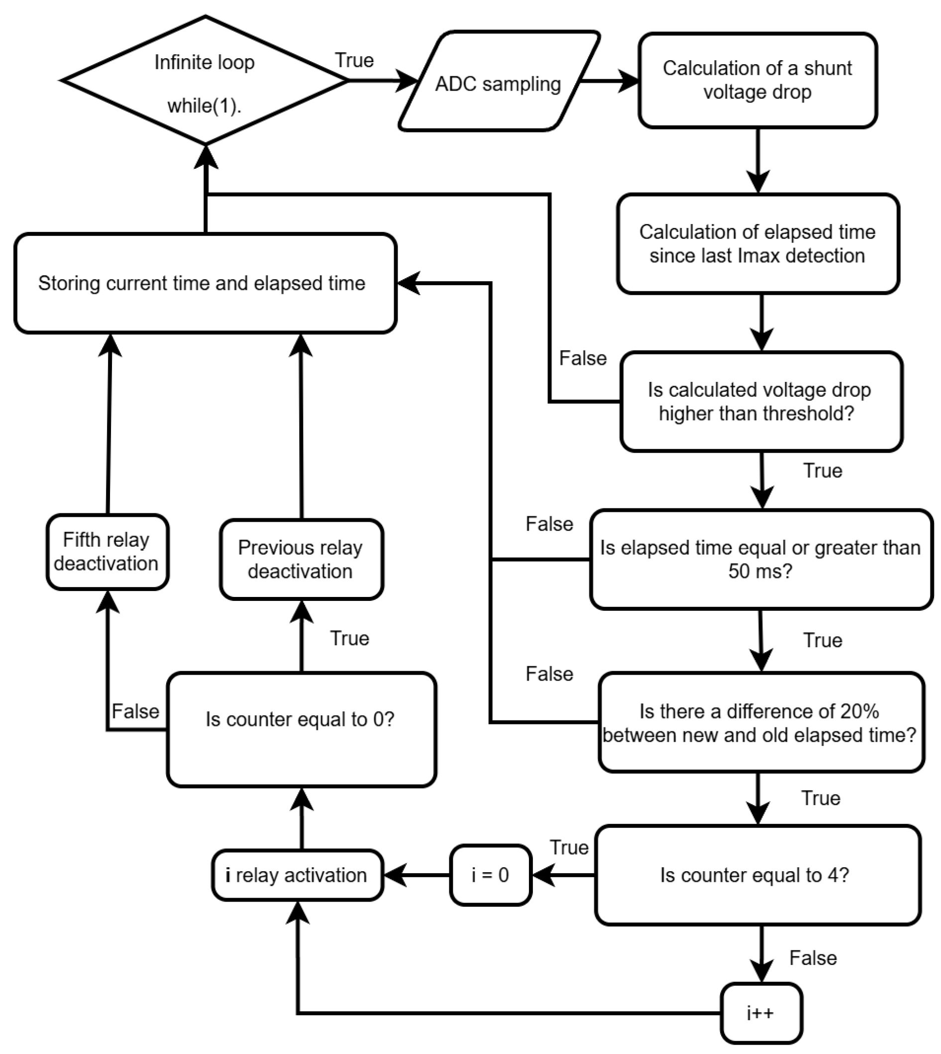
As shown in Figure 8, the algorithm identifies the optimal switching moment based on two specific criteria within the main loop:
- Voltage threshold—if the shunt voltage exceeds the threshold value, then the Imax current spike at the inverter input has been reached;
- Duration between two detections—the elapsed time between two subsequent Imax detections. If the calculated duration is below a predetermined threshold, the detection is ignored to prevent false switching.
Figure 8.
Flow chart of the main microcontroller program.
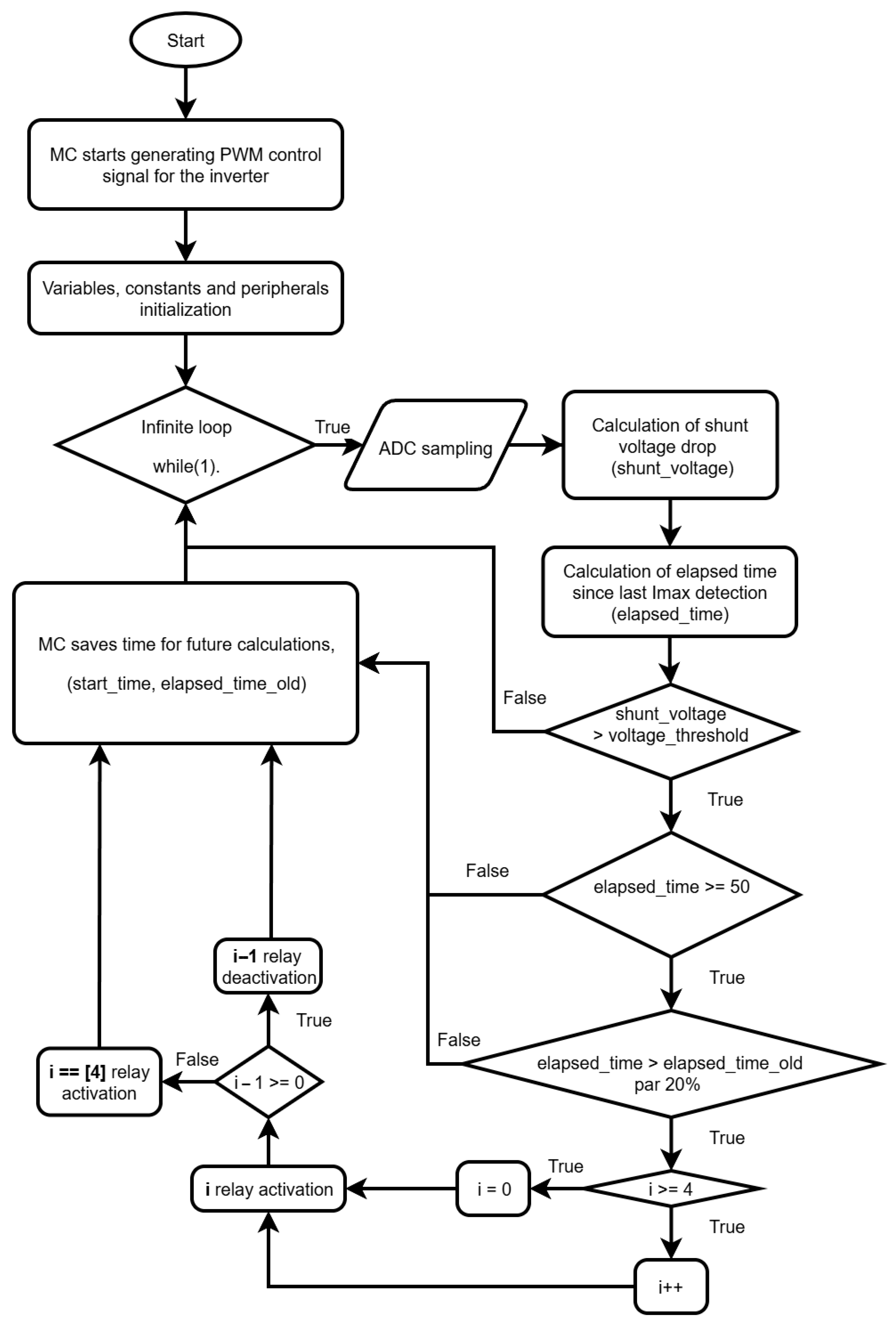
The voltage threshold is derived from the inverter input current value, and it is compared against the voltage drop across the shunt resistor. In this test bench configuration, every 1 A of input current corresponds to a 0.1 V drop across the series-connected shunt resistor. Experimental debugging revealed that the Imax current spike was several times higher than the average current, typically reaching approximately 6 A. Consequently, the voltage threshold was established as 0.6 V, corresponding to the voltage drop across the shunt resistor.
2.4. Microcontroller Current Spike Imax Detection and Transmitting Coil Switching Code
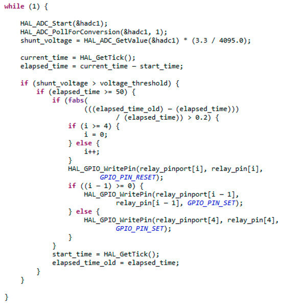
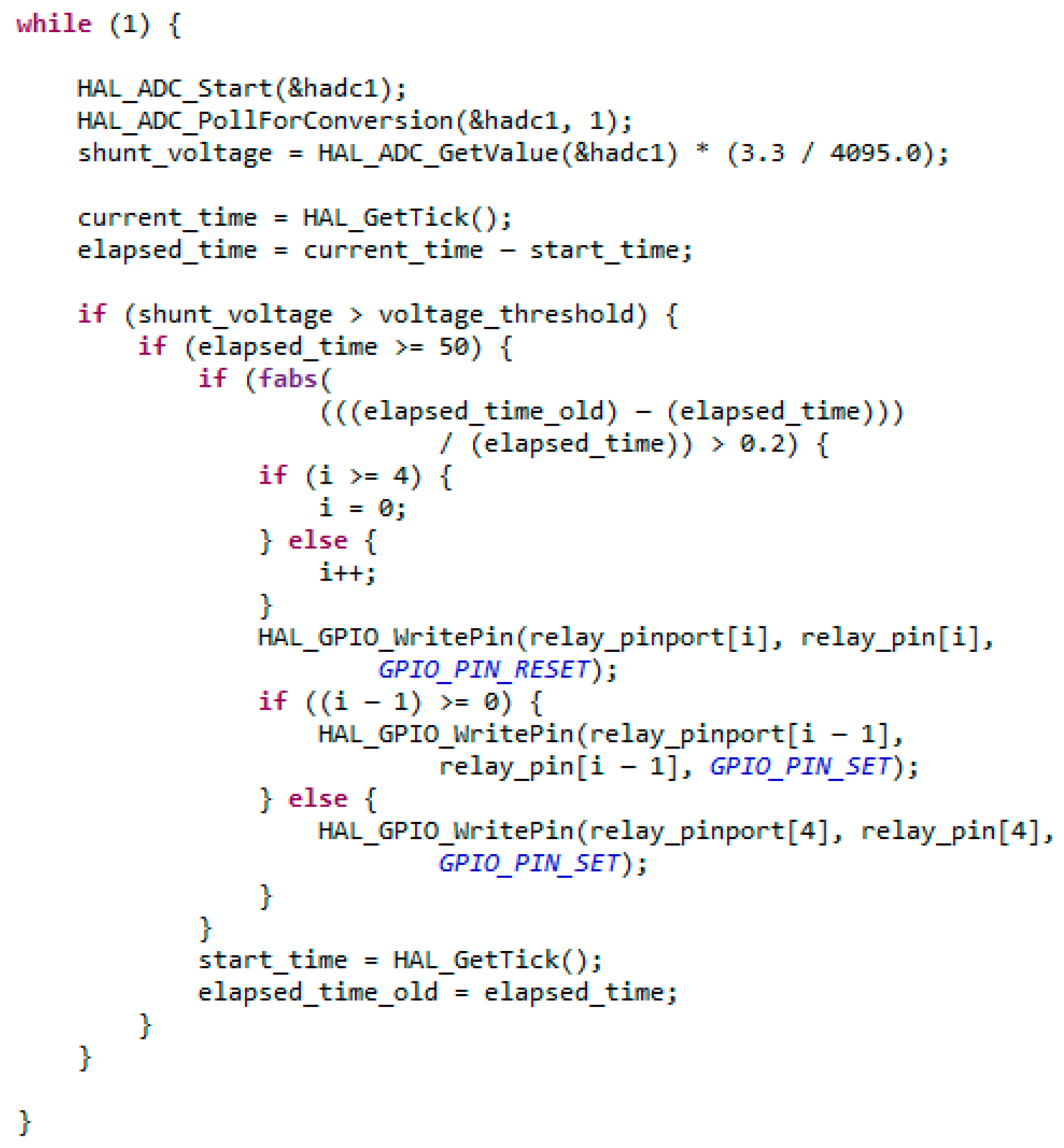
Microcontroller was programmed using STM32CubeIDE and C programming language. The snippet of the main microcontroller loop with Imax detection is provided in Figure 9.
Figure 9.
Snippet of the main microcontroller loop written in C.
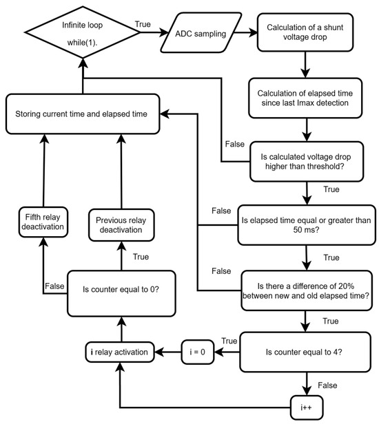
The snippet of code in Figure 9 is illustrated as a diagram in Figure 10 for better reader understanding.
Figure 10.
Diagram graphically illustrating code from Figure 9.
2.5. Experimental Testing Plan
Following the modification and debugging of the test bench, the proposed method was experimentally validated.
Two experiments were conducted to test the method targeting two electric vehicle speeds—45 cm/s and 75 cm/s— for results to be comparable to [12].
The experiment procedure was as follows:
- The electric vehicle model was placed at the starting position on the first transmitting coil for each trial;
- Four synchronized waveforms were recorded using a single 4-channel oscilloscope: input voltage and current of the inverter, and the output voltage and current from the onboard rectifier;
- To achieve the target speeds of the electric vehicle model, the laboratory power supply voltage was adjusted accordingly.
During the test bench debugging phase, the switching frequency was adjusted from 149 kHz to 142 kHz. This adjustment was made to align the current spike with the specific position where the receiving coil is centered at the midpoint between two adjacent transmitting coils.
3. Results
3.1. First Experiment
The target speed for the first experiment was defined as 45 cm/s.
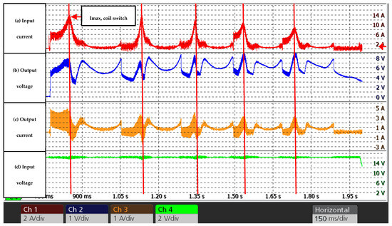
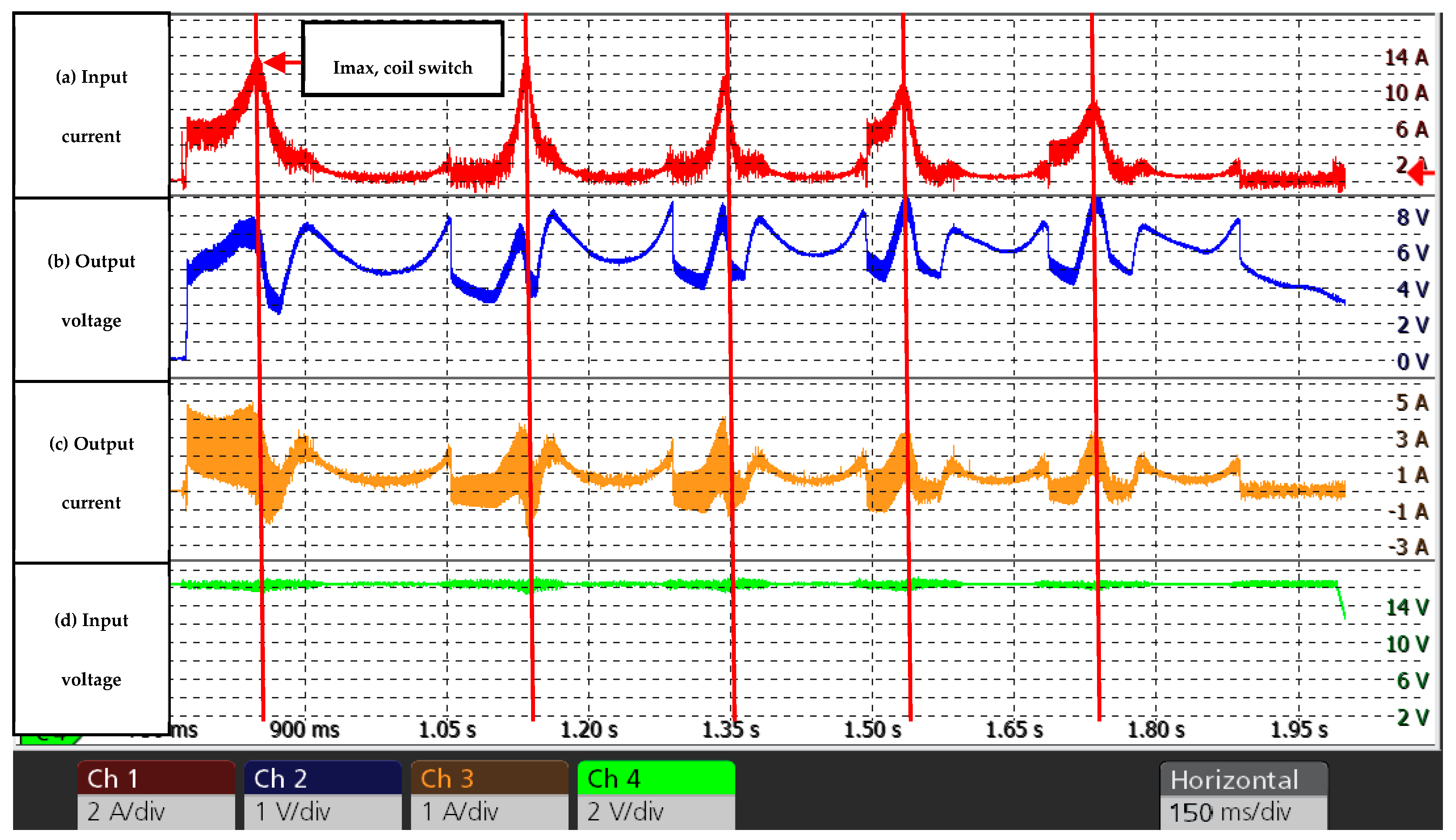
The four synchronized waveforms were obtained, which are shown in Figure 11:
- (a)
- Inverter input current;
- (b)
- Rectifier output voltage on the electric vehicle;
- (c)
- Rectifier output current on the electric vehicle;
- (d)
- Inverter input voltage—while this remained largely constant, its waveform was recorded to simplify the data processing.
Figure 11.
Experimentally obtained waveforms: (a) inverter input current; (b) output voltage of the WPT system; (c) output current of the WPT system; (d) inverter input voltage. The vehicle speed is 49 cm/s.
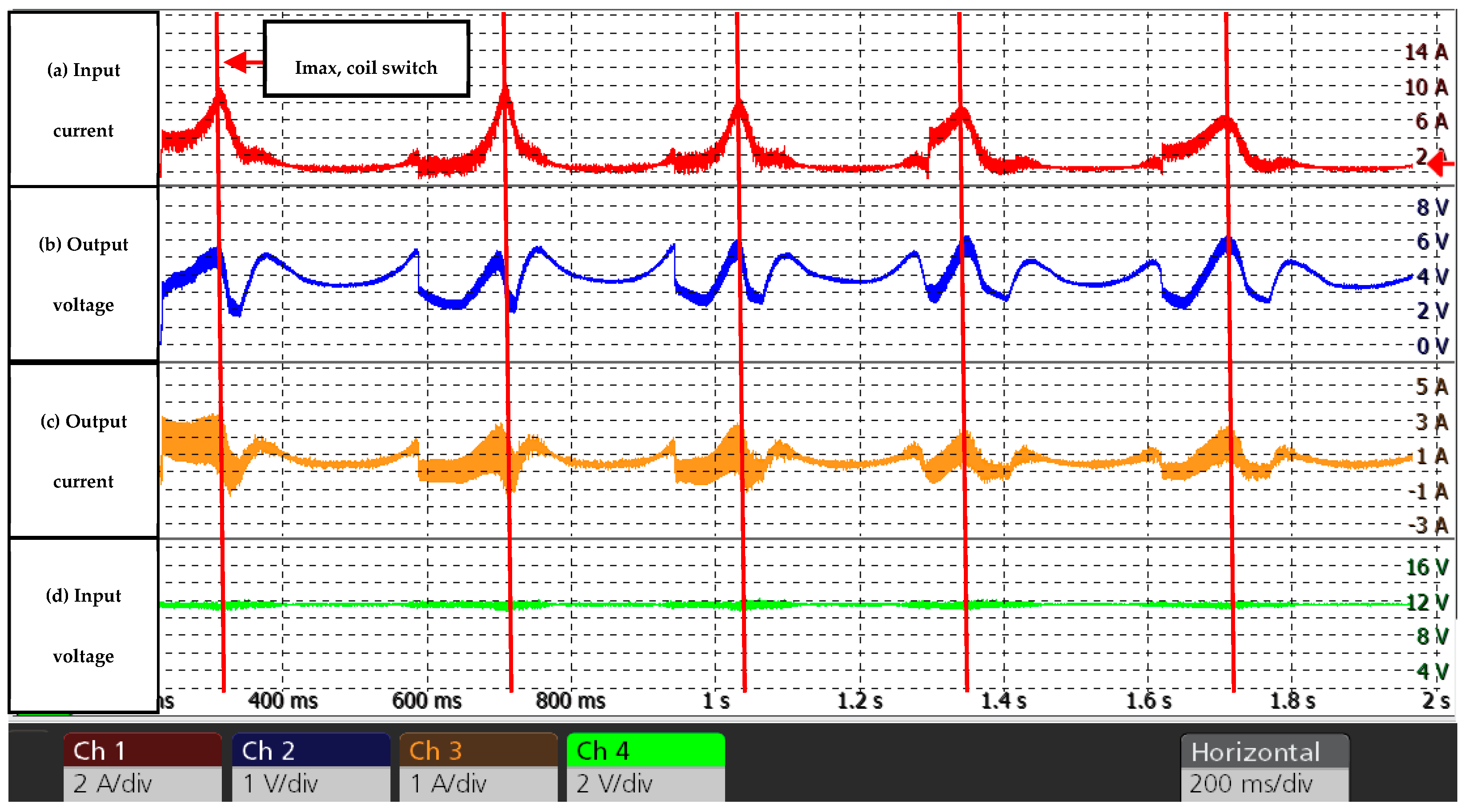
The input current maximum (Imax) and consequently the transmitting coils switching instants are marked with red vertical bars.
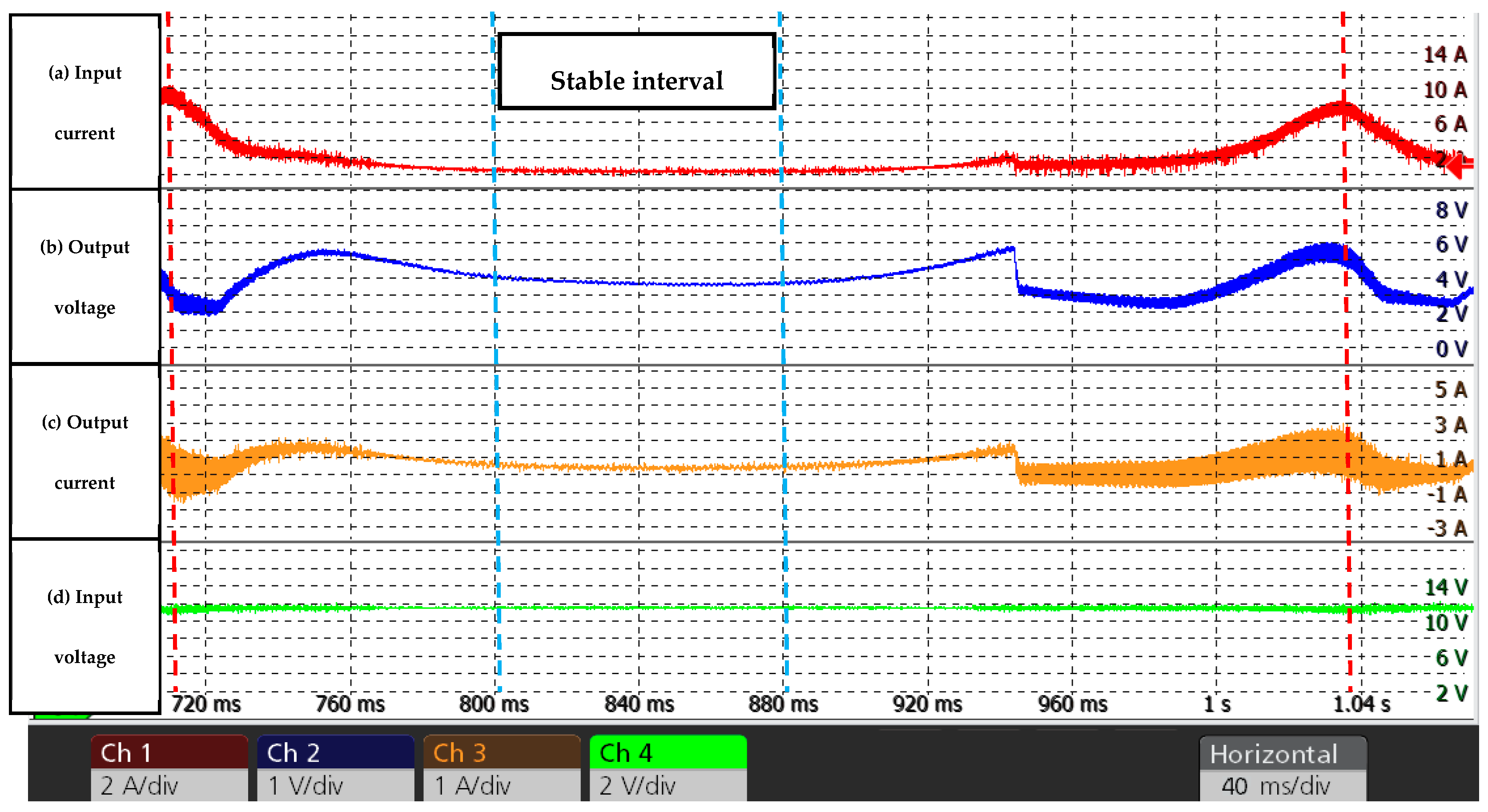
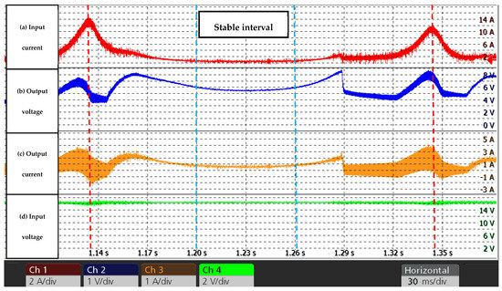
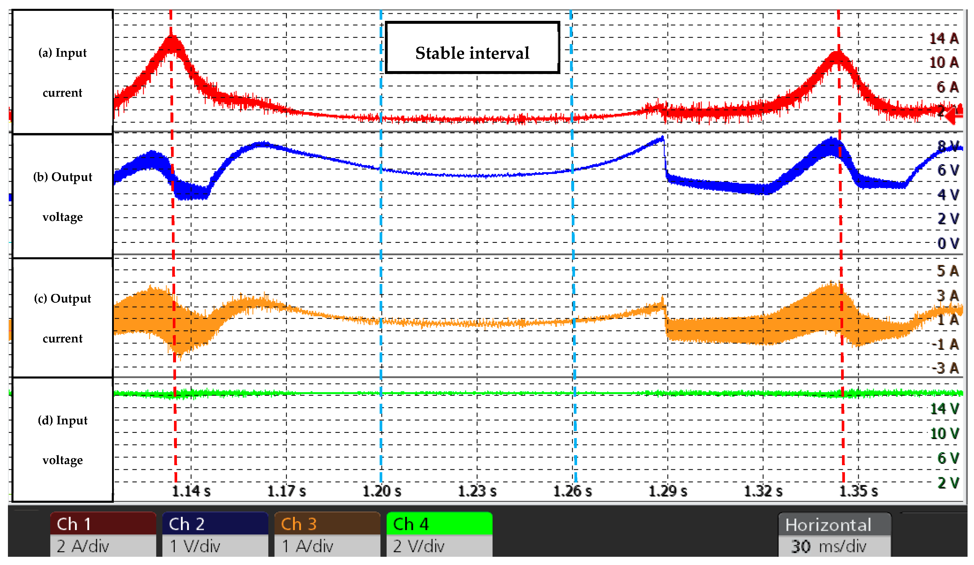
The period between consecutive input current peaks was analyzed using experimentally obtained waveforms. These waveforms are illustrated in Figure 12. A stable time interval is indicated by blue vertical dotted lines.
Figure 12.
Experimental waveforms: (a) inverter input current; (b) output voltage of the WPT system; (c) output current of the WPT system; (d) inverter input voltage. The vehicle speed is 49 cm/s. Note: the waveforms are shown over one period.
The vehicle speed and system efficiency were calculated using the built-in oscilloscope tools.
Given that the distance between coil centers is 16 cm and the current peaks at the midpoint between two adjacent transmitting coils, the time interval between peaks was used to determine the actual speed.
In the first experiment, the calculated vehicle speed was ≈ 49 cm/s, which is acceptably close to the target speed.
Two efficiency coefficients were evaluated:
- Peak-to-Peak efficiency was calculated as the ratio of average output power (≈2.8 W) to average input power (≈18 W) during the period between current peaks (indicated by red vertical dotted lines in Figure 12). This coefficient was ≈ 15.5%.
- Stable interval efficiency was calculated as the ratio of average output power (≈1.5 W) to average input power (≈3.2 W) during the period in a stable time interval, indicated by blue vertical dotted lines in Figure 12. This coefficient was ≈ 46.8%.
3.2. Second Experiment
The target speed for the second experiment was defined as 75 cm/s. The experiment was performed similarly to the first experiment, but the input voltage was increased to achieve a higher speed.
The four synchronized waveforms were obtained, which are shown in Figure 13:
Figure 13.
Experimentally obtained waveforms: (a) inverter input current; (b) output voltage of the WPT system; (c) output current of the WPT system; (d) inverter input voltage. The vehicle speed is 77 cm/s.
Similarly, the period between consecutive input current peaks was analyzed using experimentally obtained waveforms, as depicted in Figure 14.
Figure 14.
Experimental waveforms: (a) inverter input current; (b) output voltage of the WPT system; (c) output current of the WPT system; (d) inverter input voltage. The vehicle speed is 77 cm/s. Note: the waveforms are shown over one period.
Based on calculations, the vehicle speed in the second experiment was ≈ 77 cm/s, which is close to the target speed.
Two efficiency coefficients were evaluated in a manner similar to the first experiment:
- Peak-to-Peak efficiency coefficient was ≈ 17.4%.
- Stable interval efficiency coefficient was ≈ 53.2%.
4. Discussion
The experiments were successfully completed, and the proposed method worked as planned: the transmitting coils were switched at the correct timing, and the vehicle movement was stable and uniform. The waveforms were visually similar to those obtained in previous studies; however, the efficiency coefficient was significantly lower than, for example, in [12]. This outcome suggests underlying issues in the modified system and the test bench.
On the other hand, it is worth noting that the inverter’s operating frequency was significantly altered to implement the proposed method (147 kHz in [12] versus 142 kHz in this article), which is a possible reason for the lower efficiency of dynamic wireless power transfer.
The observed reduction in efficiency may be attributed to interconnection losses and parasitic impedances resulting from the experimental wiring. Additionally, the inclusion of shunt resistors in series with the resonant circuitry introduced further losses. These factors likely contributed to an increased resistance at contact points and shifted the resonant frequency, thereby further degrading overall system performance.
Although maximizing power transfer efficiency was not the primary objective of this research, the coil topology employed is a limiting factor for dynamic wireless power transfer (DWPT). Studies [15,16,17,18] have demonstrated that circular coils, such as the one used here, are suboptimal for dynamic applications due to their low misalignment tolerance. In contrast, the Double-D (DD) coil topology offers superior misalignment tolerance and could significantly enhance the overall efficiency of the proposed system.
An additional issue identified from the experiments is the challenge of determining the receiving-coil starting position. While this did not pose serious issues for the current test bench function, it could become problematic on longer test tracks or with faster vehicle speeds.
A potential method for determining the starting or initial position of the receiving coil, while utilizing existing hardware, is to “scan” transmitting coils utilizing low current. The proposed procedure is based on the following concepts:
- Sequential excitation: Since the microcontroller regulates which transmitting coil is energized at any given time, the system can sequentially energize each coil while monitoring current variations;
- Current regulation: By modulating the inverter’s switching frequency and PWM signal duty cycle, the microcontroller can restrict the current to a level sufficient for detection but below the threshold required to drive the EV motors, ensuring the vehicle remains stationary during the scan;
- Pattern recognition: A detection algorithm must be developed to recognize current changes;
- Position detection: By “scanning” all the transmitting coils, the specific coil coupled with the receiving coil can be determined to establish the initial position.
Future research directions would be:
- Improving the electrical part of the test bench (e.g., securing connections, minimizing parasitic capacitances, and inductances);
- Investigating the test bench and system for other potential issues that affect efficiency;
- Exploring methods for determining the starting position of the receiving coil with and without additional sensors;
- Improving the software (code) to simplify experimental trials.
5. Conclusions
The method described was successfully validated. The modified test bench correctly switched the transmitting coils, ensuring continuous movement of an electric vehicle model, thus proving the viability of the proposed method as a potential new approach for sensorless receiving-coil detection.
By eliminating the need for external position sensors, the proposed method significantly reduces the hardware complexity and total cost of ownership for DWPT systems in smart logistics.
However, both the test bench and the method require further research and refinement to be utilized in industrial environments.
Author Contributions
Conceptualization, D.S. and D.L.; methodology, D.L.; software, D.L.; validation, D.S. and D.L.; formal analysis, D.L.; investigation, D.L.; resources, J.Z.; data curation, D.L.; writing—original draft preparation, D.L.; writing—review and editing, D.S.; visualization, J.Z.; supervision, D.S.; project administration, J.Z.; funding acquisition, J.Z. All authors have read and agreed to the published version of the manuscript.
Funding
This research was funded by the Riga Technical University, grant number ZM-2025/6.
Data Availability Statement
The data presented in this article are available on request from the corresponding author due to privacy concerns.
Conflicts of Interest
The authors declare no conflicts of interest. The funders had no role in the design of the study; in the collection, analyses, or interpretation of data; in the writing of the manuscript; or in the decision to publish the results.
References
- Mejri, E.; Kelouwani, S.; Dube, Y.; Henao, N.; Agbossou, K. Energy Efficient Order Picking Routing for a Pick Support Automated Guided Vehicle (Ps-AGV). IEEE Access 2022, 10, 108832–108847. [Google Scholar] [CrossRef] [Scilit]
- Majid, S.A.A.; Zakaria, W.N.W.; Patar, M.N.A.A.; Tomari, M.R.M.; Amari, M.D.; Kasran, F.A.M. Optimized Global Path Planning with SLAM for Efficient Warehouse Autonomous Mobile Robot. In Proceedings of the 2025 IEEE 6th International Conference in Robotics and Manufacturing Automation (ROMA), Selangor, Malaysia, 20–22 August 2025; Institute of Electrical and Electronics Engineers Inc.: New York, NY, USA, 2025; pp. 377–381. [Google Scholar]
- Shinohara, N. Wireless Power Transfer via Radiowaves; ISTE-Wiley: Hoboken, NJ, USA, 2014; ISBN 9781118862964. [Google Scholar]
- Chen, W.; Han, X.; Pan, Y.; Yuan, Y.; Kong, X.; Liu, L.; Sun, Y.; Shen, W.; Xiong, R. Defects in Lithium-Ion Batteries: From Origins to Safety Risks. Green Energy Intell. Transp. 2025, 4, 100235. [Google Scholar] [CrossRef] [Scilit]
- McNulty, D.; Hennessy, A.; Li, M.; Armstrong, E.; Ryan, K.M. A Review of Li-Ion Batteries for Autonomous Mobile Robots: Perspectives and Outlook for the Future. J. Power Sources 2022, 545, 231943. [Google Scholar] [CrossRef] [Scilit]
- Patil, D.; Miller, J.M.; Fahimi, B.; Balsara, P.T.; Galigekere, V. A Coil Detection System for Dynamic Wireless Charging of Electric Vehicle. IEEE Trans. Transp. Electrif. 2019, 5, 988–1003. [Google Scholar] [CrossRef] [Scilit]
- Pakhaliuk, B.; Husev, O.; Shevchenko, V.; Kroics, K.; Stepins, D.; Strzelecki, R. Automatic Position Detection and Transmitting Activation of Dynamic Wireless Power Transfer System with Air Capacitor. In Proceedings of the 2022 Wireless Power Week (WPW), Bordeaux, France, 5–8 July 2022; IEEE: Hoboken, NJ, USA, 2022; pp. 487–491. [Google Scholar]
- Liang, C.; Zhang, Y.; Li, Z.; Yuan, F.; Yang, G.; Song, K. Coil Positioning for Wireless Power Transfer System of Automatic Guided Vehicle Based on Magnetic Sensing. Sensors 2020, 20, 5304. [Google Scholar] [CrossRef] [Scilit] [PubMed]
- Jeebklum, P.; Kirawanich, P.; Sumpavakup, C. Dynamic Wireless Power Transfer with a Resonant Frequency for Light Duty Electric Vehicle. Int. J. Intell. Eng. Syst. 2021, 14, 417–426. [Google Scholar] [CrossRef] [Scilit]
- Thalapil Vaheeda, J.; George, B. TMR Sensor-Based Detection of EVs in Semi-Dynamic Traffic for Optimal Charging. IEEE Trans. Intell. Transp. Syst. 2022, 23, 13721–13730. [Google Scholar] [CrossRef] [Scilit]
- Stepins, D.; Zakis, J.; Sokolovs, A.; Husev, O.; Strzelecki, R.; Doncker, R.W. de Dynamic Wireless Power Transfer System for Indoor AGV With a Distance-Measurement-Based Position Detection Technique. IEEE Access 2025, 13, 71551–71562. [Google Scholar] [CrossRef] [Scilit]
- Stepins, D.; Sokolovs, A.; Zakis, J. Dynamic Resonant-Inductive Wireless Power Transfer System for Automated Guided Vehicles with Reduced Number of Position Sensors. Electronics 2024, 13, 2377. [Google Scholar] [CrossRef] [Scilit]
- Xiong, W.; Liu, J.; Chen, J.; Hu, D. Detection of Secondary Side Position for Segmented Dynamic Wireless Charging Systems Based on Primary Phase Angle Sensing. Electronics 2023, 12, 2148. [Google Scholar] [CrossRef] [Scilit]
- Matsumoto, H.; Noborikawa, R.; Zaitsu, T.; Shibako, Y. Wireless Power Transfer System With Passive Boost Topology for AGVs. IEEE Open J. Ind. Appl. 2020, 1, 227–235. [Google Scholar] [CrossRef] [Scilit]
- Lammle, T.; Parspour, N.; Holz, J. Comparison of Circular and Double-D Coil Topologies for Automotive Inductive Charging Systems. In Proceedings of the 2020 IEEE PELS Workshop on Emerging Technologies: Wireless Power Transfer (WoW), Seoul, Republic of Korea, 15–19 November 2020; IEEE: Hoboken, NJ, USA, 2020; pp. 68–73. [Google Scholar]
- Mohammad, M.; Choi, S. Optimization of Ferrite Core to Reduce the Core Loss in Double-D Pad of Wireless Charging System for Electric Vehicles. In Proceedings of the 2018 IEEE Applied Power Electronics Conference and Exposition (APEC), San Antonio, TX, USA, 4–8 March 2018; IEEE: Hoboken, NJ, USA, 2018; pp. 1350–1356. [Google Scholar]
- Xiang, L.; Sun, Y.; Tang, C.; Dai, X.; Jiang, C. Design of Crossed DD Coil for Dynamic Wireless Charging of Electric Vehicles. In Proceedings of the 2017 IEEE PELS Workshop on Emerging Technologies: Wireless Power Transfer (WoW), Chongqing, China, 20–22 May 2017; IEEE: Hoboken, NJ, USA, 2017; pp. 1–5. [Google Scholar]
- ElGhanam, E.; Hassan, M.; Osman, A.; Kabalan, H. Design and Performance Analysis of Misalignment Tolerant Charging Coils for Wireless Electric Vehicle Charging Systems. World Electr. Veh. J. 2021, 12, 89. [Google Scholar] [CrossRef] [Scilit]


Disclaimer/Publisher’s Note: The statements, opinions and data contained in all publications are solely those of the individual author(s) and contributor(s) and not of MDPI and/or the editor(s). MDPI and/or the editor(s) disclaim responsibility for any injury to people or property resulting from any ideas, methods, instructions or products referred to in the content. |
© 2026 by the authors. Licensee MDPI, Basel, Switzerland. This article is an open access article distributed under the terms and conditions of the Creative Commons Attribution (CC BY) license.