


Abstract
Large-scale grid integration of renewable generation is facilitated by resource abundance and advancements in power electronics. The high penetration of power electronics-based devices reduces system inertia, threatening grid stability. The Virtual Synchronous Generator (VSG) provides an effective solution. However, when the grid is unbalanced, problems such as unbalanced output current, overcurrent, and power fluctuations occur. Thus, a VSG power–current collaborative control strategy based on improved second-order generalized integrator (SOGI) is proposed. Firstly, the generation of power fluctuation and unbalanced current in VSG output under an unbalanced power grid is analyzed. Secondly, to suppress the DC component and high-order harmonics, an improved SOGI method is proposed for positive and negative sequence separation by introducing a difference node and adding an extra SOGI module on the basis of the traditional SOGI. To achieve the collaborative control of active/reactive power constant and current balance, a correlation coefficient μ is introduced and a unified equation is constructed. To prevent overcurrent during fault, virtual impedance and reactive power reference are introduced. Simulations have verified the effectiveness of the proposed method. It shows superiority in effective sequence separation, smooth power–current collaborative control, and safe operation without overcurrent.
1. Introduction
With the scheme of a “Double Carbon” goal and the construction of a new type of power system, renewable generation, primarily wind turbine and photovoltaic, has undergone rapid development [1]. However, with the increasing penetration of renewable generation, the security and stability of power systems face a huge threat. By emulating the operational mechanism of synchronous generators, Virtual Synchronous Generator (VSG) technology endows grid-connected inverters with virtual inertia and damping, thereby effectively enhancing system stability [2]. However, on account of asymmetric line parameters or asymmetric faults, unbalanced faults occur. This will lead to the imbalance of the grid-connected current and double-frequency oscillation of VSG output power. It seriously affects power quality and system stability [3]. To suppress power oscillation and balance output current, it is essential to study the VSG control strategy under an unbalanced grid.
Studies have been conducted to improve control strategies. In the studies on positive–negative sequence separation methods, reference [4] used notch filter for positive and negative sequence separation and reference current calculation. It achieved current balance. However, notch filter is sensitive to voltage unbalance and has transient overshoot. Reference [5] used dual second-order generalized integrator (DSOGI) to realize fast and effective sequence separation of Vienna rectifier grid voltage under an unbalanced, weak current network. Reference [6] used DSOGI to rapidly separate sequence components in photovoltaic storage VSG systems under unbalanced grid conditions. Though DSOGI shows advantages in frequency robustness and rapid dynamic response, the inhibiting ability for high-order harmonics is limited. Reference [7] adopts the Delayed DSOGI to achieve high-precision extraction of the fundamental positive sequence voltage signal under distorted and unbalanced grid conditions.
In the studies on power–current coordinated control and current-limiting control, reference [8] implemented VSG current balance control in unbalanced grids by designing a positive sequence current inner loop. Reference [9] proposed a dual dq-coordinate-based control method of positive and negative sequence current, aiming to achieve balanced currents and constant power output. Reference [10] ensured constant power output while maintaining current balance; however, its design did not account for current-limiting under fault conditions. References [11,12] proposed a voltage ride through control schemes for voltage sag faults, which can effectively suppress overcurrent. However, power fluctuation was not optimized. Numerical studies show that the existing control methods typically focus on single objectives. Moreover, faster response requires a more efficient method for sequence separation. Fault current reduction needs an improved current-limiting strategy.
In summary, to achieve the multi-objective coordinated optimal control of power and current, as well as a high-efficiency method for sequence separation and current-limiting, a VSG power–current collaborative control strategy based on improved second-order generalized integrator (SOGI) is put forward. The main contributions can be concluded as follows.
- (1)
- On the basis of traditional SOGI, a differential node is introduced and an additional SOGI module is incorporated, thus proposing an improved SOGI-based sequence separation method. It shows advantages in sequence separation and in suppressing DC components and high-order harmonics of the input signal.
- (2)
- By introducing a correlation coefficient μ, the collaborative control of three objectives, including current balance, constant active power output, and constant reactive power output and, is unified. The power–current collaborative control provides more flexibility for unbalanced scenarios.
- (3)
- Considering the impact of overcurrent during fault conditions, virtual impedance is adopted, and the power reference is adjusted to realize effective suppression of overcurrent.
The remainder is organized as follows. Section 2 introduces the control strategy of the VSG. The generation of power fluctuation and unbalanced current in VSG control is analyzed. Section 3 designs the improved SOGI strategy and proposes a power–current collaborative control strategy. Section 4 presents case simulations. The effectiveness of the proposed method is verified under multiple conditions. Section 5 gives the conclusions.
2. Grid-Connected Characteristics of VSG in Unbalanced Power Grid
2.1. VSG Control Strategy
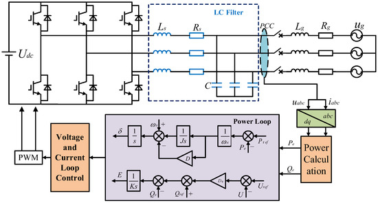
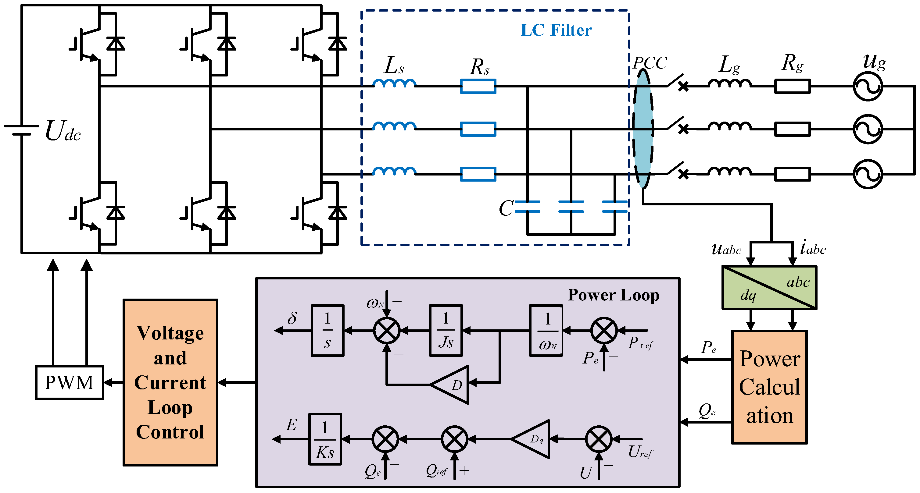
The main circuit and VSG control block diagram are shown in Figure 1.
Figure 1.
The schematic diagram of VSG control.
Wherein, Udc is the DC voltage. ug = (uga,ugb,ugc)T is the grid voltage. u = (ua,ub,uc)T is the voltage of the PCC node. i = (ia,ib,ic)T is the grid current. Ls, is the filter inductance. Rs is the parasitic resistance. C represents the filter capacitance. Lg and Rg are line inductance and resistance.
The VSG control incorporates both an active power–frequency (P–f) control loop and a reactive power–voltage (Q–V) control loop [13]. The P–f control loop can be displayed as
where J is the virtual moment of inertia. and are the output angular frequency and grid angular frequency. is the phase. D is the damping coefficient. Pref is the reference value of active power. Pe is the actual value of active power.
The expression of the Q–V control loop can be displayed as
where E is virtual internal electromotive force. K is the inertia coefficient of simulated excitation regulation. Dq is the reactive power regulation coefficient. Uref and U are the reference voltage and output voltage of VSG, respectively. Qref and Qe are the reference reactive power and output reactive power.
2.2. Fault Analysis Under Unbalanced Grid
For the main circuit shown in Figure 1, when unbalanced faults occur, the unbalanced grid voltage and current in a dq coordinate system can be expressed as
where and are grid voltage and current, respectively. Superscript + and − represent the positive sequence component and negative sequence component. is the angular frequency on the grid side.
According to instantaneous power theory, under unbalanced grid voltage conditions, the instantaneous power injected into the grid can be derived as:
where and are the DC components of instantaneous active and reactive power, respectively. and are the sine and cosine amplitudes of active power fluctuation. and are the sine and cosine amplitudes of reactive power fluctuation, respectively. By comparing Equations (3) and (4), the amplitudes can be calculated.
Under unbalanced conditions, the negative sequence components are not zero, resulting in double-frequency fluctuation of instantaneous power of VSG and imbalance of output current [14].
3. Power–Current Collaborative Control Strategy of VSG Based on Improved SOGI
3.1. An Improved SOGI for Positive and Negative Sequence Separation
The traditional SOGI can be used for sequence separation and filtering signals [15]. The transfer function of SOGI is as follows.
where is the input signal of SOGI. and are the two mutually orthogonal output signals of SOGI. holds a leading phase of 90° compared with . is the angular frequency of the tracking AC signal. k is the gain of the integrator. represents a second-order bandpass filter and represents a low-pass filter. The filtering effect and response characteristics of SOGI are determined by the value of k.
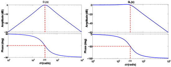
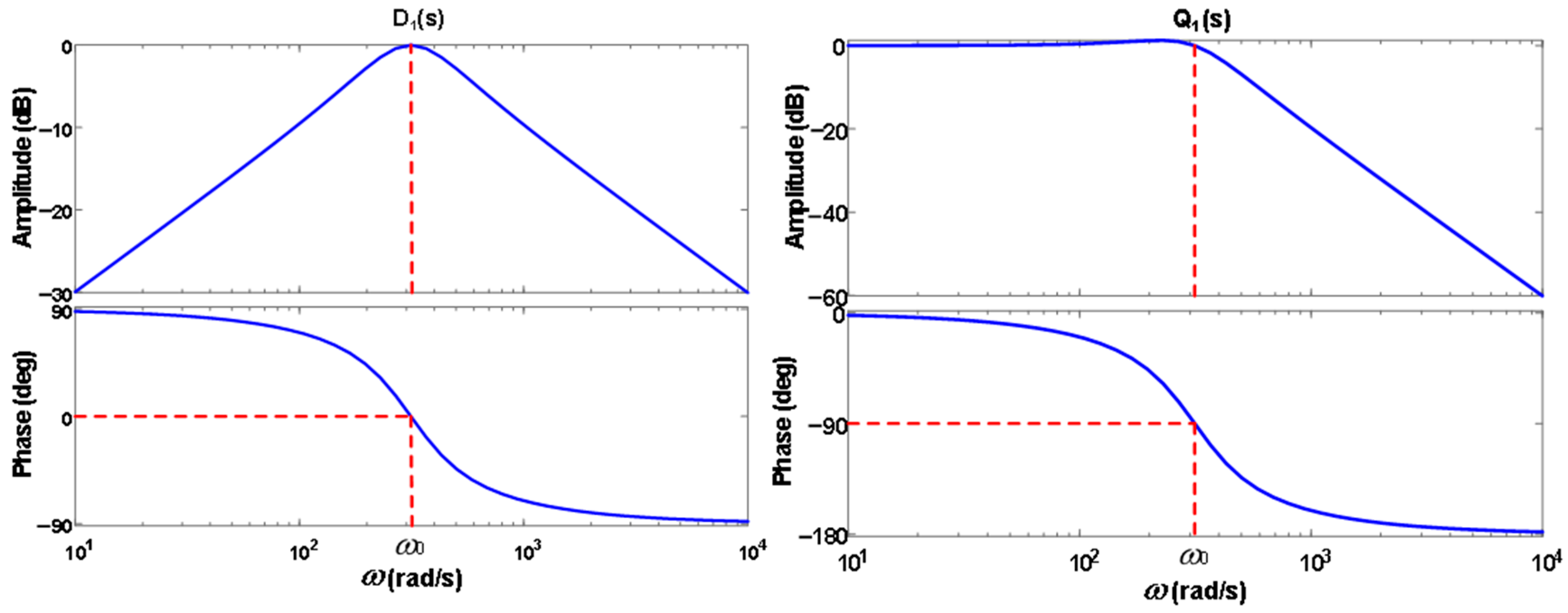
The Bode diagrams of SOGI are shown in Figure 2. SOGI shows good filter performance on high-order harmonics. However, when contains a DC component, is easy to be affected by the DC component, which will introduce errors in signal detection [16]. Thus, DSOGI develops by the differential combination of two SOGIs [17].
Figure 2.
Bode diagrams of and . The red dashed lines correspond to ω0.
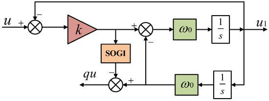
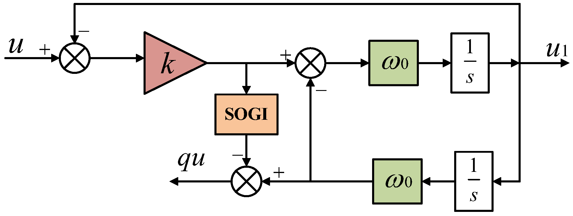
To further enhance the suppression of the DC component, SOGI is improved by introducing a differential node and adding a SOGI module. The schematic diagram of the improved SOGI is depicted in Figure 3.
Figure 3.
Schematic diagram of the improved SOGI.
The transfer function of the improved SOGI can be expressed as.
where k is the gain of the improved integrator. k1 is the gain of the added SOGI. is the internal angular frequency of the added SOGI. In general, = .
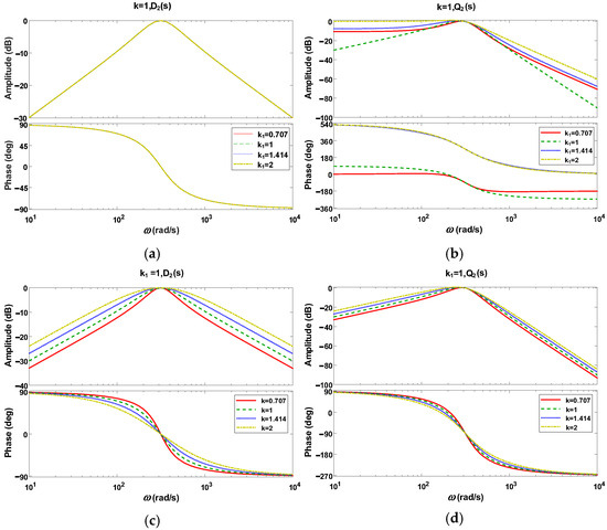
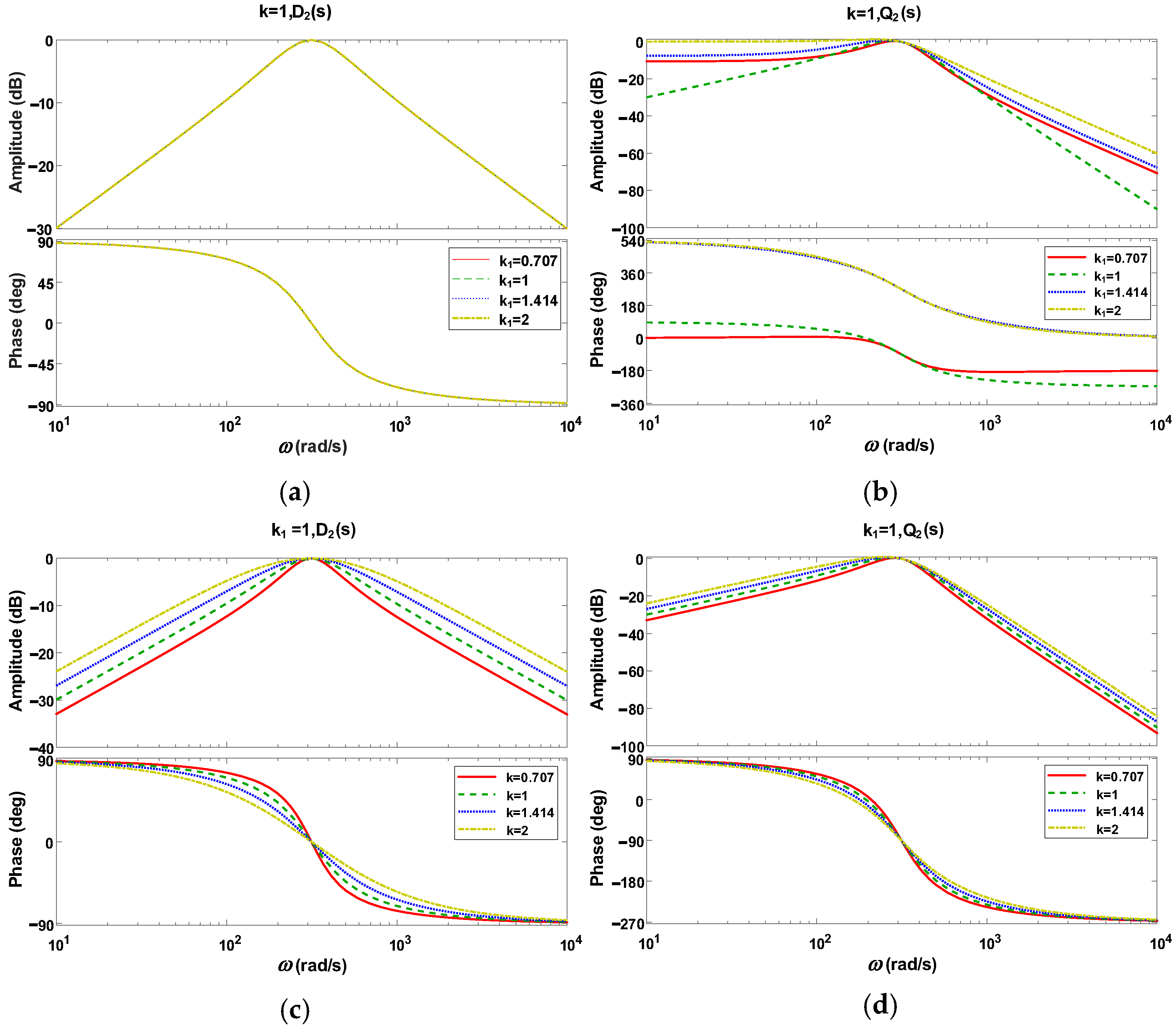
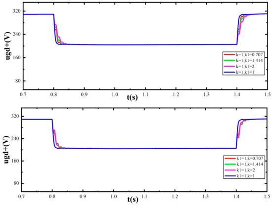
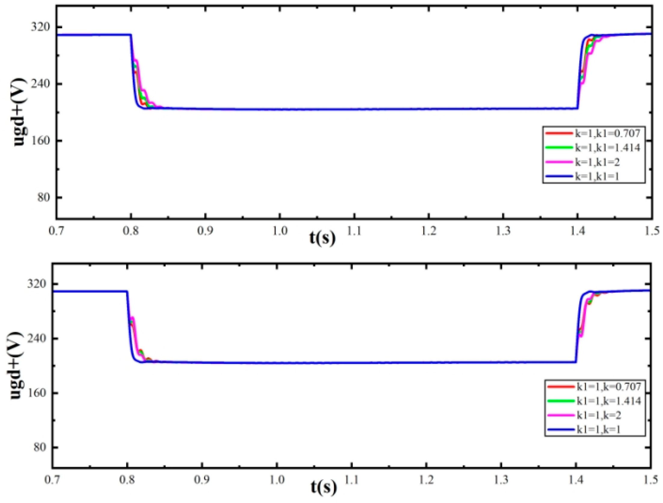
The Bode plots of the improved SOGI with different controller parameter settings are displayed in Figure 4. When the value of k is fixed and k1 is 1, the improved SOGI achieves the optimal filtering performance for DC components and high-order harmonic components. When the value of k1 is fixed, the filtering performance improves with decreasing k. The performance of sequence separation with different k and k1 values are also tested and shown in Figure 5. When k and k1 both equal 1, the system shows the shortest separation time and the smoothest waveform. Thus, the values of k and k1 are selected as 1.
Figure 4.
Bode diagrams of and with different k and k1 values. (a) Bode diagrams of with different k1 values. (b) Bode diagrams of with different k1 values. (c) Bode diagrams of with different k values. (d) Bode diagrams of with different k values.
Figure 5.
Comparison of sequence separation performance with different k and k1 values.
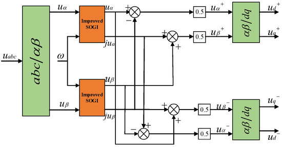
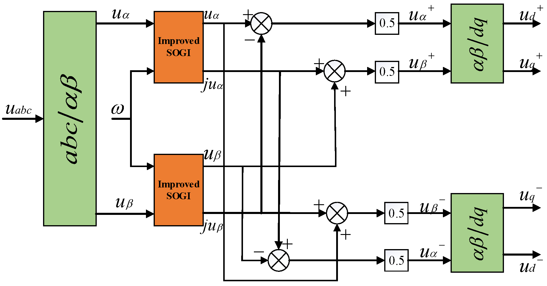
The improved SOGI can achieve rapid separation and effectively suppress harmonics. The overall control structure is displayed in Figure 6.
Figure 6.
Overall control structure of the proposed sequence separation method.
3.2. Power–Current Collaborative Control Strategy
Ignoring the influence of filter capacitor shown in Figure 1, the voltage–current relationship at the inverter output port is described as
where is the voltage of the inverter output port. is the grid voltage. is the grid-connected current. R and L are the equivalent resistances and inductances, respectively.
Following the dq decomposition of the three-phase inverter output voltages oriented to the grid voltage axis, the positive sequence reference current is derived.
where and are the dq components of the positive sequence reference current. and are the dq components of the VSG output voltage.
As analyzed in Section 2.2, under unbalanced conditions, the instantaneous power of the VSG will show double-frequency fluctuation. The output current will be unbalanced. To reduce the fluctuation and imbalance, it is essential to adjust the corresponding negative sequence current reference [18]. Three control objectives have been set for the adjustment. Objective (a) is constant active power. Objective (b) is three-phase current balance. Objective (c) is constant reactive power.
To achieve objective (a), the sine and cosine amplitudes of active power fluctuation in Equation (5) should be set to 0. It is .
Assuming that the negative sequence currents and are only used to suppress power fluctuations and do not participate in the provision of total power and , the solution can be obtained.
To achieve objective (b), set .
To achieve objective (c), the sine and cosine amplitudes of reactive power fluctuation in Equation (5) should be set to 0. It is .
It can be solved as follows.
The above three control objectives are mutually independent. To achieve the collaborative control of current and active/reactive power, a correlation coefficient is introduced with a value range of [−1, 1]. The unified equation of negative sequence current command is established.
When , the control objective is constant reactive power. When , the control objective is the balance of three-phase currents. When , the control objective is constant active power. By adjusting the value of , continuous changes among the three objectives can be achieved. The control performance can be adjusted according to the requirement of concrete cases.
3.3. Current-Limiting Control Strategy
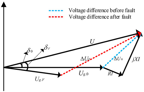
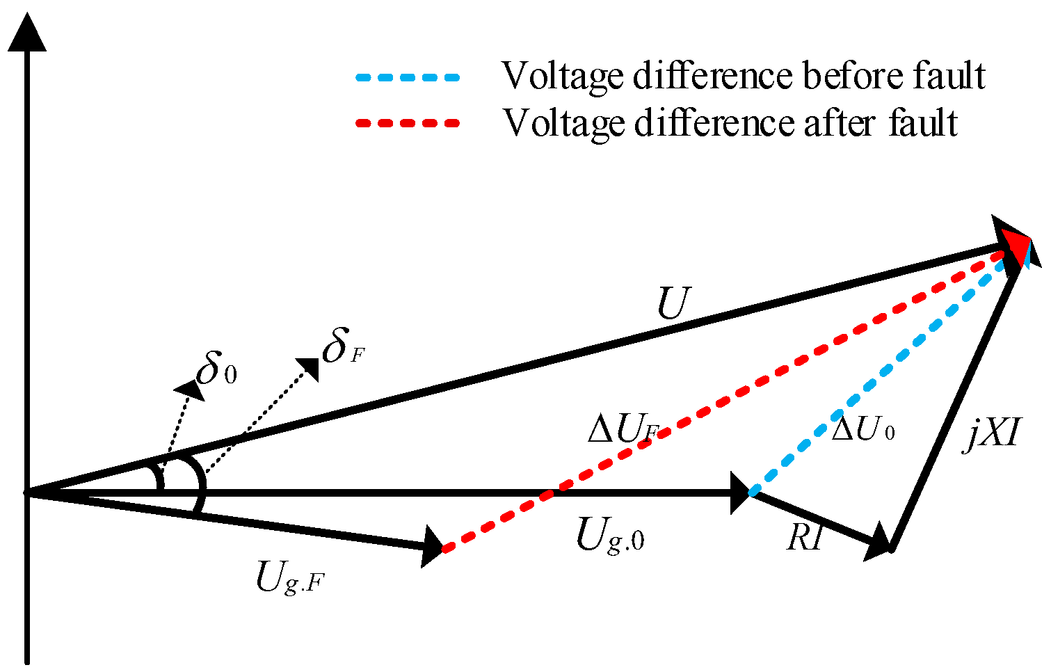
Figure 7 illustrates the vector diagram before and after grid fault. Wherein, U is the VSG output voltage. and are the amplitude of grid voltages before and after fault, respectively. and are the phase shift of the VSG output voltage relative to the grid voltage before and after fault, respectively. When the grid voltage changes from to after a fault, due to the voltage source characteristics, VSG maintains the same port output voltage as that before fault. A large voltage difference between and generates. Because the system impedance R and X are small, a large overcurrent generates. If current-limiting measures are not taken, then stable operation will be influenced [19].
Figure 7.
Voltage vector diagram before and after fault.
Virtual impedance offers an effective means to reduce the overcurrent after fault [20]. The voltage drops caused by virtual impedance in the dq coordinate system is calculated in Equation (17).
wherein, and are the virtual resistance and virtual inductance. id and iq are the dq-axis components of grid current. and are the dq-axis components of voltage drop by adding virtual impedance, respectively. The parameter tuning of the virtual impedance can be referenced in reference [21]. In this study, and are set to 0.1 and 3.14 mH, respectively.
The addition of virtual impedance changes the impedance characteristics of the system, which may cause the instability of the VSG. Thus, virtual impedance only works when overcurrent generates. When a fault occurs, the virtual impedance is introduced. The virtual impedance is deactivated when the fault is cleared.
Reactive power support is important for the grid during asymmetric voltage drop [22,23,24]. According to the national grid connection requirements, the required reactive current is expressed as follows.
wherein, is the per-unit value of the voltage at PCC. is the rated value of the grid current. is the reference value of reactive current provided. When , the VSG outputs additional reactive current as . When , the VSG outputs additional reactive current as . When , the VSG does not output additional reactive current.
The reference value of active current is calculated as follows.
The reference values of power are calculated as
wherein, is the d-axis component of the voltage at PCC. and are the reference values of the VSG output active power and reactive power during fault, respectively.
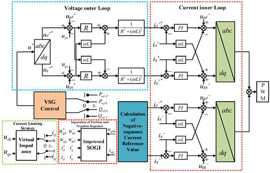
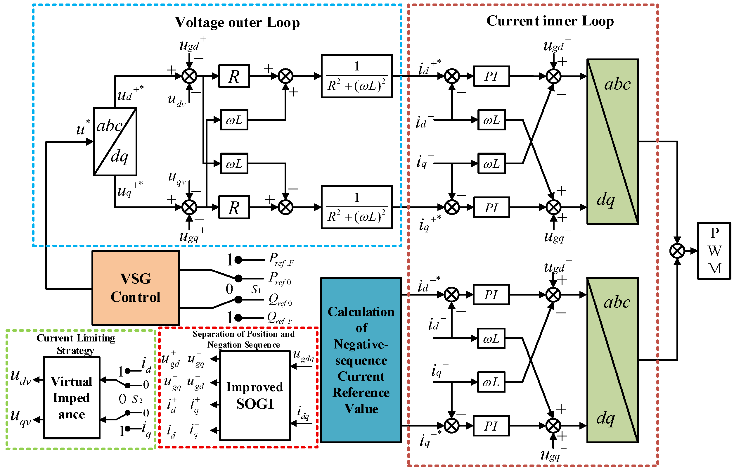
To sum up, the overall structure diagram of the proposed control strategy is shown in Figure 8. It contains four parts of VSG control, power–current collaborative control, sequence separation based on improved SOGI, and virtual impedance overcurrent-limiting control. During the voltage asymmetry fault period, the active power, reactive power, and three-phase current are controlled by adjusting the negative sequence current reference value. In addition, switch S1 is closed. VSG provides reactive power support. If the grid current exceeds the limit, switch S2 is closed and the overcurrent is limited through the virtual impedance. After the fault is removed, switches S1 and S2 open and the system returns to normal operation.
Figure 8.
Overall structure diagram of the proposed control strategy.
4. Case Study
4.1. Case Settings
The main circuit model displayed in Figure 1 was constructed by MATLAB 2023b/Simulink. The system parameter settings are presented in Table 1. The case settings are presented in Table 2. The rated current of the power grid is set as In = 64.3 A. The upper limit of the current is set as Ilim = 1.1In.
Table 1.
Parameter settings.
Table 2.
Case settings.
4.2. Verification of Improved SOGI
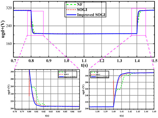
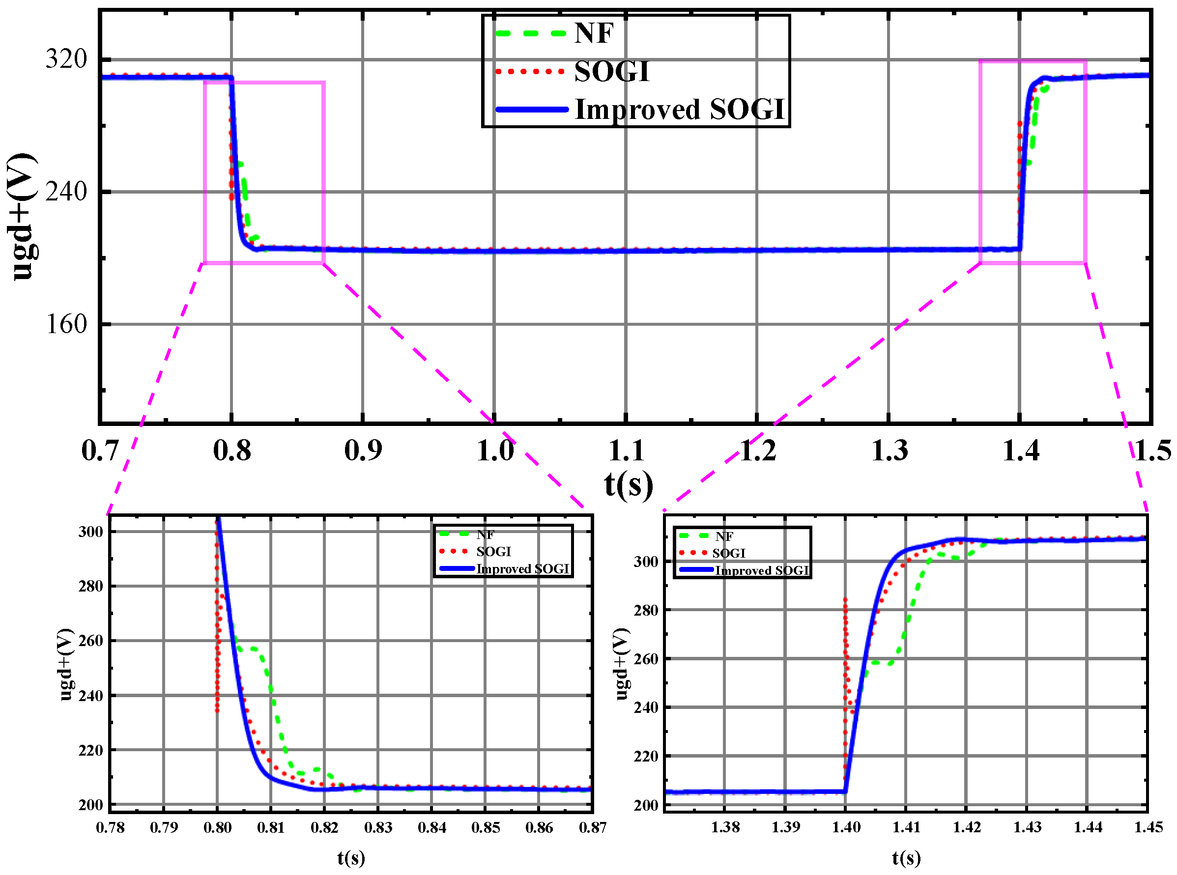
To prove the advantages of the sequence separation method by the proposed improved SOGI, three methods of notch filter (NF), DSOGI, and improved SOGI are used and compared. Case 1 is simulated. The waveforms are shown in Figure 9 and the separation time comparison is presented in Table 3. NF, DSOGI, and improved SOGI can effectively separate the positive sequence component. The separation time of the improved SOGI is the shortest among the three methods. In addition, the waveform during the separation process is smoother and more stable than the other two methods. It indicates that the proposed improved SOGI method is more efficient and stable for positive and negative sequence separation.
Figure 9.
Waveform comparison of the three sequence separation methods.
Table 3.
Comparison of Separation Time.
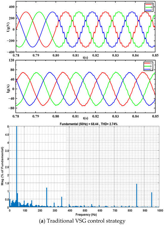
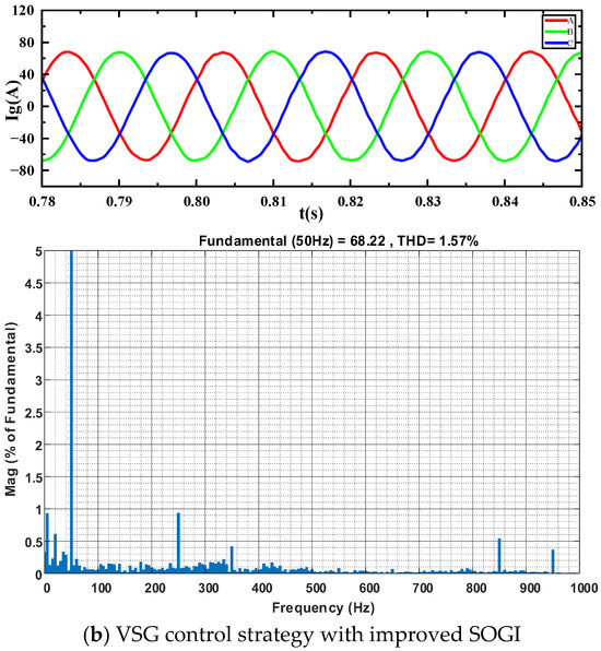
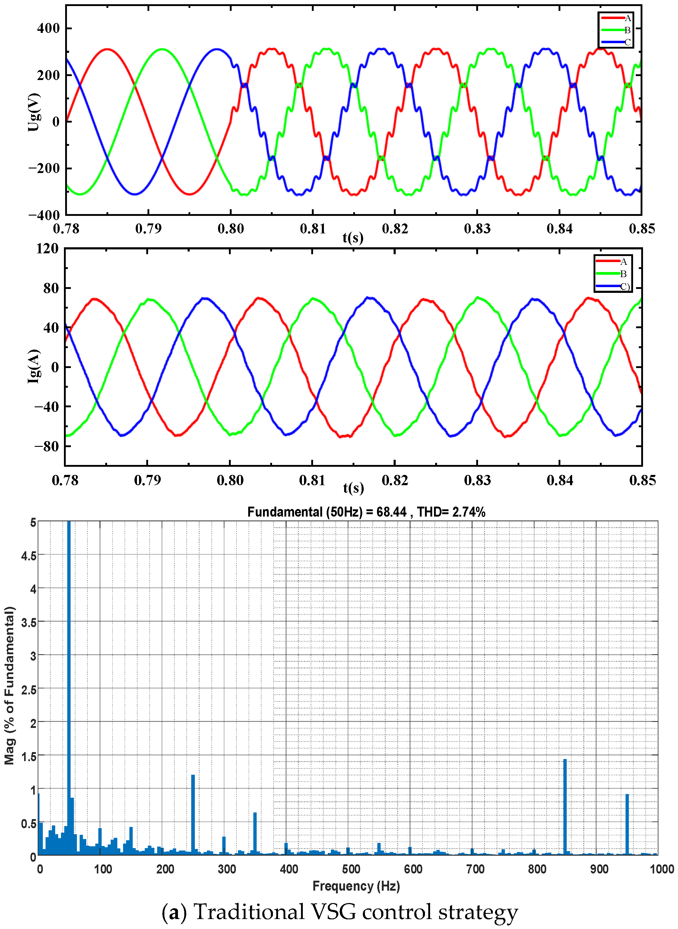
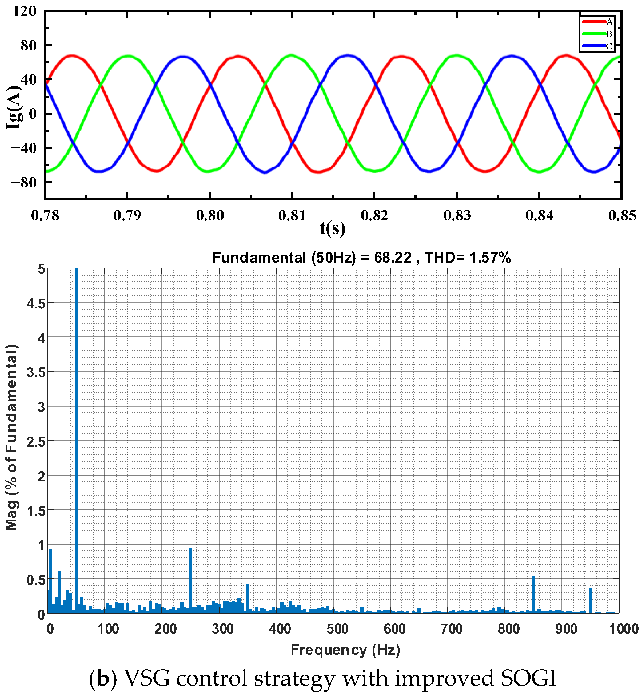
To verify the filtering performance of the improved SOGI on high-order harmonics, case 2 is simulated. The power grid current waveform and FFT analysis of the traditional VSG control and the VSG control with improved SOGI are displayed in Figure 10. Without the improved SOGI strategy, the THD of the current reaches 2.74%. The amplitudes of the −17th and +19th harmonics exceed 0.9%. When the improved SOGI is adopted, the THD of the output current is reduced to 1.57%. The amplitudes of the −17th and +19th harmonics are less than 0.6%. The results indicates that the control with the improved SOGI has better filtering performance on high-order harmonics and suppression effect on noise.
Figure 10.
Current waveform and FFT analysis of the traditional VSG control (a) and the VSG control with improved SOGI (b).
4.3. Verification of Power–Current Collaborative Control Strategy
To verify the validation of the control strategies with the three individual objectives, case 3 is simulated. The results are displayed in Table 4. When control objective (a) is achieved, the peak value of active power fluctuation is obviously decreased, realizing constant output of active power. When control objective (b) is achieved, the unbalance rate of the output current is greatly decreased, and the three-phase output current maintains balanced operation. When control objective (c) is achieved, the peak value of reactive power fluctuation is substantially reduced, achieving constant reactive power output.
Table 4.
Comparison of Simulation Results of Three Control Objectives.
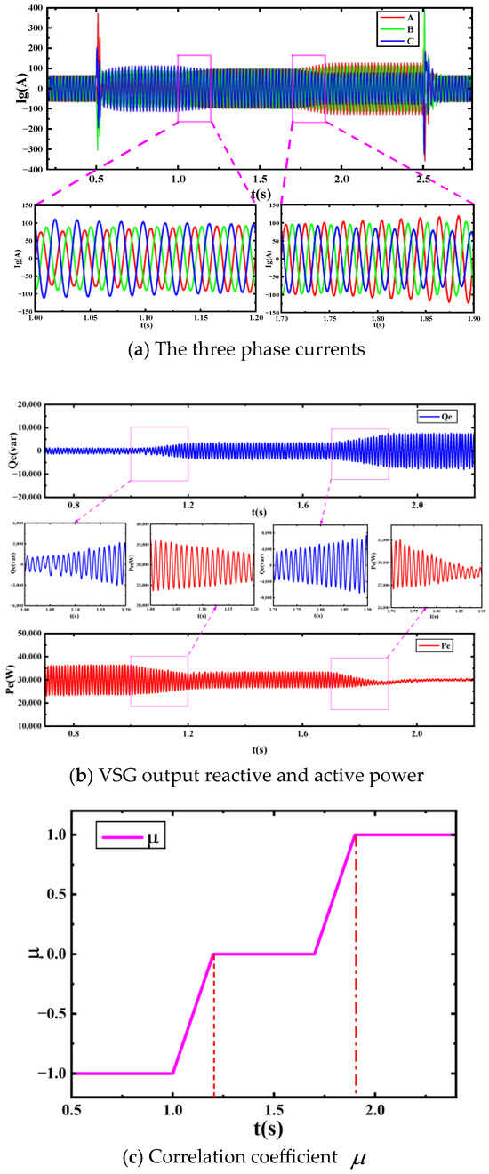
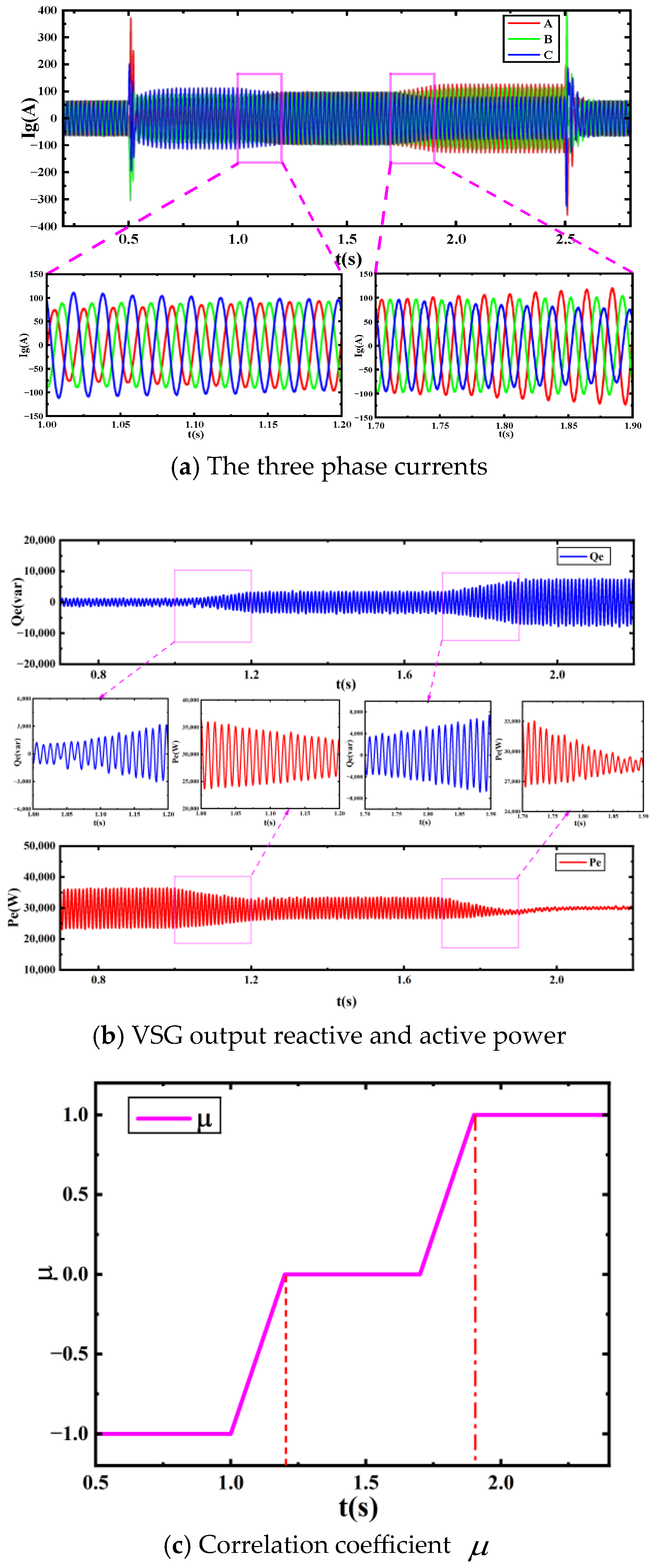
To further verify the power–current collaborative control performance, case 4 is simulated. The simulation waveforms are displayed in Figure 11. The values −1, 0, and 1 of the correlation coefficient correspond to the control objectives of reactive power control, three-phase current balance control, and active power control. By unifying the control strategy in one equation as Equation (16), continuous operation and smooth switching among the three control objectives are achieved.
Figure 11.
Simulation results of power–current collaborative control strategy.
4.4. Verification of Overcurrent-Limiting Control Strategy
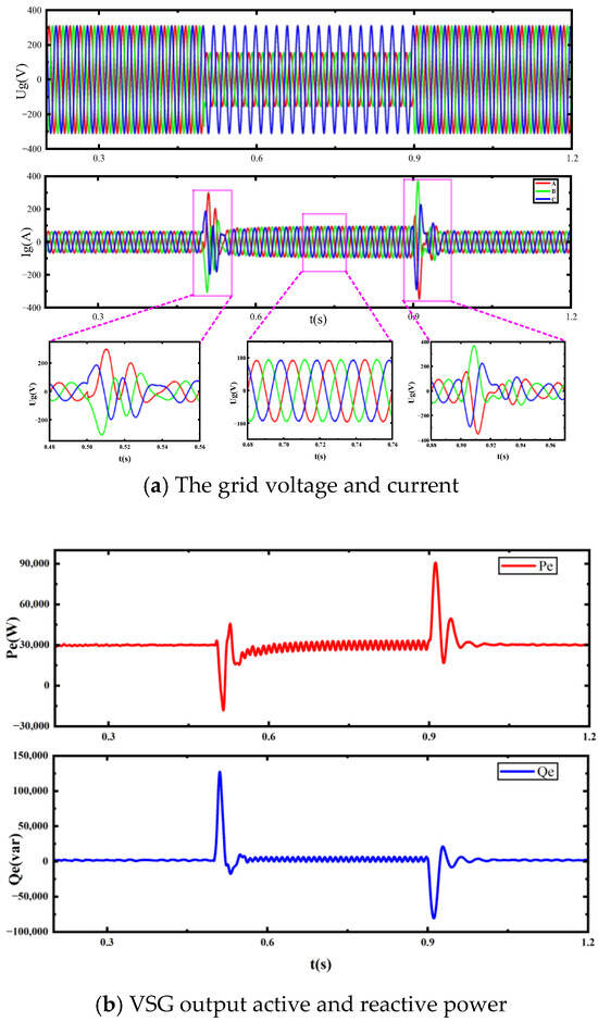
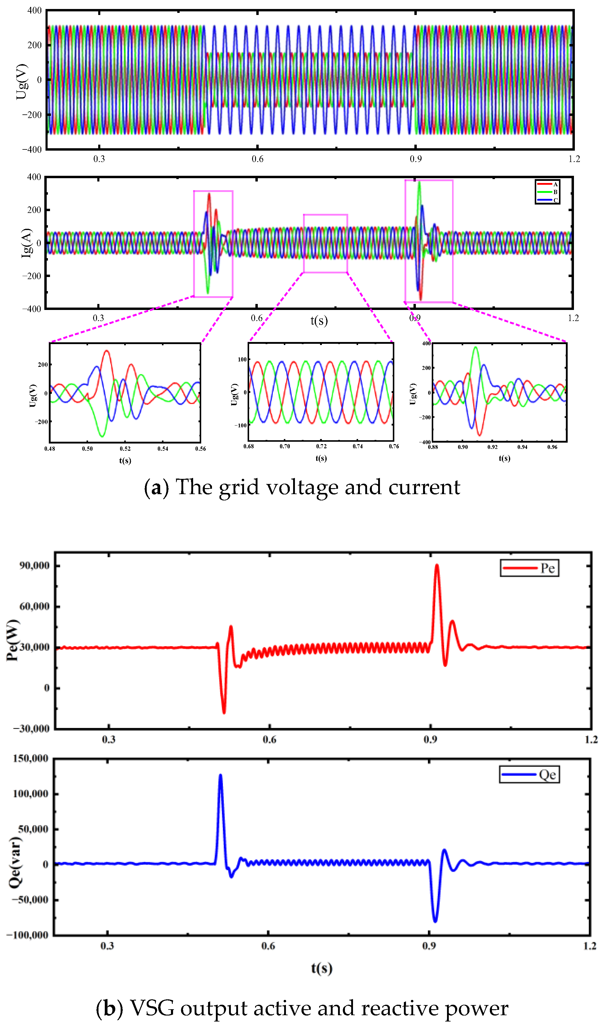
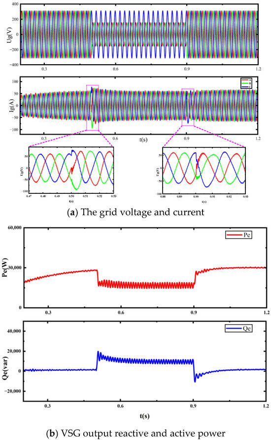
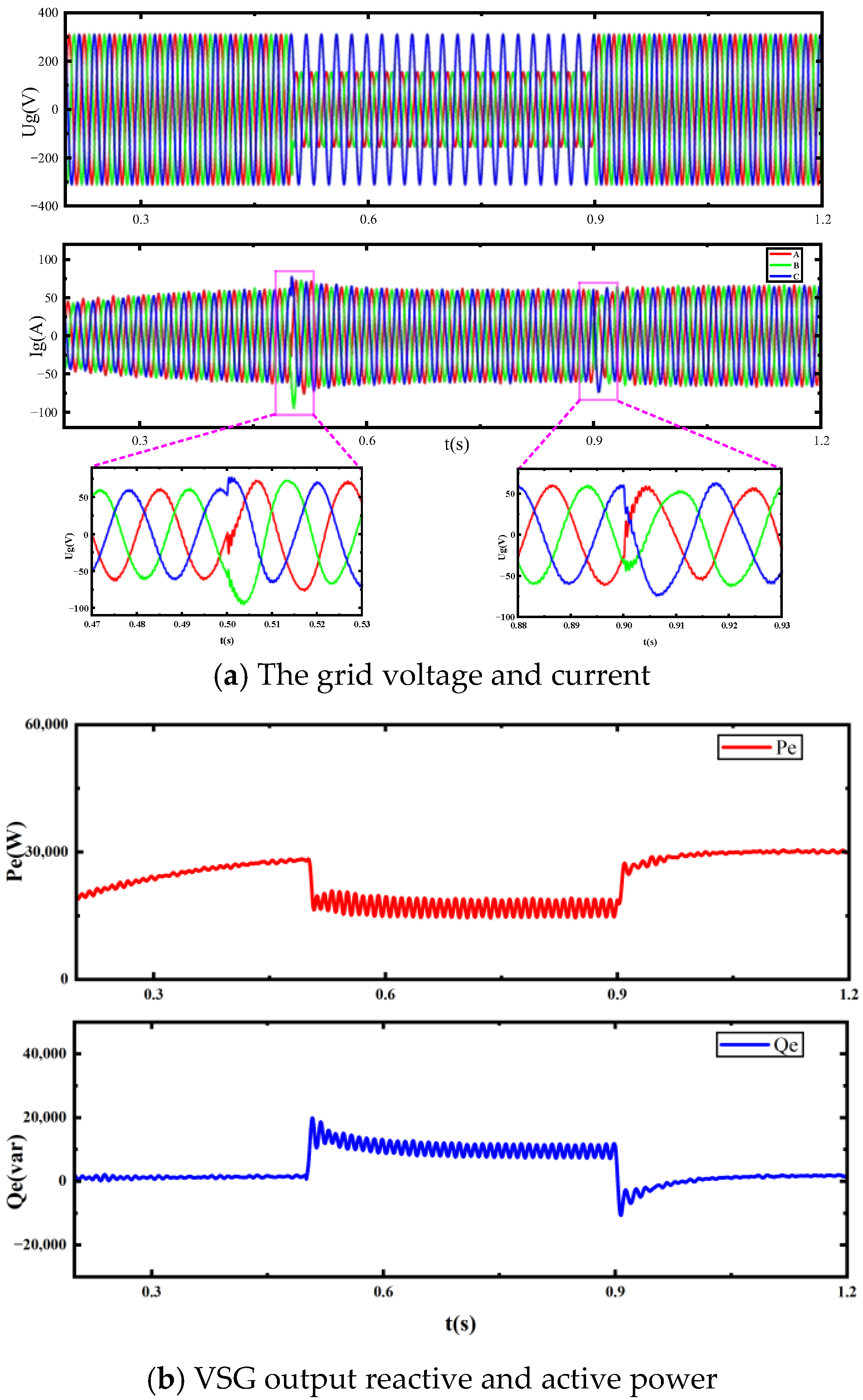
To verify the overcurrent-limiting effect of virtual impedance and the supporting of VSG output reactive power on the power grid, case 5 is simulated on the basis of three-phase current balance control. Figure 12 and Figure 13 illustrate the waveforms without the overcurrent-limiting strategy and with the overcurrent-limiting strategy.
Figure 12.
Waveforms without overcurrent-limiting strategy.
Figure 13.
Waveforms with overcurrent-limiting strategy.
When the overcurrent-limiting control strategy is not adopted, the steady-state overcurrent reaches 97.2 A during the fault period. This is 1.51 times the rated current. The transient current reaches 321.2 A at the voltage drop beginning, which is 5 times the rated current. The transient current reaches 395.3 A at the voltage recovery beginning, which is 6.1 times the rated current. In addition, the power exhibits large fluctuations and overshoot.
When the overcurrent-limiting control strategy is adopted, the transient current is 96.3 A at the voltage drop beginning. The fault duration is only 7 ms. Then, the fault current is limited below the upper limit during fault and recovery. In addition, the fluctuation and overshoot of power are small at the time of fault occurrence and recovery. The converter increased reactive power output during the fault, which ensured the reactive power support for the power grid.
The comparison of simulation data without and with the current-limiting strategy are listed in Table 5. Wherein, represents the amplitude of steady-state overcurrent. and indicate the amplitude of transient overcurrent at fault beginning and fault ending, respectively. and indicate the duration of transient overcurrent at fault beginning and fault ending, respectively. When the overcurrent-limiting control strategy is adopted, the output current amplitude and transient overcurrent duration are significantly reduced, ensuring stable operation under an unbalanced power grid.
Table 5.
The comparison of simulation results without and with overcurrent-limiting strategy. (System rated current In = 64.3 A).
4.5. Verification of the Proposed Strategy in Weak Grid
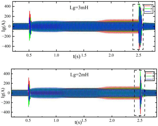
In the cases above, the inductance parameter Lg = 1 mH, i.e., SCR = 10. According to the IEEE std 1204-1997(R2003) standard [25], it corresponds to a strong grid scenario. To verify the validation of the proposed control strategy under weak grid conditions, case 6 is simulated. A weak grid (Lg = 2 mH, i.e., SCR = 2.5) and an extremely weak grid (Lg = 3 mH, i.e., SCR = 1.14) is simulated. The results are displayed in Figure 14.
Figure 14.
The three-phase currents in case 6 with different Lg values.
Compared with the waveforms in Figure 11a, with the reduction in grid strength, the transient period lasts longer. However, under both of the weak grid scenarios, the system can regain stability, which demonstrates the applicability of the proposed control approach.
4.6. Applicability of the Proposed Strategies Under Different Unbalanced Scenarios
To verify the validation of the proposed strategy under different unbalanced conditions, case 7 and case 8 are simulated. The corresponding simulation results are depicted in Figure 15 and Figure 16. The proposed power–current collaborative control strategy is effective under both the unbalanced scenario of single-phase voltage drop and the unbalanced scenario of three-phase voltage drop to a different extent. Thus, the application of the proposed strategy to more unbalanced scenarios has been verified.
Figure 15.
Waveforms under the scenario of Uga drop 30%.
Figure 16.
Waveforms under the scenario of Uga drop 30%, Ugb drop 50% and Ugc drop 70%.
5. Conclusions
In an unbalanced power grid, the VSG shows the problems of output current imbalance, power fluctuation, and overcurrent. Thus, a VSG power–current collaborative control strategy based on an improved SOGI is proposed. To overcome the limitations of SOGI in sequence separation, an improved SOGI is proposed by adding a differential node and an extra SOGI module to the traditional SOGI. Both the DC component and high-order harmonic components are effectively suppressed. Then, collaborative control of the three objectives is achieved by introducing a correlation coefficient μ. In addition, virtual impedance and the reactive power reference value are introduced to prevent overcurrent and improve transient stability. Simulations have verified the effectiveness of the proposed strategy. It shows advantages in improving power quality and ensuring safe operation in an unbalance power gird. In our future research, the analysis of the overall system stability, parameter security domain, and the verification of hardware experiments, will be focused on. The applicability of the proposed strategy to the parallel operation of multiple VSGs will also be discussed.
Author Contributions
Y.Q. (corresponding author): conceptualization, methodology, investigation, formal analysis, and writing—original draft; C.W.: methodology, software, validation, and writing—original draft; F.W.: software, validation, and writing—review and editing, and visualization; W.P.: conceptualization, resources, supervision, and writing—review and editing. All authors have read and agreed to the published version of the manuscript.
Funding
This research was funded by the Comprehensive Research Program of CNOOC Limited: “Research on Action Mechanism and Control Strategy Application of Grid-Forming Technology in Offshore Oil & Gas Field Power Grids” (KJZH-2024-2601).
Data Availability Statement
No datasets were generated or analyzed during the current study.
Conflicts of Interest
Authors Yinfeng Qiu, Che Wei and Fan Wang were employed by the company CNOOC Research Institute Ltd. The remaining authors declare that the research was conducted in the absence of any commercial or financial relationships that could be construed as a potential conflict of interest.
References
- Chi, Y.; Liang, W.; Zhang, Z. An overview on key technologies regarding power transmission and grid integration of large scale offshore wind power. Proc. CSEE 2016, 36, 3758–3770. [Google Scholar]
- Chen, M.; Zhou, D.; Blaabjerg, F. High penetration of inverter-based power sources with VSG control impact on electromechanical oscillation of power system. Int. J. Electr. Power Energy Syst. 2022, 142, 108370. [Google Scholar] [CrossRef] [Scilit]
- Liu, Q.; Pang, S.; Wu, L. The mechanism, factors and influence rules of voltage imbalance in wind power integration areas. Trans. China Electrotech. Soc. 2022, 37, 5435–5450. [Google Scholar]
- Pan, Z.; Yang, X.; Zhao, R. Multi-Mode Coordination Control of Virtual Synchronous Generator Under Unbalanced Power Grid. Trans. China Electrotech. Soc. 2023, 38, 4274–4285. [Google Scholar]
- Tian, Y.; Yuan, H.; Zhu, W.; Li, X.; Li, Y. Sliding Mode Control of Vienna Rectifier Under Unbalanced Weak Power Grid. IEEE Access 2024, 12, 39095–39109. [Google Scholar] [CrossRef] [Scilit]
- Bamigbade, A.; de Leon, F. Secure Voltage-Modulated Vector Current Control of Distributed Energy Resources Using Delayed DSOGI Under Distorted and Unbalanced Grid Conditions. IEEE Trans. Ind. Appl. 2025, 61, 1091–1101. [Google Scholar] [CrossRef] [Scilit]
- Li, S.; Cao, P.; Li, X.; Jiang, X.; Liang, Y. Improved VSG Control Strategy for Photovoltaic-storage Systems Under Grid Voltage Imbalance. Guangdong Electr. Power 2024, 37, 63–69. [Google Scholar]
- Zheng, X.; Wang, C.; Pang, S. Injecting positive-sequence current virtual synchronous generator control under unbalanced grid. IET Renew. Power Gener. 2019, 13, 165–170. [Google Scholar] [CrossRef] [Scilit]
- Wan, X.; Hu, H.; Nie, X. An improved control strategy for virtual synchronous generator under unbalanced grid voltage. Power Syst. Technol. 2017, 41, 3573–3581. [Google Scholar]
- Wang, Y.; Wang, H.; Zhu, B. Control strategy of grid-connected inverter based on VSG under unbalanced grid voltage. Renew. Energy Resour. 2022, 40, 696–702. [Google Scholar]
- Dong, J.; Pan, J.; Mao, X. Low voltage ride-through strategy of VSG based on adaptive positive and negative sequence composite control. Power Syst. Technol. 2023, 47, 815–822. [Google Scholar]
- Wu, W.; Chen, Y.; Zhou, L.; Luo, A.; Zhou, X.; He, Z.; Yang, L.; Xie, Z.; Liu, J.; Zhang, M. Sequence impedance modeling and stability comparative analysis of voltage-controlled VSGs and current-controlled VSGs. IEEE Trans. Ind. Electron. 2019, 66, 6460–6472. [Google Scholar] [CrossRef] [Scilit]
- Wen, T.; Zou, X.; Zhu, D.; Guo, X. Comprehensive perspective on virtual inductor for improved power decoupling of virtual synchronous generator control. IET Renew. Power Gener. 2020, 14, 485–494. [Google Scholar] [CrossRef] [Scilit]
- Zhong, Q.; Nguyen, P.L.; Ma, Z.; Sheng, W. Self-synchronized synchronverters: Inverters without a dedicated synchronization unit. IEEE Trans. Power Electron. 2014, 29, 617–630. [Google Scholar] [CrossRef] [Scilit]
- Ranjan, A.; Kewat, S.; Singh, B. DSOGI-PLL With In-Loop Filter Based Solar Grid Interfaced System for Alleviating Power Quality Problems. IEEE Trans. Ind. Appl. 2021, 57, 730–740. [Google Scholar] [CrossRef] [Scilit]
- Zhang, J.; Chen, Q.; Li, G.; Hu, C. Research on Improve Second Order Generalized Integrator Phase-locked Loop in Non ideal Power Grid. Power Electron. 2021, 55, 1000–1005. [Google Scholar]
- Hoepfner, B.; Vick, R. A DC Rejection Add-On for the Three-Phase Frequency-Fixed DSOGI-PLL. IEEE Trans. Ind. Electron. 2025, 72, 14260–14270. [Google Scholar] [CrossRef] [Scilit]
- Shuai, Z.; Huang, W.; Shen, C.; Ge, J.; Shen, Z.J. Characteristics and restraining method of fast transient inrush fault currents in synchronverters. IEEE Trans. Ind. Electron. 2017, 64, 7487–7497. [Google Scholar] [CrossRef] [Scilit]
- Saffar, K.G.; Driss, S.; Ajaei, F.B. Impacts of current limiting on the transient stability of the virtual synchronous generator. IEEE Trans. Power Electron. 2023, 38, 1509–1521. [Google Scholar] [CrossRef] [Scilit]
- Paquette, A.D.; Divan, D.M. Virtual impedance current limiting for inverters in microgrids with synchronous generators. IEEE Trans. Ind. Appl. 2014, 51, 1630–1638. [Google Scholar] [CrossRef] [Scilit]
- Liu, H.; Wang, Y.; Liu, Y.; Peng, Y.; Li, M.; Lei, W. The LVRT strategy for VSG based on the quantitatively designed virtual impedance. High Volt. Eng. 2022, 48, 245–256. [Google Scholar]
- Liu, G.; Li, X.; Yu, H. The Improved Low Voltage Ride-through Strategy of VSG Based on Fast Delayed Signal Cancellation. Proc. CSU-EPSA 2024, 4, 98–106. [Google Scholar]
- Liemann, S.; Rehtanz, C. Voltage stability analysis of grid-forming converters with current limitation. Electr. Power Syst. Res. 2020, 6, 259–269. [Google Scholar] [CrossRef] [Scilit]
- Yu, Y.; Chaudhary, S.K.; Tinajero, G.D.A.; Xu, L.; Abu Bakar, N.N.B.; Vasquez, J.C.; Guerrero, J.M. A reference-feedforward-based damping method for virtual synchronous generator control. IEEE Trans. Power Electron. 2022, 37, 7566–7571. [Google Scholar] [CrossRef] [Scilit]
- IEEE Std 1204-1997(R2003); IEEE Guide for Planning DC Links Terminating at AC Locations Having Low Short-Circuit Capacities. Transmission and Distribution Committee of the IEEE Power Engineering Society: New York, NY, USA, 2003.
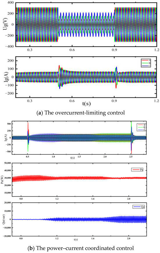
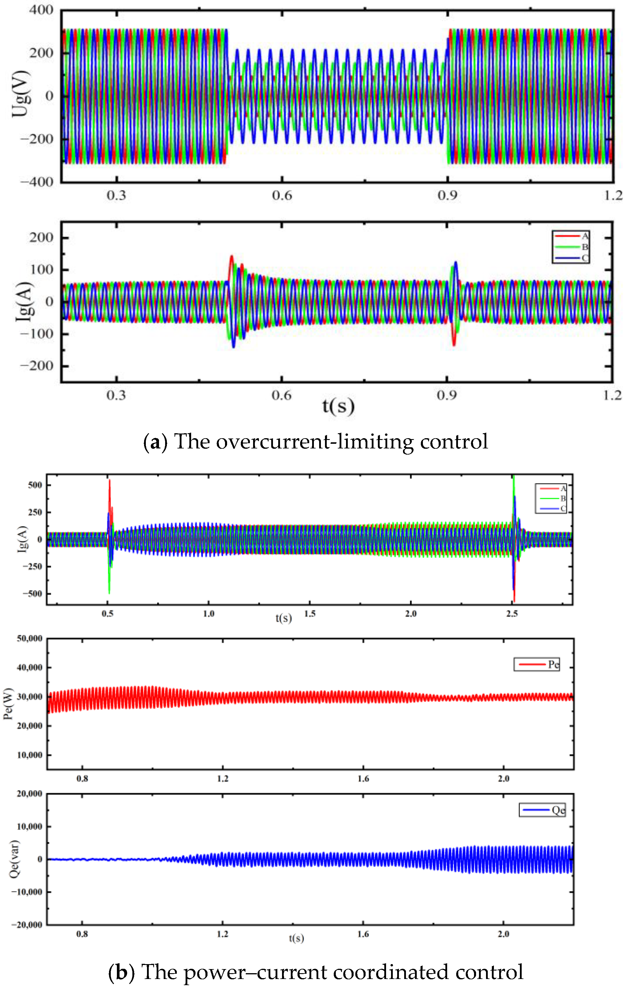

Disclaimer/Publisher’s Note: The statements, opinions and data contained in all publications are solely those of the individual author(s) and contributor(s) and not of MDPI and/or the editor(s). MDPI and/or the editor(s) disclaim responsibility for any injury to people or property resulting from any ideas, methods, instructions or products referred to in the content. |
© 2026 by the authors. Licensee MDPI, Basel, Switzerland. This article is an open access article distributed under the terms and conditions of the Creative Commons Attribution (CC BY) license.