


Abstract
Aviation power systems require extremely high reliability. As a result, rectifiers must be capable of continuing operation during phase-lack faults, where the input voltage of one phase drops to zero. However, traditional fault-tolerant strategies often struggle to maintain effective control under these conditions. To address this issue, this paper proposes a single-phase control strategy specifically designed for the Vienna rectifier, a commonly used component in aerospace power systems. This strategy ensures a stable DC output during phase-lack faults while maintaining low total harmonic distortion and a near-unity power factor. Simulation results confirm the effectiveness of the proposed control method.
1. Introduction
With the rapid advancement of aviation technology and the continuous expansion of global transportation networks, the demand for air traffic has been steadily increasing, making the More Electric Aircraft (MEA) concept a key development trend in the aerospace field [1,2,3]. Meanwhile, both the quantity and power density of onboard electrical and electronic systems have been increasing, leading to a significant rise in the complexity of the aircraft power supply system. However, this evolution also brings new challenges [4,5,6].
The widespread adoption of power electronic converters, while improving energy utilization efficiency, inevitably causes harmonic distortions, voltage fluctuations, and phase imbalances, thereby deteriorating the overall power quality of the aircraft electrical network [7,8,9,10]. In this context, the Vienna rectifier, characterized by a high power factor, low harmonic distortion, high efficiency, and superior current quality, serves as an ideal solution for aircraft power conversion systems [11,12]. Compared with conventional diode rectifiers or three-level PWM rectifiers, the Vienna topology exhibits significant advantages in terms of the number of switching devices, the loss distribution, and thermal stress management [13,14]. It enables stable operation under stringent aerospace requirements, where high reliability and a lightweight design are equally emphasized. In particular, under harsh conditions such as high altitudes, wide-frequency variable power supply, and asymmetric load scenarios, the Vienna rectifier can still maintain excellent dynamic performance and stable voltage balance control [15,16] in airborne power systems, and high reliability has always been the primary design goal. Due to the safety-critical nature of onboard applications, when abnormal operating conditions occur—such as phase-lack faults, short circuits, grid voltage asymmetry, or line disconnections—the rectifier is required not only to maintain basic energy transmission but also to ensure balanced input currents and stable DC bus voltage [11,17].
This imposes stringent requirements on the control performance of power electronic converters. In particular, for the Vienna rectifier, which is widely used in MEA power systems, achieving a balance between fault-tolerant capability and dynamic performance under the constraints of high power density and lightweight design has become a critical challenge. In various abnormal operating conditions, a short circuit is typically easy to detect and handle due to pronounced current surges and clearly triggered protection actions [18,19]. In contrast, open-circuit and phase-lack faults exhibit more subtle characteristics, primarily affecting the performance of the rectifier rather than directly activating protective mechanisms. Notably, in practical operation, the occurrence probability of the open circuit can reach approximately 34% [20], while three-phase unbalanced conditions are also commonly observed in aircraft power systems [21,22,23]. However, research on phase-lack control remains relatively limited.
Common fault-tolerant strategies can be categorized into two primary approaches: The first aims to enhance system redundancy through hardware upgrades [18,19]. The second approach, in contrast, utilizes advanced digital control algorithms for effective fault detection and compensation [24,25,26,27,28]. In practical engineering applications, most fault-tolerant schemes favor digital control strategies. This tendency reduces the need for extensive hardware expansion and simplifies system processes. Within these digital control frameworks, modulation strategies generally fall into two key types: Space Vector Pulse-Width Modulation (SVPWM) and Carrier-based Pulse-Width Modulation (CB-PWM) [24,25]. Furthermore, research has demonstrated that fault-tolerant operations can be executed under the open-circuit conditions by adjusting the switching sequence of space vectors. Despite this, SVPWM encounters significant drawbacks in airborne power systems. Aircraft electrical networks typically operate at frequencies that are more than six times those of terrestrial grids. This requires converters capable of much higher switching frequencies. In such scenarios, the complex sector-identification and time-calculation processes inherent in SVPWM algorithms place a substantial computational load on real-time controllers. These complexities can constrain the achievable switching frequency. This compromises the effectiveness of SVPWM in high-frequency, lightweight, and reliability-critical aircraft power conversion systems. Consequently, CB-PWM has gained traction as an emergent focus in fault-tolerant control. This is due to its ease of implementation, control flexibility, and excellent adaptability to high-frequency environments. When compared to conventional SVPWM methods, CB-PWM significantly reduces both computational complexity and control delays. CB-PWM ensures exceptional current quality and stable neutral-point voltage. These benefits remain even at elevated switching frequencies. The advantages of CB-PWM position it as a superior choice for next-generation aircraft power systems [26,27,28].
In the event of the phase-lack fault, the Vienna rectifier can be regarded as an equivalent single-phase full-bridge Vienna rectifier, with the remaining two phases providing the line-to-line voltage as the input. Building on this observation, as reported in [29], the Vienna rectifier under the phase-lack scenario is treated as a single-phase topology for control design. However, because the proposed method in [29] uses SVPWM, as already discussed, it is less suited to aerospace power systems that require high switching frequencies and high reliability [30]. Based on current vector modulation, a model predictive current control strategy with an optimal modulation index was proposed, which effectively alleviates grid current distortion. Furthermore, ref. [31] introduced a model predictive direct power control method with dual-vector modulation for current-source rectifiers, mitigating power ripples. However, neither of these methods can be directly applied to voltage-source Vienna rectifiers, and both still inherit the inherent drawbacks of SVPWM.
To directly address the limitations noted above, this paper proposes a CB-PWM-based phase-lack control strategy that ensures fault-tolerant operation of the Vienna rectifier under phase-lack conditions while maintaining stable output voltage, THD, and PFC. The proposed phase-lack control strategy addresses the research gap in CB-PWM-based phase-lack control of the Vienna rectifier for aerospace applications, overcoming the computational burden of traditional SVPWM methods at high switching frequencies [32]. The third-harmonic injection method based on CB-PWM can effectively mitigate current zero-crossing distortion; however, this approach is not suitable for post-fault equivalent single-phase circuits.
The structure of this paper is organized as follows: First, the topology of the three-phase Vienna rectifier is introduced, and its operating characteristics under the phase-lack condition are analyzed in detail. Next, the proposed fault-tolerant control strategy is presented, followed by the derivation of the system’s mathematical model under fault conditions, which forms the basis for designing the corresponding controller. Finally, simulation and experiment results are provided to validate the effectiveness of the proposed control strategy.
2. Phase-Lack Analysis of Vienna Rectifiers
2.1. Basic Principle of Vienna Rectifiers
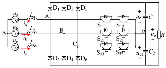
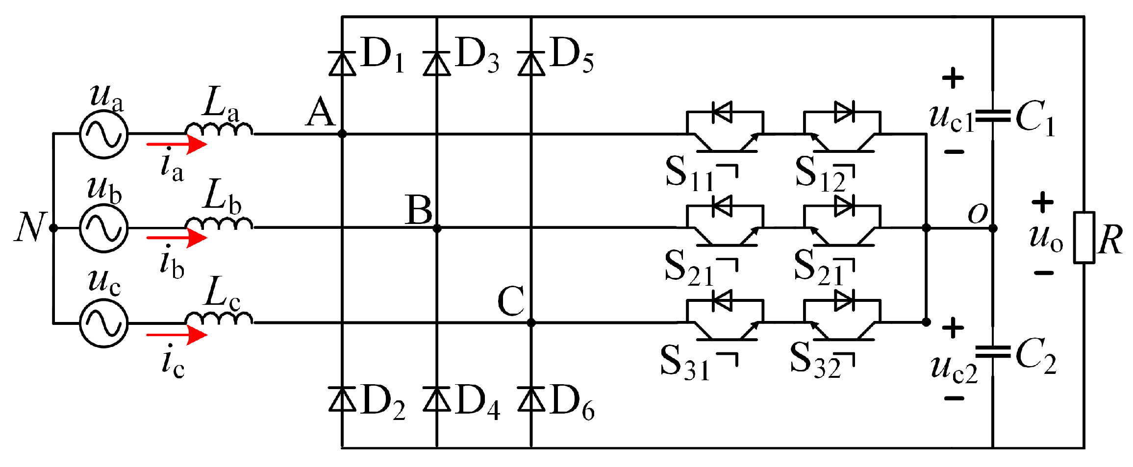
Figure 1 illustrates the circuit topology of a three-phase Vienna rectifier. The converter consists of six power switches ( and ), two dc-link capacitors ( and ), three input filter inductors (, and ), and six rectifier diodes (). and are the three-phase input voltages, and and are the three-phase input currents. The midpoint of the DC link is defined as O, and the voltages of the upper and lower capacitors are denoted as and , respectively. A, B, and C are the nodes on the AC side. Through appropriate modulation and control strategies, the voltage balance between the two capacitors can be dynamically maintained [33].
Figure 1.
Topology of the three-phase Vienna rectifier.
2.2. Phase-Lack Faults
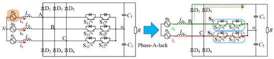
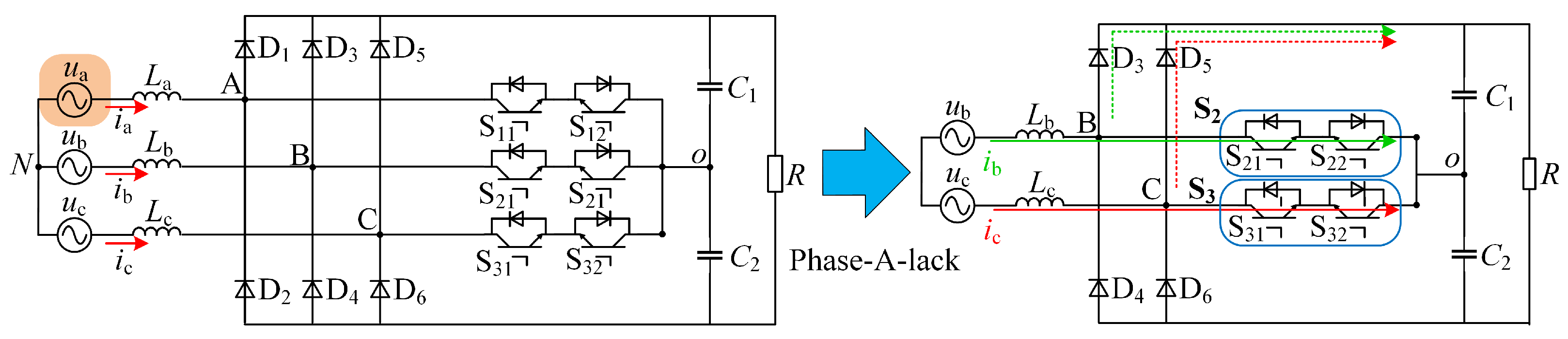
The corresponding schematic diagram describing when a phase-lack fault occurs in phase A is shown in Figure 2.
Figure 2.
Schematic diagram of a phase-A-lack fault.
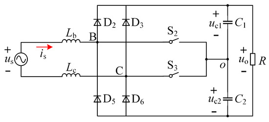
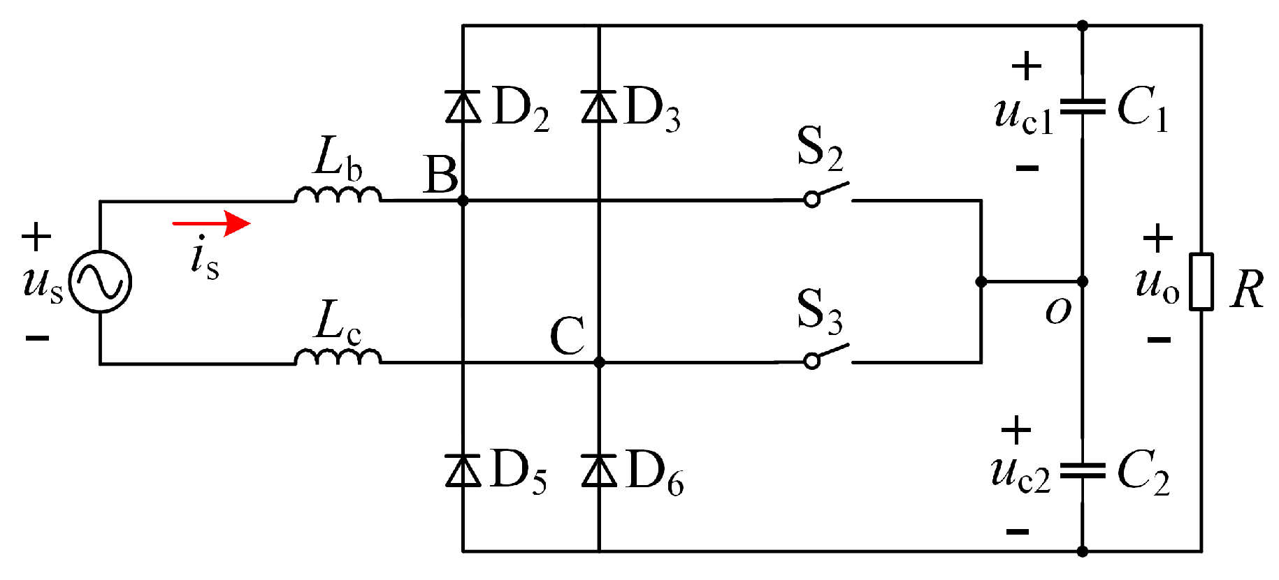
The phase-lack fault causes a disruption of the current balance among the three phases, forcing to have the same magnitude but opposite direction as . According to Figure 2, the current directions of phases B and C depend on the bidirectional switches and , which consist of , , and , and , respectively. When the corresponding switches are turned on, the current flows along the solid lines; otherwise, it flows along the dashed lines. and have four possible switching states, namely , , , and . The voltages of phases B and C can be represented by the line voltage . The equivalent circuit of the Vienna rectifier (ECVR) under the phase-lack condition is presented in Figure 3.
Figure 3.
ECVR.
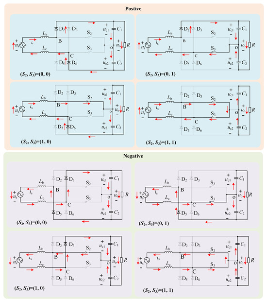
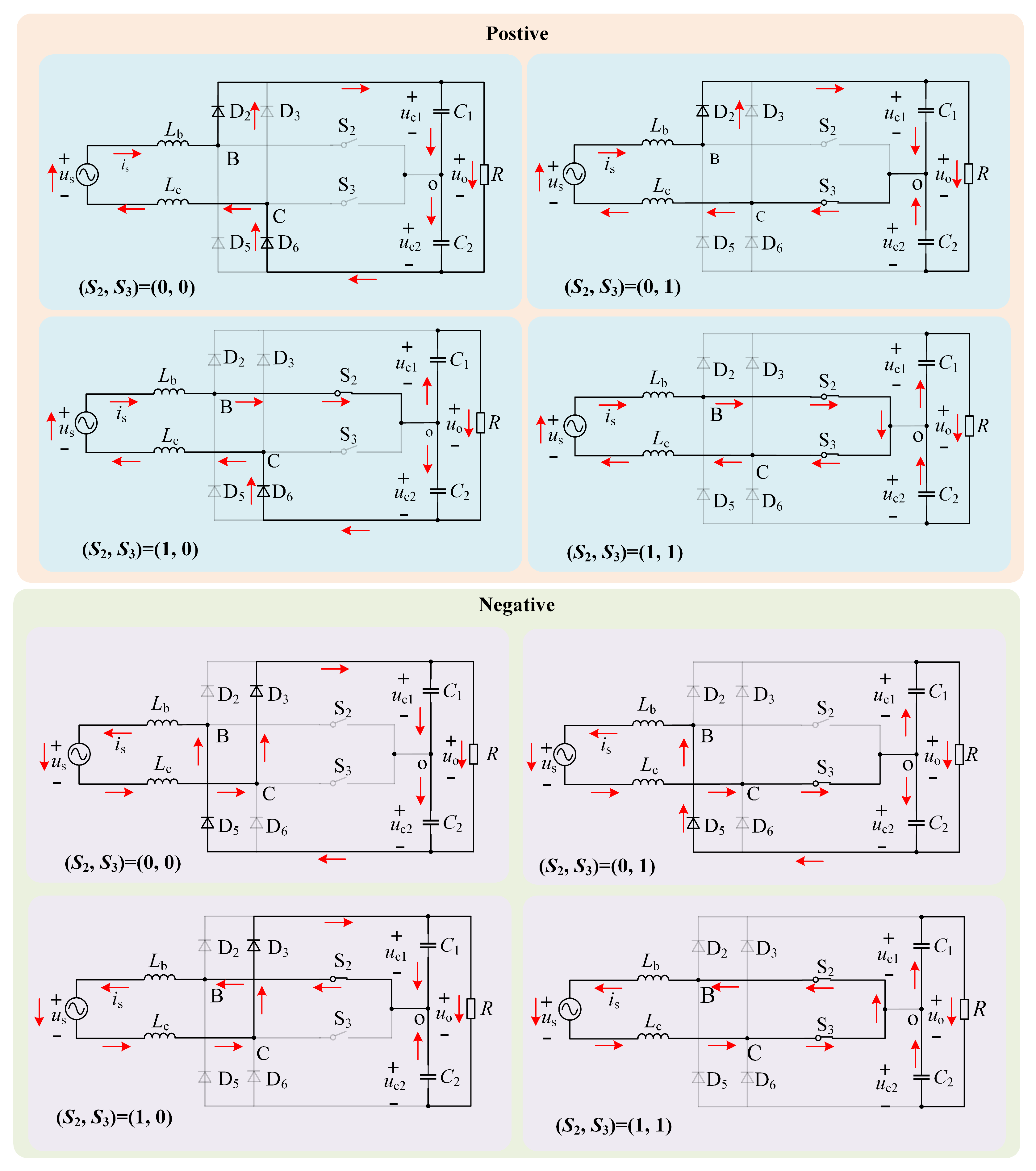
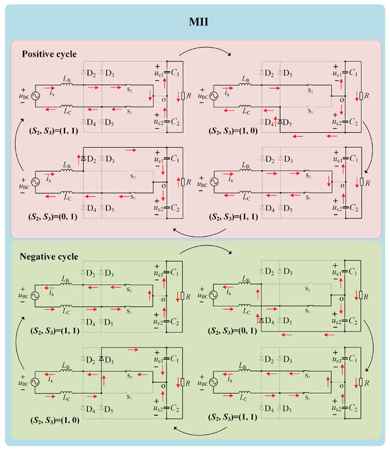
The operating states, based on the switching states of and , of the ECVR during the positive and negative half-cycles of are illustrated in Figure 4.
Figure 4.
Operating states.
During the positive half-cycle, the operating states are as follows:
- When , and are turned off, diodes and are conducting, inductors and are discharging, capacitors and are charging, and is positive.
- When , and are conducting; and are discharging; is charging, while is discharging; and is positive.
- When , and are conducting; and are discharging; is discharging, while is charging; and is positive.
- When , and are both conducting, diodes and are turned off, and are charging, and are discharging, and is positive.
During the negative half-cycle, the operating states are as follows:
- When , and are turned off, diodes and are conducting, inductors and are discharging, capacitors and are charging, and is negative.
- When , and are conducting; and are discharging; is discharging, while is charging; and is negative.
- When , and are conducting; and are discharging; is charging, while is discharging; and is negative.
- When , and are both conducting, diodes and are turned off, and are charging, and are discharging, and is negative.
Based on Figure 4, the voltage vectors of the three-phase Vienna rectifier under a phase-lack (phase A) fault are summarized in Table 1.
Table 1.
Voltage space vectors of the ECVR.
When and based on the previous analysis, the switching states and are completely symmetrical, with the inductors discharging in both cases. According to the operating principle of the boost converter, these states, together with the state, can be combined to construct a modulation method for the ECVR, enabling the inductors to complete a full charge–discharge cycle within a single switching period. Additionally, when , the inductors are also in the discharging stage. Similarly, a modulation method can be constructed based on the combination of and . These two modulation methods will be described in detail in the following sections.
Under normal operating conditions, the power factor . Let the effective values of the three-phase input phase voltage and phase current be U and I, respectively. The time-domain expressions of the three-phase phase voltages are as follows:
The time-domain expressions of the three-phase phase currents are
At this point, the total active power of the three-phase system is
After an open-phase fault occurs, the rectifier can only transmit energy through a single-phase circuit. To ensure stable power supply to the load, it is required that the power remains unchanged before and after the fault, and the unit power factor is maintained. Core Premise: After an open-phase fault, a fault-tolerant scheme using the line voltage of the remaining two phases for power supply is usually adopted (e.g., if phase a is open-circuited, the line voltage of phases b and c is used as the single-phase input voltage ). In a symmetric three-phase system, the relationship between the effective value of the line voltage () and the effective value of the phase voltage (U) is
This formula is a basic relationship in symmetric three-phase sinusoidal circuits. By combining the power conservation condition (i.e., ) and substituting into the equation, the expression for the effective value of the single-phase input current can be derived as follows:
Let the initial phase angle of the single-phase input voltage be . Then the time-domain expressions of the ECVR is as follows:
Input power and output power of the ECVR are defined as follows:
where represents the DC components of the output current , with = /. From (7),
Therefore, can be written as
The amplitude of the second-harmonic component of the voltage ripple is given as
3. Phase-Lack Modulation Method
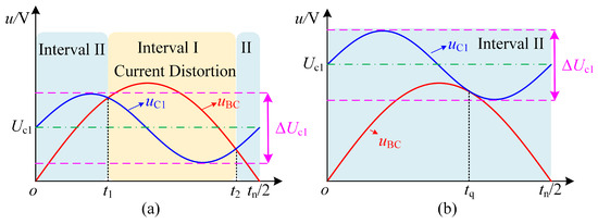
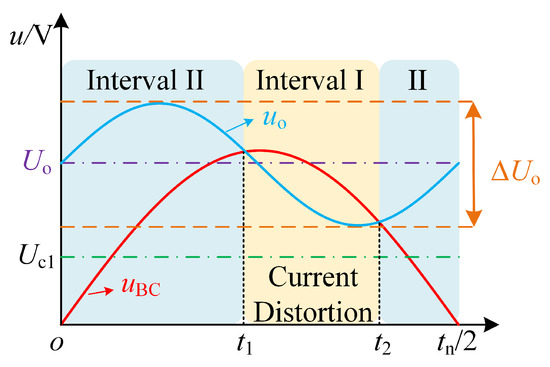
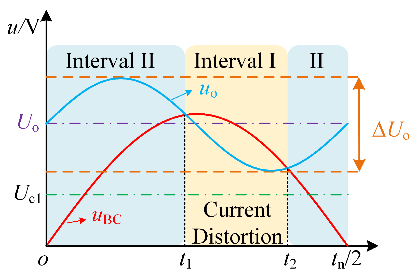
Based on (10), when phase-lack fault occurs in a three-phase Vienna rectifier, the output voltage exhibit a second-order pulsation. Moreover, as the output power increases or if the circuit parameters are improperly designed, the amplitude of the output voltage’s ripple also increases. This may lead to the ripple valley falling below the peak of the input voltage. Since the Vienna rectifier inherently operates as a boost converter, such conditions may trigger unintended switching actions, thereby disturbing the input current waveform and causing significant current distortion. For instance, in Figure 4, when or , the peak input voltage must remain lower than the voltage across or (both of which are necessarily below the output voltage), making such situations prone to occur. The schematic diagram is presented in Figure 5. denotes the amplitude of the second-harmonic ripple of .
Figure 5.
Input current distortion interval: (a) ; (b) .
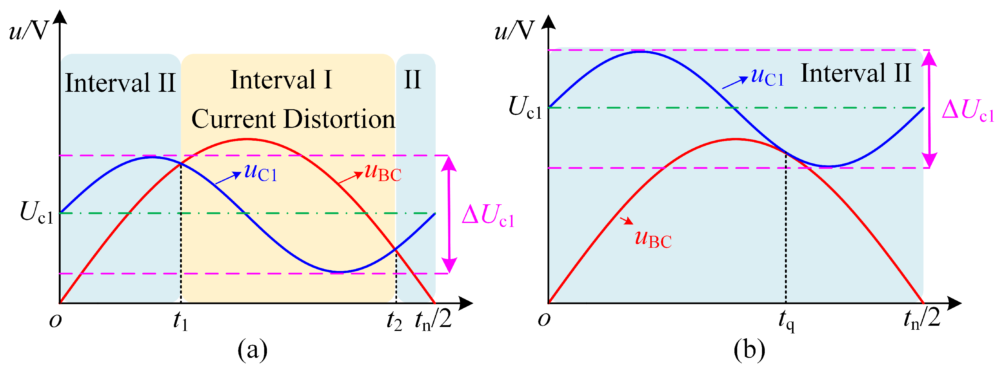
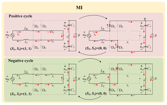
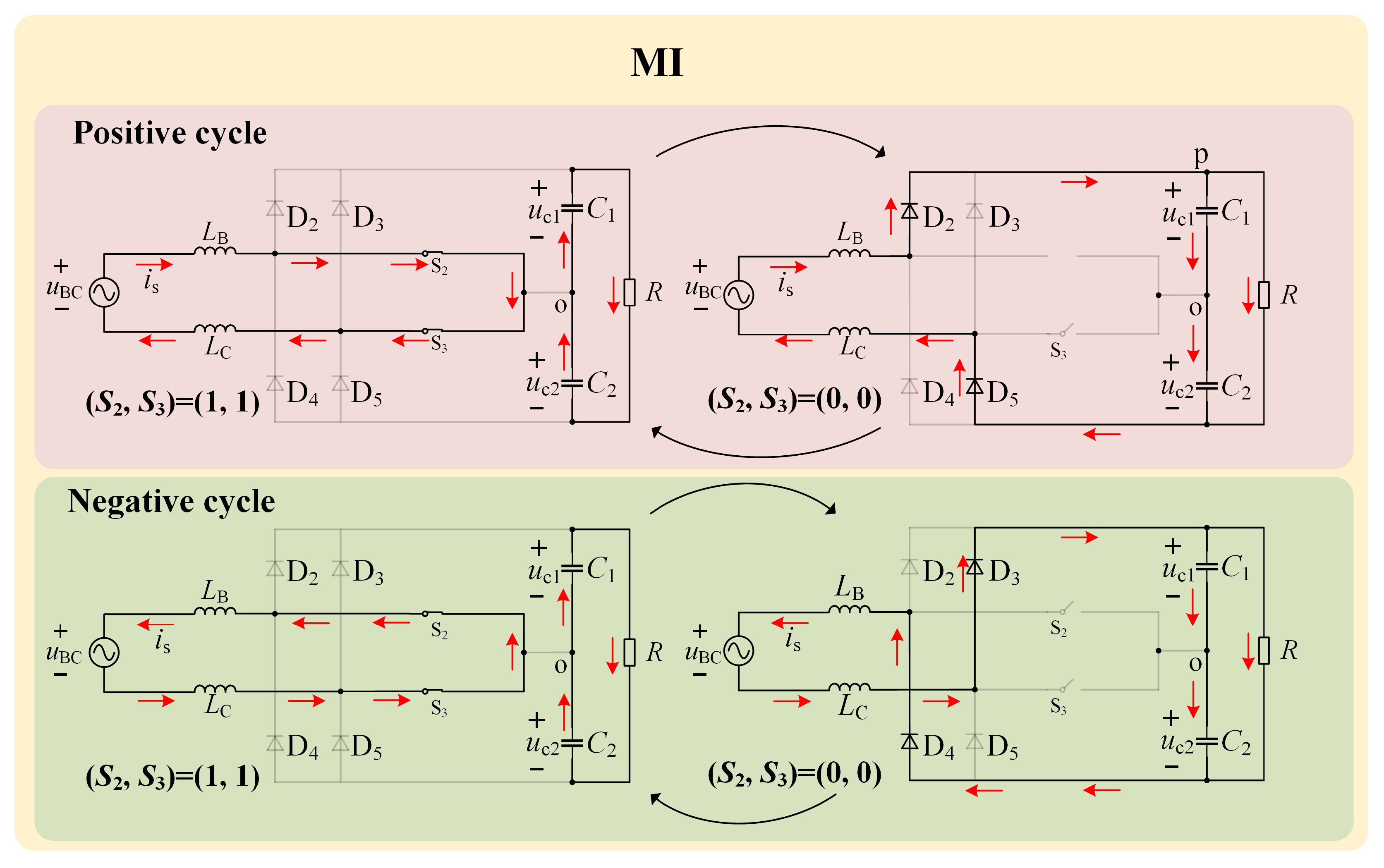
As illustrated in Figure 5a, the input voltage is divided into two operating intervals according to the capacitor voltage . When , the system operates in interval II, corresponding to the time range or . When , it enters interval I, covering . Within interval I, the relationship between and no longer satisfies the intrinsic voltage constraint of the Vienna rectifier, resulting in noticeable input current distortion. As increases, the distortion interval gradually narrows. Once the output voltage’s ripple becomes tangent to the input voltage at , the distortion region completely disappears, as depicted in Figure 5b. According to the preceding analysis, within interval II, the modulation can be implemented by alternately selecting the switching states and , as illustrated in Figure 6. The red arrows in the figure indicate the direction of current flow, the below has the same meaning. Hereafter, this modulation method is referred to as MI for brevity.
Figure 6.
Modulation method in interval I.
According to Figure 6, under the MI modulation scheme, the ECVR operates in only two distinct states: When , and are charged. In the alternative operating state, when , and are discharged. As a result, the operating mechanism is identical to that of a conventional boost converter. Therefore, the input voltage must be less than the output voltage , thus meeting the condition . As is also higher than (or ), interval I in Figure 5a becomes narrower, as depicted in Figure 7.
Figure 7.
Input current distortion interval with MI.
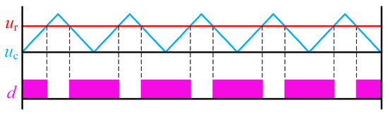
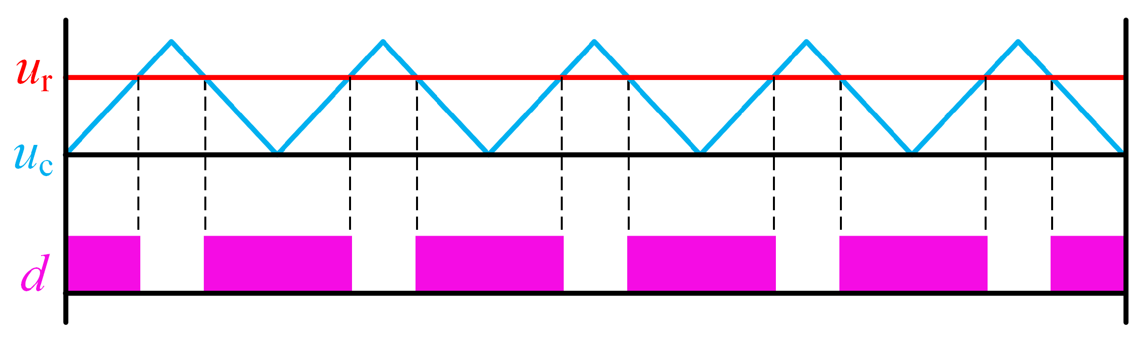
It can be observed from Figure 7 that interval I occupies a shorter period than in Figure 5a. Therefore, the MII method can effectively mitigate the impact of output voltage ripples caused by a phase-lack fault on the input current, thereby improving the waveform quality of the input current under phase-lack conditions. The implementation of MI is shown in Figure 8.
Figure 8.
Implementation of the MI modulation scheme.
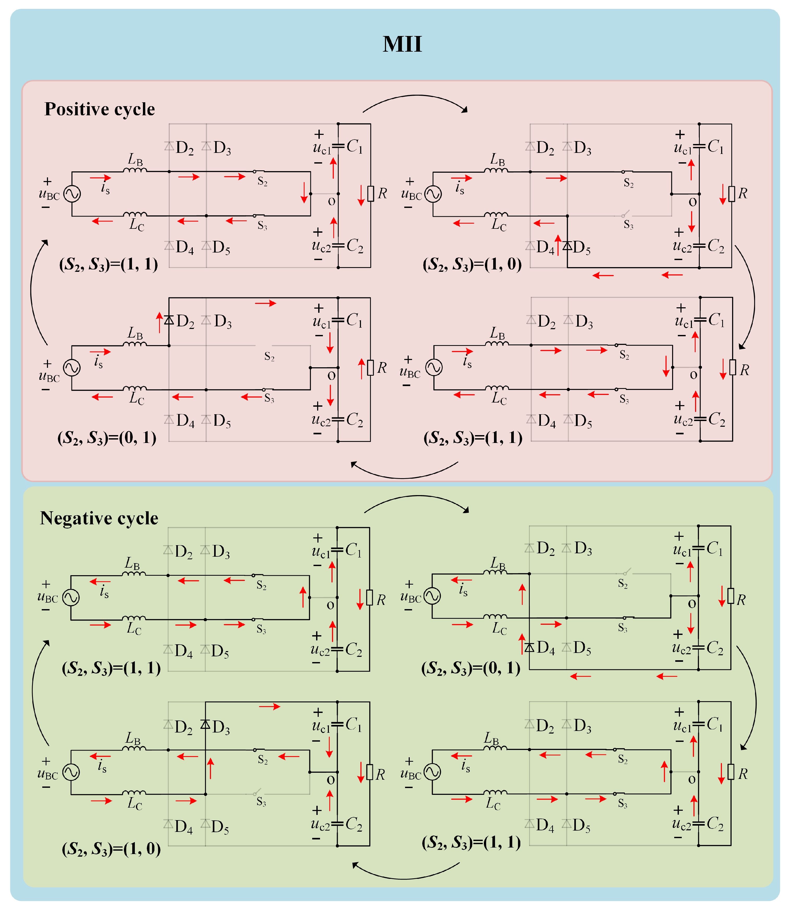
Over several switching cycles, as displayed in Figure 8, the modulation waveform can be approximated as a straight line. The PWM signal is generated via a comparison with the carrier. When (the modulation signal), the PWM output is high; otherwise, it is low. As shown in Figure 6, and switch simultaneously, so their PWM signals are identical. From Figure 4, it can be seen that the modulation method composed of or and requires (or to be greater than . Following this, compared with MI, this method requires a higher output voltage () and can therefore be applied when , i.e., in region II. This modulation method, referred to as MII in this paper and illustrated in Figure 9, builds on the approach described above.
Figure 9.
Modulation method in interval II.
By comparing Figure 9 with Figure 7, it is evident that, unlike MI, MII involves only a single switching action per cycle, which effectively reduces switching losses. Moreover, since is lower during the inductor discharging phase, the input current ripple under MII is also diminished. Let the change in the input current during the inductor charging phase be . Using the volt-second characteristic of the inductor, can be calculated separately for the MI and MII modes.
The variation in the input current during the discharging stage is denoted as . Since the inductor’s current variation process is identical in both operating modes during this stage, its input current ripples are the same, as shown in (12).
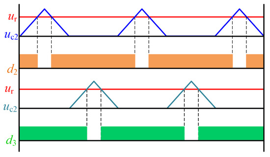
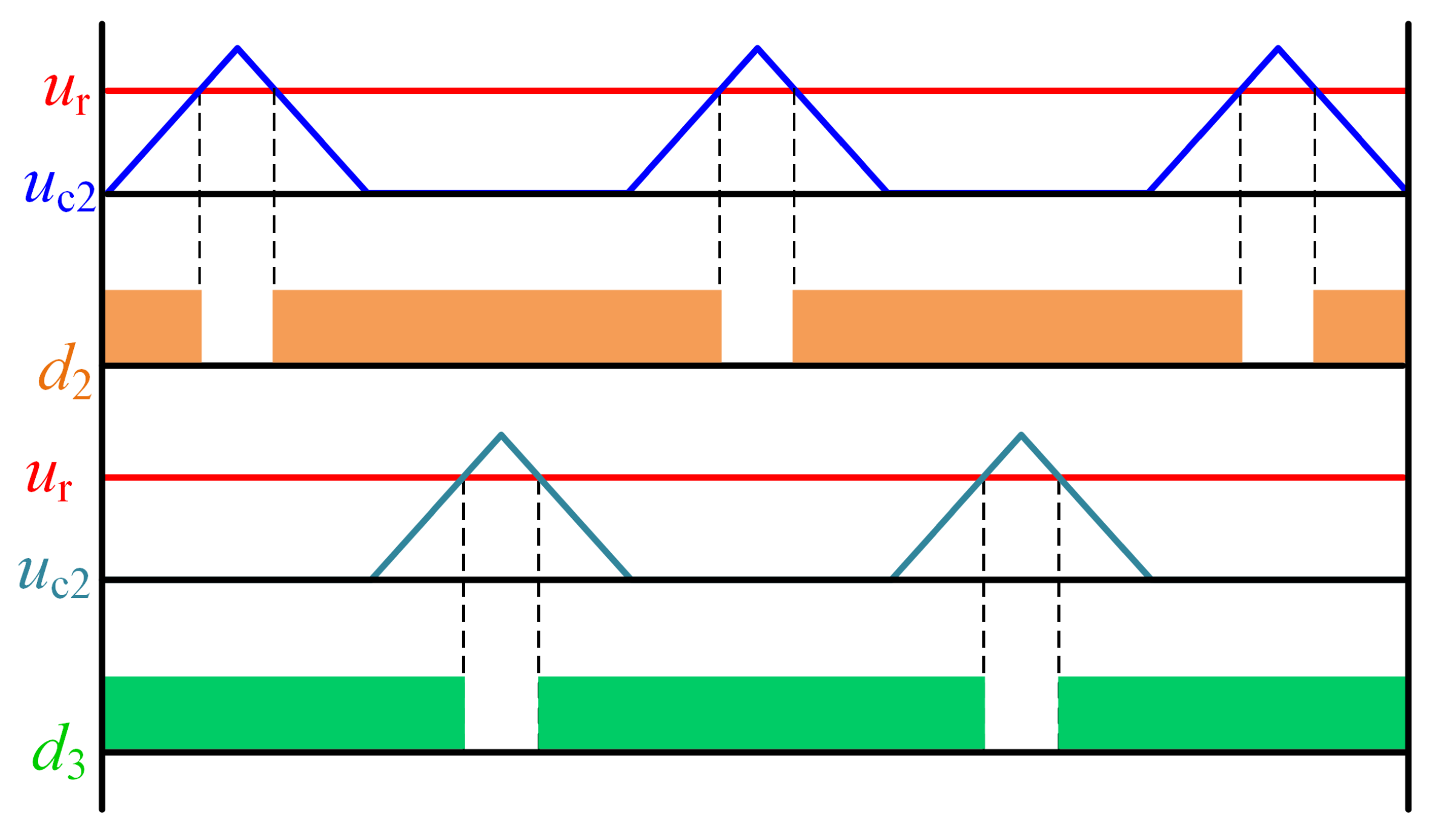
By combining (11) and (12), it can be observed that during the inductor discharge phase, the input current’s increment is larger under MI, whereas both modes exhibit identical charging increments. Consequently, the ECVR’s input current ripple is more pronounced under MI. The implementation of MI is shown in Figure 10. The modulation signal is compared with the carriers and , and the resulting PWM signals are applied to and , respectively.
Figure 10.
Implementation of the MII modulation scheme.
In summary, when a single-phase fault occurs, The output voltage of the three-phase Vienna rectifier exhibits a double-frequency ripple, distorting the input current. The proposed modulation approach selects the appropriate modulation method based on the relative magnitudes of the input and output voltages, thereby effectively improving the quality of the input current waveform, as presented in Table 2.
Table 2.
Proposed modulation strategy.
4. Phase-Lack Control
4.1. Phase-Lack Mathematical Model
In Figure 9, the states and are symmetrical. Therefore, the equivalent circuit of the ECVR under MI and II is presented in Figure 11.
Figure 11.
Equivalent circuits of the ECVR: (a) MI; (b) MII.
From Figure 11a, the state-space equation under MI can be expressed as
4.2. Controller Design
The Vienna rectifier is commonly regulated using a dual-loop control strategy, combining voltage and current loops based on average current control The relevant cited content has been deleted in the revised draft [34]. Based on the small-signal model in (15), the corresponding control block diagram of the ECVR is shown in Figure 12.
Figure 12.
Control block diagram.
In Figure 12, and represent the voltage outer-loop and current inner-loop controllers, respectively. and indicate the reference values for the output voltage and input current, respectively, while signifies the voltage across the inductor.
4.2.1. Inner Current Loop
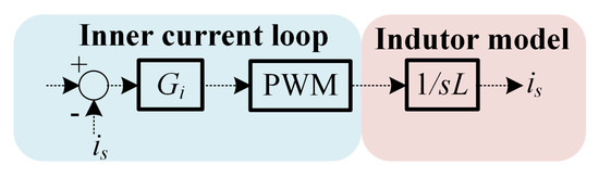
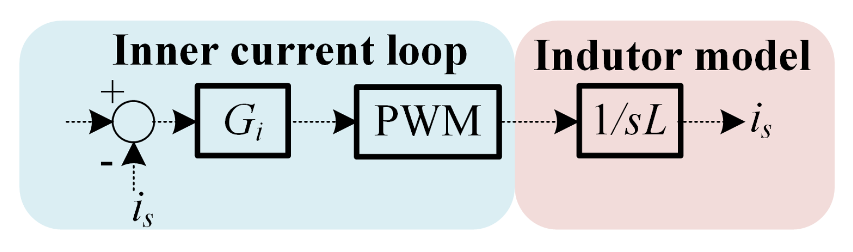
The simplified control block diagram of the inner current loop is shown in Figure 13.
Figure 13.
Block diagram of Inner current loop.
The inner current loop commonly employs a quasi-proportional-resonant controller. As a result, this enables zero steady-state error regulation for AC signals, as expressed in (16).
where is the proportional gain, is the resonant gain, represents the cutoff angular frequency, and denotes the resonant angular frequency corresponding to the 50 Hz grid voltage.
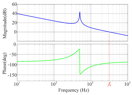
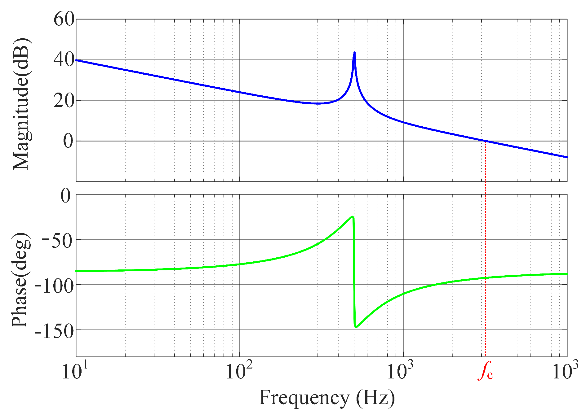
Let the PWM gain be unity, and let the controller parameters be set as , , , and . Then, the open-loop Bode diagram of the inner current loop is illustrated in Figure 14.
Figure 14.
Bode plot of the open-loop transfer function for the inner current loop.
In Figure 14, the current inner-loop transfer function exhibits a pronounced gain near the resonant frequency. At the crossover frequency , the phase reaches , yielding a phase margin of , which is greater than the conventional stability threshold of . Hence, the system is capable of maintaining stable regulation of the input current with zero steady-state error.
4.2.2. Outer Voltage Loop
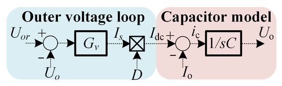
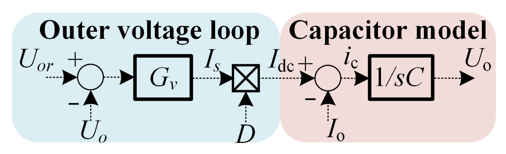
Figure 15 depicts the simplified control block diagram of the outer voltage loop when the current inner loop achieving zero steady-state error regulation.
Figure 15.
Outer voltage loop.
Since the controlled variable is a DC quantity, according to the internal model principle, the voltage outer loop can be implemented using a PI controller. From (8), the following relationship can be derived:
Neglecting the influence of output current disturbances, the closed-loop transfer function of the outer voltage loop is expressed as in (18).
Here, and denote the proportional and integral gains of the PI controller, respectively, . According to the standard second-order transfer function, the controller parameters can be obtained as
where is the damping ratio.
4.3. DC Capacitor Voltage-Balancing Control
Due to hardware tolerances and other variations, the DC capacitor voltages may become unbalanced. Therefore, the Vienna rectifier typically requires DC-link capacitor voltage-balancing control.
Let the voltage difference between and be denoted as ; then
Hence, the solution is
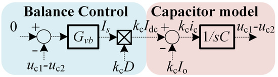
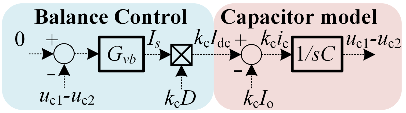
Therefore, by selecting as the control variable and setting its reference value to zero, we can balance and . The implementation method is shown in (22). The control block diagram is depicted in Figure 16.
Figure 16.
Balance control loop.
Based on Figure 16, .
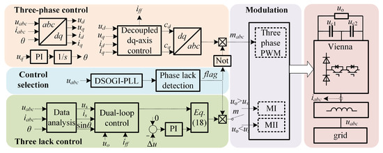
In summary, the phase-lack control strategy of the three-phase Vienna rectifier is shown in Figure 17. The DSOGI-PLL method is employed to determine whether a phase-lack fault has occurred [35]. Based on this detection, the controller dynamically selects the appropriate control mode. A flag signal serves as the phase-lack indicator: when a phase-lack fault is detected, flag = 1, activating the fault-tolerant control scheme. Conversely, when flag = 0, the system operates under the normal three-phase decoupling control strategy. There is no three-phase circuit under the phase-lack condition (taking phase A as an example). The voltage sampled from phase B and phase C is half of the line-to-line voltage, while the sampled voltage of phase A is zero.
where is the effective value of the input phase voltage. At this point, the positive and negative sequence voltage components on the d-axis are as follows:
Figure 17.
Phase-lack control strategy.
To determine a phase-lack fault, it is identified when the negative sequence component exceeds 20 V and the positive sequence component is less than 1.5 times [29].
After an open-circuit fault occurs, to maintain constant output power and voltage, the system needs to switch from the normal operating condition to the fault-tolerant operating condition. However, restricted by the inherent slow response characteristic of the voltage outer loop, the dynamic transition process of the condition switch is relatively long. Therefore, it is necessary to introduce a feedforward compensation term to improve the response speed. The designed feedforward compensation term for the current inner loop is given by
where is the steady-state line current before the open-circuit fault, denotes the reference output voltage, and is the actual output voltage. When the system is stable, the output voltage deviation approaches zero, and the feedforward compensation term in (25) also tends to zero accordingly. At this point, the system can maintain stable operation by relying solely on the closed-loop control of the current inner loop.
5. Simulation
In this section, a three-phase Vienna rectifier model is established in MATLAB2016/Simulink to verify the effectiveness of the proposed phase-loss control strategy. The simulation parameters are summarized in Table 3.
Table 3.
Simulation parameters.
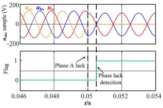
Figure 18 shows the simulation of phase-lack detection. An A-phase-lack fault occurs at . At this moment, , while and have opposite directions and are both set to 133 V. After a quarter of one fundamental period, the phase-lack detection module is triggered, and the flag signal changes from 0 to 1, indicating that the A-phase-lack fault has been successfully detected.
Figure 18.
Phase-lack detection.
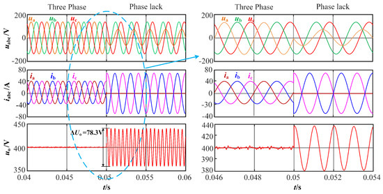
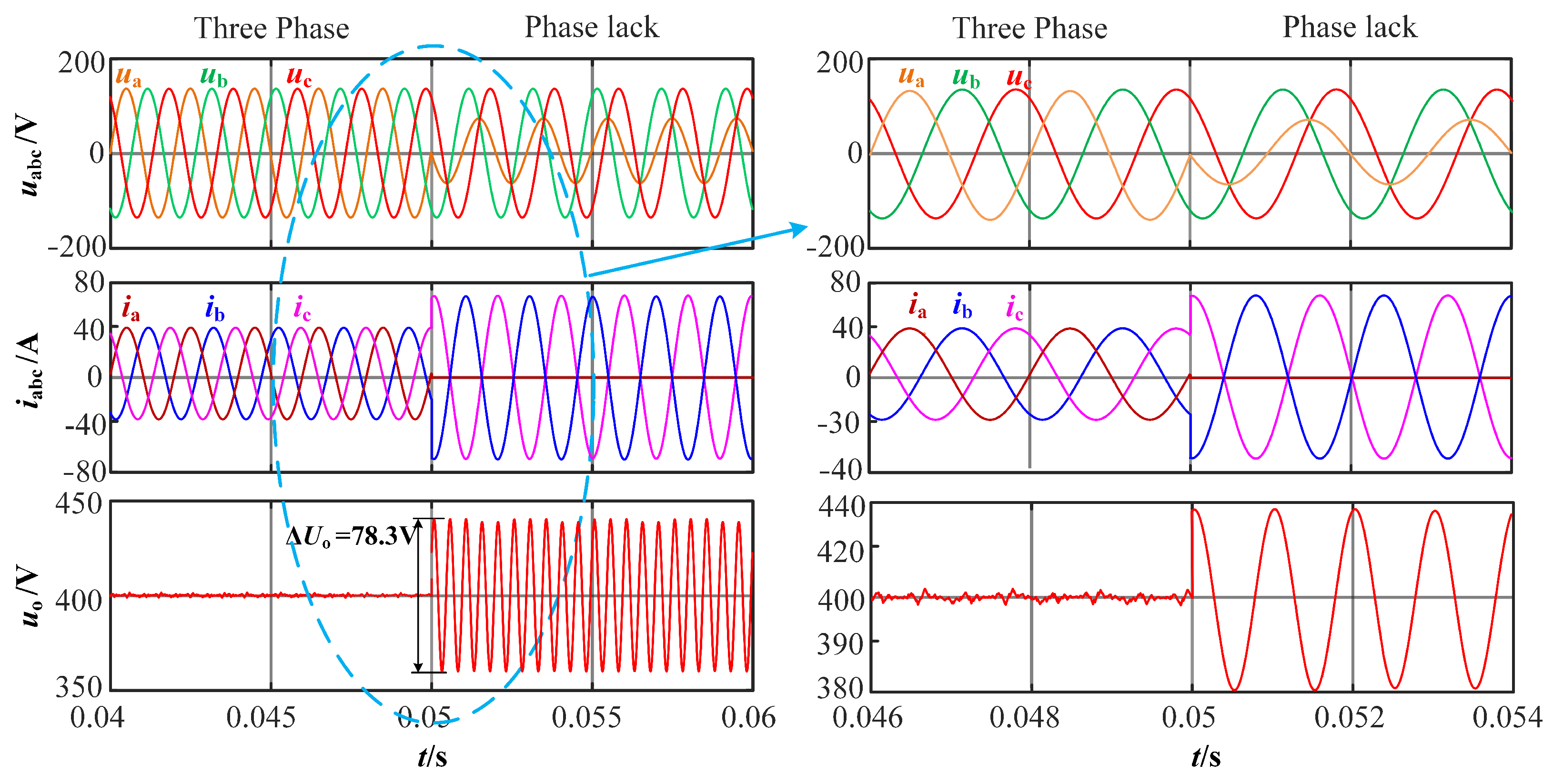
Figure 19 shows the simulation results for the input voltage, input current, and output voltage of the three-phase Vienna rectifier during a phase-lack fault under the proposed phase-lack control strategy. Before , the Vienna rectifier operates under normal three-phase conditions, while after , it enters the phase-lack state.
Figure 19.
, , and under the proposed phase-lack control strategy.
Under normal operating conditions, the three-phase currents are in phase with the corresponding voltages , with a phase current amplitude of 37.2 A. The DC-link voltage remains nearly constant, with no low-frequency ripple observed. Under the phase-lack condition, the voltages and retain their original characteristics without any changes, while does not drop to zero but instead undergoes a phase shift and amplitude reduction, which are attributed to measurement-related factors. As can be seen from the enlarged view of Figure 19, the proposed phase-lack control strategy achieves an almost-zero dynamic adjustment time, exhibiting excellent control performance. After the fault occurs, the phase current decreases to zero, whereas and feature equal amplitudes but with opposite directions.
It can be observed from the simulation that the amplitudes of and increase to approximately , which is about times that under normal three-phase operating conditions, and the output power remains constant before and after the phase-lack fault. The output voltage presents a second-harmonic ripple with an amplitude of 78.3 V, which is in excellent agreement with the theoretical result derived from Equation (10).
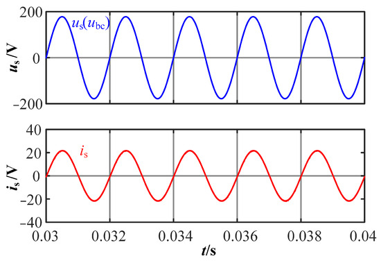
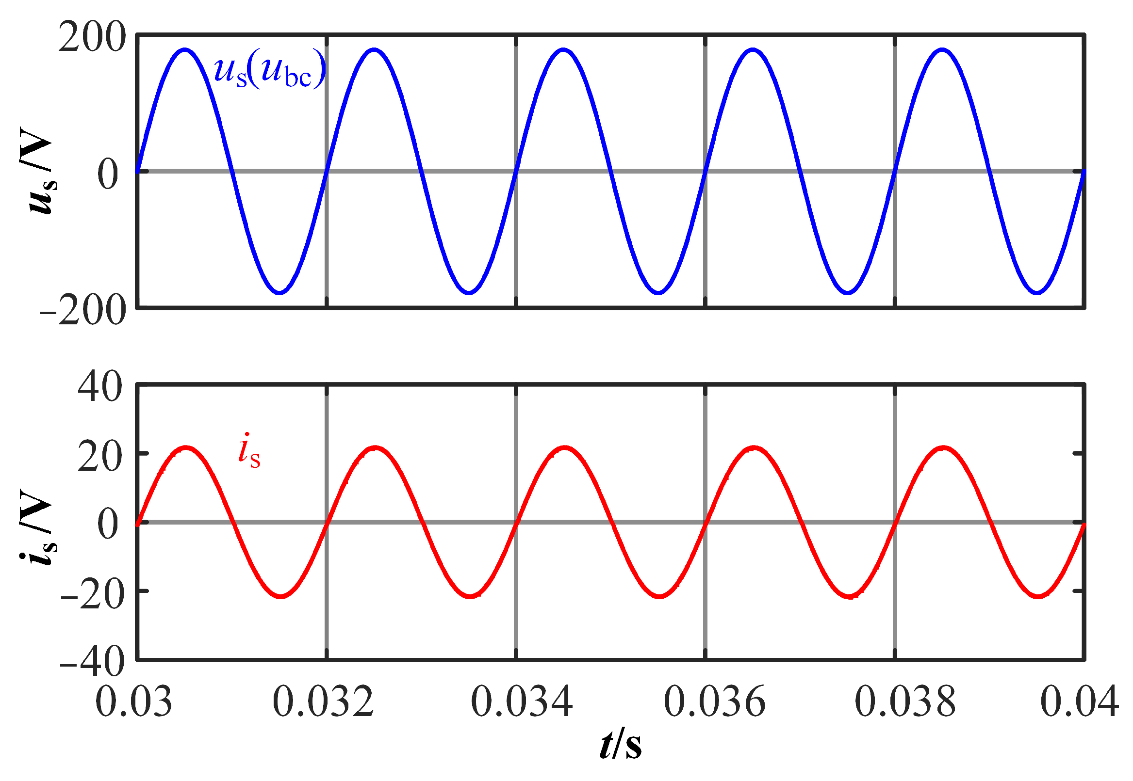
Under the proposed phase-lack control strategy, the three-phase Vienna rectifier operates as a single-phase Vienna converter by using the DC-line voltage as its input after the phase-lack fault, as illustrated in Figure 20. remains in phase with , indicating that the proposed control strategy can achieve effective power factor correction under single-phase operation.
Figure 20.
and under the proposed phase-lack control strategy.
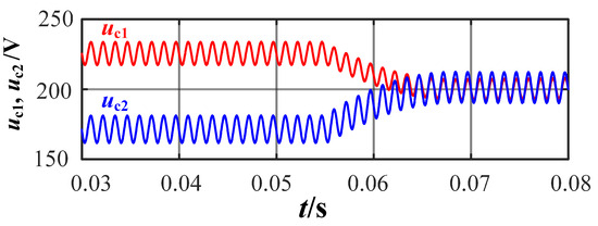
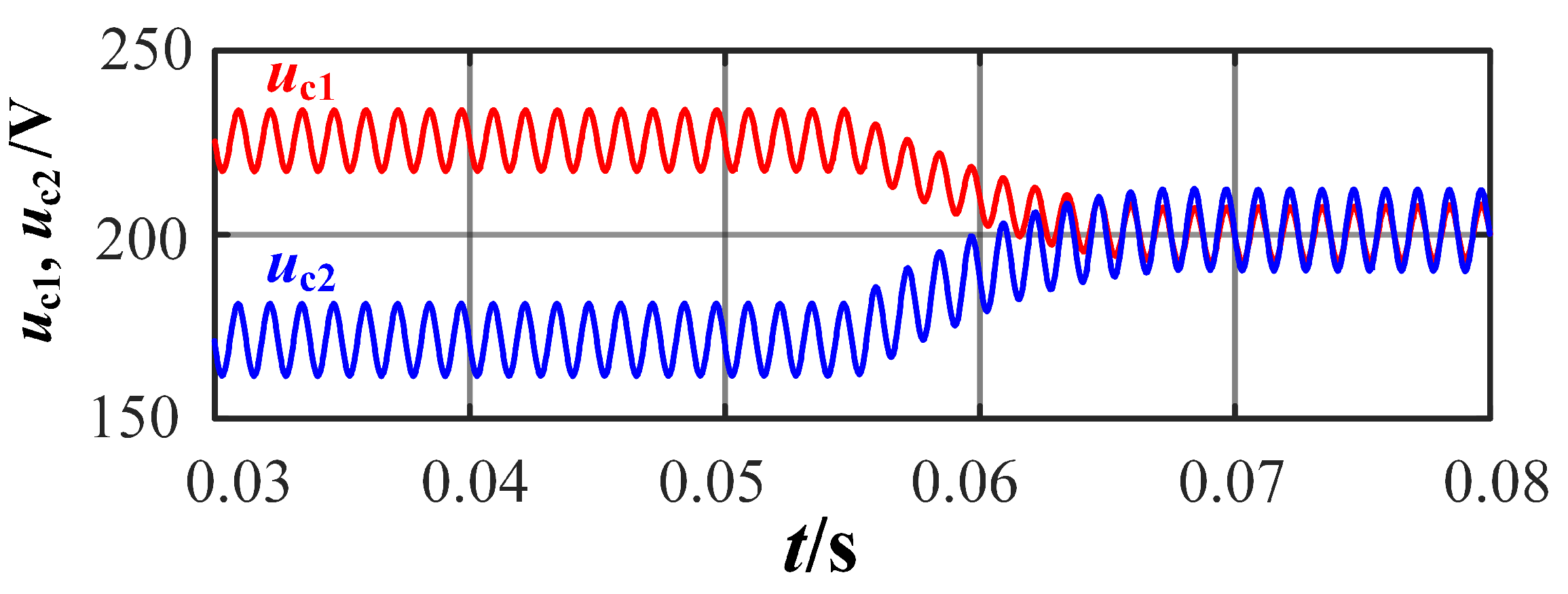
As shown in Figure 21, after a phase-lack fault occurs, the DC-link capacitors exhibit a voltage imbalance, that is, . The average value of is 239 V, with a ripple amplitude of 21.3 V, while has an average value of 162 V and a ripple of 22.1 V. The ripple magnitudes of the two capacitors are nearly identical. When the proposed phase-lack control method is activated at , the two capacitor voltages gradually converge after a short regulation period and eventually stabilize around 200 V, corresponding to half of the output voltage.
Figure 21.
and under the proposed phase-lack control strategy.
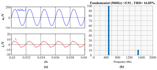
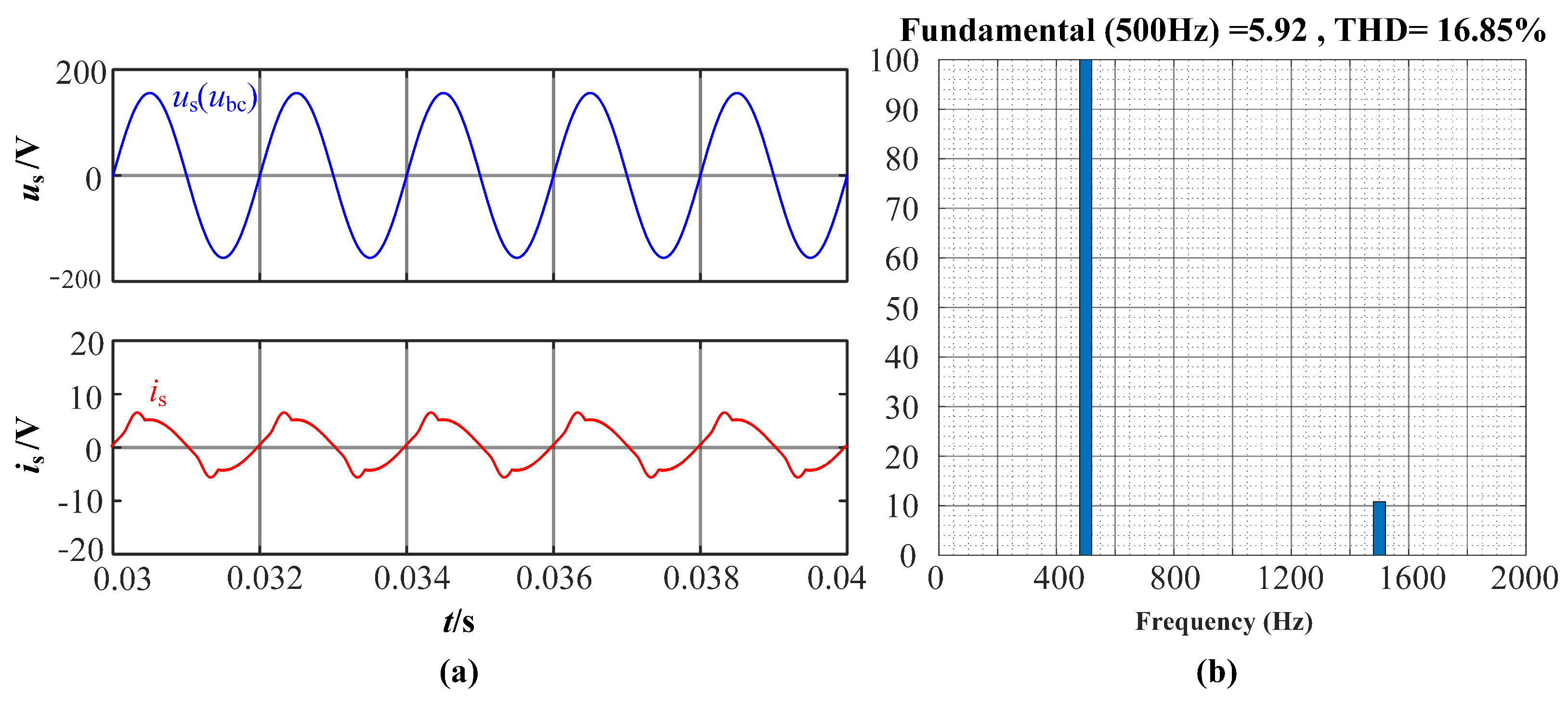
When is set to 200 V, the input current exhibits noticeable distortion, as depicted in Figure 22a, indicating deterioration in . The FFT analysis of the input current is presented in Figure 22b, where total harmonic distortion (THD) of reaches 16.85%, with the third harmonic being dominant. The simulation results when MII is adopted are presented in Figure 23.
Figure 22.
without MI at = 200 V: (a) and ; (b) FFT of .
Figure 23.
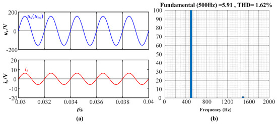
with MI at = 200 V: (a) and ; (b) FFT of .
As shown in Figure 23a, when the MII control strategy is applied, the input current maintains a sinusoidal waveform with negligible distortion. Meanwhile, Figure 23b illustrates that the third-harmonic component is significantly suppressed, resulting in the THD being reduced to 1.62%. Simulation results demonstrate that the proposed phase-lack control strategy can rapidly detect the phase-lack fault and smoothly transition the Vienna rectifier to single-phase operation. The strategy effectively maintains power factor correction performance and a stable DC output during faults, thereby enhancing the system’s fault tolerance and operational reliability.
6. Experiment
After completing simulation analysis and verifying its feasibility, we further perform experiments to verify and compare the simulation results. The power of the experimental platform is 5 kW, with a rated output current/voltage of 12.5 A/400 V, and the input voltage is . Table 4 lists the materials used in the experiment. It is worth noting that each powered semiconductor device consists of two devices connected in parallel to enhance current capability, whereas the remaining components are implemented as single devices.
Table 4.
Experiment parameters.
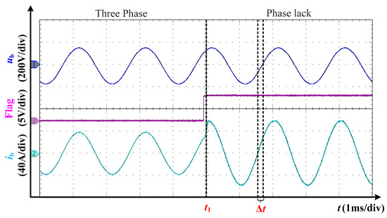
Figure 24 presents the experimental results of , , and under the proposed phase-lack control strategy. When the phase-lack flag , it indicates that the system has detected a fault. At , under the proposed control strategy, the dynamic transient process of the system is almost negligible. It can be observed from the waveforms that a zero-crossing time difference exists between and , denoted as . At the operating frequency of , the corresponding phase difference can be calculated as
Figure 24.
Experimental results: , , , and under the proposed phase-lack control strategy.
Therefore, the phase of leads that of by approximately . Consequently, the input current remains in phase with the line voltage , confirming that the PFC function is maintained under the phase-lack condition. The amplitude of increases from 38.6 A to 65.7 A, which is approximately times higher than previously described. Therefore, constant power operation is achieved under the phase-lack condition.
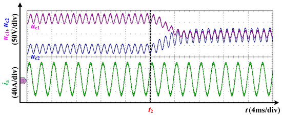
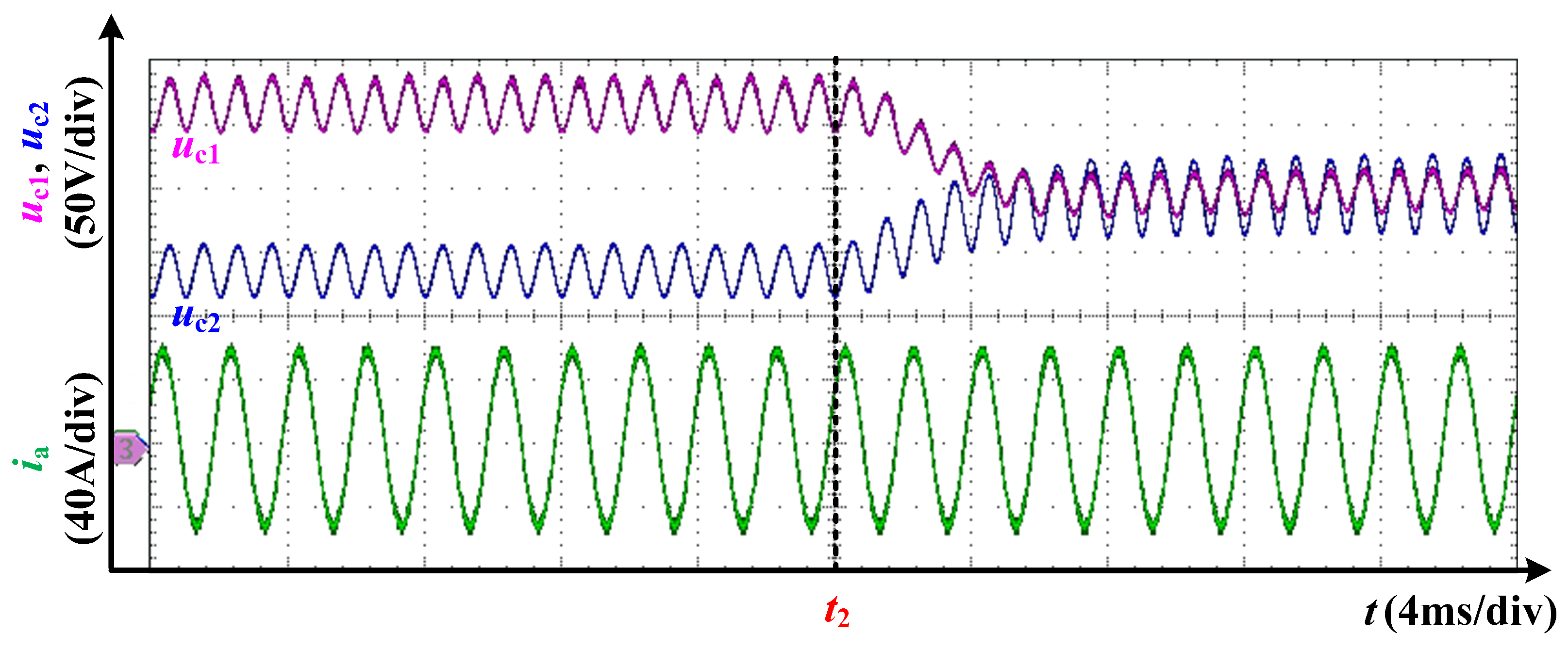
The experimental results of and are presented in Figure 25. In this experiment, the capacitances are set to and . Under the proposed phase-loss control strategy, after a short transient process, and converge and overlap, with average values of approximately . Moreover, both capacitor voltages exhibit a double-frequency ripple, which results in a second-order ripple component in the output voltage (). After the capacitor voltages are balanced, the ripple amplitudes of and are and , respectively. Consequently, the ripple voltage of is . The discrepancy between the experimental and simulation results arises from the difference in capacitance values, since the equivalent capacitance in the simulation is , whereas the equivalent capacitance in the experiment is 33.3 .
Figure 25.
Experimental results: and under the proposed phase-lack control strategy.
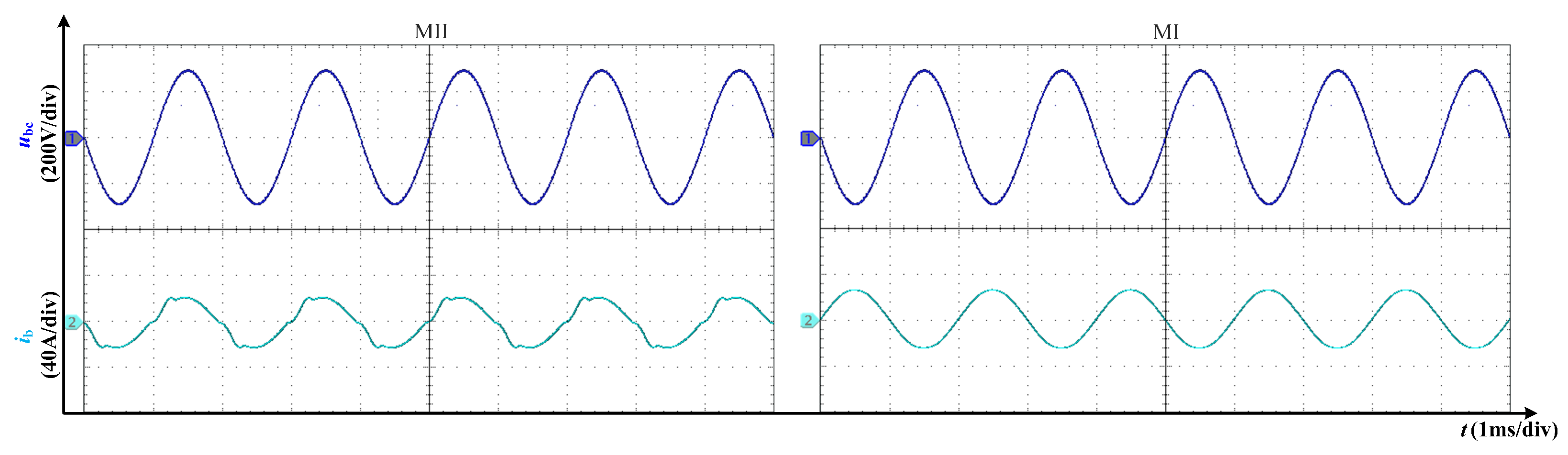
Figure 26 shows the experimental results of the input current under MI and MII when . It can be observed that, under the MII strategy, exhibits noticeable distortion, whereas under the MI strategy, presents a well-shaped sinusoidal waveform. In both cases, remains in phase with the line voltage . The experimental results are in good agreement with the simulation results.
Figure 26.
Experimental results: under the MI and MI strategies when = 200 V.
7. Conclusions
This paper proposes a phase-lack control strategy for the three-phase Vienna rectifier applied in aerospace power systems. The proposed strategy enables a smooth transition from three-phase operation to single-phase operation under the phase-lack conditions while maintaining low total harmonic distortion and power factor correction, as well as a stable DC voltage output in single-phase mode. However, due to the inherent characteristics of single-phase power transfer, the DC output voltage exhibits increased low-frequency ripples. Future work will focus on utilizing the idle bridge arm during phase-lack operation to mitigate this low-frequency ripple through control reconfiguration or energy compensation, thereby improving the system’s power quality and dynamic performance.
Author Contributions
Conceptualization, S.Z.; validation, Y.C. and X.Y.; formal analysis, M.H. and K.F.; investigation, Z.W. and Z.L. All authors have read and agreed to the published version of the manuscript.
Funding
This project was supported by China Southern Power Grid Technology Project (Project Number: GZKJXM20240142, 060000KC24040031).
Institutional Review Board Statement
Not applicable.
Informed Consent Statement
Not applicable.
Data Availability Statement
The original contributions presented in the study are included in the article. Further inquiries can be directed to the corresponding author.
Conflicts of Interest
Authors Song Zhang, Yongxiang Cai, Xinyu You, Mingjun He, Ke Fan, Zhuoyue Wang was employed by the company Electric Power Scientific Research Institute, Guizhou Power Grid Co., Ltd. The remaining authors declare that the research was conducted in the absence of any commercial or financial relationships that could be construed as a potential conflict of interest.
References
- Catalbas, N.; Pakfiliz, A.G.; Soysal, G. Multilevel Aircraft-Inverter Design Based on Wavelet PWM for More Electric Aircraft. Energies 2024, 17, 2054. [Google Scholar] [CrossRef] [Scilit]
- Thonemann, N.; Pierrat, E.; Dudka, K.M.; Saavedra-Rubio, K.; Tromer Dragsdahl, A.L.S.; Laurent, A. Towards sustainable regional aviation: Environmental potential of hybrid-electric aircraft and alternative fuels. Sustain. Prod. Consum. 2024, 45, 371–385. [Google Scholar] [CrossRef] [Scilit]
- Ye, H.; Li, Z.; Fan, Q.; Cai, Y.; Pang, L. Exploratory Study on the Construction of Carbon Accounting and Dual-Control Mechanism for Grid Enterprises Under the Carbon Peak and Carbon Neutrality. Power Syst. Big Data 2025, 28, 1–12. [Google Scholar]
- Yu, W.; Xie, D.; Xu, Y.; Ming, D.; Ao, D.; Liu, S.; You, W. Research on the Load Characteristics and Demand Response Market of Provincial Power Grid. Power Syst. Big Data 2025, 28, 18–26. [Google Scholar]
- Benzaquen, J.; He, J.B.; Mirafzal, B. Toward more electric powertrains in aircraft: Technical challenges and advancements. CES Trans. Electr. Mach. Syst. 2021, 5, 177–193. [Google Scholar] [CrossRef] [Scilit]
- Shirai, R.; Wada, K. EMI Noise Mitigation for Multiple Inverters of Hybrid Electric Aircraft Propulsion Systems. In Proceedings of the 2025 IEEE/AIAA Transportation Electrification Conference and Electric Aircraft Technologies Symposium (ITEC+EATS), Anaheim, CA, USA, 18–20 June 2025; pp. 1–5. [Google Scholar]
- Peng, Q.; Sun, J.; Yang, J.; Buticchi, G.; Tan, N.M.; Guenter, S.; Wheeler, P. Harmonic Distortion Analysis of an eGPU-Fed Aircraft EPDS with Phase-Shifted Carrier PWM. In Proceedings of the 2024 IEEE 15th International Symposium on Power Electronics for Distributed Generation Systems (PEDG), Luxembourg, 23–26 June 2024; pp. 1–6. [Google Scholar]
- Ren, X.; Zhou, Y.; Guo, Z.; Wu, Y.; Zhang, Z.; Chen, Q. Analysis and improvement of capacitance effects in 360–800 Hz variable on-time controlled CRM Boost PFC converters. IEEE Trans. Power Electron. 2020, 35, 7480–7491. [Google Scholar] [CrossRef] [Scilit]
- Xiao, H.; Su, X.; Guo, Q. Predictive current control of three-phase Vienna rectifier without grid voltage sensors. Trans. China Electrotech. Soc. 2021, 36, 1304–1312. [Google Scholar]
- Lai, L.; Zhang, B.; Lin, J. PT-Symmetric CLLC Coreless Transformer With Magnetic Potential Balance. IEEE Trans. Ind. Electron. 2024, 71, 12436–12446. [Google Scholar] [CrossRef] [Scilit]
- Yang, C.; Zhang, F.; Cheng, L.; Zhang, Z.; Wang, T. A fault-tolerant control method for improving input current half-wave symmetry under single-switch open-circuit fault of front-end Vienna rectifier in more-electric aircraft. IEEE Trans. Power Electron. 2025, 40, 2170–2183. [Google Scholar] [CrossRef] [Scilit]
- Liu, X.; Bao, P.; Lei, K.; Feng, Y.; Zhang, X. Vienna-based hybrid three-phase step-down PFC rectifier for more electric aircraft. IEEE Trans. Transp. Electrific. 2025, 11, 2181–2192. [Google Scholar] [CrossRef] [Scilit]
- Pei, Y.; Tang, Y.; Hu, M.; Zhang, Z.; Yao, F. Switching loss-reduced space-vector DPWM for three-phase Vienna rectifier considering neutral-point voltage fluctuation. IEEE Trans. Power Electron. 2024, 39, 16231–16241. [Google Scholar] [CrossRef] [Scilit]
- Zhang, Z.; Li, B.; Fu, Z.; Wang, G.; Wang, Q.; Ding, D.; Zhang, G.; Xu, D. Duty cycle prediction control based DPWM strategy for electrolytic capacitorless Vienna rectifier. IEEE Trans. Ind. Electron. 2025, 72, 1170–1180. [Google Scholar] [CrossRef] [Scilit]
- Go, H.-U.; Lee, S.-H.; Kim, M.-S.; Zhou, G.; Park, S.-J.; Wang, Y. Three-phase Vienna rectifier interval control strategy to improve light load performance. IEEE J. Emerg. Sel. Top. Power Electron. 2025, 13, 5867–5876. [Google Scholar] [CrossRef] [Scilit]
- Zhang, Z.; Zhang, G.; Liu, W.; Hu, B.; Wang, J.; Wang, G.; Xu, D. Negative sequence current regulation based power control strategy for Vienna rectifier under unbalanced grid voltage dips. IEEE Trans. Ind. Electron. 2024, 71, 1170–1180. [Google Scholar] [CrossRef] [Scilit]
- DO-160G-2010; Environmental Conditions and Test Procedures for Aircraft Equipment. Radio Technical Commission for Aeronautics: Washington, DC, USA, 2010.
- Tran, V.T.; Nguyen, K.M.; Do, D.T.; Nguyen-Phan, A.-T. Open-circuit fault-tolerant method for three-level T-type inverter with voltage gain enhancing. IEEE Trans. Circuits Syst. II Exp. Briefs 2024, 71, 927–931. [Google Scholar] [CrossRef] [Scilit]
- Xu, S.; Zhang, J.; Hang, J. Investigation of a fault-tolerant three-level T-type inverter system. IEEE Trans. Ind. Appl. 2017, 53, 4613–4623. [Google Scholar] [CrossRef] [Scilit]
- Yang, S.; Xiang, D.; Bryant, A.; Mawby, P.; Ran, L.; Tavner, P. Condition monitoring for device reliability in power electronic converters: A review. IEEE Trans. Power Electron. 2010, 25, 2734–2752. [Google Scholar] [CrossRef] [Scilit]
- Dong, Q.; Zhou, S.; Zhang, Z.; Tian, Q.; Sun, C. Input Voltage Proportional Feedforward Control for Three-Phase Buck Rectifier Under Unbalanced Input Voltages and Wide AC Input Frequency. IEEE Trans. Ind. Electron. 2025, 73, 72–81. [Google Scholar] [CrossRef] [Scilit]
- Tan, G.; Guo, X.; Zhao, W.; Qi, L.; Sun, X. Second Harmonic Suppression for DC Output Voltage of Three-Phase Four-Leg PWM Rectifier Under Unbalanced Grid Voltage Conditions. IEEE Trans. Power Electron. 2025, 40, 11088–11106. [Google Scholar] [CrossRef] [Scilit]
- Ha, L.; Guo, X.; Sun, X.; Zhang, H.; Zhang, Y.; Tang, J. An Algebraic Modulation and Controlled-Impedance-Source Method for Vienna Rectifier Under Unbalanced Conditions. IEEE Trans. Ind. Electron. 2025, 72, 1113–1125. [Google Scholar] [CrossRef] [Scilit]
- Chen, J.; Zhang, C.; Chen, A.; Xing, X. Fault-tolerant control strategies for T-type three-level inverters considering neutral-point voltage oscillations. IEEE Trans. Ind. Electron. 2019, 66, 2837–2846. [Google Scholar] [CrossRef] [Scilit]
- Qin, W.; Qiu, Y.; Sun, C.; Feng, Y. Modified SVPWM scheme for fault-tolerant control of AC–DC PWM converter. IEEE J. Emerg. Sel. Top. Power Electron. 2021, 9, 4715–4725. [Google Scholar] [CrossRef] [Scilit]
- Azer, P.; Ouni, S.; Narimani, M. A novel fault-tolerant technique for active-neutral-point-clamped inverter using carrier-based PWM. IEEE Trans. Power Electron. 2020, 67, 1792–1803. [Google Scholar] [CrossRef] [Scilit]
- Chen, J.; Zhang, C.; Chen, A.; Xing, X.; Gao, F. A carrier-based fault-tolerant control strategy for T-type rectifier with neutral-point voltage oscillations suppression. IEEE Trans. Power Electron. 2019, 34, 10988–11001. [Google Scholar] [CrossRef] [Scilit]
- Guan, B.; Liu, Z. Hybrid modulation strategy with neutral point potential balance of T-type three-level converter under switch open-circuit fault. IEEE Trans. Power Electron. 2022, 69, 10797–10806. [Google Scholar] [CrossRef] [Scilit]
- Xu, Z.; Ren, X.; Wu, L.; Chen, Q.; Hao, Z. A Lack Phase Control Strategy for Aircraft Vienna Rectifier. Trans. China Electrotech. Soc. 2023, 38, 5560–5571. [Google Scholar]
- Yang, Y.; Bai, L.; Guo, Q. Optimal Modulation Ratio Model Predictive Control Strategy for Three-Phase Matrix Isolation Rectifier. J. Electr. Eng. 2023, 18, 161–170. [Google Scholar]
- Chen, L.; Xiao, H.; Guo, Q.; Xiang, W. Modified Carrier-Based Pulse Width Modulation Strategy for Three-Phase Vienna Rectifier. J. Electr. Eng. 2021, 16, 143–150. [Google Scholar]
- Wang, S.; Yang, Y.; Guo, Q.; Ma, W.; Huang, Y. Two-Vectors-Based Model Predictive Direct Power Control of Current Source PWM Rectifier. J. Electr. Eng. 2024, 19, 216–225. [Google Scholar]
- Farhadi, M.; Fard, M.T.; Abapour, M.; Hagh, M.T. DC–AC converter fed induction motor drive with fault-tolerant capability under open- and short-circuit switch failures. IEEE Trans. Power Electron. 2018, 33, 1609–1621. [Google Scholar] [CrossRef] [Scilit]
- Wu, L.; Yang, L.; Jiang, Y. Improved Control Strategy of Single-Phase Rectifier. Electr. Mach. Control 2017, 21, 97–102. [Google Scholar]
- Xue, S.; Cai, J. Detection of Fundamental Positive and Negative Sequence Components Based on Second-Order Generalized Integrator. Electr. Power Autom. Equip. 2011, 31, 69–73. [Google Scholar]





Disclaimer/Publisher’s Note: The statements, opinions and data contained in all publications are solely those of the individual author(s) and contributor(s) and not of MDPI and/or the editor(s). MDPI and/or the editor(s) disclaim responsibility for any injury to people or property resulting from any ideas, methods, instructions or products referred to in the content. |
© 2026 by the authors. Licensee MDPI, Basel, Switzerland. This article is an open access article distributed under the terms and conditions of the Creative Commons Attribution (CC BY) license.