


Abstract
Achieving dynamic stability in bipedal locomotion against sustained external disturbances remains a significant challenge in humanoid robotics. Traditional methods, such as zero moment point (ZMP) preview control, often lack the reactive compliance and predictive planning necessary for robust performance on uneven terrain or under continuous force. This paper proposes a novel control framework that synergistically integrates a resistance torso compliance controller with a nonlinear model predictive control (NMPC)-based walking pattern generator. The compliance controller actively modulates the torso’s dynamics via impedance control, creating a virtual mass–spring–damper system that absorbs impacts and generates counterforces to resist sustained pushes. Concurrently, the NMPC module reformulates gait generation as a real-time optimization problem, simultaneously determining optimal footstep positions and orientations while respecting nonlinear constraints derived from centroidal momentum dynamics. Simulation results demonstrate that this integrated approach reduces the maximum ZMP error by 34.1% and the RMS ZMP error by 37.3% compared to traditional ZMP preview control, with a 38.9% improvement in settling time after a disturbance. This work establishes that the tight coupling of reactive impedance control and predictive optimization provides a foundational framework for enhancing the robustness and adaptability of bipedal locomotion.
1. Introduction
Humanoid robots hold immense potential for operating in human-centric environments due to their morphological compatibility [1,2]. A paramount requirement for their deployment is the ability to maintain dynamic balance under unpredictable disturbances, such as pushes or uneven ground [3]. While substantial research has been dedicated to gait planning [4,5,6] and force control, many strategies struggle with the dual demands of instantaneous reaction and anticipatory planning.
In order to achieve natural and efficient biped walking, force tracking enables compliant interaction between the robotic system and the environment, which is achieved by adding some sensors to detect the external forces on the robot [7,8,9]. As presented in [10], corresponding controllers were designed according to different walking environments, and finite-state machines were used to switch controllers, so as to realize stable walking on uneven ground [11]. In robotic joint control, the three-loop control refers to a nested servo control structure consisting of three layers: the current loop, velocity loop, and position loop. Analogous to the human musculoskeletal system, the current loop corresponds to muscle contraction force, determining the applied effort; the velocity loop governs the speed of movement, regulating the rate of force change; and the position loop represents the target joint position to be achieved [2,12,13]. The Zhiyuan Lingxi robot employs a distributed control system, where the host computer handles the position loop and speed loop, while the drive unit locally implements the current loop. The robot joint drive board primarily realizes the current loop [14,15,16]. However, the control logic for the speed loop and position loop in the three-loop system is not implemented within the drive board but is instead executed on the host computer (DCU) side.
In humanoid robots, the position loop and velocity loop are placed in the host computer to achieve integrated whole-body behavior planning and dynamic coordination, while the joint actuators retain only the current loop control necessary for rapid execution and precise response capabilities [17,18]. This “global planning–local servo execution” model has become a widely adopted control trend in humanoid robots like Figure 01, Unitree H1, Digit, and Fourier GR-1 in recent years.
Moreover, several methods exist to increase the efficiency of solvers for nonlinear model predictive control (NMPC) problems. First, it is necessary to establish the dynamic model, including the position of the center of mass and the kinematic and dynamic characteristics of the joints [19]. By calculating the positions of the zero moment point (ZMP) and the Contact Moment Point (CMP), the stability of the robot can be analyzed. If the ZMP is outside the support polygon, the robot must adjust its posture or gait. Based on task requirements and stability analysis results, control objectives such as keeping the ZMP at the center of the support polygon or minimizing energy consumption are set. Traditional approaches, such as ZMP preview control [7], have laid a foundation for stable gait generation but often lack the reactive compliance and predictive adaptability needed for robust performance under sustained or multi-directional disturbances. In recent years, more advanced methods have emerged to address these limitations. Model predictive control (MPC)-based frameworks have been widely adopted for their ability to optimize future states while respecting system constraints. The primary goal of MPC is to transform these control objectives into an optimization problem, which is solved through mathematical methods. This typically involves linear or nonlinear programming, aiming to find a set of optimal joint motion commands. The optimized joint motion commands are then applied in real-time to the robot system to achieve dynamic balance. For instance, Caron [20] proposed an MPC formulation for humanoid push recovery that explicitly handles external forces through online optimization of step timing and position. Similarly, whole-body MPC approaches [21] integrate centroidal dynamics and contact sequences to generate dynamically consistent motions on challenging terrains.
Concurrently, hybrid control strategies combining impedance regulation with predictive planning have shown promise in enhancing both compliance and stability. Feng [22] developed a hybrid impedance–MPC controller that modulates interaction forces while optimizing footstep trajectories, demonstrating improved robustness on uneven ground. Other works, such as [23], integrate learning-based dynamics models with MPC to adapt to unknown disturbances. However, most existing hybrid methods focus either on passive compliance or gait adaptation, without explicitly embedding a resistance mechanism to counteract sustained external forces in real time.
Despite these advancements, a gap remains in seamlessly integrating a reactive, resistance-capable compliance layer with a predictive gait optimizer in a unified control architecture. Most MPC methods treat disturbances as constraints or uncertainties rather than actively resisting them through virtual force feedback. Similarly, existing hybrid controllers often decouple impedance adjustment from footstep re-planning, leading to suboptimal coordination under persistent pushes. To bridge this gap, this paper proposes a novel control framework that synergistically integrates a resistance torso compliance controller with an NMPC-based walking pattern generator. Control strategies are adjusted online based on the robot’s actual motion state and changes in the external environment. This paper intends to explore virtual model and torso position compliance control, studying the NMPC optimization.
This paper identifies a critical gap between low-level reactive compliance and high-level predictive gait planning. We posit that true robustness requires a controller that not only absorbs energy upon impact but also actively resists persistent disturbances, all while the gait is continuously re-optimized for future stability. While both impedance control and NMPC are mature, most prior integrations either treat compliance as a low-level safety layer decoupled from high-level planning or use MPC to plan around disturbances rather than actively compensating for them in the controller’s dynamics. This work introduces a framework where a resistive compliance controller and an NMPC planner are co-designed to achieve direct and sustained disturbance rejection. The main contributions can be summarized as follows.
- (1)
- We derive a state feedback controller based on a 3D inverted pendulum model. This controller uses ZMP error to estimate external forces and generates a compensating virtual force through an impedance relationship, enabling the robot to reject sustained disturbances.
- (2)
- We formulate the footstep planning problem as a real-time NMPC optimization (Equation (16)) that incorporates nonlinear constraints from the centroidal momentum dynamics. This allows for the simultaneous optimization of footstep location and orientation in response to the robot’s state.
- (3)
- We demonstrate that the synergistic integration of (1) and (2) creates a cohesive control system. The NMPC provides a dynamically consistent plan, while the compliance controller ensures robust tracking and rejection of unplanned disturbances, leading to a significant quantifiable improvement in performance over traditional methods.
2. Compliance Control Based on the Torso Position
2.1. Related Work
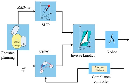
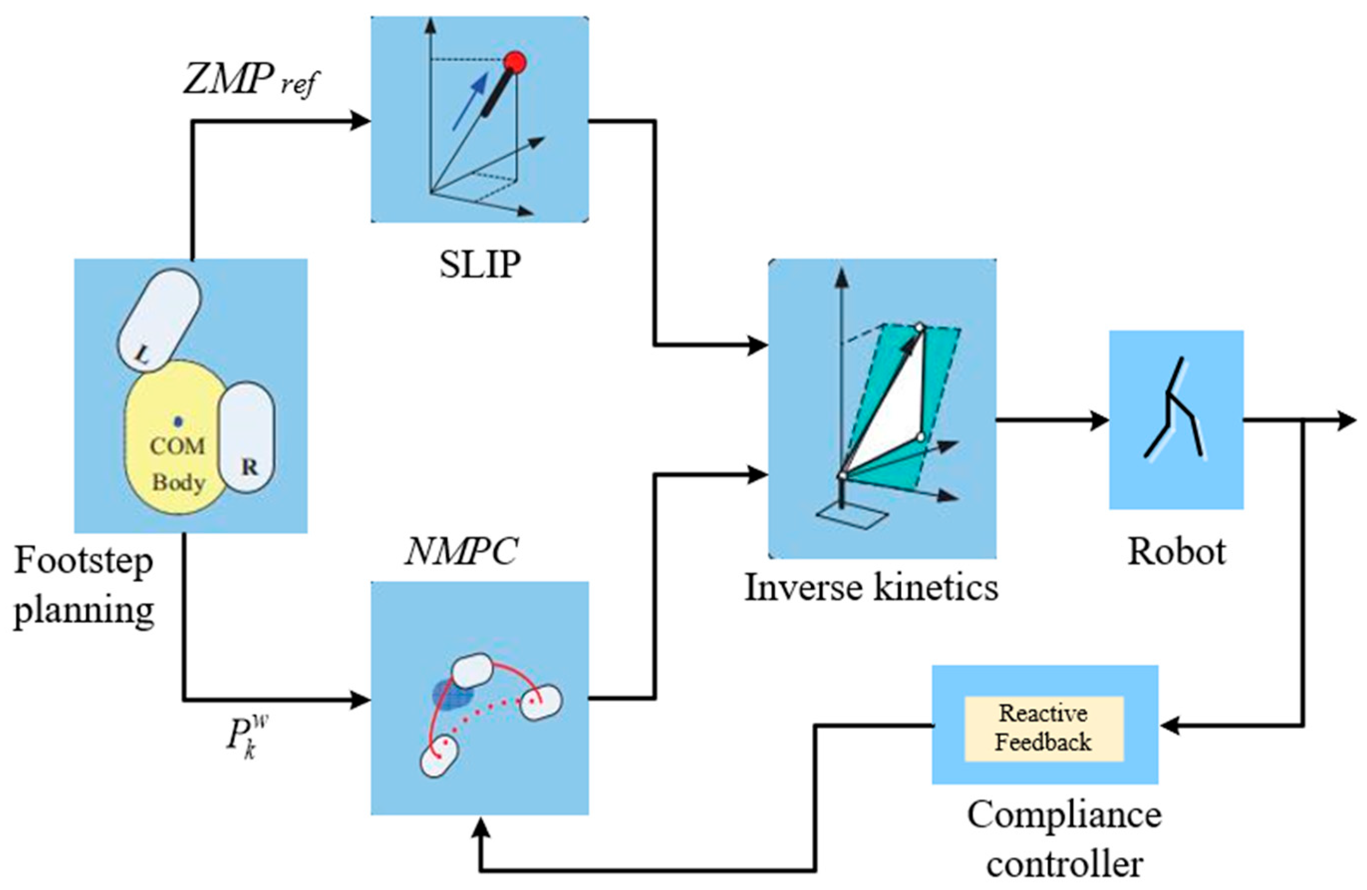
The core significance of compliance control is to enable robots to exhibit expected compliant behavior when interacting with environment. In this section, we present the compliance control framework in Figure 1. The proposed framework is fundamentally dependent on a sophisticated sensor suite which provides the necessary state feedback for stable and compliant bipedal locomotion. This integrated framework, as illustrated in Figure 1, relies on a sophisticated sensor suite that acts as the perceptual system, closing the loop between the high-level controller and the physical robot. The core control modules work in concert to achieve stable and compliant locomotion: an Impedance Control Strategy provides stabilization by modulating interaction forces; a nonlinear model predictive control (NMPC) framework performs real-time trajectory optimization; a modified reference generation module adjusts the swing foot’s position, velocity, and acceleration; and finally, stability criteria integrated with a pattern generator to regulate the robot’s center-of-mass (COM) dynamics to ensure overall balance. Figure 1 illustrates the control architecture for achieving compliant and stable biped walking. Details in the related work are as follows.
Figure 1.
The control schematic for compliant and stable biped walking.
- (1)
- Footstep planning: It determines feasible foot placements based on the robot’s COM and walking goals. The output of the footstep planner is a sequence of planned footstep positions, denoted as Pkw, which are then passed to the NMPC module for optimization.
- (2)
- SLIP model: It generates zero moment point (ZMP) reference trajectories using a spring-loaded inverted pendulum model.
- (3)
- Compliance controller: It modifies walking trajectories in real-time to adapt to external forces, ensuring compliant behavior. This controller generates a compensating COM acceleration adjustment to counteract disturbances in real time.
- (4)
- NMPC optimization: It refines footstep positions and walking parameters to maintain stability and trajectory feasibility. The NMPC module continuously solves a finite-horizon optimization problem. It uses the current and predicted state of the COM to refine the planned footsteps from the footstep planner and generate an optimal COM trajectory. It does this while respecting the robot’s dynamics and stability constraints, effectively closing the loop around future states.
- (5)
- Inverse Kinetics: It converts optimized trajectories into joint angles for execution.
- (6)
- Robot Execution: The robot performs walking motions based on the computed joint commands.
2.2. Modeling
Robot dynamic modeling serves as the fundamental mathematical representation of a robot’s physical behavior. It is the essential foundation for designing advanced model-based controllers such as impedance control, MPC, and computed-torque control. These controllers use the model to calculate the precise joint torques required to achieve a desired motion, compensate for the robot’s own inertia and coupling forces, and ensure stability.
Torso position compliance control (TPC) enables robots to respond to errors of external forces and foot forces, producing corresponding compliant effects. The basic idea lies in making the robot respond to errors and establishing a feedback control closed-loop, which is caused by external forces and ground reaction force. By calculating the reference value and actual value of ZMP, a compliant response can be made to external forces and foot forces.
Let C denote the position of the COM. A discrete-time state-space representation is employed to predict the COM trajectory over a finite horizon. The state vector at time step k is defined as , containing the COM position, velocity, and acceleration. The prediction model for future states is given by
where , , , k represents current time step index, j represents prediction step index within the horizon, and N is the prediction horizon length. m serves as the summation index, and i is the summation index, iterating over the intermediate steps whose control inputs contribute to the predicted state at step k + j; m ∈ {x, y} is the spatial component index, denoting the sagittal (x) and lateral (y) planes.
In order to make it convenient for the controller design, a three-dimensional inverted pendulum model is established to describe a humanoid robot. The zero moment point is the primary stability metric, which tells us that the ZMP reference must lie within the support polygon defined by the foot (or feet) in contact with the ground. Therefore, the planned ZMP is generated offline during the gait planning phase and then tracked online by the compliance controller. It is a direct function of the footstep positions, which themselves are determined by step length and step width, as well as the timing parameters including step duration and double support fraction. The controller continuously calculates the actual ZMP from the measured ground reaction forces. This is compared against the planned ZMP reference, and the resulting error signal is the direct input that drives the compliance controller to adjust the center-of-mass trajectory [24]. By establishing the positional relationship between the COM and ZMP,
where Z is short for ZMP. Zx and Zy are the zero moment point coordinates in the horizontal plane. h represents the constant height of the center of mass above the ground, assumed for the inverted pendulum model, g is the acceleration due to gravity, and n represents the prediction step index within the control horizon, n = 0, 1, …, N − 1.
The relationship between the calculated ZMP and the ZMP value that accounts for the system’s response delay is modeled as a first-order lag. The transfer function describes this dynamic in the continuous-time Laplace domain, where T is the time constant. A first-order lag is used to model the delayed response of the robotic system to measurement signals. This dynamic is incorporated into the state-space model. The relationship is defined by the following differential equation:
2.3. Torso Position Compliance Control
The torso position compliance control enhances the robot’s flexibility under external forces, thereby mitigating their impact. By adjusting the position of the center of mass, the robot is maintained in a balanced state. It plays the role of reducing the differences between the robot dynamics model and the real model. As derived in the paper, the magnitude and point of application of external disturbances can be estimated based on the discrepancy between the expected and measured ZMP, using the robot’s model. This estimation is critical for the resistance compliance controller to generate an appropriate counteracting virtual force. This is a standard approach for deriving a state-space model compatible with LQR design for a triple-integrator system representing position, velocity, and acceleration.
The expression for the robot state space is as follows:
A state feedback controller is designed to stabilize the system and minimize ZMP tracking error. The control input for this system is defined as the COM jerk . This is a standard approach for deriving a state-space model compatible with linear quadratic regulator (LQR) design for a triple-integrator system representing position, velocity, and acceleration [21,22]. A state feedback controller is utilized, and the control law is as follows,
where k1, k2, and k3 are feedback gain coefficients.
The control objective is to make the actual ZMP trajectory, denoted as p, accurately track its reference trajectory, pref. The cost functional J is designed to minimize both the ZMP tracking error and the control effort,
where Q and R are positive weighting coefficients.
The optimal feedback gain matrix is determined by solving the discrete-time infinite-horizon LQR problem. The optimal gain K is given by,
where P is the solution to the associated discrete-time algebraic Riccati equation,
where A and B are the state-space matrices derived from the discretized system dynamics, and Q and R are the weighting matrices from the cost function in Equation (7).
According to the control law (6), the acceleration of center of mass is generated by ZMP error and the position and velocity of center of mass, which plays a role in adapting to external forces and absorbing disturbances, achieving the effect of compliant control.
3. Resistance Torso Position Compliance Control
In order to maintain dynamic balance, a bipedal walking robot relies on complex control systems to simulate balance adjustments, including gait planning, joint torque control, and so on. Compared with wheeled robots, the algorithm and physical implementation for maintaining the stability of humanoid robots are more complex. In fact, advanced control algorithms and machine learning techniques are also needed, including path planning, gait generation, and so on. It will bring implementation difficulty and computational resource consumption of algorithms. Moreover, although bipedal walking can theoretically adapt to a wider range of terrains, it requires robots to judge the terrain accurately and make corresponding gait adjustments, such as walking up and down stairs and crossing obstacles. This increases the difficulty and computational complexity of navigation. In order to achieve precise fixed-point navigation, bipedal robots require highly accurate positioning systems and sensor fusion technology to ensure that each landing point conforms to the predetermined path, which requires high adaptability to irregular surfaces.
The TPC method in this section can only solve the disturbance resistance and compliance control problem of slow walking on flat ground with small disturbances. However, when the robot is subjected to continuous external force disturbances, for example, a slope on walking surface, robots may become unstable and tilt to one side. Hence, resistance compliance control is proposed to counteract the impact effect, which is based on the virtual force control and virtual model control. The main objective is to simulate the motion state of a robot under thrusting. The robot will firstly perform a compliant motion that conforms to the thrust, and then resist the thrust to perform a reverse motion.
3.1. Resistance Compliance Controller Design
The basic idea of resistance compliance control lies in establishing a virtual centroid model, which combines virtual force control and external force on the virtual model, and then generates torso adjustment through impedance control.
By establishing a three-dimensional inverted pendulum model of the robot, the magnitude of the external force acting on the center of mass can be estimated based on the value of ZMP.
where mo is the mass of the robot, is the position of center of mass, Fe is the external force acting on the center of mass, and and are the expected and true values of ZMP, respectively.
By solving (9), the expression for external force can be obtained,
where h is the constant height of the center of mass, which is an essential parameter of the linear inverted pendulum model used for simplified dynamics.
Impedance control aims to control the interaction between the robot and environment by adjusting robot impedance, including inertia, damping, and stiffness. The core idea is to add virtual impedance to the robot end effector of the robot, so that the robot can exhibit the expected response characteristics when subjected to external forces.
where Kp is the spring stiffness coefficient, Kd is damping coefficient, and Km is the mass of model. Assume that the mass of model is consistent with the actual mass of the robot, so Km = mo.
Substitute (10) into (11), and obtain the state equation of the robot described by external force as follows:
The virtual force controller can be divided into two parts, including a virtual resistance controller and a model predictive controller. The former is used to resist the effects of natural movement, and the latter ensures that the actual ZMP value can track the reference ZMP value during the robot’s walking process. When using virtual force control to calculate ZMP value, future ZMP value should be considered in advance to overcome the impact of response lag. Based on the design concept of the controller mentioned above, the following is the specific design process of the resistant virtual force controller. It takes the external forces as the input and the output resistance virtual interior as the control variable, whose expression can be described as
where is the negative coefficient, and the value of K2 should ensure that the original robot system has critical damping. Increasing Kp improves disturbance rejection at the cost of higher required joint torques and potential instability if it is too high. The damping ratio Kd is critical for suppressing oscillations; a value yielding provides the best balance between speed and smoothness. The resistance gain K1 must be negative and sufficiently large (within [−1.4, −1.1] [−1.4, −1.1]) to effectively counteract the push, but values beyond this range can induce aggressive, energy-inefficient motions.
Due to the resistance effect occurring after compliance control, the resistance lags behind the external force. A first-order lag is utilized to simulate the delayed application of the resistance virtual force. The dynamic relationship between the commanded resistance force and the applied virtual force is given by the following differential equation.
For implementation in the discrete-time controller, this is converted to a difference equation. Using a backward Euler discretization with time step Δt, the implemented equation is as follows:
3.2. Nonlinear Model Predictive Control Based on Parameter Optimization
ZMP control provides a clear, intuitive, and computable stability metric for legged robots. By ensuring the ZMP remains within the support polygon, the controller can directly guarantee the robot’s balance against tipping over. The ZMP criterion leads to relatively straightforward control laws and gait generation algorithms. This computational efficiency makes it suitable for real-time balance control on robots with limited processing power. MPC’s core advantage is its ability to predict the robot’s future states over a horizon. This allows it to take proactive, anticipatory actions to maintain stability, rather than just reacting to current errors. It can, for instance, initiate a recovery motion before a push causes a significant balance loss. It can systematically and explicitly incorporate physical limitations and safety constraints directly into the control calculation. This prevents the controller from generating commands that are infeasible or unsafe for the robot to execute.
Consider a frame P attached to the support foot, with its current position and orientation on the ground given by , with . The future steps are denoted by,
where represents the foot support position at each time step, and indicates which step falls in the sampling interval.
The NMPC optimization problem is formulated as a constrained minimization over the control sequence Uk. The objective is to find the sequence Uk that minimizes the following composite cost function,
where J(Uk) is the total cost to be minimized. J1(Uk), J2(Uk), and J3(Uk) are the specific cost terms for linear velocity tracking, angular velocity tracking, and foot placement. λ and μ are the weighting coefficients that balance the relative importance of these objectives.
represents the cost function related to the linear velocity tracking,
is the cost function minimizing the distance between the CoP and the projection of the ankle on the sole,
4. Experimental Verification and Results
4.1. Construction of Experimental Environment
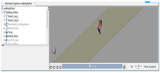
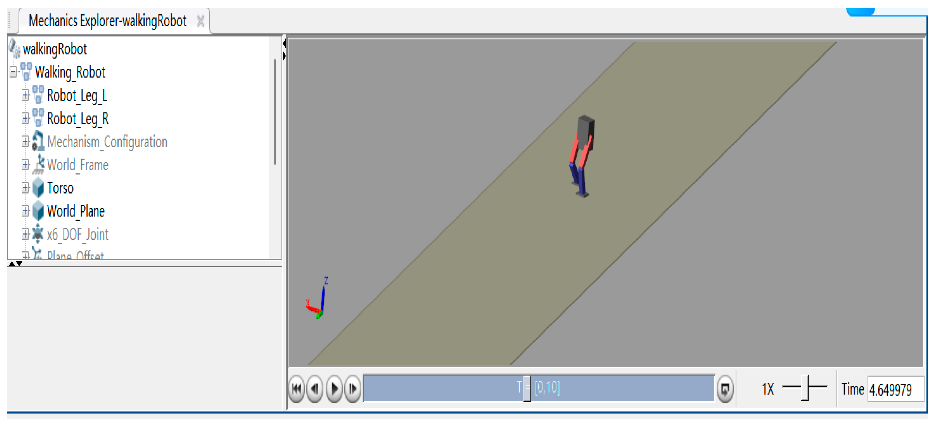
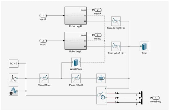
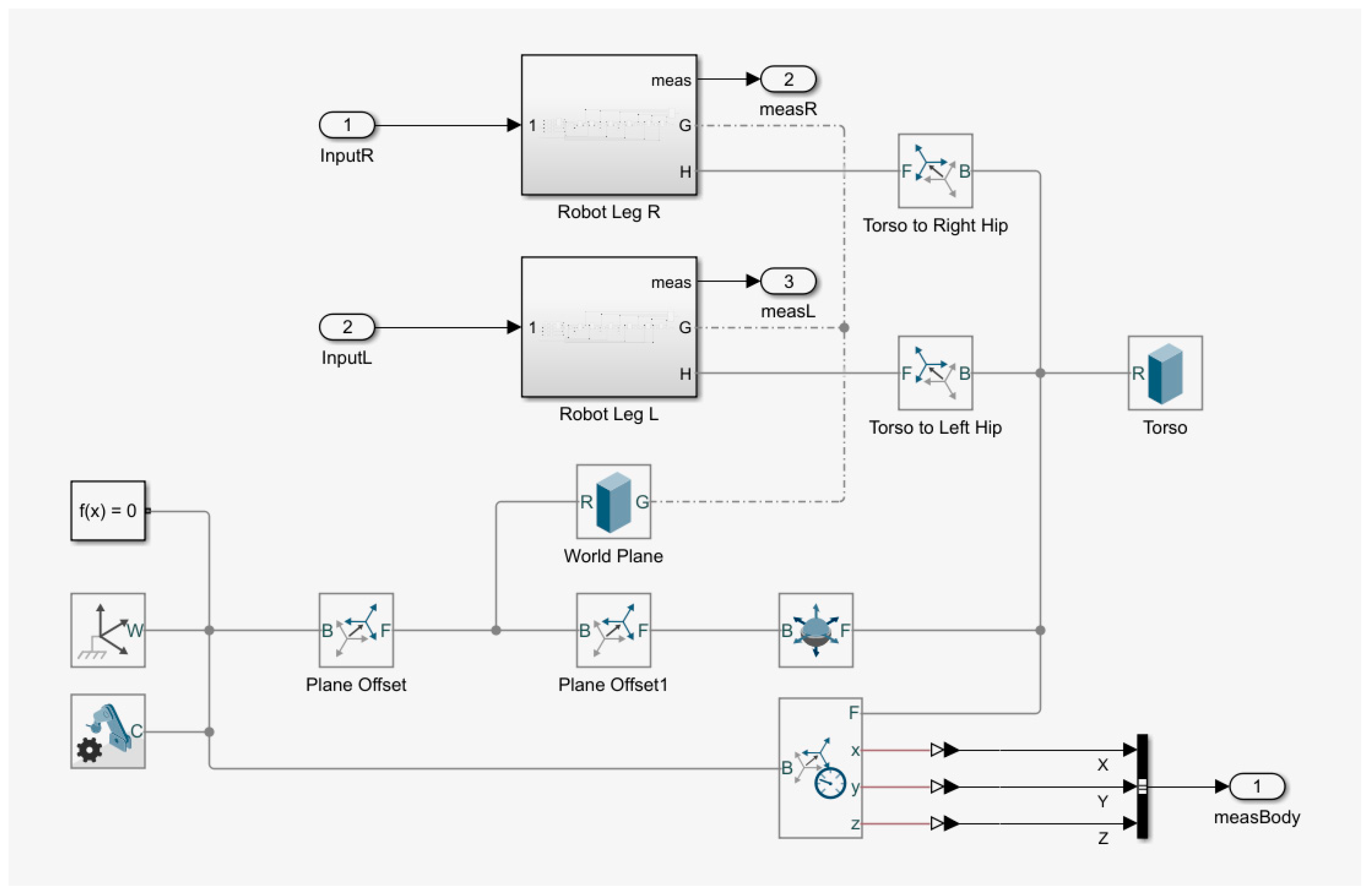
To verify control and optimization methods given in Section 2 and Section 3, a hierarchical whole-body control architecture was designed. The lower layer employs a task-priority-based quadratic programming solver to decompose high-level motion commands into joint-space control variables, while integrating sensor data to construct a closed-loop feedback system. The modeling diagram is shown in Figure 2, which is used to complete the kinematic analysis and gait planning simulation.
Figure 2.
The robot simulation modeling diagram.
In practical environments, due to factors such as mechanical structural errors, inherent model deviations, and ground friction, there is a certain deviation between the actual gait and the expected gait. If errors continue to accumulate, it will cause the robot to become imbalanced and capsize. In order to ensure smooth walking, real-time calibration is required. The details in gait planning and control module of the robot are shown in Figure 3, which is implemented and simulated in an MATLAB2022b/Simulink environment.
Figure 3.
The gait planning and control module of the robot.
The robot configuration parameters are shown in Table 1. The compliance controller generates control variables for the centroid acceleration based on the ZMP error, as well as the current centroid position, velocity, and adjustment position. The characteristics of admittance control enable robots to exhibit a motion mode that conforms to external forces and absorbs disturbances, achieving the effect of compliant control. The weight matrix in Equations (7) and (8) is Q = diag [1, 1, 1], R = 0.0001. The cost function gains in Equation (16) are λ = 2.5, μ = 100.
Table 1.
Robot parameters.
4.2. Result Analysis
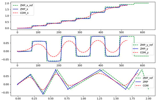
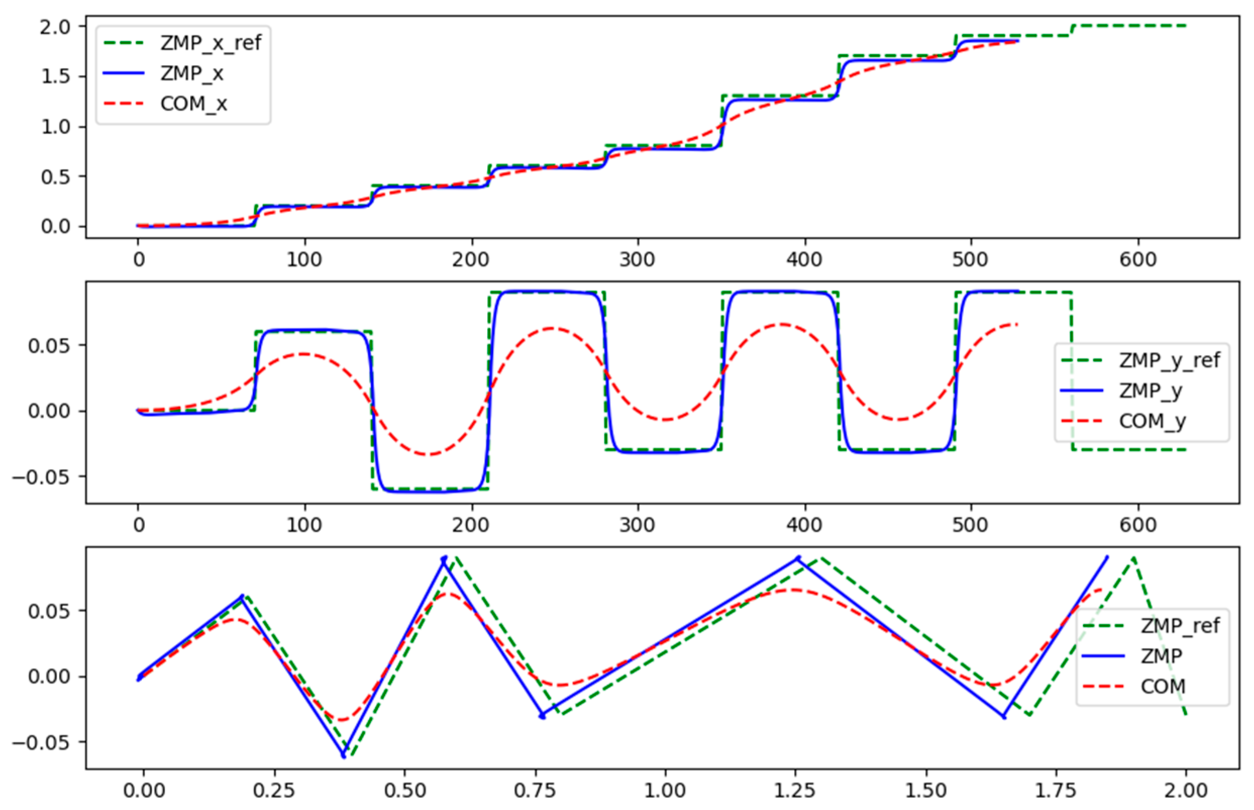
A comparative analysis was conducted to evaluate the performance of the proposed control framework against a baseline system. The simulation results of TPC and NMPC optimization are shown as follows. In order to see the performance changes better, the robot system without TPC and NMPC optimization is also utilized for comparative simulation. The preview control algorithm generates the motion trajectories for the centroid and the ZMP based on a sequence of predefined footstep landing points. These trajectories are plotted for analysis and visualization, as shown in Figure 4. Without considering ZMP error feedback, the ZMP preview control algorithm gradually accumulates errors as the forward distance increases, resulting in differences between the actual ZMP trajectory and the planned ZMP reference point, as shown in Figure 4. The planned and actual trajectories of the COM and the ZMP in the horizontal plane are observed. The plot illustrates the robot’s motion over time, with the COM trajectory (solid line) and the ZMP trajectory (dashed line) shown in world coordinates. The results compare the system’s performance with and without the proposed TPC.
Figure 4.
The motion trajectory of the COM and ZMP.
Table 2 compares the proposed method with not only the traditional ZMP preview control but also two contemporary approaches: a modern MPC-based push recovery controller and a hybrid impedance–MPC method. The results show that while modern MPC and hybrid methods already improve upon the traditional baseline, our integrated framework achieves the lowest ZMP tracking errors and the fastest settling time, demonstrating superior disturbance rejection performance. It is noted that our method incurs a slightly higher computational cost due to the coupled optimization of compliance and footstep planning, which remains within real-time feasibility.
Table 2.
Comparisons of the proposed method with contemporary approaches.
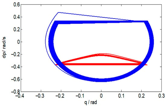
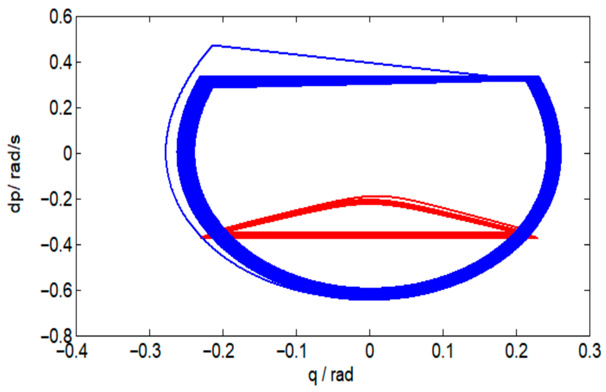
In Figure 5, the phase portraits of the joint angles and angular velocities exhibit convergence to a stable, periodic orbit. This pattern indicates that the closed-loop system achieves periodic and stable walking, which is a fundamental requirement for robust bipedal locomotion. While the system is under active control, the resulting periodic trajectory represents a limit cycle of the controlled dynamics. The above simulation results show that the impedance control can achieve good force tracking effect when the robot operates on a plane or the environment stiffness varies. The stability of the generated walking gait is validated through phase diagrams.
Figure 5.
Phase diagram of walking trajectory.
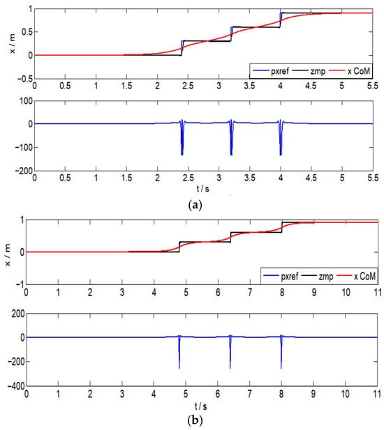
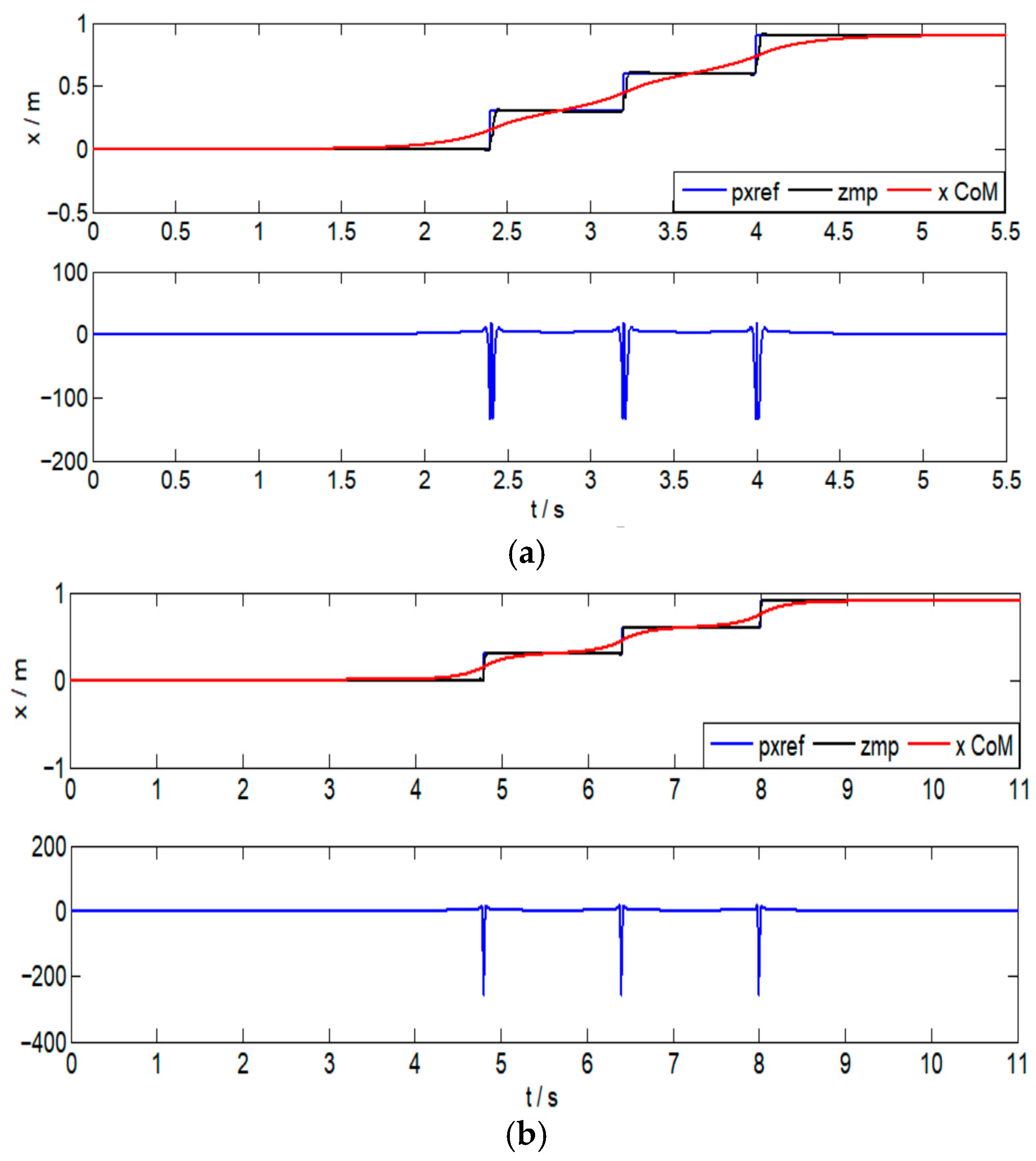
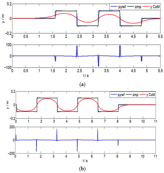
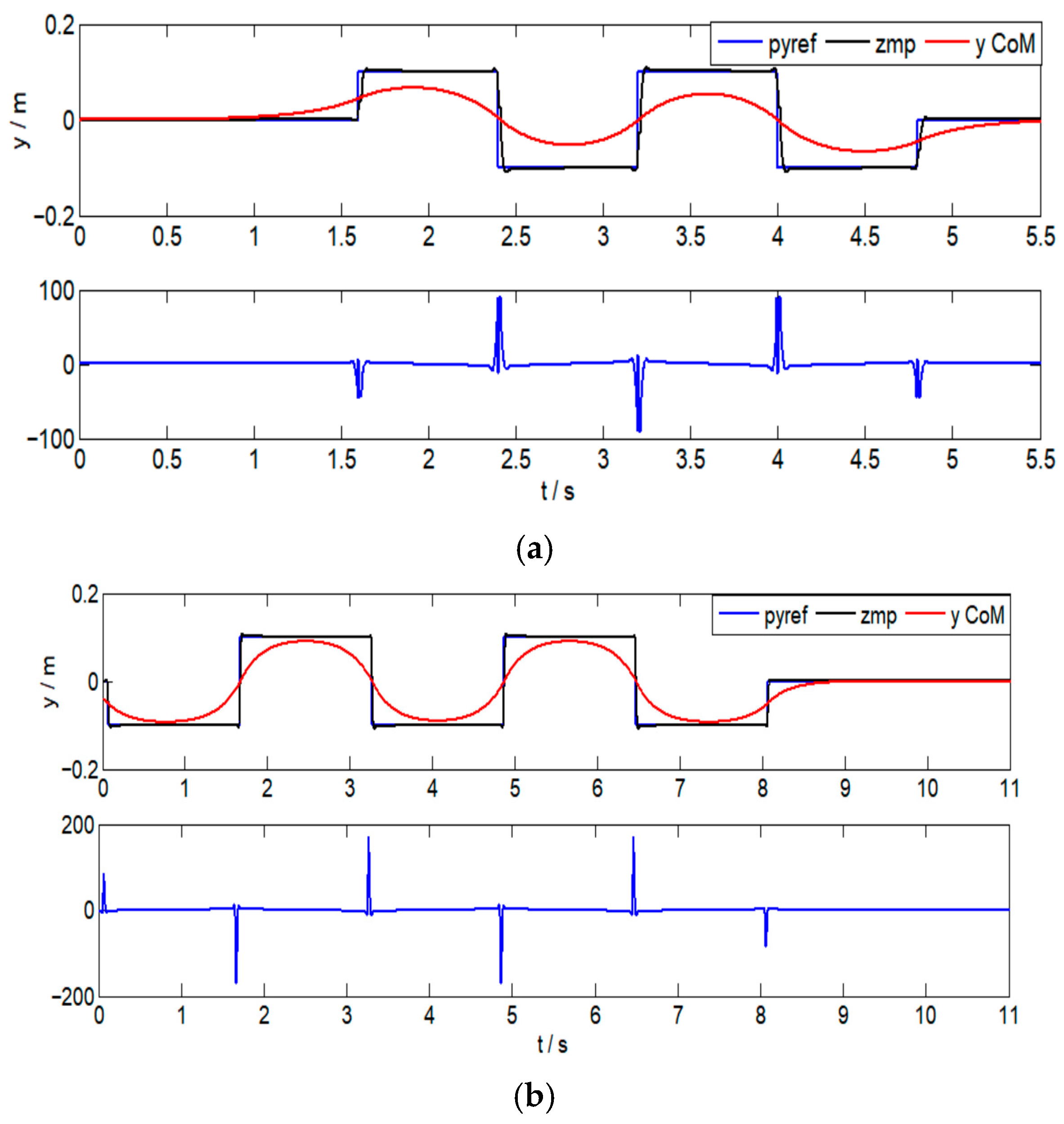
Figure 6 and Figure 7 show the trajectory tracking effect in the X and Y directions, respectively. Figure 6 compares the ZMP and COM trajectory tracking in the sagittal (X) plane Figure 6a without and Figure 6b with the TPC. The key observation is not merely the closer tracking in Figure 6b, but the nature of the error correction. In Figure 6a, the ZMP error exhibits a low-frequency, accumulating drift, indicative of the baseline controller’s inability to reject the sustained component of the disturbance. In contrast, in Figure 6b, the error shows higher-frequency, bounded oscillations that converge toward zero. This pattern demonstrates that the TPC is actively generating a counteracting virtual force, via Equation (13), leading to a dynamic equilibrium rather than a passive drift. The larger initial error peak in Figure 6b reflects the controller’s deliberate, compliant absorption of the impact before initiating the resistant phase, a trade-off that ultimately yields zero steady-state error. The tracking error of ZMP will converge to zero after a certain number of walking steps in Figure 7, which shows the effect of adaptive impedance control on the complex surface for force tracking. The proposed framework, which integrates torso position compliance (TPC) control and NMPC optimization, demonstrates superior zero moment point (ZMP) tracking accuracy. It is visually evident that the actual ZMP trajectory closely follows its reference when TPC and NMPC are active. In contrast, the system without TPC exhibits significant and sustained deviation from the reference trajectory.
Figure 6.
The trajectory tracking effect in the X direction. (a) Without TPC; (b) with TPC.
Figure 7.
The trajectory tracking effect in the Y direction. (a) Without TPC; (b) with TPC.
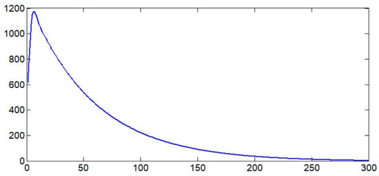
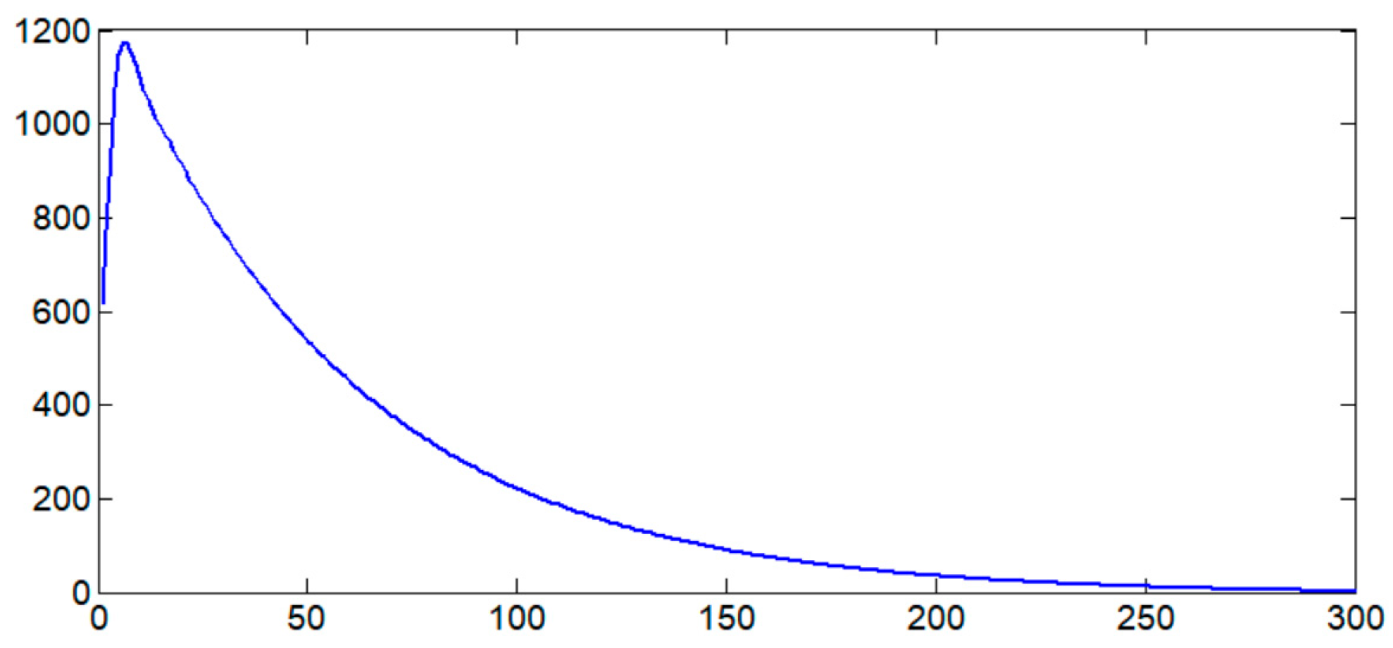
A critical quantitative result is the convergence of the ZMP tracking error. Figure 8 plots the Euclidean norm of the ZMP tracking error over time, critically comparing the proposed integrated framework against the baseline. The proposed controller not only achieves faster convergence, but also exhibits a distinct two-phase convergence profile—an initial rapid reduction followed by a slower, asymptotic approach to zero. This underscores the synergistic time-scale separation in our architecture: a fast reaction stabilizes the immediate state, while predictive optimization ensures long-term stability. The baseline’s monotonically increasing error highlights its lack of a mechanism to counteract sustained disturbances. This confirms the controller’s ability to eliminate steady-state error and maintain dynamic balance over time, a feature not achieved by the baseline controller where errors accumulate.
Figure 8.
The variation in trajectory tracking error over time.
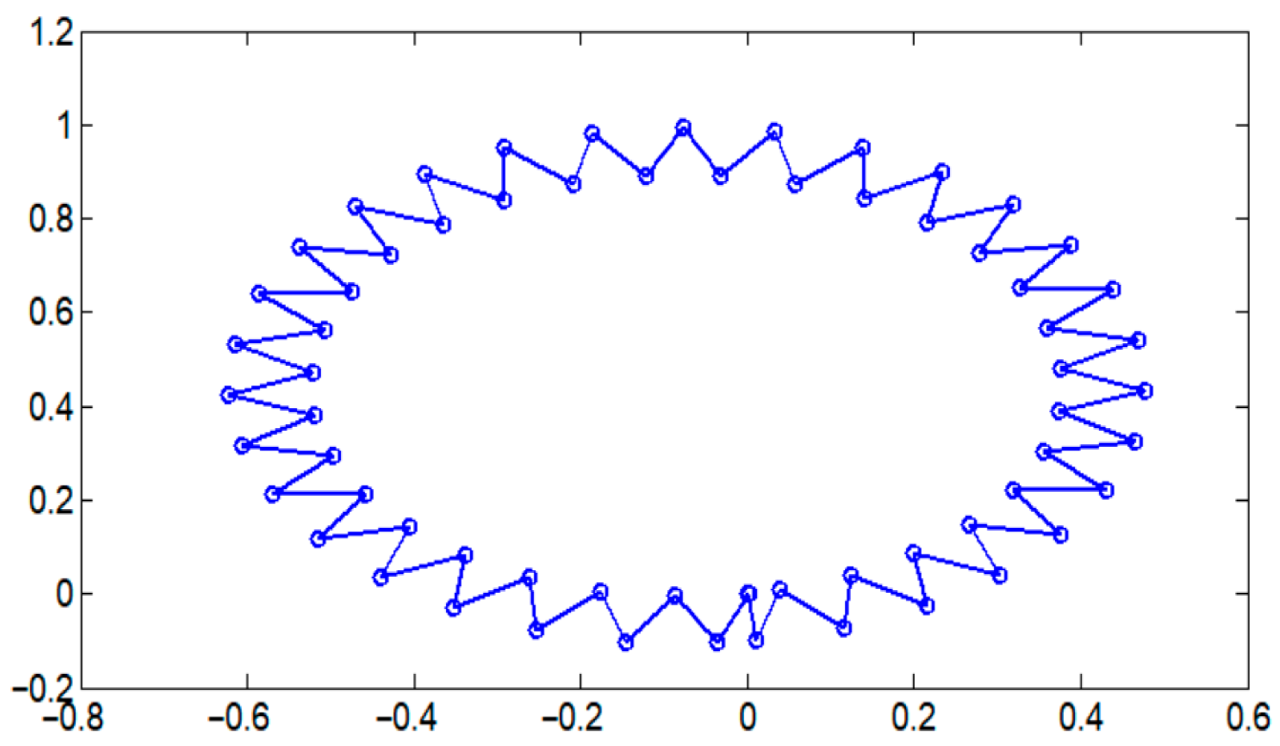
Figure 9 demonstrates the predictive capability of the NMPC module within the integrated framework. The COM trajectory smoothly follows a curved path while maintaining stability. More importantly, the footstep placements are continuously adapted ahead of the COM motion. This demonstrates the controller’s capability to handle non-straightline paths while maintaining stability. This pre-emptive adjustment is the key advantage over reactive-only controllers: the NMPC does not just follow the path but optimizes the future contact sequence to maintain the ZMP within the support polygon before the COM dynamics push it to the boundary. This explains the smoothness of the COM trajectory despite the changing direction, which is a direct result of the optimization in Equation (16) minimizing future tracking error and instability. The overall performance of the proposed compliant control was verified through the motion trajectory of the humanoid robot. The effectiveness of the NMPC-based walking pattern generator is further illustrated by the center-of-mass trajectory.
Figure 9.
The center-of-mass trajectory with NMPC optimization.
The collective results from the simulations confirm that the integrated framework is robust to environmental variations and external perturbations. The impedance control mechanism allows the robot to adapt its interaction with the environment, leading to improved force tracking and disturbance rejection. The text notes that the proposed method improves disturbance rejection capability by over 30% compared to traditional ZMP tracking methods. The traditional ZMP tracking method referred to in our study is the ZMP preview control algorithm, a classic and widely adopted approach for bipedal gait generation, as pioneered by Kajita et al. [24]. Table 3 shows the quantitative performance comparison between the traditional ZMP preview control and the proposed method under external disturbance. In conclusion, the comparative analysis in Section 4 provides strong evidence that the synergistic combination of the resistance torso compliance controller and the NMPC-based footstep planner significantly enhances tracking precision, stability, and overall robustness in bipedal walking compared to a system lacking these advanced components.
Table 3.
Quantitative performance comparison.
5. Conclusions
In conclusion, this paper has presented an integrated control framework whose novelty stems from the tight coupling of a reactive resistance compliance mechanism with a predictive NMPC planner. The proposed ‘resistance’ torso controller provides a new capability to counteract sustained disturbances, while the reformulated NMPC optimizes footsteps in a way that is inherently conscious of the compliant system’s dynamics. The core of this strategy lies in the synergistic combination of a torso position compliance controller and an NMPC-based walking pattern generator.
The compliance controller, optimized via an LQR formulation, enables the robot to exhibit immediate and compliant responses to external disturbances by adjusting its center-of-mass trajectory. Furthermore, the proposed resistance compliance mechanism extends this capability, allowing the robot to counteract sustained external forces. The NMPC module complements this by providing predictive footstep planning, simultaneously optimizing foot position and orientation in real-time while adhering to ZMP stability criteria and centroidal momentum dynamics. This integration ensures that the robot can not only react to disturbances but also proactively plan for stability. It is important to note that the current framework demonstrates robust disturbance rejection and tracking for a given walking path. However, it does not incorporate a high-level reactive re-planning module to handle the sudden appearance of unforeseen obstacles. The integration of real-time perception, such as depth vision, with the NMPC-based gait generator to enable fully autonomous navigation in dynamic environments represents a critical and exciting direction for our future work.
Simulation results have validated the effectiveness of the proposed method. The framework demonstrated accurate ZMP trajectory tracking with errors converging to zero, the establishment of stable limit cycles indicative of periodic walking, and the ability to execute complex motion trajectories. These outcomes confirm that the controller is robust to environmental variations and external perturbations. It should be noted that the current experimental simulations primarily focused on forward-directed thrusts and moderate slopes. While these scenarios demonstrate the controller’s core capability to reject sustained disturbances, real-world deployments may involve multi-directional forces, varying intensities, and more complex terrains such as uneven surfaces, stairs, or dynamic obstacles. Future work will expand the validation to include these broader conditions. In addition, the primary limitation of this work is the lack of physical hardware validation. Future work will focus on porting the framework to a humanoid platform, addressing the aforementioned challenges of state estimation, actuator constraints, and real-time optimization. Initial implementation will prioritize robustness to model uncertainty and sensor noise.
Funding
This work is supported by National Natural Science Foundation of China (grant number 62503334, 62573322) and the Artificial Intelligence Promotes Research Paradigm Reform and Empowers Discipline Leap Plan Project AIZX-12.
Data Availability Statement
The original contributions presented in this study are included in the article. Further inquiries can be directed to the corresponding author.
Conflicts of Interest
The author declares no conflicts of interest.
References
- Radosavovic, I.; Zhang, B.; Shi, B.; Rajasegaran, J.; Kamat, S.; Darrell, T.; Sreenath, K.; Malik, J. Humanoid locomotion as next token Prediction. arXiv 2024, arXiv:2402.19469. [Google Scholar] [CrossRef] [Scilit]
- Devi, M.A.; Udupa, G.; Sreedharan, P. A novel under-actuated multi-fingered soft robotic hand for prosthetic application. Robot. Auton. Syst. 2017, 100, 267–277. [Google Scholar]
- Radosavovic, I.; Xiao, T.; Zhang, B.; Darrell, T.; Malik, J.; Sreenath, K. Real-world humanoid locomotion with reinforcement Learning. Sci. Robot. 2024, 9, eadi9579. [Google Scholar] [CrossRef] [Scilit] [PubMed]
- Liu, Y.; Wensing, P.; Schmiedeler, J. Terrain-Blind Humanoid Walking Based on a 3D Actuated Dual-SLIP Model. IEEE Robot. Autom. Lett. 2016, 1, 1073–1080. [Google Scholar] [CrossRef] [Scilit]
- Ji, Y.; Li, Z.; Sun, Y.; Peng, X.B.; Levine, S.; Berseth, G.; Sreenath, K. Hierarchical reinforcement learning for precise soccer shooting skills using a quadrupedal robot. In Proceedings of the 2022 IEEE/RSJ International Conference on Intelligent Robots and Systems (IROS), Kyoto, Japan, 23–27 October 2022; pp. 1479–1486. [Google Scholar]
- Luo, S.; Jiang, M.; Zhang, S.; Luo, S.; Jiang, M.; Zhang, S.; Zhu, J.; Yu, S.; Silva, I.D.; Wang, T.; et al. Experiment-free exoskeleton assistance via learning in simulation. Nature 2024, 630, 353–359. [Google Scholar] [CrossRef] [Scilit] [PubMed]
- Dong, W.; Cheng, X.; Xiong, T.; Wang, X. Stretchable bio-potential electrode with self-similar serpentine structure for continuous, long-term, stable ECG recordings. Biomed. Microdevices 2019, 21, 6. [Google Scholar] [CrossRef] [Scilit] [PubMed]
- Lee, J.; Hwangbo, J.; Wellhausen, L.; Koltun, V.; Hutter, M. Learning quadrupedal locomotion over challenging terrain. Sci. Robot. 2020, 5, 5986. [Google Scholar] [CrossRef] [Scilit] [PubMed]
- Yadukumar, S.; Ames, A.D. Human-inspired under-actuated bipedal robotic walking with AMBER on flat ground, up-slope and uneven terrain. In Proceedings of the 2012 IEEE/RSJ International Conference on Intelligent Robots and Systems (IROS 2012), Vilamoura, Portugal, 7–12 October 2012; pp. 2478–2483. [Google Scholar]
- Duan, H.; Pandit, B.; Gadde, M.S.; van Marum, B.J.; Dao, J.; Kim, C.; Fern, A. Learning vision-based bipedal locomotion for challenging terrain. arXiv 2023, arXiv:2309.14594. [Google Scholar] [CrossRef] [Scilit]
- Feng, G.; Zhang, H.; Li, Z.; Peng, X.B.; Basireddy, B.; Yue, L.; Song, Z.; Yang, L.; Liu, Y.; Sreenath, K. Genloco: Generalized locomotion controllers for quadrupedal robots. In Proceedings of the 6th Conference on Robot Learning, PMLR, Atlanta, GA, USA, 6–9 November 2023; pp. 1893–1903. [Google Scholar]
- Schreff, L.; Haeufle, D.F.B.; Vielemeyer, J.; Müller, R. Evaluating anticipatory control strategies for their capability to cope with step-down perturbations in computer simulations of human walking. Sci. Rep. 2022, 12, 10075. [Google Scholar] [CrossRef] [Scilit] [PubMed]
- Savin, S. ZMP-based trajectory generation for bipedal robots using quadratic programming. In Control and Signal Processing Applications for Mobile and Aerial Robotic Systems; IGI Global Scientific Publishing: Hershey, PA, USA, 2020. [Google Scholar]
- Or, Y.; Ames, A.D. Stability and completion of zeno equilibria in lagrangian hybrid systems. IEEE Trans. Autom. Control 2011, 56, 1322–1336. [Google Scholar] [CrossRef] [Scilit]
- He, T.; Luo, Z.; Xiao, W.; Zhang, C.; Kitani, K.; Liu, C.; Shi, G. Learning human-to-humanoid real-time whole-body teleoperation. arXiv 2024, arXiv:2403.04436. [Google Scholar]
- Sun, S.; Huang, Y.; Wang, Q. Adding adaptable toe stiffness affects energetic efficiency and dynamic behaviors of bipedal walking. J. Theor. Biol. 2016, 388, 108–118. [Google Scholar] [CrossRef] [Scilit] [PubMed]
- Su, H.; Qi, W.; Hu, Y.; Karimi, H.R.; Ferrigno, G. An incremental learning framework for human-like redundancy optimization of anthropomorphic manipulators. IEEE Trans. Ind. Inform. 2020, 18, 1864–1872. [Google Scholar] [CrossRef] [Scilit]
- Jenelten, F.; He, J.; Farshidian, F.; Hutter, M. DTC: Deep tracking control. Sci. Robot. 2024, 9, 5401. [Google Scholar] [CrossRef] [Scilit] [PubMed]
- Krishna, L.; Mishra, U.A.; Castillo, G.A.; Hereid, A.; Kolathaya, S. Learning Linear Policies for Robust Bipedal Locomotion on Terrains with Varying Slopes. In Proceedings of the 2021 IEEE/RSJ International Conference on Intelligent Robots and Systems (IROS), Prague, Czech Republic, 27 September–1 October 2021; pp. 5159–5164. [Google Scholar]
- Carpentier, J.; Mansard, N. An efficient contact dynamics algorithm for humanoid robots using over-approximation and iterative scaling. In Proceedings of the IEEE International Conference on Robotics and Automation (ICRA), Brisbane, Australia, 21–25 May 2018; pp. 3651–3657. [Google Scholar]
- Klein, J.; Schüller, D.; Behnke, S. An MPC framework for humanoid push recovery. In Proceedings of the IEEE/RSJ International Conference on Intelligent Robots and Systems (IROS), Prague, Czech Republic, 27 September–1 October 2021; pp. 5159–5164. [Google Scholar]
- Feng, G.; Zhang, H.; Li, Z.; Peng, X.B.; Basireddy, B. Hybrid impedance-MPC for bipedal locomotion on uneven terrain. IEEE Robot. Autom. Lett. 2023, 8, 2182–2189. [Google Scholar]
- Sleiman, J.P.; Farshidian, F.; Minniti, M.V.; Hutter, M. A unified MPC framework for whole-body dynamic locomotion and manipulation. In Proceedings of the IEEE International Conference on Robotics and Automation (ICRA), Philadelphia, PA, USA, 23–27 May 2022; pp. 4688–4694. [Google Scholar]
- Kajita, S.; Kanehiro, F.; Kaneko, K.; Fujiwara, K.; Harada, K.; Yokoi, K.; Hirukawa, H. Biped walking pattern generation by using preview control of zero-moment point. In Proceedings of the IEEE International Conference on Robotics and Automation (ICRA), Taipei, Taiwan, 14–19 September 2003. [Google Scholar]

Disclaimer/Publisher’s Note: The statements, opinions and data contained in all publications are solely those of the individual author(s) and contributor(s) and not of MDPI and/or the editor(s). MDPI and/or the editor(s) disclaim responsibility for any injury to people or property resulting from any ideas, methods, instructions or products referred to in the content. |
© 2026 by the author. Licensee MDPI, Basel, Switzerland. This article is an open access article distributed under the terms and conditions of the Creative Commons Attribution (CC BY) license.