


Abstract
The transient magnetic field (TMF) generated by disconnector and circuit-breaker operations in substations represents a major class of electromagnetic disturbances that can compromise the reliable operation of magnetic sensors. However, laboratory methods capable of reproducing the waveform characteristics of such TMF remain limited, which restricts systematic immunity testing and quantitative evaluation of magnetic sensors. To bridge this gap, this study summarizes measured and simulated data on switching-operation transient voltages, transient currents, and TMF reported in the literature and extracts characteristic parameters related to time-domain waveform, frequency distribution, and field-strength range. Guided by these parameters, a TMF waveform reproduction method based on characteristic-parameter equivalence is proposed, and a magnetic-field immunity simulation device is developed. The device combines a rectangular coil with a cross-nested multidirectional rotating mechanism and integrates FPGA-based programmable waveform generation, high-frequency power amplification, and broadband impedance matching. This configuration enables directionally controllable 360° output of bipolar damped oscillatory magnetic fields. The test results show that the device can generate programmable bipolar damped oscillatory magnetic fields over a frequency range of 0.1–30 MHz, with an adjustable peak-to-peak magnetic-field strength reaching 800 A/m. The oscillation frequency and pulse-train parameters are programmable, while the generated magnetic field reproduces the representative damped-oscillatory characteristics of switching-operation TMF. This study provides a theoretical basis and an experimental platform for immunity testing and protective-design verification of magnetic sensors in complex high-frequency magnetic-field environments.
1. Introduction
With the rapid advancement of new power system construction, online condition monitoring of power transmission and transformation equipment has become increasingly important. Magnetic sensors based on tunneling magnetoresistance (TMR) and giant magnetoresistance (GMR) have been widely adopted for current measurement and primary equipment state monitoring, owing to their high sensitivity, miniaturization and non-contact measurement characteristics [1,2,3]. Generally installed in the vicinity of current-carrying conductors, these sensors are inevitably exposed to complex electromagnetic environments inside substations, posing severe challenges to their operational stability and measurement accuracy [4,5].
Switching operations of disconnectors and circuit breakers are dominant sources of transient electromagnetic disturbances in substations [6]. Although existing standards such as IEC 61000-4-9 and IEC 61000-4-10 specify immunity test methods for the damped oscillatory magnetic field and the pulse magnetic, their applicability is limited to traditional sensing devices, such as electronic equipment installed on the secondary side. As mentioned earlier, magnetic sensors have been widely used in substations and power grid systems in recent years and are generally installed directly and in close proximity to the primary side, where the operating environment is more complex and the disturbances encountered are more severe. Consequently, the existing standards are insufficient to meet the development requirements of magnetic sensors, especially with respect to transient magnetic field disturbances caused by substation switching operations [7].
To characterize the time–frequency features of switching-operation disturbances, extensive field measurements and simulation studies have been conducted. Li et al. performed field measurements and statistical analysis of transient electric fields in a 110 kV GIS substation and found that the main energy was concentrated near 3 MHz, 10 MHz, and 30 MHz. They also established a laboratory platform for simulating transient electric-field radiation and quantitatively analyzed the coupling characteristics with sensor cables [8]. Wu et al. and Wang et al. measured conducted interference voltages generated by switching operations on three full-scale 500 kV and 220 kV test platforms and established quantitative relationship models for port disturbances [9,10]. Luo et al. systematically compared the electromagnetic disturbance characteristics of AIS and GIS at a 330 kV full-scale test site and showed that the dominant disturbance frequency generated by GIS can reach 17–20 MHz, with higher amplitudes and more intense oscillations [11]. These studies provide an important basis for understanding the transient electromagnetic environment in substations and for designing immunity measures for secondary equipment. However, most of the above work has focused on transient electric fields, conducted interference voltages, and the immunity design of conventional secondary electronic equipment. Research on the influence mechanism of transient magnetic fields (TMF) generated by switching operations on magnetic sensors, as well as on dedicated immunity test methods, remains insufficient.
Magnetic sensors take the spatial magnetic field as their direct measurand and are therefore more sensitive to spatial magnetic field disturbances than conventional electronic equipment. During switching-on and switching-off operations, repeated arc reignition and extinction between the contacts excite very fast transient overvoltages and steep-front transient currents. Such broadband, high-amplitude currents radiate into space, producing high-amplitude, wideband transient magnetic fields. Because magnetic sensors are located directly in the near-field region of the primary side, the amplitude of the transient magnetic field they experience is far higher than that at secondary equipment installed in control rooms or cable trenches. To determine the actual magnitude and characteristics of transient magnetic fields, specialized field measurements have been carried out. Huang et al. developed a broadband point-measurement system based on magnetoresistive sensors and measured TMF generated by switching operations at a distance of 3 m from a bushing in a 110 kV substation. The measured dominant frequency reached 3.66 MHz, the peak value was approximately 495 A/m, and the TMF induced an interference voltage of 1.4 to 1.7 V per unit area in secondary circuits [12]. Liu et al. further conducted field measurements in a ±800 kV ultrahigh-voltage converter station and showed that the peak TMF generated by disconnector operation near the current-transformer terminal box approached 800 A/m [13]. These field measurements confirm that switching-operation TMF can pose a substantial threat to nearby secondary equipment. Because these magnetic fields have concentrated energy, they can intrude into sensitive elements and signal-conditioning circuits of magnetic sensors through radiative coupling, leading to increased measurement errors, data packet loss, or even irreversible device damage. Accurate reproduction of such TMF disturbances is therefore a prerequisite for evaluating and improving sensor immunity under laboratory conditions.
Existing interference-resistant designs for magnetic sensors have mainly focused on shielding structures and magnetic-circuit optimization. Wang et al. proposed an anti-interference scheme for GMR current sensors based on electromagnetic shielding and PCB electromagnetic-compatibility design [14]. Hu et al. designed a multistage magnetic-ring structure that improves the sensitivity of weak-current measurement while enhancing resistance to magnetic interference [15]. Khawaja et al. designed a multilayer high-permeability alloy shielding structure to attenuate external magnetic-field noise [16]. However, current verification studies of the anti-interference performance of magnetic sensors have primarily used static disturbance sources [17]. The influence of switching-operation TMF on the performance of magnetic sensors has not been systematically investigated. In general, current research on magnetic sensors remains focused on passive protection design (optimizing shielding enclosures, magnetic circuit structures, and filtering circuits), while a laboratory simulation method that can accurately reproduce the TMF waveform characteristics generated by substation switching operations is still lacking, and this limitation prevents systematic immunity grading tests and quantitative evaluation of different protection designs under controlled conditions.
To bridge this gap, this paper focuses on transient high-frequency magnetic fields generated by disconnector operations in substations. Field measurement and simulation data reported in the literature are systematically analyzed to extract the key waveform parameters of switching-operation TMF. A TMF waveform reproduction method based on characteristic-parameter equivalence is then proposed. On this basis, a magnetic-field disturbance simulation test platform dedicated to magnetic sensors is constructed, enabling 360° omnidirectional TMF incidence. The results provide a theoretical basis and hardware support for immunity testing and protection-design optimization of magnetic sensors in complex high-frequency magnetic-field environments.
2. Characteristic Analysis of TMF Generated by Substation Switching Operations
Various overvoltages in power systems are commonly associated with circuit-breaker and disconnector operations. During switching-on and switching-off processes, dozens to hundreds of arc reignition and extinction events can occur between the contacts, and each breakdown event excites a high-frequency oscillatory current in the circuit. The oscillation frequency is expressed as follows:
where R, L, and C denote the equivalent resistance, inductance, and capacitance of the disconnector circuit, respectively. The transient current generated by each arc breakdown radiates TMF outward through the current-carrying conductor. Based on measured and simulated data reported in the literature, this study summarizes the key characteristic parameters of TMF in terms of time-domain waveform, frequency distribution, and field-strength range, thereby providing quantitative target parameters for subsequent waveform reproduction.
The electromagnetic transients generated by switching operations exhibit a two-level pulse-train/single-pulse structure. One complete operation corresponds to a pulse train, whereas each single pulse corresponds to one arc breakdown event between the contacts. The single-pulse waveform has a bipolar damped oscillatory form and decays to 50% of the peak value within approximately 3 to 6 oscillation cycles. This behavior is consistent with the disturbance characteristics of damped oscillatory magnetic fields defined in IEC 61000-4-10. In GIS scenarios, the rise time is typically on the order of nanoseconds to several microseconds, and the duration generally ranges from several microseconds to several tens of microseconds. At the pulse-train level, one complete operation in GIS scenarios lasts 70 to 540 ms and contains 40 to 300 single pulses. The pulse intervals are on the order of milliseconds, so waveform overlap between two breakdown events does not occur. During closing operations, the pulse peak value generally follows a pattern in which the first peak is the largest and then decreases successively, whereas opening operations show the opposite trend. The time-domain characteristic parameters of TMF are summarized in Table 1 [8,11,12,16,18].
Table 1.
Time-domain characteristic parameters of transient waveforms generated by switching operations.
In terms of frequency characteristics, switching-induced electromagnetic transients exhibit broadband behavior, while the reported characteristic frequencies vary considerably with substation configuration, voltage level, operating condition, observation position, and the physical quantity being measured. For example, field measurements in a 110 kV GIS substation showed that the dominant-frequency components of transient electric-field pulses generated by disconnector operations were distributed mainly around 3, 10, and 30 MHz, with additional higher-frequency components [8]. Full-scale GIS tests by Luo et al. reported characteristic frequencies of approximately 17–20 MHz for single-breakdown transient disturbances [11]. More directly, Huang et al. measured the transient magnetic field generated by a switching operation in a 110 kV substation and identified a dominant magnetic-field frequency of approximately 3.66 MHz by FFT analysis, with a corresponding STFT peak near 3.75 MHz [12]. Yang et al. reported a different spectral distribution for the exterior radiated electromagnetic field around a 330 kV GIS test platform [19], further indicating that the observed frequency characteristics depend strongly on the measured quantity and observation location. Therefore, the electric-field, voltage, and current data cited above are used only as complementary indicators of the frequency scale of the common switching-transient source rather than as direct TMF spectra. Based on the available direct TMF measurements together with representative switching-transient data, 3–30 MHz is adopted in this study as a representative high-frequency reproduction range for laboratory testing. Lower-frequency components associated with AIS and other switching conditions are additionally included in the overall operating range of the proposed system. In AIS scenarios, the dominant frequency is significantly lower than that in GIS and is approximately 300 to 600 kHz. The disturbance frequency generated by circuit-breaker operations is usually lower than that generated by disconnector operations and is generally on the order of 0.1 to 1 MHz. This frequency difference is governed by the circuit inductance L and capacitance C. Because the compact structure and SF6 insulation of GIS lead to much smaller L and C values than those of AIS, the oscillation frequency in GIS is substantially higher.
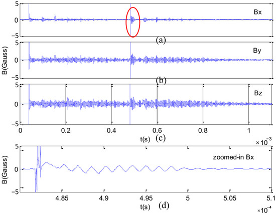
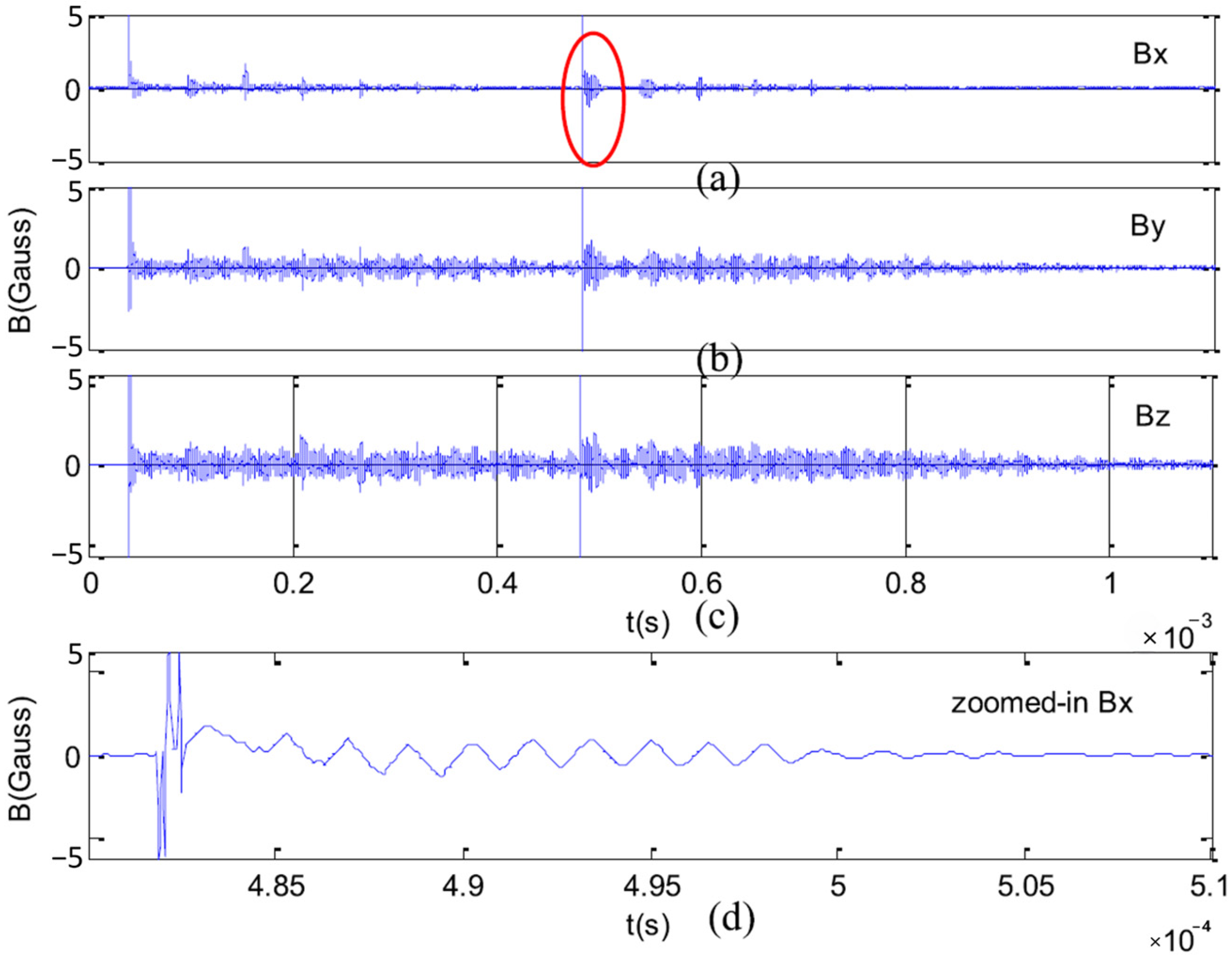
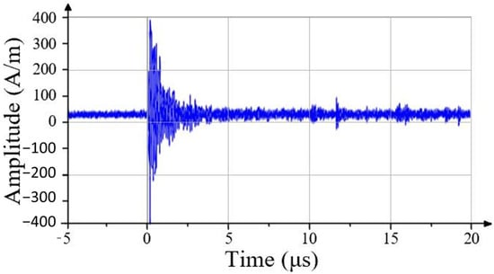
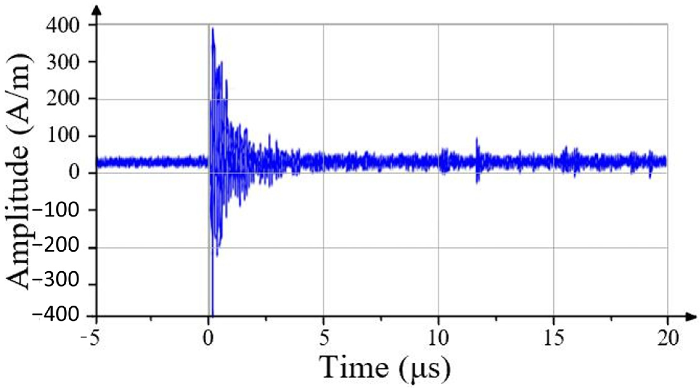
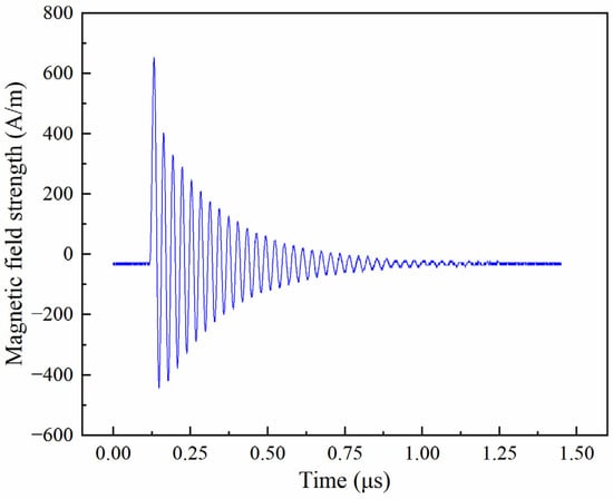
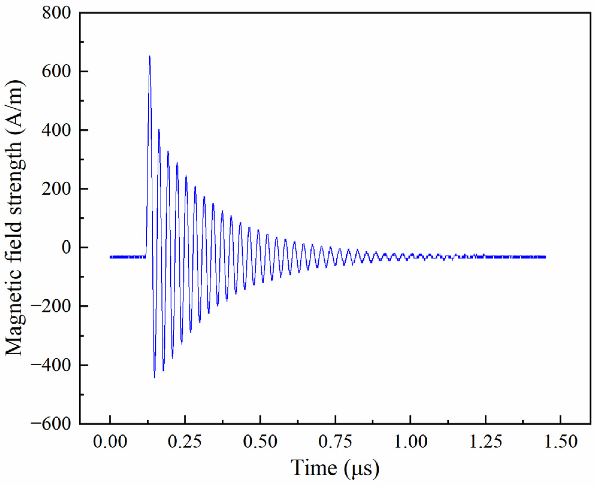
In this study, because the switching-induced TMF exhibits a bipolar damped oscillatory waveform, its amplitude is consistently described using the peak-to-peak magnetic-field strength Hpp, defined as Hpp = Hmax − Hmin. This definition is used throughout the following discussion unless otherwise specified. In terms of magnetic-field strength, the measured peak-to-peak TMF at a distance of 3 m from the bushing in a 110 kV GIS site is approximately 1000 A/m. As shown in Figure 1, the corresponding waveform exhibits a damped oscillatory form [12]. Near the current-transformer terminal box in a ±800 kV ultrahigh-voltage converter station, the measured TMF ranges approximately from −400 to +400 A/m, corresponding to a peak-to-peak magnetic-field strength of approximately 800 A/m, as shown in Figure 2 [13]. These data are far-field or mid-field measurements. If the actual deployment position of magnetic sensors close to primary conductors is considered, such as 10 cm from the central conductor inside GIS [16], the near-field TMF may reach several tens of mT according to the Biot–Savart law when the transient current reaches several kiloamperes. This value far exceeds the highest test level specified in the current standard IEC 61000-4-10 (1000 A/m ≈ 1.26 mT).
Figure 1.
TMF measured at a distance of 3 m from a GIS bushing in a 110 kV substation: (a) x-axis, (b) y-axis, and (c) z-axis; (d) enlarged view of the circled waveform in (a).
Figure 2.
TMF near the CT terminal box in a ±800 kV ultrahigh-voltage converter station.
The above analysis shows that TMF generated by substation switching operations has four defining characteristics. First, the waveform is a bipolar damped oscillation. Second, the characteristic frequencies relevant to the switching scenarios considered in this study span approximately 0.1 to 30 MHz. Third, the peak-to-peak magnetic-field strength can reach several hundred to nearly one thousand A/m. Fourth, the TMF occurs as pulse trains, and the amplitude envelope of each pulse follows a specific evolution pattern. These characteristics define the performance indicators required for a laboratory simulation device.
For waveform reproduction, the device should generate bipolar damped oscillatory magnetic fields over the 0.1–30 MHz range. This operating range is intended as a representative laboratory envelope for switching-operation TMF encountered around primary equipment in high-voltage substations: its lower-frequency portion covers disturbances associated mainly with AIS and circuit-breaker operations, whereas its MHz-to-tens-of-MHz portion represents the higher-frequency components typically observed during GIS disconnector operations. It is therefore not intended to define a universal frequency range for all substation configurations or switching conditions. Because the detailed waveform characteristics vary with voltage level, circuit configuration, and operating condition, the device should provide adjustable oscillation frequency and damping behavior. At the pulse-train level, the number of pulses, pulse interval, and peak-envelope mode should be programmable so that both the decaying envelope of closing operations and the increasing envelope of opening operations can be reproduced.
For magnetic-field strength, measured data indicate that switching-operation TMF at equipment-adjacent locations, such as GIS bushings and current-transformer terminal boxes, can reach several hundred A/m in peak-to-peak value. Accordingly, 800 A/m is adopted as a representative high-field laboratory target for magnetic sensors installed near primary equipment, rather than as a universal upper bound for switching-operation TMF. Extremely short-distance near-conductor locations, where substantially higher fields may occur, are outside the field-strength range represented by the present design target. Because the incident direction of the disturbance magnetic field significantly affects sensor response, the device should also provide adjustable magnetic-field direction.
3. TMF Waveform Reproduction Method and Simulation Device Design
3.1. Principle Design of the Magnetic-Field Generation Device
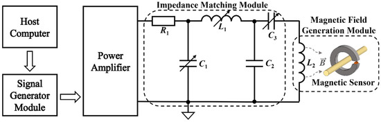
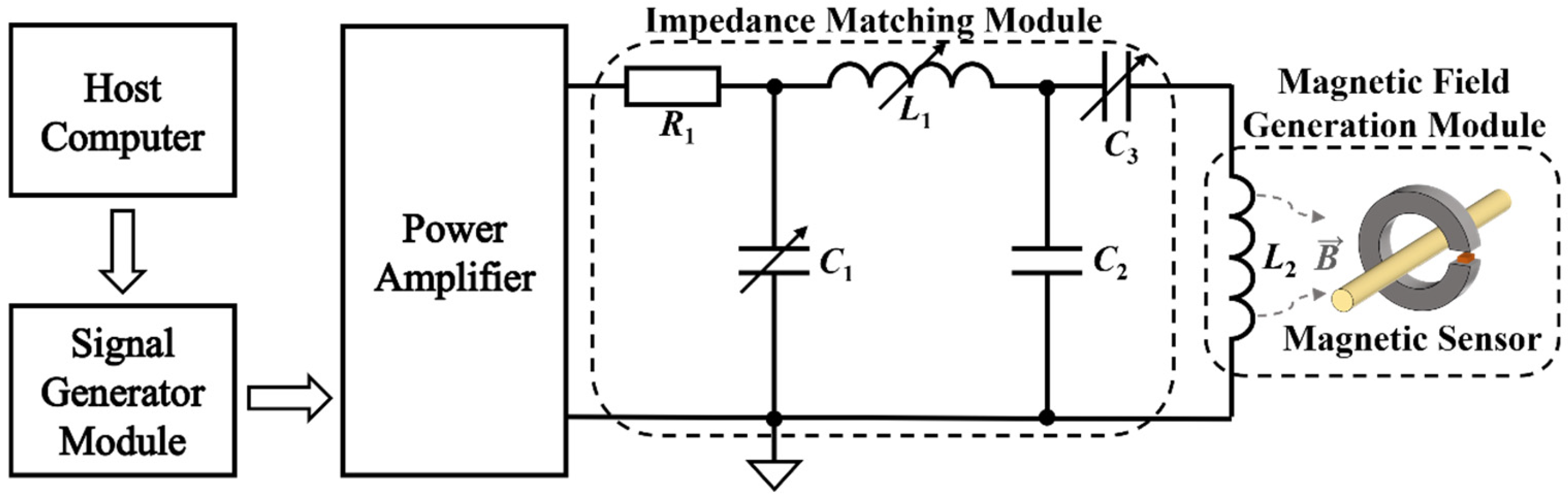
To satisfy the above TMF characteristic parameters and testing requirements for substation switching operations, a TMF simulation system for immunity testing of magnetic sensors was constructed, as shown in Figure 3. The system consists of four functional modules: a host computer, a signal-generation module, a magnetic-field generation module, and an impedance-matching module. These modules provide wideband operation, programmable waveform output, high-field-strength excitation, and adjustable field direction. Together, these functions enable laboratory reproduction of the waveform characteristics of TMF generated by substation switching operations. The host computer controls the signal-generation system and adjusts the waveform parameters. The signal-generation system produces simulated waveforms, including standard damped oscillatory single-pulse and pulse-train signals. In this study, an FPGA combined with a high-speed DAC is used to realize programmable waveform output and to accommodate different test-waveform requirements. The magnetic-field generation module amplifies the low-power signal from the signal generator to a power level sufficient to drive the magnetic-field generation coil L2 to the rated field strength. After power amplification, the high-frequency signal is transmitted to a high-frequency impedance-matching network composed of continuously adjustable capacitors C1 and C3, a selectable capacitor C2, and an adjustable inductor L1. This network corrects the transmission characteristics of the system, ensures impedance matching among the modules, and maximizes power transmission efficiency.
Figure 3.
Composition of the TMF simulation system for substation switching operations.
3.2. Design of the Magnetic-Field Generation Coil
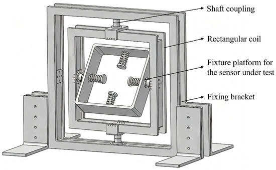
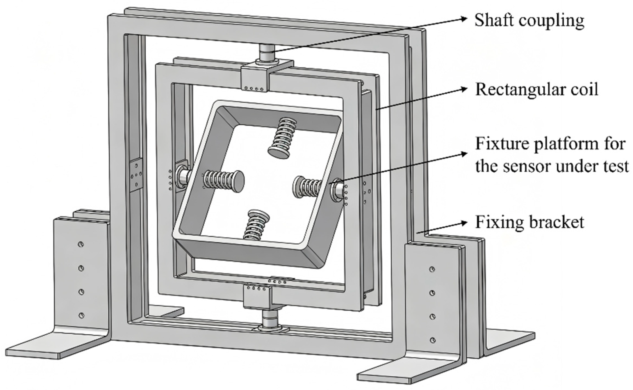
Most existing immunity test devices use a fixed Helmholtz-coil configuration [20,21]. Although this structure can excite magnetic-field components in the Bx, By, and Bz directions through a three-axis orthogonal arrangement, the rigidly connected coil frame cannot rotate around an arbitrary spatial axis. Consequently, the spatial orientation of the magnetic-field vector is limited to three discrete principal directions, which makes it difficult to reproduce the time-varying oblique-incidence magnetic-field characteristics of switching-operation TMF. To meet the requirements of omnidirectional immunity testing for magnetic sensors, this study designs a rectangular magnetic-field generation coil, as shown in Figure 4, and adopts a multidirectional rotating mechanical configuration based on a cross-nested coupling mechanism. In this structure, the rectangular coil can independently rotate through an angular deflection of ±180° around the fixed X-axis, whereas the test platform carrying the magnetic sensor can independently rotate through an angular deflection of ±180° around the Y-axis. With servo-motor actuation, the system achieves a rotational positioning accuracy within 0.1°, which improves the flexibility and coverage of test orientations. As a result, the TMF generated by the test device can be adjusted over 360° and used to conduct more comprehensive immunity testing of the magnetic sensor under test.
Figure 4.
Mechanical structure of the generation coil with a fully adjustable TMF direction.
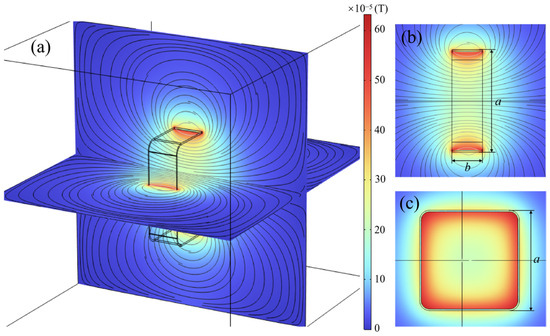
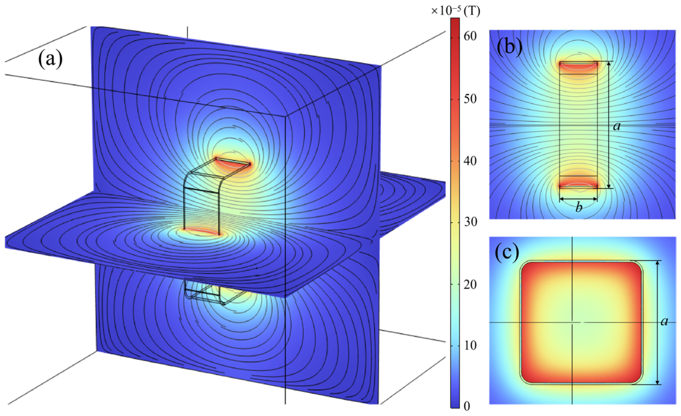
A uniformly wound multi-turn rectangular coil model was constructed in COMSOL Multiphysics 6.3 (COMSOL AB, Stockholm, Sweden), and finite-element analysis was performed to evaluate the spatial distribution of the magnetic field inside the coil. A stationary magnetic-field study was adopted without introducing an excitation frequency, with the aim of assessing the field uniformity determined by the coil geometry under steady-state excitation. The coil was modeled as a nonmagnetic copper conductor with 40 turns and an excitation current amplitude of 2 A. A sufficiently large surrounding air domain was used to minimize the influence of the outer boundary, and the stationary magnetic-field equations were solved in COMSOL. As shown in Figure 5, the simulation results indicate good magnetic-field uniformity in the central region of the rectangular coil. Within the central region of the coil, extending approximately a/3 in the width direction and 2b/3 in the depth direction, where a and b denote the coil side length and frame thickness, respectively, the spatial variation in magnetic-field strength remains within 5%. The magnetic-field lines further show that the dominant field direction in the central region is approximately perpendicular to the coil plane, indicating good directional consistency. It should be noted that these results characterize the spatial magnetic-field distribution under the specified stationary simulation condition. To assess the magnetic-field uniformity over the full operating frequency range of 0.1–30 MHz, the spatial field distribution of the coil under high-frequency excitation requires further experimental evaluation.
Figure 5.
Simulated magnetic-field distribution inside a rectangular uniform multi-turn coil: (a) 3D cross-section of magnetic flux density; (b) side view; (c) top view.
Based on the preliminary structural analysis and simulated spatial field distribution, the side length of the rectangular coil frame was determined to be 350 mm and the frame thickness was set to 60 mm. These dimensions provide a sufficiently large central working region for the placement of magnetic sensors while maintaining a compact coil structure. The detailed winding configuration was further determined during the subsequent hardware design according to the required magnetic-field strength and high-frequency excitation capability.
3.3. Design of the Magnetic-Field Generation and Impedance-Matching Network
Following the determination of the coil geometry and frame dimensions through the preliminary simulation in Section 3.2, the winding configuration was further designed according to the required magnetic-field strength and high-frequency excitation capability of the practical system. The 40-turn winding adopted in the preliminary model served as an initial configuration for evaluating the spatial field distribution during the structural-design stage, whereas the number of turns was not treated as the final hardware parameter. In the subsequent practical design, the turn number and winding arrangement were further optimized to increase the magnetic-field generation capability while maintaining suitable high-frequency excitation characteristics. Accordingly, the fabricated rectangular coil was wound with Litz wire and consisted of 88 turns arranged in four tightly wound layers, with 22 turns per layer. The wire consists of 250 stranded conductors, with a conductor cross-sectional area of 1.96 mm2 and an outer diameter of d = 2.21 mm. The use of Litz wire helps reduce the influence of skin and proximity effects under high-frequency excitation.
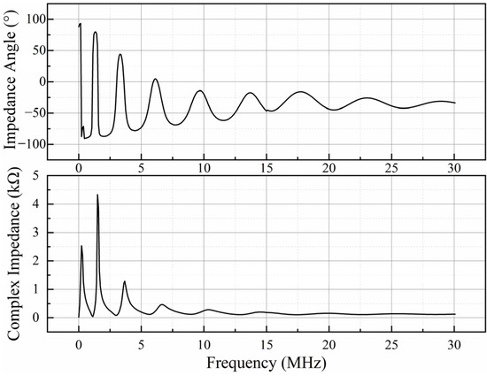
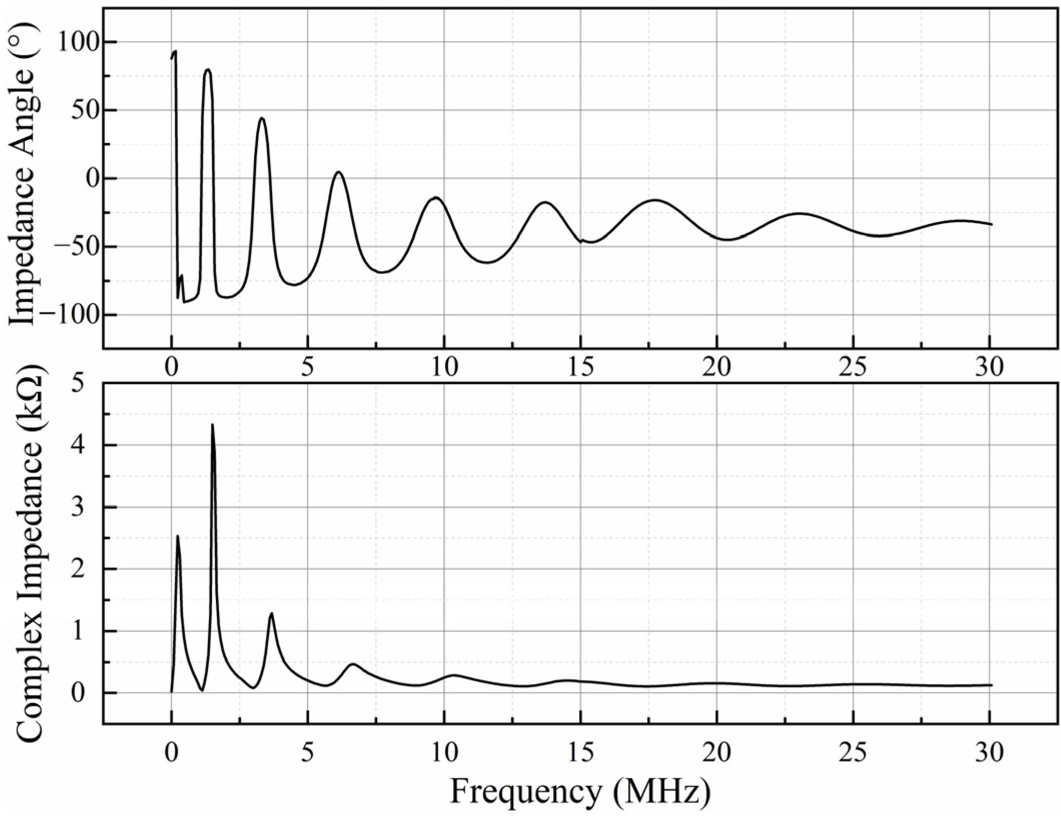
Because the electrical characteristics of the multi-turn coil are affected by winding inductance, parasitic capacitance, inter-turn and inter-layer coupling, and frequency-dependent conductor losses, its high-frequency impedance cannot be adequately represented by a single frequency-independent impedance value. Therefore, the actual frequency-dependent impedance of the fabricated coil was characterized experimentally using an E5063A vector network analyzer (Keysight Technologies, Santa Rosa, CA, USA). Figure 6 shows the measured impedance magnitude and phase over the operating frequency range. The results exhibit pronounced frequency dependence and multiple resonance features, demonstrating the necessity of broadband impedance compensation for high-frequency excitation.
Figure 6.
Frequency-sweep characteristics of the complex impedance and impedance angle of the high-frequency magnetic-field generation coil.
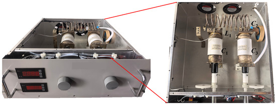
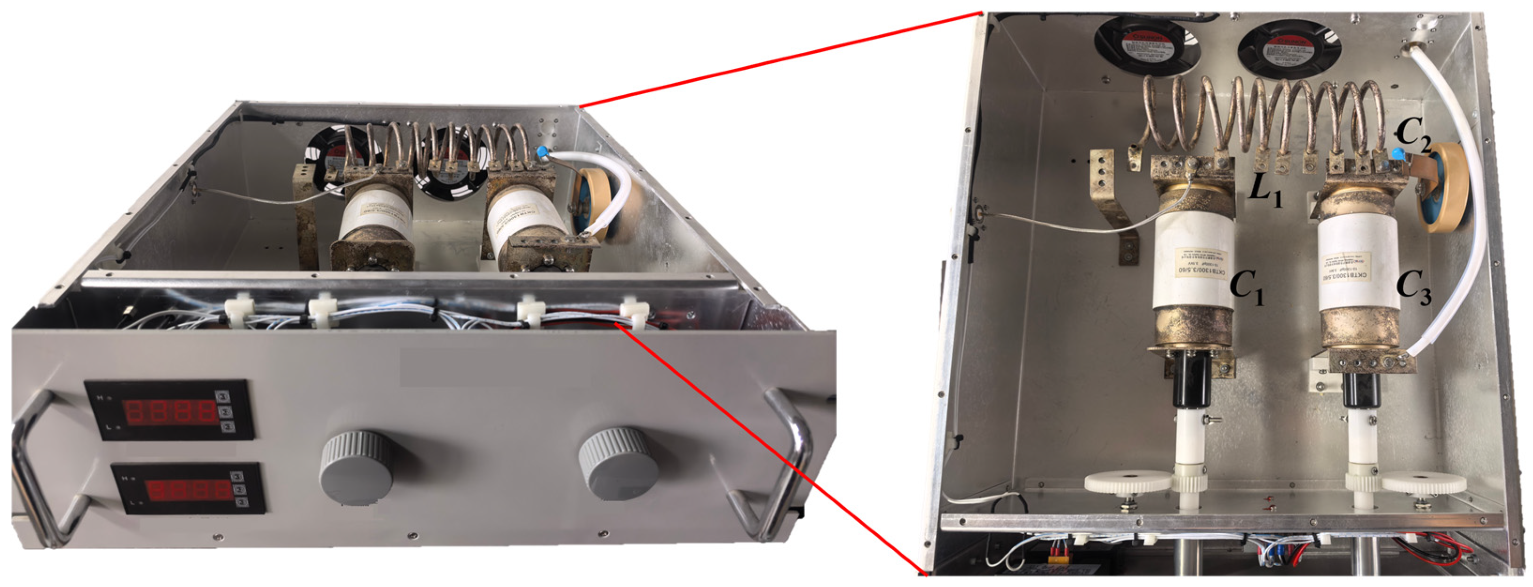
Accordingly, the adjustable impedance-matching circuit shown in Figure 3 was connected between the power amplifier and the magnetic-field generation coil. By adjusting the matching components at different operating frequencies, the reactive component of the coil impedance can be compensated, thereby reducing impedance mismatch and improving power-transfer efficiency. Figure 7 shows the developed adjustable impedance-matching device.
Figure 7.
Adjustable wideband impedance-matching device.
The adjustable impedance-matching network adopts a coarse–fine tuning strategy. C1 and C3 are continuously adjustable capacitors with capacitance ranges of 10–1300 pF and are controlled by the two front-panel knobs shown in Figure 7. C2 is a selectable mica capacitor with available capacitance values of 600, 1000, 1600, 2000, 3000, and 4000 pF, while L1 is a tapped air-core inductor with selectable inductance values ranging from approximately 0.66 to 25.58 μH. C2 and L1 are used for coarse internal adjustment, whereas C1 and C3 are used for continuous fine adjustment. The matching network can accommodate load impedances with a resistive component of approximately 2–45 Ω and a reactive component with a magnitude of up to approximately 70 Ω.
At each operating frequency, the approximate coil impedance is first measured to determine suitable coarse settings of L1 and C2. The power amplifier is then enabled, and C1 and C3 are fine-tuned while the forward and reflected powers are monitored. A forward-to-reflected power ratio of at least 10:1 is used as the practical matching criterion. The corresponding return loss is calculated as:
where Pf and Pr are the measured forward and reflected powers, respectively. Thus, Pf/Pr ≥ 10 corresponds to RL ≥ 10 dB. For commonly used frequency points, the corresponding L1, C2, C1, and C3 settings are recorded and reused as initial settings for subsequent tests, requiring only minor fine adjustment of C1 and C3.
Dynamic adjustment of the matching components compensates for the frequency-dependent reactive impedance of the coil and transforms the load impedance seen by the 50 Ω power amplifier toward the required matching condition, thereby reducing reflected power. Table 2 lists the coil impedance measured directly at the coil terminals, the matched input impedance measured at the input of the matching-network–coil assembly, and the corresponding forward and reflected powers at representative frequencies.
Table 2.
Coil impedance characteristics and matching performance at representative frequencies.
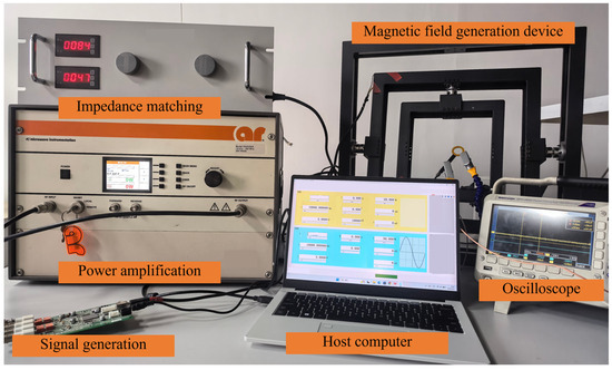
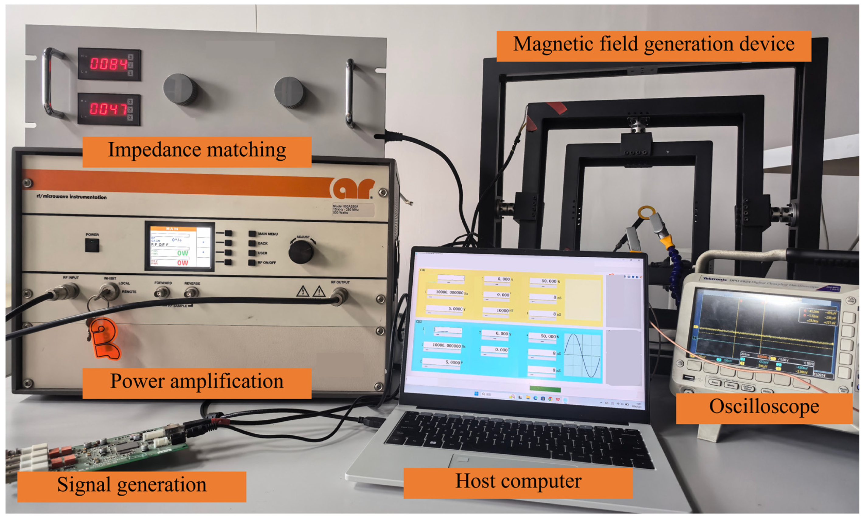
Figure 8 shows the TMF simulation system constructed for immunity testing of magnetic sensors under substation switching-operation disturbances. Combined with an AR Model 500A250A high-frequency high-power amplifier (AR RF/Microwave Instrumentation, Souderton, PA, USA) and the self-developed adjustable impedance-matching device, the system can generate a high-frequency disturbance magnetic field with a maximum strength of 800 A/m in the central region of the coil over a frequency band of 0.1 to 30 MHz. Under host-computer control, the characteristic parameters of the generated TMF can be adjusted within a defined range, and the direction of the applied magnetic field can be changed conveniently during sensor testing. These functions support more comprehensive immunity testing of the magnetic sensor under test.
Figure 8.
Photograph of the TMF simulation system for substation switching-operation disturbances.
4. Performance Verification of the Test Platform
4.1. Measurement Setup, Field-Strength Determination, and Uncertainty
Two complementary measurement methods were employed to characterize the output of the TMF generation system. The current flowing through the magnetic-field generation coil was measured using a CT6701 wideband current probe (HIOKI E.E. Corporation, Ueda, Japan). The probe has a bandwidth of DC–120 MHz, a nominal output sensitivity of 1 V/A, and a rise time of no more than 2.9 ns. Its output was recorded using a DSOX4054A digital oscilloscope (Keysight Technologies, Santa Rosa, CA, USA) with a bandwidth of 500 MHz and a maximum sampling rate of 5 GSa/s. The bandwidth and temporal response of this measurement chain are sufficient for resolving the 0.1–30 MHz oscillatory signals considered in this study.
The peak-to-peak magnetic-field strength at the geometric center of the fabricated coil was determined from the measured coil current. Based on the Biot–Savart law, the current-to-field relationship for the 88-turn rectangular coil is expressed as
where Ipp is the measured peak-to-peak coil current, N = 88 is the number of turns, and aeff is the effective mean centerline side length of the fabricated winding. For aeff ≈ 0.350 m, the nominal current-to-field conversion coefficient is KI ≈ 226.4 m−1. The applicability of this coefficient was additionally checked at representative frequencies of 0.1, 1, 3, 10, 20, and 30 MHz using an independent frequency-point calibration. The experimentally determined coefficients ranged from 219.8 to 241.9 m−1, corresponding to deviations of −2.92% to 6.85% from the nominal value. In particular, the deviations at 20 and 30 MHz were −2.92% and −2.69%, respectively, indicating that no systematic deterioration of the current-to-field relationship occurred toward the upper end of the operating range. The nominal coefficient was therefore retained for the current-based field-strength determination, with the observed coefficient variation incorporated into the uncertainty evaluation.
The temporal characteristics of the generated magnetic field were independently verified using HNFP-5 and HNFP-7 passive magnetic near-field probes manufactured by Qingdao Hantek Electronic Co., Ltd. (Qingdao, China). The HNFP-7 covers 9 kHz–1.5 MHz and the HNFP-5 covers 1–50 MHz. Since these probes were used for relative waveform verification rather than absolute field-strength calibration, their outputs were normalized when evaluating the oscillation frequency, damping behavior, and waveform shape. During the measurements, the probe was fixed at the geometric center of the energized coil and oriented for maximum response to the magnetic field normal to the coil plane. No sensor under test or other object was placed in the central working region.
Each operating condition was measured repeatedly 5 times, and the field-strength uncertainty was estimated from the current-probe measurement, oscilloscope amplitude measurement, current-to-field conversion coefficient, and measurement repeatability. The principal uncertainty contributions are summarized in Table 3. Assuming the individual contributions to be independent, the combined relative standard uncertainty is approximately 6.0%, corresponding to an expanded uncertainty of approximately 12.0% for k = 2.
Table 3.
Estimated uncertainty contributions for magnetic-field strength determination.
4.2. Spatial Field Uniformity Verification
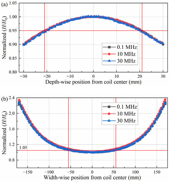
To verify the magnetic-field uniformity of the fabricated coil under actual high-frequency operation, the spatial field distribution of the final 88-turn coil was experimentally measured at 0.1, 10 and 30 MHz after impedance matching. The complete generation chain, including the power amplifier, impedance-matching network, and fabricated coil, was maintained in the same operating configuration as that used for the waveform measurements.
The magnetic near-field probe was moved along the depth-wise and width-wise centerlines of the coil while its orientation relative to the magnetic field was kept unchanged. Since the measurements were performed at a fixed frequency using the same probe and acquisition configuration, the measured peak-to-peak probe output at each position was normalized to that at the geometric center of the coil. The normalized field strength was therefore expressed as
where Vpp(s) is the peak-to-peak probe output at position s, and Vpp(0) is the corresponding value at the coil center. Since the measurements are normalized independently at each frequency, the results are used to compare the spatial field-distribution characteristics rather than the absolute field amplitudes at different frequencies.
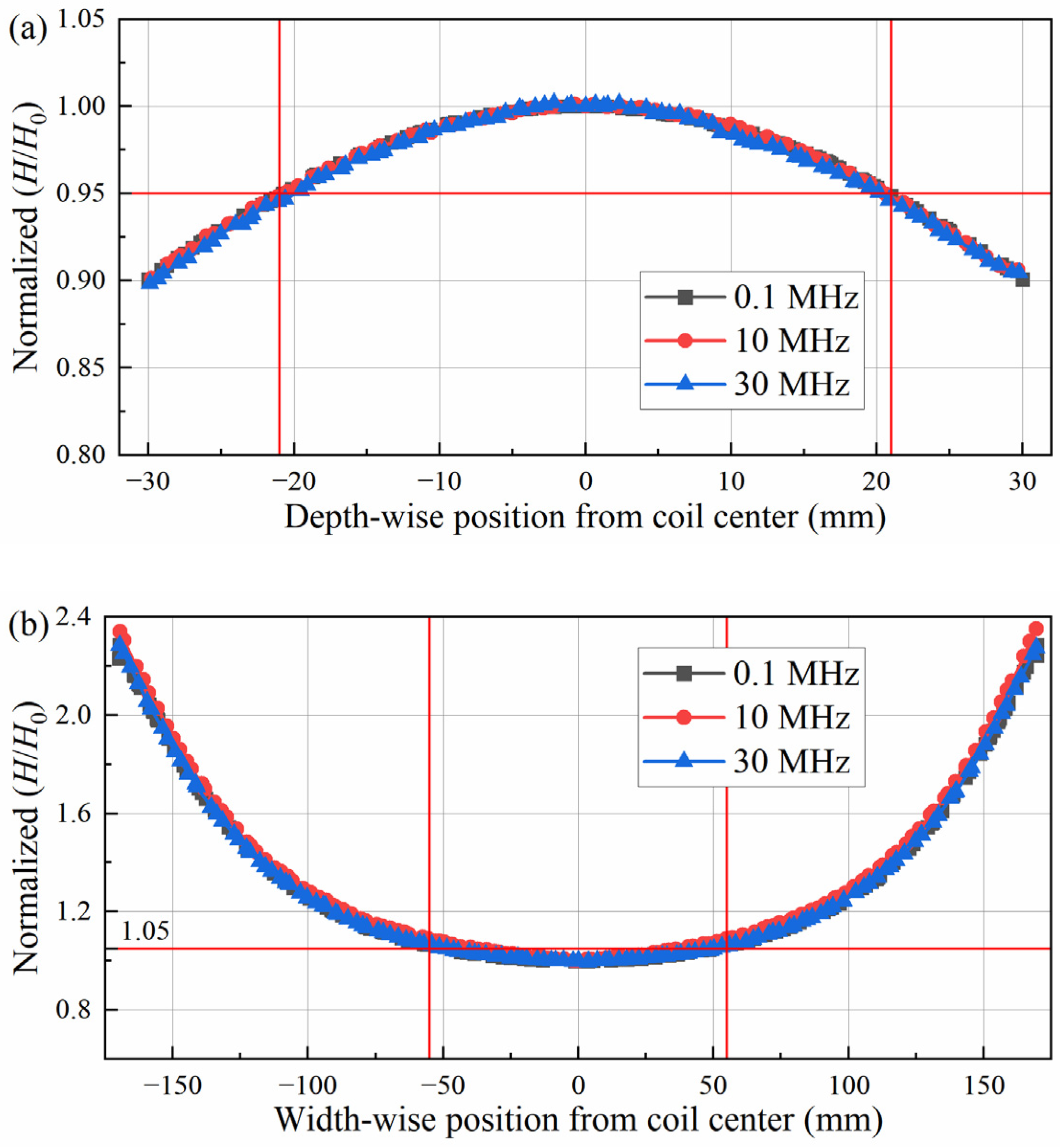
Figure 9 shows the normalized magnetic-field distributions along the depth-wise and width-wise directions at 0.1, 10, and 30 MHz. The three sets of curves exhibit highly consistent spatial trends, with only small differences among the representative frequencies. In the depth direction, the deviation from the center value remains within 5% over approximately −21 to +21 mm. In the width direction, the corresponding 5% criterion is satisfied over approximately −55 to +55 mm. Therefore, an effective central working region of approximately 110 mm × 42 mm is maintained at all three representative frequencies.
Figure 9.
Normalized magnetic-field-strength distributions of the fabricated coil at representative frequencies of 0.1, 10, and 30 MHz after impedance matching: (a) depth-wise distribution; (b) width-wise distribution.
The results demonstrate that the fabricated coil maintains stable spatial magnetic-field uniformity at representative low, intermediate, and high-frequency operating conditions, providing experimental support for the spatial field performance of the device over the investigated frequency range.
4.3. Output Waveform and Field-Strength Verification
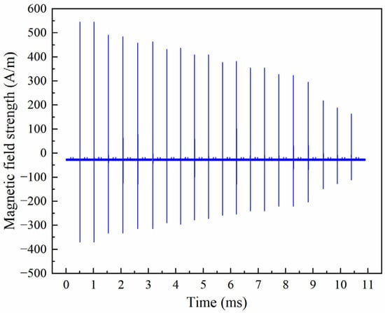
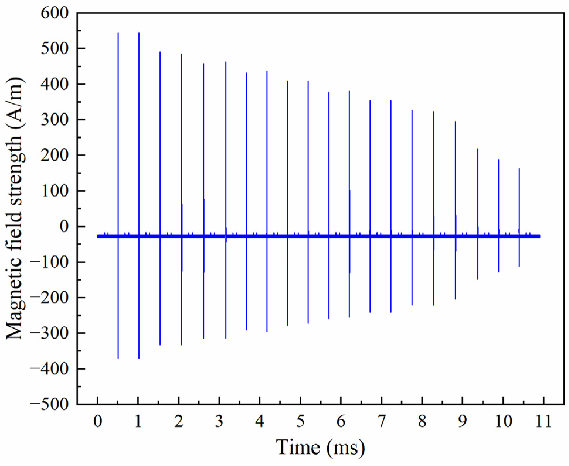
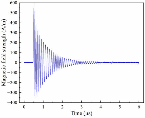
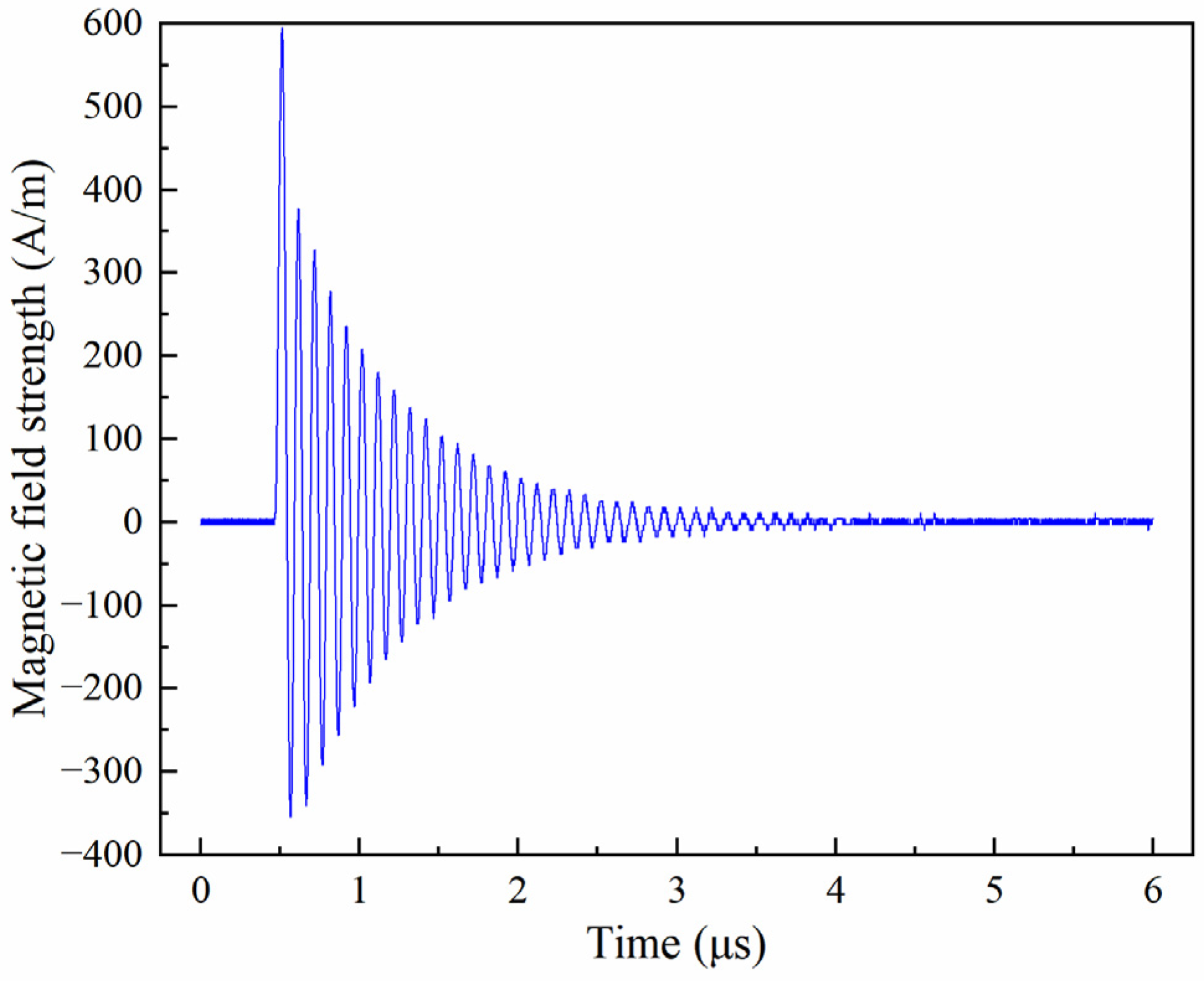
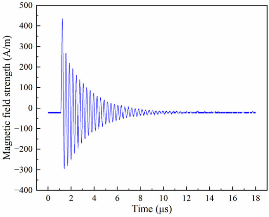
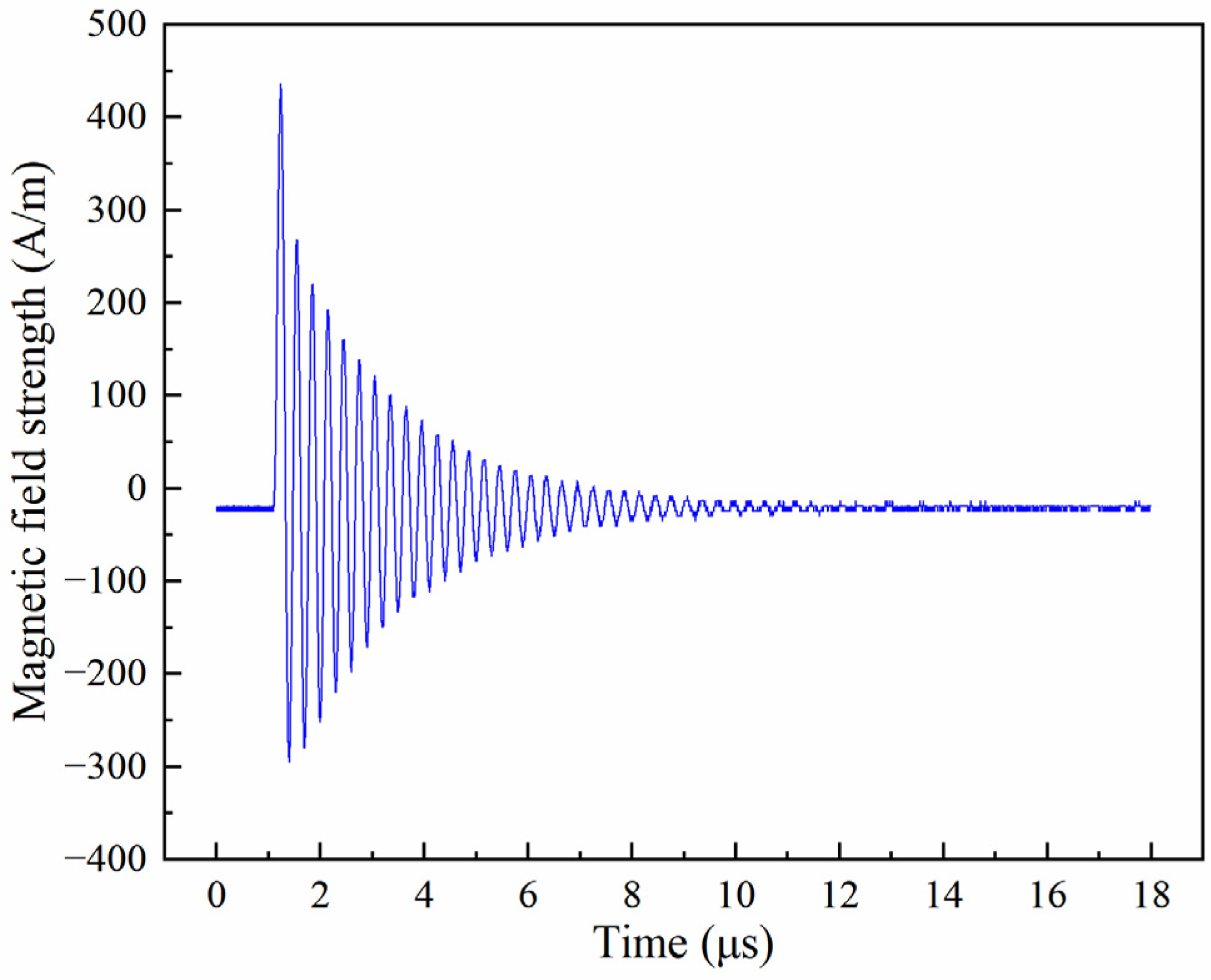
The measurements were performed with no sensor under test or other object placed in the central working region of the energized rectangular coil. Figure 10 shows the pulse-train waveform generated by the device at 10 MHz. The pulse train lasts 10 ms and contains 20 bipolar damped oscillatory pulses with a pulse interval of 0.5 ms. The peak envelope exhibits the closing-operation characteristic, in which the first pulse has the largest amplitude and the subsequent pulses decrease successively. The measured peak-to-peak magnetic-field strength exceeds 800 A/m, demonstrating that the designed field-strength target can be achieved while maintaining the required pulse-train waveform.
Figure 10.
Pulse-train waveform of a 10 MHz bipolar damped oscillatory TMF.
Figure 11 presents an expanded view of a single pulse at 10 MHz. The waveform exhibits a typical bipolar damped oscillatory form, while the peak-to-peak magnetic-field strength remains above the 800 A/m design target. The measured rise time is approximately 15 ns, and the single-pulse duration is approximately 5 μs. The oscillation amplitude decreases to approximately 50% of its initial value after about five cycles, which is consistent with the waveform characteristics summarized in Section 2. Figure 12 and Figure 13 show representative single-pulse waveforms at 3 and 30 MHz, respectively. Their waveform forms are consistent with that observed at 10 MHz, and the measured oscillation frequencies are consistent with the corresponding preset frequencies. In accordance with the characteristic-parameter-equivalence approach adopted in this study, reproduction performance is evaluated from the measured waveform form, oscillation frequency, damping characteristics, pulse-train parameters, and magnetic-field strength, rather than from point-by-point agreement with a single reference waveform.
Figure 11.
Single-pulse waveform of a 10 MHz bipolar damped oscillatory TMF.
Figure 12.
Single-pulse waveform of a 3 MHz bipolar damped oscillatory TMF.
Figure 13.
Single-pulse waveform of a 30 MHz bipolar damped oscillatory TMF.
Figure 11, Figure 12 and Figure 13 demonstrate the stable generation of bipolar damped oscillatory magnetic fields at representative frequencies. The differences in the displayed amplitudes mainly arise from the frequency-dependent gain of the power amplifier and the corresponding impedance-matching conditions. The magnetic-field strength can be continuously adjusted by varying the excitation level under the corresponding matched condition, and a peak-to-peak field strength of approximately 800 A/m has been achieved in the field-strength performance verification. The quantitative field strength is determined from the measured coil current according to the current-to-field conversion method described in Section 4.1.
The device output can be flexibly configured through the FeelTech V7.8 host-computer software, including the oscillation frequency, number of pulses, pulse interval, and peak-envelope mode. The overall duration of a pulse train consequently depends on the selected pulse number, interval, and waveform settings. The test results demonstrate controllable oscillation frequency and damping characteristics, together with programmable pulse-train parameters. These capabilities enable laboratory reproduction of the principal temporal characteristics of switching-operation TMF. The main adjustable output parameters of the developed system are summarized in Table 4.
Table 4.
Principal characteristic parameters and adjustable output ranges of the developed TMF generation system.
4.4. Comparison with the Standardized Damped-Oscillatory Magnetic-Field Test
We further compared the measured performance of the developed system with the standardized damped-oscillatory magnetic-field immunity test specified in IEC 61000-4-10. This standard specifies repetitive damped oscillatory magnetic fields at 0.1 and 1 MHz, with the oscillation amplitude decreasing to 50% of the peak value within 3–6 cycles. The preferred field-strength levels are 10, 30, and 100 A/m (peak), with an additional open level X. The corresponding repetition rates are at least 40 transients/s at 0.1 MHz and 400 transients/s at 1 MHz.
IEC 61000-4-10 provides a reproducible standardized test condition for damped oscillatory magnetic disturbances associated with medium- and high-voltage substations. The system developed in this work retains the same basic damped-oscillatory waveform form but extends laboratory reproduction to broader characteristics extracted from switching-operation TMF. As verified in the preceding sections, the oscillation frequency is adjustable from 0.1 to 30 MHz, while the pulse number, pulse interval, damping characteristics, and pulse-train peak-envelope evolution can be programmed. In addition, the magnetic-field direction can be mechanically adjusted over 360°. The main differences are summarized in Table 5. Based on the above comparison, the TMF simulation system developed in this work is not intended to replace the standardized IEC test, but to extend laboratory reproduction toward the wider frequency range, programmable pulse-train characteristics, and variable field directions observed in switching-operation TMF.
Table 5.
Comparison between IEC 61000-4-10 and the developed TMF generation system.
5. Conclusions
To meet the requirements for evaluating the immunity of magnetic sensors under TMF generated by substation switching operations, this study proposes a TMF waveform reproduction method based on characteristic-parameter equivalence and develops a corresponding magnetic-field simulation test device. Measured and simulated data reported in the literature are used to systematically summarize the time-domain, frequency-domain, and field-strength characteristics of switching-operation TMF. For the pulse-train waveform form of bipolar damped oscillation, a target reproduction frequency range of 0.1–30 MHz is selected based on the reported switching-transient characteristics, and a field-strength target of not less than 800 A/m is clarified, thereby providing a quantitative basis for waveform reproduction. On this basis, a TMF simulation system based on FPGA programmable waveform generation and high-frequency power amplification is designed. A multidirectional rotating configuration combining a rectangular coil with a cross-nested coupling mechanism is adopted to achieve 360° omnidirectional adjustability of the magnetic-field direction, and a broadband impedance-matching network is developed to ensure stable output over the 0.1 to 30 MHz frequency range. The test results show that the device can output bipolar damped oscillatory TMF with a reachable peak-to-peak magnetic-field strength of not less than 800 A/m within this frequency range. The pulse-train parameters and oscillation frequency can be flexibly configured, enabling laboratory reproduction of the TMF waveform characteristics generated by substation switching operations. The developed system provides a controllable wideband TMF generation platform for laboratory reproduction of switching-operation magnetic disturbances and establishes the experimental basis for subsequent immunity studies of magnetic sensors. Future work will focus on the mechanism of sensor performance degradation under the superposed effects of multi-source magnetic fields and on the standardization of related test methods.
Author Contributions
Conceptualization, F.L. and C.L.; methodology, C.L.; software, G.M.; validation, L.H., F.L. and A.Y.; investigation, C.L., A.Y., G.M. and X.W.; data curation, C.L.; writing—original draft preparation, C.L., F.L. and G.M.; writing—review and editing, C.L. and Q.S.; visualization, F.L., L.H., C.L., G.M., A.Y. and X.W. All authors have read and agreed to the published version of the manuscript.
Funding
This work was funded by the State Grid Sichuan Electric Power Company Science and Technology Project (Project No.52199923001G).
Data Availability Statement
The data that support the findings of this study are available from the corresponding author upon reasonable request. The data are not publicly available due to institutional restrictions on the disclosure of project-related data and proprietary technical information associated with the experimental system.
Conflicts of Interest
The authors declare that the research was conducted in the absence of any commercial or financial relationships that could be construed as potential conflicts of interest.
Abbreviations
The following abbreviations are used in this manuscript:
| TMF | Transient Magnetic Field |
References
- Yu, J.; Long, Z.; Liang, S.; Yue, C.; Yin, X.; Zhou, F. Optimal design of dual air-gap closed-loop TMR current sensor based on minimum magnetic field uniformity coefficient. Sci. Rep. 2023, 13, 1268. [Google Scholar] [CrossRef] [Scilit]
- Ouyang, Y.; Wang, Z.; Zhao, G.; Hu, J.; Ji, S.; He, J.; Wang, S.X. Current sensors based on GMR effect for smart grid applications. Sens. Actuators A Phys. 2019, 294, 8–16. [Google Scholar] [CrossRef] [Scilit]
- Xu, Y.; Jin, Z.H.; Chen, J.M. High-precision tunneling magnetoresistance (TMR) current sensor for weak current measurement in smart grid applications. Micromachines 2025, 16, 136. [Google Scholar] [CrossRef] [Scilit]
- Huang, Q.; Khawaja, A.H.; Chen, Y.; Li, J. Magnetic field measurement for modern substations. In Magnetic Field Measurement with Applications to Modern Power Grids; Huang, Q., Khawaja, A.H., Chen, Y., Li, J., Eds.; Wiley-IEEE Press: Hoboken, NJ, USA, 2019; pp. 143–218. [Google Scholar] [CrossRef] [Scilit]
- Ma, H.; Wu, S.; Bi, R.; Zhang, H.; Tian, J.; Zhang, D.; Hu, J. Elliptical arrays of tunnelling magnetoresistance sensors for rectangular busbar current measurement. High Volt. 2025, 10, 807–819. [Google Scholar] [CrossRef] [Scilit]
- Zhao, J.; Chen, W.; Zhang, J.; Xia, Y.; He, W.; Li, K. Simulation of electromagnetic fields emitted from GIS bushing due to disconnectors switching operation in 1000 kV substations. CSEE J. Power Energy Syst. 2025, 11, 1963–1971. [Google Scholar] [CrossRef] [Scilit]
- Wang, P.; Huang, W.; Su, H.; Li, J.; Xie, B.; Qiu, J.; Shi, B.; Zhang, Y.; Zhou, X.; Guo, T.; et al. Laser diode-in-capacitors for high-voltage line non-contact monitoring: Voltage, electromagnetic interference and vibration monitoring. High Volt. 2025, 10, 1302–1313. [Google Scholar] [CrossRef] [Scilit]
- Li, Q.; Gao, K.; Yang, Z.; Ju, Y.; Hu, C. Transient electromagnetic interference characteristics and influential factors of wireless sensor nodes in intelligent substations. IEEE Sens. J. 2025, 25, 42091–42101. [Google Scholar] [CrossRef] [Scilit]
- Wu, H.; Jiao, C.; Cui, X.; Liu, X.; Ji, J. Transient electromagnetic disturbance induced on the ports of intelligent component of electronic instrument transformer due to switching operations in 500 kV GIS substations. IEEE Access 2017, 5, 5104–5112. [Google Scholar] [CrossRef] [Scilit]
- Wang, Q.; Fu, C.; Chu, F.; Tong, Y.; Wang, X.; Ye, G.; Wu, X. A quantitative research on the level of disturbance to secondary signal ports of electronic voltage transformers under the operation of gas-insulated switchgear. High Volt. 2022, 7, 165–175. [Google Scholar] [CrossRef] [Scilit]
- Luo, Y.; Yang, L.; Cheng, L.; Wu, J.; Gu, Y. Research of electromagnetic transient characteristics in substations due to disconnector switching. High Volt. Eng. 2024, 50, 1801–1811. [Google Scholar] [CrossRef]
- Huang, Q.; Wang, X.; Zhen, W.; Pong, P.W.T. Broadband point measurement of transient magnetic interference in substations with magnetoresistive sensors. IEEE Trans. Magn. 2014, 50, 6200505. [Google Scholar] [CrossRef] [Scilit]
- Liu, G.; Yue, X.; Yang, J.; Yuan, J.; Wen, B.; Gao, W. Electromagnetic environment under switching operation in different high-voltage substation. In Proceedings of the 2023 6th International Conference on Electrical Engineering and Green Energy (CEEGE), Grimstad, Norway, 8–10 June 2023; pp. 91–94. [Google Scholar] [CrossRef] [Scilit]
- Wang, S.; Wang, Z.; Hu, J.; Ouyang, Y.; Yuan, Z.; He, J. Ontology and anti-interference design of current sensor with high voltage, wide frequency band and large current based on giant magneto resistive effect. High Volt. Eng. 2016, 42, 1715–1723. [Google Scholar] [CrossRef]
- Hu, X.; Duan, X.; Zhang, W.; Fu, Y.; Li, Y.; Zhao, P.; Deng, X.; Yu, C.; Wang, J. Design and optimization of multi-stage TMR sensors for power equipment AC/DC leakage current detection. Sensors 2023, 23, 4749. [Google Scholar] [CrossRef] [Scilit]
- Khawaja, A.H.; Huang, Q.; Chen, Y. A novel method for wide range electric current measurement in gas-insulated switchgears with shielded magnetic measurements. IEEE Trans. Instrum. Meas. 2019, 68, 4712–4722. [Google Scholar] [CrossRef] [Scilit]
- Li, S.; Huang, S.; Liu, L.; Su, Q.; Zeng, G.; Wu, T. Accurately evaluate anti-magnetic field interference ability: A study on magnetic field interference degree analysis method for magnetic sensors. Sens. Actuators A Phys. 2024, 372, 115029. [Google Scholar] [CrossRef] [Scilit]
- Wu, H.; Jiao, C.; Cui, X. Study on coupling of very fast transients to secondary cable via a test platform. IEEE Trans. Electromagn. Compat. 2018, 60, 1366–1375. [Google Scholar] [CrossRef] [Scilit]
- Yang, T.; Huang, L.; Wu, J.; Huang, J.; Pang, W.; Wu, X. Experimental research of electromagnetic interference caused by disconnector operation in gas insulated switchgear. IOP Conf. Ser. Mater. Sci. Eng. 2019, 486, 012096. [Google Scholar] [CrossRef] [Scilit]
- Liu, X.; Xing, L.; Xu, Q.; Shen, X.; Chen, K. A compact 3D Helmholtz coil designed for EMC testing. In Proceedings of the 2022 IEEE MTT-S International Microwave Workshop Series on Advanced Materials and Processes for RF and THz Applications (IMWS-AMP), Guangzhou, China, 27–29 November 2022; pp. 1–3. [Google Scholar] [CrossRef] [Scilit]
- Fontanet, A.; Marcos, J.; Ribó, L.; Massana, V.; Campmany, J. Design and construction of 3D Helmholtz coil system to calibrate 3D Hall probes. J. Phys. Conf. Ser. 2019, 1350, 012167. [Google Scholar] [CrossRef] [Scilit]

Disclaimer/Publisher’s Note: The statements, opinions and data contained in all publications are solely those of the individual author(s) and contributor(s) and not of MDPI and/or the editor(s). MDPI and/or the editor(s) disclaim responsibility for any injury to people or property resulting from any ideas, methods, instructions or products referred to in the content. |
© 2026 by the authors. Licensee MDPI, Basel, Switzerland. This article is an open access article distributed under the terms and conditions of the Creative Commons Attribution (CC BY) license.