


Abstract
Conventional proportional integral (PI) current controllers used in field-oriented control (FOC) have an acceptable performance under linear motor models, but their performance degrades when nonlinear machine characteristics are taken into account. This paper presents a comparative evaluation of PI and twin delayed deep deterministic policy gradient (TD3)-based current control for a permanent magnet synchronous motor (PMSM) drive using a high-fidelity nonlinear motor model. The first step involves modeling and validating a PMSM in JMAG using finite element analysis, assessing its electromagnetic properties. Subsequently, JMAG-RT is utilized to generate nonlinear flux, torque, and inductance maps, which are implemented as lookup tables (LUTs) in MATLAB/Simulink (R2026a) to accurately capture the motor’s nonlinear behavior. Then, the performance of both the PI and TD3 controllers is tested with both lumped-parameter and nonlinear motor models. The results show that the PI controller has strong speed oscillation and current fluctuation under nonlinear operating conditions, but the TD3-based controller has better tracking accuracy and current regulation performance. In terms of integral absolute error (IAE), compared to PI-based nonlinear motor parameters, the TD3 control framework provides a 17.6% reduction in speed IAE, and a minor 0.4% decrease in q-axis current IAE, resulting in accurate reference tracking under nonlinear operating conditions. These findings demonstrate the effectiveness of reinforcement learning for enhancing the performance of PMSM drives when high-fidelity nonlinear motor models are considered.
1. Introduction
Modern industrial automation, transportation, and energy conversion systems are based on electric machines. As the process of electrification, especially in electric vehicles, robotics, and renewable energy systems, is rapidly growing, the need for high-performance, efficient, and reliable machines has risen dramatically [1,2,3]. Permanent magnet synchronous machines (PMSMs) have become a popular choice among many types of machines due to their high efficiency, high power density, and rapid dynamic response, and are now used in EV traction, robotics, and servo drives [4]. Such applications require a high level of control over the torque, speed, and position, which is achieved by sophisticated power-electronic drive systems.
Control strategies are at the center of electric drives to meet these requirements. The most widely used of these is field-oriented control (FOC), which can decouple the torque and flux with dq-axis transformations, allowing DC-like control with high dynamic performance and robustness [5]. In general, FOC utilizes cascaded control loops, with proportional integral (PI) controllers applied to both current and speed control because of their simplicity and straightforwardness to implement in real time [6].
Despite the popularity of PI-based FOC strategies, they have certain limitations. They rely on appropriate motor parameters, which are usually obtained through lumped linearized, dq-axis PMSM models [5,6,7]. In practice, these parameters are based on operating conditions such as temperature, load, and saturation effects, and lead to performance degradation during disturbances and uncertainties. Moreover, traditional dq models do not model nonlinear electromagnetic effects, such as magnetic saturation and cross-coupling between axes, which restricts control accuracy in high-performance applications [8,9].
To address these shortcomings, nonlinear and robust control techniques, including sliding mode control (SMC), synergetic control, and model predictive Control (MPC), have been proposed to enhance robustness to parameter changes and external disturbances. These approaches show better dynamic response, where SMC and synergetic control provide better robustness in both inner and outer loops [10,11,12,13], whereas MPC (including FCS-MPC and CCS-MPC) provides rapid transient response and constraint management capabilities [14,15]. Nevertheless, they are computationally expensive and still rely on system models, and most importantly, they are usually only proven on simplified dq-based PMSM models and not on fully nonlinear electromagnetic models.
Over the past few years, artificial intelligence (AI) and machine learning (ML) methods have been actively incorporated into FOC models to decrease model reliance and improve flexibility. Regression-wise, different approaches have been used to estimate parameters, predict states, and even directly replace PI controllers in PMSM speed and current loops, such as linear regression, Support Vector Machines (SVMs), feedforward neural networks, and Long Short-Term Memory (LSTM) networks [16]. These methods enhance performance and resilience to uncertain conditions by using data-driven learning instead of depending on analytical models. Moreover, rotor position and speed estimation have been performed by neural networks and LSTM-based methods [14,17]. Although these benefits exist, ML-based controllers need massive and well-curated datasets, and their extrapolation ability beyond trained conditions is still limited. More importantly, the majority of these methods are formulated and tested with lumped, linearized dq models or idealized simulation conditions, which do not fully represent nonlinear PMSM behavior [8,9,16,17,18].
Based on these developments, reinforcement learning (RL) has become a promising framework in intelligent PMSM control. In contrast to supervised learning, RL allows agents to acquire optimal control policies by interacting with the environment. Initial applications with a deep deterministic policy gradient (DDPG) algorithm have shown better robustness and flexibility in continuous control tasks, and have been used to improve PI-, SMC-, and synergetic-based FOC structures [10,19]. Nevertheless, DDPG has overestimation bias and training instability that may restrict its usefulness in real-world applications.
The twin delayed deep deterministic policy gradient (TD3) algorithm was suggested to address these problems as a superior RL algorithm. TD3 uses twin critic networks to minimize overestimation bias, and delayed policy updates and target-policy smoothing enhance training stability and robustness. In [17], a control system for PMSM was developed by using reinforcement learning and fractional-order sliding-mode control using a sensorless rapid-control-prototyping approach, showing improved performance in software-in-the-loop (SIL) and hardware-in-the-loop (HIL) systems. Similarly, Ref. [20] integrated an RL-TD3 agent with robust control, observer-based techniques, and neural-network structures for sensorless control of PMSMs, showing better speed tracking, reduced torque ripple, and better disturbance rejection than classical PI controllers. In [21], a TD3 agent with the purpose of addressing nonlinearities in PMSMs was incorporated in the FOC to replace the conventional PI current controller. The TD3 agent, due to its learning capabilities, was able to provide better controller performance under various operating and disturbance conditions.
In spite of these developments, the majority of studies, including those based on PI control, SVM, ML regression models, and RL methods, use lumped-parameter PMSM models obtained by linearizing dq-axis equations, typically with constant inductances and ignoring nonlinear electromagnetic effects. As a result, these controllers are most commonly tested in idealized simulation models, where important effects like magnetic saturation, spatial harmonics, and nonlinear cross-coupling are either neglected or modeled only approximately [10,11,12,20,21,22,23].
Contrary to this, high-fidelity modeling techniques founded on the finite element method (FEM) indicate that PMSMs are highly nonlinear, especially at high-load and field-weakening conditions. These are magnetic saturation, spatial harmonics, and cross-coupling effects that play a large role in torque production, inductance change, and current waveforms [8,9,24]. Traditional dq models that use constant parameters cannot effectively model these effects, resulting in differences between simulated and real-world performance. To overcome this drawback, more advanced modeling methods have been suggested, in which FEM-generated data are integrated into simulation platforms via lookup tables (LUTs), allowing nonlinear electromagnetic behavior to be accurately represented at the cost of computational efficiency [18,25,26,27].
Overall, in the recent RL-based research, such as that using TD3 [20,21], the PMSM models used are mostly founded on standard dq equations with little or no consideration of FEM-derived nonlinear characteristics. Consequently, despite the reported improvement in performance, the strength and efficiency of these controllers in the real nonlinear motor behavior is not well established. Table 1 summarizes the reviewed literature and compares it with the proposed study to highlight the distinguishing contributions of the proposed work. The present work aims to bridge the aforementioned gap by integrating high-fidelity electromagnetic modeling with advanced control strategies. A nonlinear PMSM model is developed using FEM, capturing key electromagnetic effects such as saturation, spatial harmonics, and cross-coupling. LUTs derived from FEM data are then incorporated into the FOC framework, resulting in a realistic nonlinear drive model that extends beyond conventional lumped parameter representations.
Table 1.
Summary of the related literature and the proposed study.
In summary, the main contribution of the present study is the systematic evaluation of TD3 as an inner-loop current controller to a high-fidelity nonlinear PMSM model. The proposed evaluation model is coupled with the drive simulation by lookup tables, while a conventional constant-parameter model does not consider the flux-linkage, torque, and inductance characteristics of the drive that depend on the operating point, which are obtained from JMAG-RT. Both the constant-parameter and nonlinear motor models are used for the PI and TD3 current controllers, and the same outer-loop PI speed controller and operating conditions are employed. This allows the impact of realistic nonlinear electromagnetic dynamics on current-control performance to be directly studied and a basis upon which to assess the appropriateness of TD3 current control under high-fidelity PMSM dynamics.
The remainder of the paper is organized as follows. The design methodology of the proposed machine and its control is discussed in Section 2. The electromagnetic performance analysis is presented in Section 3, while Section 4 incorporates the drive model development and results of the field-oriented controller based on PI and a TD3 agent for constant and variable motor parameters. Finally, conclusions drawn from the entire investigation are discussed in Section 5.
2. System Modeling and Control Methodology
The methodology of this study begins with the selection and accurate modeling of the reference motor, followed by the development of a high-fidelity simulation model suitable for control-oriented analysis. Afterwards, the complete methodology of the drive system and its control strategies is discussed.
2.1. FEM-Based High-Fidelity Model Development
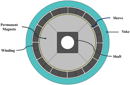
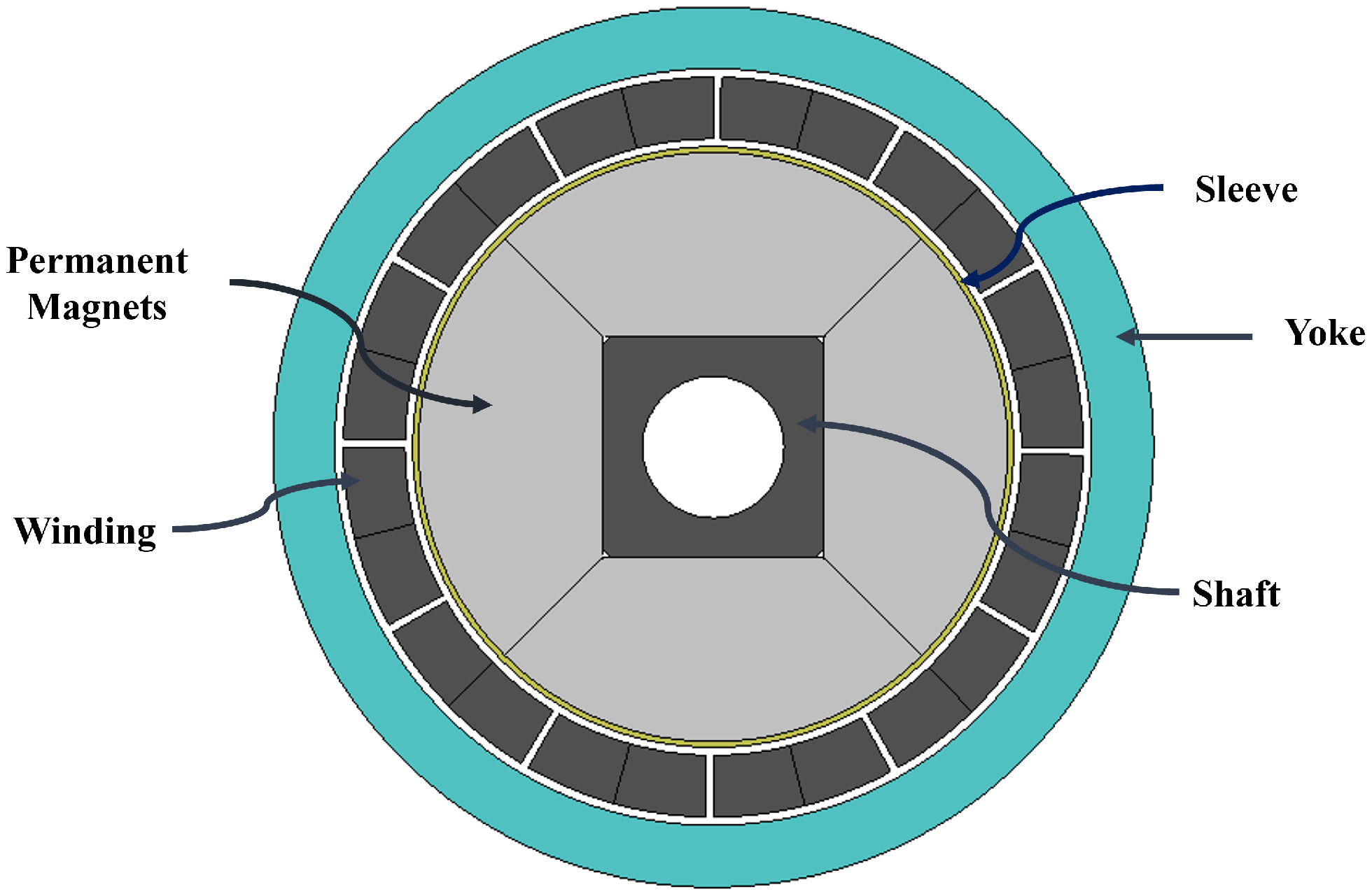
A slotless PMSM motor, shown in Figure 1, was chosen as the benchmark system due to its compact design, precision performance characteristics, and the availability of comprehensive datasheet specifications. The motor was initially designed in JMAG Designer, in which the geometrical structure, material properties, and winding configurations were thoroughly specified. Special care was taken to reflect the important design parameters (stator and rotor size, air-gap length, and magnetic material characteristics) accurately so as to be consistent with the physical machine. The detailed machine design parameters are listed in Table 2.
Figure 1.
2D view of the implemented PMSM.
Table 2.
Design parameters of the Faulhaber 3242G024BX4 PMSM.
Following the design stage, detailed electromagnetic analysis was carried out within JMAG to evaluate the motor’s performance characteristics. The simulations were aimed at deriving important parameters such as the back electromotive force (EMF), torque generation, flux distribution, and current density. These values were compared systematically with the values given in the motor datasheet to confirm the accuracy of the developed model. Any discrepancies that were observed were reduced by refining the model iteratively, such as by refining the geometry and by changing the winding configurations. This validation procedure guaranteed that the simulated motor was very similar to the real-world behavior of the chosen reference machine.
After achieving satisfactory agreement with the datasheet, the validated electromagnetic model was used to generate a reduced-order yet high-fidelity representation using JMAG-RT. The spatial harmonic model (SHM) approach was used to model the nonlinearities and harmonic effects inherent in the motor. The SHM-based representation, in contrast to traditional simplified models, maintains significant phenomena, including magnetic saturation, slotting effects, and nonlinear flux–current relationships. This allows the model to capture the dynamic and nonlinear behavior of the motor in different operating conditions with computational efficiency.
This JMAG-RT model was then integrated into the drive simulation environment, which is the plant that will be further analyzed. This integration enables the motor to be tested under realistic operating conditions, such as transient responses and nonlinear interactions with the drive system. The simulation environment offers a sound platform to experiment with advanced control strategies with high-fidelity electromagnetic properties. After creating and testing the machine model, we then turned to the creation of the drive system, where conventional control approaches were compared to the proposed TD3-based control policy.
2.2. Drive System and Control Strategy
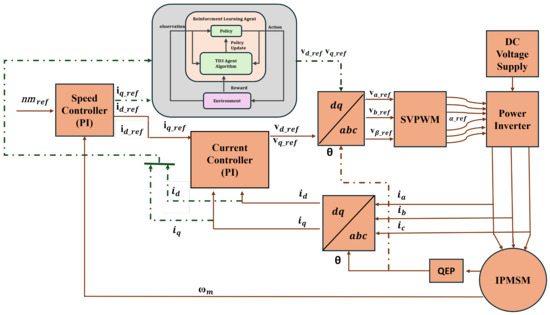
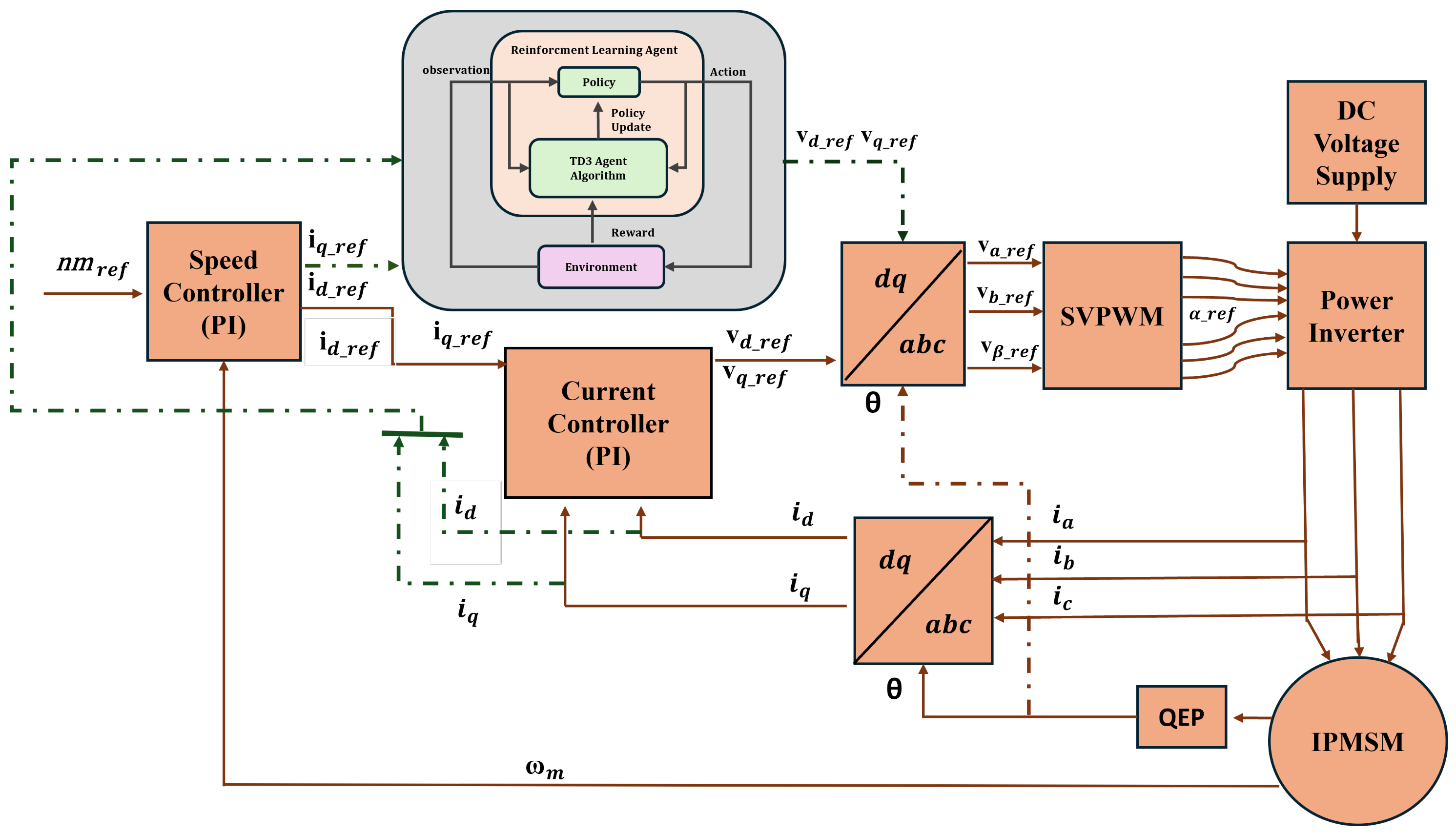
After the high-fidelity motor model was developed, the process of designing and implementing the drive system and the control strategies was undertaken. The drive system is designed in such a way that it allows a thorough comparison of both traditional and innovative control methods under the same operating conditions. A FOC framework, illustrated in Figure 2, is used as the control framework in this work because it is commonly used in high-performance motor drives, and it allows the separation of torque and flux components to enable fine control.
Figure 2.
Block diagram of the FOC incorporating PI and TD3-based current controller.
In the FOC scheme, the d-axis and q-axis currents are controlled with standard PI controllers. The PI-based controller is designed using traditional tuning techniques to obtain a stable and fast dynamic response at nominal operating conditions. This controller is used as a performance benchmark. The control system consists of coordinate transformations, current regulation loops, and space vector pulse-width modulation (SVPWM) to switch inverters on and off to create a complete closed-loop drive system. A simple linear motor model is first used to test the PI controller to determine the baseline performance characteristics, including tracking accuracy, transient response, and steady-state error.
To address the limitations of the conventional PI control in the presence of nonlinearities and variations in the parameters, a control approach grounded in reinforcement learning is suggested, and it is grounded on the TD3 algorithm. Figure 2 illustrates the TD3 controller, which replaces the conventional current regulation loops in the FOC model and which is trained to find the optimal control policies by interacting directly with the motor model. The algorithm employs actor–critic networks, delayed policy updates, and target-policy smoothing to enhance stability and minimize overestimation bias in training. The TD3 agent is trained in the simulation environment with the high-fidelity motor model, which enables it to learn nonlinear dynamics, saturation effects, and harmonic effects not adequately learned by the linear controllers.
To provide a holistic evaluation, comparative analysis was carried out in various situations. The PI-based FOC controller and the TD3-based controller were tested on two motor models, a standard linear model and the high-fidelity nonlinear model created with JMAG-RT. This two-model assessment system enables exploration of robustness and flexibility of controllers. The performance measures include the accuracy of current tracking, torque response, dynamic stability, and sensitivity to nonlinear effects. Specifically, the comparison shows the deterioration of PI controller performance under nonlinear conditions and that the TD3-based approach can sustain high-quality control performance by successfully learning and adapting to system nonlinearities.
3. Electromagnetic Performance Evaluation
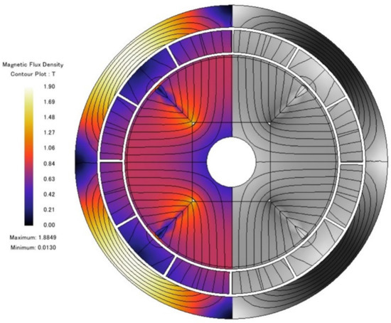
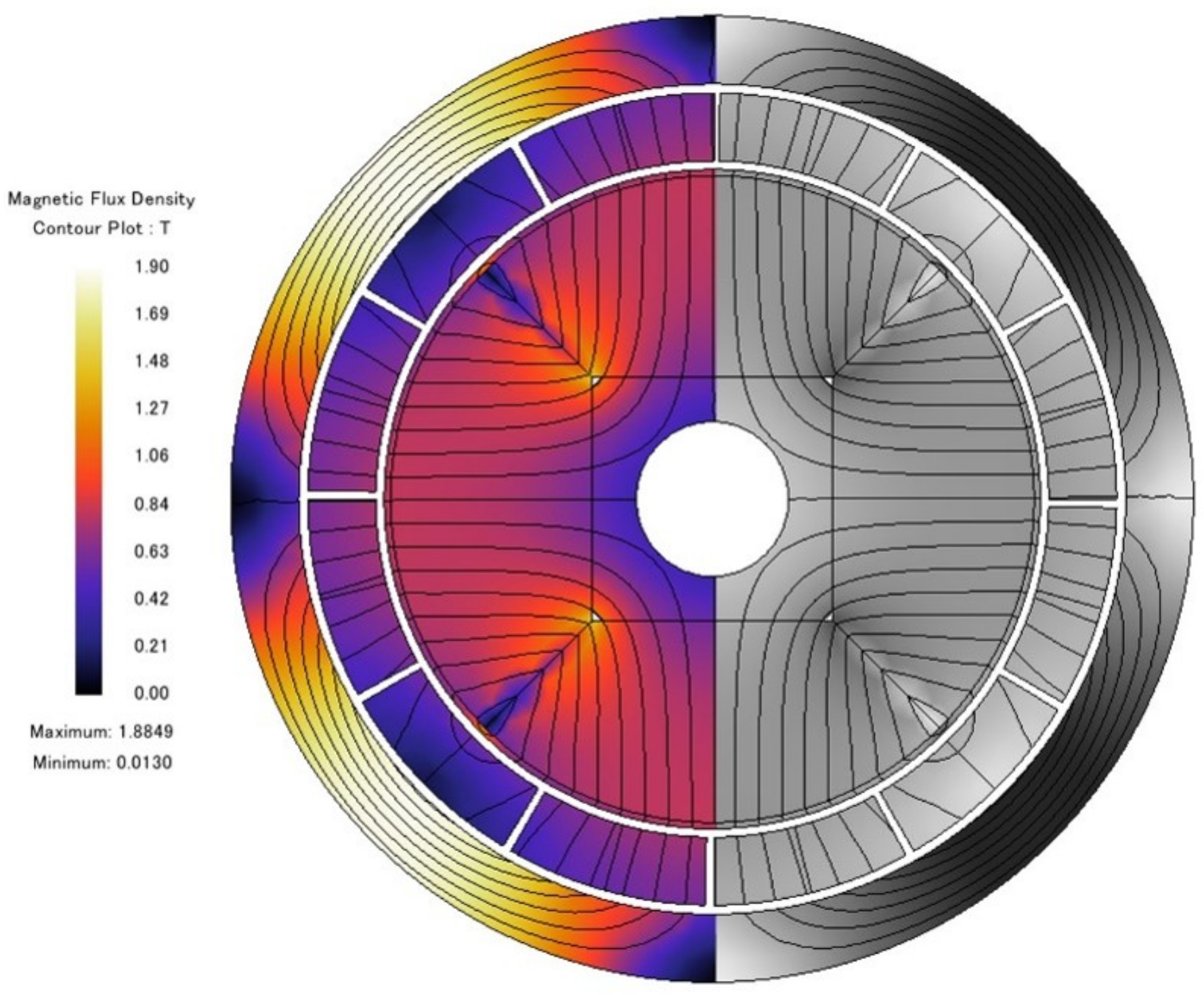
In this section, the electromagnetic performance of the reference motor under no-load and load conditions is validated using FEM in JMAG. The contour plots are used to analyze the initial magnetic field distribution, as depicted in Figure 3. The flux distribution is smooth and continuous throughout the air gap and stator areas, with no severe distortion or localized saturation. The homogeneity of the flux shows accurate electromagnetic design and modeling of the machine.
Figure 3.
Contour plot of magnetic flux density.
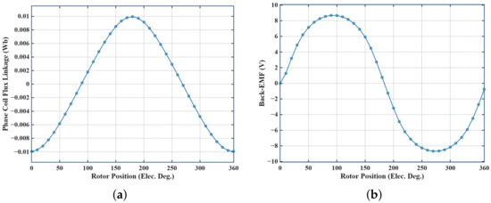
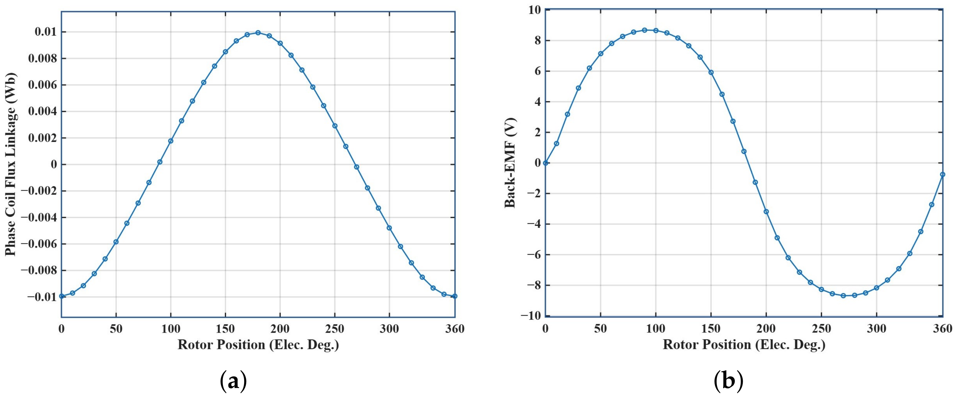
Similarly, the coil flux linkage and back electromotive force (EMF) was measured under no-load conditions. Figure 4a illustrates that the flux linkage waveform has a near-sinusoidal profile with a peak of about 0.01 Wb, which means that there is low harmonic distortion, resulting in a consistent variation of the air gap in the magnetic field with rotor position. Likewise, the back EMF waveform, shown in Figure 4b, is also sinusoidal with a maximum of about 8.68 V, indicating a consistent variation of the air gap in the magnetic field with rotor position.
Figure 4.
Electromagnetic performance as a function of rotor electrical position. (a) Coil flux linkage. (b) Back EMF.
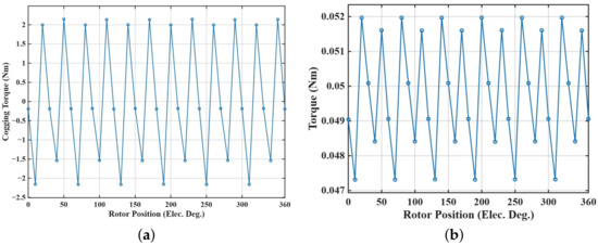
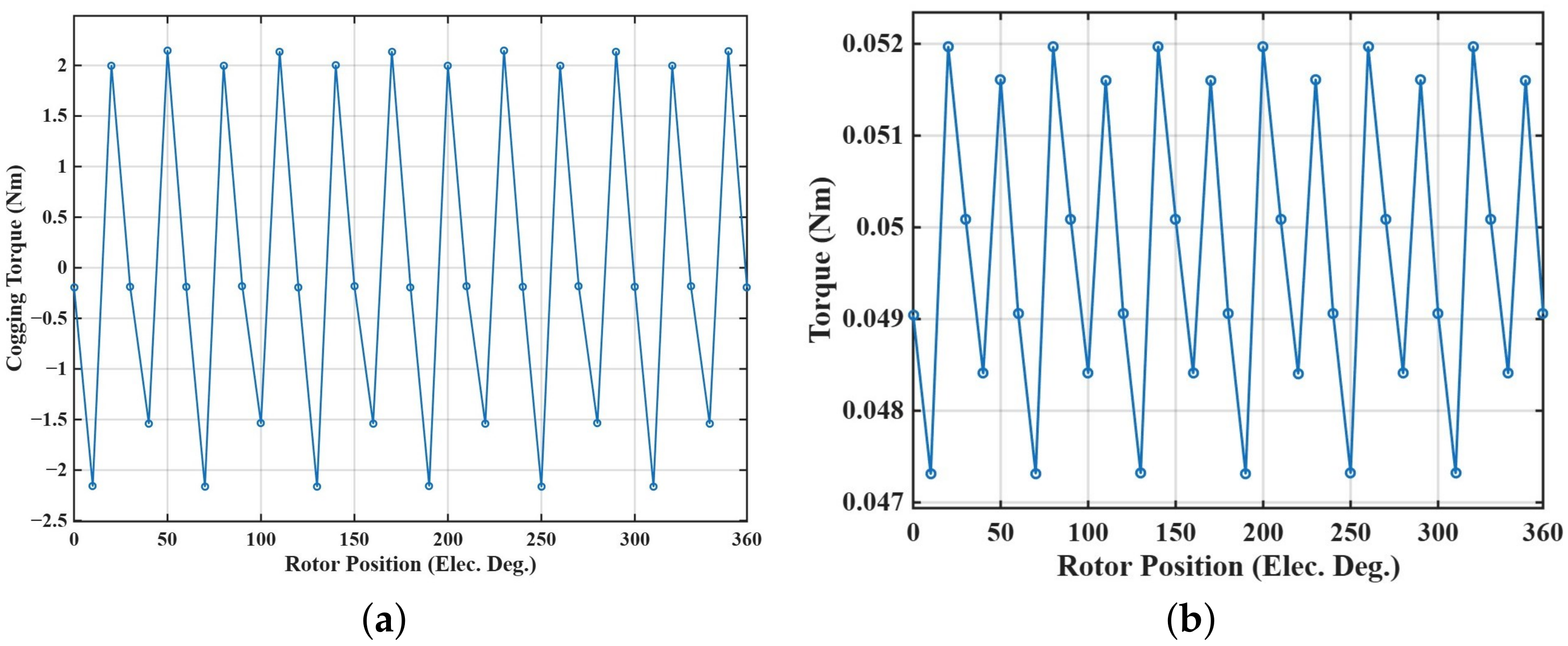
Further, the cogging torque, as illustrated in Figure 5a, was also examined and was found to have a peak about 0.0021 Nm, which represents the torque generated by magnetic interaction depending on the rotor position. Similarly, the electromagnetic torque, as demonstrated in Figure 5b, was analyzed under load conditions, and demonstrates an average of about 0.0497 Nm, matching the machine datasheet. Overall, the results obtained agree with the reference machine’s electromagnetic characteristics; thus, the developed model can be used for further high-fidelity drive modeling.
Figure 5.
Electromagnetic performance as a function of rotor electrical position. (a) Cogging torque (b) Instantaneous torque.
4. Drive Model Development Using JMAG-RT
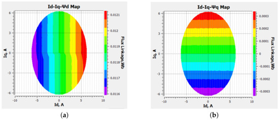
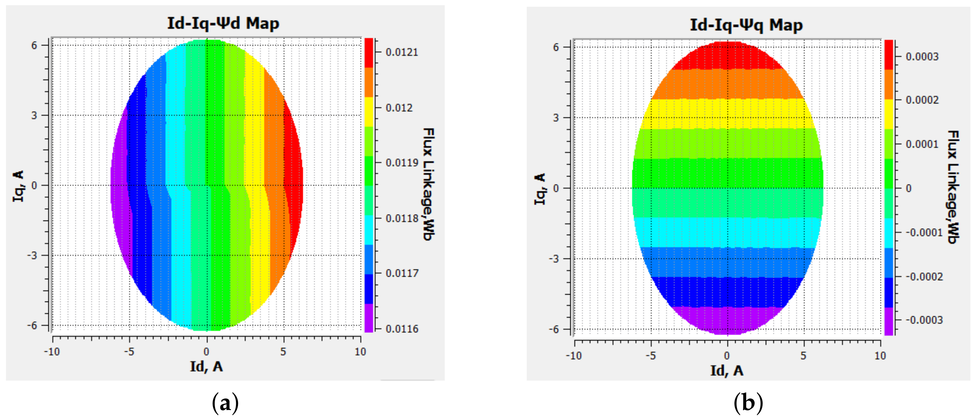
The nonlinear characteristics of the motor are captured using JMAG-RT and represented through flux maps in the d-q axis current plane. The d-axis flux linkage, (d) as illustrated in Figure 6a, is more sensitive to the d-axis current () than to changes in the q-axis current (), shown through the clear change in contour levels along the direction, but is relatively insensitive to changes in . The almost parallel bands of contours on the axis indicate that there is little cross-coupling effect on d, which proves that is the most important component that controls d. In contrast, Figure 6b shows that the q-axis flux linkage (q) varies strongly with . The effect of on q is comparatively weak, indicating limited coupling in this direction. Additionally, the symmetry observed along the positive and negative axis reflects the directional nature of q-axis excitation, with flux magnitude reducing near zero current. Overall, the plots confirm that d is primarily governed by and q by , with only minor cross-coupling effects, particularly at higher current magnitudes.
Figure 6.
Contour map as a function of d-q axis currents. (a) d-axis flux linkage. (b) q-axis flux linkage.
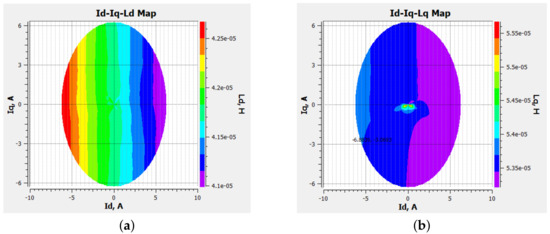
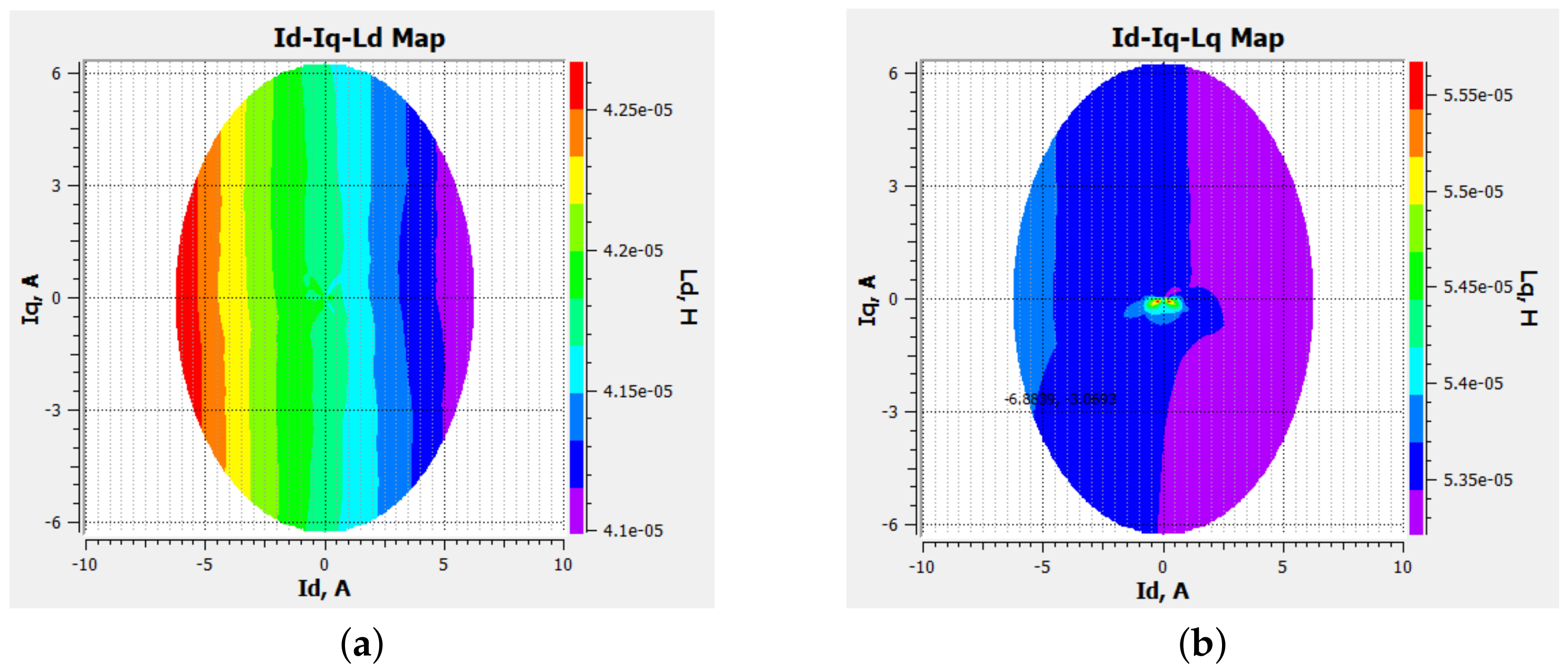
Similarly, as shown in the inductance maps in Figure 7a,b, the d-axis inductance varies noticeably with , as indicated by the gradient change along the d-axis, reflecting the effect of magnetic saturation on the flux–current relationship. The variation along the axis is comparatively minimal, suggesting limited cross-coupling influence on . In contrast, the q-axis inductance () remains nearly uniform over the entire – plane, with only negligible variation, indicating weak sensitivity to both current components. This behavior implies that picks up nonlinear saturation effects along the d-axis, whereas can be assumed to be constant throughout the operating range, which is indicative of a near non-salient characteristic with small nonlinear variations.
Figure 7.
Contour map as a function of d-q axis currents. (a) d-axis inductance. (b) q-axis inductance.
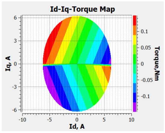
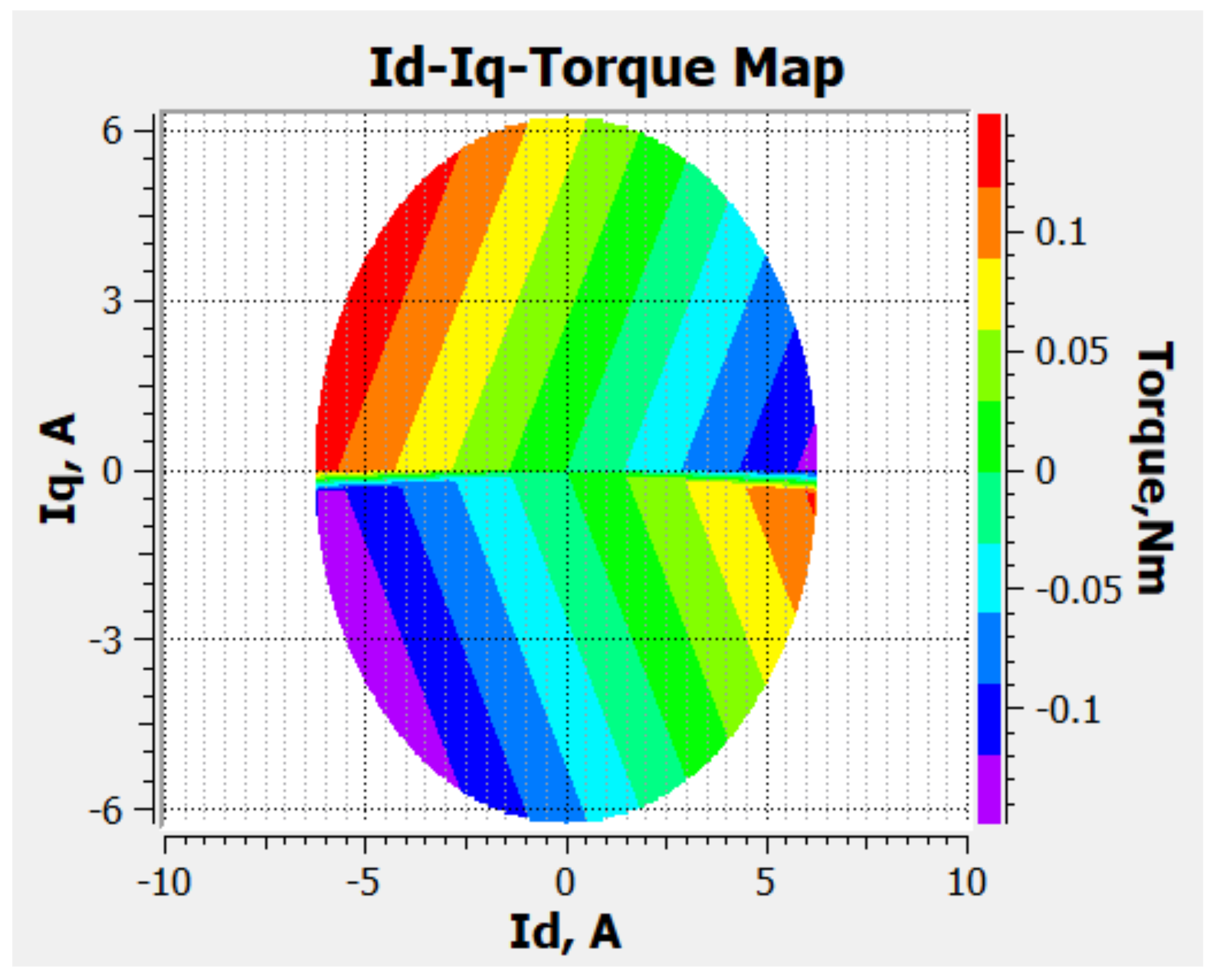
Additionally, the electromagnetic torque map, as illustrated in Figure 8, is nonlinear throughout the – current plane, and it is evidently dependent on both current components. The contour distribution shows that the magnitude of torque rises with , but is modulated by , indicating the effect of the torque-generating and flux-regulating components. We find positive torque in one half-plane and negative torque in the other, showing the directional dependence of . The gradient change between the map is smooth, indicating that the torque varies smoothly, and the contour lines are slightly curved, which implies the presence of nonlinear magnetic effects. This action underscores the fact that the best torque generation is achieved at a given ratio of and , which supports the fact that nonlinear mapping is essential in control implementation.
Figure 8.
Electromagnetic torque contour map as a function of d-q axis currents.
Electromagnetic properties, such as flux linkages, torque, and inductances, are brought into the simulation environment as LUTs. This LUT-based implementation allows the nonlinear motor behavior to be accurately represented in Simulink, creating a high-fidelity plant model to evaluate control.
4.1. PI-Controlled PMSM Drive
A PI-based FOC controller with fixed motor parameters is used to initially assess the performance of the drive system. The d–q-axis current controller gains were determined using the MathWorks Motor Control Blockset function, which uses the modulus optimum (MO) tuning method for the current loop and the symmetrical optimum (SO) tuning method for the speed loop, using motor plant parameters along with the controller sampling times. The current-loop sampling time is ms, corresponding to a 5 kHz PWM frequency, with and . The outer speed PI controller has a sampling time of ms, and the gains are set as and = 0.03035. The corresponding continuous-time integral gains are and . The per-unit normalization specified for the drive model is used for the controllers.
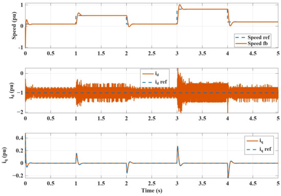
The findings are illustrated in Figure 9, where the speed reference and measured speed are indicated together with the and current responses. The reference speed is applied per-unit (pu), with step changes at t = 1 s, 2 s, 3 s, and 4 s. The measured speed follows the reference with a stable response and negligible steady-state error. Following the step change to 0.5 pu at t = 1 s, the speed attains the maximum overshoot of 0.62 pu at t = 1.052 s and settles down to the reference at t = 1.20 s, corresponding to a settling time of 200 ms. Similarly, the speed exhibits a larger transient overshoot after the step increase to 0.8 pu at t = 3 s. The speed takes 0.062 s to reach 1.0 pu before settling to the desired reference value at t = 3.2 s, corresponding to the same settling time of 200 ms. Despite the increased overshoot at higher operating speeds, the controller maintains stable operation with rapid convergence and satisfactory reference tracking throughout the speed profile. Additionally, the current is kept constant at its reference value of zero, and the current is kept constant at its reference profile, which produces the required torque throughout the speed profile.
Figure 9.
Speed and current tracking performance of the linear PMSM model using PI-based current controller.
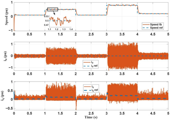
When the nonlinear high-fidelity motor model is subjected to the same controller, significant degradation in current regulation performance is observed, as shown in Figure 10. The , which should ideally be near zero, now chatters up to ±0.6 pu and ±1 pu during speed reference transitions of 0.5 pu and 0.8 pu at t = 1 s and t = 3 s, respectively. Likewise, noticeable transient oscillations are observed for the , where the q-axis current reference is about 0.12 pu and 0.22 pu for the 0.5 pu and 0.8 pu speed command, while the actual current has significant fluctuations up to nearly 0.8 pu. These degraded current regulation characteristics also resulted in noticeable chattering throughout the speed profile. For instance, at t = 1 s for a 0.5 pu speed transition, the actual speed oscillates between 0.47 pu and 0.53 pu around the reference. The reason for this current oscillation is attributed mainly to the difference in the fixed-parameter PI current controller and the operating-point-dependent electromagnetic characteristics represented by the JMAG-RT motor model. Despite the relative moderate variations in flux and inductance distributions, and limited cross-coupling, the variations in these parameters change the current-loop dynamics over the operating range, and can cause increased oscillations when using fixed PI gains.
Figure 10.
Speed and current tracking performance of the nonlinear PMSM model using PI-based current controller.
4.2. TD3-Controlled PMSM Drive
To overcome the PI-based FOC shortcoming, the PI current controller is substituted with a TD3-based control strategy. TD3 agent uses a twin critic network, which decreases the overestimation of the action value, and delayed policy updates and target-policy smoothing help make training more stable. It also offers continuous voltage actions for both the d and q-axes, allowing it to be used directly for current-loop control. Nonetheless, unlike the traditional PI control, the TD3 needs to be trained using a complex algorithm and is sensitive to the choice of hyperparameters, exploration conditions, and training data. The learned policy also relies on the operating conditions observed during training, and may display poor performance when subjected to operating conditions it has not seen before, e.g., load disturbances outside of the training distribution. Furthermore, TD3 lacks the simple analytical guarantees of stability, which are found in classic model-based controllers.
The TD3 agent is trained in the developed high-fidelity simulation environment based on the LUT-based nonlinear motor model. The speed reference and feedback, d–q-axis current and current error, and the error integral of the d–q-axis are sent to the agent as eight state variables. The actor reads this state information, and produces two continuous actions from the d- and q-axis voltage command. Two critic networks estimate the action-value function, and TD3’s delayed actor update and target-policy smoothing algorithm increase training stability and minimize overestimation. The TD3 observation and action variables, along with their description, are listed in Table 3. An adaptive policy is hence directly derived from the interaction with the PMSM drive environment, instead of being based on fixed PI gains. The training is conducted across a series of episodes, during which the agent engages with the environment to acquire the best control actions to manage the existing components. The simulations are run on a computer with an Intel 13th Gen Core i7-13700 (2.10 GHz) processor and an NVIDIA GTX 2080 graphics card, which is capable of performing the computations efficiently during training. The simulation time per episode is about 45 min, and the training was repeated 500 times/iterations until convergence was reached.
Table 3.
TD3 observation and action variables.
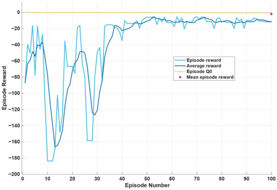
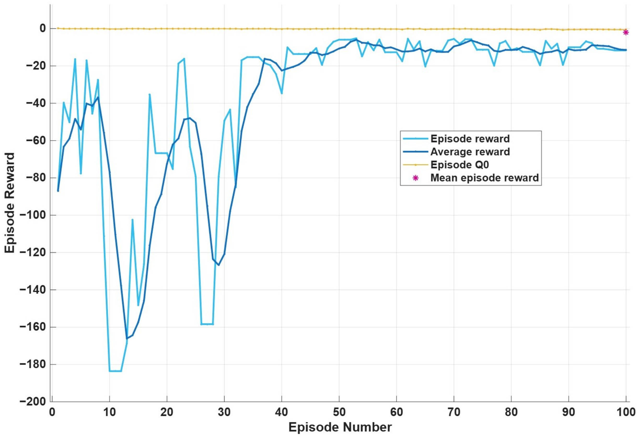
Standard training measures are used to monitor the learning performance, such as cumulative reward and policy stability. The reward, as illustrated in Figure 11, grows with the number of training iterations, which means that the control policy is learned effectively. There is also a decrease in reward variations, which indicates that it converges to a stable solution. The TD3 framework uses exploration noise, delayed policy updates, and twin critic networks to enhance the learning stability and reduce overestimation bias. The significant hyperparameters of the TD3 agent are listed in Table 4.
Figure 11.
Training outcome of the FOC-based TD3 agent current controller.
Table 4.
Key hyperparameters of the TD3 current controller.
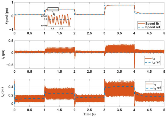
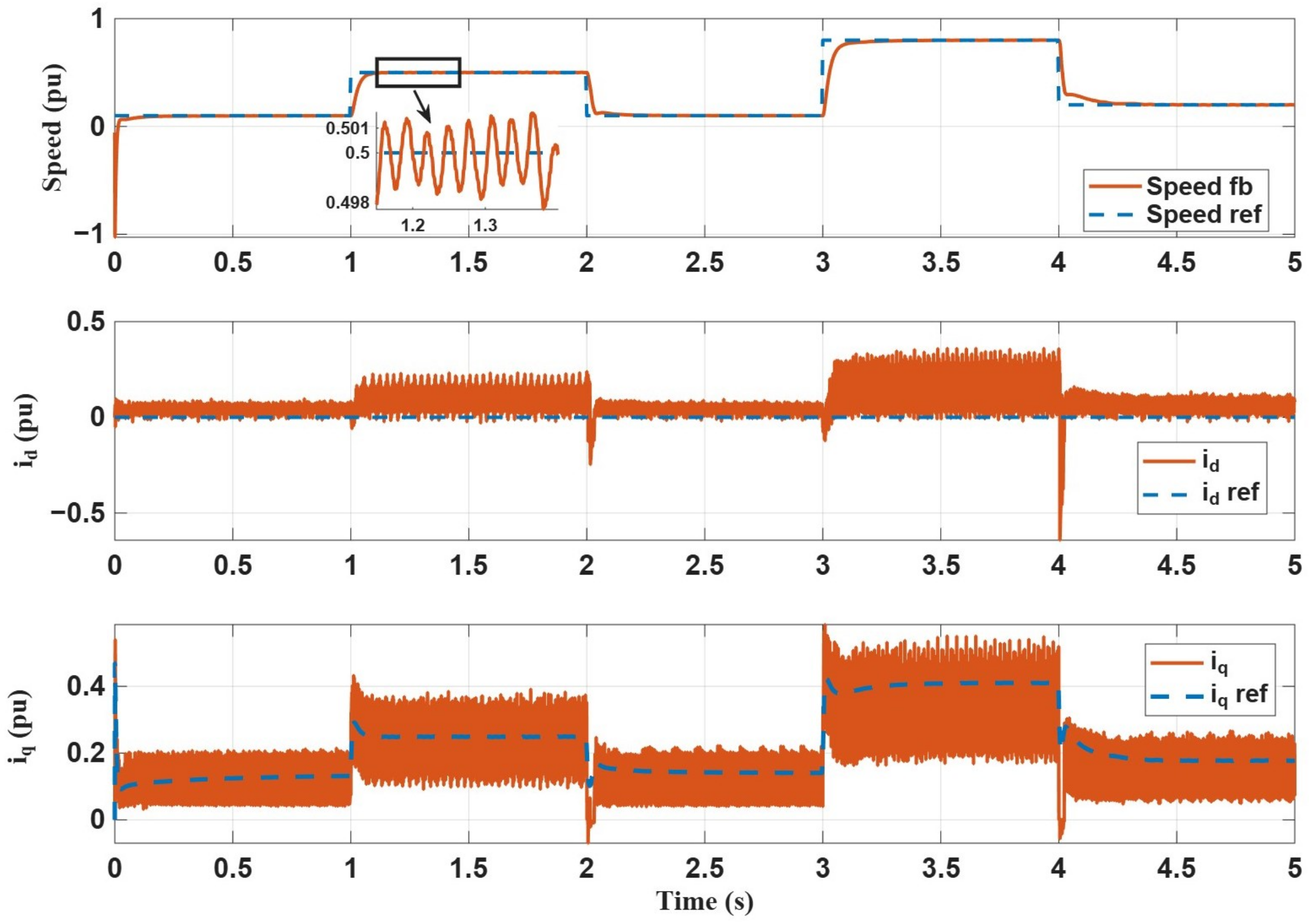
After training, the TD3 controller is implemented in the testing setting with the same reference speed profile as used in the PI-based case. The findings indicate that the TD3-based current controller is much more effective in nonlinear settings, where it can track the d–q axis currents more effectively by surpassing the current transients. As illustrated in Figure 12, unlike the PI-based current controller, the , which was previously chattering around ±0.6 pu and ±1 pu during speed reference transitions at t = 1 s and t = 3 s, is more stable with lower peaks but possesses an average steady-state error of about 0.021 pu. Similarly, the current now effectively follows the reference trajectory with minor oscillations around the reference values. Likewise, the speed response also shows significant improvement: for 0.5 pu at t = 1 s, it shows oscillations of about 0.498 pu to 0.501 pu, with no overshoot or undershoot compared to the PI-based controller.
Figure 12.
Speed and current tracking performance of the nonlinear PMSM model using the TD3-based current controller.
The integral absolute error (IAE) for the three frameworks—the lumped-parameter motor with PI controller, the full nonlinear motor with PI controller, and the nonlinear motor with a reinforcement learning agent (TD3)—are summarized in Table 5.
Table 5.
Comparative IAE performance across control strategies.
The TD3 agent is able to act on the full nonlinear plant to achieve an IAE of 0.008880 rad, which is 17.6% faster than the nonlinear PI value of 0.010772 rad and close to the idealized lumped benchmark of 0.008694 rad. Furthermore, the q-axis current IAE of the TD3-controlled nonlinear PMSM is marginally reduced from 0.270162 to 0.269025 A·s. This small difference suggests that the integral tracking performance is similar, and that the TD3 controller is able to maintain effective q-axis current tracking during the speed transients. On the contrary, for the d-axis current results, the lumped PI has ideal decoupling of 0.001031 A·s, but both nonlinear controllers have very poor performance. The d-axis current for the nonlinear PI controller, shown in Figure 10, exhibits significantly larger positive and negative deviations from the reference value and has a more oscillatory response, while the TD3-based controller response, shown in Figure 12, has a more bounded response with mostly unipolar excursions and smaller peak excursions at the reference value. However, the d-axis current response of the TD3 agent has a systematic, non-zero-mean bias, settling to an approximately 0.024 pu offset during the time interval of 1–2 s and increasing to approximately 0.035 pu after 3.0 s. Due to this, the TD3 controller’s d-axis IAE value of 0.422122 A·s exceeds the nonlinear PI IAE value of 0.312692 A·s, which demonstrates that the overall d-axis tracking deviation is still higher in the TD3 response although the peaks in the oscillations are reduced. The steady-state offset is persistent due to the fact that the TD3 agent does not use integral action explicitly to remove steady-state error, unlike the PI controller. The PI controller’s integral term continuously integrates the residual error until it is reduced to zero, while the TD3 policy learns a direct state-to-action mapping that is optimized while training which does not have a built-in constraint for performing exact zero-error regulation. Thus, the agent settles at a new, less stringent operating point with a small amount of residual d-axis error, but better system performance.
It should be noted that the TD3 agent was trained and tested under the above no-load operating condition. Thus, the present study does not consider load-disturbance conditions outside the training distribution, since they would mainly evaluate the extrapolation ability of the trained policy. Future work will consider evaluating the TD3 controller over a representative set of load torques to further explore the generalization and disturbance-rejection properties of the controller.
5. Conclusions
This paper proposed a PMSM drive current controller based on high-fidelity reinforcement learning, which was based on a FOC framework and involved the replacement of conventional PI current controllers with the TD3 algorithm. A validated JMAG finite element model of the motor was first created, and then nonlinear flux, torque, and inductance maps were generated from the finite element model using JMAG-RT. These were then used as LUTs in MATLAB/Simulink to accurately represent the nonlinear characteristics of the motor.
Comparative results were obtained under both linear and nonlinear motor models, and it was found that the PI controller was satisfactory in the linear motor parameter case but the performance was severely affected when nonlinear effects were introduced, leading to an incremental increase in the speed IAE by 23.9% and by more than twice of the d-axis IAE magnitude increment, reflecting its ability to reject nonlinear cross-coupling. However, by proposing a current controller using a TD3 control method, the current regulation performance of the nonlinear PMSM drive was significantly improved. Compared to the nonlinear-based PI controller, the TD3 agent managed to reduce the speed IAE by 17.6% and obtain an IAE within 2.1% of the idealized lumped-parameter benchmark, while the q-axis current IAE improved marginally by only 0.4%. This came at the expense of d-axis regulation, with the IAE increasing by around 35%, despite the reduced peak-to-peak oscillatory behaviour of the TD3 response. This indicates that reduced ripple does not necessarily translate into lower accumulated tracking error, highlighting d-axis tracking as an area for further improvement. Overall, the results confirm that the TD3 controller improves the speed and q-axis current tracking performance for nonlinear dynamics of the PMSM but worsens the d-axis IAE due to a steady-state bias.
Future work involves expanding the considered performance evaluation of the TD3 controller to a more representative load torque range and comparing its performance with more advanced nonlinear control techniques, such as nonlinear-compensation PI, feedforward-decoupled PI, and sliding mode control (SMC), as well as experimental testing of the physical PMSM drive to test its generalization, disturbance-rejection, and practical implementation capabilities under nonlinear operating conditions.
Author Contributions
K.R. conducted the simulation and wrote the original draft. F.K. and D.Y.U. provided strategic oversight, technical supervision, and led the investigation, validation, and conceptual development of the study. M.S. performed manuscript refinement, visualization, and resource acquisition. All authors have read and agreed to the published version of the manuscript.
Funding
This work was supported by a National Research Foundation of Korea (NRF) grant funded by the Korean government (MSIT) (RS-2026-25489729), and an IITP (Institute of Information & Coummunications Technology Planning & Evaluation)-ICAN (ICT Challenge and Advanced Network of HRD) (IITP-2026-RS-2026-25549459, 10%) grant funded by the Korean government (Ministry of Science and ICT).
Data Availability Statement
All data supporting this study’s findings are included in the article. No additional datasets were generated or used. Further details can be requested from the corresponding authors.
Conflicts of Interest
The authors declare no conflicts of interest.
References
- Rafaq, M.S.; Midgley, W.; Steffen, T. A Review of the State of the Art of Torque Ripple Minimization Techniques for Permanent Magnet Synchronous Motors. IEEE Trans. Ind. Inform. 2024, 20, 1019–1031. [Google Scholar] [CrossRef] [Scilit]
- Chau, K.-T.; Li, W.; Lee, C.H.T. Challenges and Opportunities of Electric Machines for Renewable Energy. Prog. Electromagn. Res. B 2012, 42, 45–74. [Google Scholar] [CrossRef] [Scilit]
- Zhu, Z.Q.; Howe, D. Electrical Machines and Drives for Electric, Hybrid, and Fuel Cell Vehicles. Proc. IEEE 2007, 95, 746–765. [Google Scholar] [CrossRef] [Scilit]
- Rafique, K.; Khan, F.; Majid, A.; Sajid, M. Design and Optimization of a Concentrated Wound Double Tied Arch Bridge Type High Speed IPMSM. In Proceedings of the 2026 1st International Conference on Innovations in Information and Communication Technologies (IICT), Jamshoro, Pakistan, 15–17 January 2026; IEEE: New York, NY, USA, 2026; pp. 1–5. [Google Scholar] [CrossRef] [Scilit]
- Yusivar, F.; Hidayat, N.; Gunawan, R.; Halim, A. Implementation of Field Oriented Control for Permanent Magnet Synchronous Motor. In Proceedings of the 2014 International Conference on Electrical Engineering and Computer Science (ICEECS); IEEE: New York, NY, USA, 2014; pp. 359–362. [Google Scholar] [CrossRef] [Scilit]
- Guo, X.; Wang, W.; Song, S. Design of Permanent Magnet Submersible Motor Driving System Based on FOC Algorithm. In Proceedings of the 2023 26th International Conference on Electrical Machines and Systems (ICEMS); IEEE: New York, NY, USA, 2023; pp. 4943–4946. [Google Scholar] [CrossRef] [Scilit]
- Jahns, T.M.; Kliman, G.B.; Neumann, T.W. Interior Permanent-Magnet Synchronous Motors for Adjustable-Speed Drives. IEEE Trans. Ind. Appl. 1986, IA-22, 738–747. [Google Scholar] [CrossRef] [Scilit]
- Elsherbiny, H.; Szamel, L.; Ahmed, M.K.; Elwany, M.A. High Accuracy Modeling of Permanent Magnet Synchronous Motors Using Finite Element Analysis. Mathematics 2022, 10, 3880. [Google Scholar] [CrossRef] [Scilit]
- Pizzuto, M.; Balamurali, A.; Mohammadi, H.; Kar, N.C. Impact of Model Fidelity on Control and Performance Analysis of Interior Permanent Magnet Synchronous Machines. In Proceedings of the 2024 International Conference on Electrical Machines (ICEM); IEEE: New York, NY, USA, 2024; pp. 1–6. [Google Scholar] [CrossRef] [Scilit]
- Nicola, M.; Nicola, C.-I.; Selișteanu, D. Improvement of PMSM Sensorless Control Based on Synergetic and Sliding Mode Controllers Using a Reinforcement Learning Deep Deterministic Policy Gradient Agent. Energies 2022, 15, 2208. [Google Scholar] [CrossRef] [Scilit]
- Bouguenna, I.F.; Tahour, A.; Kennel, R.; Abdelrahem, M. Multiple-Vector Model Predictive Control with Fuzzy Logic for PMSM Electric Drive Systems. Energies 2021, 14, 1727. [Google Scholar] [CrossRef] [Scilit]
- Vanamala, S.C.; Danduprolu, K.K. Speed Control of PMSM Drive Using Model Predictive Control Based Field Oriented Control. ITEGAM–J. Eng. Technol. Ind. Appl. 2025, 11, 52. [Google Scholar] [CrossRef] [Scilit]
- Bendjedia, B.; Baadj, L.; Ibrahimibrahimi, A. Sliding Mode Control of PMSM Drive for Lightweight Electric Vehicles. In Proceedings of the 2022 19th International Multi-Conference on Systems, Signals & Devices (SSD); IEEE: New York, NY, USA, 2022; pp. 2109–2114. [Google Scholar] [CrossRef] [Scilit]
- Zhang, D.; Sun, M.; Lin, X.; Huang, H.; Zhang, Q. Real-Time Parameter Identification for Model Predictive Control of PMSM Using Incremental LSTM. In Proceedings of the 2025 7th Asia Energy and Electrical Engineering Symposium (AEEES); IEEE: New York, NY, USA, 2025; pp. 371–376. [Google Scholar] [CrossRef] [Scilit]
- Abu-Ali, M.; Berkel, F.; Manderla, M.; Reimann, S.; Kennel, R.; Abdelrahem, M. Deep Learning-Based Long-Horizon MPC: Robust, High Performing, and Computationally Efficient Control for PMSM Drives. IEEE Trans. Power Electron. 2022, 37, 12486–12501. [Google Scholar] [CrossRef] [Scilit]
- Tom, A.M.; Daya, J.L.F. Design of Machine Learning-Based Controllers for Speed Control of PMSM Drive. Sci. Rep. 2025, 15, 17826. [Google Scholar] [CrossRef] [Scilit]
- Nicola, M.; Nicola, C.-I.; Selișteanu, D.; Șendrescu, D. Rapid Control Prototyping of Sensorless Control System for PMSM Based on Multi-Agent Reinforcement Learning and Fractional Order Sliding Mode Control. Eng. Sci. Technol. Int. J. 2025, 66, 102054. [Google Scholar] [CrossRef] [Scilit]
- Dietz, A.; Caruso, M.; Tommaso, A.O.D.; Miceli, R.; Nevoloso, C. Enhanced Mathematical Modelling of Interior Permanent Magnet Synchronous Machine Considering Saturation, Cross-Coupling and Spatial Harmonics Effects. In Proceedings of the 2020 Fifteenth International Conference on Ecological Vehicles and Renewable Energies (EVER); IEEE: New York, NY, USA, 2020; pp. 1–9. [Google Scholar] [CrossRef] [Scilit]
- Nicola, M.; Nicola, C.-I. Improvement of PMSM Control Using Reinforcement Learning Deep Deterministic Policy Gradient Agent. In Proceedings of the 2021 21st International Symposium on Power Electronics (Ee); IEEE: New York, NY, USA, 2021; pp. 1–6. [Google Scholar] [CrossRef] [Scilit]
- Nicola, M.; Nicola, C.-I.; Ionete, C.; Șendrescu, D.; Roman, M. Improved Performance for PMSM Sensorless Control Based on Robust-Type Controller, ESO-Type Observer, Multiple Neural Networks, and RL-TD3 Agent. Sensors 2023, 23, 5799. [Google Scholar] [CrossRef] [Scilit]
- Paponpen, K.; Atipasaworn, T. Improvement Performance of FOC for PMSM Based on Reinforcement Learning TD3 Agent Current Controller. In Proceedings of the 2024 27th International Conference on Electrical Machines and Systems (ICEMS); IEEE: New York, NY, USA, 2024; pp. 2942–2948. [Google Scholar] [CrossRef] [Scilit]
- Mynar, Z.; Vesely, L.; Vaclavek, P. PMSM Model Predictive Control with Field-Weakening Implementation. IEEE Trans. Ind. Electron. 2016, 63, 5156–5166. [Google Scholar] [CrossRef] [Scilit]
- Yadav, K.; Vekanuru, S.; Krishnan, N.V. Deep Learning Observer for Position Estimation in Field-Oriented Control of Permanent Magnet Synchronous Motors (PMSM). In Proceedings of the 2025 11th International Conference on Control, Automation and Robotics (ICCAR); IEEE: New York, NY, USA, 2025; pp. 416–425. [Google Scholar] [CrossRef] [Scilit]
- Rafique, K.; Khan, F.; Majid, A.; Sajid, M.; Milyani, A.H. Design, Optimization, and Indirect Field-Oriented Control of a Concentrated Wound DAB-type High Speed IPMSM. IEEE Access 2026, 14, 111357–111369. [Google Scholar] [CrossRef] [Scilit]
- Wang, M. A Novel Mathematical Nonlinear PMSM Realization Method for Electric Machine Emulator. IEEE J. Emerg. Sel. Top. Power Electron. 2022, 10, 4171–4181. [Google Scholar] [CrossRef] [Scilit]
- Li, X.; Song, W. Research on Control Strategy of PMSM for Electric Vehicles Based on Nonlinear Model. In Proceedings of the 2022 IEEE 5th Advanced Information Management, Communicates, Electronic and Automation Control Conference (IMCEC); IEEE: New York, NY, USA, 2022; pp. 170–174. [Google Scholar] [CrossRef] [Scilit]
- Rafique, K.; Majid, A.; Khan, F.; Khalil, S.A. Electromagnetic Performance Evaluation and Indirect Field-Oriented Control of a Spoke-Type Inverted V-Shape Asymmetric Interior Permanent Magnet Synchronous Machine. In Proceedings of the 2026 5th International Conference on Computing, Mathematics and Engineering Technologies (iCoMET), Sukkur, Pakistan, 22–23 May 2026; IEEE: New York, NY, USA, 2026; pp. 1–6. [Google Scholar] [CrossRef] [Scilit]

Disclaimer/Publisher’s Note: The statements, opinions and data contained in all publications are solely those of the individual author(s) and contributor(s) and not of MDPI and/or the editor(s). MDPI and/or the editor(s) disclaim responsibility for any injury to people or property resulting from any ideas, methods, instructions or products referred to in the content. |
© 2026 by the authors. Licensee MDPI, Basel, Switzerland. This article is an open access article distributed under the terms and conditions of the Creative Commons Attribution (CC BY) license.