


Abstract
Lane Keeping Assistance (LKA) systems play a critical role in enhancing vehicular safety and driving comfort by maintaining lane alignment and mitigating risks associated with driver distraction or drowsiness. These systems rely on sensor data to execute corrective steering or braking actions, yet their dependence on interconnected electronic components exposes them to a range of safety and cybersecurity threats. Attackers can exploit vulnerabilities in sensors, communication protocols, and Electronic Control Units (ECUs), potentially triggering false interventions or disabling safety functions. This paper presents a comparative Threat Analysis and Risk Assessment (TARA) of two LKA system architectures using the Medini Analyze tool. The first architecture employs a hierarchical controller with driver-intention detection and Electronic Stability Control (ESC)-based actuation. The second architecture employs a Learning-Based Model Predictive Control (LBMPC) framework enabling situation-adaptive decision-making. Through systematic identification and evaluation of threats and vulnerabilities, the analysis assesses risk levels associated with each design. The comparative analysis reveals trade-offs among architectural complexity, system robustness, and exposure to potential vulnerabilities, offering practical insights to improve the safety and security of LKA system designs.
Keywords:
automotive security; threat; risk mitigation; LKA; ECU; TARA; functional safety; ISO 11270:2014 1. Introduction
LKA is a key function of Advanced Driver Assistance Systems (ADAS) designed to prevent unintentional lane departures by monitoring a vehicle’s lateral position using sensors such as cameras, radar, or LiDAR and applying corrective steering inputs when necessary [1]. While LKA improves driving safety and comfort, its performance can be compromised by adverse environmental conditions, degraded road markings, sensor malfunctions, or software-related faults, and its direct influence on steering makes it inherently safety-critical [2]. The growing reliance on interconnected Electronic Control Units and vehicle networks also exposes LKA to potential security threats, amplifying the need for systematic risk evaluation. Threat Analysis and Risk Assessment (TARA) offers a structured methodology for identifying, assessing, and prioritizing threats to both safety and security, aligning with standards such as ISO 26262 [3] and ISO 21448 [4]. Applied to LKA, TARA facilitates early detection of vulnerabilities in perception, control, and communication subsystems, enabling targeted mitigation strategies that enhance functional reliability in increasingly connected and autonomous vehicle environments [5]. Furthermore, consumer adoption has increased significantly: as of late 2024, 87% of drivers keep lane-departure warning or prevention systems activated—a sharp increase from 51% several years earlier. These insights collectively highlight the considerable safety potential of LKA, while also emphasizing gaps between theoretical impact and practical outcomes, making systematic risk assessment methodologies like TARA essential for realizing and ensuring its effectiveness.
Even with these advances, important challenges remain. Robust lane detection remains difficult when markings are worn, repainted during road works, or partially occluded by snow or heavy rain. Interpreting driver intent is another sensitive point: if the system misreads a deliberate maneuver as a drift, it can intervene at the wrong moment. And at the actuation level, sudden lane changes, merges, or obstacle avoidance demand control strategies that are both adaptive and dependable. Urban traffic magnifies these issues. Frequent lane changes, intersections, and unpredictable road users complicate perception and control [6,7,8]. Adverse weather can degrade sensor performance, increasing uncertainty. To maintain credibility, LKA must also minimize false alarms and avoid corrective actions that feel unnecessary or annoying. Together, these factors argue for ongoing innovation, careful validation, and broad testing across realistic scenarios.
1.1. TARA-Threat Analysis and Risk Assessment
TARA is an essential tool for analyzing threats, evaluating their likelihood and impact, and prioritizing mitigation strategies. Incorporating TARA ensures that cybersecurity measures are precise and effective. In this way, the vehicle’s most critical vulnerabilities are addressed, and the overall resilience of its systems is improved. STRIDE (Spoofing, Tampering, Repudiation, Information Disclosure, Denial-of-Service, and Elevation of Privilege) [9] is a threat modeling framework introduced by Microsoft that classifies security threats into six categories based on attacker objectives and known system vulnerabilities. The approach relies on graphical classification rather than quantitative risk metrics. Although originally developed for the Information Technology (IT) domain, STRIDE has gained relevance in the automotive sector following its endorsement by SAE J3061 [10]. It is now frequently applied in various automotive Threat Analysis and Risk Assessments.
Cyberattacks are evolving at an exponential rate, directly impacting the automotive sector. Vehicle-to-everything (V2X) functions and advanced driver assistance systems (ADAS) in modern vehicles are among the primary targets of these cyberattacks. These incidents can be addressed by implementing measures throughout the vehicle’s lifecycle. Some regulations, such as R155 from the United Nations Economic Commission for Europe (UNECE), emphasize implementing measures throughout the vehicle lifecycle. In this context, combining lifecycle governance with semi-automated cybersecurity testing, along with concepts such as Cybersecurity Assurance Levels (CAL) and Targeted Attack Feasibility (TAF), allows for a more structured, efficient, and comprehensive assessment of risks in automotive systems.
1.2. Motivation and Contributions
The motivation is to strengthen the evidence base around the security and reliability of LKA, guiding safer, more resilient designs. By putting two representative architectures side by side, this study offers concrete takeaways for researchers, engineers, and policymakers working on next-generation LKA.
The main contributions of this paper are as follows:
- A comparative security evaluation demonstrating how the transition from deterministic, hierarchical control to predictive, data-driven algorithms (LBMPC) fundamentally shifts the system attack surface from localized physical tampering to network-level data integrity and availability.
- An evaluation of LBMPC for adaptive decision-making, highlighting continuous improvement and real-time responsiveness.
- An assessment of a hierarchical controller with driver-intention detection and ESC actuation.
- Threat, vulnerability, and mitigation identification for each architecture, with targeted recommendations to harden system resilience.
- Practical insights to inform LKA designs that improve safety, reliability, and user acceptance-supporting the broader goal of reducing traffic injuries and fatalities.
The remaining sections of this paper are organized as follows: Section 2 provides an overview of related work; Section 3 describes the proposed research methodology; Section 4 presents the architecture analysis; Section 5 shows the results; and Section 6 presents the conclusion with future research directions.
2. Related Work
Hema et al. [11] combined a Deep Belief Network (DBN) and an Enhanced LSTM model optimized with Improved Grey Wolf Optimization (IGWO). It outperformed existing methods in predicting vehicle trajectories and lane changes. Yang et al. [12] proposed an improved dynamic occupancy grid probabilistic model (DGPM) for lane changing assistance in autonomous vehicles, introduced a Markov model for predicting vehicle behavior, and established a cost-based decision strategy to enhance safety and drivability during lane changes. Wang et al. [13] introduced a novel LKA system based on a nonlinear driver-vehicle–road (DVR) model, demonstrating its differential flatness and integrating Model-Free Control to compensate for modeling errors, thereby validating its enhanced lane-keeping performance and reduced driver workload compared to linear robust LKA systems. Mehmet et al. [14] performed a TARA on the over-the-air (OTA) update process of the LKA module. They identified 37 threats, 35 damage scenarios, and determined 8 cybersecurity goals with 20 countermeasures. The proposed approach effectively evaluates cybersecurity risks and provides measures to mitigate vulnerabilities in ADAS systems. Wang et al. [15] developed a systematic cyber-physical vulnerability assessment for the Lane-Keeping Control (LKC) system of autonomous vehicles. They proposed novel index-based evaluation metrics and conducted Hardware-in-the-Loop (HiL) experiments to measure the impact of cyber-attacks on safety, performance, and vehicle stability. The study provides guidelines for attack detection, diagnosis, and countermeasures, enhancing the security and resilience of LKC systems. Ghosh et al. [16] proposed an integrated threat analysis approach for autonomous vehicle perception systems that combines mission-centric TARA, STPA-Sec, and STRIDE modeling. They introduced the AI Relevance Factor (RF) and object-relevancy metrics to dynamically assess cyber-physical risks in AV operating-design domains. The study provides a foundation for security-by-design and guides future experiments on vision-based AV perception systems. Jayaratne et al. [17] developed a novel simulation-based framework for systemic TARA of connected vehicles, extending ISO/SAE 21434 to evaluate cyberattacks at the transport network level. The framework was demonstrated through case studies of remote attacks on vehicle infotainment systems, quantifying operational impacts and highlighting factors such as traffic density and network configuration that contribute to systemic risk. This approach enables a comprehensive assessment of cyber–physical threats, supporting the design of robust cybersecurity strategies for connected vehicle systems.
Security Standards and Regulations
ISO 11270:2014 provides foundational guidance for LKA, establishing core control strategies, minimum functional requirements, driver interface specifications, diagnostic criteria, and prescribed failure responses [18]. It also defines standardized environmental and test-track conditions to assess system performance, specifically for highway or equivalent road operations, excluding scenarios such as temporary or irregular lane markings like those in construction zones. While ISO 11270:2014 is instrumental in shaping LKA design and evaluation, its emphasis on performance metrics and deterministic failure responses does not account for the dynamic interplay of safety and security risks in connected or autonomous systems as discussed in Table 1. This gap underscores the need for a complementary methodology, such as TARA, that systematically identifies and mitigates both unintentional and adversarial threats across the perception, decision-making, and control layers of LKA, thereby enriching the conventional, performance-centric standards-based approach.
Table 1.
Comparison of key standards/regulations related to Lane Keeping Assistance systems.
3. Research Methodology
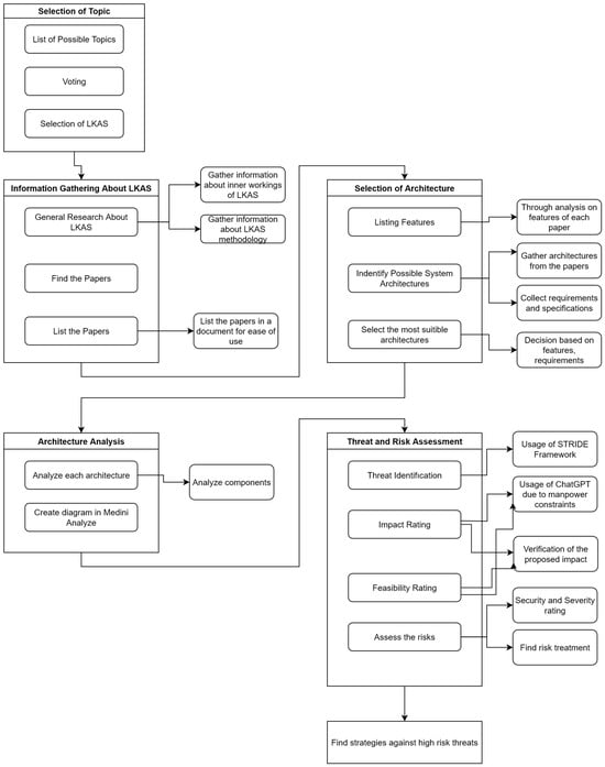
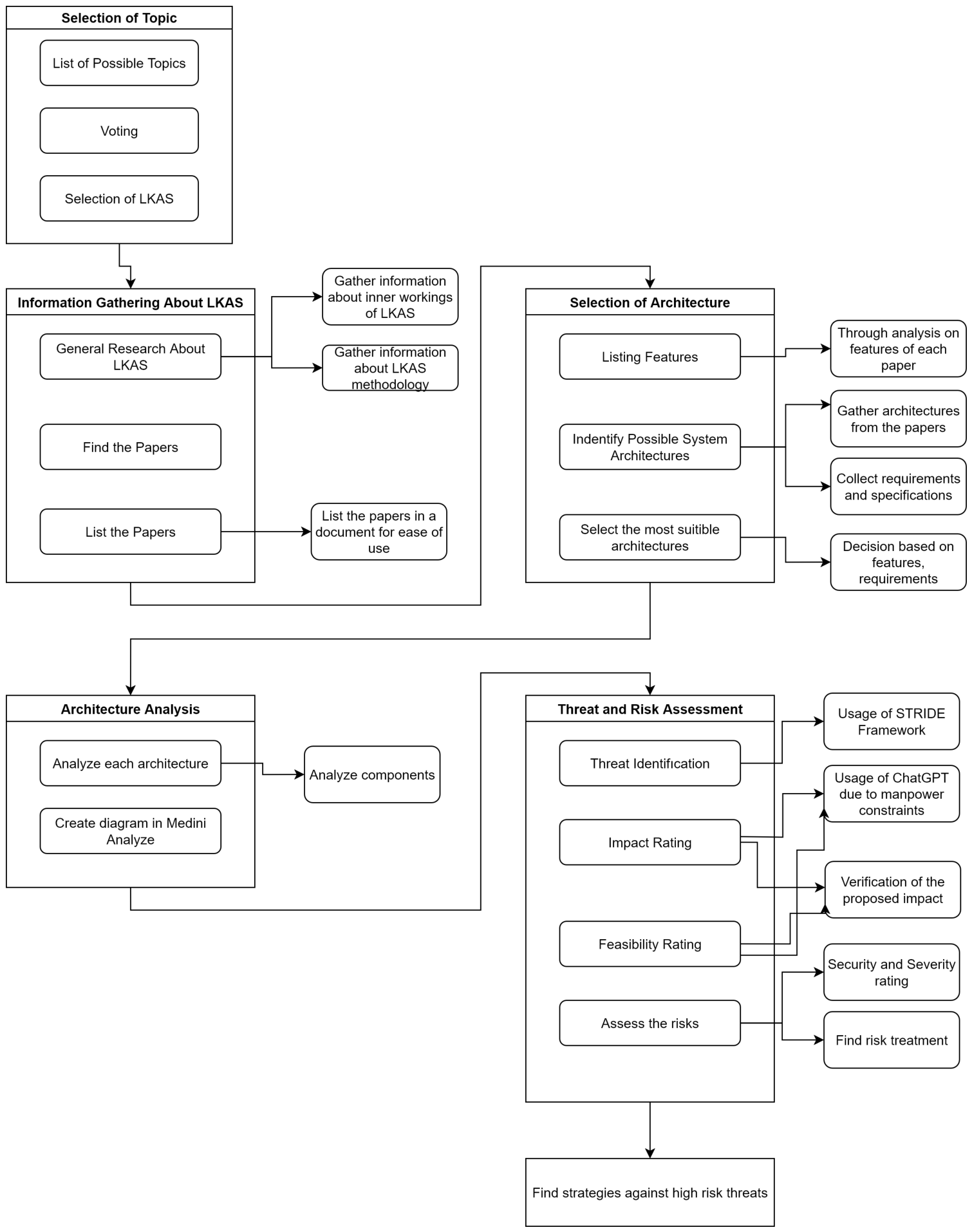
This section presents the methodological framework used to study an LKA system. A precise strategy is developed to enhance the system’s security and safety, ensuring a systematic and thorough analysis of potential threats and vulnerabilities. The structured approach facilitated an extensive investigation into the components and effectiveness of LKA systems, providing a robust foundation for selecting an optimal architecture for analysis. The research methodology comprises several distinct phases aimed at systematically analyzing the LKA system with respect to its architecture, security, and threat assessment as shown in Figure 1.
Figure 1.
Workflow of proposed research methodology.
3.1. Selection of Automotive System
The initial phase of this research involved selecting a specific automotive system for in-depth analysis. A comprehensive list of system features, including ADAS, infotainment, and driver monitoring systems, was compiled and evaluated for its technological innovation and industry relevance. LKA was selected based on its safety-critical nature, widespread deployment in ADAS, and direct influence on vehicle lateral control. The rationale for choosing LKA was its critical safety function and its active role in vehicle lateral control, which involves direct interaction with the steering system. This characteristic makes it a compelling subject for a security analysis, as a compromised LKA system could directly impact vehicle dynamics and safety.
It must be noted that this study executes a preliminary, architectural-level threat assessment rather than a complete production-phase ISO/SAE 21434 TARA. While Medini Analyze automates initial asset identification and generates underlying attack paths based on the defined system boundaries, this work focuses specifically on threat identification and initial risk scoring. Comprehensive damage scenario mapping, Cybersecurity Assurance Level (CAL) derivation, and exhaustive attack path validations are considered implementation-phase activities and fall outside the scope of this comparative architectural analysis.
The Impact Rating is determined by assessing the potential damage to safety, financial standing, operational capability, and privacy. Safety impacts carry the highest weight, particularly scenarios resulting in unintended steering actuation. The Attack Feasibility is quantified based on five parameters: the time required, the attacker’s necessary expertise, knowledge of the system design, the window of opportunity, and the required equipment. A threat is only classified as high-risk if it pairs a severe operational impact with a highly feasible attack path (e.g., remote execution requiring minimal specialized hardware).
To align cybersecurity findings with ISO 26262 functional safety, identified threats are mapped to top-level operational hazards. For an LKA system, the primary hazardous event is unintended or erroneous lateral steering actuation at highway speeds, which carries an Automotive Safety Integrity Level (ASIL) rating of ASIL D. Consequently, cybersecurity threats targeting sensor integrity or control command availability directly compromise the primary safety goal: preventing uncommanded steering interventions.
3.2. Research Questions
Formulating the research questions was a key step in defining the direction of this study and ensuring a focused investigation into the LKA system. This step was intended to align the research objectives with the analytical framework, enabling a structured examination of both functional safety and cybersecurity aspects using TARA. The process began by establishing the overarching objective of this research: to evaluate the resilience of LKA systems against combined safety and security risks, and to identify how TARA can be adapted to address these risks in an integrated manner. This involved reviewing the existing literature on LKA architectures, understanding their core functional elements, and identifying potential vulnerabilities or hazards.
Based on these objectives, the research questions were crafted to focus on the operational components of LKA, the threats that may compromise them, and the degree to which TARA can systematically identify, prioritize, and mitigate these risks. The questions aim to bridge the current gap between safety-only hazard assessments and comprehensive safety–security evaluations.
Accordingly, this study addresses the following key questions:
- RQ1: What are the critical components and interconnections within LKA systems that represent potential safety hazards or cybersecurity attack surfaces?
- RQ2: Which safety–security threats and risks can be identified and prioritized for LKA systems through the application of TARA?
These questions served as the foundation for the subsequent phases of the methodology, from the literature review and architectural analysis to the detailed threat and risk assessment.
3.3. Exclusion and Inclusion Criteria
A systematic literature review was conducted to compile a comprehensive set of research papers on LKA systems. The process began with a general research phase to identify relevant papers on LKA, followed by a list of papers for ease of use. To ensure the relevance and quality of the selected literature, strict inclusion and exclusion criteria were established, following protocols similar to those in established academic frameworks.
The following are the inclusion criteria adopted in our research:
- Studies, technical reports, or standards that address LKA or closely related driver assistance technologies (e.g., Lane Departure Warning, Lane Centering).
- Research addressing functional safety, cybersecurity, or integrated safety–security assessments in the context of automotive systems.
- Methodologies, frameworks, or case studies applying or adapting TARA to automotive domains.
- LKA architectures incorporating perception (e.g., cameras, LiDAR), decision-making modules, and actuation subsystems.
- Peer-reviewed publications from different publishers and databases (IEEE, ACM, Science Direct, Springer, Taylor & Francis), industry guidelines, regulations, or standards published between 2019 and 2025 to capture recent technological and regulatory developments.
The following are the exclusion criteria adopted in our research:
- Studies focused solely on non-automotive applications of lane-keeping or related sensing technologies (e.g., robotics, maritime navigation).
- Research limited to driver behavior studies without technical system-level analysis.
- Methodologies addressing only hazard analysis without cybersecurity considerations.
- Obsolete standards not currently in practice for LKA evaluation.
- Publications without architecture, verifiable data sources, or peer-reviewed validation.
3.4. Selection and Data Extraction
The literature review process commenced with the initial identification of 50 research papers on LKA systems. A thorough review of these research papers identified three distinct architectural models representative of common LKA system designs, sourced from [2,8,23]. This process involved listing the features from each paper and identifying possible system architectures.
Rather than selecting a single system, two specific architectures were chosen for granular threat and risk assessment to represent a fundamental shift in automotive control paradigms. Architecture 1 serves as a baseline for traditional, deterministic hierarchical control, where high-level decision-making and lower-level actuation are strictly isolated. Architecture 2 represents a modern, highly coupled Learning-Based Model Predictive Control (LBMPC) system. This selection enables a comparative analysis of how the transition from isolated, rule-based logic to adaptive, data-driven predictive control alters the vulnerability profile of LKA systems.
This architectural analysis process was crucial for understanding the core components, their interconnections, and the data flows within the systems, culminating in the creation of threat modeling diagrams in Medini Analyze [24].
3.5. Features Comparison
Table 2 shows the comparison of different features in Lane Keeping Assistance. To classify the papers according to their features, the most suitable features for this work were first selected. Then, the papers were searched for keywords related to the topics, such that a paper was considered suitable if the keyword was found alongside relevant information about the corresponding feature.
Table 2.
Comparison of features in Lane Keeping Assistance.
4. Architecture Analysis
In accordance with TARA methodology, this section defines the Target of Evaluation (TOE) by establishing the system boundaries, data flows, and trust models required for the subsequent threat analysis.
4.1. Architecture-1: LKAS
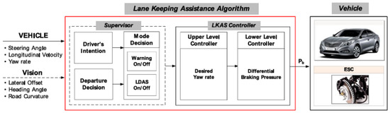
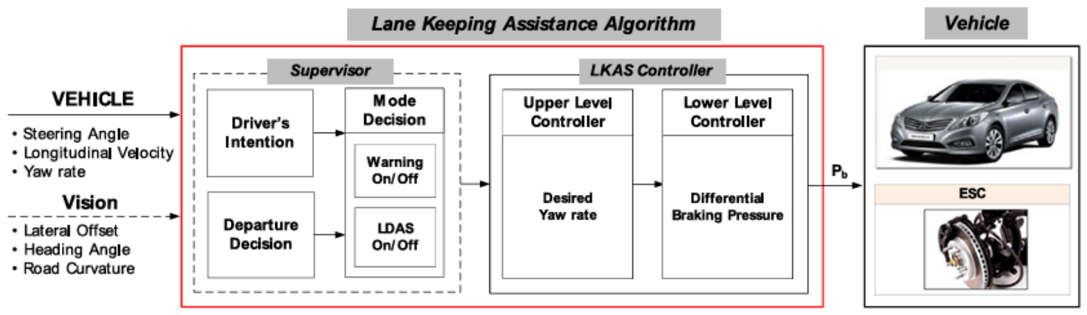
This architecture, presented as a block diagram in Figure 2, illustrates a different approach to a Lane Keeping Assistance (LKA) system [8]. It lays out the system’s logic, showing how different inputs are processed to control the vehicle’s behavior. The operational flow is structured, progressing from data acquisition to processing to command execution. The system begins by gathering information from six inputs. The vehicle inputs—Steering Angle, Longitudinal Velocity, and Yaw Rate—provide data on the car’s current state. Simultaneously, vision inputs—Lateral Offset, Heading Angle, and Road Curvature—describe the vehicle’s position and the road’s geometry. Two main control blocks then process this data. The Supervisor handles high-level decisions. It uses modules such as “Driver’s Intention” and “Departure Decision” to determine the appropriate operational mode for the system. The output of this process determines whether and when the system issues a Warning or activates the LDAS.
Figure 2.
LKAS architecture [8].
The LKAS Controller handles the core control logic. It has two parts: an “Upper Level Controller” and a “Lower Level Controller”. The upper level determines the Desired Yaw rate needed to keep the vehicle in its lane and passes this value to the lower level. The lower level then calculates the Differential Braking Pressure required to achieve that Desired Yaw rate. Finally, the system’s commands are carried out by the ESC (Electronic Stability Control). The Po output from the controller is sent to the ESC, which then applies the necessary braking pressure to individual wheels to steer the car and keep it physically in the lane. This entire process, from data collection to final action, outlines the logic of this particular LKA architecture.
4.1.1. Components
This section details the components of the LKA architecture and outlines their functions within the system.
- Vehicle Inputs: These are the physical sensor readings that provide the system with information about the car’s movement. They include data on the steering angle, the vehicle’s speed (longitudinal velocity), and its rotation rate (yaw rate).
- Vision: This component provides information about the vehicle’s position relative to the road. It provides the system with data on the car’s lateral offset from the lane centerline, its heading angle relative to the lane, and the curvature of the road ahead.
- Supervisor: This is a logical unit that processes the incoming data to make high-level decisions. It includes a module for assessing the “Driver’s Intention” and another for making a “Departure Decision,” which together determine the system’s operational mode. Based on this, it controls whether a warning is enabled and whether the Lane Departure Assistance System (LDAS) is activated.
- LKAS Controller: This block handles the core control logic. It has two parts: an “Upper Level Controller” that calculates the Desired Yaw rate, and a “Lower Level Controller” that then uses it to determine the Differential Braking Pressure needed to achieve that yaw rate.
- ESC: Electronic Stability Control is a vehicle system that enhances stability through braking. It receives a Po signal from the LKAS Controller and performs the necessary braking to keep the vehicle in its lane.
- Vehicle: This represents the physical car itself. It houses the ESC and is the final destination for the system’s commands.
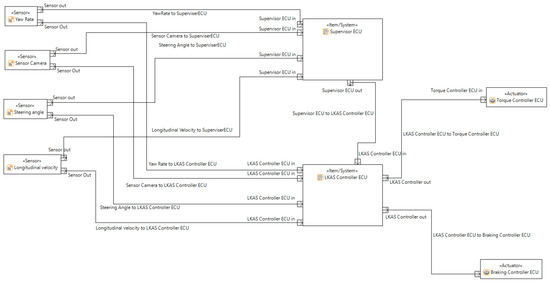
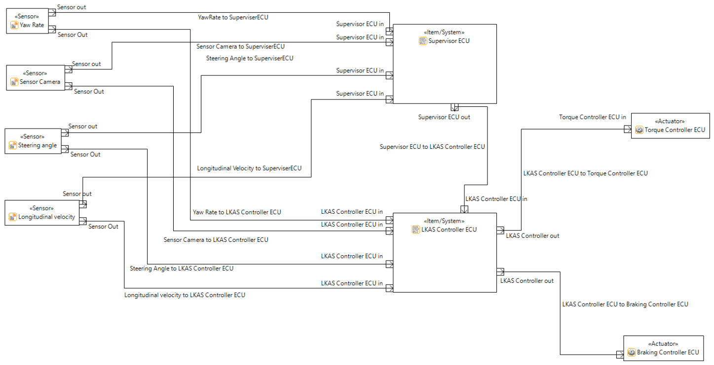
To ensure reproducibility of the threat model in Medini Analyze, specific system boundaries and communication assumptions were defined as shown in Figure 3. Internal communication between the sensor suite, Supervisor ECU, and LKAS Controller ECU is modeled over a standard Controller Area Network (CAN) bus. It is assumed this internal network lacks native payload encryption, representing a standard legacy configuration. The primary external trust boundaries exposed to potential attackers include the physical OBD-II diagnostic port (facilitating unauthorized diagnostic commands or mechanic spoofing) and the vehicle’s Telematics Control Unit (TCU), which serves as the vector for remote Denial of Service (DoS) and illegitimate software update attacks.
Figure 3.
STRIDE threat-modeling diagram, generated using Ansys Medini Analyze of archi-1: LKAS.
4.1.2. Connections
This section describes the connections between the components of the LKA model.
- The Yaw Rate Sensor sends its data to both the Supervisor ECU and the LKAS Controller ECU.
- The Sensor Camera also transmits its data to both the Supervisor ECU and the LKAS Controller ECU.
- The Steering Angle Sensor sends its data on the steering wheel’s position to both the Supervisor ECU and the LKAS Controller ECU.
- The Longitudinal Velocity Sensor sends its speed data directly to the LKAS Controller ECU.
- The Supervisor ECU receives data from the Yaw Rate, Sensor Camera, and Steering Angle sensors. It then sends its processed output to the LKAS Controller ECU.
- The LKAS Controller ECU is the central hub. It receives inputs from all four sensors and the Supervisor ECU. From there, it sends commands to the two actuators: the Torque Controller ECU and the Braking Controller ECU.
- The Torque Controller ECU receives commands from the LKAS Controller ECU to apply torque to the steering wheel.
- The Braking Controller ECU receives commands from the LKAS Controller ECU to manage the vehicle’s braking functions.
4.2. Architecture-2
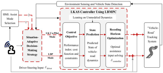
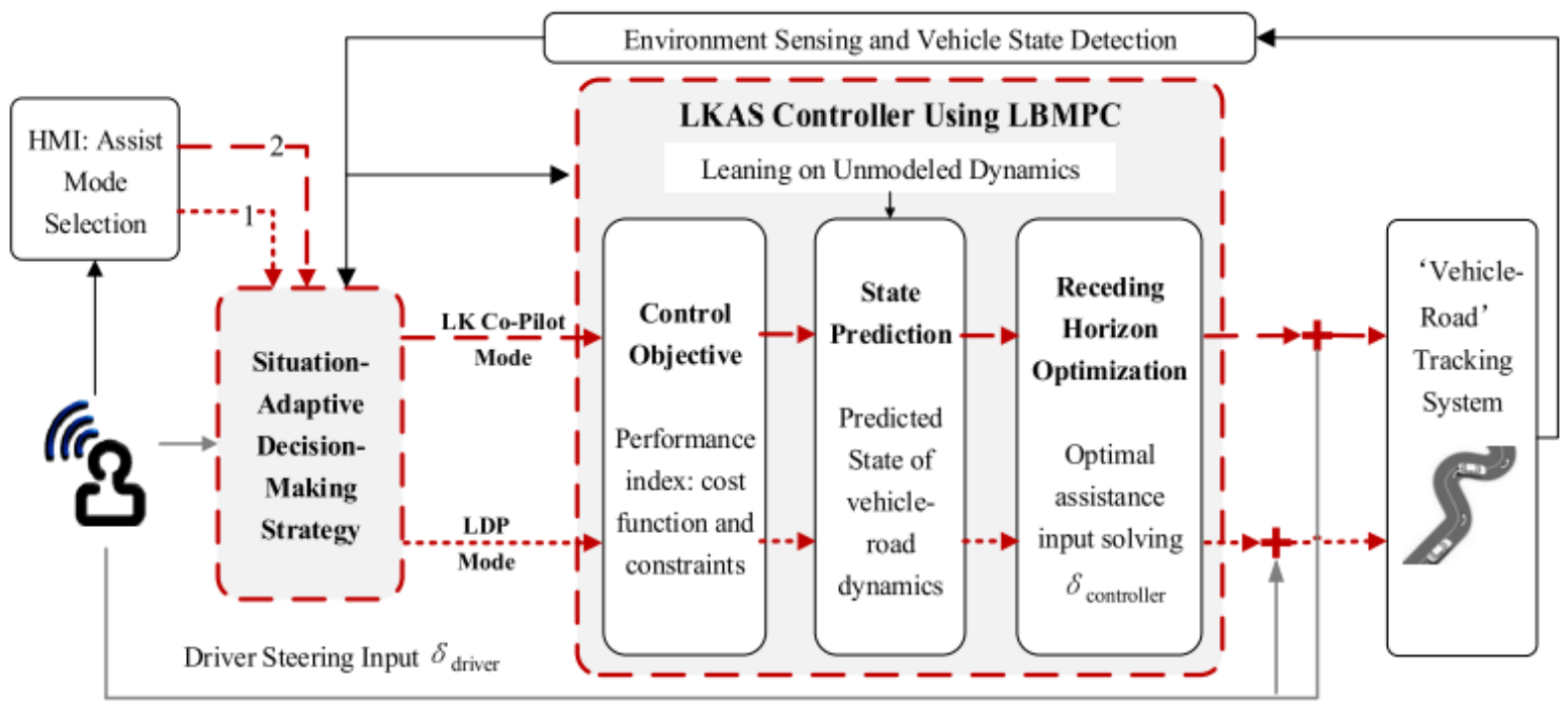
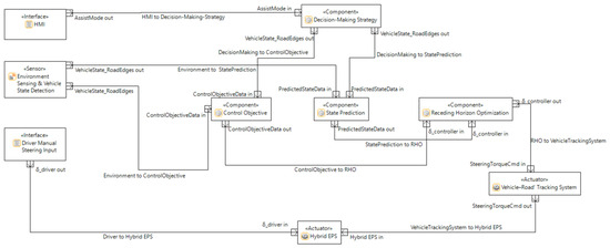
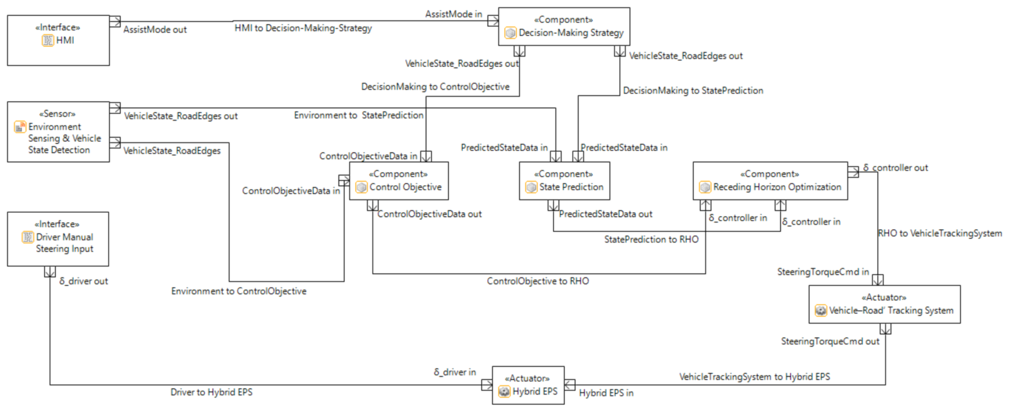
In this section, we describe the major components for the existing LKAS using LBMPC architecture [2], along with their connections as shown in Figure 4. Each module plays a distinct role while exchanging signals with other modules to ensure smooth operation and cooperative control between the system and the driver.
Figure 4.
LKAS using LBMPC architecture [2].
4.2.1. Components and Connections
This architecture is centered on a cooperative control strategy in which a Situation-Adaptive Decision-Making Strategy and an LKAS Controller work together to provide optimal assistance. The system takes into account both environmental information and the driver’s input.
- Environment Sensing and Vehicle State Detection: This component gathers information from onboard sensors to detect road edges, lane boundaries, and vehicle dynamics. The processed outputs are provided to the modules responsible for prediction and for defining the control objective.
- Human–Machine Interface (HMI): The HMI allows the driver to select the assistance mode, such as Lane Departure Prevention (LDP) or Lane-Keeping Co-Pilot (LK Co-Pilot). The selected assist mode is communicated to the Decision-Making Strategy module.
- Situation-Adaptive Decision-Making Strategy: This is the core logic of the system. It integrates vehicle state information and driver preferences to define the control objectives. It also defines the driver’s steering input () and the selected HMI mode to determine the appropriate system behavior.
- LKAS Controller Based on LBMPC: The LKAS Controller is the core decision and control unit of the system. Its sole purpose is to generate the most suitable steering assistance at every moment. For this purpose, it relies on a Learning-Based Model Predictive Control (LBMPC) algorithm. Unlike regular controllers, the LBMPC not only predicts how the vehicle will react over the next few seconds but also learns its model from real-world driving feedback. This learning feature allows the controller to improve its predictions over time and calculate precise, fault-tolerant steering commands in the face of uncertain road or vehicle conditions. It consists of three main sub-modules.
- Control Objective: This component specifies the system’s performance objectives, such as lane-keeping precision. It receives input from the Environment Sensing module and studies the performance index, cost function, and constraints for the optimization problem.
- State Prediction: The state prediction module forecasts the future dynamic response of the vehicle–road system from its present state and the control target.
- Receding Horizon Optimization (RHO): The RHO module calculates the optimal corrective steering input by solving an optimization problem over a finite horizon. This module is the central computation engine of the controller.
- Vehicle–Road Tracking System: This block models the dynamic interaction between the vehicle and the road. It receives the optimized control inputs from the RHO and converts them into implementable steering commands.
4.2.2. Connections
- Environment_to_Situation_Adaptive Decision-Making Strategy: The vehicle state and road edge data are transmitted to the decision-making module.
- Environment_to_LKAS Controller: The vehicle state and road edge data are also fed directly into the LKAS Controller, specifically to the Control Objective and State Prediction sub-modules.
- HMI_to_Situation-Adaptive Decision-Making Strategy: The Assist Mode signals are transmitted to define the level of steering assistance.
- DecisionMaking_to_LKAS Controller: The module sends a signal deciding the operational mode (LK Co-Pilot Mode or LDP Mode) to the LKAS Controller, which enables or disables certain control functions.
- Driver_to_DecisionMaking: The driver’s steering input () is received to analyze the driver’s intent.
- ControlObjective_to_StatePrediction: Control objective data is provided to enable prediction of future states.
- ControlObjective_to_Receding Horizon Optimization (RHO): Control objective data is sent to the RHO module for constrained optimization.
- StatePrediction_to_RHO: The state prediction information is sent to the RHO for optimization.
- RHO_to_Vehicle–Road Tracking System: The optimal assistance steering input () is transmitted as the steering command.
- Vehicle–Road Tracking System_to_Steering Actuator: The module sends a SteeringTorqueCmd to the vehicle’s steering system.
- RHO_to_Vehicle–Road Tracking System: The is received for execution.
In Figure 5, the LKAS model shows how different modules—sensing, decision-making, prediction, and control—work together as a team. Information from the Environment Sensing and Vehicle State Detection unit is sent to both the Control Objective and State Prediction modules. At the same time, the HMI allows the driver to choose the assist mode, which feeds into the Decision-Making Strategy. All of this information comes together in the Receding Horizon Optimization (RHO), where the best possible steering command () is calculated. The LBMPC controller continuously processes the information received from the Environment Sensing block together with the outputs of the State Prediction and Situation Adaptive Decision-Making modules in order to generate the steering command required for lane keeping. During each control cycle, the prediction process is updated using the latest available vehicle and environmental data, allowing the controller to continuously adjust the steering command according to the current driving conditions. Therefore, the controller operation depends on the integrity and availability of the exchanged information, since compromised or unavailable data may influence both the prediction process and the steering commands applied by the Vehicle–Road Tracking System. This command is then executed by the Vehicle–Road Tracking System and the Hybrid EPS, which smoothly blend it with the driver’s steering input () to keep the car centered in its lane in a balanced, natural way. Similar to the first architecture, the Medini Analyze model for the LBMPC system relies on defined trust boundaries. The continuous data streams between the Environment Sensing modules, Decision-Making Strategy, and the LKAS Controller are modeled over a high-speed CAN-FD (Flexible Data-rate) bus to accommodate the higher bandwidth required by the predictive controller. While the internal bus facilitates rapid data exchange, the lack of native message authentication exposes the system to data manipulation. The external attack surfaces remain the physical OBD-II interface and the OTA (Over-The-Air) update gateway, which are modeled as the primary entry points for elevation of privilege and remote availability (DoS) attacks targeting the controller’s prediction horizon.
Figure 5.
STRIDE threat-modeling diagram, generated using Ansys Medini Analyze of archi-2.
5. Results
To evaluate and compare the two existing architectures, a STRIDE-based threat modeling analysis was conducted using Medini Analyze. To determine the severity levels (Critical, High, Medium, Low, QM) presented in Table 3, the risk assessment process utilized the tool’s built-in framework. Medini deterministically calculates the final threat ratings based on the severity levels assigned to specific operational aspects: potential Impact and Attack Feasibility. Impact was assessed across four dimensions (safety, operational degradation, financial damage, and privacy), with safety hazards weighted highest. Attack Feasibility was scored using five standard parameters (elapsed time, attacker expertise, system knowledge, window of opportunity, and specialized equipment requirements). Based on these inputted parameters, the software algorithmically generates the final severity categorizations, which were overseen and manually verified by the authors to ensure the accuracy of the final security ratings.
Table 3.
STRIDE-based threat comparison between Architecture 1 and 2.
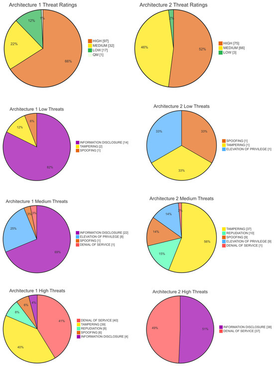
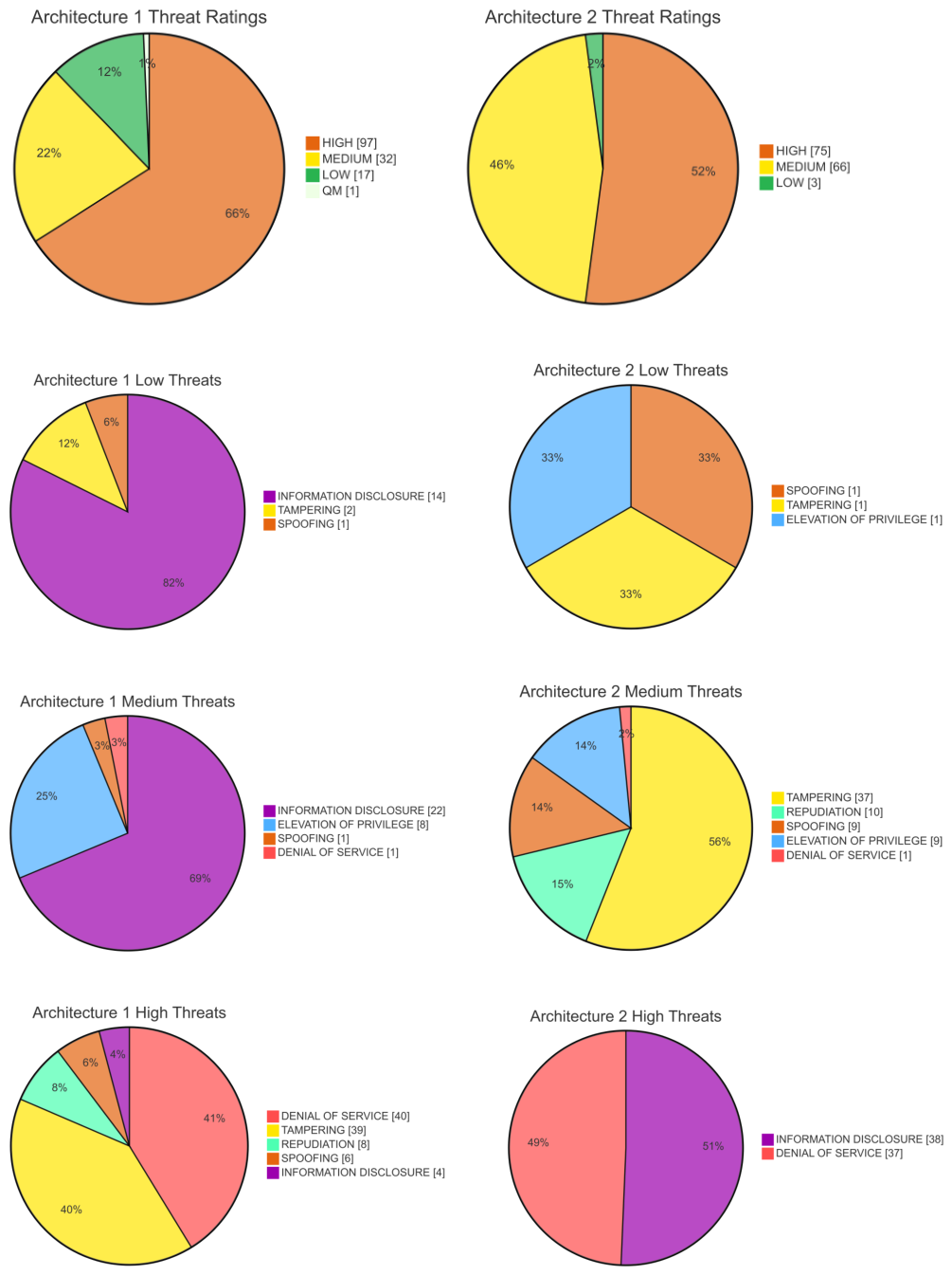
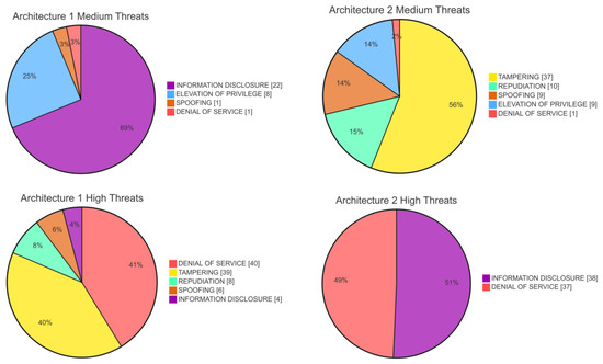
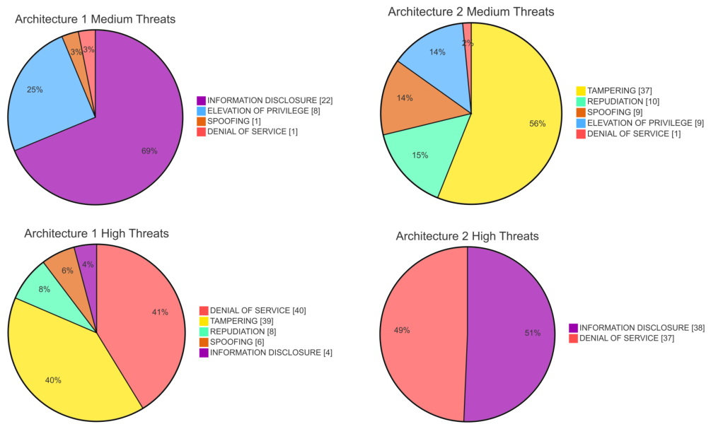
Architecture-1 tends to spread threats across different severities (high, medium, and low), with some Quality Management (QM). The detailed proportional distribution of these low, medium, and high-severity threats is visualized in Figure 6 and Figure 7. This distribution means risks are more manageable and mitigation strategies can be prioritized, while architecture [2] shows a tendency toward concentrated high-severity threats (e.g., Information Disclosure with 38 high threats, DoS with 37 high threats, Elevation of Privilege with 9 medium threats). This makes it riskier, since high-level threats demand urgent remediation. Architecture-2 exhibits a more balanced distribution of threats across severity levels, with fewer high-severity threats than Architecture-1. This suggests that its associated risks may be easier to prioritize and mitigate. However, the overall security posture ultimately depends on the effectiveness of the implemented countermeasures and the impact of individual threats.
Figure 6.
Comparison of threats in threat models between Architecture 1 and Architecture 2.
Figure 7.
Comparison of threats in threat models.
For Architecture 1, the most common vulnerabilities are Tampering (39 of high severity) and Denial of Service (40 also of high severity), followed by Information Disclosure, which spans high (4), medium (22), and low (14) severities. Other categories, such as Spoofing and Repudiation, have even fewer occurrences, mostly also in the high-severity range. Architecture 2 also depicts the aggregation of threats that fall into nearly the same categories but with marked differences. Tampering is dominated by medium-severity threats (37), whereas Denial-of-Service remains a significant high-severity threat (37). In addition, Information Disclosure appears with 38 high-severity cases. Spoofing and Repudiation do exist, but with relatively small numbers, while Elevation of Privilege poses a moderate threat (9 medium, 1 low).
Architecture 1 has 147 threats consisting of 1 QM, 17 low, 32 medium, and 97 high. Architecture 2 has 144 threats consisting of 3 low, 66 medium, and 75 high. Denial of Service threats account for 41% of the high threats in Architecture 1 and 49% in Architecture 2, indicating they require prioritized mitigation. However, lower threat counts do not equate to a more secure system. System security must be evaluated by aggregating operational impact and attack feasibility. Architecture 1 presents vulnerabilities primarily in the Tampering category. These attacks generally require physical access to the internal bus, lowering their feasibility. Architecture 2 concentrates its high-severity risks in Denial of Service and Information Disclosure. Because the LBMPC controller requires continuous sensor data streams, it is highly sensitive to remote availability and data poisoning attacks. The analysis demonstrates that transitioning to predictive control shifts the primary security concern from physical tampering to network data integrity, rather than establishing one architecture as definitively more secure.
To illustrate failure propagation within the highly coupled LBMPC architecture, consider a sustained Denial of Service (DoS) or data tampering attack on the CAN-FD bus connecting the Environment Sensing module to the LKAS Controller. Because the LBMPC relies on continuous environmental feedback, this corrupted information causes immediate functional degradation within the State Prediction module. Consequently, the Receding Horizon Optimization (RHO) is forced to compute the optimal steering assistance using degraded or extrapolated road states. This control abnormality propagates to the Vehicle–Road Tracking System, resulting in automated steering torque that opposes the actual road curvature. Ultimately, this forces the human driver to abruptly override the system via manual steering input to maintain lateral stability, creating a safety hazard.
Mitigation Approach for High and Medium Severity
The TARA methodology generated a series of mitigation strategies to address the identified high- and medium-severity threats. While the raw software output utilizes standard IT terminology, these concepts must be translated into specific automotive hardware and protocol-level implementations to maintain the strict latency and safety constraints required by an LKA system. The mitigation analysis reveals differing defensive requirements based on the underlying architecture.
- Cryptographic authentication and data encryption map to the Secure Onboard Communication (SecOC) protocol for internal buses, supported by Hardware Security Modules (HSMs) integrated into the ECUs. Architecture 1 heavily relies on this defensive layer to prevent sensor spoofing, requiring 44 instances of cryptographic authentication for high-risk threats and 20 instances of data encryption. Architecture 2 requires fewer explicit cryptographic integrations (10 total instances) but still depends on HSMs to manage keys without delaying the steering control loop.
- Network isolation and intrusion detection requirements necessitate deploying an Automotive Intrusion Detection and Prevention System (IDPS) at the central gateway, alongside a Secure Gateway (SGW) to filter traffic from external physical interfaces. Both architectures require IDPS implementations (4 instances in Architecture 1; 3 in Architecture 2) to monitor internal bus traffic for timing anomalies and DoS attempts, as well as strict SGW controls to restrict diagnostic port access.
- Memory and physical tamper protections correspond to Secure Boot implementations and hardware trust anchors on the ECUs to restrict execution to cryptographically signed firmware. Architecture 1 requires these primarily for memory protection against medium-risk threats (six instances). Architecture 2 demands significant physical and logical tamper protections (14 instances) to secure its prediction engine against unauthorized logic modifications.
- Algorithmic resilience is uniquely highlighted in the mitigation data for Architecture 2. The TARA tool identified rate limiting and redundancy (20 instances), along with security controls embedded directly within the Receding Horizon Optimization (6 instances) and State Prediction (6 instances) modules. This indicates that predictive controllers require mitigations integrated directly into the control logic to handle data poisoning, rather than relying solely on network-level perimeter defenses.
Because Architecture 1 and Architecture 2 differ fundamentally in control design and algorithmic complexity, their threat distributions cannot be compared to declare one architecture definitively more secure. Instead, the comparison demonstrates how increased algorithmic coupling shifts the primary attack surface from localized physical tampering to network-level data integrity and availability threats.
6. Conclusions and Future Work
This paper applied a comparative TARA to evaluate two distinct LKAS architectures. While the baseline functional performance and dynamic adaptability of these systems are assumed based on their original design specifications, this study strictly isolates and maps their theoretical cybersecurity risk profiles. By assessing the operational impact and attack feasibility of potential threats, this study mapped the specific risk profile of each system. Both designs satisfy LKA functional requirements, but they present different security trade-offs. The hierarchical architecture is simpler and primarily vulnerable to localized physical hardware tampering. The LBMPC architecture provides superior dynamic control but relies on continuous sensor data pipelines, making it vulnerable to remote DoS and data manipulation. Adopting predictive controllers requires shifting security strategies toward continuous data validation and onboard message authentication. Future work will involve Hardware-in-the-Loop (HiL) testing to measure actual control degradation during simulated communication attacks. Future research should also scale this comparative TARA framework to comprehensive Automated Driving System (ADS) stacks, analyzing cross-module failure propagation across integrated perception, localization, trajectory planning, and safety-monitoring units.
Author Contributions
Conceptualization, A.K.; Methodology, A.K., V.-l.C. and S.G.; Writing—original draft, A.K., V.-l.C. and S.G.; Writing—review & editing, C.E.; Supervision, C.E. and R.K.; Project administration, C.E. and R.K. All authors have read and agreed to the published version of the manuscript.
Funding
This research received no external funding.
Data Availability Statement
No new data were created or analyzed in this study. Data sharing is not applicable to this article.
Conflicts of Interest
The authors declare no conflicts of interest.
References
- Yang, Z.; Shen, C.; Shao, W.; Xing, T.; Hu, R.; Xu, P.; Chai, H.; Xue, R. LDTR: Transformer-based lane detection with anchor-chain representation. Comput. Vis. Media 2024, 10, 753–769. [Google Scholar] [CrossRef] [Scilit]
- Bian, Y.; Ding, J.; Hu, M.; Xu, Q.; Wang, J.; Li, K. An Advanced Lane-Keeping Assistance System With Switchable Assistance Modes. IEEE Trans. Intell. Transp. Syst. 2020, 21, 385–396. [Google Scholar] [CrossRef] [Scilit]
- Palin, R.; Ward, D.; Habli, I.; Rivett, R. ISO 26262 safety cases: Compliance and assurance. In Proceedings of the 6th IET International Conference on System Safety 2011, Birmingham, UK, 20–22 September 2011; IET: Stevenage, UK, 2011; p. B12. [Google Scholar]
- Schnellbach, A.; Griessnig, G. Development of the ISO 21448. In Proceedings of the European Conference on Software Process Improvement, Edinburgh, UK, 18–20 September 2019; Springer: London, UK, 2019; pp. 585–593. [Google Scholar]
- Benyahya, M.; Collen, A.; Lenard, T.; Nijdam, N.A. TARA 2.0 for Connected and Automated Vehicles. IEEE Trans. Intell. Transp. Syst. 2025, 26, 11864–11878. [Google Scholar] [CrossRef] [Scilit]
- Sahal, M.; Hidayat, Z.; Putra, R.A.; Rizqifadiilah, M.A.; Saputra, F.D. Lane Keeping System using Convolutional Neural Network for Autonomous Car. In Proceedings of the 2023 14th International Conference on Information & Communication Technology and System (ICTS), Surabaya, Indonesia, 4–5 October 2023; pp. 205–210. [Google Scholar] [CrossRef] [Scilit]
- Sentouh, C.; Nguyen, A.T.; Floris, J.; Popieul, J.C. Multiple Controller Switching Concept for Human-Machine Shared Control of Lane Keeping Assist Systems. In Proceedings of the 2018 IEEE International Conference on Systems, Man, and Cybernetics (SMC), Miyazaki, Japan, 7–10 October 2018; pp. 2730–2735. [Google Scholar] [CrossRef] [Scilit]
- Lee, J.; Choi, J.; Yi, K.; Shin, M.; Ko, B. Lane-keeping assistance control algorithm using differential braking to prevent unintended lane departures. Control Eng. Pract. 2014, 23, 1–13. [Google Scholar] [CrossRef] [Scilit]
- Microsoft. Microsoft Threat Modeling Tool Threats. 2022. Available online: https://learn.microsoft.com/en-us/azure/security/develop/threat-modeling-tool-threats (accessed on 23 November 2025).
- SAE International. Cybersecurity Guidebook for Cyber-Physical Vehicle Systems; SAE Recommended Practice J3061_202112; SAE International: Warrendale, PA, USA, 2021. [Google Scholar] [CrossRef] [Scilit]
- Hema, D.D.; Jaison, T.R. A Novel Deep Learning-Driven Smart System for Lane Change Decision-Making. Int. J. Intell. Transp. Syst. Res. 2024, 22, 648–659. [Google Scholar] [CrossRef] [Scilit]
- Yang, Z.; Gao, Z.; Gao, F.; Wu, X.; He, L. Lane changing assistance strategy based on an improved probabilistic model of dynamic occupancy grids. Front. Inf. Technol. Electron. Eng. 2021, 22, 1492–1504. [Google Scholar] [CrossRef] [Scilit]
- Wang, Z.; Zhou, X.; Cosio, A.; Wang, J. Ground vehicle lane-keeping assistance system via differential flatness output feedback control and algebraic derivative estimation. Control Eng. Pract. 2023, 137, 105576. [Google Scholar] [CrossRef] [Scilit]
- Pachpol, S.; Vignesh, C.C.; Jeslin, J.G.; Kumar, B.V.P.; Viswanathan, C.; Srinivasan, C. Enhanced Lane Keeping Assistance through IoT Sensor Fusion and Deep Learning. In Proceedings of the 2024 Second International Conference on Intelligent Cyber Physical Systems and Internet of Things (ICoICI), Coimbatore, India, 28–30 August 2024; pp. 419–424. [Google Scholar] [CrossRef] [Scilit]
- Wang, Y.; Huang, A.; Yang, F.; Zhang, J.; Bian, N.; Guo, L. Systematic assessment of cyber-physical security of lane keeping control system for autonomous vehicles. Secur. Saf. 2023, 2, 2023027. [Google Scholar] [CrossRef] [Scilit]
- Ghosh, S.; Zaboli, A.; Hong, J.; Kwon, J. An integrated approach of threat analysis for autonomous vehicles perception system. IEEE Access 2023, 11, 14752–14777. [Google Scholar] [CrossRef] [Scilit]
- Jayaratne, D.N.D.; Kamtam, S.H.; Shaikh, S.A.; Ramli, M.A.; Lu, Q.; Mepparambath, R.M.; Nguyen, H.N.; Rakib, A. A simulation framework for automotive cybersecurity risk assessment. Simul. Model. Pract. Theory 2024, 136, 103005. [Google Scholar] [CrossRef] [Scilit]
- Herrmann, A.; Brenner, W.; Stadler, R. Norms and Standards. In Autonomous Driving; Emerald Publishing Limited: Leeds, UK, 2018; pp. 241–248. [Google Scholar]
- Road Vehicles—Test Method to Evaluate the Performance of Lane-Keeping Assistance Systems. 2021. Available online: https://www.iso.org/standard/73762.html/ (accessed on 15 August 2025).
- Driver-Vehicle Interface Considerations for Lane Keeping Assistance Systems. 2021. Available online: https://www.dinmedia.de/en/standard/sae-j-3048/378552938/ (accessed on 15 August 2025).
- UN Regulation No. 157—Automated Lane Keeping Systems (ALKS). 2021. Available online: https://unece.org/transport/documents/2021/03/standards/un-regulation-no-157-automated-lane-keeping-systems-alks/ (accessed on 15 August 2025).
- Active Safety Systems Terms and Definitions.
- Han, X.; Zhao, W.; Zheng, H.; Yu, L. Research on Lane-Keeping Control strategy for bus. Int. J. Heavy Veh. Syst. 2019, 26, 291–314. [Google Scholar] [CrossRef] [Scilit]
- Ansys Medini Analyze. 2021. Available online: https://www.ansys.com/products/safety-analysis/ansys-medini-analyze?&utm_campaign=product&utm_medium=paid-search&utm_source=google&utm_content=digital_safety-analysis_copr15me_trial_request_medini-general-brand-search_1a_en_global|144339158593|631333662959|&campaignid=7013g000000cXBYAA2&utm_term=medini%20analyze&plid=144339158593&cid=631333662959&gad_source=1&gad_campaignid=10637661760&gclid=CjwKCAjwtfvEBhAmEiwA-DsKjrGp8c81M0leUrjFpxlvyB5FENR3GYnMyIvZKCF5A6iYa70n_rrDpBoC6k8QAvD_BwE/ (accessed on 15 August 2025).
- Tian, C. Model-Based Control of Lane-Keeping Assist System Using GA-BP Neural Network. In Proceedings of the International Conference on Mechanical Design and Simulation, Xi’an, China, 1–3 March 2024; Springer: Singapore, 2024; pp. 1353–1363. [Google Scholar]
- Chen, J.; Chen, H.; Lan, X.; Zhong, B.; Ran, W. A method to develop the driver-adaptive lane-keeping assistance system based on real driver preferences. Sensors 2024, 24, 1666. [Google Scholar] [CrossRef] [Scilit] [PubMed]
- Akhlaq, M.; Sheltami, T.R.; Helgeson, B.; Shakshuki, E.M. Designing an integrated driver assistance system using image sensors. J. Intell. Manuf. 2012, 23, 2109–2132. [Google Scholar] [CrossRef] [Scilit]
- Wei, S.; Pfeffer, P.E.; Edelmann, J. State of the Art: Ongoing Research in Assessment Methods for Lane Keeping Assistance Systems. IEEE Trans. Intell. Veh. 2024, 9, 5853–5875. [Google Scholar] [CrossRef] [Scilit]
- Iberraken, D.; Adouane, L. Safe Navigation and Evasive Maneuvers Based on Probabilistic Multi-Controller Architecture. IEEE Trans. Intell. Transp. Syst. 2022, 23, 15558–15573. [Google Scholar] [CrossRef] [Scilit]
- Sarala, S.; Sharath Yadav, D.; Ansari, A. Emotionally Adaptive Driver Voice Alert System for Advanced Driver Assistance System (ADAS) Applications. In Proceedings of the 2018 International Conference on Smart Systems and Inventive Technology (ICSSIT), Tirunelveli, India, 13–14 December 2018; pp. 509–512. [Google Scholar] [CrossRef] [Scilit]
- Segu, G.S.P.K.; Sivannarayana, A.D.S.N.; Ramesh, S. Real Time Road Lane Detection and Vehicle Detection on YOLOv8 with Interactive Deployment. In Proceedings of the 2024 IEEE 16th International Conference on Computational Intelligence and Communication Networks (CICN), Indore, India, 22–23 December 2024; pp. 267–272. [Google Scholar] [CrossRef] [Scilit]
- Jhong, S.Y.; Ko, C.H.; Su, Y.F.; Hua, K.L.; Chen, Y.Y. Efficient Lane Detection based on Feature Aggregation for Advanced Driver Assistance Systems. In Proceedings of the 2023 International Conference on Advanced Robotics and Intelligent Systems (ARIS), Taipei, Taiwan, 30 August–1 September 2023; pp. 1–6. [Google Scholar] [CrossRef] [Scilit]

Disclaimer/Publisher’s Note: The statements, opinions and data contained in all publications are solely those of the individual author(s) and contributor(s) and not of MDPI and/or the editor(s). MDPI and/or the editor(s) disclaim responsibility for any injury to people or property resulting from any ideas, methods, instructions or products referred to in the content. |
© 2026 by the authors. Licensee MDPI, Basel, Switzerland. This article is an open access article distributed under the terms and conditions of the Creative Commons Attribution (CC BY) license.