


Abstract
This paper proposes a monostatic transceiver system based on a pure waveguide structure. The designed beamforming network (BFN) and polarization direction regulators enable the system to use the same waveguide path and antenna for both transmission and reception. Furthermore, the output polarization direction can be adjusted to any arbitrary angle. Simulation results indicate that the waveguide structure provides a power capacity exceeding 500 kW. Measurements demonstrate that within the 9.85–10.15 GHz band, the system achieves a voltage standing wave ratio (VSWR) of ≤2.1, an isolation of 29–52 dB, and a gain of 14.8–16.7 dBi.
1. Introduction
In recent years, the co-channel simultaneous transmit and receive (C-STAR) method has gained more attention due to its high data rates and spectral efficiency. However, the beamforming networks (BFNs) in most existing STAR systems rely on microstrip circuits, which suffer from severe mutual coupling [1,2,3,4,5,6,7,8,9,10,11,12,13]. Current waveguide STAR systems often incorporate resonant cavities, ferrite or metasurface structures [14,15,16,17,18]. These components strictly limit their power-handling capacity to the kilowatt (kW) level or lower, making them unsuitable for high-power applications. The pure waveguide structure in [15] still suffers from an 8° beam deflection.
To address these challenges, this paper presents an X-band polarization-reconfigurable monostatic transceiver system based on a waveguide. By using polarization regulators, this system allows the transmit and receive modes to share a single set of antennas and keep the radiation polarization adjustable. In applications like long-range communication, wireless power transfer and so on, the ability to reconfigure the polarization direction in real time can maximize power delivery to specific linearly polarized targets or effectively suppress cross-polarization interference. The waveguide BFN effectively isolates the mutual coupling between the lines and significantly increases the overall power capacity.
2. Working Mechanism
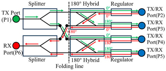
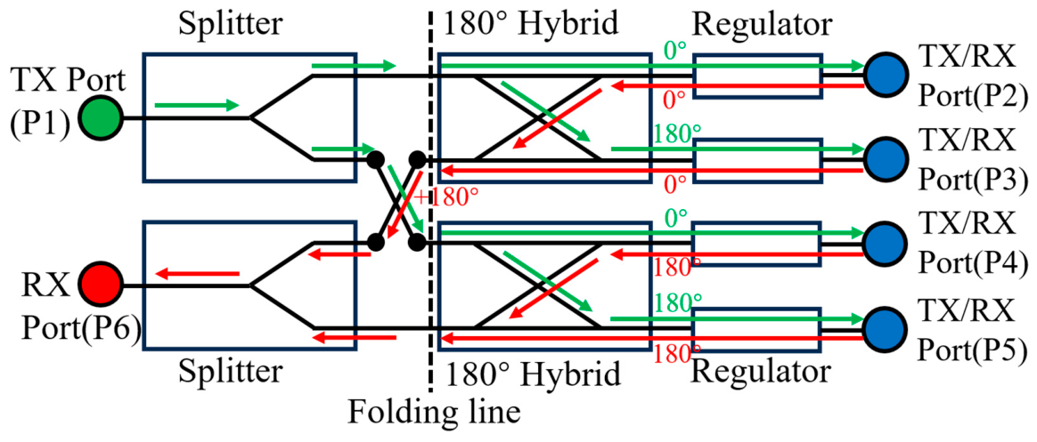
The schematic of the proposed transceiver system is shown in Figure 1. It consists of two splitters, two 180° hybrids, four polarization regulators, and four conical horn antennas. Ports 1 and 6 are standard WR-90 ports operating in the TE10 mode, while Ports 2–5 are circular waveguide ports operating in the TE11 mode. Specifically, Port 1 serves as the feeding port, Ports 2–5 are radiating ports connected to the conical horn antennas, and Port 6 is the output port for the received signals. The working principle is detailed as follows:
Figure 1.
Schematic diagram of the proposed transceiver system.
When a transmit signal is fed into Port 1, the splitter splits it into two in-phase signals with equal amplitude. These two signals are then respectively connected to two 180° hybrids, generating four equal-amplitude signals with phases of 0°, 180°, 0°, and 180°. These four signals are then converted into in-phase signals by the polarization regulators and radiated by the antennas.
Similarly, when the four antennas receive equal-amplitude and in-phase signals, the polarization regulators shift their phases to 0°, 0°, 180°, and 180°. After passing backward through the 180° hybrids, they are combined into two signals with a 180° phase difference.
One of the signal paths is designed with an extra λ/2 length to bypass the crossed waveguide. This aligns the phases of the two signals, allowing them to be directly combined to Port 6 via the splitter.
Furthermore, this additional λ/2 path design provides another critical advantage for port isolation. When a signal is fed into P1, the leakage energy originating from the two hybrids cancels each other out exactly in anti-phase before coupling back into P6. This destructive interference mechanism significantly enhances the isolation between the transmit and receive ports.
In the working mechanism of the proposed BFN, adjusting the phase after the hybrids is a major challenge. If circularly polarized antennas are arranged with a 90° relative rotation as in previous works, there will be a 3 dB power-combining loss. This is unacceptable for high-power microwave applications. Using traditional phase shifters will change the line length, causing the antennas to deviate from the same baseline. Therefore, it is necessary to design a rotary regulator.
For linearly polarized waves, a reversed electric field is equivalent to a 180° phase difference. Based on this, we can convert the TE10 mode in the rectangular waveguide to a coaxial waveguide TEM mode by using a transition inner conductor. A metal septum is then inserted in the middle of the coaxial waveguide. The inner diameter of the upper half of the waveguide is smaller than that of the lower half, generating a phase difference. When the phase difference reaches 180°, the wave is restored to circular waveguide TE11 mode. By fixing the coaxial waveguide section and rotating the septum section, the output electric field polarization direction can be adjusted. When the rotation angles of the two regulators differ by 180°, the phase of their output TE11 modes will also differ by 180°.
3. Simulation
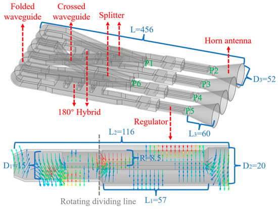
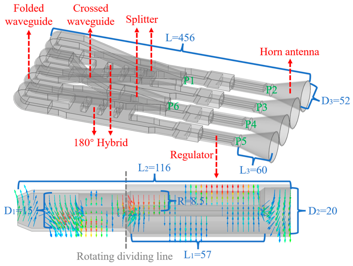
Based on the proposed BFN, a complete transceiver system is formed by integrating the designed waveguide splitters, hybrids, regulators, and horn antennas. The model of the overall system and the electric field diagram of the regulator are shown in Figure 2. As can be observed from the electric field distributions, the input TE10 mode is first converted into the TEM mode. Then, it is split into two components with different propagation velocities. At the end of the phase-shifting section, the electric field polarizations become co-directional, and the wave is ultimately output as the TE11 mode. The dimensions of the entire system are 456 mm × 222 mm × 62 mm. Due to the folded waveguide design, the system’s length is reduced by 1/3 without increasing profile height. Meanwhile, the side-by-side distribution of the horn antennas is well-suited for array configurations.
Figure 2.
Model of the proposed transceiver system and electric field diagram of the regulator. The units are all mm.
This is the first report of a polarization regulator employing a TE10-TEM-TE11 waveguide mode transition path. Compared with traditional mode converters, the proposed structure makes the following novel contributions:
Different from the L-type or ladder-type inner conductor transformation in the previous rectangular-coaxial conversion works, the transformation structure of this paper is a bent inner conductor. The benefits of doing so include:
1. Eliminating the edges and corners prevents the tip discharge effect, which significantly minimizes the risk of breakdown and enhances the power capacity.
2. Minimizing the cross-sectional area and reflection.
3. Increasing the bearing for the inner conductor to prevent deformation caused by the weight of the right end.
The coaxial-circular conversion is also different from the previous way of adding steps or baffles in the waveguide. This design innovatively adopts the phase-shifting method of changing the radius of the upper and lower parts of the partition. The end of the inner conductor uses a half sphere instead of a truncated cone as a transition. Such a structure also has several advantages, including:
1. No metal components blocking makes the passing efficiency maximum.
2. Radius difference can be adjusted at will. The length required for a phase shift of 180° is reduced to only 57 mm, which is equivalent to 1.9λ. The length of the whole converter is only 116 mm (3.9λ).
3. The spacious, smooth and non-redundant internal structure improves the power capacity.
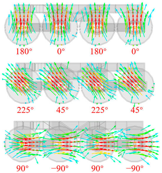
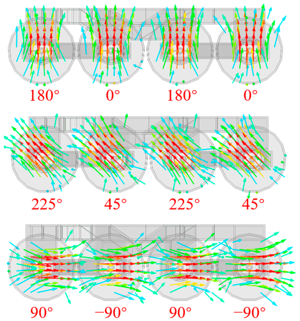
Electromagnetic simulations were performed using Ansys HFSS 2023 R1. The boundary conditions are set to radiation boundaries to simulate an open space. Figure 3 presents the electric field distributions at the horn aperture under different rotation angles of the regulator. It is evident that, as long as a 180° phase difference between the ports is maintained, the polarization direction of the radiated wave can be reconfigured to any arbitrary angle by rotating the regulators. The situation is similar when the system operates in the receiving state. The only difference is that the relative phases among the ports should be controlled to 0°, 0°, 180°, and 180°.
Figure 3.
Simulated electric field distributions at the horn aperture under various rotation angles of the regulator.
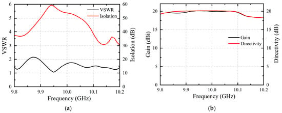
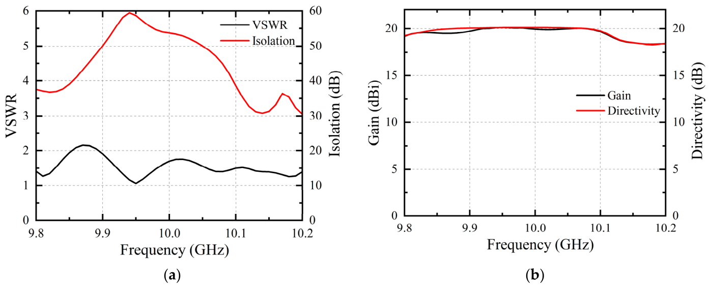
The voltage standing wave ratio (VSWR) and isolation (S61) of Port 1 are shown in Figure 4a and the gain and directivity are shown in Figure 4b. It can be seen that within the 9.8–10.2 GHz bandwidth, the designed transceiver system has a VSWR of less than 2 and an isolation of over 30 dB, reaching a maximum of 60 dB. In addition, the four horn antennas are well integrated, with a directivity of approximately 20 dB. The system loss is very small, making the gain close to the directivity. This overcomes the 3 dB loss problem in work [3].
Figure 4.
Simulation results of the transceiver system. (a) VSWR & Isolation; (b) Gain & Directivity.
The maximum electric field intensity concentrates on the inner conductor of the regulator, reaching approximately 5.2 × 10⁶ V/m at an input power of 500 kW. This value is lower than the breakdown electric field strength of sulfur hexafluoride (SF6), which is 8.9 × 10⁶ V/m. When the system is filled with SF6 gas at twice the atmospheric pressure, the power capacity of the system can be guaranteed to exceed 500 kW.
In summary, the designed transceiver system features a compact size, low reflection, high isolation, good radiation performance and high power capacity, demonstrating excellent overall performance and superiority.
4. Experiment
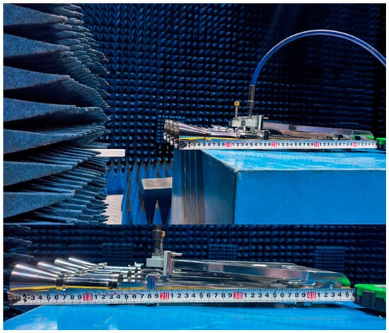
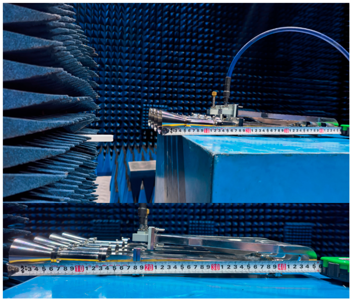
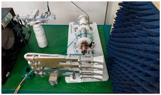
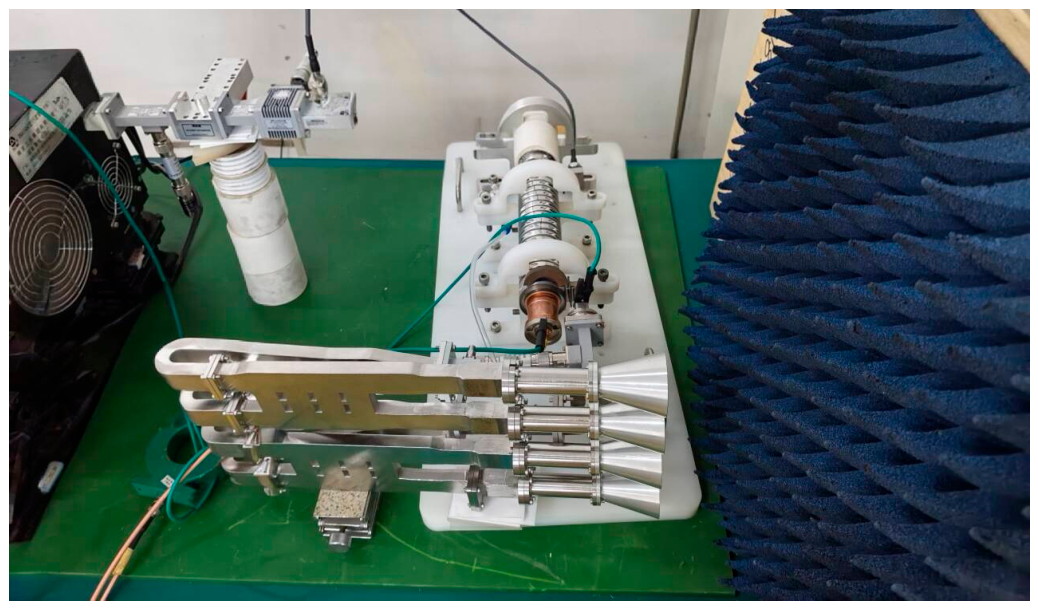
The designed transceiver system was then fabricated using stainless steel and aluminum as the primary materials. It was tested using an Agilent E8363C network analyzer (Santa Clara, CA, USA) and a microwave anechoic chamber. The fabricated prototype and the experimental environment are shown in Figure 5. The length of the prototype is 45.5 cm, which is consistent with the simulation model. The entire transceiver system has a compact structure and is easy to position and feed.
Figure 5.
Fabricated transceiver system prototype in the anechoic chamber.
To facilitate precise state switching, a specialized 180° mechanical track is integrated at the rotary split interface of the regulator. This design enables convenient and accurate manual rotation to exactly 180° or any desired intermediate angle. Furthermore, for large-scale array applications requiring numerous units, this adjustment mechanism can be readily upgraded to an electronically controlled rotation mode driven by motors and programmed algorithms. The feasibility and reliability of such an automated control scheme have already been successfully demonstrated in our other related projects.
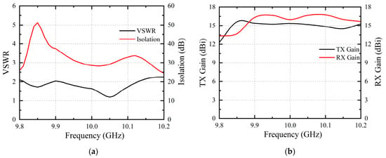
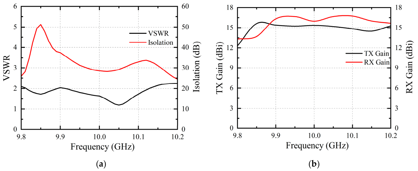
The VSWR and isolation measured by the network analyzer are shown in Figure 6a. The transmitting and receiving gains measured in the anechoic chamber are shown in Figure 6b. Within the 9.85–10.15 GHz band, the VSWR is less than 2.1 and the isolation is greater than 29 dB, which agrees with the design objectives. The transmitting and receiving gains are approximately 14.8–16.7 dBi. The discrepancies between the measured isolation and the simulated value, as well as the energy loss, are mainly caused by fabrication errors. Factors such as limited milling precision, the inner surface roughness of the waveguide, fabrication errors in the bent sections, and micro-gaps at the flange joints introduce unpredictable impedance mismatches and reflections. Improving the fabrication accuracy can further mitigate these issues.
Figure 6.
Measured results of transceiver system. (a) VSWR & Isolation; (b) Transmitting (TX) and receiving (RX) Gain.
To explicitly verify the high-power capacity, Port 1 of the fabricated prototype was fed by a high-power pulsed microwave source, as shown in the experimental setup in Figure 7. The pulse waveforms remained stable at a peak input power of 500 kW. Additionally, visual and acoustic inspections confirmed the absence of arcing or multipactor effects within the waveguide paths. These experimental observations definitively corroborate the simulation results, validating the 500 kW power-handling capability of the proposed system.
Figure 7.
Experimental setup fed by a high-power pulsed microwave source.
Table 1 compares this work with similar transceiver systems. It can be seen that even with a pure waveguide structure, the proposed system achieves good bandwidth and isolation. Among the few reported waveguide structures, the design in [15] suffers from an 8° beam deflection, and its power capacity is only theoretically calculated. The design in [17] is based on a resonant cavity structure, which severely limits its power capacity. Owing to the well-integrated horn and waveguide configuration, the transceiver system in this article exhibits better radiation performance and a higher power capacity. This provides it with a distinct advantage in high-power applications.
Table 1.
Comparison.
5. Conclusions
This paper proposes a high-power polarization-reconfigurable monostatic transceiver system based on a pure waveguide structure. A custom-designed polarization converter enables adjustment of the output polarization to an arbitrary angle. Measurements demonstrate that the system achieves a VSWR ≤ 2.1, an isolation of 29–52 dB, and transmitting and receiving gains of 14.8–16.7 dBi. Additionally, the compact structure and well-integrated antennas make it easy to install and form arrays.
In conclusion, the proposed system features high power capacity, low reflection, good isolation and radiation performance. It has significant potential for high-power microwave applications, such as long-distance communication and wireless power transfer.
Future endeavors will focus on developing broader-band components and refining manufacturing precision to further elevate the overall performance of the transceiver system. Concurrently, the rotation method can be advanced to an electronically controlled configuration to adjust the polarization direction more easily and quickly.
Author Contributions
Conceptualization, B.D., Y.Y. and H.C.; Methodology, B.D., Y.Y. and H.C.; Software, B.D.; Validation, B.D.; Formal analysis, B.D.; Investigation, B.D.; Resources, Y.Y. and H.C.; Data curation, B.D.; Writing—original draft, B.D.; Writing—review & editing, B.D., Y.Y. and H.C.; Visualization, B.D.; Supervision, Y.Y. and H.C.; Project administration, Y.Y. and H.C.; Funding acquisition, Y.Y. and H.C. All authors have read and agreed to the published version of the manuscript.
Funding
This research was funded by National Key Laboratory of Advanced Lasers and High Power Microwaves.
Data Availability Statement
The data presented in this study are openly available in https://dx.doi.org/10.21227/9acd-cj24.
Conflicts of Interest
The authors declare no conflict of interest.
Abbreviations
The following abbreviations are used in this manuscript:
| BFN | Beamforming network |
| VSWR | Voltage standing wave ratio |
| C-STAR | Co-channel simultaneous transmit and receive |
References
- Hovsepian, A.; Alwan, E.A.; Volakis, J.L. A Wideband, Scanning Array of Four-Arm Spiral Elements for Simultaneous Transmit and Receive. IEEE Antennas Wirel. Propag. Lett. 2020, 19, 537–541. [Google Scholar] [CrossRef] [Scilit]
- Etellisi, E.A.; Elmansouri, M.A.; Filipovic, D.S. Wideband Monostatic Simultaneous Transmit and Receive (STAR) Antenna. IEEE Trans. Antennas Propag. 2016, 64, 6–15. [Google Scholar] [CrossRef] [Scilit]
- Etellisi, E.A.; Elmansouri, M.A.; Filipovic, D.S. Wideband Monostatic Co-Polarized Co-Channel Simultaneous Transmit and Receive Broadside Circular Array Antenna. IEEE Trans. Antennas Propag. 2019, 67, 843–852. [Google Scholar] [CrossRef] [Scilit]
- Wu, D.; Li, Y.; Sun, Y.-X.; Lian, R.; Xiao, B.; Li, M. A Wideband Monostatic Co-Circularly Polarized Simultaneous Transmit and Receive Antenna Using Metasurface. In Proceedings of the 2024 15th Global Symposium on Millimeter-Waves & Terahertz (GSMM), Hong Kong, China, 20–22 May 2024. [Google Scholar]
- Elmansouri, M.A.; Kee, A.J.; Filipovic, D.S. Wideband Antenna Array for Simultaneous Transmit and Receive (STAR) Applications. IEEE Antennas Wirel. Propag. Lett. 2017, 16, 1277–1280. [Google Scholar] [CrossRef] [Scilit]
- Zhou, Z.; Li, Y.; Hu, J.; He, Y.; Zhang, Z.; Chen, P.-Y. Monostatic Copolarized Simultaneous Transmit and Receive (STAR) Antenna by Integrated Single-Layer Design. IEEE Antennas Wirel. Propag. Lett. 2019, 18, 472–476. [Google Scholar] [CrossRef]
- Ha, J.; Elmansouri, M.A.; Valale Prasannakumar, P.; Filipovic, D.S. Monostatic Co-Polarized Full-Duplex Antenna with Left- or Right-Hand Circular Polarization. IEEE Trans. Antennas Propag. 2017, 65, 5103–5111. [Google Scholar] [CrossRef] [Scilit]
- Fu, S.; Wang, Y.; Li, C.; Xu, Z. Dual-Circularly Polarized STAR Antenna Array with High Realized Gain and Enhanced Isolation. IEEE Antennas Wirel. Propag. Lett. 2024, 23, 4777–4781. [Google Scholar] [CrossRef] [Scilit]
- Ma, L.; Gu, C.; Mao, J. A Dual Circularly Polarized, Simultaneous Transmit and Receive (STAR) Common Aperture Antenna Array for Integrated Sensing and Communication. In Proceedings of the 2022 IEEE Conference on Antenna Measurements and Applications (CAMA), Guangzhou, China, 14–17 December 2022. [Google Scholar]
- Ranjbar Nikkhah, M.; Wu, J.; Luyen, H.; Behdad, N. A Concurrently Dual-Polarized, Simultaneous Transmit and Receive (STAR) Antenna. IEEE Trans. Antennas Propag. 2020, 68, 5935–5944. [Google Scholar] [CrossRef] [Scilit]
- Wu, D.; Sun, Y.-X.; Wang, B.; Lian, R. A Compact, Monostatic, Co-Circularly Polarized Simultaneous Transmit and Receive (STAR) Antenna with High Isolation. IEEE Antennas Wirel. Propag. Lett. 2020, 19, 1127–1131. [Google Scholar] [CrossRef] [Scilit]
- Wu, D.; Zang, Y.; Luyen, H.; Li, M.; Behdad, N. A Compact, Low-Profile Simultaneous Transmit and Receive Antenna with Monopole-Like Radiation Characteristics. IEEE Antennas Wirel. Propag. Lett. 2019, 18, 611–615. [Google Scholar] [CrossRef]
- Xie, M.; Yao, H.; Wei, X.; Tang, Y.; Wang, J.; Hu, D. Co-Aperture Dual-Circular-Polarized Patch Antenna for Simultaneous Transmit and Receive. IEEE Antennas Wirel. Propag. Lett. 2023, 22, 2745–2749. [Google Scholar] [CrossRef] [Scilit]
- Valale Prasannakumar, P.; Elmansouri, M.A.; Boskovic, L.B.; Ignatenko, M.; Filipovic, D.S. Wideband Quasi-Monostatic Simultaneous Transmit and Receive Reflector Antenna. IEEE Trans. Antennas Propag. 2020, 68, 2630–2637. [Google Scholar] [CrossRef] [Scilit]
- Ma, C.J.; Qian, R.R.; Zheng, S.Y.; Pan, Y.M. Wideband Millimeter-Wave Co-Linearly Polarized In-Band Full-Duplex Open-Ended Waveguide Antenna. IEEE Trans. Antennas Propag. 2025, 73, 9854–9867. [Google Scholar] [CrossRef] [Scilit]
- Park, A.J.; Pfeiffer, C.C.; Chabanov, A.A.; Grbic, A. Simultaneous Transmit-Receive Horn Antenna Based on a Nonreciprocal Metasurface with Embedded Magnetic Bias. In Proceedings of the 2024 IEEE International Workshop on Antenna Technology (iWAT), Sendai, Japan, 15–18 April 2024. [Google Scholar]
- Lin, J.-Y.; Yang, Y.; Wong, S.-W.; Chen, R.-S. In-Band Full-Duplex Filtering Antenna Arrays Using High-Order Mode Cavity Resonators. IEEE Trans. Microw. Theory Tech. 2023, 71, 1630–1639. [Google Scholar] [CrossRef] [Scilit]
- Hernandez, C.A.M.; Boskovic, L.B.; Elmansouri, M.A.; Ignatenko, M.; Filipovic, D.S. Fixed and Steerable Beam Dual-Polarized Lens Antenna with High Tx to Rx Isolation. IEEE Trans. Antennas Propag. 2021, 69, 7213–7221. [Google Scholar] [CrossRef] [Scilit]

Disclaimer/Publisher’s Note: The statements, opinions and data contained in all publications are solely those of the individual author(s) and contributor(s) and not of MDPI and/or the editor(s). MDPI and/or the editor(s) disclaim responsibility for any injury to people or property resulting from any ideas, methods, instructions or products referred to in the content. |
© 2026 by the authors. Licensee MDPI, Basel, Switzerland. This article is an open access article distributed under the terms and conditions of the Creative Commons Attribution (CC BY) license.