


Abstract
With the continuous advancement of ocean exploration and development, energy supply for underwater electronic equipment has become a key bottleneck restricting long-term operation. Traditional wired power supply and battery-powered operation suffer from corrosion, high maintenance costs, limited endurance, and replacement difficulties. Underwater ultrasonic wireless power transfer (UUWPT) achieves contactless electric–acoustic–electric conversion via piezoelectric transducers. It offers unique advantages, including insensitivity to electromagnetic interference, metal-penetration capability, excellent directivity, and medium-to-long-distance transmission. This paper systematically reviews the technical principles and development history of UUWPT. We trace its evolution from early feasibility verification, through theoretical improvements, to current system engineering and industrialization. Key frontier research directions are highlighted, such as MIMO/MISO arrays, simultaneous wireless power and data transfer (SWPDT), adaptive tuning, and novel transducer structures. Application prospects in marine monitoring, AUV endurance replenishment, marine energy development, and the Internet of Underwater Things are also analyzed. Finally, we discuss remaining challenges, including the trade-off between transmission efficiency and distance, insufficient adaptability to complex marine environments, and the lack of standardized system frameworks. Future research should prioritize high-efficiency long-distance power transfer, system reliability, and engineering applications.
1. Introduction
With the deepening of marine resource development and the continuous progress of underwater detection technology, a large number of underwater electronic devices and sensor networks are now deployed in the marine environment. The energy supply of these devices has become a key factor restricting their long-term and stable operation. Wired power supply requires submarine cables—a solution that is not only costly in deep-sea conditions but also subject to seawater corrosion, connector aging, and difficult maintenance. Battery-powered operation eliminates the need for cables, yet battery capacity is limited. Once depleted, equipment must be salvaged for battery replacement, or a submersible must perform underwater plugging/unplugging operations. Both approaches are time-consuming and labor-intensive, and neither is feasible for deep-sea observation nodes that require continuous long-term operation [1].
Underwater wireless power transfer (UWPT), developed in recent years, supplies power to underwater equipment through contactless transfer. It fundamentally overcomes the drawbacks of wired transmission regarding safety, reliability, flexibility, and concealment, and shows great application potential in marine engineering, underwater detection, marine monitoring networks, and other fields. At present, UWPT technologies mainly include inductive wireless power transfer (mm scale), magnetic resonance coupling wireless power transfer (cm scale), capacitive power transfer (cm scale), lightwave power transfer (m scale), and ultrasonic coupling wireless power transfer (m scale) [2,3,4,5]. Among these, underwater capacitive power transfer (UCPT) utilizes high-frequency electric fields for energy transmission. It eliminates eddy-current losses in seawater and offers simple coupler structures that are easy to seal [4]. Underwater lightwave power transfer (LPT) enables simultaneous energy harvesting and data communication through visible light, which is particularly suitable for scenarios requiring high-speed data links [5].
To clarify the positioning of ultrasonic power transfer, Table 1 compares the major underwater wireless power transfer routes using a unified set of criteria. The ranges in the table should be interpreted as typical engineering regimes rather than fixed physical limits, because practical performance strongly depends on coupling geometry, water quality, packaging, alignment, and the adopted power-electronics topology.
Table 1.
Systematic comparison of major underwater wireless power transfer technologies.
Compared with other wireless power transfer technologies, underwater ultrasonic wireless power transfer (UUWPT) offers several distinct advantages. It is unaffected by electromagnetic interference, can penetrate metal barriers, and is especially suitable for scenarios requiring sealed metal enclosures. UUWPT transmits energy in the form of mechanical waves (ultrasound). Compared with electromagnetic waves, ultrasound provides a more concentrated beam and better directivity in energy transmission. At a transmission distance of 1 m and an input power of 10 W, an inductive system spreads energy over 360° and achieves an efficiency of only 0.5%, whereas a UUWPT system concentrates energy within a 20° beam and can reach an efficiency of up to 20% [9]. Compared with UCPT and LPT, UUWPT exhibits clear advantages in scenarios requiring sealed metal isolation or long-distance power supply. While UCPT is limited by the need for close proximity between coupler plates, and LPT suffers from severe light absorption and scattering in turbid waters, UUWPT can achieve meter-scale transmission with excellent directivity and metal-penetration capability [4,5,9].
The efficiency comparison with IPT should therefore be read under the assumptions used in the cited experimental comparison: aligned transmitter/receiver structures, fixed input power and distance, controlled water conditions, and a specific coil/transducer geometry. It is not intended to imply that every IPT link at 1 m will be limited to 0.5% or that every ultrasonic link will reach 20%. Rather, it illustrates the different scaling mechanisms of magnetic-field spreading and acoustic directivity in seawater.
In underwater environments, the energy loss of ultrasound during transmission is two to three orders of magnitude smaller than that of electromagnetic waves and light waves. Low-frequency UUWPT has already achieved energy transmission over tens of meters, offering the possibility of long-distance power supply for underwater equipment. In recent years, progress in piezoelectric material technology and continuous optimization of system design have enabled UUWPT to gradually move from theoretical research to engineering applications.
However, the development of UUWPT still faces many challenges. At the technical level, the contradiction between transmission efficiency and distance has not yet been effectively resolved. At the engineering level, the environmental adaptability and reliability of the system need further improvement. At the application level, the standardization system lags behind, restricting large-scale promotion and deployment. Therefore, an in-depth analysis of the current state of this technology and a systematic review of its technical principles and research progress are of great significance for promoting the further development of UUWPT.
This paper aims to systematically review the development status and future trends of UUWPT. The main contributions of this review are as follows:
(1) We trace the complete evolution of UUWPT from its theoretical origins in underwater acoustics (1826–Cold War era) to its modern emergence in the 21st century. We identify three distinct developmental stages: feasibility verification (pre-2015), system engineering (2016–2020), and industrial application expansion (2021–present). This historical perspective contextualizes current advances within the broader trajectory of underwater acoustic technology.
(2) We systematically analyze and categorize four frontier research directions—MIMO/MISO array power transfer, simultaneous wireless power and data transfer (SWPDT), intelligent adaptive tuning, and novel transducer structures—highlighting their technical principles, recent breakthroughs, and interconnections. A comparative analysis of representative MISO/MIMO systems from domestic and international research is provided to identify performance gaps and optimization strategies.
(3) We critically assess the technical bottlenecks and engineering challenges facing UUWPT. These include the efficiency–distance trade-off, the frequency-selection dilemma, impedance-matching complexity in dynamic environments, and marine environmental adaptability issues (biofouling, corrosion, multipath propagation). We further discuss the specific requirements and technical difficulties across six major application domains, from marine monitoring to medical implants.
By consolidating these perspectives, this review is expected to provide valuable references for researchers and engineers seeking to advance UUWPT toward high-efficiency, long-distance, and robust engineering applications.
2. Technical Principles and System Structure
2.1. Basic Working Principle of UUWPT
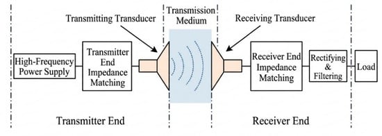
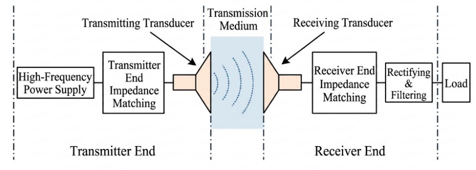
The basic structure of a UUWPT system is shown in Figure 1. During operation, a high-frequency power supply at the transmitter side generates an alternating current signal of a specific frequency. This signal is amplified by a power amplifier and drives the transmitting transducer. The transmitting transducer converts electrical energy into mechanical vibration via the inverse piezoelectric effect, thereby exciting ultrasound in the water. The ultrasound propagates through the water as mechanical waves. At the receiver side, the receiving transducer converts the acoustic energy back into electrical energy using the direct piezoelectric effect. The resulting electrical output is then rectified, filtered, and regulated to supply the load [16].
Figure 1.
Block diagram of the UUWPT system showing the electric–acoustic–electric energy conversion chain.
Physically, this system realizes a cross-medium energy conversion chain. Electrical energy from the high-frequency power supply is first converted into mechanical vibration through the inverse piezoelectric effect of the transmitting transducer. It then propagates as acoustic waves through the water medium and is finally reconverted into electrical energy by the direct piezoelectric effect of the receiving transducer to power the underwater load.
The physical principles of audible sound and ultrasound for underwater wireless power transfer are identical; the difference lies solely in the frequency range. Sound waves refer to vibrations within the human hearing range (approximately 20 Hz–20 kHz), whereas ultrasound has frequencies above 20 kHz. In practical engineering applications, UUWPT systems typically operate from 20 kHz to several MHz. Lower frequencies help reduce propagation loss and extend transmission distance, whereas higher frequencies allow smaller transducer sizes and improved directivity. Striking a balance between these factors is a key design consideration [10].
The propagation of ultrasound in water follows acoustic propagation laws. For a single circular piston transducer, the sound pressure amplitude at any point in a liquid transmission medium can be expressed as:
where is the sound pressure amplitude at the point, is the angular frequency of the sound wave (, with the operating frequency), is the density of the liquid transmission medium (approximately 1025 kg/m3 for seawater), is the particle vibration velocity, is the transducer radius, is the first-order Bessel function, is the wavenumber (, where is the acoustic wavelength), is the angle between the line connecting the point and the transducer center and the transducer axis, and is the distance from the point to the transducer center [17].
The sound pressure amplitude on the transducer axis can be simplified as:
where is the speed of sound in the liquid transmission medium (approximately 1500 m/s in seawater) and r is the distance from the focal point to the transducer center.
Equations (1) and (2) are derived from a baffled circular piston model. The underlying assumptions include steady-state sinusoidal excitation, linear small-signal acoustics, a homogeneous fluid medium, and an axisymmetric radiation field. They neglect nonlinear effects, cavitation, strong boundary reflections, transducer packaging, and temperature or salinity gradients. In real seawater, attenuation and multipath terms should be added to the propagation model when the transmission distance or boundary complexity increases.
2.2. Equivalent Circuit Model of Piezoelectric Transducer
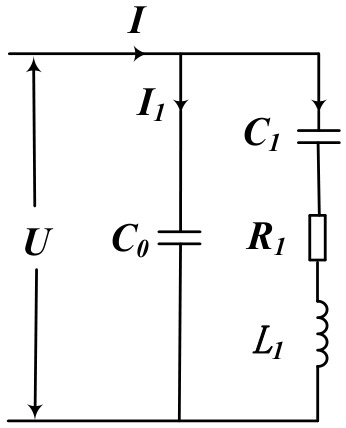
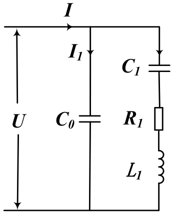
The transducer is the core component of a UUWPT system. Its performance largely determines the overall transmission efficiency and power capacity. The most commonly used modeling approach is the Butterworth–Van Dyke (BVD) equivalent circuit, which represents the piezoelectric transducer as a first-order two-port network, as shown in Figure 2.
Figure 2.
Butterworth–Van Dyke (BVD) equivalent circuit model of a piezoelectric transducer.
Physically, the BVD model captures the electromechanical coupling behavior of the piezoelectric transducer. It separates the electrical and mechanical energy storage mechanisms into distinct circuit branches. This separation enables quantitative analysis of the transducer’s resonance characteristics and impedance behavior.
The model consists of two parallel branches. The dynamic branch is composed of dynamic resistance , dynamic inductance , and dynamic capacitance ; it reflects the mechanical vibration characteristics of the transducer. The static branch is composed of static capacitance ; it reflects the inherent capacitance between the transducer electrodes. The relationships between these parameters and the physical structure of the transducer are as follows [18]:
where is the permittivity of the piezoelectric material under constant stress (in F/m), is the effective area of the transducer electrodes (in m2), and is the thickness of the transducer (in m). For the commonly used PZT-4 piezoelectric ceramic, .
where is the density of the piezoelectric material (in kg/m3), is the electromechanical coupling coefficient of the piezoelectric transducer, is the elastic modulus of the piezoelectric material under constant electric displacement (in Pa), is the resonance frequency of the transducer (in Hz), and is the mechanical quality factor of the transducer.
The series impedance of the dynamic branch is , and the static capacitance is connected in parallel with . Therefore, the input impedance is:
When the transducer operates at the resonance frequency , we have . Then the dynamic branch impedance is , and the input impedance simplifies to . At this point, the electro-acoustic conversion efficiency of the transducer is highest. This property is crucial in system debugging. In practical engineering, an impedance matching network is often needed to tune the transducer to resonance for optimal power transfer.
Besides the BVD model, some researchers use the Mason equivalent circuit or the KLM model for higher precision. The latter provides better accuracy in broadband response prediction but involves more complicated parameter extraction [19]. The BVD model is most useful for narrowband operation around a dominant resonance and for circuit-level matching design. However, it cannot fully describe multilayer acoustic stacks, broadband thickness-mode behavior, strong modal coupling, high-power thermal drift, or pressure-dependent material parameters. Mason and KLM models are therefore preferable when the transducer contains matching layers or backing layers, when the frequency response is broadband, or when accurate modeling of acoustic loading and wave propagation inside layered media is required. Due to space limitations, these models are not further expanded here.
2.3. Equivalent Circuit of UUWPT System
The UUWPT system includes the transmitter circuit, the receiver circuit, and the mechanical wave energy transmission channel. This channel consists of the transmitting transducer, the water medium, and the receiving transducer. Through electromechanical and acoustoelectric equivalence, these parts can be unified into a single circuit modeling framework [20], as shown in Figure 3.
Figure 3.
Unified equivalent circuit model of the complete UUWPT system.
Physically, this unified model allows the entire energy transfer process to be analyzed within a single circuit-theoretic framework. The process encompasses electrical excitation at the transmitter, electromechanical conversion, acoustic wave propagation in water, acoustoelectric conversion at the receiver, and final electrical output. This framework thereby reveals the power loss distribution across each stage.
In this model, the transmitting and receiving transducers are represented by BVD equivalent circuits. The acoustic wave propagation in the water medium is represented by a transfer matrix or two-port network whose parameters are closely related to the transmission distance, the medium attenuation coefficient, and the acoustic impedance. Incorporating the whole system into a unified circuit model facilitates the analysis of power loss distribution at each stage. It also provides a theoretical basis for impedance matching and efficiency optimization. The output power of the system can be expressed as:
where is the control coefficient; with being the series resonance angular frequency of the transducer; and .
Equation (6) assumes steady-state operation near the selected resonance, linear electromechanical conversion, a fixed acoustic channel, and a load that can be represented by an equivalent impedance. When the receiver moves, the flow velocity changes, or the acoustic path contains strong reflectors, the channel transfer matrix becomes time-varying. The matching network must then be updated using feedback from voltage-current phase, received power, or acoustic pilot signals.
Table 2 summarizes the main energy loss sources in each part of the UUWPT system. This summary is valuable for understanding the efficiency bottlenecks and optimization directions.
Table 2.
Energy loss sources in each part of a UUWPT system, with indicative relative impact and mitigation levers.
3. Development History
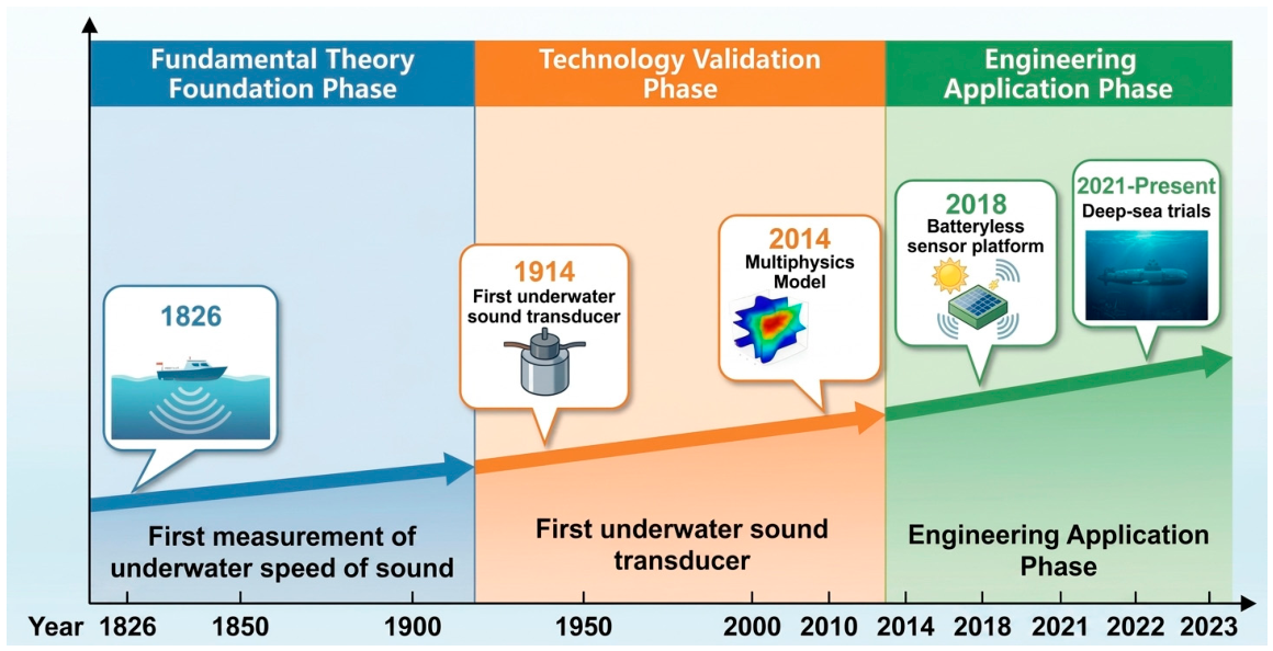
The evolution of underwater ultrasonic wireless power transfer technology is closely linked to the development of modern underwater acoustics. In 1826, Swiss physicist J.D. Colladon and French mathematician C.F. Sturm first measured the speed of sound in Lake Geneva, laying the foundation for underwater acoustic research. In 1914, American scientist R.A. Fessenden developed the world’s first moving-coil underwater acoustic transducer and used it to detect an iceberg 2000 m away. This achievement marked the transition of underwater acoustic technology from theory to practical application. In 1916, Langevin used a steel–quartz–steel sandwich transducer to obtain the first underwater ultrasonic echo. The following year, he and Boyle in Britain detected echoes from a submarine. During the Cold War, the nuclear submarine competition between the United States and the Soviet Union further advanced underwater acoustics. It gradually formed a mature theoretical system that provided the necessary tools and engineering experience for the later emergence of UUWPT.
In the mid-20th century, with the development of wireless communication technology, the concept of wireless power transfer began to attract attention. Early research focused mainly on electromagnetic waves and electromagnetic induction. In the 1960s, researchers began exploring the potential of acoustic waves for energy transmission, particularly in medical ultrasound therapy and industrial ultrasonic machining. Although those applications differed from underwater power transfer, they provided important scientific knowledge for understanding the basic mechanisms of acoustic energy transmission. In the 1990s, researchers attempted to combine wireless power transfer with underwater application scenarios. At that time, the mainstream technical routes were still electromagnetic induction and magnetic resonance coupling. Although the transmission distances were limited, these efforts provided useful references for subsequent technological evolution.
Prior to underwater-specific research, early ultrasonic energy transfer studies in medical therapy, implantable devices, and industrial processing also accumulated crucial knowledge for UUWPT. Medical ultrasound therapy, implantable ultrasonic powering, ultrasonic machining, and acoustic energy transfer through metal walls all demonstrated that acoustic waves can deliver usable energy across media without electrical contact. These studies were not direct underwater power-supply demonstrations. Nevertheless, they established the design principles of acoustic impedance matching, piezoelectric receiver loading, safe acoustic-intensity limits, and transducer miniaturization. These principles later became central to underwater ultrasonic links [16,21,22,23].
Modern UUWPT technology began to be explored in the 21st century. Researchers were motivated by the inherent drawbacks of other WPT technologies underwater, such as short transmission distance and high environmental sensitivity. They began to investigate the possibility of using UUWPT for underwater energy transfer [24].
The period before 2015 can be regarded as the embryonic stage of UUWPT. The core goal at this stage was to answer a fundamental question: can ultrasound achieve effective wireless power transfer underwater? In 2014, Shima Shahab and Alper Erturk published a landmark study. They established for the first time a complete multi-physics model of acoustic-piezoelectric coupling. They quantified the relationships among input power, transmission distance, and output electrical power, and derived optimal impedance and load tuning strategies. This work provided a modeling paradigm for subsequent research in the field [11]. Around the same time, Maurice G.L. Roes et al. published a review article on acoustic energy transfer [21]. They pointed out that, compared with other underwater WPT technologies, ultrasonic transfer offers advantages such as immunity to electromagnetic interference and longer transmission distance. This clarified the distinct advantages of UUWPT from a technical positioning perspective.
The period from 2016 to 2020 marked a critical transition from theory to system-level implementation. Research focus shifted from “whether it works” to “how to make it work better.” Array transducer technology, impedance matching network optimization, and environmental adaptability improvement became hot topics. In 2018, a team at Northeastern University (USA) achieved an important breakthrough in UUWPT engineering. They successfully developed the world’s first long-range ultrasound-powered underwater sensor node platform (Figure 4). This platform integrated simultaneous power and data transfer through ultrasonic supply. The transmission efficiency was about 50%, and the transmission distance far exceeded that of other technical solutions at the time [25]. The platform demonstrated that ultrasonic energy can simultaneously power sensors and support bidirectional data communication through metal barriers. This confirmed the practical viability of acoustic wireless powering in underwater environments. During this stage, the transmission efficiency of UUWPT increased from less than 10% to 40–70%, and the transmission distance expanded from centimeters to meters. These achievements preliminarily verified engineering feasibility.
Figure 4.
Architecture of the battery-less underwater sensor node platform developed by Northeastern University.
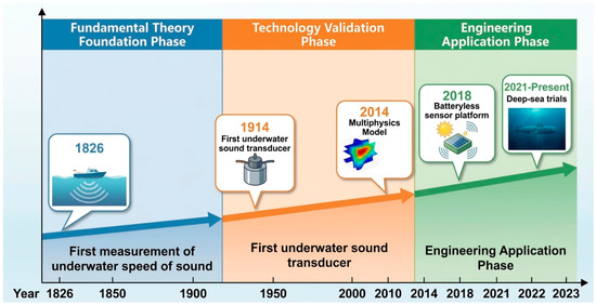
From 2021 onward, UUWPT technology has gradually expanded toward engineering applications. The research focus at this stage is on improving system performance, expanding application scenarios, and promoting industrial implementation. In terms of transmission efficiency, low-power systems under laboratory conditions have continuously improved efficiency through impedance transformation and transducer optimization [26]. In terms of transmission distance, Liao et al. achieved a received power of 433 mW and an efficiency of 17% at a distance of 35 cm. This verified the feasibility of medium-distance UUWPT systems [12]. Regarding high-power deep-sea applications, a related deep-sea (4000 m) wireless simultaneous power and data transfer system achieved 4.06 kW of power and 500 kbps full-duplex data transmission [27]. This indicates that integrated underwater power and data technology has preliminarily demonstrated capability for extreme environments. Ozeri et al. achieved a power level of 100 mW with a maximum efficiency of 39.1% in implantable transcutaneous ultrasonic energy transfer [22]. This provides a reference prototype for the design of cross-medium ultrasonic power transfer systems. As shown in Figure 5, this roadmap illustrates how UUWPT has evolved from foundational acoustic theory to a maturing engineering discipline, with each phase building upon the theoretical and experimental achievements of the preceding era. The key milestones are further summarized in Table 3.
Figure 5.
Evolutionary roadmap of UUWPT technology across three developmental phases.
Table 3.
Key milestones in UUWPT technology development.
4. Research Hotspots and Application Prospects
4.1. Technical Research Hotspots
Current research hotspots in underwater ultrasonic wireless power transfer technology mainly focus on the following key technical directions. Some of these have already achieved remarkable progress.
(1) MIMO/MISO Array Power Transfer Technology
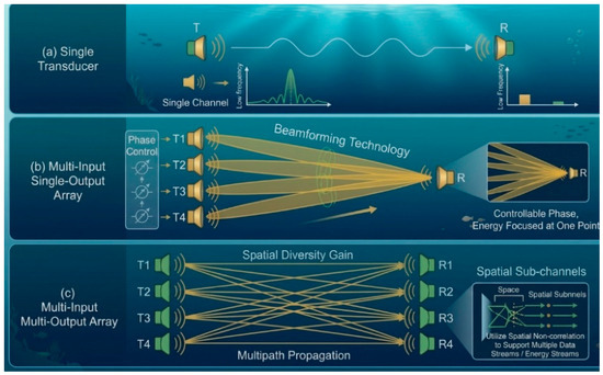
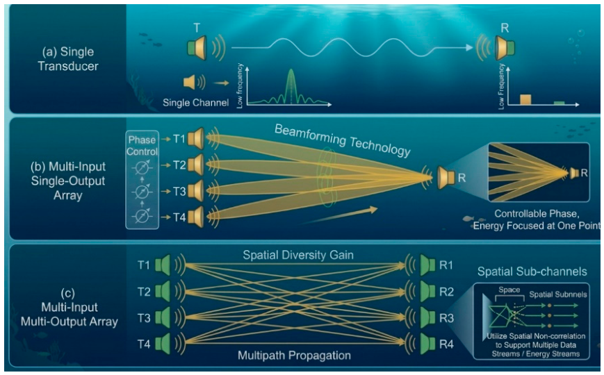
Multiple-input multiple-output (MIMO) and multiple-input single-output (MISO) array power transfer technology is currently one of the most prominent research topics in the UUWPT field. This approach replaces traditional single transducers with multiple transmitting elements and one or more receiving elements. By employing spatial diversity and beamforming techniques, it improves transmission efficiency, extends transmission distance, and enhances anti-interference capability [28]. Physically, array-based transmission reshapes the acoustic field distribution by controlling the phase and amplitude of each transducer element. It converts destructive interference into constructive interference at the receiver location, thereby increasing the spatial energy density available for capture. A conceptual comparison of single-transducer versus array-based transmission is shown in Figure 6.
Figure 6.
Conceptual comparison of single-transducer versus array-based ultrasonic power transmission.
It is worth noting that MIMO/MISO array concepts have also been extensively studied in electromagnetic coupling WPT systems. For instance, Kang et al. proposed a magnetic field projection and phase control scheme for a 2 × 2 planar transmitting coil array. This scheme enables closed-loop detection of multiple receivers’ positions and orientations within 25 ms through current phase modulation [29]. Pahlavan et al. developed an overlapped resonator array structure that eliminates blank spots in the electromagnetic field distribution. It achieves uniform power transmission with only 10% power variation for free-moving applications [30]. These electromagnetic array techniques primarily operate in the kHz to MHz bands and focus on near-field magnetic field shaping. In contrast, UUWPT arrays operate in the acoustic frequency range (tens of kHz to MHz). They manipulate acoustic wave interference through transducer phase control, facing unique challenges such as underwater multipath propagation and medium attenuation.
From a developmental perspective, MISO/MIMO array power transfer was not initially an independent technical route for UWPT. It was gradually introduced after single-transducer point-to-point power transfer encountered limitations in transmission distance, receiving area, and attitude misalignment. Early UWPT research focused mainly on piezoelectric transducer modeling, impedance matching, and efficiency improvement. With the maturation of application scenarios such as the Internet of Underwater Things, AUV autonomous replenishment, and underwater charging stations, the research focus gradually shifted toward using multiple transducers to spatially reshape the acoustic field and increase the received power on the secondary side. Mohsan et al. identified MIMO WPT as an important direction for improving AUV endurance and underwater self-charging networks [31]. Martinez et al. also pointed out in a review of wireless power supply for UUVs that misalignment tolerance, charging station deployment, and multi-technology synergy are core issues for underwater engineering replenishment [32].
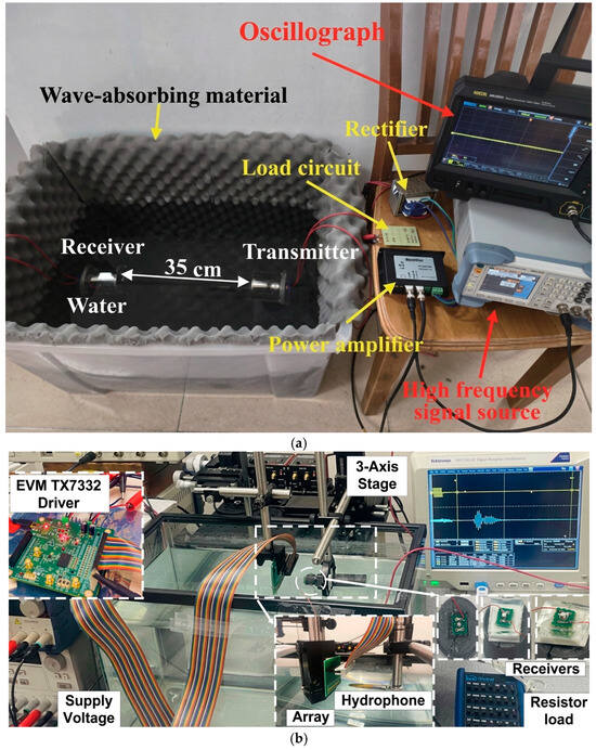
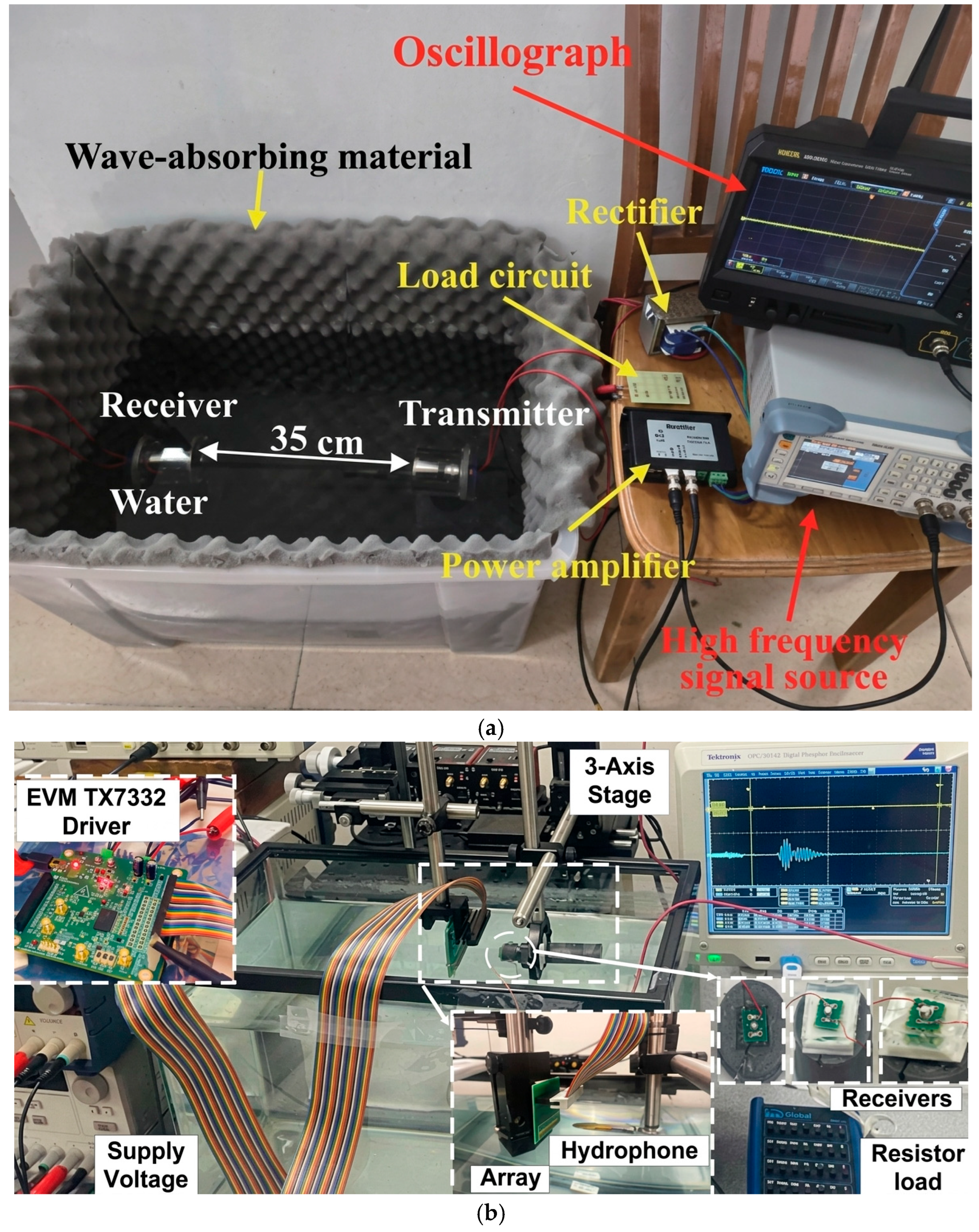
Considerable research has been conducted on MIMO/MISO array power transfer. Figure 7 shows photographs of typical underwater ultrasonic wireless power transfer experimental platforms. Freychet et al. proposed an acoustic energy transfer structure with multiple transmitters focusing on a single receiver. By optimizing the amplitude and phase of the excitation signals of each transmitter, they converted the acoustic waves at the receiver from destructive to constructive interference. In experiments, the transmission power and efficiency approximately doubled under aligned conditions. Under misalignment, the power increased by up to about 45 times. These results demonstrate that MISO array structures have significant advantages in misalignment tolerance and small-size receivers [33]. Kashani et al. designed and tested a 16-element ultrasonic phased array wireless power link. They verified the feasibility of focusing, steering, and receiver misalignment compensation. This work provides a methodological reference for using phased arrays for dynamic beam control in UUWPT [34]. Liu et al., starting from the spatial distribution of underwater ultrasonic energy radiation, proposed incorporating acoustic power distribution, side lobes, and energy concentration into the evaluation system. They indicated that array geometry, operating frequency, and receiver position together determine the actual energy arrival rate [35]. For reference, Table 4 summarizes representative SISO or point-to-point acoustic power transfer studies as a performance baseline, while Table 5 compares the performance of typical MISO/MIMO array power transfer systems from domestic and international research.
Figure 7.
Photographs of underwater ultrasonic wireless power transfer experimental platforms. (a) SISO system (reprinted with permission from Liao et al. [12]). (b) 16 element phased array system (reprinted with permission from Kashani and Kiani [34]).
Table 4.
Standardized comparison of representative SISO or point-to-point acoustic power transfer studies.
Table 5.
Standardized comparison of representative array-based and related power transfer systems.
Overall, MISO is more suitable for ensuring stable energy delivery to a single or small receiving transducer. It offers relatively higher engineering maturity. MIMO further targets scenarios such as multiple receivers, multiple AUVs, or coordinated multi-beam energy and information transfer. However, many problems in MIMO remain unsolved. Currently, this technology has evolved from simple efficiency improvement toward a systematic approach encompassing array acoustic field control, dynamic misalignment tolerance, and multi-node collaborative replenishment.
In practical deployment, MISO is preferred when the receiver is unique, small, low-power, or mounted on an AUV docking interface. This is because MISO provides transmit-side diversity without requiring multiple receiver channels. MIMO is preferable when several receivers must be powered simultaneously, when spatial power shaping is required over a wider area, or when energy and data beams must be separated. However, MIMO requires channel estimation, phase synchronization among transducers, receiver identification, and real-time energy allocation. These requirements increase the number of power amplifiers, feedback channels, and control computations as the array size grows [33,34,35].
(2) Simultaneous Wireless Power and Data Transfer
Underwater equipment requires not only electrical power supply but also the exchange of commands, status, and sensor data with the control station. If energy transfer and data communication can share the same physical link, the integration and reliability of the system will be significantly improved [36]. Simultaneous wireless power and data transfer (SWPDT) is another research focus in current UUWPT development. The mainstream technical routes are as follows.
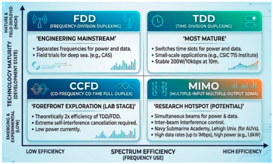
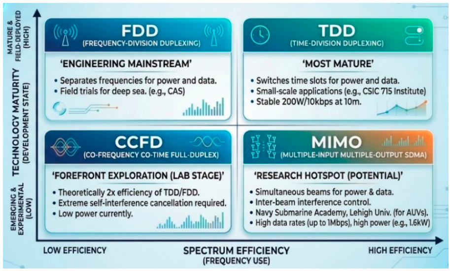
Time-division duplex (TDD) and frequency-division duplex (FDD) are common link organization methods for simultaneous power and data transfer. A related review categorizes frequency-domain, time-domain, and modulation-coupling schemes for power and data transmission as an important route for SWPDT [37]. The aforementioned deep-sea 4000 m system adopted an integrated design of wireless power and full-duplex data transmission. It achieved 4 kW power supply and a high-speed data link [27].
In addition to acoustic and electromagnetic approaches, lightwave-based simultaneous power and data transfer has emerged as a promising alternative for underwater applications. Palitharathna et al. proposed a lightwave power transfer-enabled cooperative NOMA system. In this scheme, seabed sensors harvest energy from destination-transmitted lightwaves while performing full-duplex data communication [5]. The scheme optimizes the time-splitting parameter between energy harvesting and information transmission, achieving significant performance gains over half-duplex operation. However, lightwave transfer is highly susceptible to water turbidity, absorption, and misalignment. These factors limit its practical deployment range [5].
In underwater acoustic and underwater sensor network scenarios, the SWIPT/SWPDT concept has also been introduced for underwater acoustic communication and underwater node power supply. Schemes such as time-reversal NOMA, full-duplex transmission, and multi-channel coupling can be used to reduce mutual interference between energy transmission and data links [38,39,40]. In addition, co-frequency co-time full-duplex (CCFD) simultaneous power and data transfer represents a more advanced direction. Its spectrum utilization is theoretically twice that of TDD and FDD. However, self-interference cancellation is very difficult, and currently only low-power transmission can be achieved. This approach remains at the laboratory exploration stage [40]. From a physical standpoint, the duplexing strategy determines how the shared acoustic channel is partitioned between power and data streams. It directly affects the spectral efficiency, power transfer continuity, and implementation complexity of the integrated system.
The main technical trade-off is that the power carrier is intentionally strong, while the data signal must preserve modulation fidelity. Interference arises from power-amplifier switching harmonics, rectifier load modulation, shared-transducer impedance variation, acoustic leakage between the power and data bands, and self-interference in full-duplex operation. Increasing the power-carrier amplitude improves harvested energy but may compress the receiver front end or raise the noise floor of the data link. Increasing data modulation depth improves communication reliability but can introduce ripple in the harvested DC power. Practical mitigation methods include guard bands, notch and band-pass filtering, TDD/FDD separation, orthogonal carriers, adaptive self-interference cancellation, and compensation topologies that isolate the power and data channels [37,38,39,40]. A comparison of the four main SWPDT duplexing strategies is shown in Figure 8.
Figure 8.
Comparison of four SWPDT duplexing strategies.
(3) Intelligent Adaptive Technology and New Materials
In addition to array power transfer and simultaneous power and data transfer, intelligent adaptive technology and new material applications are also active research directions.
Researchers are developing intelligent systems that can automatically adjust operating parameters according to environmental changes. For example, dynamic frequency optimization or frequency tracking allows the system to identify a favorable operating band under varying transmission distances, array structures, salinities, temperatures, and depths [13]. This capability is important for maintaining stable energy transmission in the dynamically changing marine environment.
A practical adaptive UUWPT controller can be organized as a three-loop system. First, a frequency-tracking loop searches around the transducer resonance and selects the frequency that maximizes received power while respecting attenuation and cavitation constraints [13,14]. Second, an impedance-matching loop measures the voltage-current phase angle or input admittance. It then switches capacitor or inductor banks, adjusts a tunable matching network, or changes the inverter operating point so that the transducer operates close to resonance. Third, an acoustic-field loop uses received-power feedback, pilot tones, or echo-based position estimation to update array phase and amplitude under misalignment or flow-induced motion. Recent work on misalignment-oriented optimization, high-power-density underwater sensor powering, and dynamic frequency optimization indicates that closed-loop control is becoming as important as the transducer hardware itself [8,13,14,41].
Regarding new materials and novel structures, acoustic holography and metamaterial structures also provide new ideas for the future development of UUWPT systems. Relevant studies have used acoustic holographic structures to reconstruct and focus the energy field of ultrasound. This enables more flexible energy field construction in contactless ultrasonic energy transmission systems, representing a promising direction for future UUWPT research [42].
4.2. Application Trends
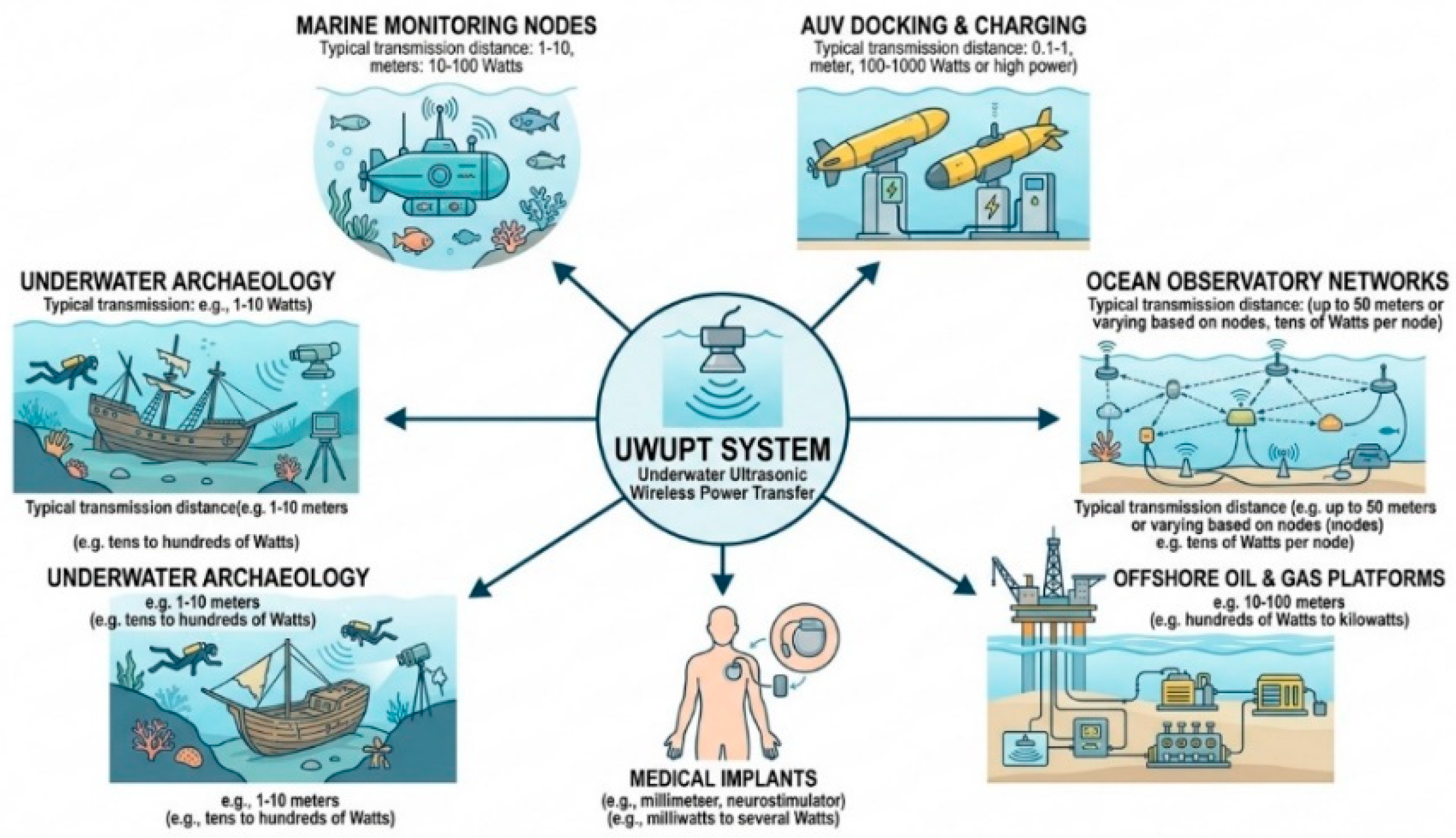
Underwater ultrasonic wireless power transfer technology shows considerable application potential in many fields. The diverse requirements of these fields are, in turn, driving the rapid evolution of the technology [43]. This mapping reveals the physical constraints imposed by each application scenario. Marine monitoring emphasizes low-power maintenance-free operation over moderate distances. AUV charging demands high-power short-range transfer with precise alignment tolerance. Deep-sea infrastructure requires kilowatt-level delivery through complex metal structures under extreme pressure. The diversified application domains of UUWPT technology are illustrated in Figure 9.
Figure 9.
Diversified application domains of UUWPT technology.
Marine monitoring and environmental observation constitute one of the most important application fields. With the deepening of marine scientific research, the demand for long-term, real-time, large-area marine monitoring is increasing. This is especially true for long-term observation nodes in the deep-sea environment. Traditional battery power supply cannot support continuous operation for months to years, whereas ultrasonic wireless power offers a feasible solution. It is foreseeable that battery-free underwater sensor nodes based on UUWPT will play an important role in large-scale marine monitoring networks [44].
Autonomous underwater vehicles (AUVs) constitute another important application field. They are also one of the main engineering scenarios driving the development of UUWPT. AUVs play an increasingly important role in marine resource exploration, submarine pipeline inspection, military reconnaissance, and other tasks. However, endurance remains the biggest bottleneck limiting their operational radius and mission duration. Studies have shown that underwater wireless power transfer can significantly improve the endurance of AUVs. Even fixed wireless charging stations can be established on the seabed for AUVs to autonomously dock and charge [6].
UUWPT also shows great application potential in the field of marine energy development. Facilities such as offshore wind farms and offshore oil and gas platforms contain a large number of underwater devices requiring continuous power supply. Traditional wired power supply is not only expensive and difficult to maintain but also poses safety risks due to cable breakage. Wireless power supply offers a more flexible and economical alternative for these scenarios. In deep-sea oil and gas development, the power supply of underwater production systems has always been a technical challenge. UUWPT is expected to play a unique role in this area [45].
The Internet of Underwater Things (IoUT) represents a future-oriented development direction. Researchers have proposed the concept of battery-free underwater sensor node platforms that use ultrasound for wireless charging. These nodes can perform sensing operations and ultrasonic communication [25]. This technology provides basic support for building large-scale, distributed marine monitoring networks. It is expected to become one of the key technologies for the IoUT [15].
UUWPT technology is also expanding into other fields. Research on ultrasonic power transfer for medical implants can inform UUWPT design [23]. In cultural heritage protection and underwater archaeology, wireless power can provide continuous electricity for long-term monitoring equipment. In the military field, the concealment and autonomy of underwater equipment are crucial. Wireless power supply helps reduce dependence on logistics support and improves equipment survivability and combat effectiveness.
Table 6 summarizes the main application fields in terms of transmission distance, power level, and technical difficulties.
Table 6.
Main application fields of UUWPT and their requirement characteristics.
4.3. Future Research Roadmap
Based on the technical bottlenecks and engineering challenges discussed above, the future development of UUWPT should move from isolated single-point demonstrations toward standardized, adaptive, and application-driven engineering systems. The following roadmap outlines a phased approach to guide research and deployment efforts over the coming years, as summarized in Table 7. This three-stage framework is defined according to the current maturity of key technologies, the urgency of industrial demands, and the time required for field validation in real marine environments.
Table 7.
Proposed roadmap for UUWPT research and engineering deployment.
5. Existing Problems and Challenges
5.1. Technical Bottlenecks
Although underwater ultrasonic wireless power transfer technology has made remarkable progress, it still faces many challenges at the technical level.
The contradiction between transmission efficiency and transmission distance is the core trade-off of UUWPT. As the transmission distance increases, the ultrasound wave propagating in water is affected by geometric spreading, absorption attenuation, and scattering. These effects lead to a rapid decrease in the available power at the receiver [46]. Although low-frequency acoustic waves can reduce propagation loss, they have longer wavelengths and require larger transducers to achieve good directivity. This is detrimental to system miniaturization. Current research generally indicates that high-efficiency transmission is usually easier to achieve over short distances. When the distance extends beyond 10 m, without array focusing, frequency optimization, and matching compensation, the efficiency drops significantly. However, the development of MISO/MIMO technology is expected to alleviate this problem. In comparison, electromagnetic array WPT systems have achieved DC–DC efficiencies of 74–84% with optimized coil overlap designs and phase control strategies [29]. Capacitive coupling systems have demonstrated 94.5% efficiency at 20 mm distance in seawater [4]. However, these technologies are fundamentally constrained by their near-field nature. They cannot match UUWPT’s meter-scale transmission capability.
Reported high efficiencies should be compared only after normalizing the definition of efficiency, the input and output measurement points, the acoustic aperture, the water path, and the alignment condition. For example, a meter-scale efficiency value obtained in a tank with coaxially aligned transducers is not equivalent to an open-sea link with moving platforms and reflecting boundaries. Similarly, high-power deep-sea demonstrations such as kilowatt-level SWPDT validate pressure-tolerant integration and engineering robustness. However, they are usually based on constrained coupling geometry, careful thermal design, and dedicated packaging. They should not be interpreted as evidence that long-range free-field UUWPT has already solved the efficiency–distance trade-off [27].
UUWPT also faces the difficulty of frequency selection. The choice of operating frequency requires a trade-off among multiple factors. High frequencies (>100 kHz) have short wavelengths, good directivity, and small transducer sizes, but suffer from large propagation loss in water and limited transmission distance. Low frequencies (20–50 kHz) have small propagation loss and are suitable for long-distance transmission, but require larger transducers and have poorer directivity [14]. Moreover, the frequency selection is also affected by marine environmental noise and bioacoustic interference. Further research is needed to determine the optimal operating frequency for different application scenarios.
Frequency selection is also linked to cavitation and safety. At high acoustic pressure, bubbles can nucleate or oscillate, causing nonlinear loss, acoustic noise, local erosion, and potential damage to coatings or biological targets. The cavitation threshold depends on frequency, ambient pressure, dissolved gas, temperature, and pulse duty cycle. Consequently, high-power UUWPT should report acoustic pressure, duty factor, and safety margin in addition to electrical efficiency [14].
Impedance matching complexity is another difficulty in the engineering implementation of UUWPT. In practical marine applications, the characteristics of the transmission medium (e.g., temperature, salinity, flow velocity) are continuously changing. These variations affect the impedance characteristics of the transducer and thus the matching state of the system. If the position of the receiver changes, the acoustic characteristics of the transmission path also change, requiring re-matching of impedances. Current research mainly focuses on static impedance matching. Further research is needed on adaptive impedance matching technology in dynamic environments [26].
In complex underwater environments, ultrasound encounters various obstacles (such as the seabed, water surface, and reefs). These obstacles produce reflections and scattering, thereby forming multipath propagation. Multipath propagation causes phase differences and amplitude variations. It interferes with the transmission characteristics and severely affects transmission performance. This effect is especially pronounced in short-range transmission. The interference between the direct wave and reflected waves may cause a sharp drop in signal strength at certain positions, creating “dead zones” [47].
In a narrowband UUWPT system, the multipath acoustic channel can be expressed as:
where is the number of propagation paths, is the frequency-dependent amplitude coefficient of the -th path, is the operating frequency, and is the propagation delay of the -th path. Therefore, the received acoustic power can be approximately expressed as:
where is the transmitted acoustic power. When the phase difference between two propagation paths satisfies:
where is an integer, destructive interference occurs, resulting in local power fading or acoustic “dead zones.” To mitigate this problem, frequency optimization, array-based phase control, time-reversal focusing, receiver diversity, and adaptive impedance matching can be adopted to improve the stability of energy transfer in complex underwater environments.
5.2. Engineering Challenges and Environmental Adaptability
In terms of engineering application and environmental adaptability, underwater ultrasonic wireless power transfer technology also faces many practical difficulties.
The complexity of the marine environment is one of the biggest challenges in engineering. Parameters such as temperature, salinity, pressure, flow velocity, and water quality vary with depth, location, and time. These variations directly affect the propagation characteristics of ultrasound. For example, a temperature change of 1 °C changes the sound speed by about 4–5 m/s. A salinity change of 1‰ changes the sound speed by about 1.4–1.5 m/s. A pressure increase of 1 atmosphere (about 10 m water depth) changes the sound speed by about 0.17 m/s [48]. These parameter changes cause refraction and scattering of sound waves, affecting the efficiency and stability of energy transmission. In addition, equipment working in seawater for long periods faces serious biofouling problems. Marine organisms (e.g., barnacles and algae) attach to the transducer surface, altering its acoustic characteristics and reducing transmission efficiency [49]. At the same time, the corrosiveness of seawater causes electrochemical corrosion of metal parts, affecting system reliability and lifetime. Current solutions mainly include antifouling coatings and regular maintenance, but each has limitations. Antifouling coatings may affect the acoustic performance of the transducer, whereas regular maintenance increases cost and risk [50].
Underwater ultrasonic wireless power transfer systems usually need to be integrated with other systems (e.g., communication systems, control systems, and energy management systems). System integration faces many problems, such as interface standardization, electromagnetic compatibility, and signal interference. This is particularly challenging in multi-device collaborative scenarios. In such cases, avoiding mutual interference between different devices and achieving coordinated system operation is a complex issue in engineering applications [7].
Although the manufacturing cost of ultrasonic transducers is relatively low, the overall cost of achieving a high-performance UUWPT system is still high. The main costs include high-performance piezoelectric materials, precision machining, system integration and testing, and maintenance. This is especially problematic in large-scale application scenarios. Reducing the unit cost and improving the cost-effectiveness remain important challenges for industrialization, as detailed in Table 8.
Table 8.
Structured techno-economic considerations for UUWPT engineering deployment.
6. Conclusions
In summary, underwater ultrasonic wireless power transfer technology provides a promising solution to the continuous power supply problem of underwater equipment. Significant progress has been made in theoretical modeling, system design, array-based power transfer, and simultaneous power and data transfer. This demonstrates considerable potential for engineering applications. Compared with traditional wired power supply and other underwater wireless power transfer methods, UUWPT offers unique advantages in contactless power delivery, environmental adaptability, and medium-to-long-distance transmission. Together with emerging UCPT and LPT technologies, UUWPT contributes to a comprehensive underwater wireless power supply ecosystem. In this ecosystem, different technologies can be selected based on specific application requirements regarding transmission distance, power level, environmental conditions, and data rate demands.
The comparative tables and roadmap presented herein further indicate that UUWPT should not be evaluated only by peak efficiency. A fair assessment must also include operating frequency, aperture, pressure level, distance, alignment tolerance, data-link coexistence, and life-cycle cost.
Currently, the technology is at a critical stage transitioning from experimental validation to large-scale application. Key issues remain unresolved, including the trade-off between transmission efficiency and distance, stability and reliability in complex marine environments, and system integration challenges. Future research should further strengthen efforts in high-performance transducer and array structure design, intelligent adaptive impedance matching, simultaneous power and data transfer, and long-term deep-sea operation validation. These efforts will promote UUWPT toward high efficiency, long distance, strong robustness, and engineering practicality. With the continuous integration of multiple disciplines such as materials science, control engineering, acoustics, and marine engineering, underwater ultrasonic wireless power transfer is expected to become a key supporting technology for the next-generation energy security system of marine equipment.
Author Contributions
Y.W. was responsible for the conceptualization, investigation, and writing of the original draft; W.L. was responsible for the formal analysis, writing of the original draft, and writing—review and editing; Q.D. was responsible for the supervision, validation, and project administration. All authors have read and agreed to the published version of the manuscript.
Funding
This work was supported by the National Natural Science Foundation of China under Grant 52577012.
Data Availability Statement
Data sharing is not applicable to this article, as no new data were created or analyzed in this study.
Conflicts of Interest
The authors declare no conflicts of interest.
References
- Orekan, T.; Zhang, P. Underwater Wireless Power Transfer: Smart Ocean Energy Converters; Springer: Cham, Switzerland, 2019. [Google Scholar]
- Hayslett, T.M.; Orekan, T.; Zhang, P. Underwater wireless power transfer for ocean system applications. In Proceedings of the OCEANS 2016 MTS/IEEE Monterey, Monterey, CA, USA, 1 December 2016; pp. 1–6. [Google Scholar] [CrossRef] [Scilit]
- Wu, X.S.; Sun, P.; Yang, S.Q.; He, L.; Cai, J. Review of underwater wireless power transmission technology and its applications. Trans. China Electrotech. Soc. 2019, 34, 1559–1568. [Google Scholar]
- Liu, Y.; Li, B.; Pan, L.; Yao, S.; Dong, Z.; Zhang, J.; Zhu, C.; Cui, S. Review on Development and Research of Underwater Capacitive Power Transfer. Energies 2024, 17, 6496. [Google Scholar] [CrossRef] [Scilit]
- Palitharathna, K.W.S.; Suraweera, H.A.; Godaliyadda, R.I.; Herath, V.R.; Ding, Z. Lightwave Power Transfer in Full-Duplex NOMA Underwater Optical Wireless Communication Systems. IEEE Commun. Lett. 2022, 26, 622–626. [Google Scholar] [CrossRef] [Scilit]
- Wang, D.; Zhang, J.; Cui, S.; Bie, Z.; Chen, F.; Zhu, C. The state-of-the-arts of underwater wireless power transfer: A comprehensive review and new perspectives. Renew. Sustain. Energy Rev. 2024, 189, 113910. [Google Scholar] [CrossRef] [Scilit]
- Teeneti, C.R.; Truscott, T.T.; Beal, D.N.; Pantic, Z. Review of wireless charging systems for autonomous underwater vehicles. IEEE J. Ocean. Eng. 2021, 46, 68–87. [Google Scholar]
- Feng, Y.; Sun, Y.; Lin, T.; Hu, H.; Chen, F. Mutual inductance surrogate model of the UWPT system and its constant power optimization at misaligned positions. Wirel. Power Transf. 2024, 11, e001. [Google Scholar] [CrossRef] [Scilit]
- Chen, X.Y.; Xu, K.; Mou, X.M.; Li, G. Comparison of inductive coupling and ultrasonic coupling wireless power transfer technology in seawater. Electr. Mach. Control 2018, 22, 9–16. [Google Scholar]
- Guida, R.; Demirors, E.; Dave, N.; Melodia, T. Underwater ultrasonic wireless power transfer: A battery-less platform for the internet of underwater things. IEEE Trans. Mob. Comput. 2022, 21, 1861–1873. [Google Scholar]
- Shahab, S.; Erturk, A. Contactless ultrasonic energy transfer for wireless systems: Acoustic-piezoelectric structure interaction modeling and performance enhancement. Smart Mater. Struct. 2014, 23, 125032. [Google Scholar] [CrossRef] [Scilit]
- Liao, C.; Zhang, H.; Li, Z.; Zhang, Q. Simulation and experiment of a medium-distance underwater ultrasonic wireless power transfer system. Arch. Acoust. 2025, 50, 3. [Google Scholar] [CrossRef] [Scilit]
- Liu, Z.; Zhang, T.; Li, Y.; Yuan, Y.; Mahmud, N.; Geng, Y. Dynamic frequency optimization for underwater acoustic energy transmission: Balancing absorption and geometric diffusion in marine environments. J. Mar. Sci. Eng. 2025, 13, 1089. [Google Scholar] [CrossRef] [Scilit]
- Li, Y.; Zhang, T.; Liu, Z.; Mahmud, N.; Geng, Y. A frequency optimization method considering acoustic cavitation for maximizing received power in underwater wireless ultrasonic power transfer systems. J. Mar. Sci. Eng. 2025, 13, 2023. [Google Scholar] [CrossRef] [Scilit]
- Nordfjord, S.J.; Thorsteinsson, S.E.; Andersen, K. Powering underwater robotics sensor networks through ocean energy harvesting and wireless power transfer methods: Systematic review. J. Mar. Sci. Eng. 2025, 13, 1728. [Google Scholar] [CrossRef] [Scilit]
- Zou, Y.W.; Huang, X.L.; Bai, Y. Non-contact energy transfer based on ultrasonic. Adv. Mater. Res. 2011, 308–310, 1341–1344. [Google Scholar] [CrossRef] [Scilit]
- Kinsler, L.E.; Frey, A.R.; Coppens, A.B.; Sanders, J.V. Fundamentals of Acoustics, 4th ed.; Wiley: New York, NY, USA, 2000. [Google Scholar]
- Arnau, A. (Ed.) Piezoelectric Transducers and Applications, 2nd ed.; Springer: Berlin, Germany, 2008. [Google Scholar]
- Sherrit, S.; Leary, S.P.; Dolgin, B.P.; Bar-Cohen, Y. Comparison of the Mason and KLM Equivalent Circuits for Piezoelectric Resonators in the Thickness Mode. In Proceedings of the 1999 IEEE Ultrasonics Symposium, Lake Tahoe, NV, USA, 17–20 October 1999; pp. 921–926. [Google Scholar]
- Leedom, D.A.; Krimholtz, R.; Matthaei, G.L. Equivalent circuits for transducers having arbitrary even- or odd-symmetry piezoelectric excitation. IEEE Trans. Sonics Ultrason. 1971, 18, 128–141. [Google Scholar] [CrossRef]
- Roes, M.G.L.; Duarte, J.L.; Hendrix, M.A.M.; Lomonova, E.A. Acoustic energy transfer: A review. IEEE Trans. Ind. Electron. 2013, 60, 242–248. [Google Scholar] [CrossRef] [Scilit]
- Ozeri, S.; Shmilovitz, D. Ultrasonic transcutaneous energy transfer using a continuous wave 650 kHz Gaussian shaded transmitter. Ultrasonics 2010, 50, 666–674. [Google Scholar] [CrossRef] [Scilit] [PubMed]
- Basaeri, H.; Christensen, D.B.; Roundy, S. A review of acoustic power transfer for bio-medical implants. Smart Mater. Struct. 2016, 25, 123001. [Google Scholar] [CrossRef] [Scilit]
- Wang, D.A.; Zhang, J.T.; Zhu, C.B.; Bie, Z.; Cui, S.M. Research progress on the influence mechanism of marine environment on underwater wireless power transfer systems. Trans. China Electrotech. Soc. 2025, 40, 653–675. [Google Scholar] [CrossRef] [Scilit]
- Guida, R.; Demirors, E.; Dave, N.; Rodowicz, J.; Melodia, T. An acoustically powered battery-less internet of underwater things platform. In Proceedings of the 2018 Fourth Underwater Communications and Networking Conference (UComms); IEEE: Piscataway, NJ, USA, 2018. [Google Scholar]
- Xu, K.; Chen, X.Y.; Liu, D.N. Electrical impedance transformation technology for underwater ultrasonic coupled wireless power transfer system. Proc. CSEE 2015, 35, 4461–4465. [Google Scholar]
- Da, C.; Li, F.; Li, S.; Gong, L.; Li, X.; Tao, C.; Wang, L. Engineering simultaneous 4 kW wireless power and full-duplex data transfer system for 4000-meter deep-sea applications. IEEE Trans. Ind. Electron. 2025, 73, 5420–5431. [Google Scholar] [CrossRef] [Scilit]
- Shen, S.; Clerckx, B. Beamforming optimization for MIMO wireless power transfer with nonlinear energy harvesting: RF combining versus DC combining. IEEE Trans. Wirel. Commun. 2021, 20, 199–213. [Google Scholar] [CrossRef] [Scilit]
- Kang, N.; Qin, H.; Ma, R.; Lee, C.H.T.; Liu, M.; Ma, C. Magnetic Field Projection and Current Phase Control in a 2-D Planar Transmitting Coil Array. IEEE Trans. Power Electron. 2024, 39, 10623–10637. [Google Scholar] [CrossRef] [Scilit]
- Pahlavan, S.; Shooshtari, M.; Maleki, M.; Jafarabadi Ashtiani, S. Using Overlapped Resonators in Wireless Power Transfer for Uniform Electromagnetic Field and Removing Blank Spots in Free Moving Applications. Electronics 2022, 11, 1204. [Google Scholar] [CrossRef] [Scilit]
- Mohsan, S.A.H.; Khan, M.A.; Mazinani, A.; Alsharif, M.H.; Cho, H.S. Enabling underwater wireless power transfer towards sixth generation (6G) wireless networks: Opportunities, recent advances and technical challenges. J. Mar. Sci. Eng. 2022, 10, 1282. [Google Scholar] [CrossRef] [Scilit]
- Martinez de Alegria, I.; Rozas Holgado, I.; Ibarra, E.; Robles, E.; Martin, J.L. Wireless power transfer for unmanned underwater vehicles: Technologies, challenges and applications. Energies 2024, 17, 2305. [Google Scholar] [CrossRef] [Scilit]
- Freychet, O.; Frassati, F.; Boisseau, S.; Brulais, S.; Despesse, G. Multiple input single output configurations to improve performances and robustness of acoustic power transfer. Ultrasonics 2021, 116, 106524. [Google Scholar] [CrossRef] [Scilit] [PubMed]
- Kashani, Z.; Ilham, S.J.; Kiani, M. Design and optimization of ultrasonic links with phased arrays for wireless power transmission to biomedical implants. IEEE Trans. Biomed. Circuits Syst. 2022, 16, 64–78. [Google Scholar] [CrossRef] [Scilit] [PubMed]
- Liu, Z.; Zhang, T.; Yuan, Y.; Li, Y.; Geng, Y. Evaluation method for underwater ultrasonic energy radiation performance based on the spatial distribution characteristics of acoustic power. Sensors 2024, 24, 3942. [Google Scholar] [CrossRef] [Scilit] [PubMed]
- Zhang, Q.; Wang, Y.F. Contactless power and data transmission for ocean buoys. Chin. J. Sci. Instrum. 2010, 31, 2615–2621. [Google Scholar]
- Yao, Y.; Sun, P.; Liu, X.; Wang, Y.; Xu, D. Simultaneous wireless power and data transfer: A comprehensive review. IEEE Trans. Power Electron. 2022, 37, 3650–3667. [Google Scholar] [CrossRef] [Scilit]
- Esmaiel, H.; Qasem, Z.A.H.; Sun, H.; Qi, J.; Wang, J.; Gu, Y. Wireless information and power transfer for underwater acoustic time-reversed NOMA. IET Commun. 2020, 14, 3394–3403. [Google Scholar] [CrossRef] [Scilit]
- Luo, Y.; Yang, Y.; Hong, H.; Dai, Z. A simultaneous wireless power and data transfer system with full-duplex mode for underwater wireless sensor networks. IEEE Sens. J. 2024, 24, 12570–12583. [Google Scholar] [CrossRef] [Scilit]
- Li, T.; Sun, Z.; Wang, Y.; Mai, J.; Xu, D. Undersea simultaneous wireless power and data transfer system with extended communication distance and high rate. IEEE Trans. Power Electron. 2024, 39, 2917–2921. [Google Scholar] [CrossRef] [Scilit]
- Yang, L.; Xing, D.; Wen, H.; Zhao, Y.; Yang, T.; Sun, Y.; Zhang, A.; Tong, X. High power density integrated wireless power transfer method for underwater intelligent sensors. Wirel. Power Transf. 2026, 13, e008. [Google Scholar] [CrossRef] [Scilit]
- Bakhtiari-Nejad, M.; Elnahhas, A.; Hajj, M.R.; Shahab, S. Acoustic holograms in contactless ultrasonic power transfer systems: Modeling and experiment. J. Appl. Phys. 2018, 124, 244901. [Google Scholar] [CrossRef] [Scilit]
- Gao, J.X.; Wu, X.S.; Gao, K.; Li, G.Y. Review of contactless power transfer technology based on electromagnetic induction. J. Power Supply 2017, 15, 166–178. [Google Scholar]
- Heidemann, J.; Stojanovic, M.; Zorzi, M. Underwater sensor networks: Applications, advances and challenges. Philos. Trans. R. Soc. A 2012, 370, 158–175. [Google Scholar] [CrossRef] [Scilit]
- Kaur, N.; Sudhakar, K.; Mohamed, M.R.; Cuce, E.; Barbulescu, D. Wireless power transfer in offshore renewable energy: A review of technologies, challenges, and future directions. Unconv. Resour. 2026, 9, 100287. [Google Scholar] [CrossRef] [Scilit]
- Stojanovic, M.; Preisig, J. Underwater acoustic communication channels: Propagation models and statistical characterization. IEEE Commun. Mag. 2009, 47, 84–89. [Google Scholar] [CrossRef] [Scilit]
- van Walree, P.A. Propagation and scattering effects in underwater acoustic communication channels. IEEE J. Ocean. Eng. 2013, 38, 614–631. [Google Scholar] [CrossRef] [Scilit]
- Mackenzie, K.V. Nine-term equation for sound speed in the oceans. J. Acoust. Soc. Am. 1981, 70, 807–812. [Google Scholar] [CrossRef] [Scilit]
- Callow, M.E.; Callow, J.A. Marine biofouling: A sticky problem. Biologist 2002, 49, 10–14. [Google Scholar] [PubMed]
- Callow, J.A.; Callow, M.E. Trends in the development of environmentally friendly fouling-resistant marine coatings. Nat. Commun. 2011, 2, 244. [Google Scholar] [CrossRef] [Scilit] [PubMed]

Disclaimer/Publisher’s Note: The statements, opinions and data contained in all publications are solely those of the individual author(s) and contributor(s) and not of MDPI and/or the editor(s). MDPI and/or the editor(s) disclaim responsibility for any injury to people or property resulting from any ideas, methods, instructions or products referred to in the content. |
© 2026 by the authors. Licensee MDPI, Basel, Switzerland. This article is an open access article distributed under the terms and conditions of the Creative Commons Attribution (CC BY) license.