


Abstract
Simultaneous transmit-and-receive (STAR) antennas are important components of in-band full-duplex wireless front ends. However, transmit-to-receive leakage through the antenna limits the achievable antenna-domain isolation. This paper presents a dual-circularly polarized patch antenna incorporating a decoupling feeding network (DFN) to suppress the residual coupling between the transmit and receive ports. A stacked patch radiator with cross-aperture coupling generates right-hand and left-hand circularly polarized radiation from two separate ports. The DFN introduces an additional coupling path whose magnitude and electrical phase are adjusted to produce destructive interference near the target frequency. The fabricated prototype exhibits overlapping −10 dB impedance and 3 dB axial ratio bandwidths from 4.1 to 4.4 GHz, a minimum measured S21 of −50 dB, isolation higher than 30 dB from 4.25 to 4.28 GHz, and a peak realized gain of 7 dBic. The measured high-isolation range has an absolute bandwidth of 30 MHz and a fractional bandwidth of approximately 0.70% around 4.265 GHz. Therefore, the proposed DFN provides narrowband antenna-domain isolation enhancement around the designed frequency without requiring additional patterned decoupling elements on the radiating aperture. The proposed antenna is primarily intended for fixed-frequency or narrow-channel STAR front ends rather than broadband high-isolation operation.
1. Introduction
Simultaneous transmit and receive (STAR), also known as in-band full-duplex (IBFD) operation, enables a wireless node to transmit and receive over the same time–frequency resources [1,2]. This technique has been investigated for wireless communication, radar, and integrated sensing and communication systems [3,4]. A major challenge in STAR front ends is self-interference (SI), in which the transmitted signal leaks into the receiving channel through antenna coupling, RF-chain leakage, and environmental reflections. Since the leakage signal can be much stronger than the desired received signal, insufficient suppression before the receiver chain may reduce the available dynamic range and degrade receiver performance. Therefore, improving the isolation between the transmit and receive ports is an important issue in STAR antenna design.
The isolation achieved by antenna design should be distinguished from system-level SI cancelation. Antenna isolation mainly reduces the leakage coupled from the transmit port to the receive port before the signal enters the receiver chain. It does not suppress RF-chain leakage, transmitter nonlinear distortion, phase noise, or environmental multipath echoes. Therefore, this work focuses on passive transmit–receive isolation enhancement in a dual-circularly polarized (DCP) patch antenna rather than on complete system-level SI cancelation.
Circularly polarized (CP) antennas reduce sensitivity to polarization mismatch and multipath-induced polarization rotation [5,6]. Extending this concept, DCP antennas that employ right-hand circular polarization (RHCP) and left-hand circular polarization (LHCP) for separate transmit and receive channels offer additional potential for polarization multiplexing [6]. However, DCP antennas are particularly sensitive to amplitude and phase imbalances in their feeding networks. Improving port isolation therefore requires more than simply reducing the transmission coefficient between the transmit and receive ports; it must also preserve the orthogonal amplitude–phase relationship required for circularly polarized radiation. Any decoupling structure that introduces uncontrolled amplitude or phase perturbations can degrade the AR, increase cross-polarization, or reduce the main-beam gain [6,7].
Thus, for DCP STAR front-end antennas, an important challenge is to enhance transmit–receive isolation without degrading the AR, cross-polarization level, or realized gain [8,9,10].
Existing isolation-enhancement methods for STAR antennas can be broadly divided into decoupling feeding networks (DFNs) and decoupling spatial structures (DSSs). DSS-based methods usually employ parasitic elements, defected ground structures, cavities, modal control, feeding rearrangement, weak-field self-decoupling, or aperture-level field manipulation to reduce coupling between antenna ports [11,12,13,14]. These methods can improve isolation, but they often require additional structures near the radiating aperture or modifications to the radiator geometry. Such structural loading may increase the difficulty of maintaining stable DCP radiation performance, especially when impedance matching, AR, gain, and array scalability are considered simultaneously.
In contrast, DFN-based methods improve isolation by introducing an additional coupling path through the feeding network. By controlling the coupling coefficient and electrical length of the network, the signal coupled through the DFN can be adjusted to cancel the direct coupling component at the receive port. Since the decoupling structure is implemented in the feeding network, the radiating aperture can be kept unchanged. This feature is useful for DCP patch antennas because the stacked patch radiator can be designed for RHCP/LHCP radiation, while the DFN is used to reduce the residual coupling between the two ports.
Amplitude and phase control using feeding networks has been shown to improve transmit–receive isolation in full-duplex patch antennas. Nawaz and Tekin reported a differentially fed microstrip patch antenna that used a 180° ring hybrid to enhance port isolation. Their single-layer design achieved more than 67 dB transmit–receive isolation at 2.4 GHz, while a slot-coupled transmit port combined with a differential receive configuration further increased the isolation to above 90 dB at 2.41 GHz. The same single-layer structure maintained more than 62 dB isolation over a 50 MHz bandwidth defined by a 10 dB return-loss criterion [15]. These results indicate that feeding-network-based amplitude and phase control can reduce transmit–receive coupling in full-duplex antennas. Nevertheless, such designs are based on differentially fed, orthogonal, linearly polarized patch structures. Because their isolation mechanism relies on 180° differential-mode excitation and the symmetry of linearly polarized ports, these designs are not directly applicable to LHCP/RHCP DCP patch antennas. For DCP antennas, the feeding network must suppress coupling between the ports while simultaneously preserving the amplitude and phase balance of two orthogonal circularly polarized modes; otherwise, axial ratio (AR) degradation and polarization-purity deterioration may occur. Related differential-feeding and traveling-wave-array implementations have further demonstrated that controlled amplitude–phase cancelation is an effective route for transmit–receive isolation enhancement in full-duplex antennas [2,16].
For circularly polarized arrays, Wang and Wu proposed a DFN based on orthogonal-mode decomposition. Their method established a network model for the complex coupling paths in a dual-fed circularly polarized patch array and was validated using a 2 × 2 circularly polarized patch array. After applying the DFN, the mutual coupling between array ports was reduced to below −33 dB at the 1.26 GHz center frequency, corresponding to a decoupling improvement of 15–23 dB, while maintaining a realized gain of approximately 9.4 dBi [17]. This study confirms that DFNs can regulate coupling in circularly polarized arrays. However, its target problem is mainly mutual coupling between array elements rather than transmit–receive isolation between circularly polarized ports within the same STAR front end. These two cases involve different coupling paths and design constraints.
More recently, circularly polarized and dual-circularly polarized STAR/IBFD antennas have been investigated using co-circularly polarized shared apertures, sequentially rotated arrays, hierarchical decoupling, and parasitic-element-assisted isolation enhancement [12,13,14,18,19,20,21]. Wu et al. reported a compact monostatic co-circularly polarized STAR antenna with high isolation [19]. Fu et al. further demonstrated a DCP STAR antenna array with high realized gain and enhanced isolation [20]. Xie et al. developed a DCP monostatic STAR antenna consisting of a sequentially rotated array, two beamforming networks, and a hybrid decoupling structure combining a uniplanar compact electromagnetic bandgap structure with an annular defected ground structure. The antenna achieved more than 33 dB transmit–receive isolation from 4.25 to 4.35 GHz while maintaining a voltage standing wave ratio below 2 and an AR below 3 dB [13]. This design used RHCP transmission and LHCP reception, but its decoupling performance relied on array rotation, EBG/DGS loading, and structural manipulation near the radiating aperture. Dao-Duc et al. proposed a compact shared-aperture dual-sense circularly polarized STAR antenna with a measured operating bandwidth of 1.6% from 2.45 to 2.49 GHz, a maximum in-band isolation of 39 dB, and a peak gain of 5.7 dBi [21]. Although this design emphasized compactness, its operating bandwidth remained relatively narrow. Wang et al. further introduced a hierarchical decoupling strategy that reduced transmit–receive coupling in a DCP antenna through feeding rearrangement and weak-field self-decoupling. Their prototype achieved measured transmit–receive isolation higher than 20 dB from 4.35 to 4.75 GHz, with a maximum isolation of 44 dB [14]. More recently, Tran-Huy et al. proposed a wideband, high-isolation DCP co-aperture antenna using non-uniform parasitic elements, further highlighting the role of aperture-level and parasitic-element-assisted isolation control in DCP antennas [12]. These studies show that high isolation can be achieved in CP and DCP STAR antennas. However, many reported designs rely on aperture loading, sequential array rotation, EBG/DGS structures, feeding rearrangement, or radiator-level modification. For a planar DCP patch antenna, it is desirable to improve transmit–receive isolation without loading additional decoupling structures near the radiating aperture. Such a design strategy can help preserve the CP radiation performance of the stacked patch radiator and simplify subsequent array extension.
Beyond STAR-specific designs, recent antenna studies have also demonstrated that polarization-selective metasurface integration and radiator-edge engineering can provide additional degrees of freedom for multifunctional and compact antenna systems. Wang et al. developed a 3-D-printed pentahedral polarization-division transmissive metadevice capable of manipulating multiple linearly and circularly polarized wavefront channels [22]. Zou et al. proposed a miniaturized low-profile ultrawideband antipodal Vivaldi antenna array using edge-overlap and shorting techniques to extend the low-frequency operating range and improve the performance of the finite array [23]. Although these studies do not directly address transmit–receive isolation in DCP STAR antennas, they illustrate the broader trend of employing spatially loaded and structurally engineered apertures to enhance antenna functionality. In contrast, the present work focuses on a feeding-network-based cancelation approach that preserves the original stacked patch radiating aperture.
To address the above issues, this work applies an inverse-cancelation DFN to a single dual-circularly polarized stacked patch antenna for STAR operation. In contrast to previously reported differential linearly polarized antennas and circularly polarized arrays using feeding-network-based decoupling, the present design suppresses coupling between the RHCP and LHCP ports of the same stacked patch radiator. The general principle of amplitude–phase cancelation is not claimed as new. The contribution of this work lies in its implementation and integration with a dual-sense circularly polarized STAR radiator while avoiding additional patterned decoupling elements, such as EBG, DGS, or parasitic elements, on or immediately adjacent to the radiating aperture. The DFN and the practical cavity-backed integration environment are jointly considered because the cancelation response depends on the electromagnetic boundary condition of the complete antenna assembly.
The main contributions are summarized as follows. First, an inverse-cancelation DFN composed of two parallel-coupled-line sections and two microstrip transmission paths is integrated with the two opposite-sense circularly polarized ports of a single stacked patch antenna. Second, the coupling magnitude and phase-control parameters of the DFN are investigated to clarify their respective effects on the depth and frequency position of the isolation null. Third, the antenna is fabricated and experimentally evaluated under the practical cavity-backed integration condition. The measured results show overlapping impedance and axial ratio bandwidths of 4.1–4.4 GHz, a minimum S21 of −50 dB, a measured >30 dB isolation band of 4.25–4.28 GHz, and a peak realized gain of 7 dBic. The proposed design therefore emphasizes deep isolation near a selected operating frequency rather than broadband isolation or antenna miniaturization.
2. Antenna Design and Performance Analysis
2.1. Antenna Configuration and Integration Model
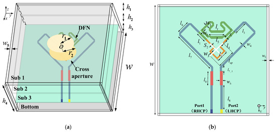
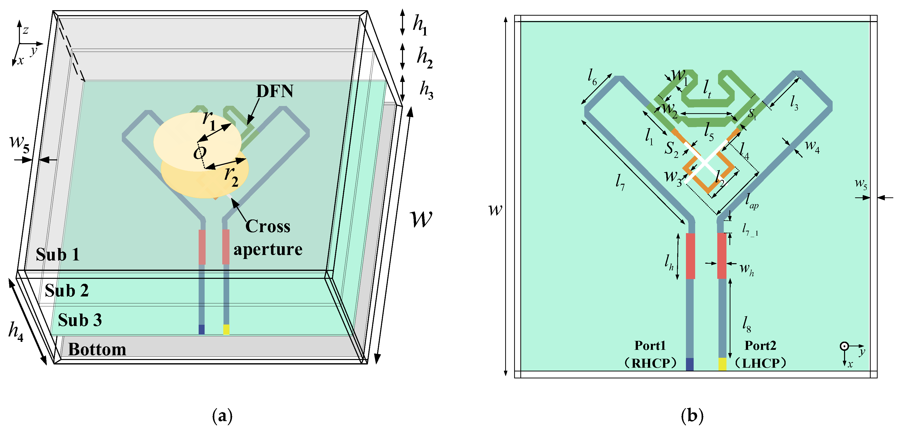
Figure 1 shows the configuration of the proposed high-isolation DCP patch antenna. The antenna consists of a stacked patch radiator, a cross-shaped aperture, and a DFN. Two circular radiating patches with radii of r1 and r2 are printed on the upper surfaces of Substrate 1 and Substrate 2, respectively. Both substrates are FR4 laminates with a thickness of 1 mm. Substrate 3 is a Taconic TLX substrate with a relative permittivity of 2.55 and a thickness of 1 mm. The cross-shaped aperture is etched on the top surface of Substrate 3, whereas the DFN is implemented on the bottom surface of Substrate 3. Two air gaps with heights h1 and h2 are introduced between adjacent substrates to improve the impedance and axial ratio responses.
Figure 1.
Configuration of the proposed DCP STAR antenna and its cavity-backed integration model: (a) three-dimensional antenna and cavity-backed assembly; (b) top view of the cross-shaped aperture, feeding paths, and DFN.
A quarter-wavelength series microstrip feed line is placed near the cross-shaped aperture to excite two orthogonal modes with the required quadrature phase relationship. Port 1 excites RHCP, whereas Port 2 excites LHCP. The stacked radiator and the cross-aperture coupling structure are used to generate the two orthogonal circularly polarized radiation states, while the DFN is used to suppress the residual coupling between the transmit and receive ports.
In the fabricated prototype, the antenna is installed in a cavity-backed supporting structure, and this practical integration environment is included in the final full-wave model. As indicated in Figure 1a, h3 and h4 describe the vertical dimensions associated with the cavity-backed support, whereas w5 denotes the cavity-wall thickness. The bottom conducting plate and the surrounding cavity modify the electromagnetic boundary conditions of the multilayer radiator and may consequently affect the input matching, AR, radiation pattern, direct interport coupling, and frequency position of the isolation null. The cavity is therefore not treated merely as a mechanical holder. To distinguish the effects of the DFN from those of the integration boundary, four simulation cases with and without the DFN and the mounting cavity are defined in Table 1. The optimized geometrical parameters used in the final model are listed in Table 2.
Table 1.
Simulation cases used to evaluate the effects of the DFN and mounting cavity.
Table 2.
Optimized antenna parameters.
2.2. Decoupling Mechanism of the DFN
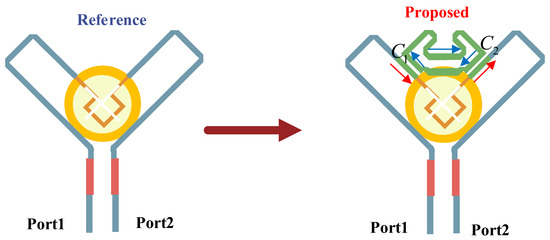
Figure 2 illustrates the design evolution from the reference antenna to the proposed antenna. The reference antenna has the same stacked patch radiator and cross-aperture coupling structure as the proposed antenna, but it does not include the DFN. Owing to the orthogonality between the RHCP and LHCP ports, the reference antenna can provide a certain level of intrinsic port isolation. However, residual transmit–receive coupling still exists within the operating band, which limits the achievable antenna-domain self-interference suppression.
Figure 2.
Design evolution from the reference DCP antenna to the proposed antenna with the DFN.
To further reduce this residual coupling, the DFN is introduced between the two feeding paths. The DFN consists of two microstrip parallel-coupled-line couplers and two microstrip transmission lines. These components form an inverse cancelation loop between Port 1 and Port 2. The basic idea is to introduce an additional coupling component through the feeding network. If this DFN-induced coupling component has a magnitude comparable to that of the direct coupling component and an approximately opposite phase near the target frequency, destructive interference occurs at the receive port, producing a deep isolation null in the S21 response.
The DFN introduces an additional coupling contribution between Port 1 and Port 2. For physical interpretation, the coupling that exists in the reference antenna is denoted by , whereas the coupling contribution associated with the DFN is denoted by . If the two complex contributions have comparable magnitudes and approximately opposite phases near the target frequency, destructive interference occurs at the receive port. The corresponding cancelation condition can be expressed as:
Under this condition, the total complex transmission coefficient is
Here, , , and represent complex linear transmission coefficients rather than logarithmic quantities in decibels. Equations (1) and (2) provide a two-path physical interpretation of the cancelation mechanism. In the complete full-wave antenna model; however, the direct and DFN-associated coupling fields coexist and are not connected to two independent physical observation ports. Consequently, a unique numerical separation of the measured total into and is not claimed in this work.
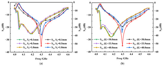
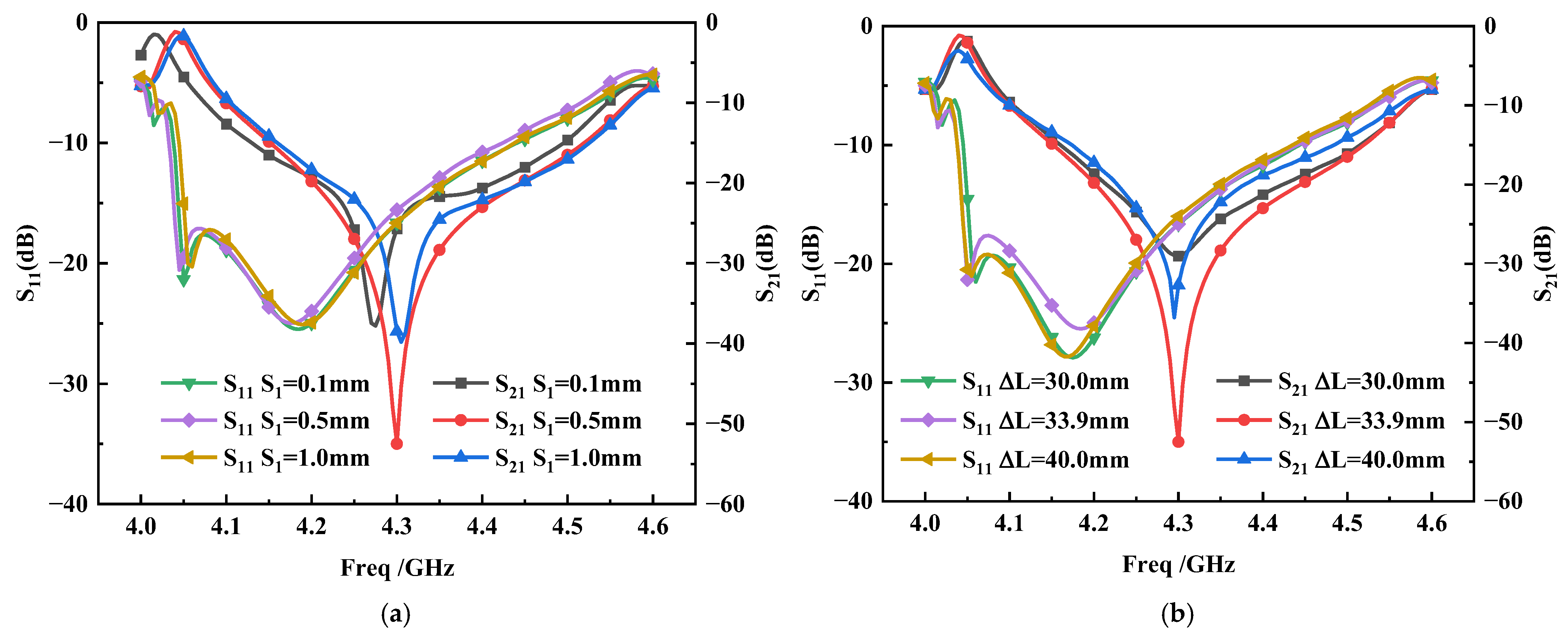
The cancelation interpretation is instead evaluated through complementary parameter trends. The coupled-line spacing mainly controls the magnitude of the coupling introduced by the DFN, whereas the effective phase-control length mainly controls the frequency at which phase opposition occurs. The resulting variations in the depth and frequency position of the null are presented in Figure 3. Because the required magnitude and phase relationship is satisfied only near the designed frequency, the DFN produces a narrowband isolation null rather than broadband isolation enhancement.
Figure 3.
Simulated S11 and S21 responses for different DFN tuning parameters: (a) coupled-line spacing S1; (b) effective DFN phase-control length ΔL.
2.3. DFN Design Guideline and Key Parameters
The DFN is designed using the following procedure. First, the desired high-isolation frequency is selected within the overlapping impedance and axial ratio bandwidth of the reference DCP radiator. In this work, the target frequency is selected near 4.3 GHz.
Second, the reference antenna without the DFN is simulated to determine the residual interport coupling level and the frequency region in which additional cancelation is required. This reference response establishes the total coupling that must be reduced, but no unique numerical decomposition of the coupling into independent physical paths is assumed.
Third, the coupled-line section is adjusted to control the magnitude of the additional coupling introduced by the DFN. The spacing S1 is the main magnitude-control parameter. Reducing S1 generally increases the coupled signal, whereas increasing S1 weakens it. The value of S1 is therefore selected to obtain a sufficiently deep null without significantly degrading , , or the circularly polarized radiation response.
Fourth, the effective DFN phase-control length, denoted by , is adjusted to control the electrical phase of the additional coupling contribution. In this work, represents the effective microstrip centerline length used to tune the phase of the DFN path in the full-wave model. Changing alters the frequency at which the two coupling contributions approach phase opposition and therefore shifts the frequency position of the isolation null.
Finally, the radiator, DFN, and cavity-backed integration model are jointly optimized. The optimization objective is to minimize near 4.3 GHz while maintaining and below −10 dB, an axial ratio below 3 dB, and a stable realized gain within the intended operating band. The optimized values used in this work are S1 = 0.5 mm and = 33.9 mm.
Figure 3 presents a parameter-sensitivity study of S1 and . Changing S1 mainly changes the depth of the isolation null. When S1 deviates from 0.5 mm, the null becomes substantially shallower, which is consistent with a deterioration of the required coupling magnitude balance. In contrast, changing primarily shifts the isolation null away from the target frequency or reduces its depth, which is consistent with a change in the relative electrical phase. These complementary trends support the amplitude–phase cancelation interpretation, although the two conceptual coupling contributions are not separately measured. The parameter values in Figure 3 are selected to illustrate the design sensitivity and should not be interpreted as the exact manufacturing-tolerance range of the prototype.
2.4. Effects of the DFN and Mounting Cavity
To distinguish the effects of the DFN and the mounting cavity, the four simulation cases defined in Table 1 are compared. Case 1 is the cavity-free reference antenna without the DFN. Case 2 is the cavity-free antenna with the DFN. Case 3 is the cavity-backed antenna without the DFN. Case 4 is the cavity-backed antenna with the DFN, corresponding to the final practical configuration.
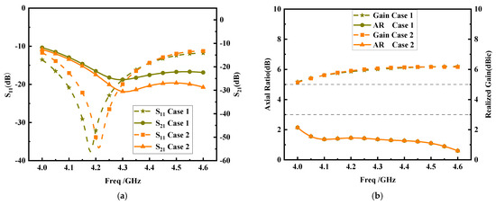
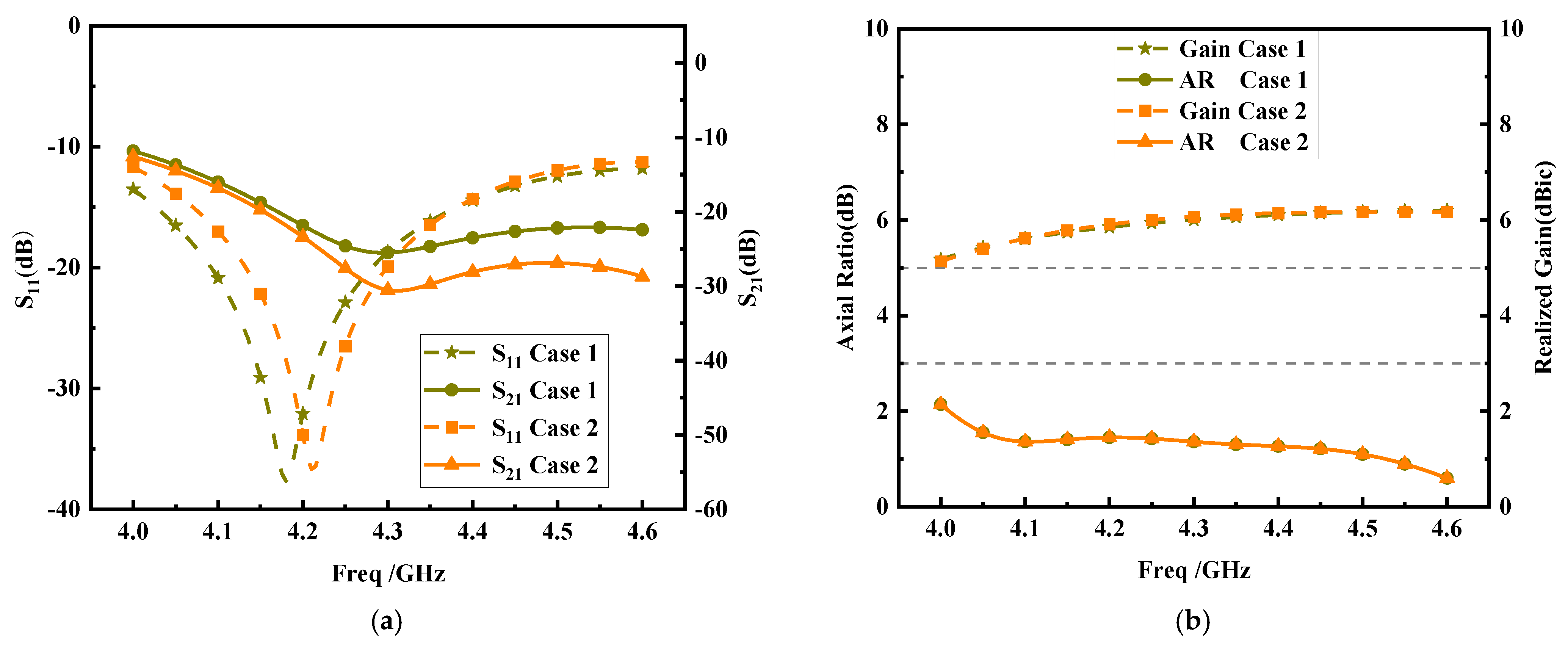
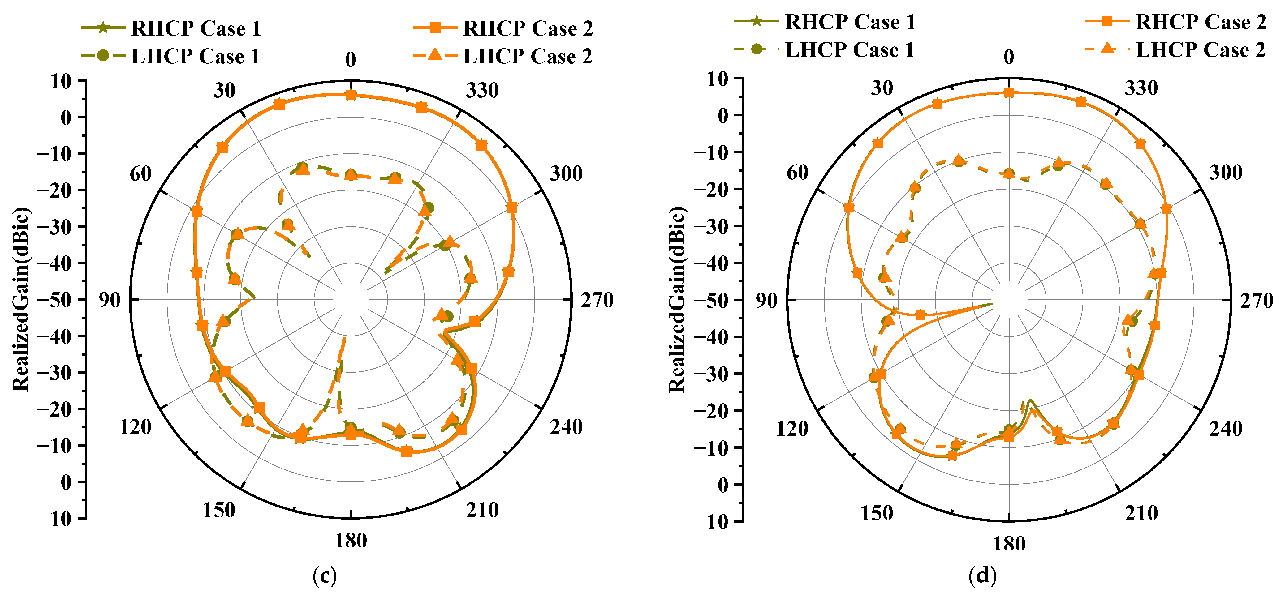
Figure 4 compares Case 1 and Case 2 to evaluate the effect of the DFN under the cavity-free condition. As shown in Figure 4a, the cavity-free reference antenna already provides moderate isolation due to the orthogonality between the RHCP and LHCP ports. At 4.3 GHz, the simulated S21 is −25 dB in Case 1. After the DFN is introduced, S21 is reduced to −30 dB in Case 2, corresponding to an isolation improvement of 5 dB. Therefore, the DFN still introduces an additional cancelation path in the cavity-free model, but the improvement is limited, and no deep isolation null is formed.
Figure 4.
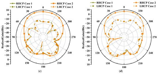
Simulated responses of the cavity-free antenna without and with the DFN: (a) S11 and S21; (b) AR and realized gain; (c) radiation patterns in the xoz plane at 4.3 GHz; (d) radiation patterns in the yoz plane at 4.3 GHz.
This behavior can be explained by the parameter study in Figure 3. As shown in Figure 3a, when the coupled-line spacing S1 is optimized at 0.5 mm, a deep S21 null can be obtained near 4.3 GHz. However, when S1 changes to 0.1 mm or 1.0 mm, the depth of the isolation null is significantly reduced. This indicates that the cancelation effect is highly sensitive to the coupling magnitude introduced by the DFN. Similarly, Figure 3b shows that the optimized effective DFN phase-control length ΔL = 33.9 mm produces the deepest isolation null near the target frequency. When ΔL is changed to 30.0 mm or 40.0 mm, the null shifts away from the target frequency or becomes much shallower, indicating that accurate phase control is also required.
Based on this sensitivity, the limited improvement in Figure 4a can be understood from the change in the electromagnetic integration environment. When the mounting cavity is removed, the electromagnetic boundary conditions and the total interport coupling response of the multilayer antenna are modified. Although the physical dimensions of the DFN remain unchanged, the resulting S21 response is consistent with a deterioration of the amplitude–phase cancelation condition established in the final cavity-backed model. Consequently, the DFN in Case 2 provides only an approximately 5 dB isolation improvement rather than a deep cancelation null.
Figure 4b shows that the axial ratio and realized gain responses of Case 1 and Case 2 remain close to each other within the operating band. The radiation patterns in Figure 4c,d also show no obvious beam distortion after the DFN is introduced. Therefore, the limited isolation improvement in the cavity-free model is not caused by degradation of the CP radiation performance. Instead, it is mainly caused by incomplete amplitude–phase cancelation between the direct coupling path and the DFN-induced coupling path.
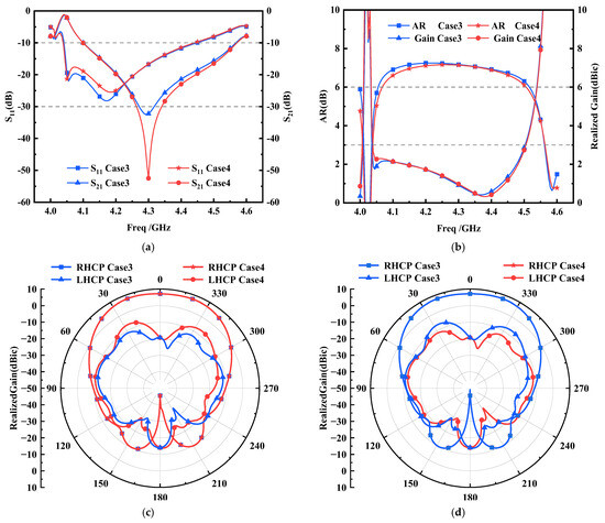
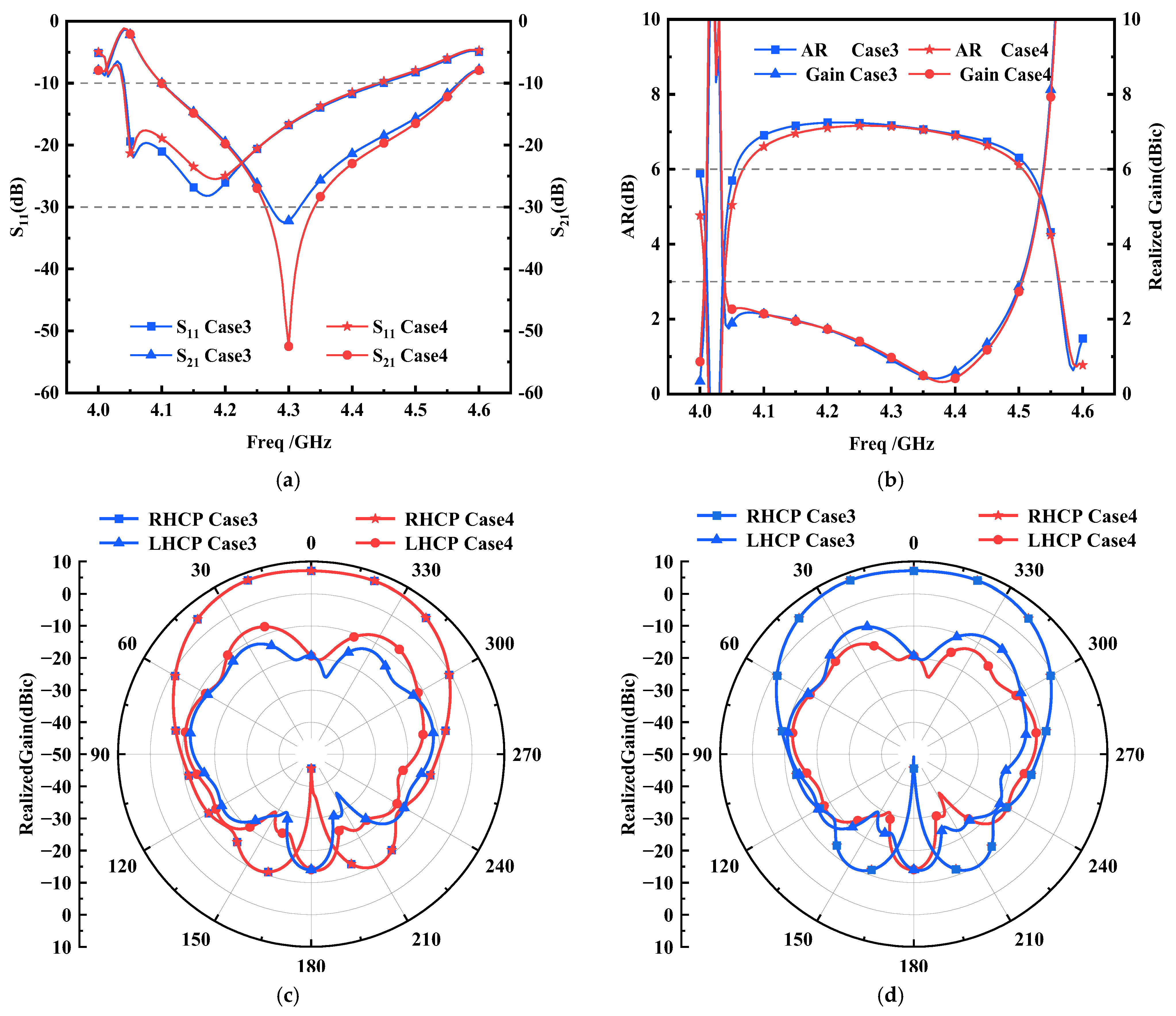
Figure 5 compares Case 3 and Case 4 to evaluate the DFN under the cavity-backed condition. In this practical integration model, the DFN produces a much stronger cancelation effect. As shown in Figure 5a, the cavity-backed antenna without the DFN exhibits a simulated S21 of −32.2 dB near 4.3 GHz. After the DFN is introduced, S21 is reduced to −52.5 dB, corresponding to an isolation improvement of 20.3 dB. This result is consistent with the interpretation that the direct interport coupling and the DFN-induced coupling achieve a more favorable amplitude–phase relationship in the cavity-backed configuration, thereby producing a deeper destructive-interference null.
Figure 5.
Simulated responses of the cavity-backed antenna without and with the DFN: (a) S11 and S21; (b) AR and realized gain; (c) radiation patterns in the xoz plane at 4.3 GHz; (d) radiation patterns in the yoz plane at 4.3 GHz.
The axial ratio and realized gain responses in Figure 5b remain almost unchanged before and after the introduction of the DFN. The radiation patterns in Figure 5c,d also remain generally stable. These results suggest that the deep isolation null in Case 4 is primarily associated with the feeding-network cancelation mechanism rather than with a substantial perturbation of the radiating aperture. Therefore, the DFN improves the transmit–receive isolation while preserving the circularly polarized radiation characteristics of the stacked patch antenna.
The comparison between Figure 4 and Figure 5 further demonstrates that the isolation performance of the DFN depends on the electromagnetic integration environment. The mounting cavity changes the original interport coupling of the multilayer antenna, but it should not be regarded as an independently designed decoupling element. With the same DFN dimensions, the isolation improvement is approximately 5 dB in the cavity-free configuration, as shown by Cases 1 and 2, whereas an improvement of approximately 20.3 dB is obtained in the cavity-backed configuration, as shown by Cases 3 and 4. This difference can be attributed to the joint optimization of the DFN and the final cavity-backed antenna model. The results are consistent with the interpretation that the original coupling and the DFN-induced coupling achieve a more favorable amplitude–phase relationship in Case 4. Therefore, the simulated deep isolation null in Case 4 should be understood as the response of the complete cavity-backed antenna assembly rather than as an independent contribution of the mounting cavity. If the cavity dimensions or the surrounding electromagnetic boundary is changed, the DFN parameters may require re-optimization.
It should also be emphasized that the deep isolation enhancement is narrowband. Although the antenna satisfies the impedance-matching and axial ratio requirements from 4.1 to 4.4 GHz, high transmit–receive isolation is not maintained over this entire operating band. As confirmed by the measured results in Section 3, the isolation is higher than 30 dB only from 4.25 to 4.28 GHz, corresponding to a bandwidth of 30 MHz. Therefore, if more than 30 dB of antenna-domain isolation is required, the occupied signal bandwidth, including the necessary guard bands, should be selected within the measured high-isolation region. Outside this region, the antenna may remain impedance matched and circularly polarized, but the available antenna-domain transmit–receive isolation is reduced.
2.5. Parameter Sensitivity and Possible Sources of Measurement Deviation
The results in Figure 3 constitute a design-parameter sensitivity study rather than a statistical fabrication-tolerance analysis. The parameter ranges are selected to identify the respective roles of the coupled-line spacing and the effective phase-control length during the DFN design process; they do not represent the exact manufacturing tolerances of the fabricated sample.
The results indicate that S1 predominantly controls the depth of the isolation null, whereas ΔL predominantly controls its frequency position. The isolation response is therefore more sensitive to geometrical deviations in the coupled-line and phase-control sections than the impedance and radiation responses. In addition, variations in the nominal substrate parameters, air-gap heights, multilayer alignment, connector and soldering transitions, and cavity assembly may modify either the DFN-associated coupling or the original coupling environment of the radiator.
The small frequency difference between the simulated and measured isolation nulls is attributed to the combined influence of these factors rather than to a single independently identified error source. Because the cancelation is narrowband and depends on a precise complex-field balance, a small variation in the complete antenna assembly may shift or weaken the null. A statistical Monte Carlo tolerance analysis and experimental verification using multiple fabricated samples were not conducted in this work. Such an analysis would be useful for establishing production-oriented dimensional limits and is left for future investigation.
3. Experimental Results
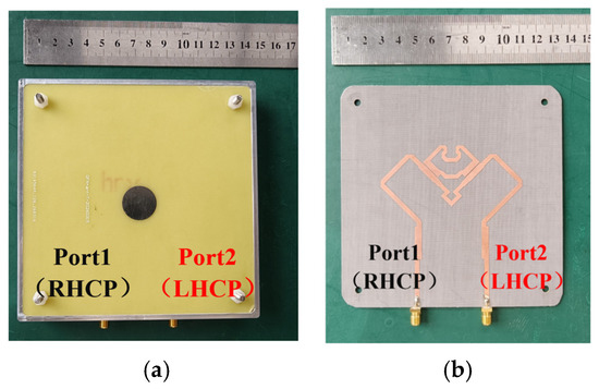
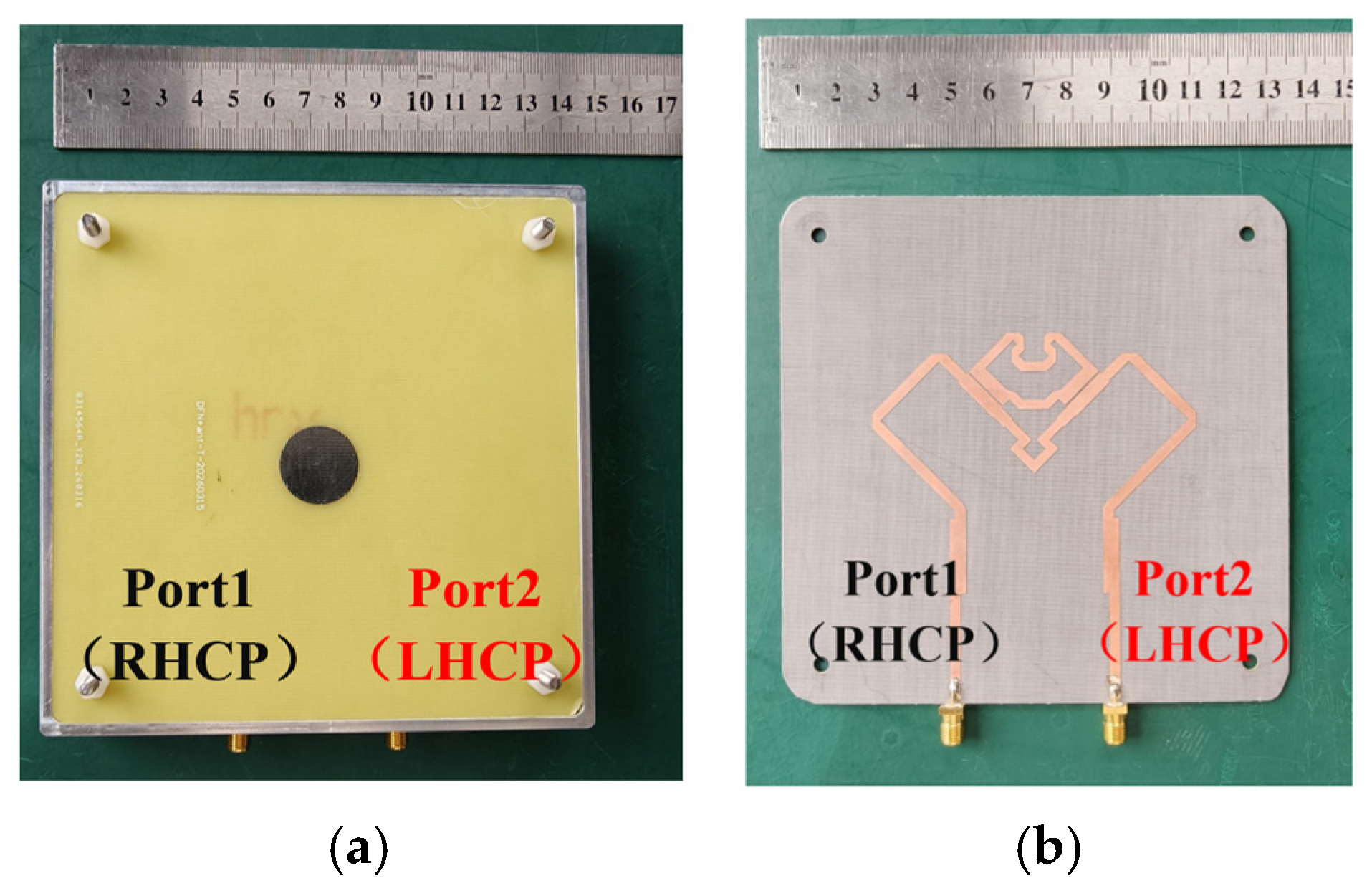
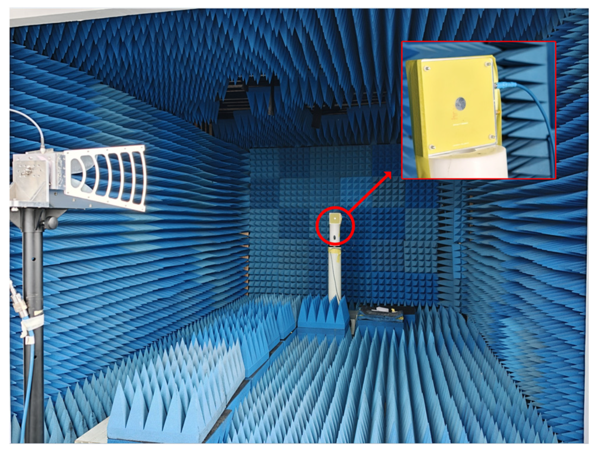
Figure 6 shows the fabricated antenna, including the DFN and the cavity-backed supporting structure. The four two-port S-parameters were measured using an N5232A vector network analyzer. Before measurement, a full two-port short–open–load–through (SOLT) calibration was performed at the ends of the test cables. The far-field radiation characteristics were evaluated in a microwave anechoic chamber using the measurement arrangement shown in Figure 7. The separation between the transmitting antenna and the antenna under test was approximately 3 m, satisfying the far-field condition over the operating frequency band. The realized gain was measured using the gain-comparison method with a reference antenna of known gain. During the measurement of each port, the excited port was connected to the measurement system, whereas the inactive port was terminated with a matched 50 Ω load. The antenna was mounted with its broadside direction aligned with the chamber boresight. The test cables were maintained in a fixed configuration during the measurements to reduce cable-induced variations. A formal measurement uncertainty budget and uncertainty correction were not applied; therefore, the differences between the simulated and measured responses are discussed qualitatively.
Figure 6.
Photographs of the fabricated antenna: (a) top view; (b) bottom view.
Figure 7.
Measurement setup in the microwave anechoic chamber.
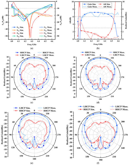
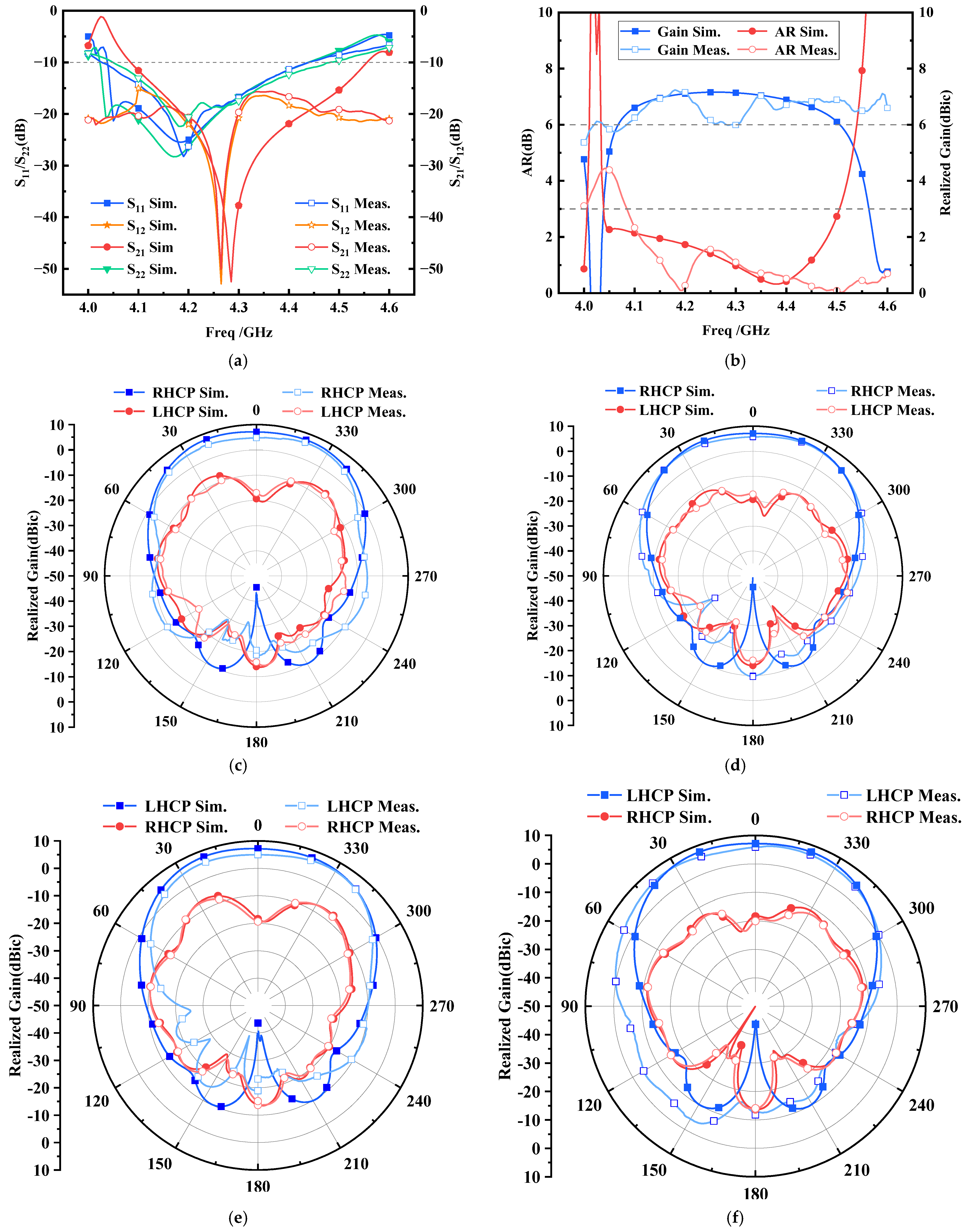
The simulated and measured two-port S-parameters are compared in Figure 8a. For completeness, S11, S22, S21, and S12 are all included. Both measured reflection coefficients satisfy the −10 dB matching criterion from 4.1 to 4.4 GHz. The measured S12 and S21 responses show close agreement, as expected for a passive reciprocal antenna.
Figure 8.
Simulated and measured antenna performance: (a) S-parameters; (b) broadside AR and realized gain under Port 1 excitation; (c) radiation patterns in the xoz plane under Port 1 excitation at 4.3 GHz; (d) radiation patterns in the yoz plane under Port 1 excitation at 4.3 GHz; (e) radiation patterns in the xoz plane under Port 2 excitation at 4.3 GHz; (f) radiation patterns in the yoz plane under Port 2 excitation at 4.3 GHz.
In this work, the antenna operating band is defined by the overlap between the −10 dB impedance bandwidth and the 3 dB broadside axial ratio bandwidth. The high-isolation band is evaluated separately and should not be interpreted as covering the entire antenna operating band. The measured minimum S21 is −50 dB, and the measured isolation is higher than 30 dB from 4.25 to 4.28 GHz. This range has an absolute bandwidth of 30 MHz and a fractional bandwidth of approximately 0.70% around 4.265 GHz. The measured isolation null is slightly shifted relative to the simulated response. As discussed in Section 2.5, this difference is consistent with the combined sensitivity to the DFN dimensions, substrate parameters, multilayer assembly, connector transitions, and cavity-backed integration conditions.
Figure 8b presents the simulated and measured broadside axial ratio and realized gain under Port 1 excitation. The measured axial ratio remains below 3 dB from 4.1 to 4.4 GHz, and the measured peak realized gain reaches approximately 7 dBic. The realized gain remains above approximately 6 dBic over the same frequency interval. Because the available frequency-dependent axial ratio and gain curves in Figure 8b correspond to Port 1 excitation, the panel is explicitly identified as a Port 1 result rather than a combined two-port response.
Figure 8c,d show the radiation patterns under Port 1 excitation, for which RHCP is the co-polarized component and LHCP is the cross-polarized component. Figure 8e,f show the corresponding results under Port 2 excitation, for which LHCP is the co-polarized component and RHCP is the cross-polarized component. For both excitation states, the co-polarized component dominates in the broadside main-beam region, and the measured pattern trends are consistent with the simulated results. The measured half-power beamwidth is approximately 91° in the (xoz) plane under Port 1 excitation.
The combined S-parameter and radiation results show that the DFN generates a deep isolation null near the target frequency without causing an evident deterioration of the broadside circular polarization or the main-beam radiation response. Nevertheless, the deep isolation enhancement is confined to a much narrower frequency range than the impedance and axial ratio operating band.
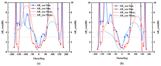
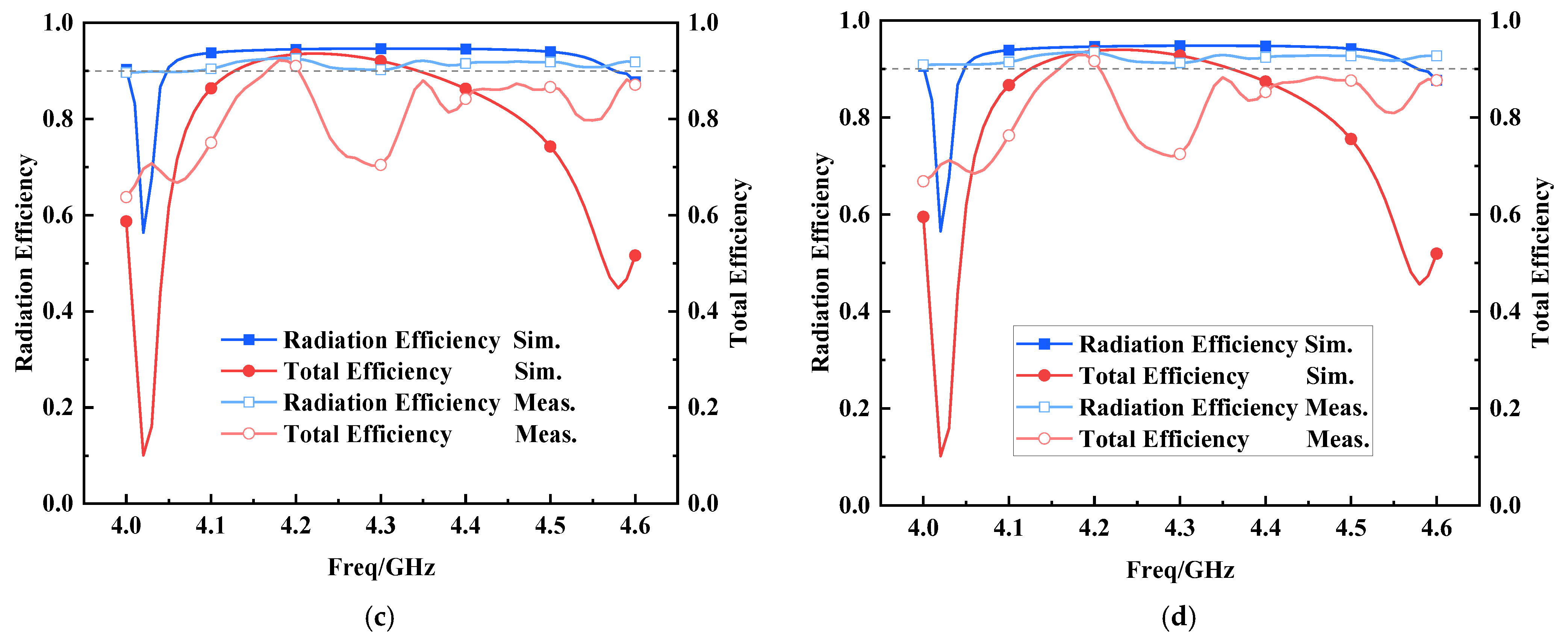
Figure 9 further evaluates the polarization stability and efficiency performance of the proposed antenna. Figure 9a,b show the angular AR responses at 4.3 GHz under Port 1 and Port 2 excitation, respectively. For Port 1 excitation, the antenna radiates RHCP, and the measured AR remains low around the broadside direction in both the xoz and yoz planes. For Port 2 excitation, the antenna radiates LHCP, and similar broadside AR behavior is observed. The measured and simulated angular AR curves show the same overall trend, although some deviations appear at large observation angles. These deviations can be attributed to fabrication tolerances, the cavity-backed configuration, connector/cable effects, and measurement uncertainty in the anechoic chamber. The results indicate that both ports can maintain good circular polarization around the main radiation direction.
Figure 9.
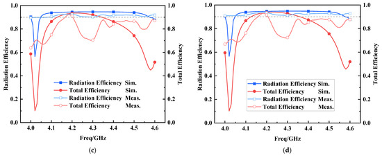
Simulated and measured polarization and efficiency characteristics: (a) angular axial ratio under Port 1 excitation at 4.3 GHz; (b) angular axial ratio under Port 2 excitation at 4.3 GHz; (c) radiation and total efficiencies under Port 1 excitation; (d) radiation and total efficiencies under Port 2 excitation.
Figure 9 further evaluates the angular axial ratio and efficiency characteristics of the two antenna ports. Under Port 1 excitation, the measured broadside axial ratio at 4.3 GHz is approximately 1.10 dB. The measured 3 dB axial ratio angular ranges are approximately −21° to 41° in the xoz plane and −31° to 39° in the yoz plane, corresponding to angular widths of 62° and 70°, respectively. Under Port 2 excitation, the measured broadside axial ratio is approximately 1.12 dB. The corresponding 3 dB angular ranges are approximately −63° to 27° in the xoz plane and −32° to 54° in the yoz plane, corresponding to angular widths of 90° and 86°, respectively.
The angular axial ratio responses are not perfectly symmetric about the broadside direction. This behavior is attributed to the asymmetric feeding layout, connector transition, the practical cavity-backed boundary, and multilayer fabrication and assembly deviations. Nevertheless, the main-beam regions of both ports maintain axial ratios below 3 dB, supporting RHCP operation under Port 1 excitation and LHCP operation under Port 2 excitation.
Figure 9c,d present the simulated and measured radiation and total efficiencies for Port 1 and Port 2, respectively. The radiation-efficiency results indicate that the multilayer radiator and the DFN do not introduce a severe dissipation penalty within the 4.1–4.4 GHz operating band. The total efficiency is lower than the radiation efficiency because it includes the effects of impedance mismatch in addition to conductor and dielectric losses.
The available measurements provide only the overall radiation and total efficiencies of the complete antenna assembly. The individual losses associated with the FR4 layers, the Taconic substrate, the DFN, connectors, soldering transitions, and cavity-backed structure cannot be uniquely separated from these data. Therefore, a component-by-component loss budget is not claimed in this work.
Table 3 compares the proposed antenna with previously reported circularly polarized and dual-circularly polarized STAR antennas [11,13,14,21]. Because the reported studies employ different isolation thresholds and operating-band definitions, peak isolation alone does not provide a complete comparison. The table therefore lists the reported operating band, the isolation criterion adopted in each reference, the corresponding isolation frequency range, peak isolation, normalized size, realized gain, beamwidth, and principal decoupling approach. The values are reproduced according to the definitions used in the original references and should not be interpreted as having being obtained under an identical evaluation criterion.
Table 3.
Performance comparison with reported antennas.
Among the compared antennas, the proposed design provides a measured peak isolation of 50 dB. However, the isolation higher than 30 dB is limited to 4.25–4.28 GHz, corresponding to only 30 MHz, and the normalized overall size is larger than that of several reported designs. The proposed antenna therefore does not provide the widest isolation bandwidth or the smallest electrical size. Its main distinction is the generation of a deep target-frequency isolation null using a feeding-network-based cancelation path without adding patterned EBG, DGS, or parasitic decoupling elements to the radiating aperture. This trade-off makes the design more suitable for applications that prioritize high isolation at a specified narrowband channel than for broadband or highly miniaturized STAR front ends.
4. Conclusions
A dual-circularly polarized STAR patch antenna using an inverse-cancelation DFN has been investigated. The DFN introduces an additional coupling contribution between the RHCP and LHCP feeding paths, and its coupled-line spacing and phase-control length primarily determine the depth and frequency position of the resulting isolation null. The parameter study and the comparisons between the cavity-free and cavity-backed models show that the cancelation response is a property of the complete integrated antenna rather than of the isolated DFN alone. The practical mounting cavity changes the original coupling environment and must therefore be included during the final optimization.
The fabricated antenna maintains overlapping −10 dB impedance and 3 dB axial ratio bandwidths from 4.1 to 4.4 GHz, while the measured isolation higher than 30 dB is confined to 4.25–4.28 GHz. The latter corresponds to a 30 MHz bandwidth, or approximately 0.70% around 4.265 GHz. The principal benefit of the design is thus a deep target-frequency isolation null without patterned aperture-level decoupling elements, rather than broadband isolation or antenna miniaturization.
The proposed approach also has clear limitations. The isolation null is sensitive to the DFN dimensions, material parameters, connector transitions, multilayer alignment, air-gap accuracy, and cavity assembly. A change in the enclosure or integration boundary may require retuning of the DFN. In addition, the present parameter study does not constitute a statistical manufacturing-tolerance analysis, and the available efficiency measurements do not permit a component-by-component loss decomposition. Future work may consider multi-branch or multi-zero DFNs for wider isolation bandwidth, reduced-sensitivity network topologies, and statistical tolerance verification using multiple fabricated samples.
Author Contributions
Conceptualization, T.L. and K.L.; methodology, T.L. and K.L.; software, T.L. and F.H.; validation, Q.W., S.X. and K.L.; formal analysis, T.L. and H.L.; investigation, T.L. and F.H.; resources, K.L. and Q.W.; data curation, T.L. and S.X.; writing—original draft preparation, T.L.; writing—review and editing, K.L., F.H., Q.W., S.X. and H.L.; visualization, T.L. and H.L.; supervision, K.L.; project administration, K.L.; funding acquisition, K.L. All authors have read and agreed to the published version of the manuscript.
Funding
This research was partly funded by the Project of the National Key Laboratory of Electromagnetic Energy under Grant 614221725020302 and the Natural Science Foundation of Hubei Province under Grant JCZRMS202602258.
Data Availability Statement
The original contributions presented in this study are included in the article. Further inquiries can be directed to the corresponding author.
Conflicts of Interest
The authors declare no conflicts of interest.
References
- Chen, Y.; Ding, C.; Jia, Y.; Liu, Y. Antenna/propagation domain self-interference cancellation (SIC) for in-band full-duplex wireless communication systems. Sensors 2022, 22, 1699. [Google Scholar] [CrossRef] [Scilit] [PubMed]
- Nikkhah, M.R.; Wu, J.; Luyen, H.; Behdad, N. A concurrently dual-polarized, simultaneous transmit and receive (STAR) antenna. IEEE Trans. Antennas Propag. 2020, 68, 5935–5944. [Google Scholar] [CrossRef] [Scilit]
- Chen, Y.; Hua, H.; Xu, J.; Ng, D.W.K. ISAC meets SWIPT: Multi-functional wireless systems integrating sensing, communication, and powering. IEEE Trans. Wirel. Commun. 2024, 23, 8264–8280. [Google Scholar] [CrossRef] [Scilit]
- Ma, L.; Zhang, Z.; Tong, F.; Liu, S.; Gu, C. A compact co-linearly polarized full-duplex patch antenna with high isolation and broadside symmetrical radiation pattern for integrated sensing and communication in IoT. IEEE Internet Things J. 2025, 12, 21630–21645. [Google Scholar] [CrossRef] [Scilit]
- Zeng, Y.; Liu, H.; Liu, S.; Du, L.; Wang, Z. Wideband circularly polarized quadrifilar helix antenna with hemispherical coverage. IEEE Antennas Wirel. Propag. Lett. 2026, 25, 1344–1348. [Google Scholar] [CrossRef] [Scilit]
- Yu, W.; Mao, C.; Ou, J.; Zhang, X.Y. Shared-aperture dual-circularly polarized phased array antenna with small frequency ratio for satellite-assisted IoT communications. IEEE Internet Things J. 2026, 13, 4537–4545. [Google Scholar] [CrossRef] [Scilit]
- Yang, Y.-H.; Wang, S.-C.; Zhu, Z.-J.; Zhang, Y.-H.; Zhang, L.-K.; Lu, X.-L.; Zhou, S.-G. A dual circularly polarized phased array antenna with enhanced polarization purity for multi-azimuth plane scanning. IEEE Trans. Antennas Propag. 2026, 74, 4067–4080. [Google Scholar] [CrossRef] [Scilit]
- Huang, H.; Li, X.; Liu, Y. A low-profile, dual-polarized patch antenna for 5G MIMO application. IEEE Trans. Antennas Propag. 2019, 67, 1275–1279. [Google Scholar] [CrossRef] [Scilit]
- Chen, J.-X.; Yan, T.-Y.; Yang, J.-Y.; Ding, X.-H.; Yang, L.-L.; Li, Y. Dual-polarized heterogeneous stacked patch antenna with stable radiation performance and high efficiency. IEEE Antennas Wirel. Propag. Lett. 2024, 23, 2421–2425. [Google Scholar] [CrossRef] [Scilit]
- Vishwakarma, M.K.; Kishor, J.; Ghosh, J. Wideband SDRR-loaded circularly polarized MIMO dielectric resonator antenna for sub-6 GHz wireless applications. Phys. Scr. 2025, 100, 075575. [Google Scholar] [CrossRef] [Scilit]
- Qi, Z.-Y.; He, B.; Yi, D.; Zhang, Q.; Wang, F.; Xiong, X.; Tang, M.-C. Co-circularly polarized and in-band full-duplex cavity-backed slot-antenna pair within shared cavity for RFID application. IEEE Trans. Antennas Propag. 2025, 73, 7172–7181. [Google Scholar] [CrossRef] [Scilit]
- Tran-Huy, H.; Le-Tuan, T.; Kim-Thi, P.; Hussain, N.; Nguyen, T.K.; Nguyen-Trong, N. Wideband high-isolation dual-circularly polarized co-aperture antenna using non-uniform parasitic elements. IEEE Antennas Wirel. Propag. Lett. 2026, 25, 911–915. [Google Scholar] [CrossRef] [Scilit]
- Xie, M.; Wei, X.; Tang, Y.; Hu, D. Dual circularly polarized monostatic STAR antenna with enhanced isolation. J. Syst. Eng. Electron. 2025, 36, 73–81. [Google Scholar] [CrossRef] [Scilit]
- Wang, J.; Wei, X.; Sun, J.; Xie, M. Isolation enhancement of dual-circularly polarized antenna using hierarchical decoupling scheme. IEEE Antennas Wirel. Propag. Lett. 2024, 23, 2391–2395. [Google Scholar] [CrossRef] [Scilit]
- Nawaz, H.; Tekin, I. Dual-polarized, differential fed microstrip patch antennas with very high interport isolation for full-duplex communication. IEEE Trans. Antennas Propag. 2017, 65, 7355–7360. [Google Scholar] [CrossRef] [Scilit]
- Zhang, Y.-M.; Li, J.-L. Differential-series-fed dual-polarized traveling-wave array for full-duplex applications. IEEE Trans. Antennas Propag. 2020, 68, 4097–4102. [Google Scholar] [CrossRef] [Scilit]
- Wang, Z.; Wu, Q. A novel decoupling feeding network for circularly polarized patch arrays using orthogonal mode decomposition. IEEE Trans. Antennas Propag. 2023, 71, 1448–1457. [Google Scholar] [CrossRef] [Scilit]
- Tan, Q.; Luk, K.-M. Wideband circularly polarized antenna for in-band full-duplex application. In Proceedings of the 2024 IEEE International Symposium on Antennas and Propagation and INC/USNC-URSI Radio Science Meeting, Florence, Italy, 14–19 July 2024. [Google Scholar] [CrossRef] [Scilit]
- Wu, D.; Sun, Y.-X.; Wang, B.; Lian, R. A compact, monostatic, co-circularly polarized simultaneous transmit and receive (STAR) antenna with high isolation. IEEE Antennas Wirel. Propag. Lett. 2020, 19, 1127–1131. [Google Scholar] [CrossRef] [Scilit]
- Fu, S.; Wang, Y.; Li, C.; Xu, Z. Dual-circularly polarized STAR antenna array with high realized gain and enhanced isolation. IEEE Antennas Wirel. Propag. Lett. 2024, 23, 4777–4781. [Google Scholar] [CrossRef] [Scilit]
- Dao-Duc, T.; Tran-Viet, D.-N.; Tien, D.N.; Quoc, D.N.; Nguyen, T.T.-L.; Tran-Huy, H. A compact co-aperture dual-sense circularly polarized antenna for simultaneous transmit and receive systems. PLoS ONE 2024, 19, e0304414. [Google Scholar] [CrossRef] [Scilit] [PubMed]
- Wang, C.; Xu, H.-X.; Zhu, R.; Ding, H.; Li, B.; Wang, X.; Yang, C.; Lu, Y. 3-D-printed pentahedral polarization-division transmissive metadevice with versatile wavefronts. IEEE Trans. Antennas Propag. 2026, 74, 4915–4920. [Google Scholar] [CrossRef] [Scilit]
- Zou, X.-J.; Wang, Y.-W.; Zong, B.-F.; Xu, X.-G.; Han, L.-X.; Zhu, H.; Song, W.; Tan, M.; Du, H.-N. Miniaturized low-profile ultrawideband antipodal Vivaldi antenna array loaded with edge techniques. IEEE Trans. Antennas Propag. 2026, 74, 1156–1161. [Google Scholar] [CrossRef] [Scilit]


Disclaimer/Publisher’s Note: The statements, opinions and data contained in all publications are solely those of the individual author(s) and contributor(s) and not of MDPI and/or the editor(s). MDPI and/or the editor(s) disclaim responsibility for any injury to people or property resulting from any ideas, methods, instructions or products referred to in the content. |
© 2026 by the authors. Licensee MDPI, Basel, Switzerland. This article is an open access article distributed under the terms and conditions of the Creative Commons Attribution (CC BY) license.