


Abstract
In power systems, nonlinear loads cause harmonic distortion, adversely affecting sensitive equipment such as induction motors, power electronics, and variable-speed drives. This paper presents a novel control strategy that integrates with existing hierarchical control systems to mitigate voltage imbalances and harmonic disturbances in AC-islanded microgrids. The proposed method utilizes selective harmonic order filtering through multiple second-order generalized integrators (MSOGI) to extract negative, positive, and harmonic order components. The distributed generation (DG) unit control mechanism is designed to immediately correct voltage imbalances and harmonic disruptions, distributing the compensatory load evenly to rectify real and reactive power imbalances and harmonic disturbances. The microgrid’s control architecture primarily includes droop controllers for real and reactive power of positive sequences, voltage and current regulation inner control loops, an additional loop for correcting imbalances and harmonics, and secondary controllers to maintain voltage magnitude and frequency at nominal levels, ensuring high-quality voltage at the point of common coupling (PCC). The effectiveness of this approach is demonstrated through simulation results on the MATLAB/Simulink platform, proving its ability to effectively mitigate voltage imbalances and harmonic issues with the total harmonic of voltage reduced to approximately THDv = 0.5% and voltage unbalance factor (VUF) within approximately 0.1%.
1. Introduction
Microgrids are essential for developing next-generation clean energy systems, focusing on enhancing their information technology for scalable, reliable, and automated energy control. These systems are compact networks of distributed energy resources (DERs) in various configurations, considered crucial for transitioning from traditional, one-way power grids. Microgrids offer significant improvements in power quality for all loads and boost system efficiency and stability. The trend towards decentralized power generation is emphasized by the increased adoption and implementation of microgrid technologies, motivated by the limitations of centralized power systems. Consequently, microgrid stations are being widely deployed and tested worldwide to refine their operation and are especially useful in remote and islanded areas, underlining their broad application potential [1,2,3,4,5].
Microgrid configurations typically include generation units with renewable and traditional energy sources like solar panels, wind turbines, hydropower, and biofuel systems. The energy storage part, critical for grid resilience and cost optimization, often involves batteries or a mix of batteries and supercapacitors. These are crucial for ensuring power quality, frequency control, and smoothing out renewable energy supply fluctuations. Microgrids are increasingly recognized in North America, Europe, and Asia Pacific. They are expected to expand in remote, industrial, or islanded areas, thanks to their ability to manage various operational challenges [5,6,7,8,9].
Voltage imbalances in energy systems can lead to significant losses and instability, potentially harming equipment like induction motors and electronic devices. Addressing total harmonic distortion (THD) and VUF limits is essential to avoid damage and ensure system performance [10]. The International Electrotechnical Commission (IEC) sets a voltage unbalance limit of 2% to prevent such issues [11]. Strategies to manage these challenges include regulating positive-sequence voltage, eliminating negative-sequence voltage, and managing peak currents to protect equipment and maintain voltage stability during network disturbances [12,13,14,15].
Microgrid research encompasses foundational studies and addresses specific design and control challenges, including for small satellites [2], secure energy management in hybrid systems [3], economic assessments [4], and advanced protection and operation strategies [5,6]. The research extends to decision-making for microgrid adoption [7], renewable energy integration [8], autonomous voltage control [9,10], advanced control methods for voltage stability [11], and voltage and harmonics management [12,13]. The significance of simulation tools for educational purposes in microgrid control is noted [16], along with the evaluation of solar microgrids in emerging markets [17] and protective strategies for hybrid AC/DC microgrids [18], This comprehensive research highlights microgrid technology’s dynamic and evolving field, emphasizing its importance in energy systems engineering. Reference [19] offers a thorough analysis, optimization tactics, and microgrid control methods. Individual customers can save money in a microgrid settlement through energy management, which pools renewable energy resources integrated with buildings. Bend control is one of the most popular control strategies in microgrid systems because it is inexpensive and can function without a communication link. The study builds a master-slave-based PI-based integrated under-discharge control strategy to protect microgrids against unintentional post-islanding conditions and guarantee stable operation. A microgrid storage system is part of the disposal strategy, which allows the loads to be extended for a predetermined amount of time once the frequency is within the operational stability and maximum [20,21,22,23,24].
Current control strategies feature a system that enables remote passive sequencing and consistent voltage compensation across all nodes in an AC microgrid powered by inverters. These strategies focus on adjusting the negative-sequence output voltage of the inverters to address voltage imbalances at remote nodes. For instance, the target might be to mitigate the negative-sequence output of the inverters or to intentionally reduce the voltage at specific transformers to affect their operation. This adjustment strategy involves decreasing local loads while increasing those on other inverters. The previously proposed controller achieves the following dual objectives: reducing the negative-sequence voltage at distant nodes and providing equitable compensation through the inverter. This controller design incorporates built-in parallel functionality, making it practical and plug-and-play compared to other passive sequence controllers. Prior research also introduced a control scheme to limit current flows in the inverter network. Unlike other systems, this approach effectively reduces load voltage imbalances, even during line-to-line short circuits, and supports linear and nonlinear loads without prior load-specific information [24,25,26]
Additionally, the study addresses the impact of unbalanced and nonlinear loads on microgrid performance and device aging. Nonlinear loads create non-sinusoidal current waveforms, leading to higher-order harmonic distortions in the voltage output and potentially decreasing device efficiency and lifespan. Techniques to adjust the voltage output and minimize these harmonics are proposed, along with a new control approach for balanced voltage compensation in inverter-based AC microgrids, ensuring the system’s efficient and reliable function [27,28]. This approach reflects the ongoing initiatives to improve renewable energy integration, enhance grid stability, and ensure fair power distribution in varied operational scenarios.
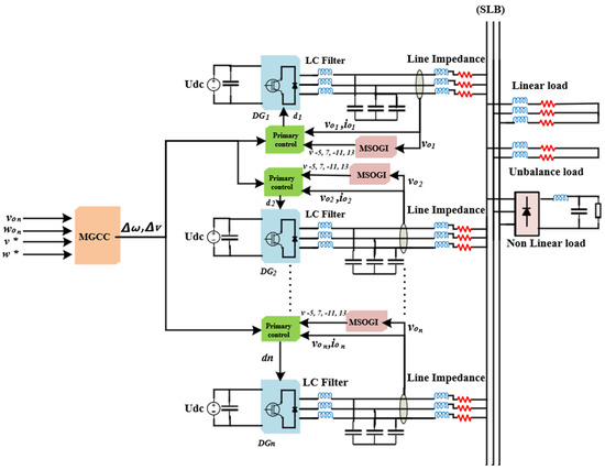
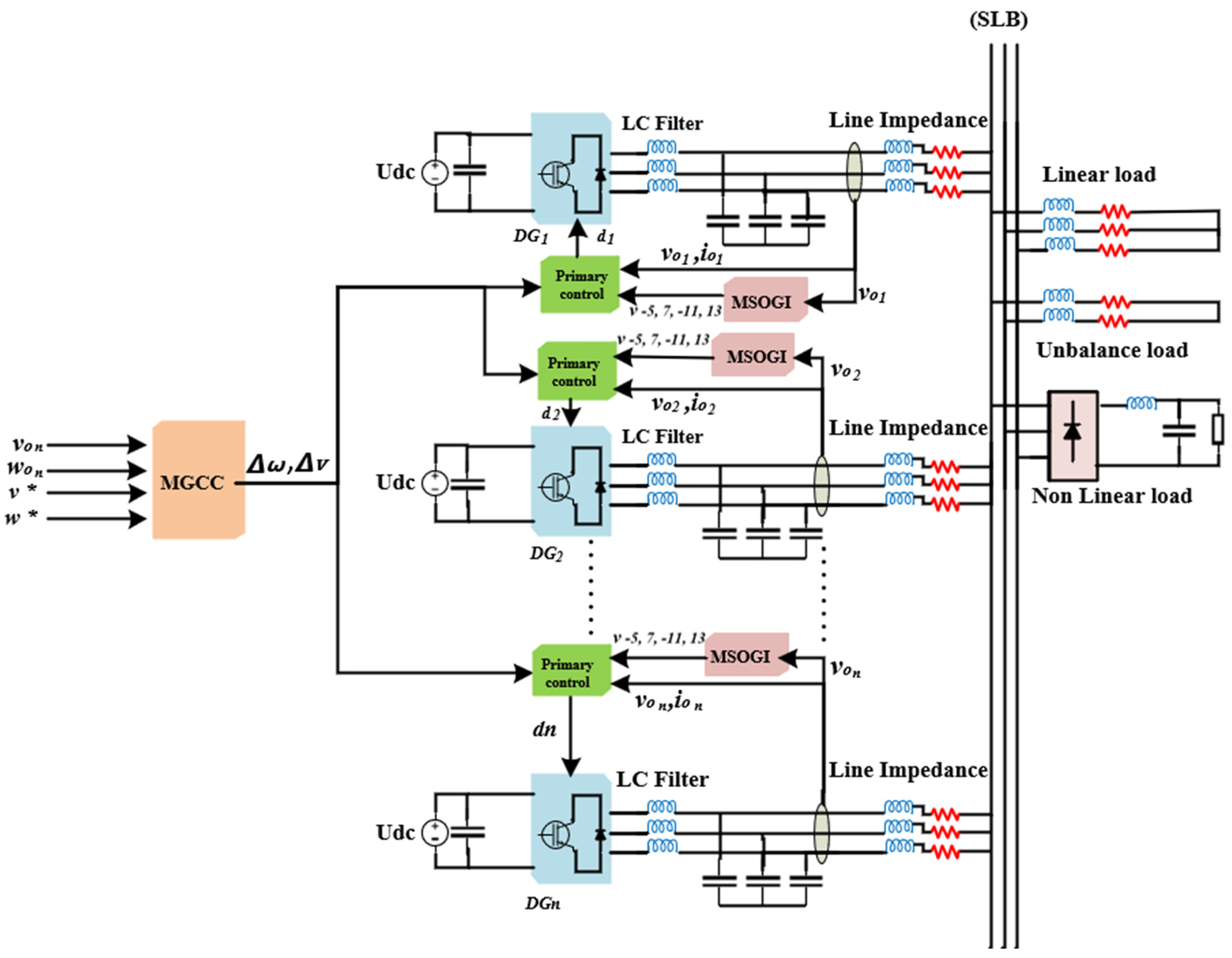
The primary goal of this study is to fully offset unbalanced voltage by removing the opposing sequence and suppressing harmonics, particularly the -5th, 7th, -11th, and 13rd orders, in inverter-based microgrids. This comprehensive strategy also addresses power quality issues from unbalanced and nonlinear loads, as shown in Figure 1. This is achieved through a novel control scheme that integrates with the existing hierarchical control strategy at the primary level, eliminating the need for communication.
Figure 1.
Typical structure of MG with multiple parallel-connected DG units.
The key contributions of this paper, which outperform the current strategies found in the literature, include the following:
- The development of a novel control scheme for neutralizing voltage imbalances and harmonics in AC-islanded microgrids.
- The strategy mitigates unbalanced voltage and harmonics, nearing zero levels, surpassing the performance of existing strategies.
- The proposed loop for mitigating the negative sequence and harmonics sequence uses one gain to compensate for both the negative sequence and harmonics sequence ( to reach a balanced system with fundamental frequencies, unlike the reference [13]. In reference [13], two gains are used, one for negative and another for harmonics, which must be tuned and concisely between them according to the variable load. In addition, in this reference, the complex control structure compensates for the harmonic and unbalanced voltage in primary and secondary layers, implying the need for communication service. This paper does not need communication issues; the proposed loop is used in the local control layer.
This paper begins with the introduction, followed by Section 2, which describes the problem. The Section 3 details the proposed control scheme. Then, the Section 4 offers stability analysis, and the Section 5 provides simulation results. In the end, the main conclusions of the research are provided.
2. Problem Formulation
2.1. System Description
Distribution networks face challenges from single-phase loads, leading to unbalanced voltages and synchronization issues. These loads cause harmonics and voltage imbalances, resulting in losses, system instability, and equipment damage. Adhering to THD and VUF standards is crucial [10,11].
The IEC sets a 2% voltage unbalance limit to address these problems. Improving device performance under unstable conditions involves regulating the voltage’s positive sequence, canceling the voltage’s negative sequence, and using peak current limiters [14,15].
Managing harmonic voltage distortion and power distribution challenges includes maintaining energy supply and voltage quality while considering environmental and economic factors. Distributed generation (DG) aims to ensure reliable supply, improve power quality, reduce emissions, and minimize losses, leading to small MGs that operate in grid-connected or islanded modes. Islanded MGs are more prone to power quality issues, requiring the management of harmonics and voltage imbalances. Balanced systems have electrical phases shifted by 120 degrees, maintaining consistent frequency and voltage waveforms, and can be expressed mathematically as follows:
2.2. Problem Identification
Unbalanced and nonlinear loads significantly impact power systems and MG by causing voltage imbalances and generating harmonics [12,13]. These issues lead to inefficient operation, increased losses, and potential damage to equipment due to overheating and excess stress. Poor power quality results from these imbalances, affecting the stability and reliability of the entire system. Additionally, the performance of protective devices can be compromised, increasing the risk of unsafe conditions. Effective mitigation strategies are crucial to maintaining system stability, reducing losses, and ensuring reliable operation in the presence of such loads.
2.3. Objective
The aim is to address the issues of voltage imbalance stemming from imbalanced loads and to mitigate voltage harmonics arising from nonlinear loads simultaneously. The subsequent mathematical equations illustrate that addressing the imbalance involves diminishing the negative sequence in the voltage. Concurrently, harmonic compensation is accomplished by extracting harmonic voltages and reducing distortion in the output power, ultimately achieving a stable state. This paper uses MSOGI to extract negative, positive, and harmonic order components. The proposed unbalanced and harmonics compensation mathematics equations for output power can be presented as follows:
The power distortion can be calculated as follows:
The conductance used to calculate the current compensation is indicated in Equation (7):
where, is the compensation gain.
Finally, the current equation used to eliminate negative sequences and harmonic voltage is presented in Equation (8).
where are the negative and harmonic voltages, respectively, that are extracted by filtering-based SOGI and denotes harmonics orders, especially , while G is the estimated conductance. From (4) to (7), is the distortion power, and and are the RMS active and reactive powers, respectively.
The following section explains the proposed control scheme for eliminating unbalanced and harmonic voltages.
3. Proposed Control Scheme
The proposed control scheme addresses harmonic and unbalanced voltages in multiple MG. The core of this system is the MSOGI. The MSOGI is an advanced signal-processing tool used in microgrids to detect and mitigate harmonic distortions in electrical signals. MSOGI can isolate and extract various harmonic components by employing multiple integrator blocks tuned to different frequencies. This enhances the microgrid’s stability, efficiency, and power quality by ensuring cleaner, more stable voltage and current waveforms. Its ability to handle multiple harmonics in real-time makes it essential for maintaining high performance in modern energy systems [27]. MSOGI obtains the total harmonic distortion, estimated capacitance-voltage, and zero sequence component, allowing fast detection with a low computational burden. It has been demonstrated that the previously suggested methods have identified and isolated faults at various points within the network during fault types with various fault resistance locations.
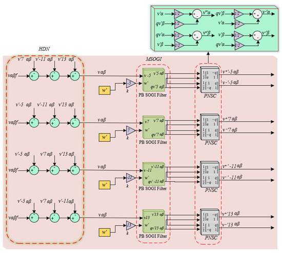
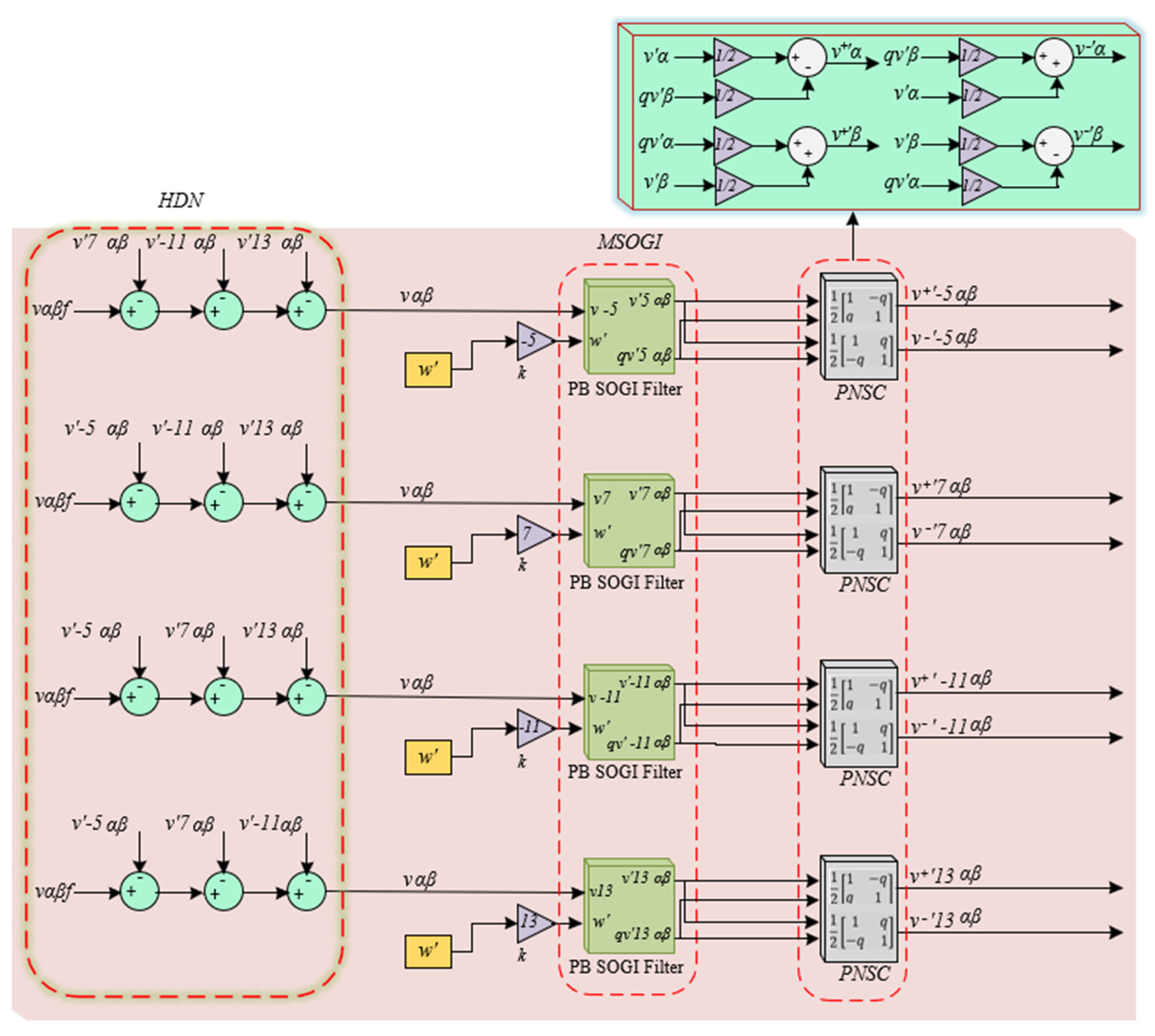
Furthermore, this approach proved the most effective since it outperforms the traditional differential relay protection system regarding accuracy and response time. To estimate the fundamental and harmonic components of the network, MSOGI depends on several parallel SOGIs operating concurrently in parallel, as shown in Figure 2. MSOGI uses a cross-feedback cancellation network to eliminate superfluousness. Additionally, there is some ability to filter out harmonics in the system input voltage using the adaptive SOGI introduced earlier. However, the filter performance will be subpar for harmonics close to the SOG resonance frequency. The static gain in SOGI (k) can be changed to a lower value to counteract this effect, but doing so will slow down the system response. Adding a harmonic decoupling network (HDN) to the system, as shown in Figure 2, solves this problem. The HDN provides a cross-feedback network that enables each parallel branch (PB) SOGI to be tuned to its frequency to provide input to other PB SOGIs. The filtered components are processed through positive and negative sequence (PNSC) to separate and compute the positive and negative sequence components. A simulation was set up using the same harmonics used in this paper’s verification part to verify the operation of the HDN. The input voltage (vαβf) included harmonics at the 5th, 7th, 11th, and 13th and the resonance frequency of SOGI was called to differentiate it from the input frequency w. Also, represent output signals in the quadrature of the adaptive filter [26].
Figure 2.
MSOGI structure for fundamental and harmonic extraction.
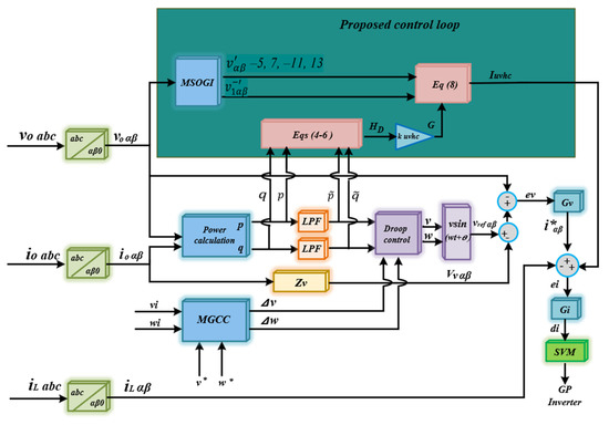
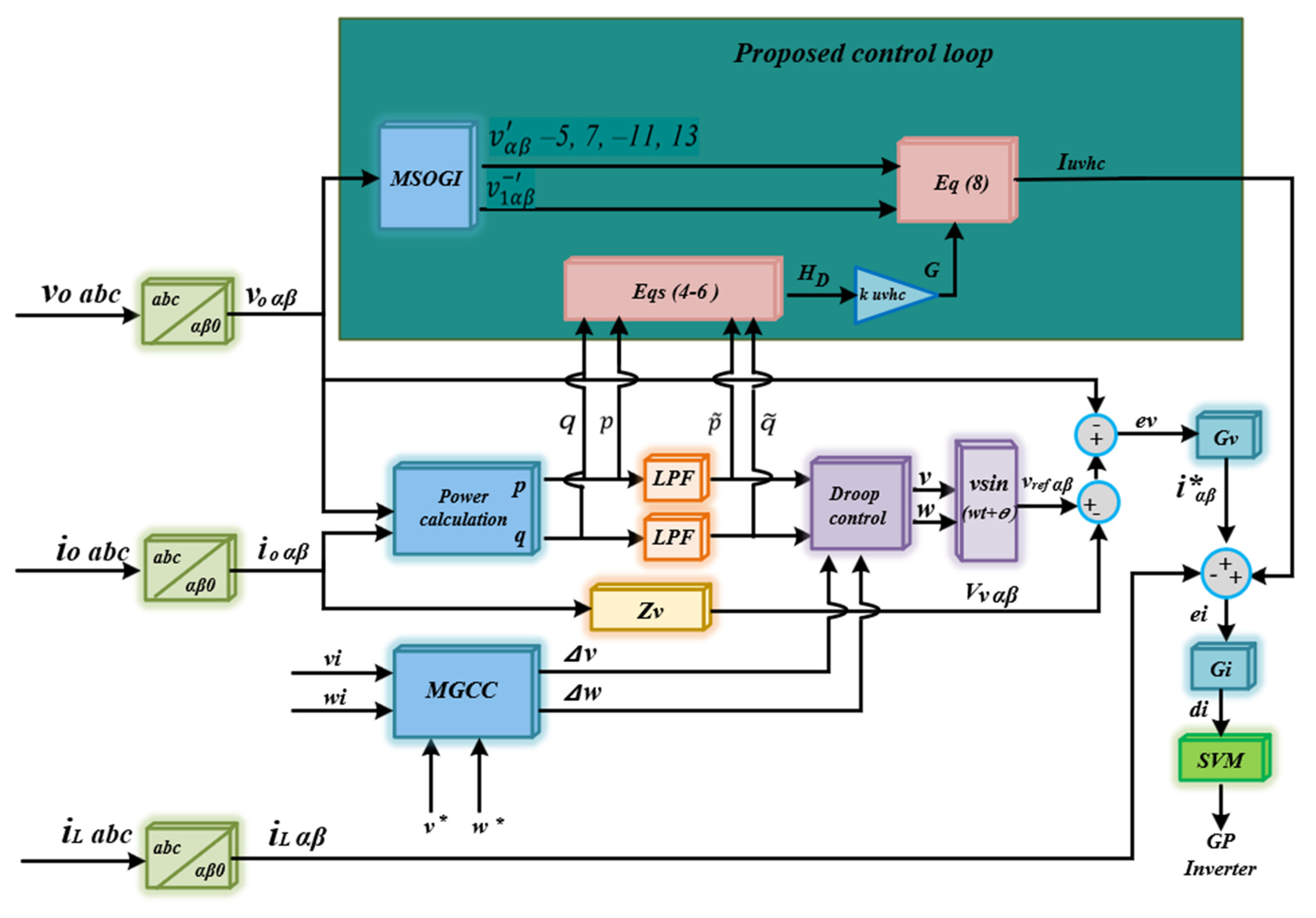
The MSOGI extracts both the positive and negative sequences and the harmonic voltage components. By leveraging the MSOGI, the system can effectively separate the desired fundamental frequency components from the undesired harmonic distortions in the voltage waveform. Subsequently, the estimated conductance (G) is determined using the distortion power, denoted as , as shown in Figure 3, which represents the proposed control scheme. This conductance value is multiplied by a harmonic gain specified in Equations (7) and (8). This step is vital as it calculates the compensating current necessary to rectify the voltage waveform. The setup illustrated in Figure 3 processes the amended harmonic and negative-sequence voltages and modifies them as emphasized. These modifications produce a compensation current that aligns precisely with a specified reference current. The reference current and compensation current are then compared with the corresponding inverter current (). This alignment guarantees that the system’s output adheres to compliance standards, a frequently essential aspect in power systems.
Figure 3.
Block diagram of the proposed control scheme for the islanded microgrid.
3.1. Primary Control
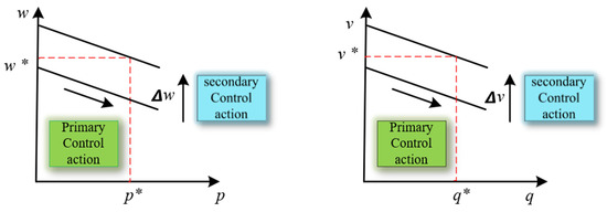
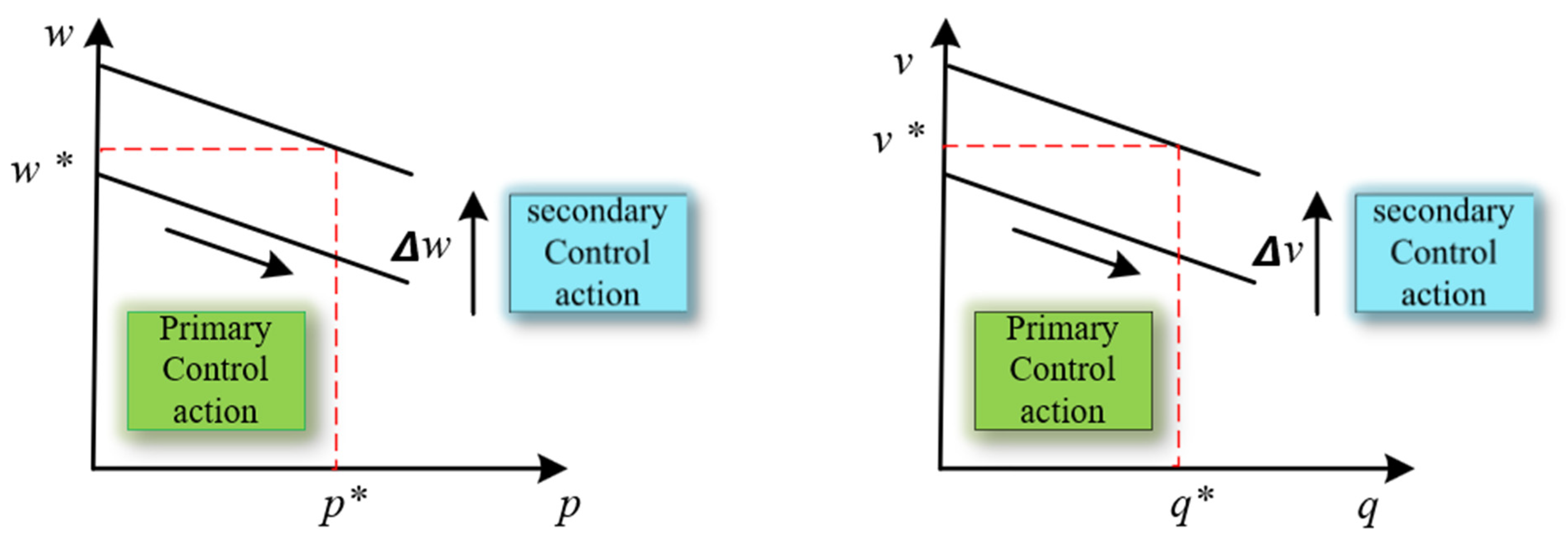
This level is the interface with local inverters in MG, which is crucial for regulating power through voltage and frequency adjustments. Droop control facilitates the synchronous operation of generators by adjusting the frequency to distribute the load as network power increases. It integrates feedback mechanisms with voltage and frequency regulation. Due to the need for extensive communication infrastructure and the risk of single-point failure, droop control is preferred over secondary configurations. Primary control uses voltage source inverter (VSI) controllers. Unlike traditional systems with inherent inertia, these systems use electronic connections, requiring rapid response capabilities for stability. Droop control has limitations, causing voltage and frequency variations under different loads. Thus, the secondary layer adjusts voltage and frequency to their normal values, as seen in Figure 4.
Figure 4.
Primary and secondary control actions.
The basic equations for the primary layer based on the droop method are expressed in Equations (9) and (10).
where and are the droop coefficients, and are the active and reactive powers, respectively, and and are the nominal values of the DG angular frequency and voltage magnitude. At the same time, represents reference voltage amplitude and is the frequency of the inverter.
The active and reactive power in Equations (9) and (10) can be calculated as follows:
where and are the harmonics’ active and reactive powers and can be calculated with the same Equations (11) and (12) but processed by a low-pass filter (LPF).
and , and the measured DG voltage and current, are at fundamental frequency in the stationary reference frame. The DG units share power using the positive-sequence reactive power-voltage droop control method and the positive-sequence active power-frequency control method.
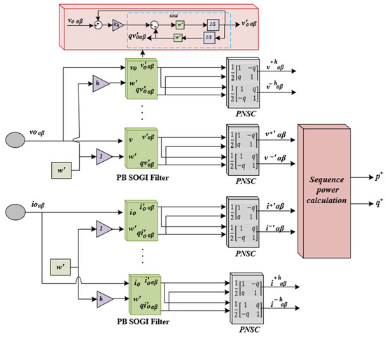
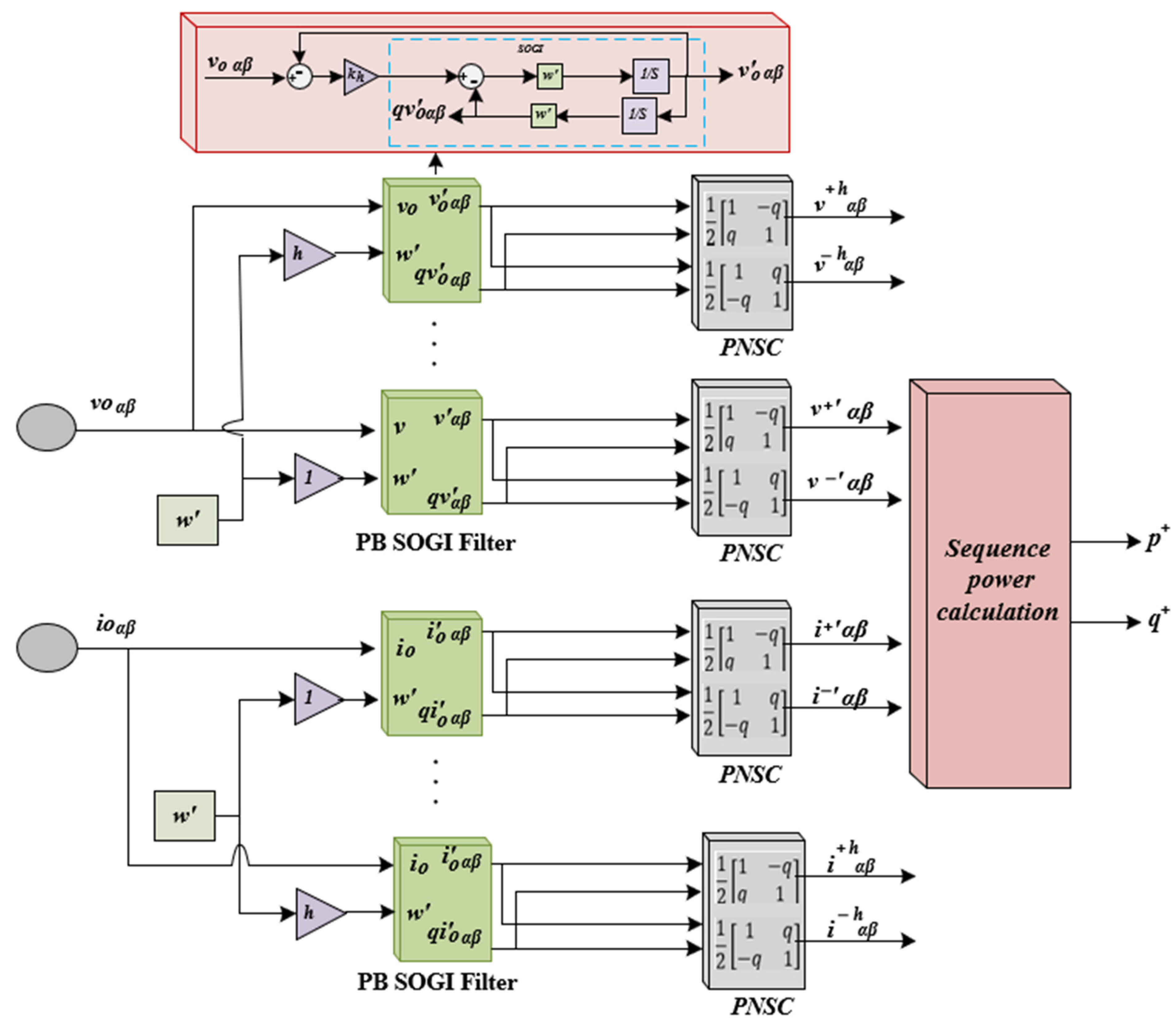
The positive- and negative-sequence components must be extracted to calculate the active and reactive power. For this, the SOGI is employed in Figure 5. SOGI filters are capable of extracting harmonic components from complex electrical signals. By effectively separating these harmonics, SOGI helps identify and quantify individual harmonic orders, which are critical for analyzing power quality and are used in the control strategy to compensate or mitigate them to ensure compliance with regulatory standards.
Figure 5.
SOGI bandpass filter for sequence power extraction.
As shown in Figure 5, the microgrid control uses the SOGI bandpass filter for voltage and current sequence extraction. The diagram shows both voltages and current signals are being processed through parallel branch (PB) SOGI filters to derive multiple signal components for both magnitudes. These filtered components are then processed through positive and negative sequence calculation (PNSC) blocks to compute the positive and negative sequence components. The final stage involves calculating the sequence power, which is essential for monitoring the power quality and ensuring balanced power distribution within the microgrid. This setup highlights the critical role of robust filtering and sequence analysis in managing power dynamics in isolated grid systems. Using the identified voltage components of the positive DG output can be computed as follows:
To calculate the negative sequence in order to show the effectiveness of the proposed control scheme in eliminating the negative sequence, the negative sequence can be calculated as follows:
where and ( and ) are the fundamental positive (negative) sequence current. and is the fundamental positive sequence of active and reactive power. is the negative reactive power.
A virtual impedance loop is also used in primary control. Without causing any power losses, a virtual resistance is added to the system to dampen its oscillations further. To guarantee the decoupling of p and , the MG is primarily inductive by adding a virtual inductance. The virtual voltage can be represented as follows in Equations (16) and (17):
where and are virtual resistance and inductance, respectively.
After creating the voltage reference, a voltage controller regulates the output capacitor’s voltage. Furthermore, it controls the inverter’s inductor current and a current controller. These two controllers, which control the voltage and current of the inductor and capacitor, are stated as follows:
where and are the proportional gain and and are the parameters of the resonant coefficient at . Based on the above equations, this paper’s main objective is to eliminate negative and harmonic sequence voltages caused by unbalanced and nonlinear loads and achieve balanced power sharing with high synchronization of multiple microgrids.
3.2. Secondary Control
Figure 3 depicts a novel control scheme to achieve two goals: optimal power distribution and synchronization and neutralizing voltage imbalance and harmonic distortion. However, maintaining stable voltage and frequency with fluctuating loads is challenging.
The control framework integrates an MGCC as the primary regulatory layer to address this. The MGCC regulates voltage and frequency within operational parameters by monitoring and adjusting the microgrid’s performance to established norms, ensuring stability and reliability in the electrical supply.
In Equations (20) and (21), represents the target nominal angular frequency and signifies the angular frequency of the ith inverter. Additionally, refers to the reference voltage for the ith inverter, while indicates its actual output voltage. The terms and are the proportional and integral gain coefficients.
4. Stability of the System
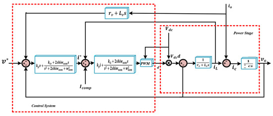
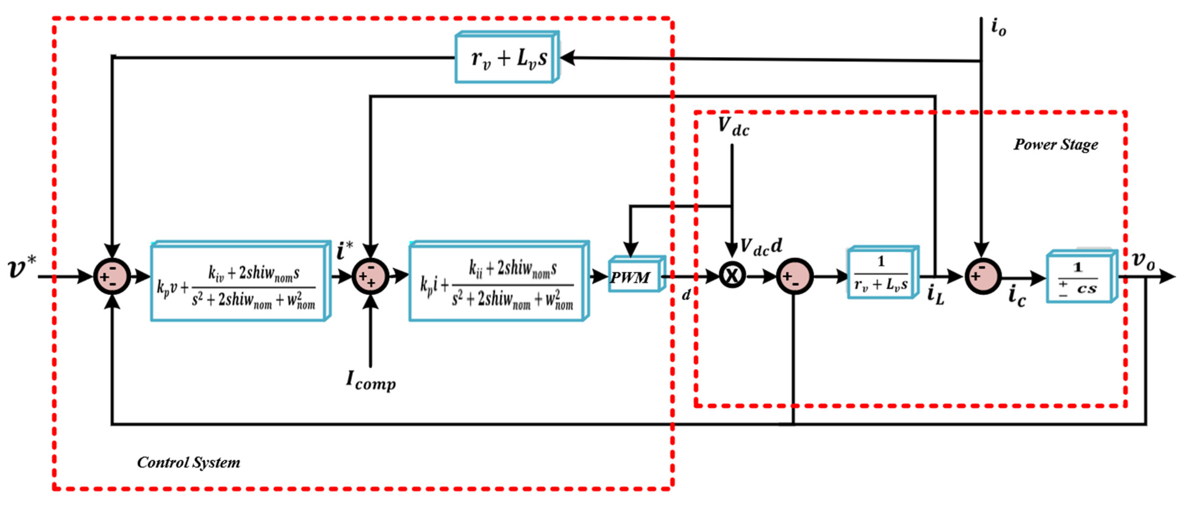
Figure 6 depicts the control architecture for inverter-based microgrids as a power stage and outlines associated control loops. It begins with a desired voltage reference, , derived from droop control equations. This reference is compared to the actual voltage to produce an error signal. This error is then managed by a control system incorporating PR controllers, which address steady-state and oscillatory discrepancies. Inputs to the control system are obtained by subtracting the output voltage and the product of from . This difference is processed by the PR controller, which is optimized with tuning parameters and by trial and error to eliminate steady-state error, while a resonant controller leverages the system’s natural frequency, to counteract specific frequency disturbances. The resultant signal is converted into a pulse width modulation (PWM) command, which regulates the power stage comprising a constant voltage source (Vdc) and filtering components like an inductor and a capacitor.
Figure 6.
Power and control stages diagram.
A current feedback loop is also integrated, where the inductor’s current is monitored and compared with the commanded compensating current . This feedback refines the PWM signal, allowing dynamic adjustments in response to load changes or system disturbances. The primary objective of this control strategy is to sustain the output voltage, at the designated reference, ensuring consistent power quality and system stability despite variations within or external to the system. Stability is further reinforced by selecting a compensation gain, , based on system analysis using transfer function techniques and pole placement methods at various gain levels. This gain is critical in Equation (7) for calculating the conductance that suppresses negative and harmonic sequences, thereby maintaining complete system stability.
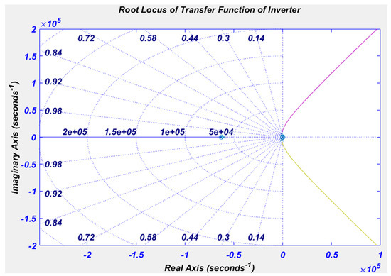
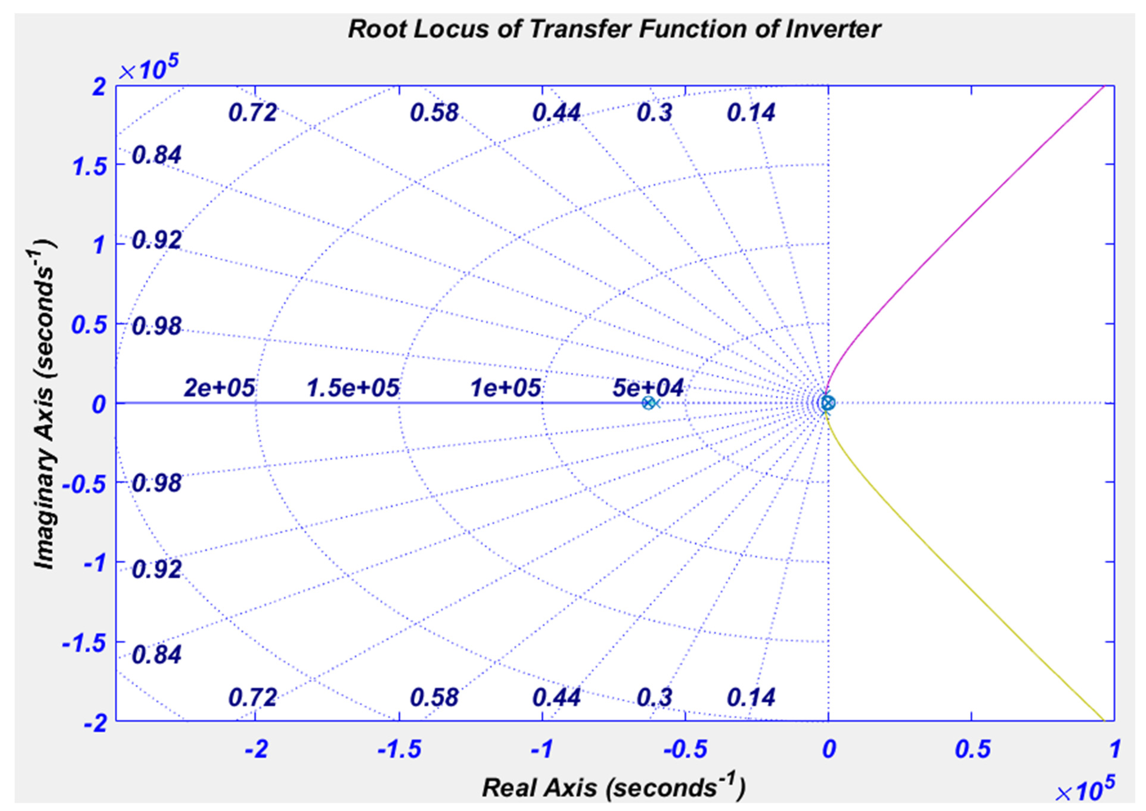
The root locus plot depicted in Figure 7 demonstrates that the system is stable, as all the poles persist in the left half of the complex plane for all gain values. No poles extend into the right half-plane, which is the region where instability could happen. The poles can shift towards more negative values along the real axis or extend into the complex plane while remaining on the left side. This behavior indicates that the system will maintain stability if the gain falls within the range examined in the plot.
Figure 7.
Root locus of the transfer function of the inverter.
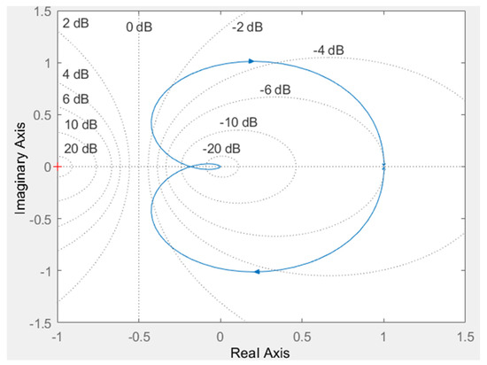
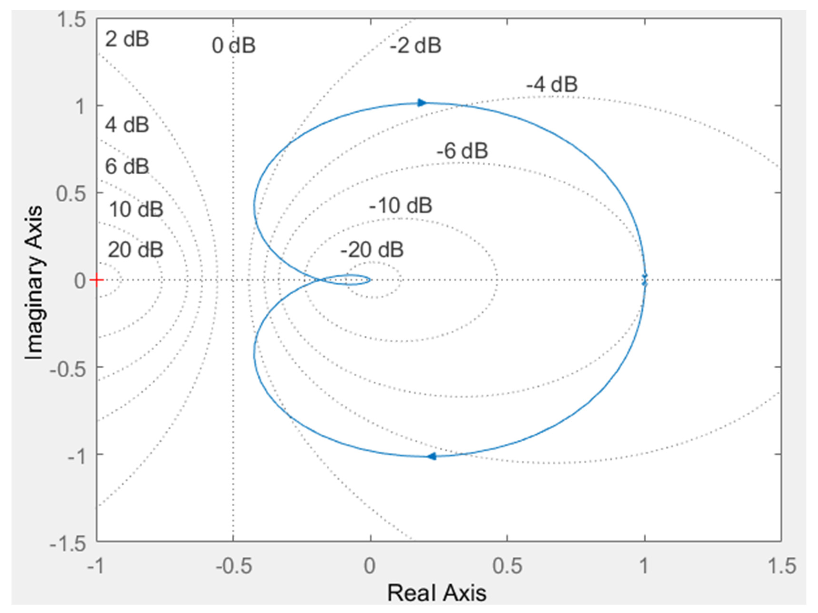
The Nyquist plot in Figure 8 exhibits a solitary loop that does not encircle the critical point,, signifying the system’s stability. The loop is significantly far from this critical point, indicating that the system has a substantial margin of stability in both gain and phase. If there are no encirclements of the point , the closed-loop system will not have any poles in the right half-plane. This further supports the conclusion that the system is stable under the given conditions. The dashed lines depict constant gain and phase contours, providing additional evidence of the system’s robustness in its response.
Figure 8.
Nyquist diagram of the inverter.
5. Simulation Results
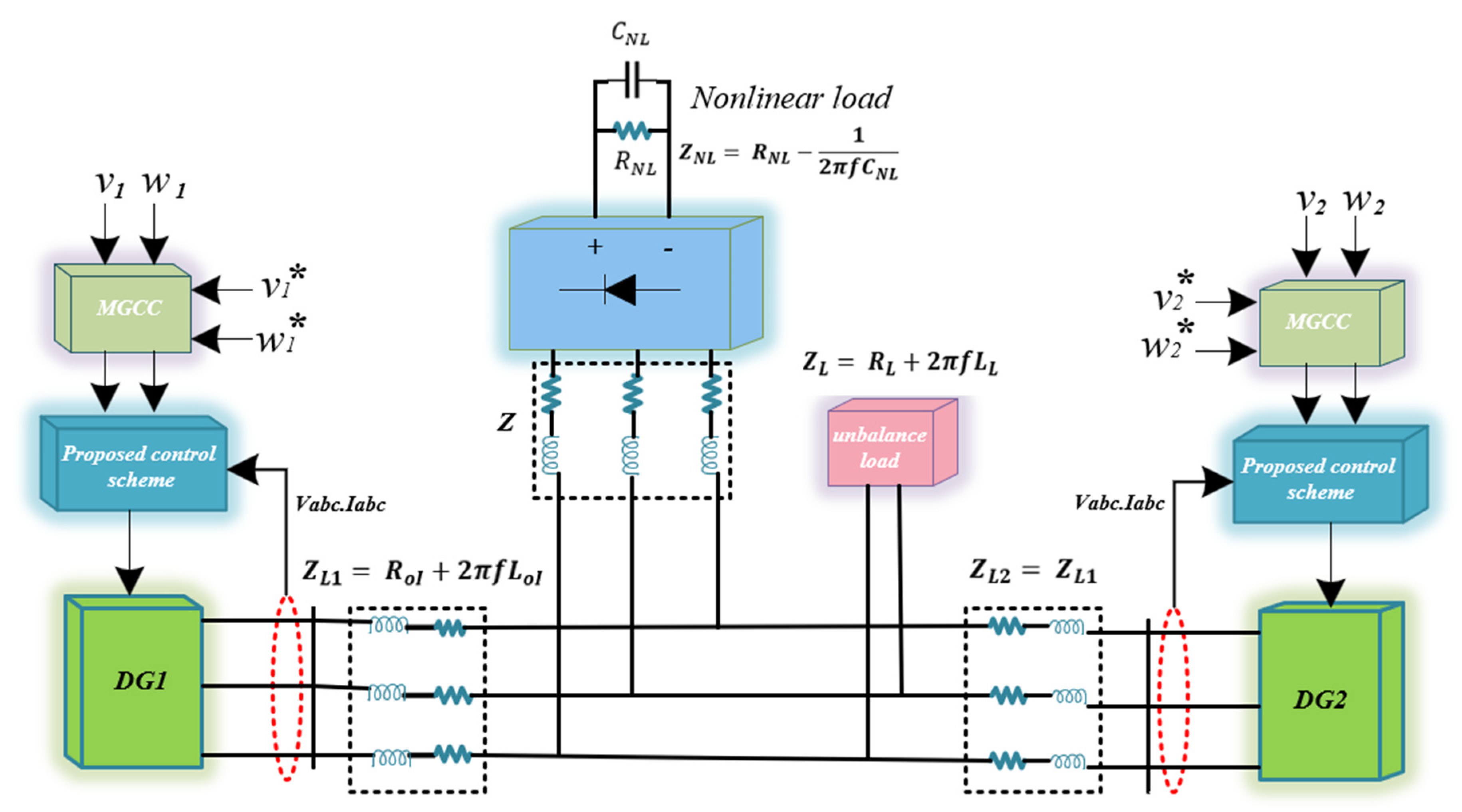
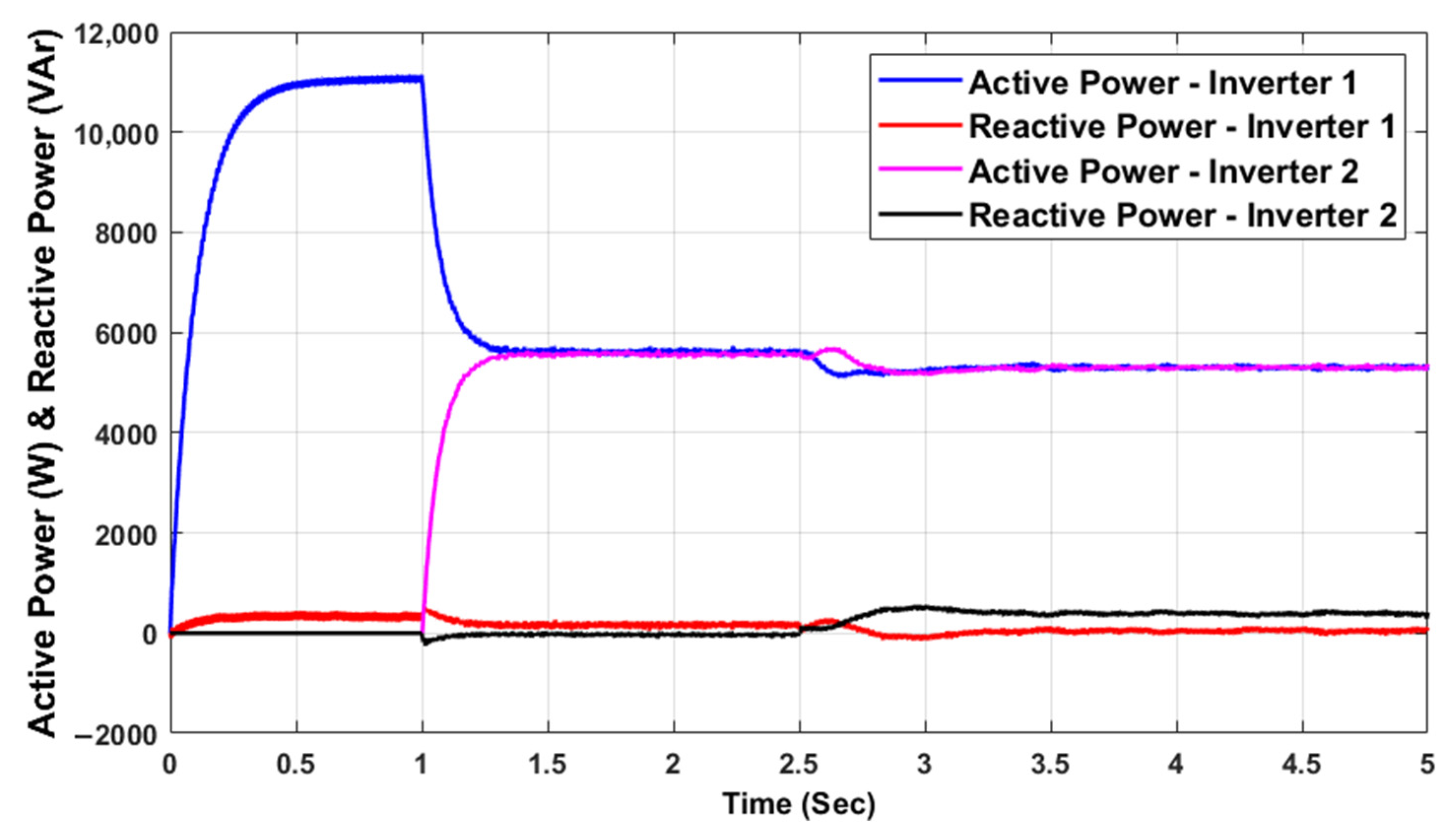
The system was tested concurrently under challenging conditions, such as plug-and-play operations with unbalanced and nonlinear loads. The system specifications and the power and control stage parameters are given in Table 1 with nonlinear and unbalanced loads. The results show that the experiment was conducted on MG composed of two DGs under different loading scenarios, including nonlinear and unbalanced resistive loads, as illustrated in Figure 9, by displaying the efficacy of the proposed control strategy when implemented on these microgrids. The performance of the proposed compensation method was tested in a plug-and-play situation, with a timeline from 0 to 1 s, where the second microgrid was deactivated, as shown in Figure 10, and the DG1 was activated during the period 0–1 s facing nonlinear and unbalanced loads with total power compensation. In this case, DG1 exclusively managed the load, and the DG2 unit was activated at 1 s, encountering unbalanced and nonlinear loads. The consumption rate of the DG1 was reduced to half due to the ideal compensation of the DG2. The energy consumption was shared between the two DGs in an ideal manner, where each DG shared half the compensation power. This led to the optimal distribution of actual power.
Table 1.
Parameters of power system and controller [16].
Figure 9.
Two microgrid systems under simulation study.
Figure 10.
Power sharing performance in microgrids under unbalanced and nonlinear load.
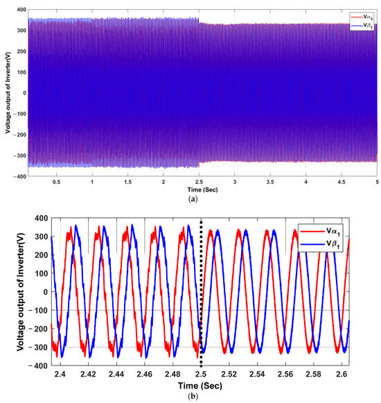
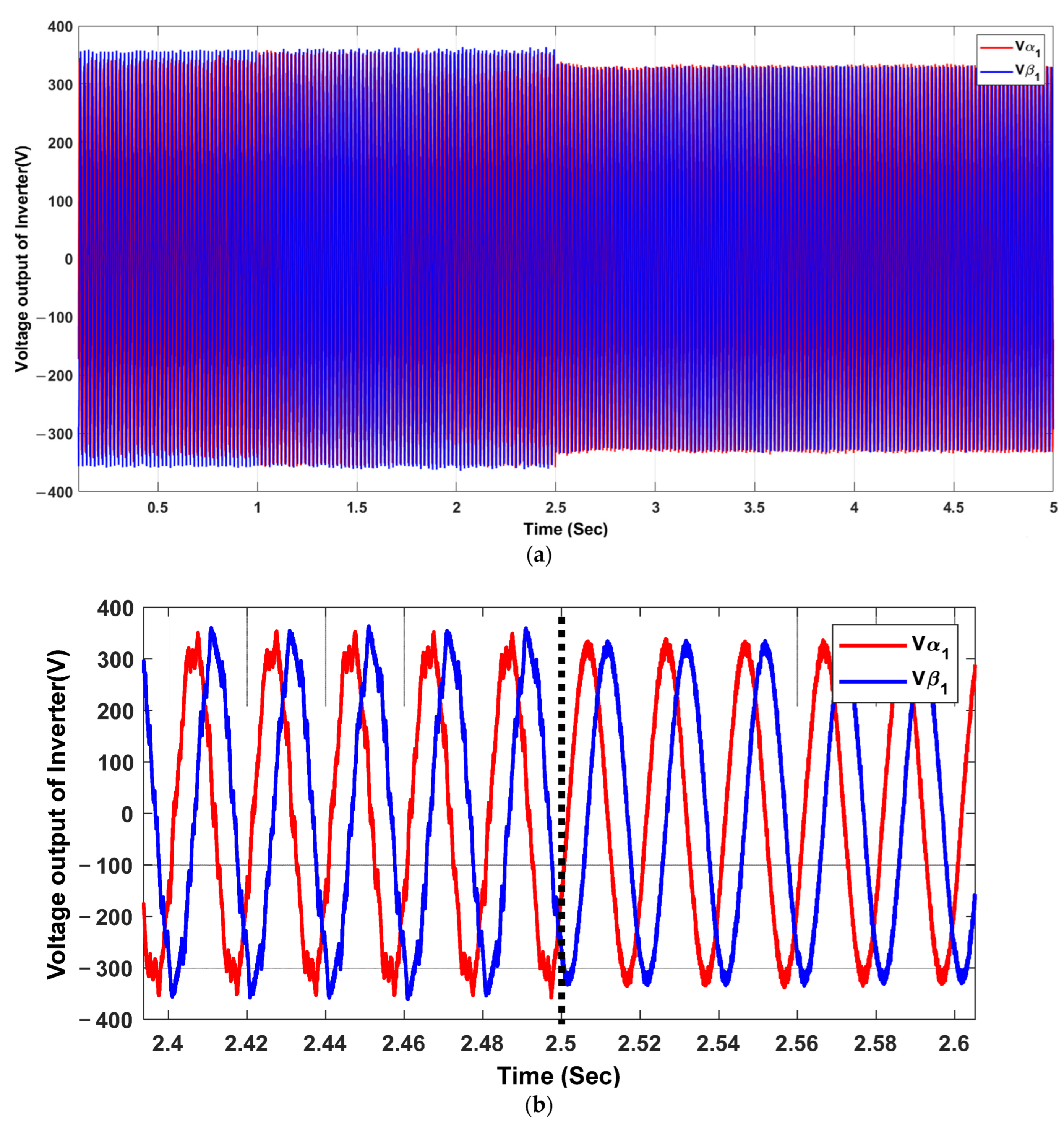
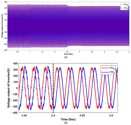
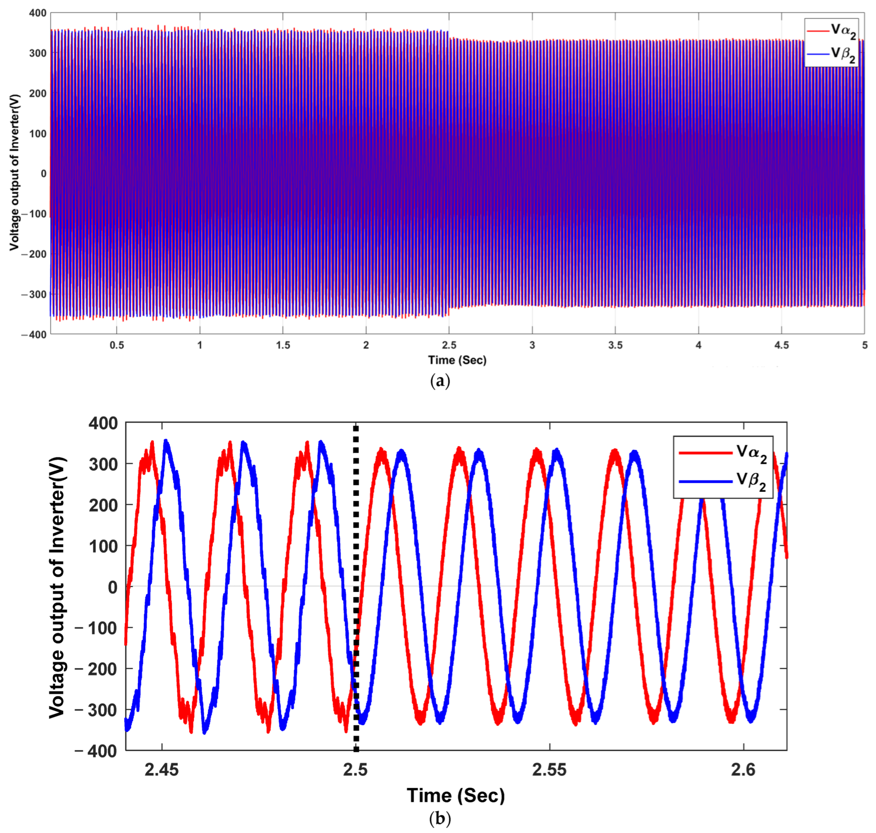
Figure 11a and Figure 12a show the effect of the proposed control strategy on recovering the output voltage and frequency deviations of the first and second inverters of DG modules with the proposed compensation strategy under unbalanced and nonlinear load conditions. It can be seen that the voltage values were quickly and successfully compensated when the control scheme was activated at 2.5 s, as shown in Figure 11b and Figure 12b. The output voltage is regulated within the islanded microgrid, eliminating deviations caused by droop control. Moreover, the primary controller recovers the voltage successfully. Figure 11 shows the voltage output of inverter 1, with a zoomed section highlighting the changes before and after activating the proposed control loop. This figure likely demonstrates the control loop’s impact on stabilizing the output voltage of the inverter, where the zoomed section provides a detailed view of how quickly and effectively the control loop responds to fluctuations, leading to a more stable voltage output. Figure 12 depicts the voltage output of inverter 2, with a similar zoomed-in section as in Figure 11. This figure would compare and contrast with inverter 1’s performance, indicating how both inverters behave under the same control conditions. The effectiveness of the control loop in maintaining voltage stability across different inverters can be analyzed here.
Figure 11.
The proposed compensation method will be performed at 2.5 s in an electrical network with an unbalanced and nonlinear load. (a) Voltage output of inverter 1, (b) zoomed section before and after activating the proposed control loop.
Figure 12.
Performance of the proposed compensation method at 2.5 s in an electrical network with unbalanced load and nonlinear load (a) The voltage output of inverter 2, (b) zoomed section before and after activating the proposed control loop.
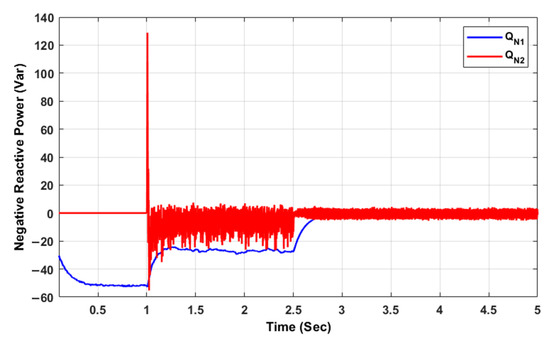
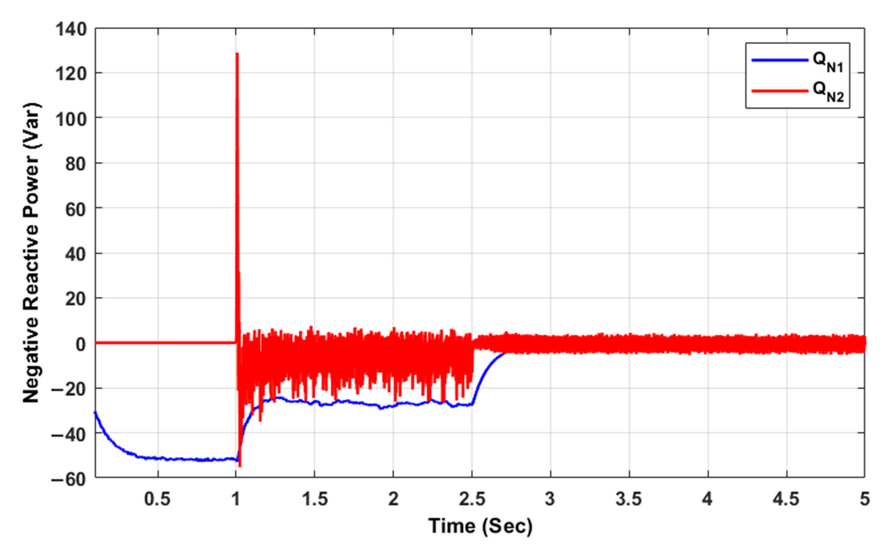
Figure 13 shows the negative reactive power value from (0–2.5 s) for DG1 DG2 and how it was reduced or treated optimally at (2.5 s) to eliminate the negative sequence to reach zero. This figure highlights the control loop’s ability to detect and correct imbalances in the power system, reducing the negative sequence to achieve a more balanced and efficient power flow.
Figure 13.
Negative sequence reactive powers.
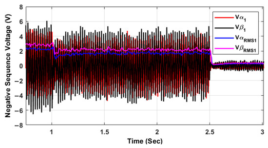
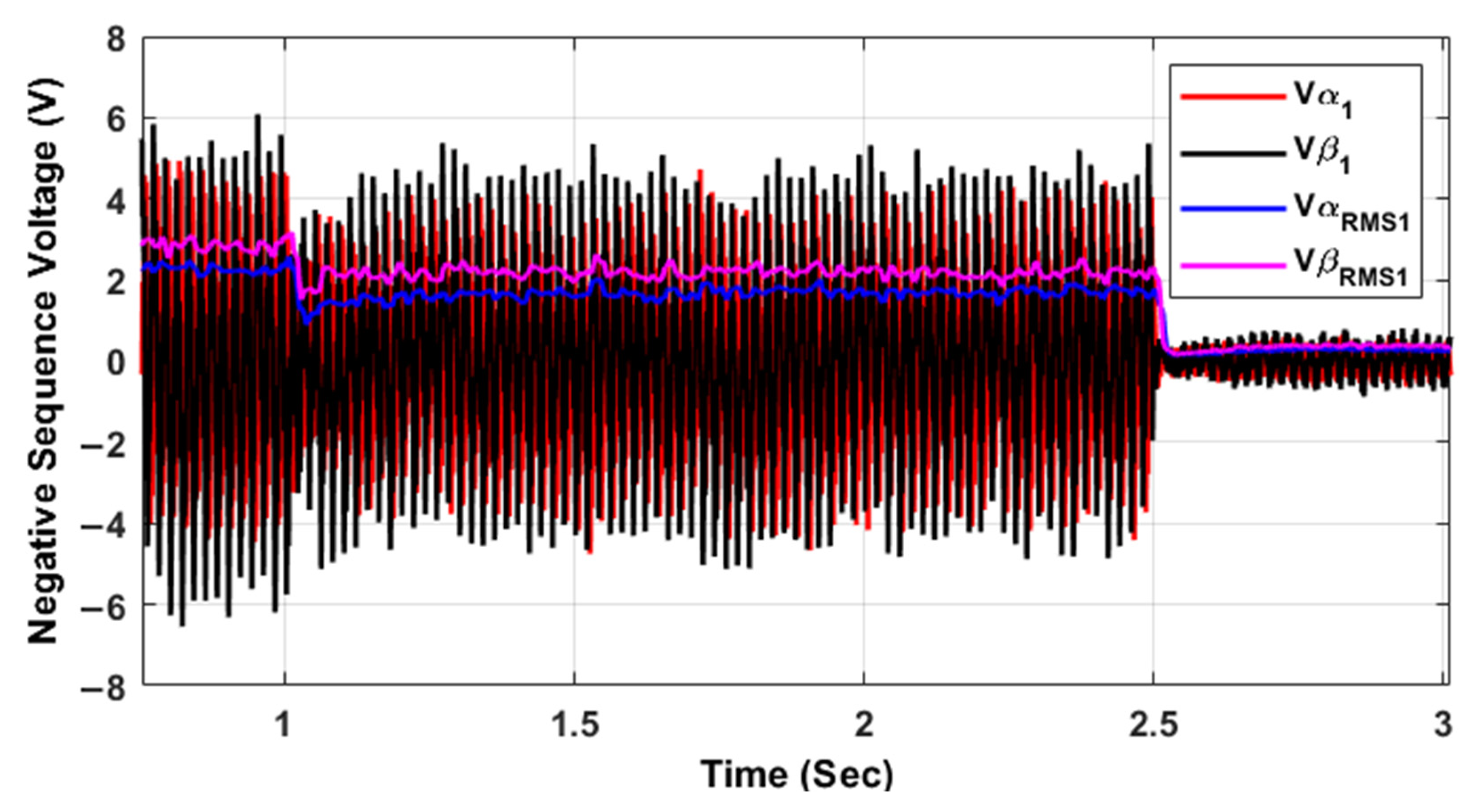
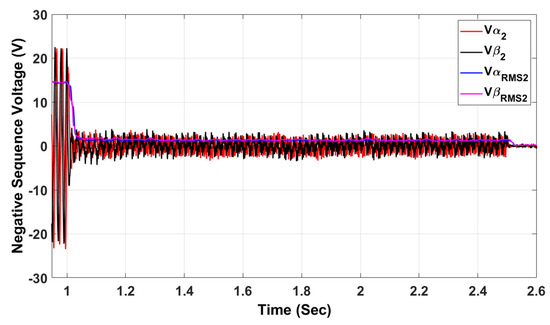
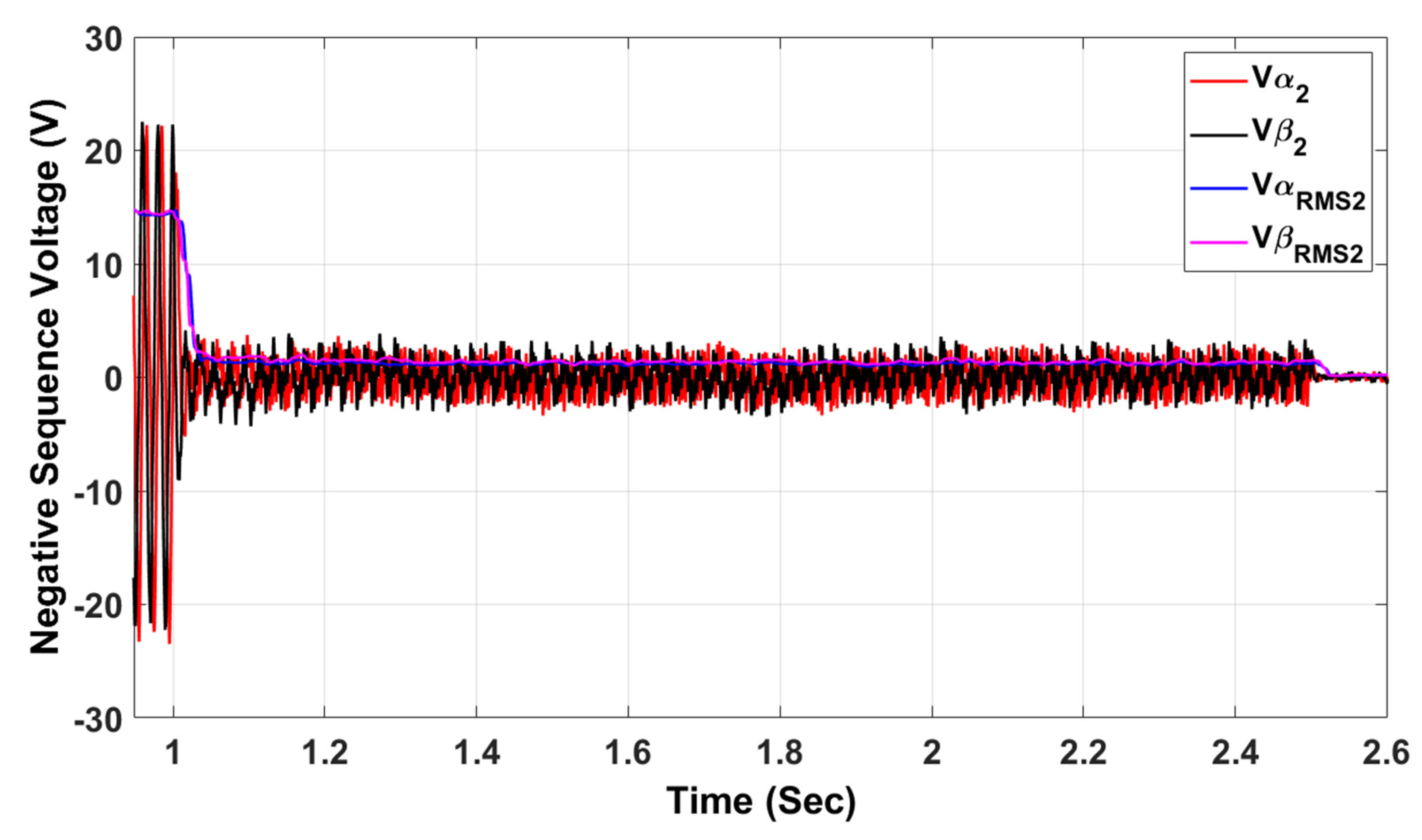
Figure 14 and Figure 15 show the negative voltage from (0–2.5 s) due to nonlinear loads for each inverter. At (2.5 s), the proposed control action was activated to cancel the negative voltage in the first and second inverters and bring it closer to zero to obtain the best stable voltage. It has been observed in Figure 13, Figure 14 and Figure 15 that the control action reduces the negative sequence without eliminating it. Subsequently, at 2.5 s, harmonic compensation is added to the balanced voltage, resulting in the complete cancellation of both harmonics and the negative sequence, as illustrated in the exact figures.
Figure 14.
Negative sequence voltage of inverter 1.
Figure 15.
Negative sequence voltage of inverter 2.
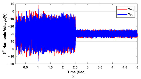
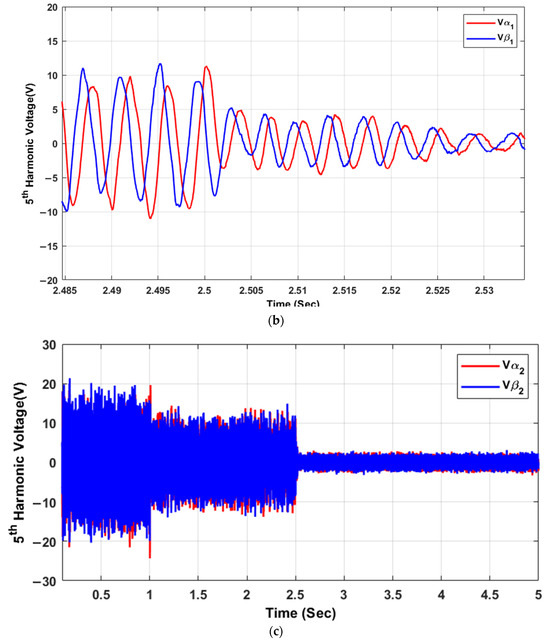
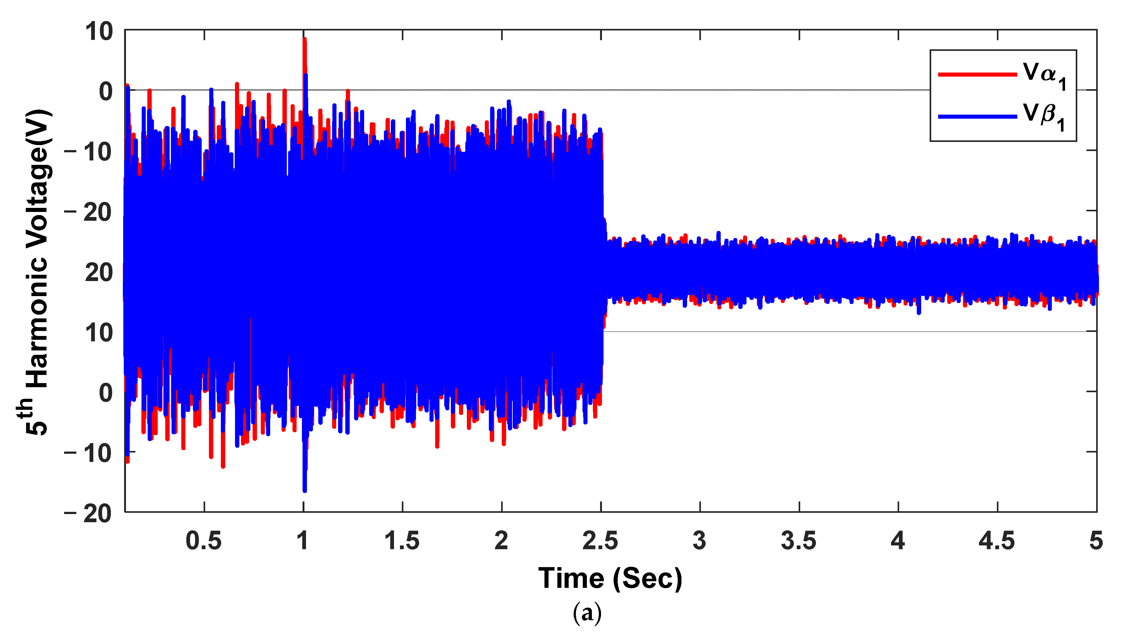
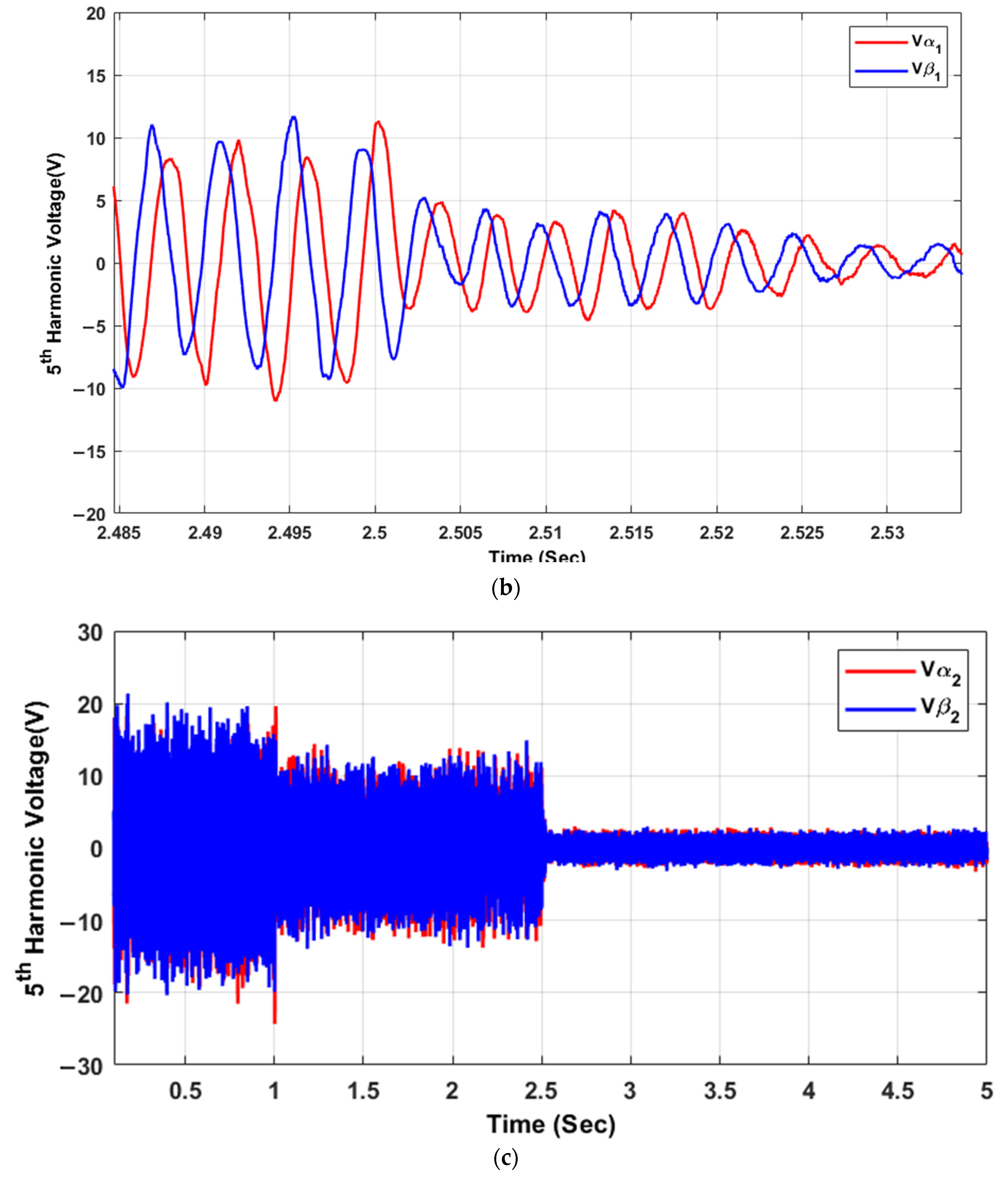
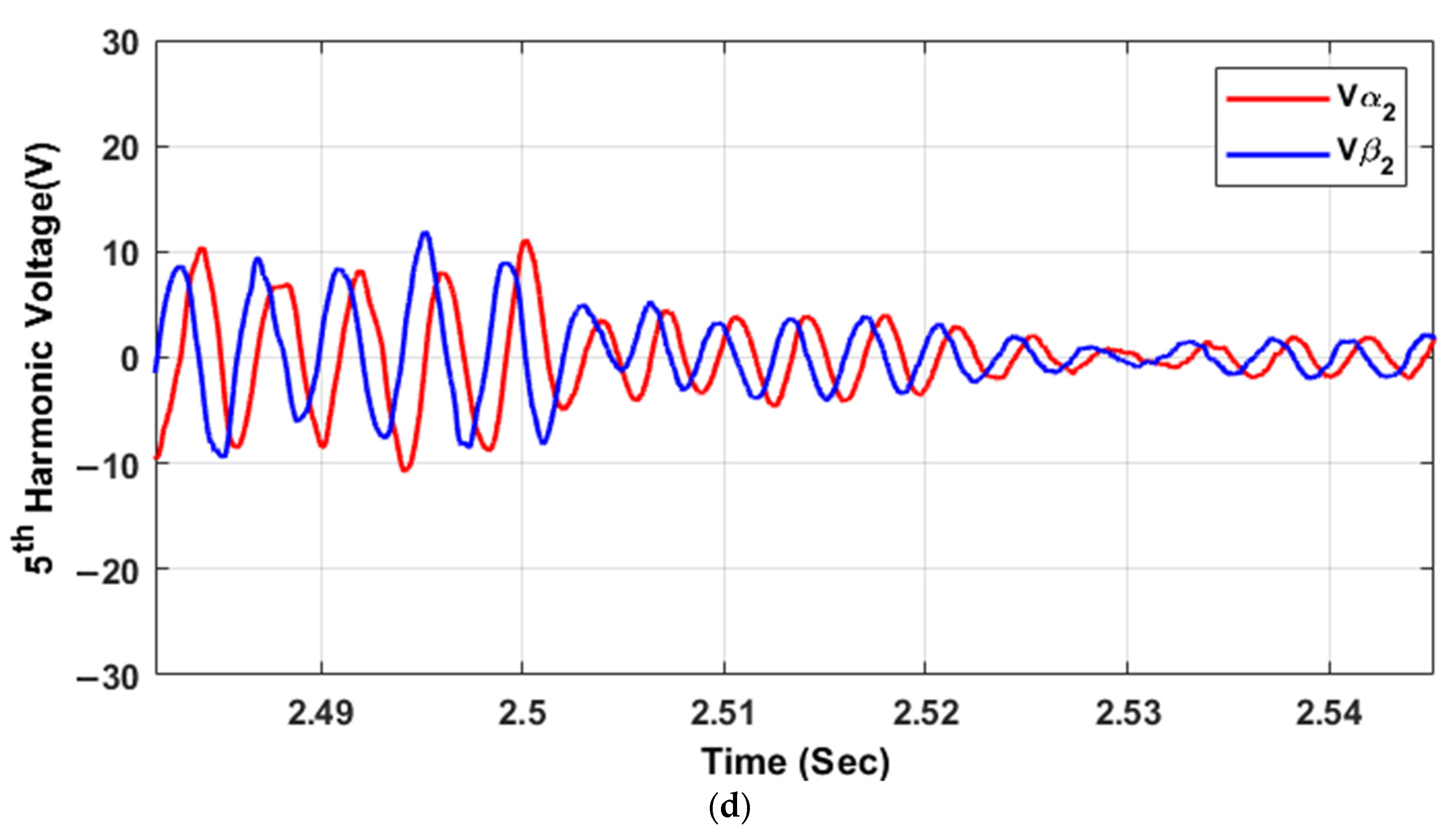
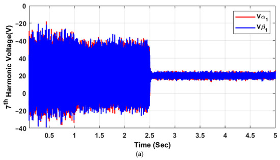
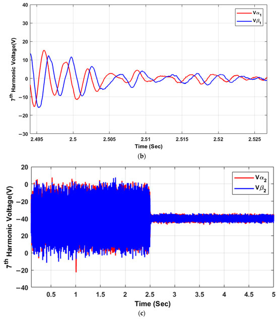
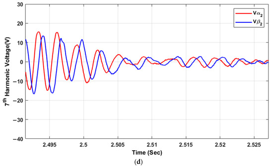
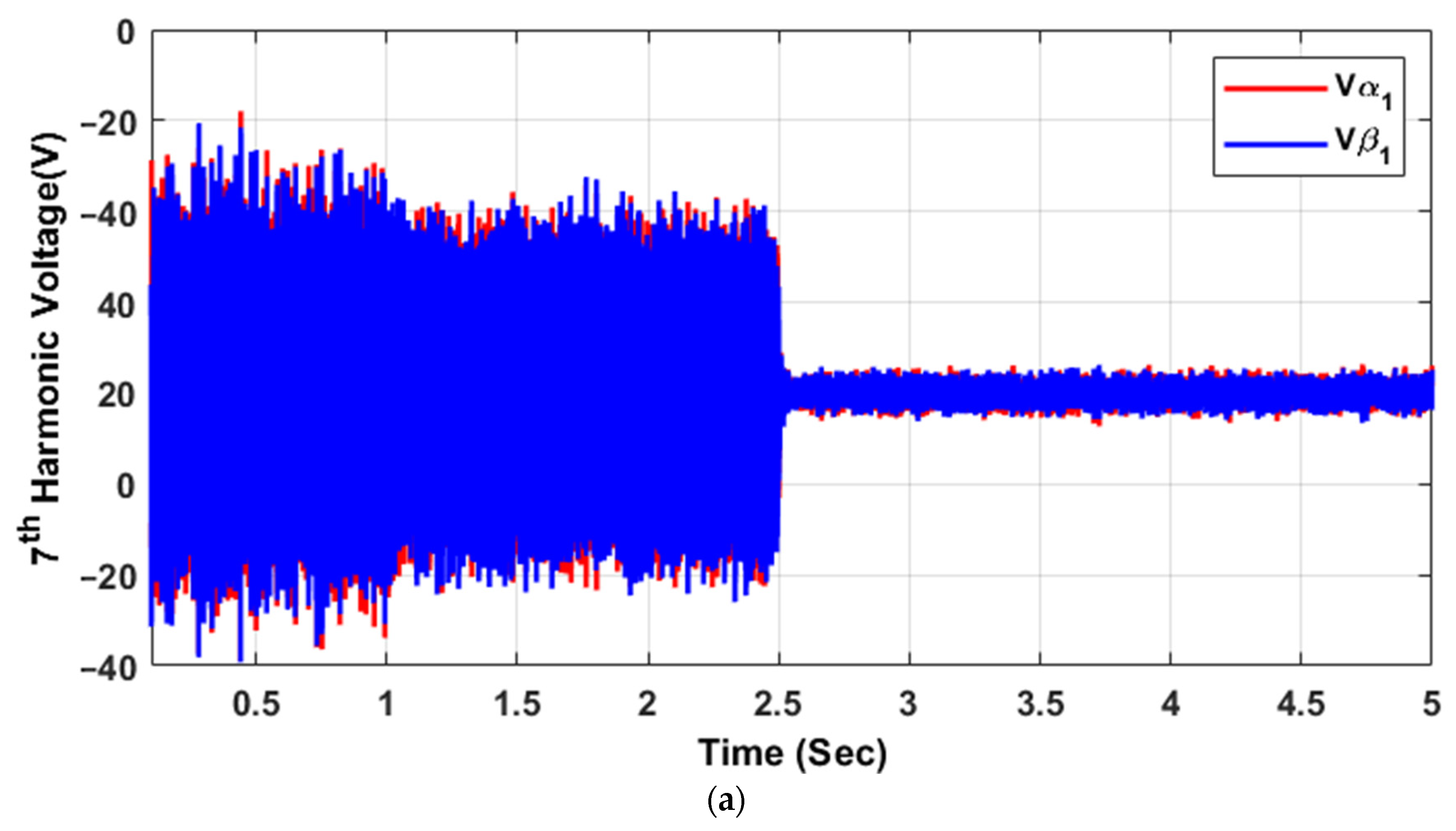
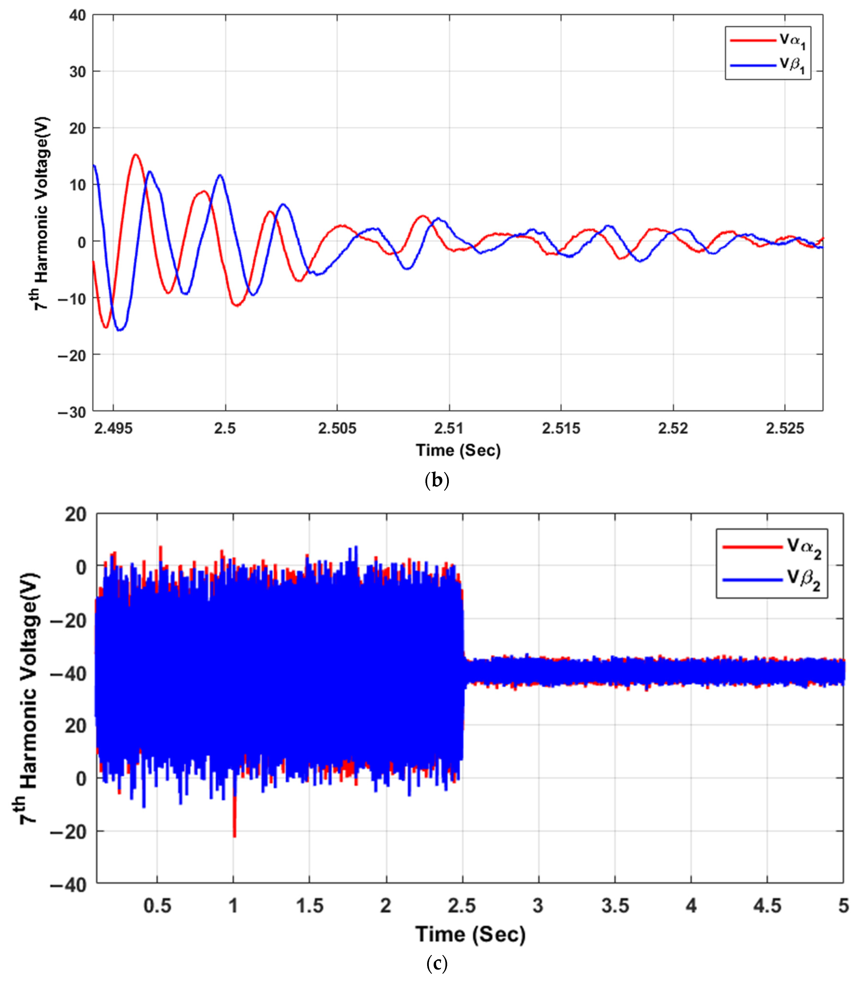
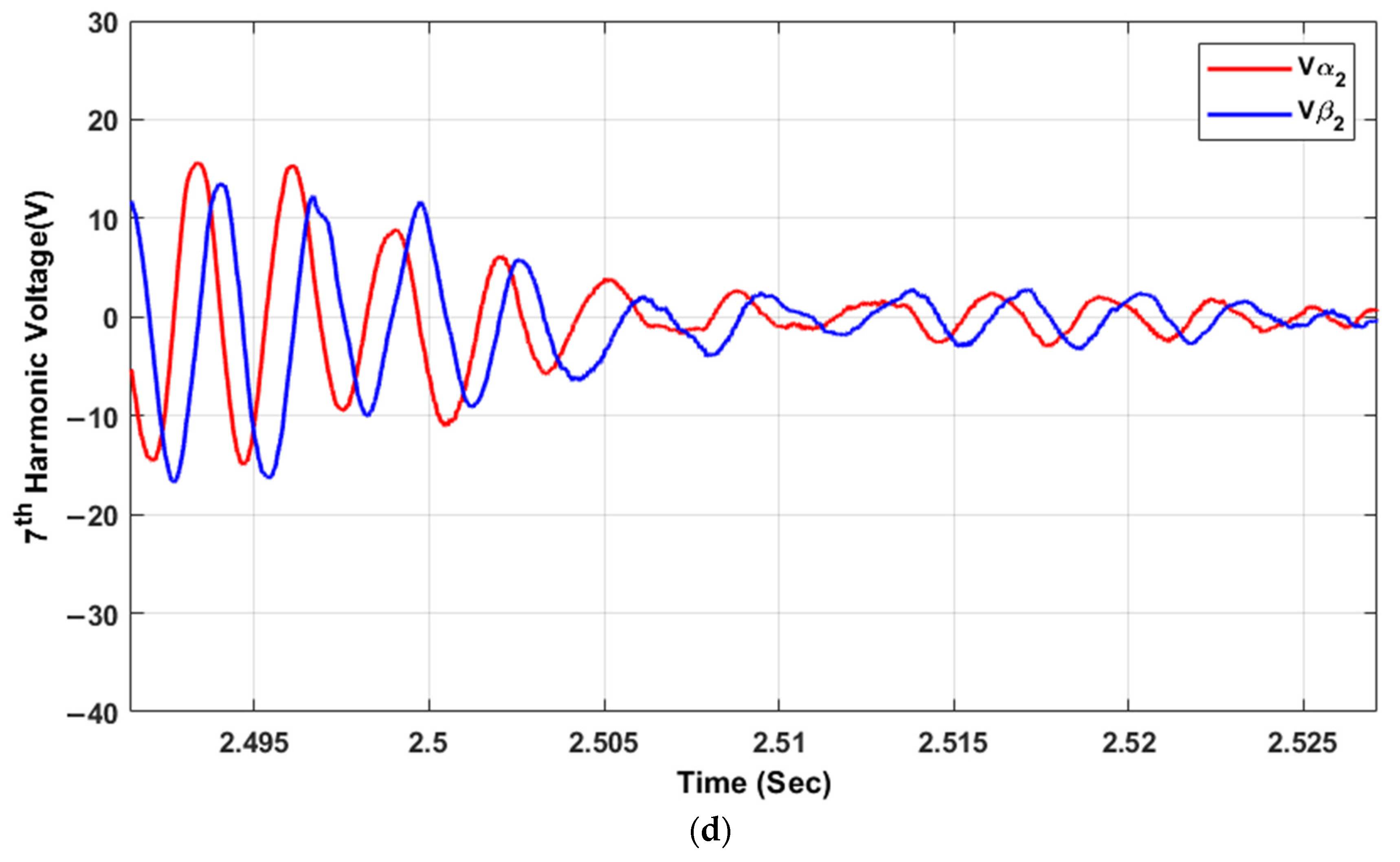
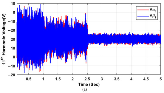
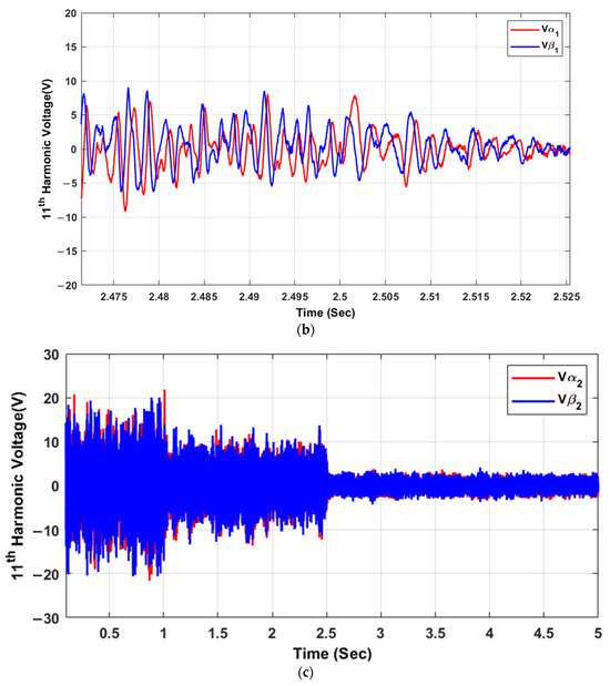
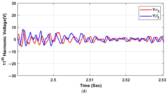
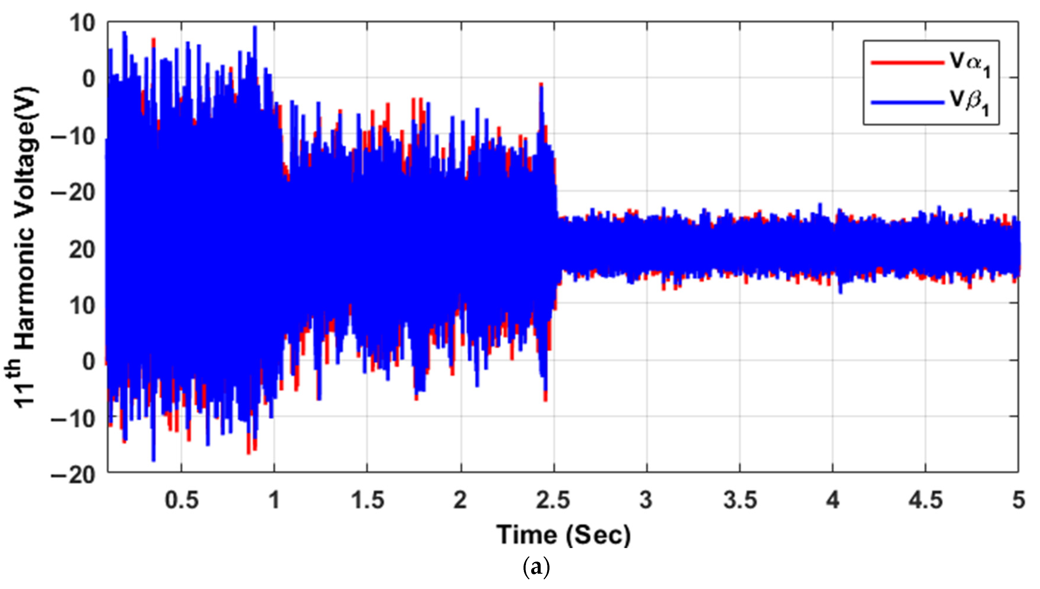
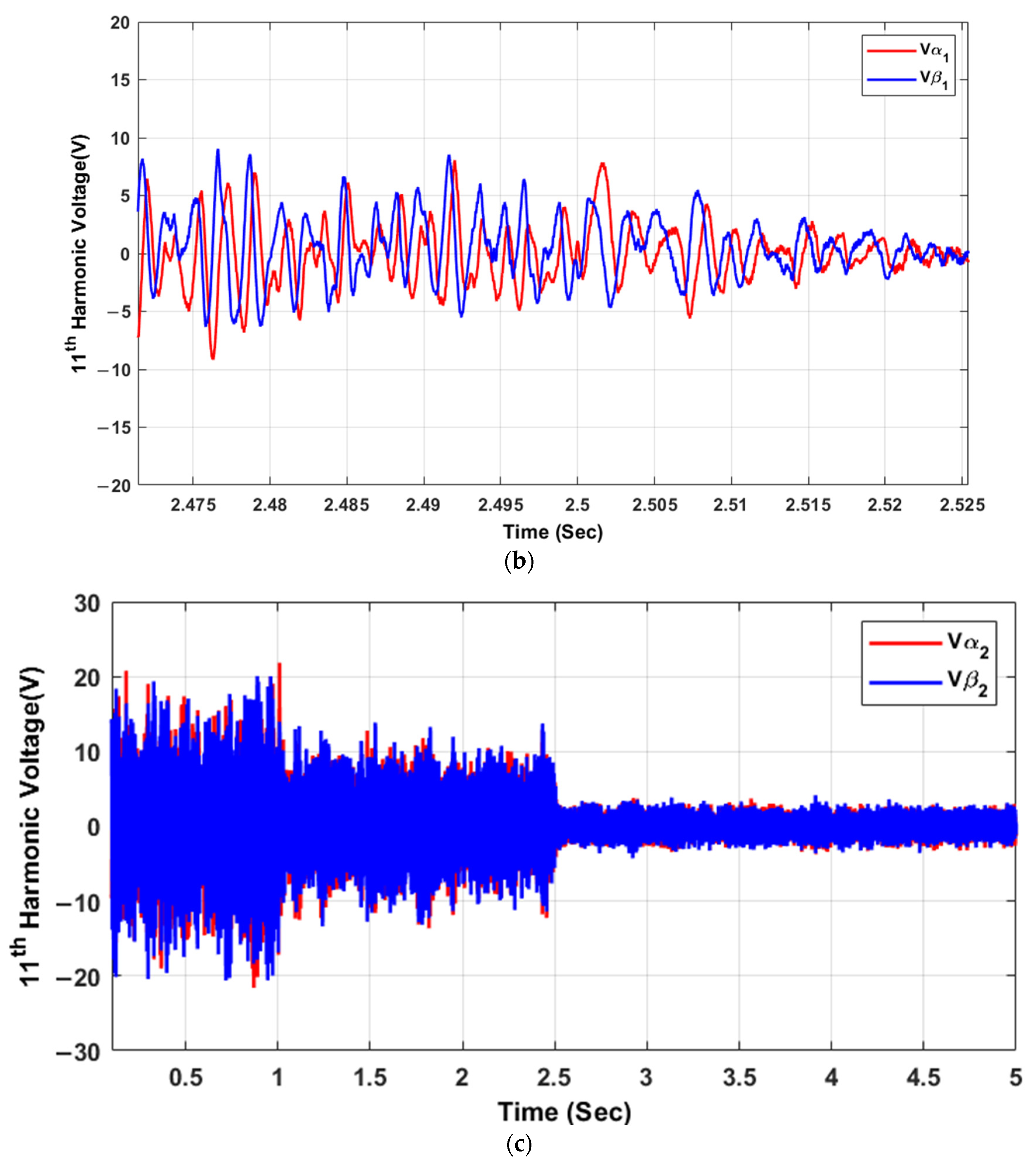
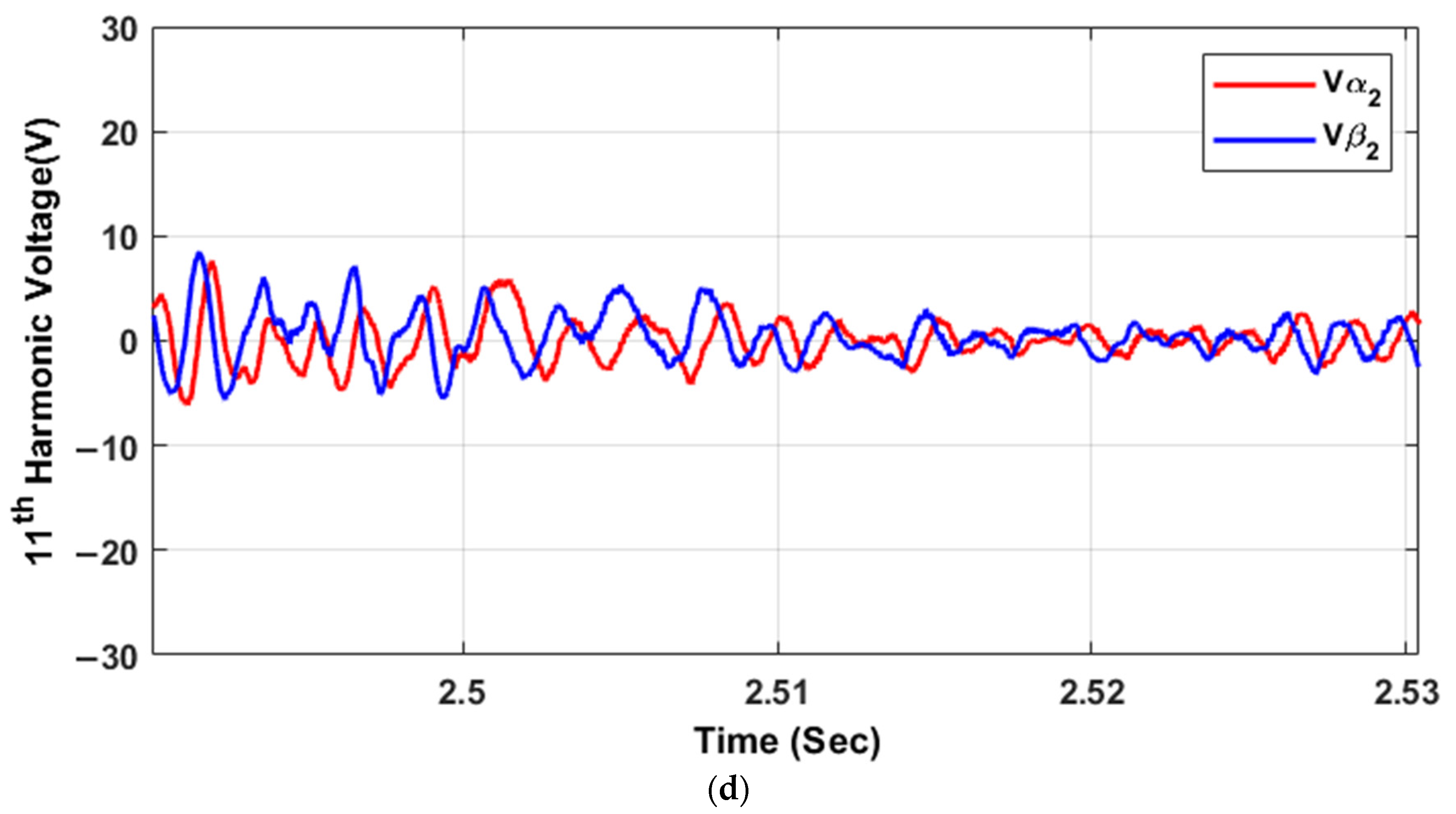
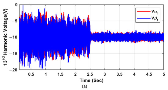
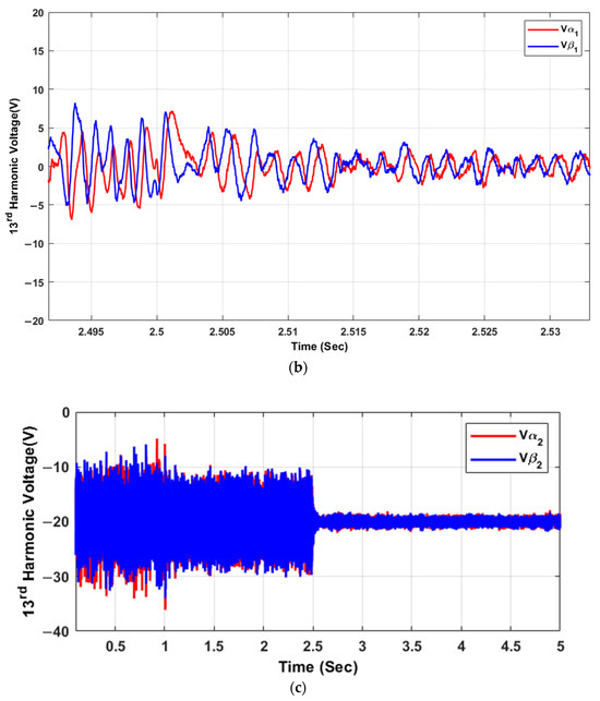
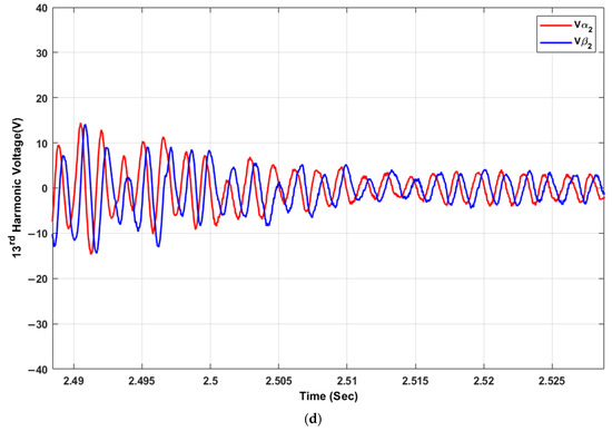
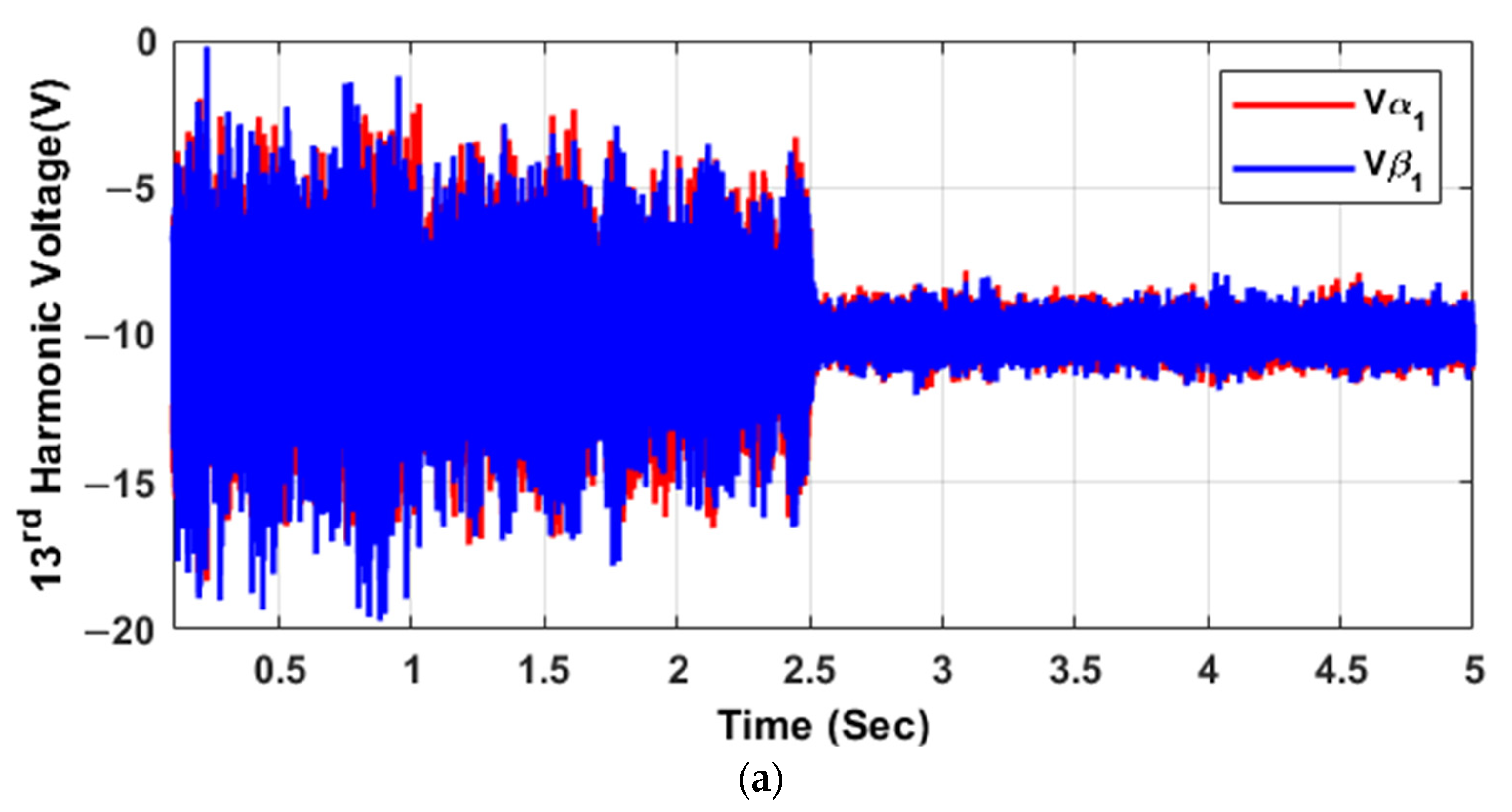
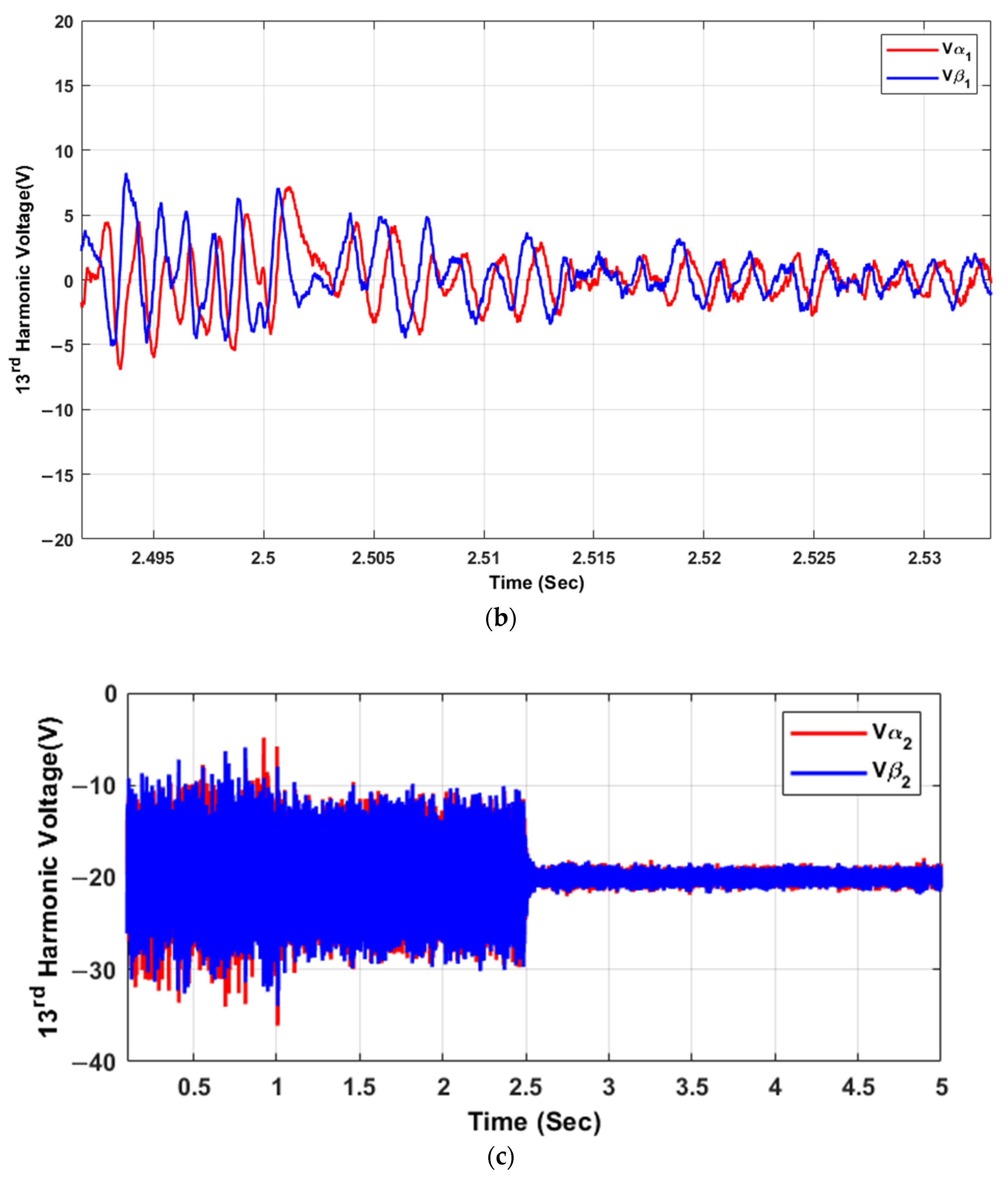
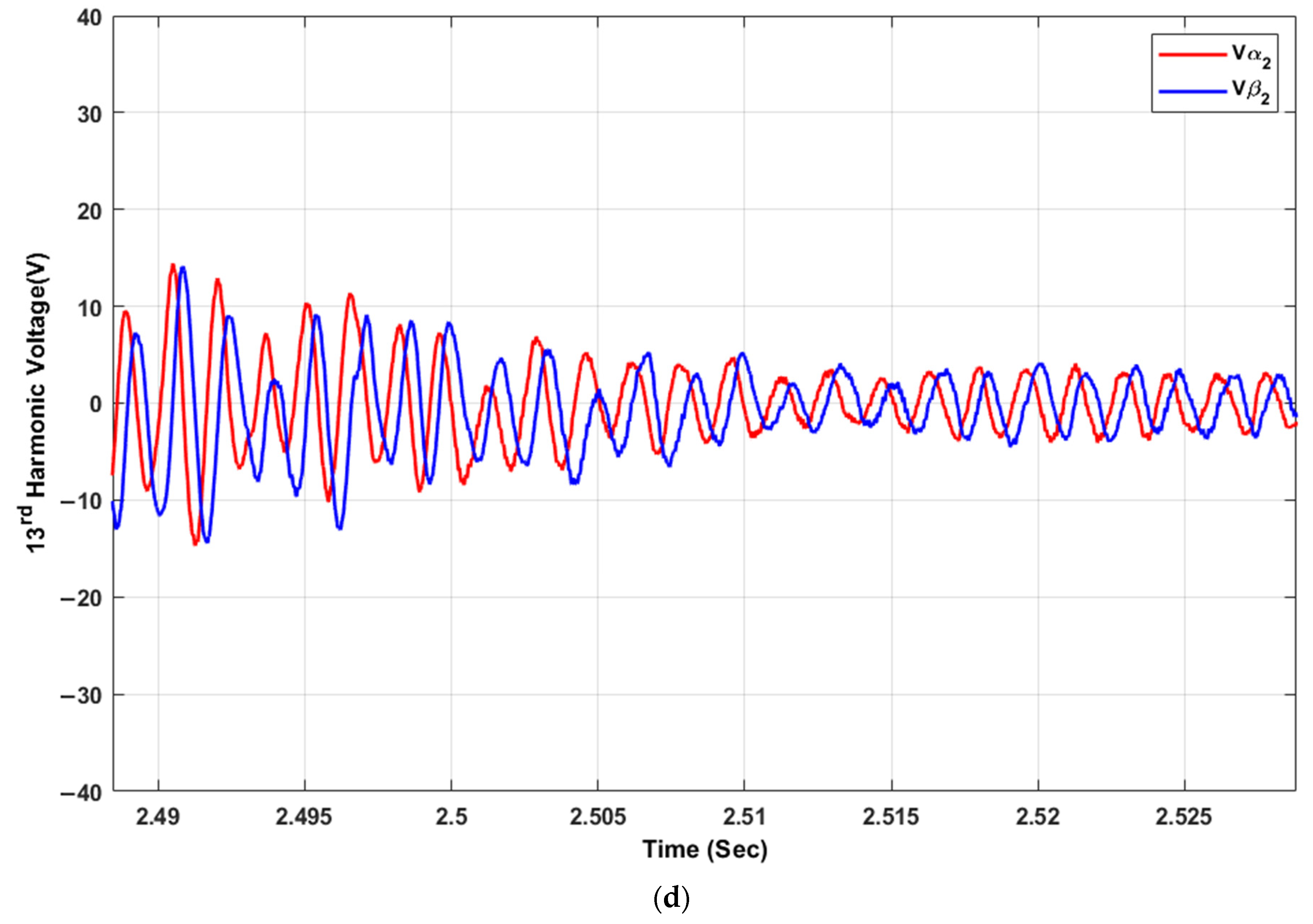
The findings indicate that the implemented control loop effectively regulates the output from two inverters, specifically targeting negative sequence and harmonic distortions. The observations revealed a notable reduction in negative reactive power and harmonic sequence voltage when the control loop was activated, as depicted in Figure 16, Figure 17, Figure 18 and Figure 19. Moreover, the application of harmonic compensation beyond 2.5 s completely neutralizes negative sequences and harmonics, illustrating the control loop’s capacity to ensure voltage stability and enhance power quality, as shown in these figures. Figure 16, Figure 17, Figure 18 and Figure 19 elaborate on the individual harmonic voltages (5th, 7th, 11th, and 13th harmonics) for the inverters. These figures presumably demonstrate the control loop’s effectiveness in eliminating or mitigating specific harmonic frequencies, affirming the system’s ability to manage diverse harmonic distortions and thus improve overall power quality and system functionality. The thorough examination provided by Figure 16, Figure 17, Figure 18 and Figure 19 emphasizes the effective reduction of negative-sequence voltages and different harmonic intensities (5th, 7th, 11th, and 13th), highlighting the proposed system’s strong performance in promoting power system stability and efficiency.
Figure 16.
5th Harmonic voltage (a,b) inverter 1, (c,d) inverter 2.
Figure 17.
7th harmonic voltage (a,b) inverter 1, (c,d) inverter 2.
Figure 18.
11th harmonic voltage (a,b) inverter 1, (c,d) inverter 2.
Figure 19.
13rd harmonic voltage (a,b) inverter 1, (c,d) inverter 2.
6. Comparing the State of the Art with Control Scheme
Table 2 compares various studies on MG compensators, focusing on their effectiveness in addressing unbalanced voltage and harmonics and their positioning within the control structure. The studies [9,10,11,14,27,28] primarily target unbalanced voltage compensation without addressing harmonics or achieving mitigation, and they are situated at different control layers, namely primary, secondary, and tertiary. In contrast, studies [12,13] tackle unbalanced voltage and harmonics but fail to achieve complete cancellation, operating at the primary and secondary layers. The proposed method stands out by compensating for both unbalanced voltage and harmonics at the primary layer and uniquely achieves mitigation. This comprehensive approach to power quality management in microgrids signifies an advanced step in ensuring the stability and efficiency of microgrid operations, distinguishing the proposed method from previous studies.
Table 2.
Comparison of the proposed control scheme with related work.
7. Conclusions
This paper presents a novel control strategy that selectively targets harmonics and negative sequences using a multi-SOGI-based approach for complete elimination. This approach effectively manages the output from two inverters and mitigates negative-sequence distortions and harmonics in the PCC. Through detailed simulation, the study shows a significant reduction in negative reactive power and sequence voltage when the control loop is started. After activation, the harmonic compensation effectively eliminates negative sequences and harmonics, which leads to voltage stability and improved power quality, as we observed in the recovery of the output voltage and frequency deviation of the first and second inverters, as well as the response speed of voltage compensation at 2.5 s simultaneously, which proves the effectiveness of the control loop in maintaining stable voltage. The study also shows the ability to reduce negative reactive power between 0–2.5 s to eliminate negative sequences and negative voltage between the first and second inverters to zero and correct the imbalances in the power system.
Moreover, the results show that applying harmonic compensation after 2.5 s neutralizes the individual harmonic voltages. In addition, incorporating a central secondary controller is vital to maintaining stable voltage and frequency amplitude and improving the microgrid’s reliability. This strategy was implemented on the MATLAB/Simulink platform and rigorously tested under various challenging scenarios, including unbalanced and nonlinear loads, demonstrating the accuracy of the control loop in eliminating specific harmonic frequencies, such as 5th, 7th, 11th, and 13th, thus proving its ability to manage a wide range of harmonic distortions. This efficiency in reducing harmonics and negative sequences improves power quality, system efficiency, and stability. Future research will focus on applying this approach to small multi-node grids in remote locations to demonstrate the robustness and effectiveness of the proposed scheme.
The essential results of this study are voltage stability and enhanced power quality through neutralizing sequence and harmonics by adding harmonic compensation to the balanced voltage, which leads to the complete cancellation of harmonics and negative sequence.
Author Contributions
Conceptualization, A.G.S.A.-s. and C.R.-C.; Methodology, E.R.-C. and C.R.-C.; Writing—original draft preparation, A.G.S.A.-s.; Editing, C.R.-C.; Supervision, E.R.-C. and C.R.-C.; Simulation, A.G.S.A.-s.; Formatting, C.R.-C.; Funding Acquisition, E.R.-C. and C.R.-C.; Validation, A.G.S.A.-s. and C.R.-C. All authors have read and agreed to the published version of the manuscript.
Funding
Authors want to acknowledge to the support by the Grant PID2022-137345OA-I00 funded by MCIN/AEI/10.13039/501100011033 and “ERDF A way of making Europe”.
Data Availability Statement
Data is contained within the article.
Conflicts of Interest
The authors declare that the research was conducted in the absence of any commercial or financial relationships that could be construed as a potential conflict of interest. The authors declare no conflict of interest.
References
- Uddin, M.; Mo, H.; Dong, D.; Elsawah, S.; Zhu, J.; Guerrero, J.M. Microgrids: A Review, Outstanding Issues, and Future Trends. Energy Strategy Rev. 2023, 49, 101127. [Google Scholar] [CrossRef] [Scilit]
- Yaqoob, M. Design Control and Power Management of Small Satellite Microgrids. Ph.D. Thesis, Aalborg University, Aalborg, Denmark, 2022. [Google Scholar] [CrossRef] [Scilit]
- Swadi, M.; Kadhim, D.J.; Salem, M.; Tuaimah, F.M.; Majeed, A.S.; Alrubaie, A.J. Investigating and predicting the role of photovoltaic, wind, and hydrogen energies in sustainable global energy evolution. Glob. Energy Interconnect. 2024, 7, 429–445. [Google Scholar]
- Göransson, M.; Larsson, N.; Tuan, L.A.; Steen, A.D. Cost-Benefit Analysis of Battery Storage Investment for Microgrid of Chalmers University Campus Using µ-Opf Framework. In Proceedings of the 2017 IEEE Manchester PowerTech, Manchester, UK, 18–22 June 2017. [Google Scholar]
- Al-Salloomee, A.G.S.; Romero-Cadaval, E.; Roncero-Clemente, C.; Swadi, M. Efficient Control Scheme for Compensating Voltage Unbalance and Harmonics in Islanded Microgrid Inverters. In Proceedings of the 2024 IEEE 22nd Mediterranean Electrotechnical Conference (MELECON), Porto, Portugal, 25–27 June 2024; pp. 574–579. [Google Scholar] [CrossRef] [Scilit]
- Ansari, S.; Zeinoddini-Meymand, H.; Niknam, T. Optimal Operation of Ac and Dc Hybrid Microgrid in Two Management Scenarios. In Proceedings of the ICEE 2019—27th Iranian Conference On Electrical Engineering, Yazd, Iran, 30 April–2 May 2019; Institute of Electrical and Electronics Engineers Inc.: Piscataway, NJ, USA; pp. 856–862. [Google Scholar] [CrossRef] [Scilit]
- Lenhart, S.; Araújo, K. Microgrid Decision-Making by Public Power Utilities in The United States: A Critical Assessment of Adoption and Technological Profiles. Renew. Sustain. Energy Rev. 2021, 139, 110692. [Google Scholar] [CrossRef] [Scilit]
- Alajrash, B.H.; Salem, M.; Swadi, M.; Senjyu, T.; Kamarol, M.; Motahhir, S. A comprehensive review of FACTS devices in modern power systems: Addressing power quality, optimal placement, and stability with renewable energy penetration. Energy Rep. 2024, 11, 5350–5371. [Google Scholar]
- Savaghebi, M.; Jalilian, A.; Vasquez, J.C.; Guerrero, J.M. Autonomous Voltage Unbalance Compensation in An Islanded Droop-Controlled Microgrid. IEEE Trans. Ind. Electron. 2013, 60, 1390–1402. [Google Scholar] [CrossRef] [Scilit]
- Meng, L.; Tang, F.; Savaghebi, M.; Vasquez, J.C.; Guerrero, A.J.M. Tertiary Control of Voltage Unbalance Compensation for Optimal Power Quality in Islanded Microgrids. IEEE Trans. Energy Convers. 2014, 29, 802–815. [Google Scholar] [CrossRef] [Scilit]
- Camacho, A.; Castilla, M.; Miret, J.; Velasco, M.; Guzman, R. Positive-Sequence Voltage Control, Full Negative-Sequence Cancellation, and Current Limitation for Static Compensators. IEEE J. Emerg. Sel. Top. Power Electron. 2021, 9, 6613–6623. [Google Scholar] [CrossRef] [Scilit]
- Liu, Q.; Tao, Y.; Liu, X.; Deng, Y.; He, X. Voltage Unbalance and Harmonics Compensation for Islanded Microgrid Inverters. IET Power Electron. 2014, 7, 1055–1063. [Google Scholar] [CrossRef] [Scilit]
- Han, Y.; Shen, P.; Zhao, X.; Guerrero, J.M. An Enhanced Power Sharing Scheme for Voltage Unbalance and Harmonics Compensation in An Islanded Ac Microgrid. IEEE Trans. Energy Convers. 2016, 31, 1037–1050. [Google Scholar] [CrossRef] [Scilit]
- Vijay, A.S.; Doolla, S.; Chandorkar, M.C. Unbalance Mitigation Strategies in Microgrids. IET Power Electron. 2020, 13, 1687–1710. [Google Scholar] [CrossRef] [Scilit]
- Shahgholian, G. A Brief Review on Microgrids: Operation, Applications, Modeling, and Control. Int. Trans. Electr. Energy Syst. 2021, 31, 1–28. [Google Scholar] [CrossRef] [Scilit]
- De Andrade, F.; Castilla, M.; Bonatto, B.D. Springer Briefs in Energy Basic Tutorial on Simulation of Microgrids Control Using Matlab® & Simulink® Software. Available online: http://www.springer.com/series/8903 (accessed on 4 March 2020).
- Numminen, S.; Lund, P.D. Evaluation of The Reliability of Solar Micro-Grids in Emerging Markets—Issues and Solutions. Energy Sustain. Dev. 2019, 48, 34–42. [Google Scholar] [CrossRef] [Scilit]
- Mirsaeidi, S.; Dong, X.; Said, D.M. Towards Hybrid Ac/Dc Microgrids: Critical Analysis and Classification of Protection Strategies. Renew. Sustain. Energy Rev. 2018, 90, 97–103. [Google Scholar] [CrossRef] [Scilit]
- Seane, T.B.; Samikannu, R.; Bader, T. A Review of Modeling and Simulation Tools for Microgrids Based on Solar Photovoltaics. Front. Energy Res. 2022, 10, 1–20. [Google Scholar] [CrossRef] [Scilit]
- Chandak, S.; Bhowmik, P.; Rout, P.K. Robust Power Balancing Scheme for The Grid-Forming Microgrid. IET Renew. Power Gener. 2020, 14, 154–163. [Google Scholar] [CrossRef] [Scilit]
- Zhou, D.; Chen, S.; Wang, H.; Guan, M.; Zhou, L.; Wu, J.; Hu, Y. Autonomous Cooperative Control for Hybrid Ac/Dc Microgrids Considering Multi-Energy Complementarity. Front. Energy Res. 2021, 9, 692026. [Google Scholar] [CrossRef] [Scilit]
- Lv, Z.; Zhang, Y.; Xia, Y.; Wei, W. Adjustable Inertia Implemented by Bidirectional Power Converter in Hybrid Ac/Dc Microgrid. IET Gener. Transm. Distrib. 2020, 14, 3594–3603. [Google Scholar] [CrossRef] [Scilit]
- Camacho, A.; Castilla, M.; Miret, J.; De Vicuña, L.G. Control Strategy for Distribution Generation Inverters to Maximize the Voltage Support in The Lowest Phase During Voltage Sags. IEEE Trans. Ind. Electron. 2016, 65, 2346–2355. [Google Scholar] [CrossRef] [Scilit]
- Lu, J.; Nejabatkhah, F.; Li, Y.; Wu, B. Dg Control Strategies for Grid Voltage Unbalance Compensation. In Proceedings of the 2014 IEEE Energy Conversion Congress and Exposition, ECCE 2014, Pittsburgh, PA, USA, 14–18 September 2014; Institute of Electrical and Electronics Engineers Inc.: Piscataway, NJ, USA; pp. 2932–2939. [Google Scholar] [CrossRef] [Scilit]
- Castilla, M.; Miret, J.; De Vicuña, L.G.; Borrell, Á.; Alfaro, C. Improving voltage imbalance in inverter-based islanded microgrids during line-to-line short circuits. IET Power Electron. 2023, 16, 1889–1901. [Google Scholar] [CrossRef] [Scilit]
- Rodríguez, P.; Luna, A.; Candela, I.; Mujal, R.; Teodorescu, R.; Blaabjerg, F. Multiresonant Frequency-Locked Loop for Grid Synchronization of Power Converters Under Distorted Grid Conditions. IEEE Trans. Ind. Electron. 2010, 58, 127–138. [Google Scholar] [CrossRef] [Scilit]
- Lidula, N.W.A.; Rajapakse, A.D. Voltage Balancing and Synchronization of Microgrids with Highly Unbalanced Loads. Renew. Sustain. Energy Rev. 2014, 31, 907–920. [Google Scholar] [CrossRef] [Scilit]
- Borrell, A.; Velasco, M.; Camacho, A.; Miret, J.; Castilla, M. Remote Negative-Sequence Voltage Fair Compensation in Grid-Forming Inverter-Based Islanded Ac Microgrids. IEEE Trans. Power Electron. 2023, 38, 12570–12582. [Google Scholar] [CrossRef] [Scilit]
- Al Hanaineh, W.; Matas, J.; El Mariachet, J.; Xie, P.; Bakkar, M.; Guerrero, J.M. A Thd-Based Fault Protection Method Using Msogi-Fll Grid Voltage Estimator. Sensors 2023, 23, 980. [Google Scholar] [CrossRef] [Scilit] [PubMed]

Disclaimer/Publisher’s Note: The statements, opinions and data contained in all publications are solely those of the individual author(s) and contributor(s) and not of MDPI and/or the editor(s). MDPI and/or the editor(s) disclaim responsibility for any injury to people or property resulting from any ideas, methods, instructions or products referred to in the content. |
© 2024 by the authors. Licensee MDPI, Basel, Switzerland. This article is an open access article distributed under the terms and conditions of the Creative Commons Attribution (CC BY) license (https://creativecommons.org/licenses/by/4.0/).