


Abstract
In recent years, interferometric radars have been extensively used as sensors for static and dynamic monitoring of bridges. Generally speaking, a radar can only detect the displacement component along its view direction. As the movement of a real bridge or a large structure can be rather complex, this limitation can be a significant drawback in engineering practice. In order to overcome this limitation, in this article, a multi-monostatic interferometric radar with radio link is proposed. This radar is able to detect a second component of displacement using a transponder. The transponder is connected to the radar through a radio link. The radio link allows the installation of the transponder far away from the radar, and even in the opposite direction. The equipment is based on a MIMO radar, two transceivers for the radio link, and a transponder. The transceivers and the transponder are essentially two antennas and an amplifier system. The equipment is experimentally tested in controlled scenarios and in the case study of Indiano Bridge, Florence, Italy.
1. Introduction
In the last two decades, bridge monitoring by terrestrial interferometric radar has become a relatively popular technique [1,2,3,4,5]. In a typical installation, the radar is positioned under the deck and detects the displacement of the scatter points of the bridge. The displacement is retrieved by radar interferometry, a well-known technique used in different contexts [6,7].
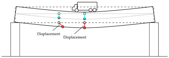
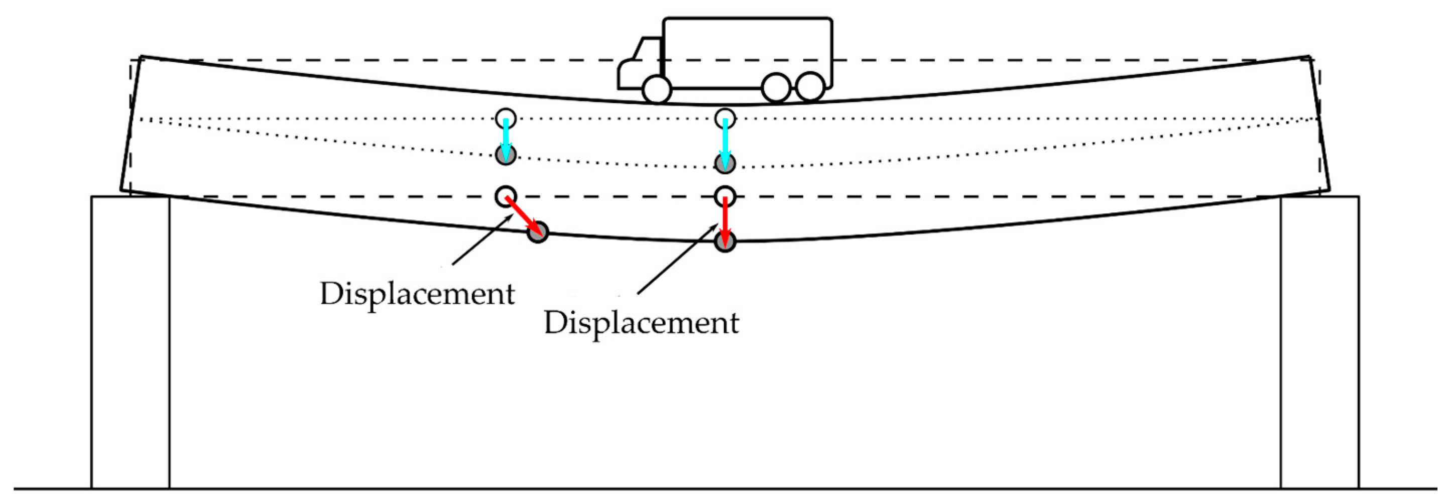
Since a radar can only detect the displacement component along the range direction, the effective movement is retrieved by supposing the displacement in the vertical direction. This assumption is often reasonable but is potentially incorrect when the detected scatter point is far from the so-called “neutral axis” of the bridge. Figure 1 pictorially shows how the effective displacement can have a vectorial direction that differs considerably from the vertical one. The detection of a single component can be misleading as experimentally shown by Dei et al. in 2013 [8].
Figure 1.
The blue arrows are the displacements of the points of the neutral axis (the dotted lines in the figure) of the bridge; the red arrows are the displacements of the points far from the neutral axis (the figure and the displacements are not to scale).
Recently, several authors proposed radar techniques for detecting two or three components. Monti-Guarnieri et al. [9] operated two radars simultaneously to detect the displacement vector of corner reflectors fixed to a pipe. The recent introduction of multiple input, multiple output (MIMO) for spaceborne radar [10], for ground-based radar [11,12,13], and in biomedical contexts [14] has prompted the creation of new solutions. Deng et al. [15] deployed three ground-based multiple input, multiple output (GB-MIMO) radar systems to measure 3D deformation of a movable corner reflector. All of these approaches have evident drawbacks in terms of complexity of the installation.
Pieraccini et al. [16,17,18] proposed a radar technique that uses a transponder in a bistatic configuration for detecting a further component of the displacement of a corner reflector. However, this approach can pose two issues: (1) the bistatic image can differ notably from the monostatic image (so it can be difficult to recognize the same physical targets in the two images), and (2) the bistatic angle is half of the angle between radar and transponder, which can lead to geometric configurations that are hardly deployable in the field.
In 2021, Miccinesi et al. [19] proposed a multi-monostatic radar for bridge monitoring using a MIMO radar: the two channels of the MIMO radar were located in different positions in the same side of the river. This method allows for simple measurement of two components of displacement, but the baseline (distance between the two MIMO channels) was not enough for long bridges.
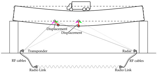
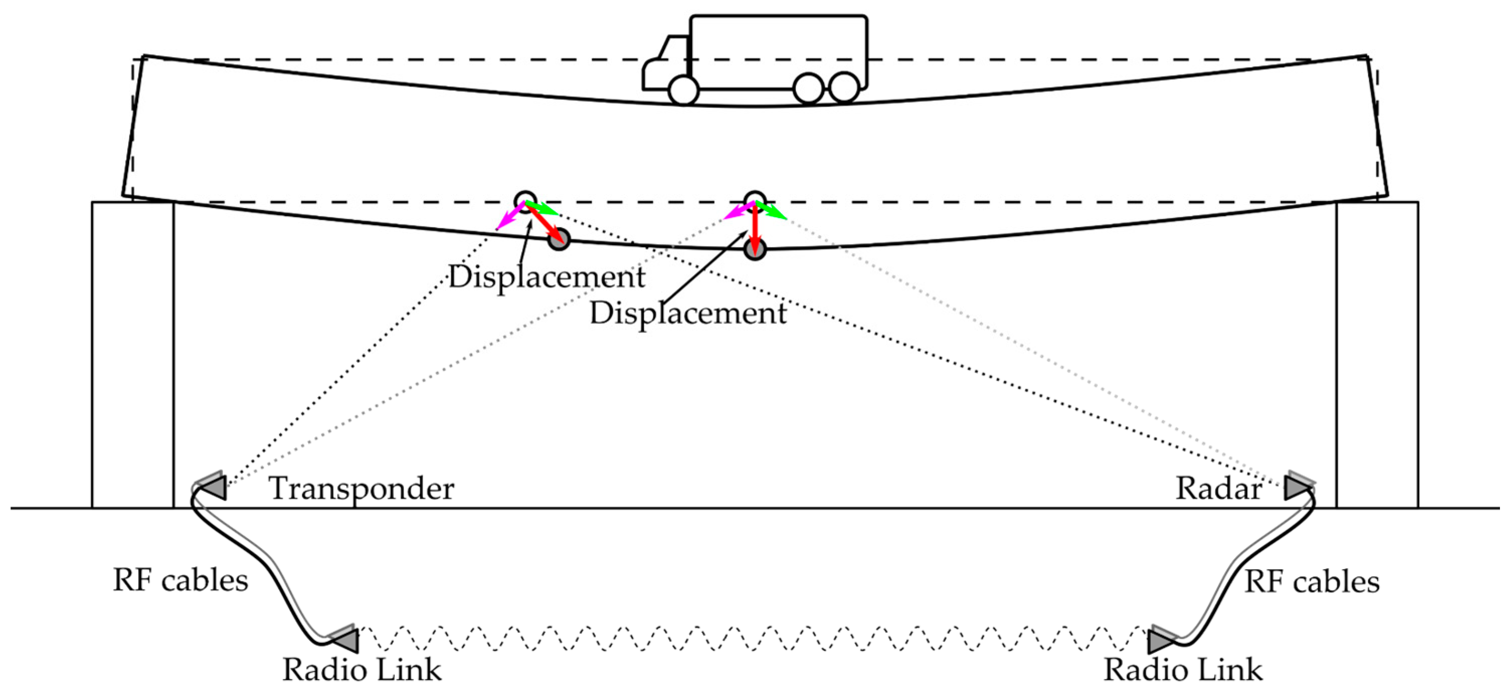
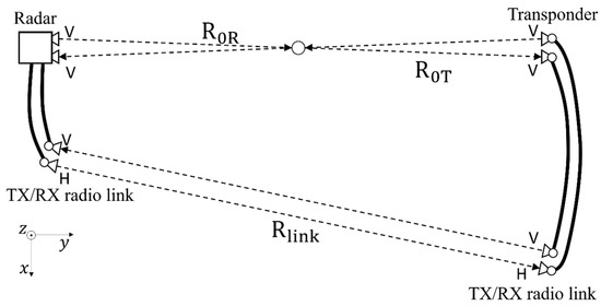
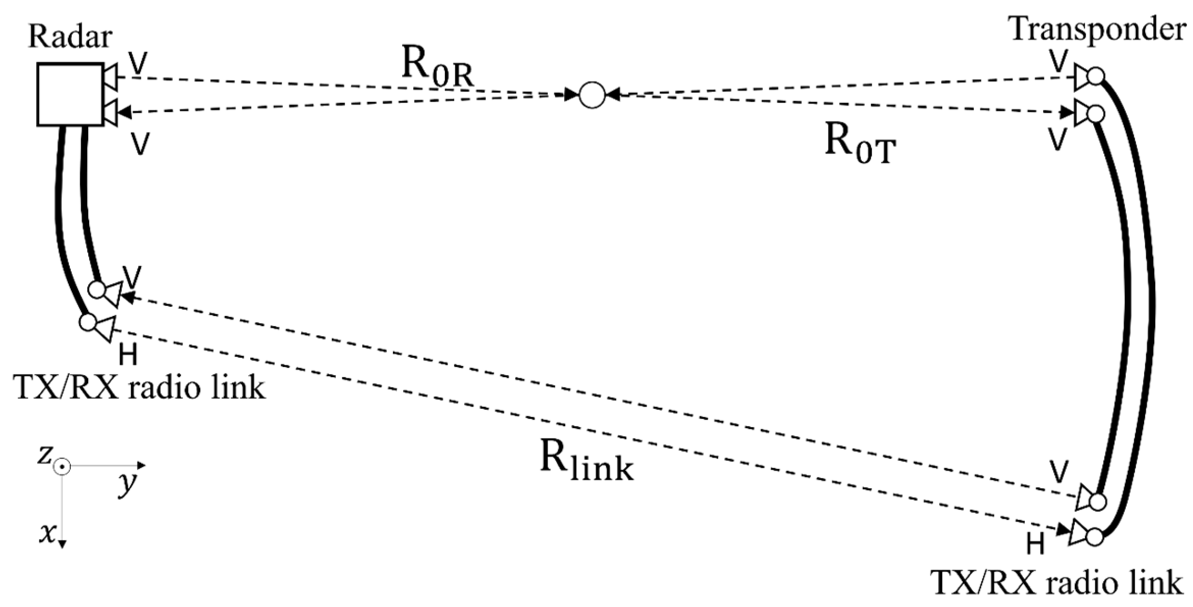
In this article, the authors propose an advanced technique based on [19]. The two channels are in the opposite banks of the river, and they are connected through a radio link as shown in Figure 2.
Figure 2.
Working principle of multi-monostatic interferometric radar with radio link (the figure and the displacements are not in scale).
2. Materials and Methods
2.1. Methods
The proposed technique is schematically shown in Figure 3. The radar is connected to an additional interferometric channel through a radio link.
Figure 3.
Scheme of a working principle of multi-monostatic interferometric radar with radio link (view form above).
The transponder is basically composed of a transmitting channel and a receiving channel. Each channel is composed of a horn antenna in vertical polarization and an amplifier system.
The radio link is composed of two transceiver units connected to the radar and the transponder. The transceiver unit is composed of two cross-polarized horn antennas and an amplifier system. The cross-polarization increases the isolation between the two channels to prevent possible self-oscillation.
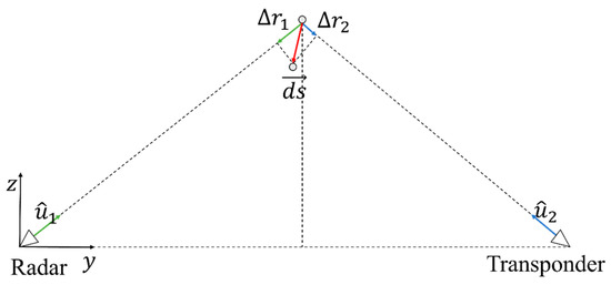
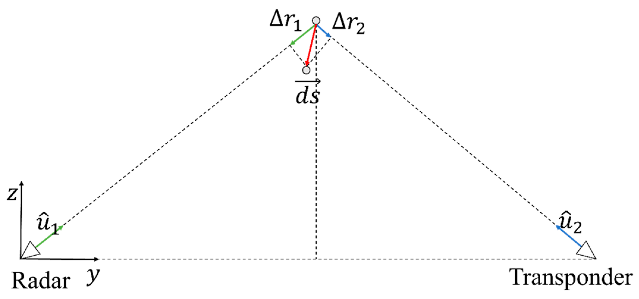
Figure 4 shows the geometry used for retrieving two components of displacement. The target is located between the two measurement points (radar and transponder). The two measurement points are able to detect two different components of displacement. It is possible to move from the radar/transponder coordinate system to the Euclidean coordinate system by using the following relationship:
where and are the displacement components along the y and z axes, and are the displacement measured by the radar and by the transponder. The displacement can be measured using the interferometric phase, :
Figure 4.
Measurement geometry for retrieving the yz components of displacement (side view).
In order to perform a preliminary assessment of the theoretical uncertainty, we can consider the following equation:
where and are the measurement uncertainty on and , and and are the uncertainty of the yz components. The abs operation of is performed element by element. Equation (3) can be calculated from Equation (1) and by using the linear properties of matrix calculus. Furthermore, we suppose the radar and the transponder operate with the same signal-to-noise ratio, i.e., . This is not always true, but it is a reasonable assumption for a preliminary assessment of uncertainty.
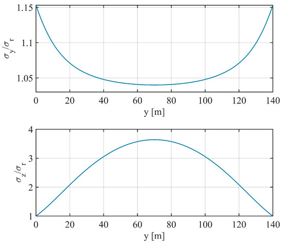
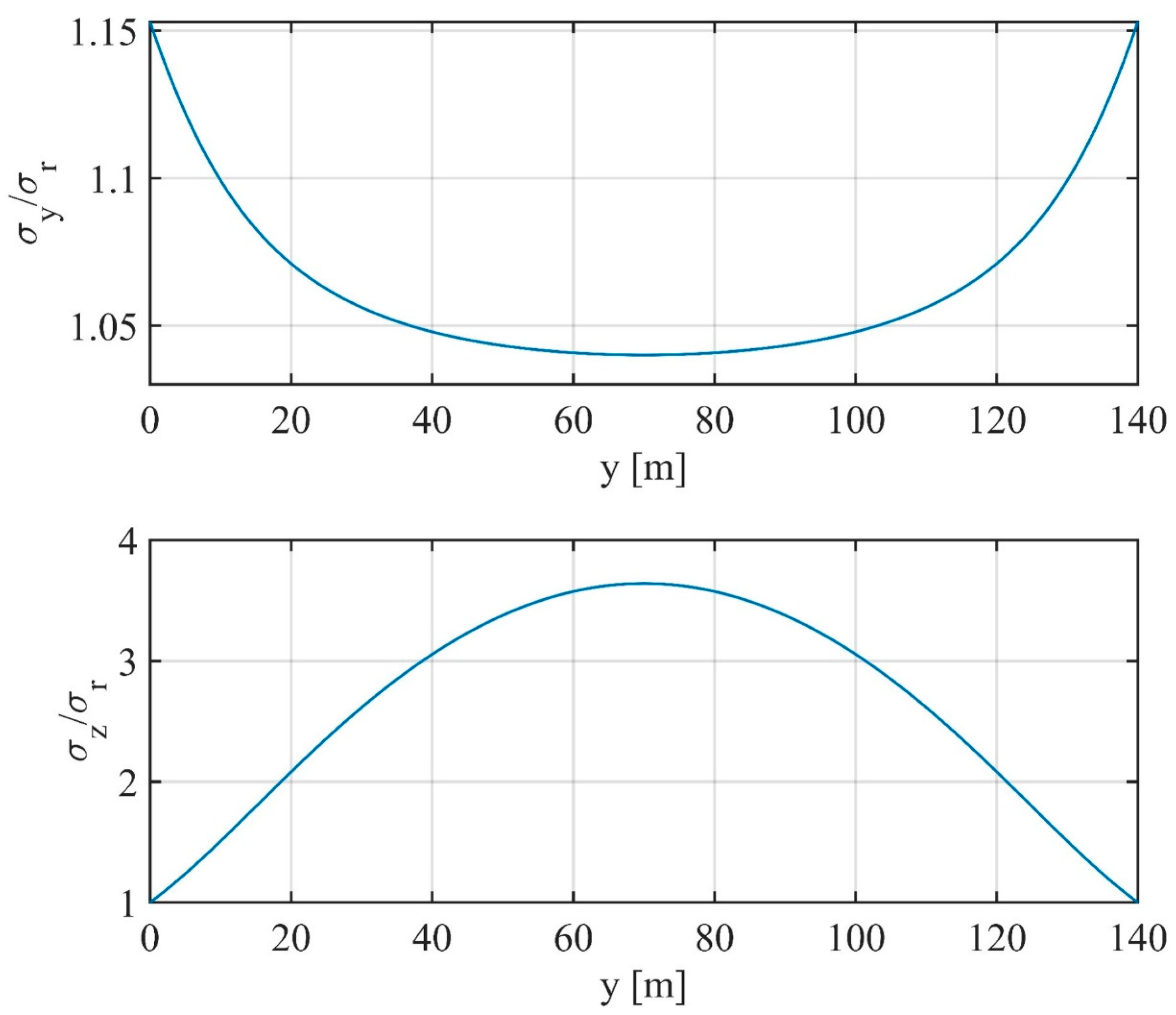
Figure 5 shows the calculated and the as functions of y. The radar is located in , the transponder in , and the target at , . The uncertainty along y () is maximum close to the radar and transponder and minimum in the middle of the bridge. Conversely, the uncertainty along z () is maximum in the middle of the bridge and minimum close to the pillars.
Figure 5.
Theoretical uncertainty calculated using Equation (3).
2.2. Power Budget of Radio Link
The power budget of radio link is a key point of this method. Indeed, the signal-to-noise ratio of the transponder has to be almost the same as that of the radar. Generally, the power budget can be estimated combining radar equation, free-space geometrical attenuation, and RF cables losses.
In reference to Figure 3, the power budget (PB) can be estimated as follows:
where and are the received power of the transponder and radar, respectively; is the transmitting power; is the cumulative RF cable attenuation; is the antenna gain (supposed almost equal for all antennas); is the wavelength; and and are the radar cross-sections. If the distance is equal to the distance and the radar cross-sections are supposed similar, the PB strongly depends on the radio link distance ().
The amplifiers of the transceivers and transponder must compensate the PB to obtain almost the same value of received power in the two channels.
2.3. Equipment
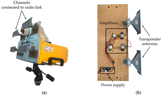
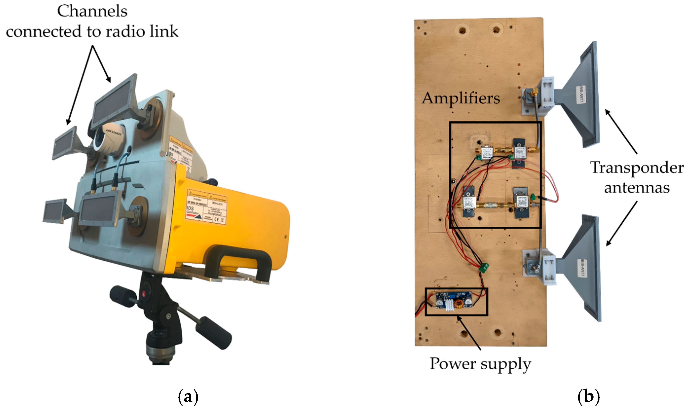
The radar used is a modified version of IBIS-FM MIMO [12], developed by IDS Georadar, Pisa, Italy. Figure 6a shows the IBIS-FM MIMO with four antennas connected. This radar provides a continuous wave frequency modulated signal with central frequency of and maximum bandwidth of . The transmitting power is about . The radar has two TX channels and two RX channels that are acquired sequentially. The acquisition frequency depends on the radar parameters (unambiguous range, range resolution, etc.).
Figure 6.
Pictures of the equipment used for testing of the multi-monostatic interferometric radar with radio link: (a) the IBIS-FM MIMO radar [12], (b) an example of transponder.
The antennas used are standard horn antennas with the same gain of about 15 dB.
An example transponder is shown in Figure 6b. The amplifiers are ZX60-183-A, produced by Mini Circuits, New York, USA. The gain of these amplifiers is about 30 dB.
3. Results
The multi-monostatic interferometric radar with radio link was tested in controlled scenarios and in the case study of Indiano Bridge, Florence, Italy.
In controlled scenarios, we tested the system to verify the multi-monostatic method summarized in Equation (1) and to verify the power budget in Equation (4). Equations (1) and (4) were tested separately.
3.1. Test of Multi-Monostatic Interferometric Radar (without Radio Link)
Figure 7 shows the setup and the block scheme used to verify the working principle (i.e., Equation (1)). The target was a metallic bar connected to the roof of the building at 2.61 m height in respect to the radar. The bar could oscillate freely along the vertical axis. Two identical corner reflectors were fixed at the bar extremity. The radar was in , the target was in , and the transponder was in .
Figure 7.
Experimental setup for verification of Equation (1): (a) picture of experimental setup, (b) block scheme used.
The power budget of the system can be calculated according to Figure 7b. In this case, we used two amplifiers with gain of 30 dB. The signal of the transponder was almost equal to the signal of the radar ().
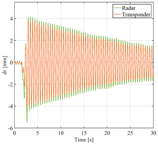
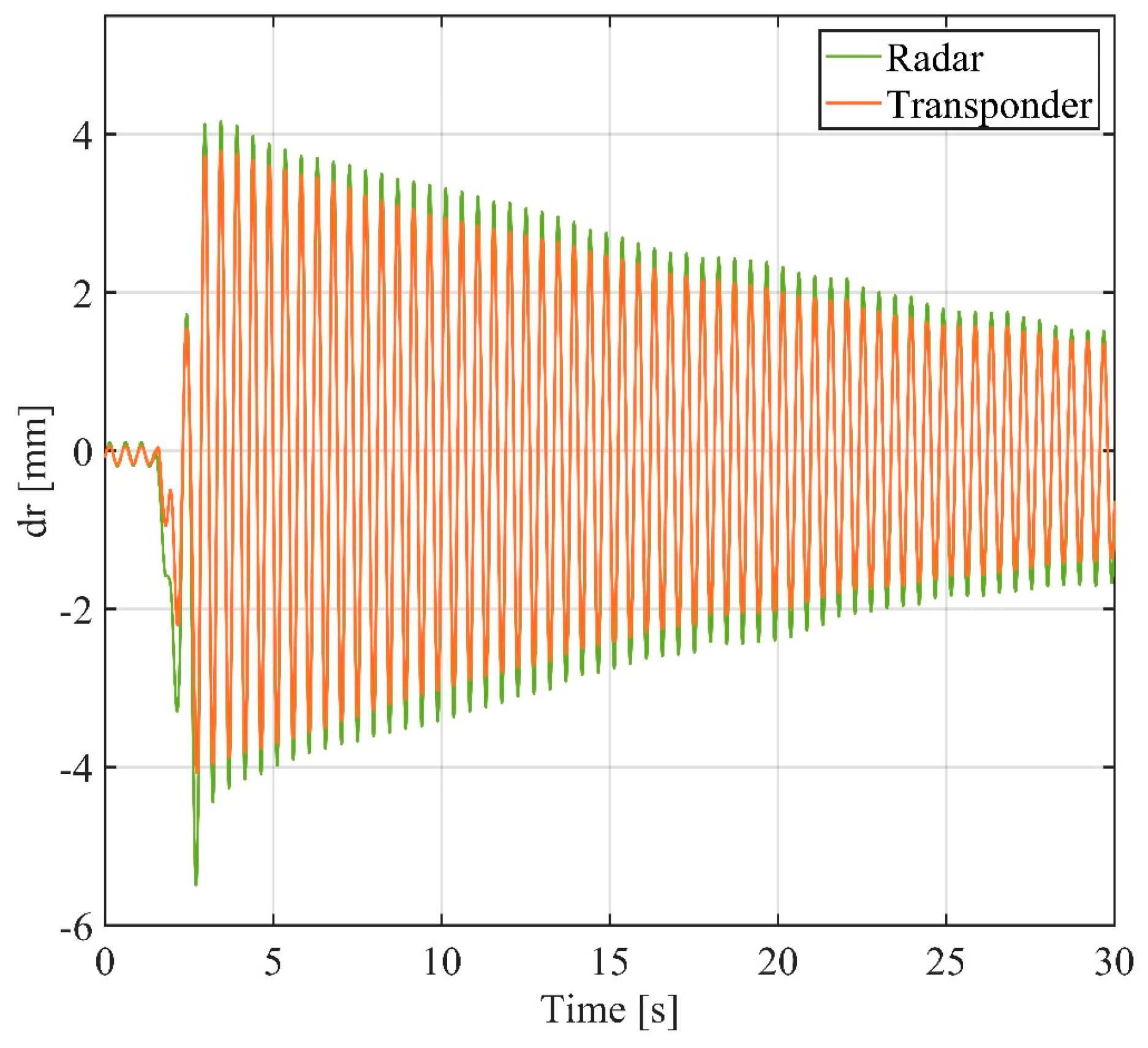
The radar image is shown in Figure 8. The targets were in the expected positions both for the radar and transponder. The signal of transponder is higher than that of the radar. This discrepancy is not critical and could be due to misalignment of the radar or differences in target reflectivity. The interferometry was performed using the interferometric phase of the peaks. Figure 9 shows the displacements measured by the radar and the transponder.
Figure 8.
Radar image of the two corner reflectors fixed on the metallic bar.
Figure 9.
Displacement measured by the radar and the transponder.
The two signals in Figure 9 are in phase, and they appear very similar. Using Equation (1), it is possible to convert the displacements along radar and transponder directions into the displacement vector.
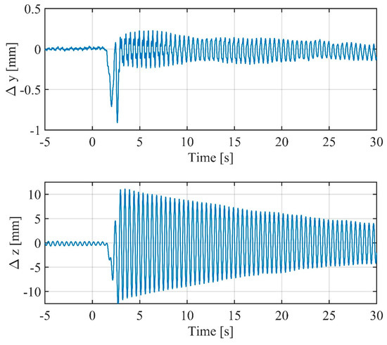
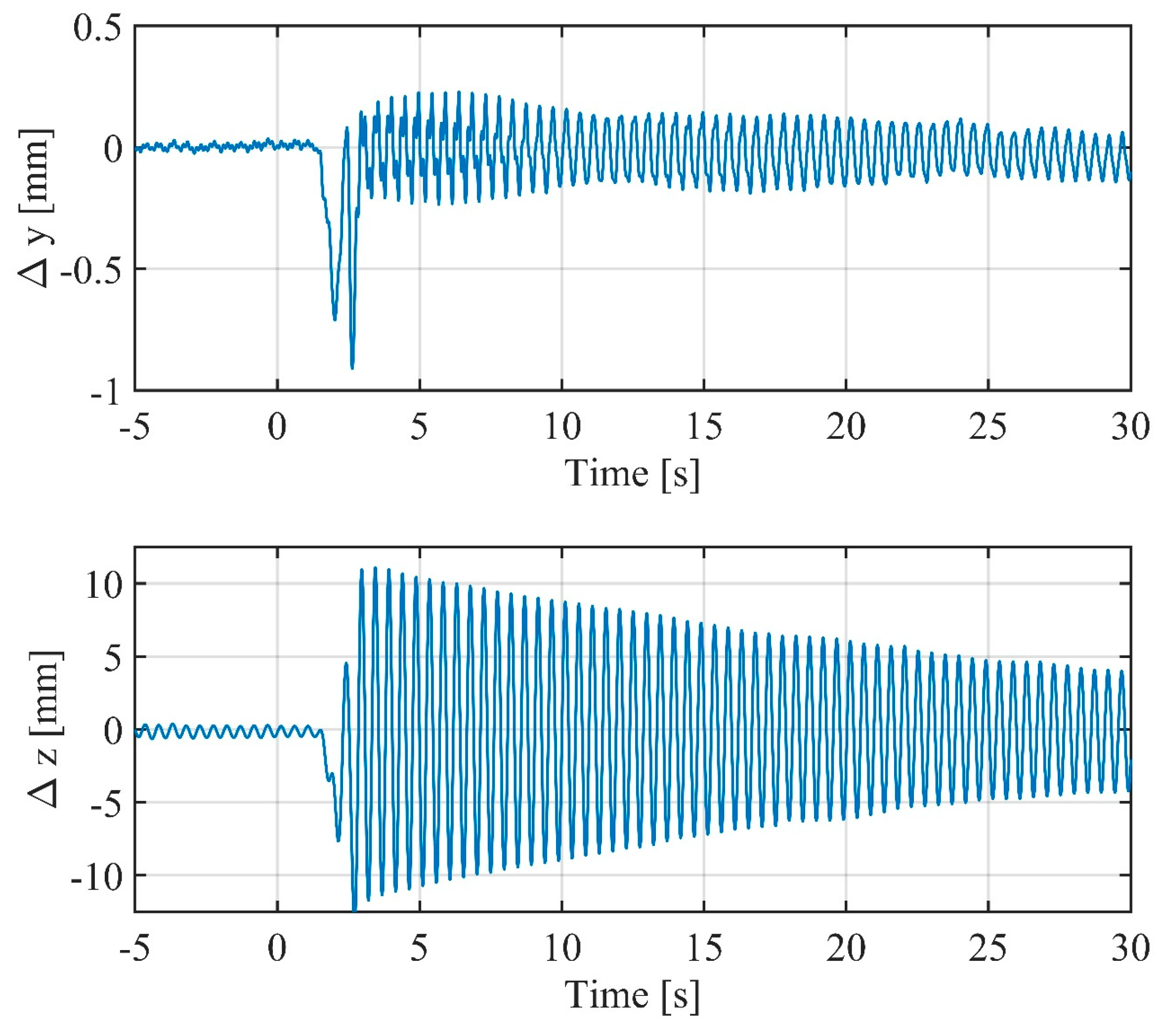
Figure 10 shows the two components retrieved using Equation (1). The main displacement is along the z axis. There is a residual displacement along the y axis with maximum elongation of about 0.5 mm and standard deviation of 0.11 mm. This displacement along y is considerably lower than the displacement along z (20 mm).
Figure 10.
Displacement components retrieved using Equation (1).
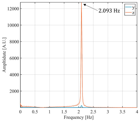
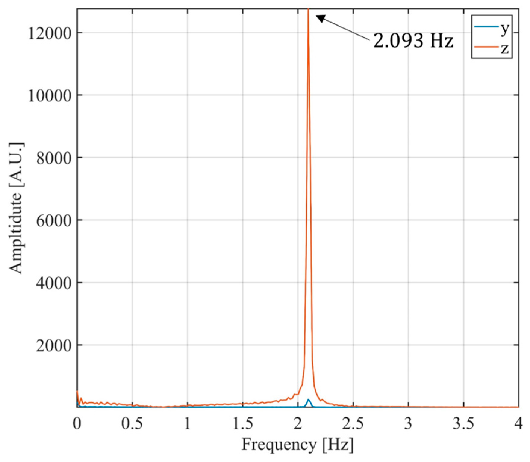
Figure 11 shows the natural frequency retrieved by calculating the Fourier transform of the zy components. The natural frequency of the target along z is 2.093 Hz. The residual displacement along y has the same frequency (meaning that the y-displacement is not given by a different vibration mode); therefore, this signal can be considered as a residual artefact of the geometrical projection.
Figure 11.
Natural frequency of target in Figure 7.
3.2. Test of Multi-Monostatic Interferometric Radar with Radio Link
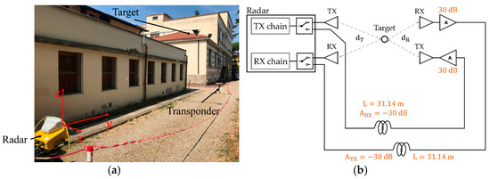
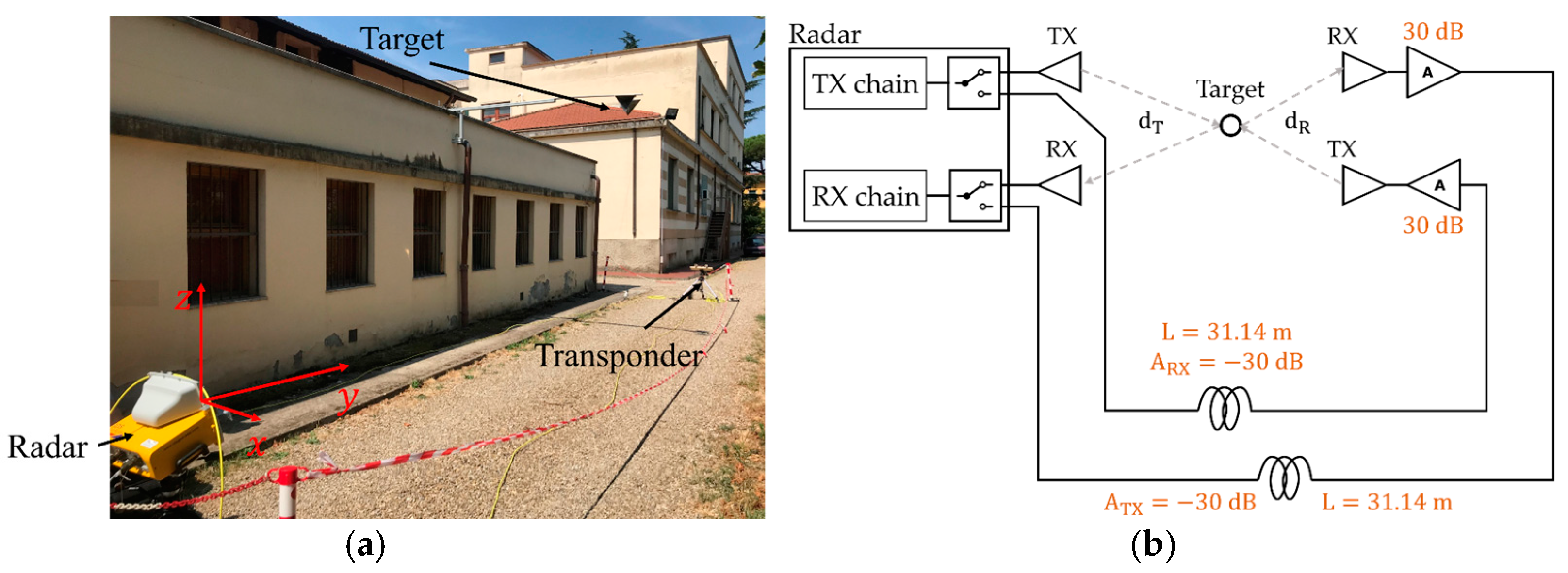
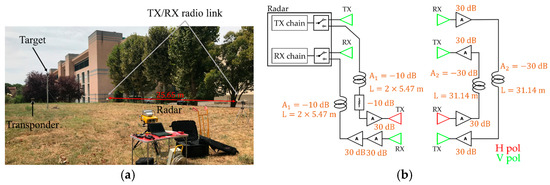
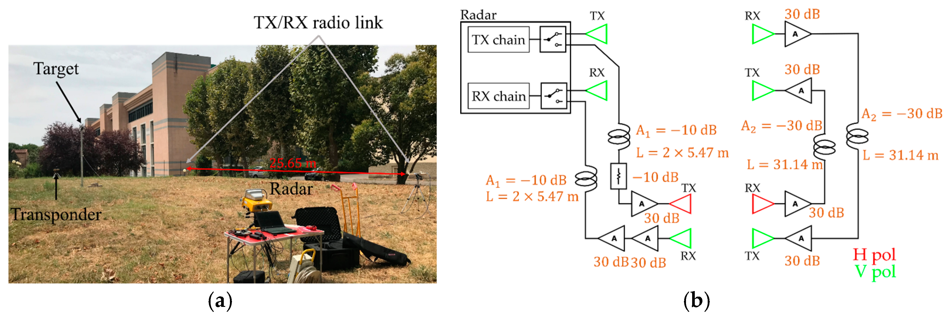
The power level of the radio link was tested in a scaled scenario as shown in Figure 12a. A target was located between the radar and transponder. The radio link was located on the right in respect to the radar, and it was long.
Figure 12.
Experimental setup for verification of Equation (4): (a) picture of experimental setup, (b) block scheme used.
The power budget evaluated using Equation (4), with reference to Figure 12b, was about without amplifiers. We used seven amplifiers of 30 dB gain to compensate the PB. The resulting power budget was about .
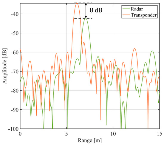
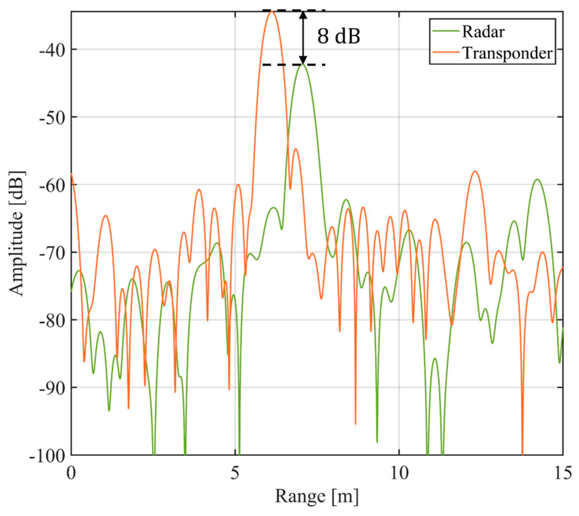
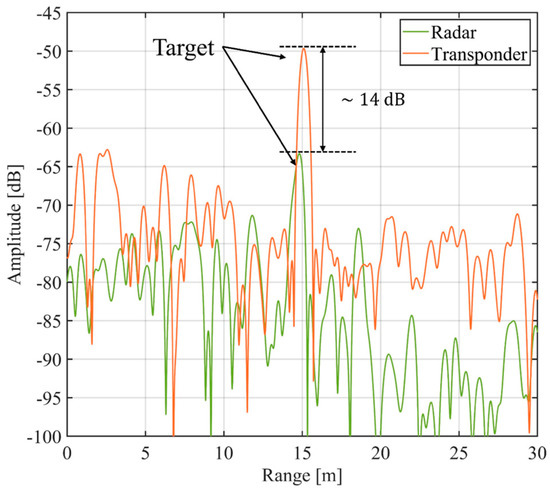
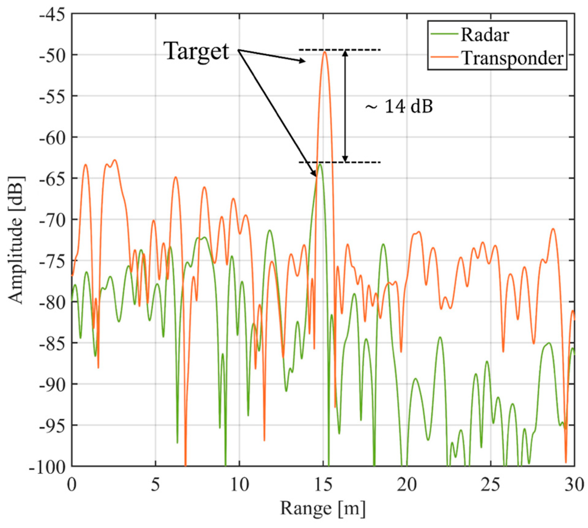
Figure 13 shows the image obtained using the radar and transponder. The signal of the transponder was about 14 dB larger than the signal of the radar. This value almost corresponds to the PB estimated using Equation (4) and the scheme of Figure 12b.
Figure 13.
Amplitude image registered by radar and by transponder using the radio link.
3.3. Case Study—Indiano Bridge, Florence, Italy
The multi-monostatic interferometric radar with radio link was tested at Indiano Bridge, Florence, Italy. This bridge is an earth-anchored, cable-stayed bridge, and it was built between 1972 and 1978.
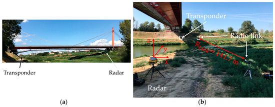
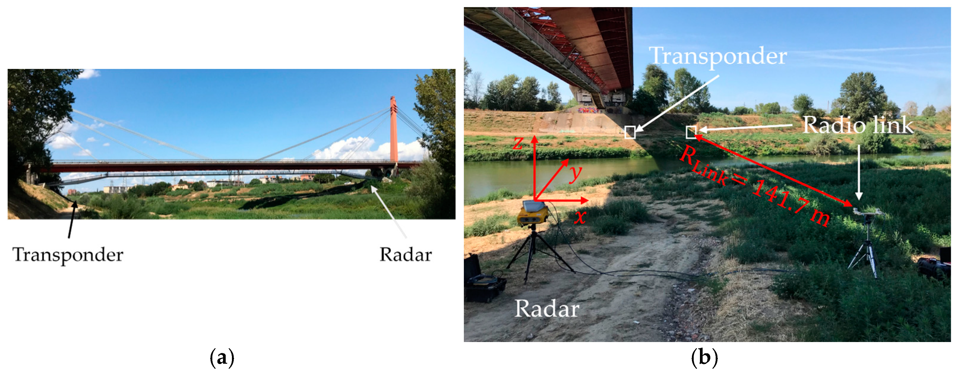
The radar was installed on the right bank of the bridge as shown in Figure 14. The radio link was 141.7 m long. The distance of radio link was evaluated using a corner reflector located with the radio link transceiver on the bank of the transponder. The block scheme used was almost the same as in Figure 12b with two more amplifiers on the receiving channel.
Figure 14.
Experimental setup of Indiano Bridge test: (a) picture of Indiano Bridge, (b) experimental setup.
During the test, the bridge was subjected only to vehicular traffic.
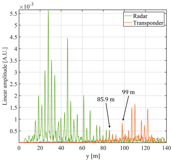
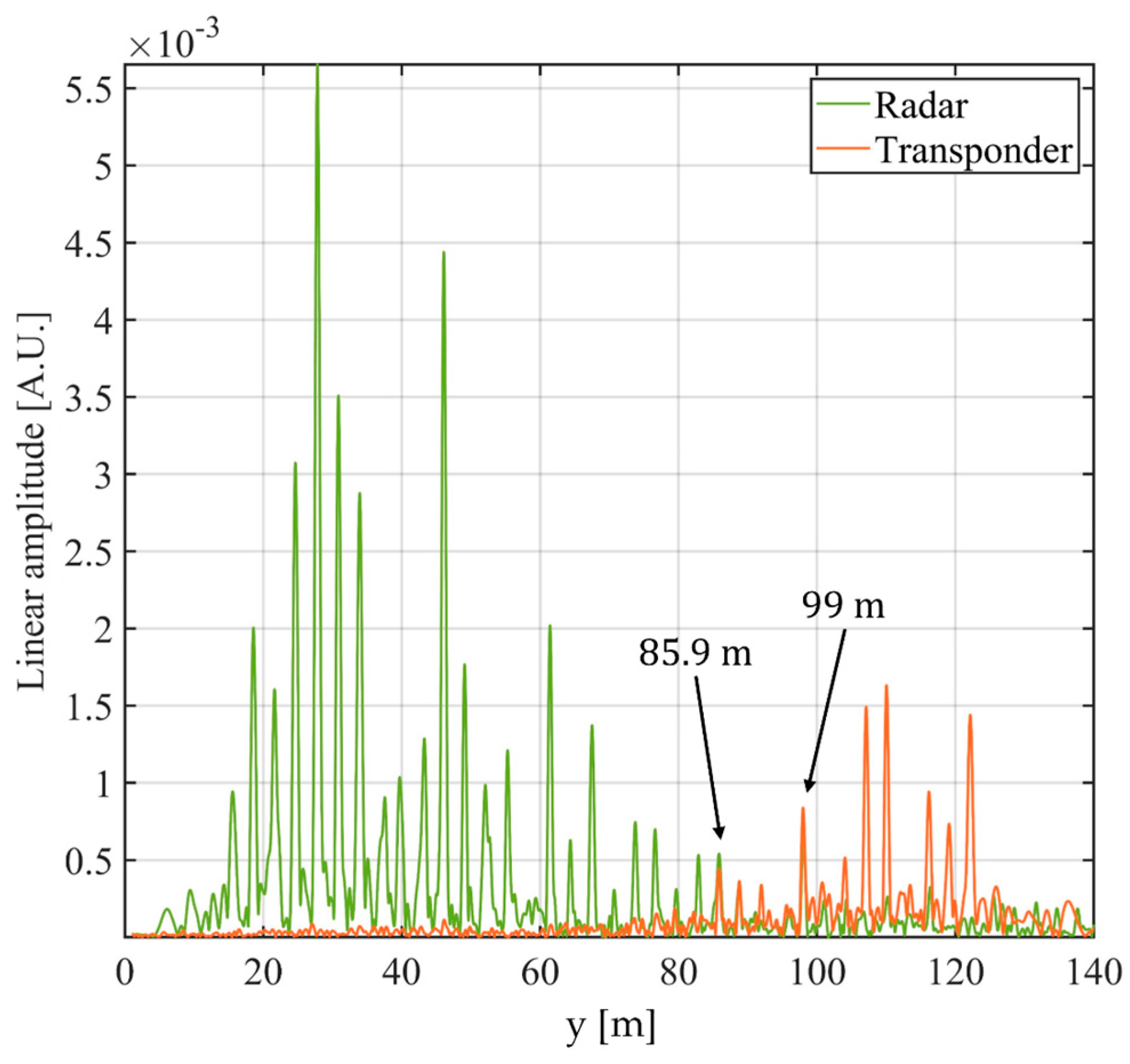
The radar was located in , and the transponder was in . The bridge was 14.40 m high in respect to the radar. In order to identify the target position along the y axis, the radar and the transponder images were focused along the bridge span as described in [17]. Figure 15 shows the focused image. For the sake of conciseness, we report only the displacements of the targets at and at , but the method can be applied to all peaks between 70 m to 120 m.
Figure 15.
Radar and transponder images focused on bridge span.
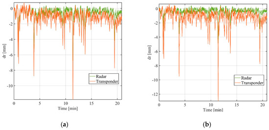
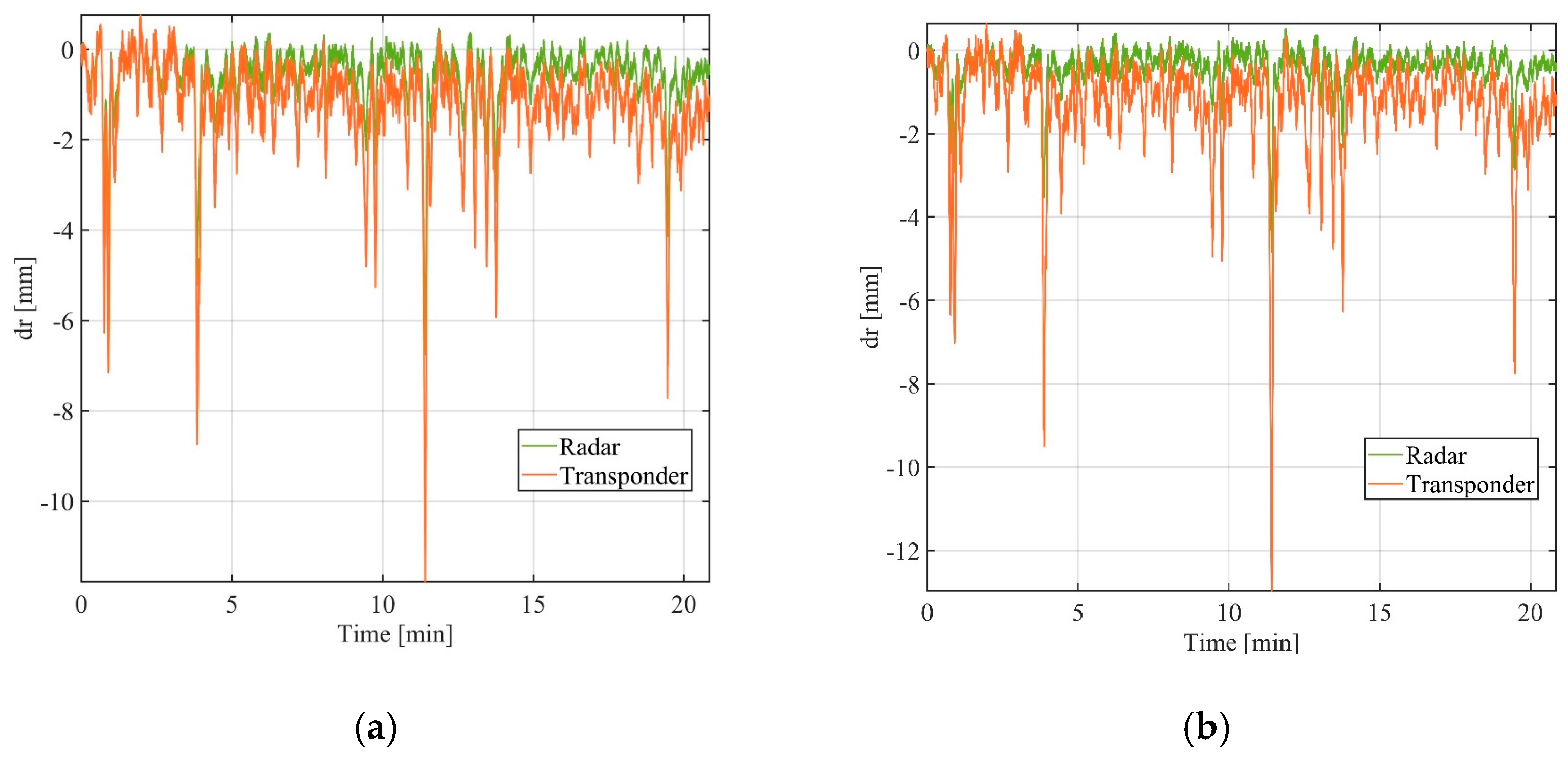
The displacements measured by the radar and the transponder for the two targets are reported in Figure 16.
Figure 16.
Displacement measured by the radar and the transponder for target at y = 85.9 m (a) and at y = 99 m (b).
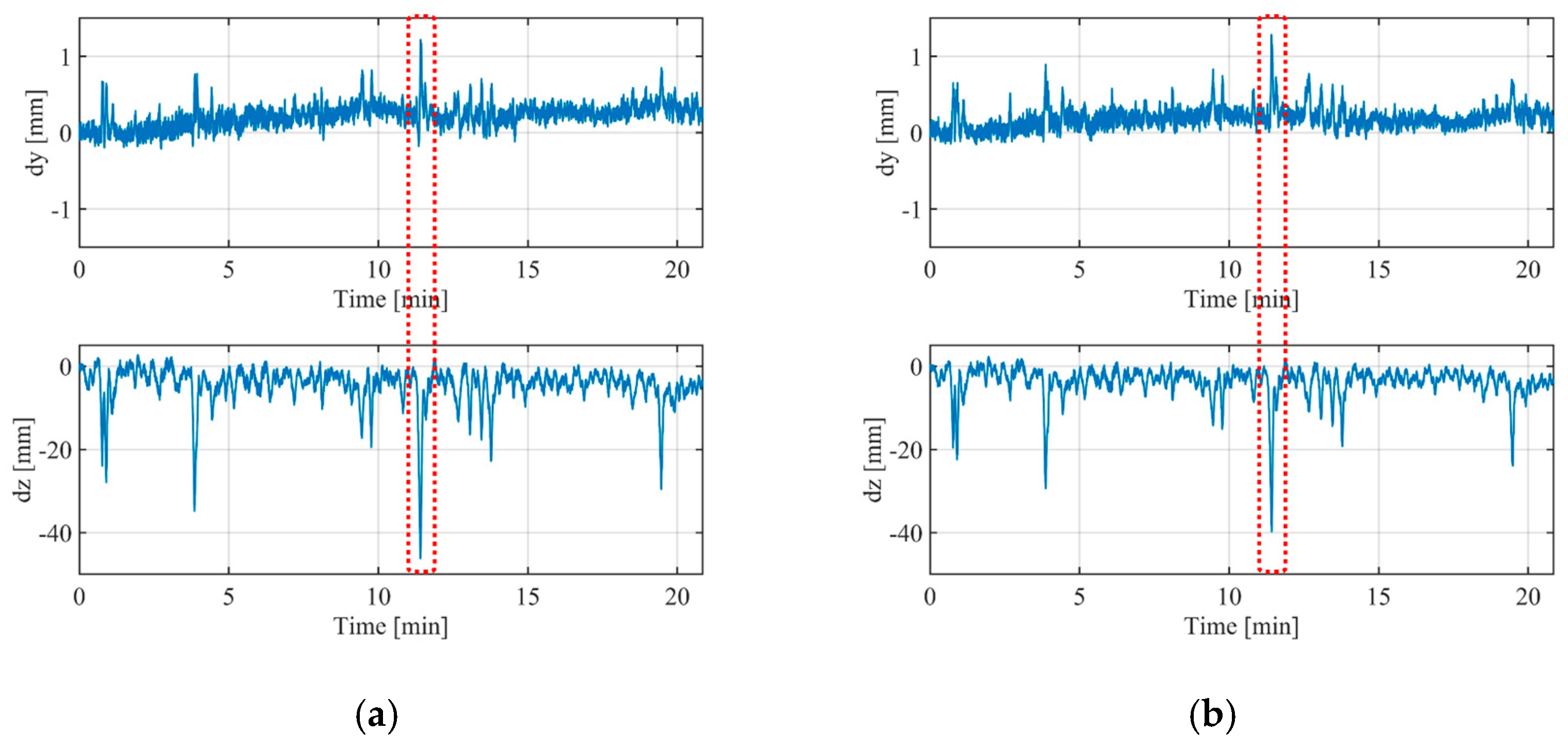
The displacement components retrieved using Equation (1) are shown in Figure 17. Most of the displacement is along z, even if it is possible to detect y components during the impulsive stimulus (for example, at ).
Figure 17.
Displacement components of target at y = 85.9 m (a) and at y = 99 m (b).
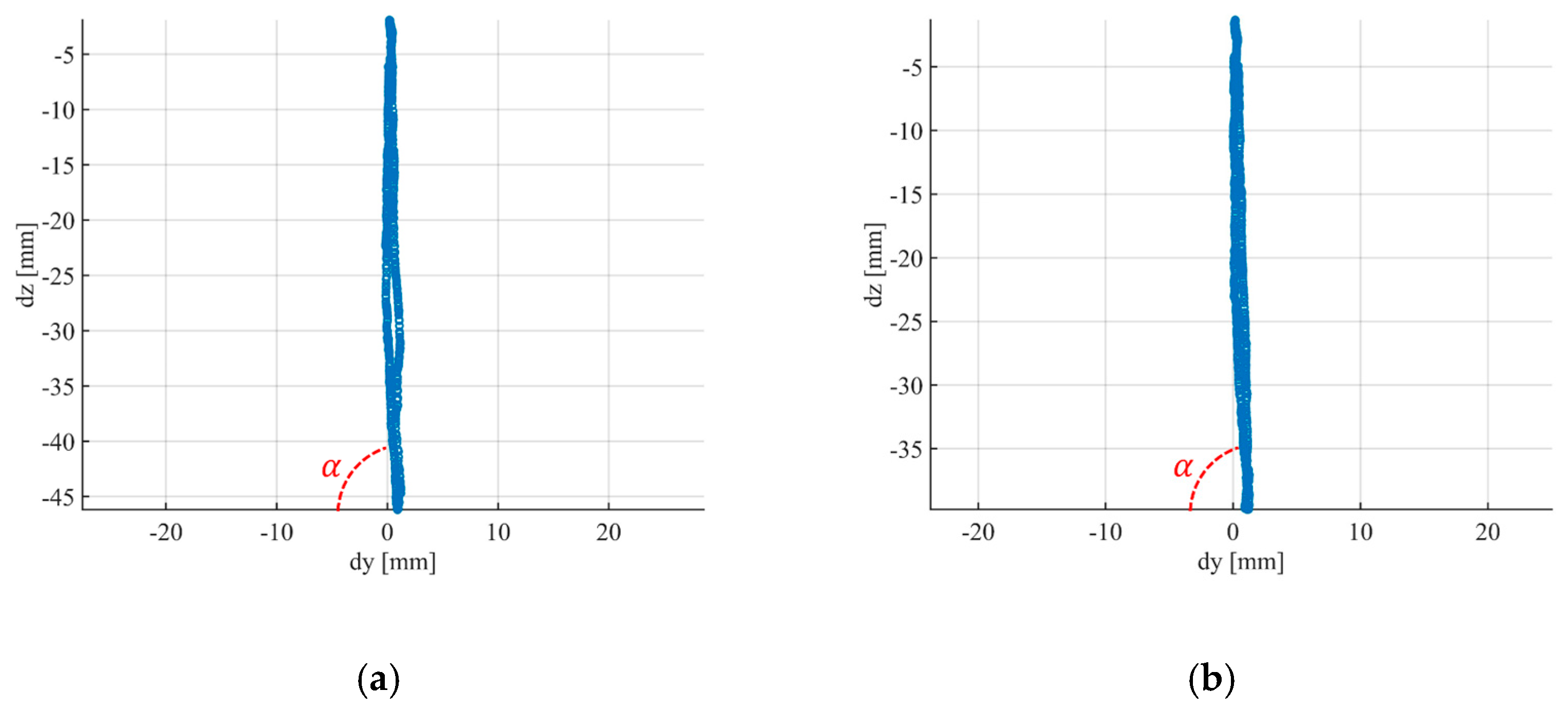
As a further application of this technique, we retrieved the direction of the displacement vector. Figure 18a,b show the retrieved direction of the two targets for the spotlighted stimulus (Figure 17). The displacement direction of the target at y = 85.9 m was inclined by an angle with respect to the y axis. The displacement direction of the target at y = 99 m was at .
Figure 18.
Displacement axis of the target at y = 85.9 m (a) and of the target at y = 99 m (b).
4. Conclusions
In this paper, a multi-monostatic radar with radio link was presented. The authors verified in a controlled environment both the methodology described in Section 2.1 and the power budget of the radio link described in Section 2.2.
The method was verified using a horizontal oscillating bar without the radio link. The system was able to detect vertical and horizonal displacements. The main component was along the vertical axis, although there was a small horizontal residual component (probably a geometrical projection artifact).
The power budget of the radio link was evaluated using Equation (4) for each case, and the power loss was compensated with a suitable number of amplifiers.
The multi-monostatic interferometric radar was tested in a case study with a radio link of about 140 m long. The case study was the Indiano Bridge in Florence, Italy. The equipment was able to detect the displacement of several targets. The number of targets detected by the radar and by the transponder was not equal (the radar detected more targets than the transponder). This fact is probably due to a misalignment of the radio link, which caused power losses that were larger than we expected. In a practical implementation of this technique, this problem could be solved using a power detector for optimization of the alignment of the radio link.
Another point worth discussing for a practical implementation of this technique is the maximum length of the bridge. The radar was designed to operate up to 5 km, but in this specific application, we must consider the ratio between length and height of the bridge. As rule of thumb, the length has to be no larger than 20/30 times the height in order to have a reasonable component of the displacement along the view direction.
Author Contributions
Conceptualization, M.P. and L.M.; methodology, L.M.; software, L.M.; validation, L.M.; formal analysis, L.M.; investigation, L.M., O.A., A.B. and T.C.; resources, M.P.; data curation, L.M.; writing—original draft preparation, L.M.; writing—review and editing, A.B.; visualization, L.M.; supervision, M.P.; project administration, M.P.; funding acquisition, M.P. All authors have read and agreed to the published version of the manuscript.
Funding
This research received no external funding.
Data Availability Statement
Data are available upon request.
Conflicts of Interest
The authors declare no conflict of interest.
References
- Pieraccini, M.; Parrini, F.; Fratini, M.; Atzeni, C.; Spinelli, P.; Micheloni, M. Static and dynamic testing of bridges through microwave interferometry. NDT E Int. 2007, 40, 208–214. [Google Scholar] [CrossRef] [Scilit]
- Stabile, T.A.; Perrone, A.; Gallipoli, M.R.; Ditommaso, R.; Ponzo, F.C. Dynamic survey of the Musmeci bridge by joint application of ground-based microwave radar interferometry and ambient noise standard spectral ratio techniques. IEEE Geosci. Remote. Sens. Lett. 2013, 10, 870–874. [Google Scholar] [CrossRef] [Scilit]
- Placidi, S.; Meta, A.; Testa, L.; Rödelsperger, S. Monitoring structures with FastGBSAR. In Proceedings of the 2015 IEEE Radar Conference, Johannesburg, South Africa, 27–30 October 2015; pp. 435–439. [Google Scholar]
- Luzi, G.; Crosetto, M.; Fernandez, E. Radar interferometry for monitoring the vibration characteristics of buildings and civil structures: Recent case studies in Spain. Sensors 2017, 17, 669. [Google Scholar] [CrossRef] [Scilit] [PubMed]
- Zhang, B.; Ding, X.; Werner, C.; Tan, K.; Zhang, B.; Jiang, M.; Zhao, J.; Xu, Y. Dynamic displacement monitoring of long-span bridges with a microwave radar interferometer. ISPRS J. Photogramm. Remote Sens. 2018, 138, 252–264. [Google Scholar] [CrossRef] [Scilit]
- Cardillo, E.; Caddemi, A. Radar Range-Breathing Separation for the Automatic Detection of Humans in Cluttered Environments. IEEE Sens. J. 2021, 21, 14043–14050. [Google Scholar] [CrossRef] [Scilit]
- Rodriguez, D.; Li, C. Sensitivity and Distortion Analysis of a 125-GHz Interferometry Radar for Submicrometer Motion Sensing Applications. IEEE Trans. Microw. Theory Tech. 2019, 67, 5384–5395. [Google Scholar] [CrossRef] [Scilit]
- Dei, D.; Mecatti, D.; Pieraccini, M. Static Testing of a Bridge Using an Interferometric Radar: The Case Study of “Ponte degli Alpini,” Belluno, Italy. Sci. World J. 2013, 2013, 504958. [Google Scholar] [CrossRef] [Scilit] [PubMed]
- Guarnieri, A.M.; Falcone, P.; D’Aria, D.; Giunta, G. 3D Vibration Estimation from Ground-Based Radar. Remote Sens. 2018, 10, 1670. [Google Scholar] [CrossRef] [Scilit]
- Wang, J.; Chen, L.; Liang, X.; Ding, C.-B.; Li, K. Implementation of the OFDM Chirp Waveform on MIMO SAR Systems. IEEE Trans. Geosci. Remote Sens. 2015, 53, 5218–5228. [Google Scholar] [CrossRef] [Scilit]
- Tarchi, D.; Oliveri, F.; Sammartino, P.F. MIMO Radar and Ground-Based SAR Imaging Systems: Equivalent Approaches for Remote Sensing. IEEE Trans. Geosci. Remote Sens. 2013, 51, 425–435. [Google Scholar] [CrossRef] [Scilit]
- Michelini, A.; Coppi, F.; Bicci, A.; Alli, G. SPARX, a MIMO Array for Ground-Based Radar Interferometry. Sensors 2019, 19, 252. [Google Scholar] [CrossRef] [Scilit] [PubMed]
- Hu, C.; Wang, J.; Tian, W.; Zeng, T.; Wang, R. Design and Imaging of Ground-Based Multiple-Input Multiple-Output Synthetic Aperture Radar (MIMO SAR) with Non-Collinear Arrays. Sensors 2017, 17, 598. [Google Scholar] [CrossRef] [Scilit] [PubMed]
- Cardillo, E.; Caddemi, A. A Review on Biomedical MIMO Radars for Vital Sign Detection and Human Localization. Electronics 2020, 9, 1497. [Google Scholar] [CrossRef] [Scilit]
- Deng, Y.; Hu, C.; Tian, W.; Zhao, Z. 3-D Deformation Measurement Based on Three GB-MIMO Radar Systems: Experimental Verification and Accuracy Analysis. IEEE Geosci. Remote Sens. Lett. 2020, 1–5. [Google Scholar] [CrossRef] [Scilit]
- Pieraccini, M.; Miccinesi, L.; Rojhani, N. A GBSAR Operating in Monostatic and Bistatic Modalities for Retrieving the Displacement Vector. IEEE Geosci. Remote Sens. Lett. 2017, 14, 1–5. [Google Scholar] [CrossRef] [Scilit]
- Miccinesi, L.; Pieraccini, M. Monostatic/Bistatic Interferometric Radar for Monitoring Slander Structures. In Proceedings of the 2019 IEEE Conference on Antenna Measurements & Applications (CAMA), Kuta, Bali, Indonesia, 23–25 October 2019. [Google Scholar]
- Miccinesi, L.; Pieraccini, M. Bridge Monitoring by a Monostatic/Bistatic Interferometric Radar Able to Retrieve the Dynamic 3D Displacement Vector. IEEE Access 2020, 8, 210339–210346. [Google Scholar] [CrossRef] [Scilit]
- Miccinesi, L.; Beni, A.; Pieraccini, M. Multi-Monostatic Interferometric Radar for Bridge Monitoring. Electronics 2021, 10, 247. [Google Scholar] [CrossRef] [Scilit]
Publisher’s Note: MDPI stays neutral with regard to jurisdictional claims in published maps and institutional affiliations. |
© 2021 by the authors. Licensee MDPI, Basel, Switzerland. This article is an open access article distributed under the terms and conditions of the Creative Commons Attribution (CC BY) license (https://creativecommons.org/licenses/by/4.0/).